presentación de powerpoint - psim...
TRANSCRIPT

The easier and faster way
to design the control of
your power converter
smartctrl®
Juan Pablo RodriguezSmartCtrl Development Manager

Table of contents
SmartCtrl: Control Design for Power Electronics 2
- Introduction: What SmartCtrl is
- Features
- Capabilities
- Application Examples: PSIM & SmartCtrl
• PFC Boost Converter
• Resonant Converter
• Single Phase Inverter

SmartCtrl: Control Design for Power Electronics 3
What SmartCtrl is
SmartCtrl: Control Design for Power Electronics 4
What SmartCtrl is
After over 20 years of experience in the field of power electronics systems SmartCtrl software is beingdeveloped as a platform in which, a part of our knowledge related to control in power electronic systems, iscollected.
SmartCtrl
SmartCtrl is a general-purpose controller design software specifically for power electronics application. Itfeatures:
- a friendly interface- simple workflow- easy to understand display of control loop stability and performance.
Using SmartCtrl, one can design controllers of various power converters easily and very quickly.
SmartCtrl Pro
SmartCtrl Pro adds the digital controller design option to SmartCtrl:
- One can design a controller in the analog s-domain, define digital delay, and check the control loopstability
- SmartCtrl Pro allows to calculate the z-domain coefficients of digital compensators to be implementedon digital devices
It is a good practice to compare the discretized compensator with the original analog one.

SmartCtrl: Control Design for Power Electronics 5
Features
SmartCtrl: Control Design for Power Electronics 6
From the specs to the Design
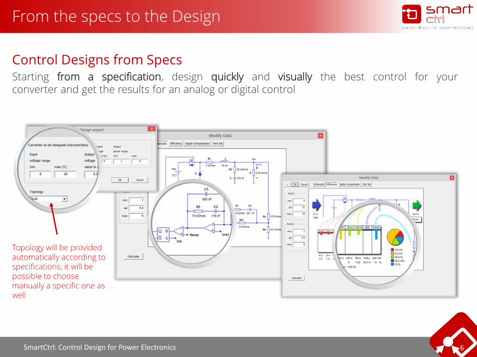
Control Designs from SpecsStarting from a specification, design quickly and visually the best control for yourconverter and get the results for an analog or digital control
Topology will be provided automatically according to specifications; it will be possible to choose manually a specific one as well
SmartCtrl: Control Design for Power Electronics 7
Real Time Updated
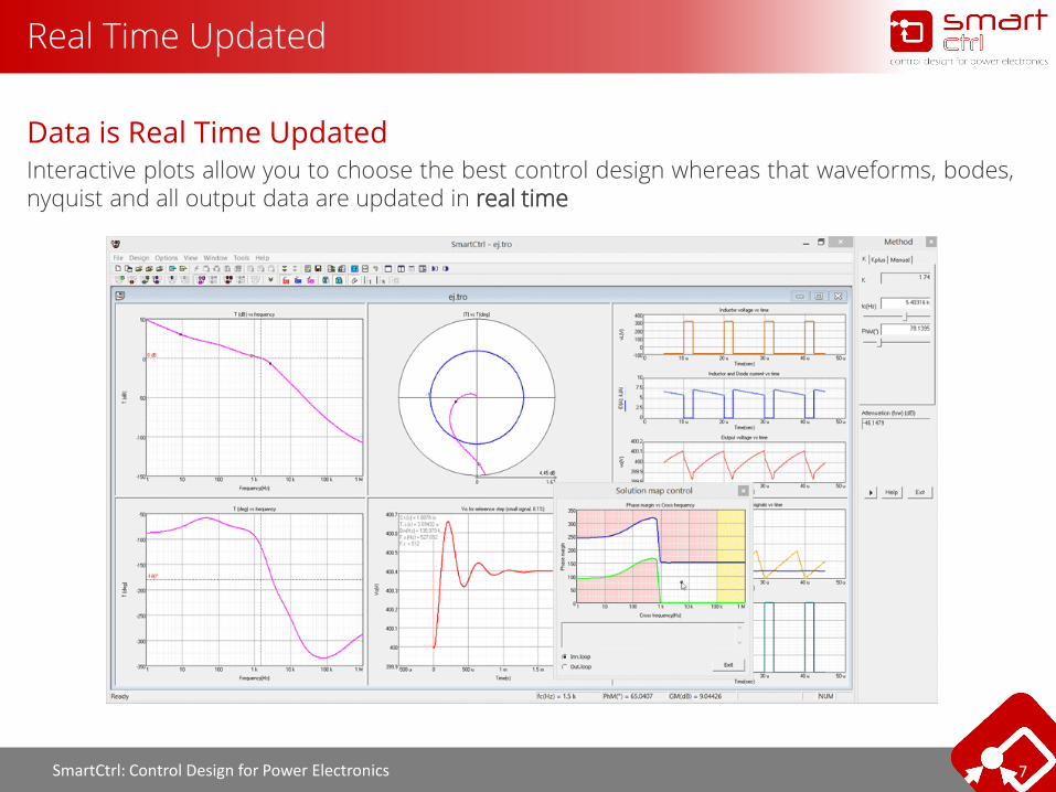
Data is Real Time UpdatedInteractive plots allow you to choose the best control design whereas that waveforms, bodes,nyquist and all output data are updated in real time

SmartCtrl: Control Design for Power Electronics 8
Multi-loop Control Structures
Multiloop Control StructuresAverage-Current Mode Control and Peak-Current Mode Control are supported in SmartCtrl:
Average – current control
- Inner and outer compensator design
Peak – current mode control
- Compensating ramp design- High frequency effects
SmartCtrl: Control Design for Power Electronics 9
Solutions Map
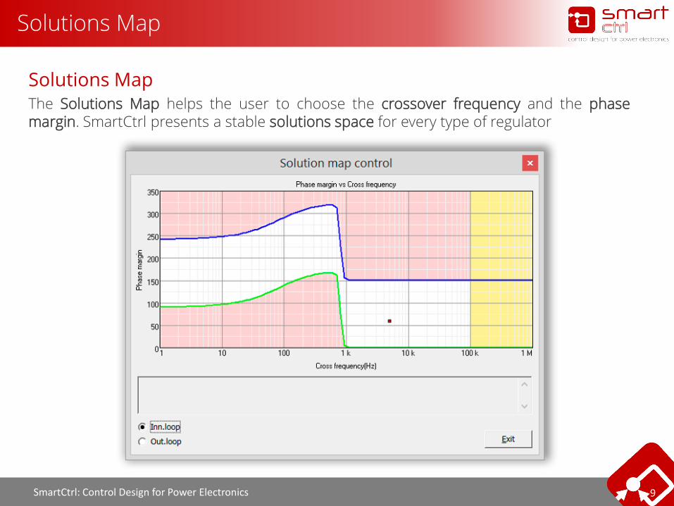
Solutions MapThe Solutions Map helps the user to choose the crossover frequency and the phasemargin. SmartCtrl presents a stable solutions space for every type of regulator

SmartCtrl: Control Design for Power Electronics 10
Waveforms of the Stead-state
Steady-state Waveforms are Plotted
Inductor current and voltage ripple are plotted
The modulating signal output ripple is also plotted
SmartCtrl: Control Design for Power Electronics 11
PSIM Integration
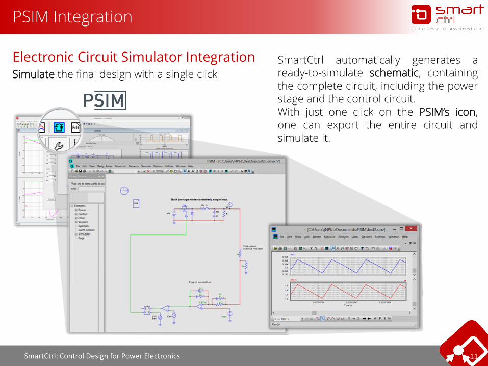
Electronic Circuit Simulator IntegrationSimulate the final design with a single click
SmartCtrl automatically generates aready-to-simulate schematic, containingthe complete circuit, including the powerstage and the control circuit.With just one click on the PSIM’s icon,one can export the entire circuit andsimulate it.
SmartCtrl: Control Design for Power Electronics 12
Capabilities
SmartCtrl: Control Design for Power Electronics 13
Import Frequency
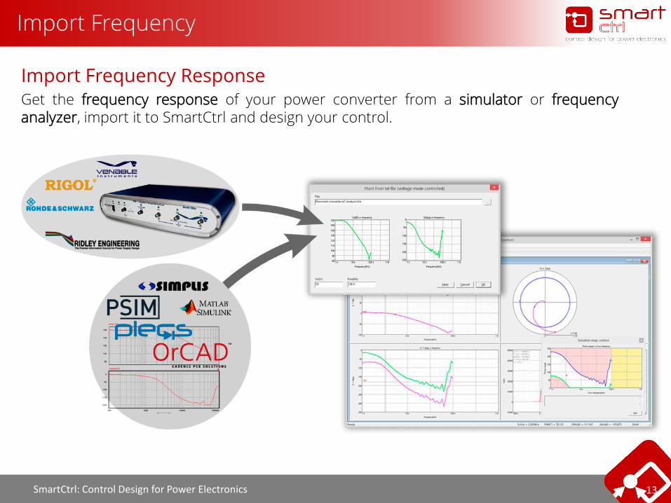
Import Frequency ResponseGet the frequency response of your power converter from a simulator or frequencyanalyzer, import it to SmartCtrl and design your control.
SmartCtrl: Control Design for Power Electronics 14
Import Transfer functions
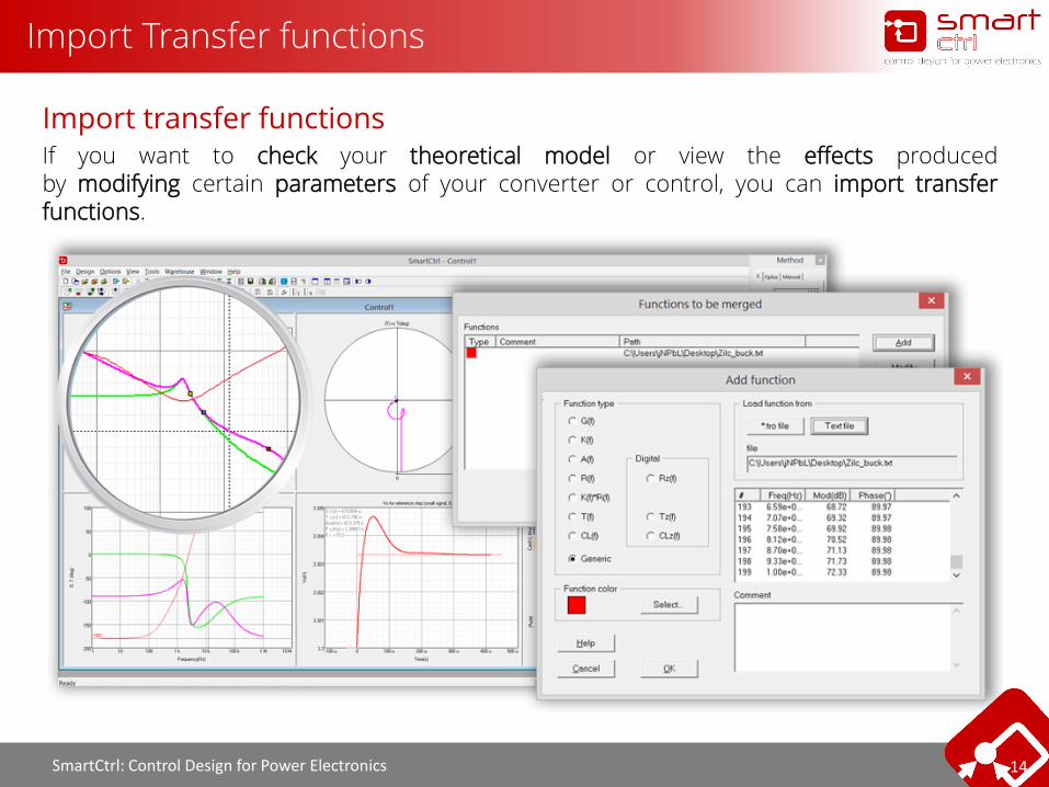
Import transfer functionsIf you want to check your theoretical model or view the effects producedby modifying certain parameters of your converter or control, you can import transferfunctions.

SmartCtrl: Control Design for Power Electronics 15
Export Transfer funcionts
Export Transfer FunctionsRight clicking on any of the sub-screens, you can export the information you need: transfer functions, waveforms and transient responses.

SmartCtrl: Control Design for Power Electronics 16
Audio-susceptibility and input-outpus impedances
Audio-susceptibility and input-output impedancesFor every DC-DC converter and control type, the transfer functions (TF), output voltage to input voltage (Audio-susceptibility) and output voltage to output current (output impedance) are shown as additional Bode Plots.

SmartCtrl: Control Design for Power Electronics 17
Sensibility Analysis
Sensibility AnalysisWith Parametric Sweep you can perform a sensitivity analysis on every parameter of the plant, sensor and regulator. Observe how this changes affect the system. Data is real time updated.
- Input and output voltages- Converter inductance, filter capacitor, cap ESR, etc.- Output power- Switching frequency- Sensor gain and bandwidth- Regulator resistors and capacitors

SmartCtrl: Control Design for Power Electronics 18
Digital Control
Get the Digital ControlThe key features of the Digital Control module are the following:
- Digital effects (DEFs) such as sampling frequency, DPWM delays, and rounding effects dueto the limited bits number of compensator coefficients are considered.
- New Bode plots considering DEFs are shown.- Sensitivity analysis of DEFs can be performed.- The designed digital compensator can be exported to PSIM in z-domain format.

SmartCtrl: Control Design for Power Electronics 19
DC-DC Converters
Topologies and Control ModesIn SmartCtrl you can design the control for a generic converter or use a predefined topology.
The predifined topologies are:
- Forward converter- Flyback converter- Buck converter- Boost converter- Buck-boost converter
For each predefined topologyor generic converter you can choose the following controls:
- Voltage mode control- Average current mode control- Peak current mode control
SmartCtrl: Control Design for Power Electronics 20
PFC Boost Converters
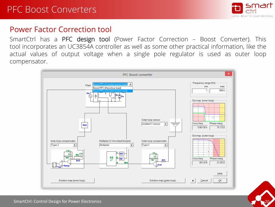
Power Factor Correction toolSmartCtrl has a PFC design tool (Power Factor Correction – Boost Converter). Thistool incorporates an UC3854A controller as well as some other practical information, like theactual values of output voltage when a single pole regulator is used as outer loopcompensator.
SmartCtrl: Control Design for Power Electronics 21
Equations Editor
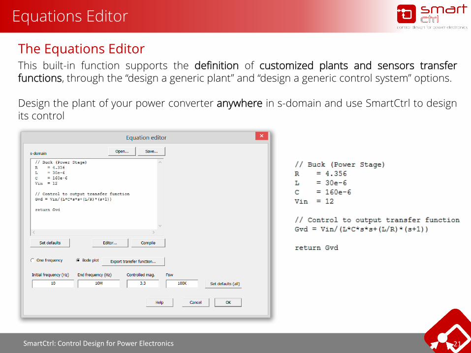
The Equations EditorThis built-in function supports the definition of customized plants and sensors transferfunctions, through the “design a generic plant” and “design a generic control system” options.
Design the plant of your power converter anywhere in s-domain and use SmartCtrl to designits control
SmartCtrl: Control Design for Power Electronics 22
Application Examples

SmartCtrl: Control Design for Power Electronics 23
PFC Boost Converter

SmartCtrl: Control Design for Power Electronics 24
PFC Boost Converter
Boost PFC Converter Control Loops designIn this example it will be designed, step by step, the control loops of a PFC (power factor correction) boostconverter, from SmartCtrl to obtain a complete PSIM’s schematic
Inner Loop (Current Loop)
Outer Loop (Voltage Loop)

SmartCtrl: Control Design for Power Electronics 25
PFC Boost Converter
PFC Boost specificationsIn SmartCtrl it is possible to design two types of Boot PFC:
- Constant Power Load (CPL): as a DC-DC Converter- Resistive Load
and its control could be based on:
- generic multiplier- UC3854A multiplier
The PFC Boost specs in this example will be:

SmartCtrl: Control Design for Power Electronics 26
PFC Boost Converter
SmartCtrl Compensator TypesFor the design of the current loop, the plant is calculated as a DC/DC converter for a certain operatingpoint, that is specified in the line angle wta(º).
Magnitude plot
SmartCtrl: Control Design for Power Electronics 27
PFC Boost Converter
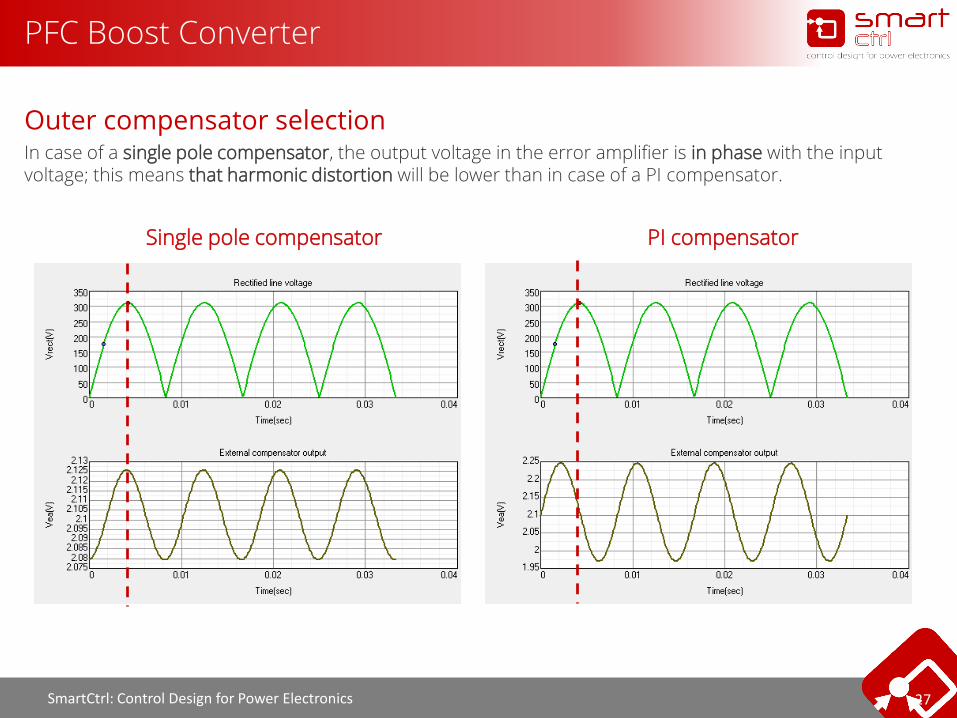
Outer compensator selectionIn case of a single pole compensator, the output voltage in the error amplifier is in phase with the input voltage; this means that harmonic distortion will be lower than in case of a PI compensator.
Single pole compensator PI compensator
SmartCtrl: Control Design for Power Electronics 28
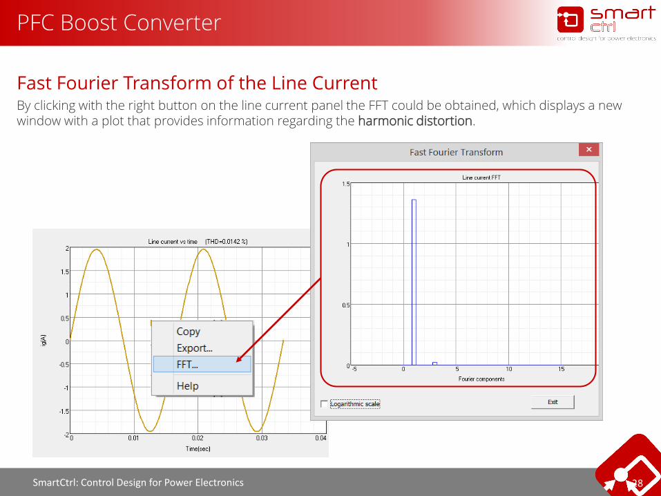
PFC Boost Converter
Fast Fourier Transform of the Line CurrentBy clicking with the right button on the line current panel the FFT could be obtained, which displays a new window with a plot that provides information regarding the harmonic distortion.

SmartCtrl: Control Design for Power Electronics 29
Resonant Converter

SmartCtrl: Control Design for Power Electronics 30
Resonat Converter
Resonant Converter Control Loop DesignOne of the main purposes of this example is to illustrate that the resonant converter can be representedby the imported AC sweep results from PSIM, and the control loop of the resonant converter can bedesigned using SmartCtrl.
1. Perform AC analysis in PSIM

SmartCtrl: Control Design for Power Electronics 31
Resonat Converter
Switching FrequencyTo find out the Fsw of the resonant convert it has been simulated in open loop mode (PSIM simulation).Output voltage is shown below:
Fsw ≈ 124 KHz (T ≈ 8u)

SmartCtrl: Control Design for Power Electronics 32
Single Phase Inverter
SmartCtrl: Control Design for Power Electronics 33
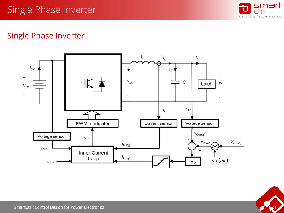
Single Phase Inverter
Single Phase Inverter
L
Load
+
-
vO
iO
iC
iL
C
PWM modulator
vcon
vDCm
tsinRV
vO
+
VO ref p
-
IL ref
vO ref
vO med
iL avg
+
VDC
-
iDC
iL
vO m
+
-
vinv
Voltage sensor
Current sensor
Inner Current
Loop
Voltage sensor
SmartCtrl: Control Design for Power Electronics 34
Thank you very much for your attention
Korea June 2015