present status of paloma facility (technofusión) f.l. tabarés, j.a. ferreira
TRANSCRIPT

Present status of PALOMA Facility (TechnoFusión)
F.L. Tabarés, J.A. Ferreira

Owner: consortium between Madrid Regional government and National Government, based on the technical expertise from CIEMAT and UPM
It has to be a Facility, open to Spanish and European users
It has to be a Facility, i.e. should be based on large-scale equipment and infrastructure not affordable for small research groups
The coordination with the European Fusion Programme must be assured
TechnoFusion Project: Idea

To increase the Spanish involvement in the International Fusion Program
To develop the Spanish technology It should be useful in other research and
technological areas
Whereas ITER construction is mainly based on today´s technology the focus of TechnoFusion will be on: Development of technologies to be used in ITER
at later stage Technology and basic understanding for the next
step (DEMO) R&D complementing the research in ITER
TechnoFusion Project: Objectives

R&D Areas of TechnoFusionMaterials
Irradiation
Plasma/wall
Interaction
Liquid Metals
Technologies
Remote Handling
Characterization
Techniques
Materials Production
& Processing
Computational
Simulation

3 Locations: Getafe (South Madrid)
Getafe I
Getafe II
Remote handling: Big prototipes
Material irradiationLiquid Metal TechnologiesRemote handling under irradiationCharacterization techniquesComputational simulationAdministration

3 Locations: Leganés (South Madrid)
LeganésMaterial Production and ProcessingCharacterization Techniques

3 Locations: CIEMAT
11-12
20F
Madrid I
Madrid II
Ion accelerators (Material irradiation)Characterization techniques
Plasma-Wall InteractionCharacterization techniques

24th January 2011: Sign of the agreement for the foundation of TechnoFusion Consortium by CIEMAT, UC3M and UPM
Last News

Material Irradiation Area
GOAL To reproduce neutron effects using accelerators
1. H and He generated in fusion (1 ppm/week of He in Fe) using implantation of H and He
2. Displacements (dpa’s) using high energy ions of the target material
Triple beam irradiation zone Single beam operation to
irradiate under high magnetic field
Several simple/double lines to irradiate at different temperatures (“in beam” measurements)
MAIN CONDITIONS:• Reach IFMIF values of
irradiation (0,1 dpa/week)• Reach He/dpa ratios ~5 - 11
1.E-03
1.E-02
1.E-01
1.E+00
1.E+01
1.E+02
1.E+03
1.E-03 1.E-02 1.E-01 1.E+00 1.E+01 1.E+02
Desplazamientos [DPA/ semana]H
e[ap
pm/s
eman
a]
HTTR
PWD
JMTRJOYO
ITER
DEMOIFMIF (MF)
IFMIF (HF)
Fe
BOR60
XADS (1MW)
ESS
HFR Petten(position f8)
SPIRAL 2
SNS (p+n)
BR2 Mol
TECHNOFUSI ON

Heavy Ion AcceleratorCyclotron
k=110
Light Ion Accelerat
or4 MV
Light Ion Accelerato
r 6 MV
Irradiated
Matrerial
Depth
(µm)Ion
Energy
(MeV)Ion
Energy
(MeV)Ion
Energy
(MeV)
Fe (7.8 g/cm3)
26.6Fe
385 H 2.5 He 10
W (19.3 g/cm3)
10.1W
373 H 1.6 He 6
C (2.3 g/cm3)
148C
96 H 4.5 He 18
SiO2 (2.2 g/cm3)
175Si
337 H 4.6 He 18
SiC (3.2 g/cm3)
122.4
Si337 H 4.6
He 18
SiC (3.2 g/cm3)
122.4
Si337 D 4.6
He 18
Material Irradiation
104
105
106
107
108
109
10-5 0,001 0,1 10 1000
CW
Act
ivity
(B
q)t (days)

Conceptual design in progress !!
Linear accelerators: commercially available, but some issues has still to be solved in the near term, as the ion sources (types, currents,…)
Cyclotron : Isochronous multi-ion (complex!!). Detailed design needed: Possibly SC type. Estimations are in progress
External Collaborations has been created (MIT, GANIL…) but finally a constructor will have to be found
Common issues: Components of transport lines
Neutralizer
Beam energy degrader…
Probably some prototypes will be needed
Material Irradiation Area
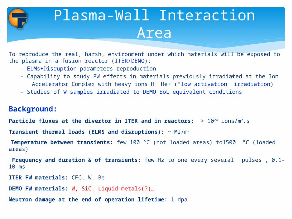
To reproduce the real, harsh, environment under which materials will be exposed to the plasma in a fusion reactor (ITER/DEMO):
- ELMs+Disruption parameters reproduction - Capability to study PW effects in materials previously irradiated at the Ion
Accelerator Complex with heavy ions H+ He+ (“low activation” irradiation) - Studies of W samples irradiated to DEMO EoL equivalent conditions
Background:
Particle fluxes at the divertor in ITER and in reactors: > 1024 ions/m2.s
Transient thermal loads (ELMS and disruptions): ~ MJ/m2
Temperature between transients: few 100 ºC (not loaded areas) to1500 ºC (loaded areas)
Frequency and duration & of transients: few Hz to one every several pulses , 0.1-10 ms
ITER FW materials: CFC, W, Be
DEMO FW materials: W, SiC, Liquid metals(?)….
Neutron damage at the end of operation lifetime: 1 dpa
Plasma-Wall Interaction Area
Plasma-Wall Interaction Area
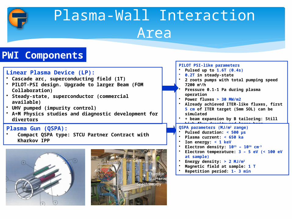
PWI Components
Linear Plasma Device (LP):• Cascade arc, superconducting field (1T)• PILOT-PSI design. Upgrade to larger Beam (FOM Collaboration)• Steady-state, superconductor (commercial available)• UHV pumped (impurity control)• A+M Physics studies and diagnostic development for divertors
PILOT PSI-like parameters • Pulsed up to 1.6T (0.4s)• 0.2T in steady-state• 2 roots pumps with total pumping speed 7200 m3/h• Pressure 0.1-1 Pa during plasma operation• Power fluxes > 30 MW/m2• Already achieved ITER-like fluxes, first 5 cm of
ITER target (5mm SOL) can be simulated• + beam expansion by B tailoring: Still high flux
density and large beam
Plasma Gun (QSPA):• Compact QSPA type: STCU Partner Contract with Kharkov IPP
QSPA parameters (MJ/m2 range) • Pulsed duration: < 500 µs• Plasma current: < 650 ka• Ion energy: < 1 keV• Electron density: 1015 – 1016 cm-3
• Electron temperature: 3 – 5 eV (< 100 eV at sample)• Energy density: > 2 MJ/m2
• Magnetic field at sample: 1 T• Repetition period: 1- 3 min

Plasma Gun (QSPA)
Design Completed by Kharkov IPP team in collaboration with CIEMAT
Ready for prototyping
Linear device
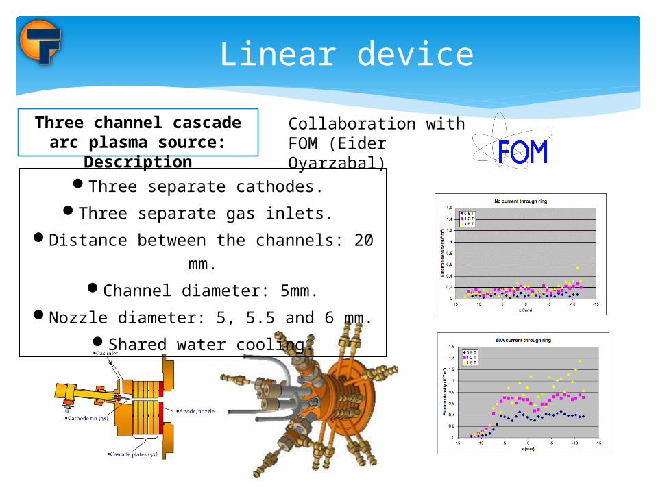
Three channel cascade arc plasma source:
DescriptionThree separate cathodes.
Three separate gas inlets.
Distance between the channels: 20 mm.
Channel diameter: 5mm.
Nozzle diameter: 5, 5.5 and 6 mm.
Shared water cooling.
Collaboration with FOM (Eider Oyarzabal)

QSPA needs an expansion chamber pumping (incompatible with coils)
Interconnection of both machines
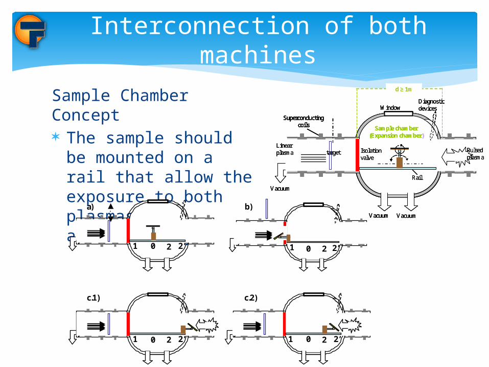
Sample Chamber Concept The sample should be
mounted on a rail that allow the exposure to both plasmas alternatively
Interconnection of both machines
Vacuum Vacuum
DiagnosticdevicesWindow
Sample chamber(Expansion chamber)
d ≥ 1m
Linearplasma target Isolation
valve
Vacuum
Rail
Superconductingcoils
Pulsedplasma
Vacuum Vacuum
DiagnosticdevicesWindow
Sample chamber(Expansion chamber)
d ≥ 1m
Linearplasma target Isolation
valve
Vacuum
Rail
Superconductingcoils
Pulsedplasma
Vacuum Vacuum
DiagnosticdevicesWindow
Sample chamber(Expansion chamber)
d ≥ 1m
Linearplasma target Isolation
valve
Vacuum
Rail
Superconductingcoils
Superconductingcoils
Pulsedplasma
2 1 2’ 0
a)
2 1 2’ 0
c.1)
2 1 2’ 0
b)
2 1 2’ 0
c.2)

NbTi coils cooled by cryocoolers
Coil design
Material Volume SurfaceCoil NbTi 6,4e-4 m3 0,10 m2
Conductor C10200 (OF copper)
5,0e-4 m3 0,14 m2
Heat shield C10200 8,0e-4 m3 0,27 m2
Outer cryostat
304L MLI interior
1,0e-3 m3 0,36 m2
Table 2. Geometrical characteristics

Technology based on existing devices The most demanding part involving the
integration of both systems Waiting for funding…
Conclusions