prepared for the use of epartment water … · united states department of the interior ... intake...
TRANSCRIPT

()
PREPARED FOR THE USE OF EPARTMENT OF WATER RESOURCES, STATE OF CALIFORNIA
UNITED STATES DEPARTMENT OF THE INTERIOR
BUREAU OF RECLAMATION
HYDRAULIC MODEL STUDIES OF THE OROVILLE DAM POWERPLANT
INTAKE STRUCTURES--CALIFORNIA DEPARTMENT OF WATER
RESOURCES--STATE OF CALIFORNIA
Report No. Hyd-509
Hydraulics Branch DIVISION OF RESEARCH
OFFICE OF CHIEF ENGINEER DENVER, COLORADO
June 1 5 , 19 6 5

UNITED STATES DEPARTMENT OF THE INTERIOR
BUREAU OF RECLAMATION OFF1CE OF CHIEF ENGINEER
IN REPLY REFER TO: D-293
BUILDING !53, DENVER FEDERAL CENTER DENVER. COLORADO 80225
June 15, 1965
Mr. William E. Warne, Director Department of Water Resources State of California Sacramento, California 95802
Dear Mr. Warne:
I am pleased to submit Hydraulics Branch Report No. Hyd-509 which constitutes our final report on the hydraulic model studies for the intake structures for Oroville Dam Powerplant. I believe this report will satisfy the requirements of your office for a comprehensive discussion of the extensive test program.
Enclosure
Sincerely yours,
B; P. Bellport Chief Engineer

PREFACE
Hydraulic model studies of features of Oroville Dam and Powerplant were conducted in the Hydraulic Laboratory in Denver, Colorado. The studies were made under Contract No. 14-06-D-3399 between the California Department of Water Resources and the Bureau of Reclamation.
The designs were conceived and prepared by Department of Water Resources engineers. Model studies verified the general adequacy of the designs and also led to modifications needed to obtain more satisfactory performance. The high degree of cooperation that existed between the staffs of the two organizations helped materially in speeding final results.
During the course of the studies Messrs. H. G. Dewey, Jr., D. P. Thayer, and other members of the California staff visited the laboratory to observe the tests and discuss model results. Mr. K. G. Bucher of the Fluid Mechanics Section of the Department was assigned to the Bureau Laboratory for training and for assisting in the test program. Mr. G. W. Dukleth provided liaison between the Bureau and the Department.
I
r
I
\ )I
I \

CONTENTS
Abstract .......................................... . Purpose .......................................... . Conclusions ....................................... . Introduction ....................................... .
iii 1 1 3
Design I . . . . . . . . . . . . . . . . . . . . . . . . . . . . . . . . . . . . . . . . . 4 Design II . . . . . . . . . . . . . . . . . . . . . . . . . . . . . . . . . . . . . . . . 4 Design III .. -. . . . . . . . . . . . . . . . . . . . . . . . . . . . . . . . . . . . . 4 General . . . . . . . . . . . . . . . . . . . . . . . . . . . . . . . . . . . . . . . . . 5
Models ........... ~ . . . . . . . . . . . . . . . . . . . . . . . . . . . . . . . . . 5
Design I ·. . . . . . . . . . . . . . . . . . . . . . . . . . . . . . . . . . . . . . . . . 5 Design II . . . . . . . . . . . . . . . . . . . . . . . . . . . . . . . . . . . . . . . . 7 Design III • . . . . . . . . . . . . . . . . . . . . . . . . . . . . . . . . . . . . . . 7
Investigation . . . . . . . . . . . . . . . . . . . . . . . . . . . . . . . . • . . . . . . . 7
Design I .. : . . . . . . . . . . . . . . . . . . . . . . . . . . . . . . . . . . . . . . 7
Head loss ... ·. . . . . . . . . . . . . . . . . . . . . . . . . . . . . . . . . . 7 Vortex study. . . . . . . . . . . . . . . . . . . • . . . . . . . . . . . . . . . 8 Shutter vibration . . . . . . . . . . . . . . . . . . . . . . . . . . . . . . . 8 General pressures· . . . . . . . . . . . . . . . . . . . . . . . . . . . . . 9
Design II . . . . . . . . . . . . . . . . . . . . . . . . . . . . . . . . . . . . . . . . . 9
Head loss . .-................................... 10 Vortex study . . . . . . . . . . . . . . . . . . . . . . . . . . . . . . . . . • . 1 O Differential pressures across shutters . . . . . . . . . . . 11 General pressures . . . . . . . . . . . . . . . . . . . . . . . . . . . . . 12
Design III ........................... : . . . . . . . . . . . . 12
Channel beams . . . . . . . . . . . . . . . . . . . . . . . . . . . . . . . . 12 Leading-edge shapes . . . . . . . . . . . . . . . . . . . . . . . . • . . . 13
Bibliography ....................................... .
Differential Pressures Across Control Shutters,
14
Table
Design I. . . . . . . . . . . . . . . . . . . . . . . . . . . . . . . . . . . . . . . . . . . 1 Manometer Pressures Along Channel and Penstock
Transitions, Design I.. . . . . . . . . . . . . . . . . . . . . . . . . . . . . . 2
i

CONTENTS- -Continued
Table
Submergence Test Observations . . . . . . . . . . . . . . . . . . . . . . . 3 Manometer Pressures Along Channel and Penstock
Transitions, Design II ... ·. . . . . . . . . . . . . . . . . . . . . . . . . . . 4
Location Map ...................................... . Project Map ....................................... . Site Plan .......................................... . Plan and Profile-Intake System ...................... . Plan and Profile-Design I ........................... . Suggested Shutter Design ........................... . Structural Details-Design II ......................... . Structural Layout ................................... . Channel Transition-Design I ......................... . Pens tock Transition ........................ 1 •••••••••
Intake Gate and Gate Operator ....................... . Discharge Rating Curve ............................. . Model Layout ...................................... . Construction of Headbox_ and Topography ............. . General Views of Model-Design I .................... . Semicylindrical Shutters-Design I ................... . General Views of Trashrack Section and Intake
Model-Design II .................................. . Comparison of Cross-Sections of Design II and III ..... . Segmented Arch Trashracks-Design III ............... . Elevation of Intake Structure and Definition of
Head Loss Measurement .... · ....................... . Head Loss Tests-Design I ........................... . Vortex Study-Design I .............................. . Conditions and Shutter Positions for Vibration Study .... . Piezometer Locations-Design I ...................... . Head Loss and Loss Coefficients-Design II ............ . Base Deflector-Design II ............................ . Vortex Study ...................................... . Differential Pressures Across Shutters-Design II ...... . Differential Pressures-Design II ..................... . Piezometer Locations-Design II ...................... . Head Loss and Differential Pressures, 6 Shutters-
Design III ........................................ . Effect of Gap Between Shutter and Channel Beam ....... . Leading Edge Head Loss-Design III .................. . Differential Pressures Across 1, 3 and 4 Shutters-
Design III ........................................ .
ii
Figure
1 2 3 4 5 6 7 8 9
10 11 12 13 14 15 16
17 18 19
20 21 22 23 24 25 26 27 28 29 30
31 32 33
34

ABSTRACT
Hydraulic model studies helped determine head losses, differential pressures, vortex action, and general pressures for three proposed designs for the intake structure of the Oroville Dam underground powerplant. Agriculture and fish propagation downstream from the dam require control of the temperature of water released through the powerplant. This control is accomplished by withdrawing water from selected reservoir depths through ports or opened .shutters placed along intake structures which slope up the side of the reservoir. Design I consisted of 650-footlong trapezoidal channel with semicircular covering shells, a 60-footlong trashrack-covered port at the base, and five additional 40-focit-long ports Flow through each port was controlled by thin semicylindrical shutters. The design was abandoned because of possible instability of the semicylindrical shutters and complicated, submerged mechanisms necessary to engage, move, and latch the shutters. Design II consisted of sloping channels with larger trapezoidal cross sections and continuous arched trashracks the full length of the structures. Under the trashracks, flat 40-foot-long by 45-foot-wide control shutters covered the intake channels. The shutters could be removed from the channels or reinstalled as reservoir level or temperature requirements changed. Design II was tested thoroughly and accepted for prototype use. However, unexpected foundation problems required structural modifications, culminating in Design III. This ,design utilized rectangular channels with lighter trashrack arches supplemented by tension beams across the channel at the bas·e of each arch. Design III was adopted.
DESCRIPTORS-- ,:,hydraulics/ ,:,head losses/ ,:,pressures/ hydraulic models/ flow control/ trapezoidal channels/ ,:,vortices/ hydraulic structures I underground powerplants / intake gates/ trashracks / ,:,intake structures/ temperature/ model tests/ temperature control/ inlets/ research and development/ fish/ agriculture/ ports IDENTIFIERS-- >!<Oroville Dam powerplant/ sloping intake structures/ California/ reentrant inlets/ shutters/ hydraulic design/ temperature control shutters
iii

UNITED STA TES DEPARTMENT OF THE INTERIOR
BUREAU OF RECLAMATION
Office of Chief Engineer Division of Research Hydraulics Branch Denver, Colorado June 15, 1965
Report No. Hyd-509 Author: K. G. Bucher Checked by: W. P. Simmons Reviewed by: W. E. Wagner Submitted by: H. M. Martin
HYDRAULIC MODEL STUDIES OF THE OROVILLE DAM POWERPLANT INTAKE STRUCTURES--CALIFORNIA DEPARTMENT OF WATER
RESOURCES--STA TE OF CALIFORNIA
PURPOSE
Model studies were made to investigate pressure conditions and head losses in the Oroville Powerplant intake structures, differential pressures acting on the control shutters, and vortex action in the reservoir above the intakes.
CONCLUSIONS
Design I
1. The head loss through the initial design was 4. 2 feet of water at the maximum discharge of 8,600 cfs (cubic feet per second) in one intake.
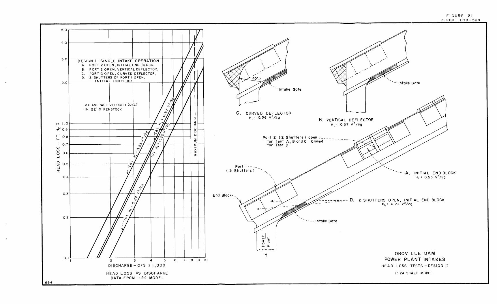
2. The addition of a deflector to eliminate the recess at the end block at the bottom of the intake channel reduced head losses by 30 percent or 1. 3 feet of water (Figure 21).
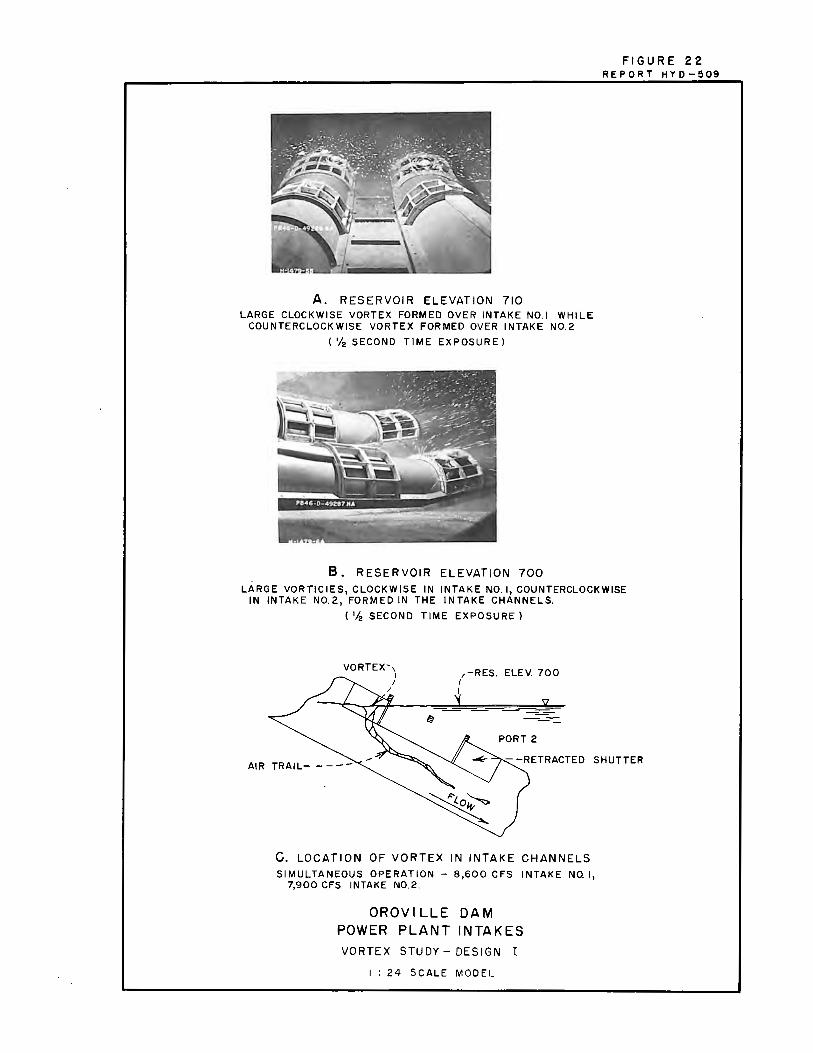
3. A shallow vortex formed above Port 2 for submergences up to 118 feet. The vortex did not draw air until the water level was low enough to expose the crown of the port (Figure 22).
4. Tests indicated that long-period pressure reversals were present on the semicylindrical temperature control shutters (Table 1).
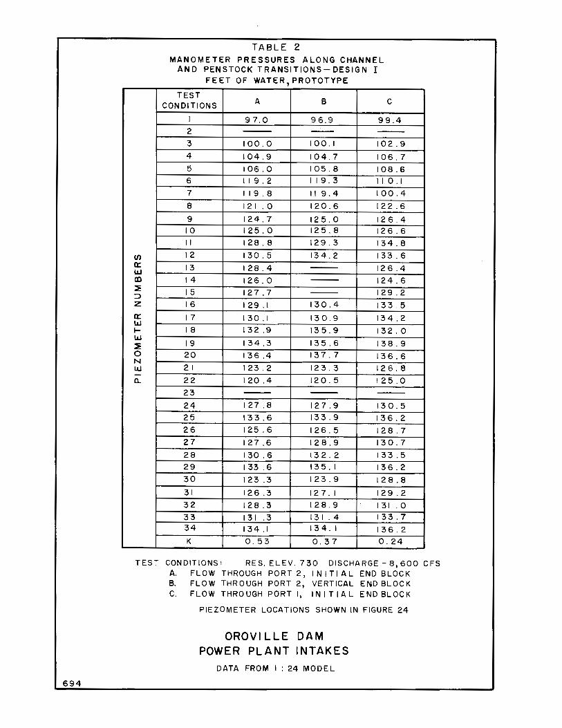
5. All pressures measured along the channel transition and penstock transition were positive and, hence, satisfactory (Table 2).
6. Design I was abandoned at the recommendation of the Board of Consultants due to questions about stability of the lightweight shutters and the complicated handling equipment.
Design II
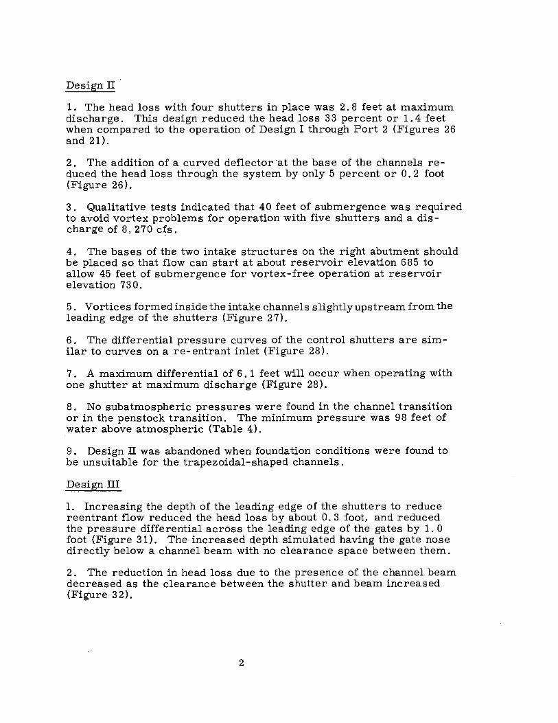
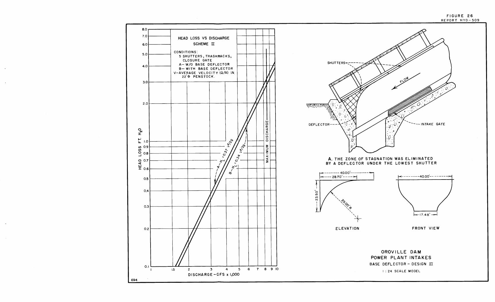
1. The head loss with four shutters in place was 2. 8 feet at maximum discharge. This design reduced the head loss 33 percent or 1. 4 feet when compared to the operation of Design I through Port 2 (Figures 26 and 21).
2. The addition of a curved deflector ·at the base of the channels reduced the head loss through the system by only 5 percent or O. 2 foot (Figure 26).
3. Qualitative tests indicated that 40 feet of submergence was required to avoid vortex problems for operation with five shutters and a discharge of 8, 270 c{s.
4. The bases of the two intake structures on the right abutment should be placed so that flow can start at about reservoir elevation 685 to allow 45 feet of submergence for vortex-free operation at reservoir elevation 730.
5. Vortices formed inside the intake channels slightly upstream from the leading edge of the shutters (Figure 27).
6. The differential pressure curves of the control shutters are similar to curves on a re-entrant inlet (Figure 28).
7. A maximum differential of 6. 1 feet will occur when operating with one shutter at maximum discharge (Figure 28).
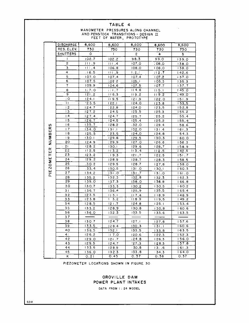
8. No subatmospheric pressures were found in the channel transition or in the penstock transition. The minimum pressure was 98 feet of water above atmospheric (Table 4).
9. Design II was abandoned when foundation conditions were found to be unsuitable for the trapezoidal-shaped channels.
Design III
1. Increasing the depth of the leading edge of the shutters to reduce reentrant flow reduced the head loss by about O. 3 foot, and reduced the pressure differential across the leading edge of the gates by 1. 0 foot (Figure 31). The increased depth simulated having the gate nose directly below a channel beam with no clearance space between them.
2. The reduction in head loss due to the presence of the channel beam decreased as the clearance between the shutter and beam increased (Figure 32).
2
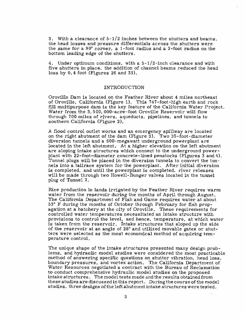
3 . With a clearance of 5-1 / 2 inches between the shutters and beams, the head losses and pressure differentials across the shutters were the same for a 90° corner, a 1-foot radius and a 2-foot radius on the bottom leading edge of the shutters.
4. Under optimum conditions, with a 5-1/2-inch clearance and with five shutters in place, the addition of channel beams reduced the head loss by O. 4 foot (Figures 26 and 33).
INTRODUCTION
Oroville Dam is located on the Feather River about 4 miles northeast of Oroville, California (Figure 1). This 747-foot-high earth and rock fill multipurpose dam is the key feature of the California Water Project. Water from the 3, 500, 000-acre-foot Oroville Reservoir will flow through 700 miles of rivers, aqueducts, pipelines, and tunnels to southern California (Figure 2).
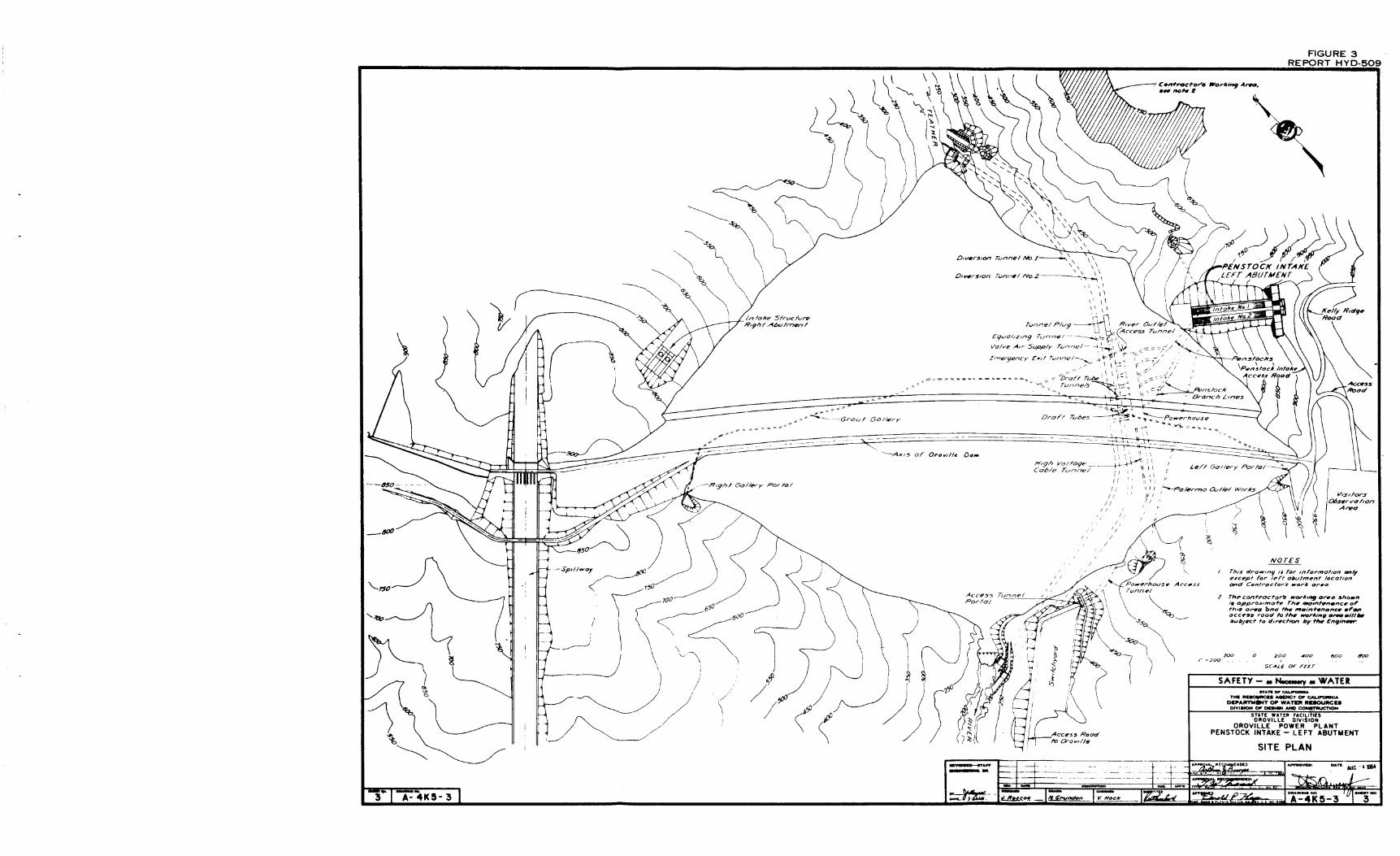
A flood control outlet works and an emergency spillway are located on the right abutment of the dam (Figure 3). Two 35-foot-diameter diversion tunnels and a 600-megawatt underground powerplant are located in the left abutment. At a higher elevation on the left abutment are sloping intake structures which connect to the underground powerplant with 22-foot-diameter concrete-lined penstocks (Figures 3 and 4). Tunnel plugs will be placed in the diversion tunnels to convert the tunnels into a tailrace system for the powerplant. After initial diversion is completed, and until the powerplant is completed, river releases will be made through two Howell-Bunger valves located in the tunnel plug of Tunnel 2.
Rice production in lands irrigated by the Feather River requires warm water from the reservoir during the months of April through August. The California Department of Fish and Game requires water at about 53° F during the· months of October through February for fish propagation at a hatchery at the city of Oroville. These requirements for controlled water temperatures necessitated an intake structure with provisions to control the level, and hence, temperature, at which water is taken from the reservoir. Intake structures that sloped up the side of the reservoir at an angle of 28° and utilized movable gates or shutters were selected as the most economical method of acquiring temperature control.
The unique shape of the intake structures presented many design problems, and hydraulic model studies were considered the most practicable method of answering specific questions on shutter vibration, head loss, boundary pressures, and vortex action. The California Department of Water Resources negotiated a contract with the Bureau of Reclamation to conduct comprehensive hydraulic model studies on the proposed intake structures. The model tests ma.de and the results obtained from these studies ar_e discussed in this report. During the course of the model studies, three designs of the left abutment intake structures were tested.
3

Design I
In cross section, the lower half of each channel was essentially trapezoidal and the upper half semicircular (Figure 5). Six trashrackcovered ports were located along each intake. The lowest port was 60 feet long. The 84-foot space to the next port was covered by a semicylindrical concrete shell. The remaining five ports were 40 feet long, spaced 80 feet center to center, with 40 feet of concrete shell between adjacent ports. The port could be closed by movable semicylindrical shutters (Figures 5 and 16). Two 20-foot-long shutters were used in each 40-foot port and three 20-foot-long shutters were used in the 60-foot port. When a 40-foot port was to be opened, a mechanical operator would engage the upper shutter and move it up the intake into position under the concrete shell with the end of the shutter flush with the edge of the port. The operator would then latch the shutter in place. Next, it would move to the second shutter and move it down the intake to a similar position under the shell and lock it in place. When the 60-foot port was to be opened, the operator would move all three shutters up the intake under the 84-foot-long concrete shell.
Design II
The initial concept of this design proposed a larger open-topped trapezoidal channel with flat shutters along the entire axis of the intake (Figure 6). A continuous trashrack was also provided. The shutters were coupled together with rods that telescoped into the shutters. When the uppermost shutter was drawn uphill, the rod slack was taken up, leaving about a 40-foot opening between it and the following shutter. Withdrawal of successive shutters would continue as the reservoir receded or if an opening at a lower elevation was desired. Full withdrawal of the shutters required hoisting trackage almost triple the length of the intake. After study, the Department of Water Resources adopted the basic idea of this proposal, but the shutter "train" was abandoned because of length of trackage and size of the hoisting mechanism required to draw the shutters up the intake.
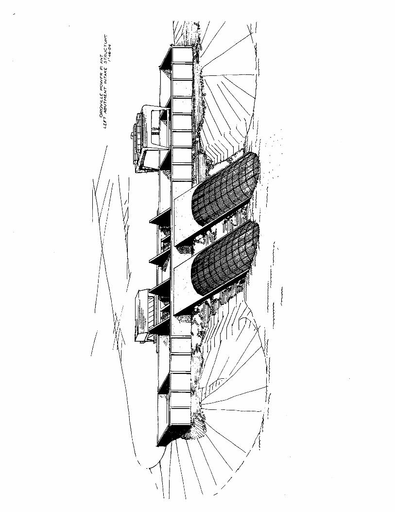
The intake was redesigned with shutters that would be individually hoisted up the structure as the water s1._1rface receded or as the temperature requirements changed. The temper.ature control shutters were large flat panels 40 feet long by 45 feet wide. The removed shutters would be stored in bays at the service level of the structure (frontispiece). Design II is shown in Figure 7.
Design Ill
Unexpected foundation conditions uncovered during field excavation required elimination of the sloping walls of the trapezoidal channel of Design II, and the cross section of the channels was changed from
4
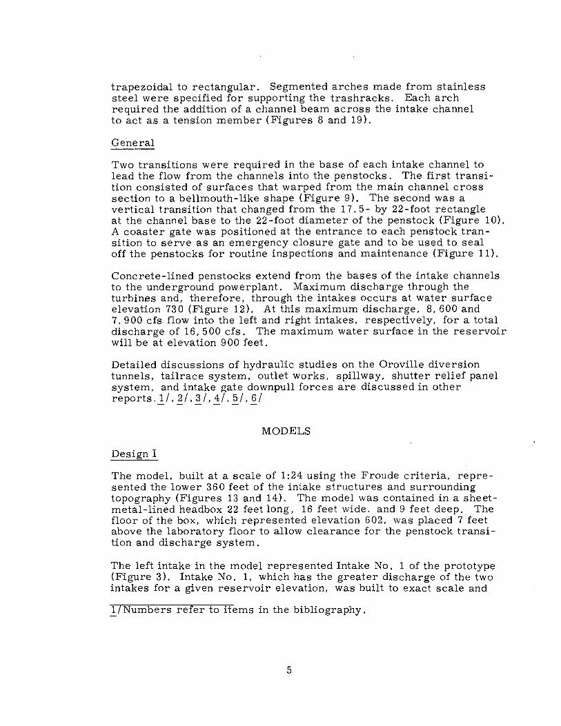
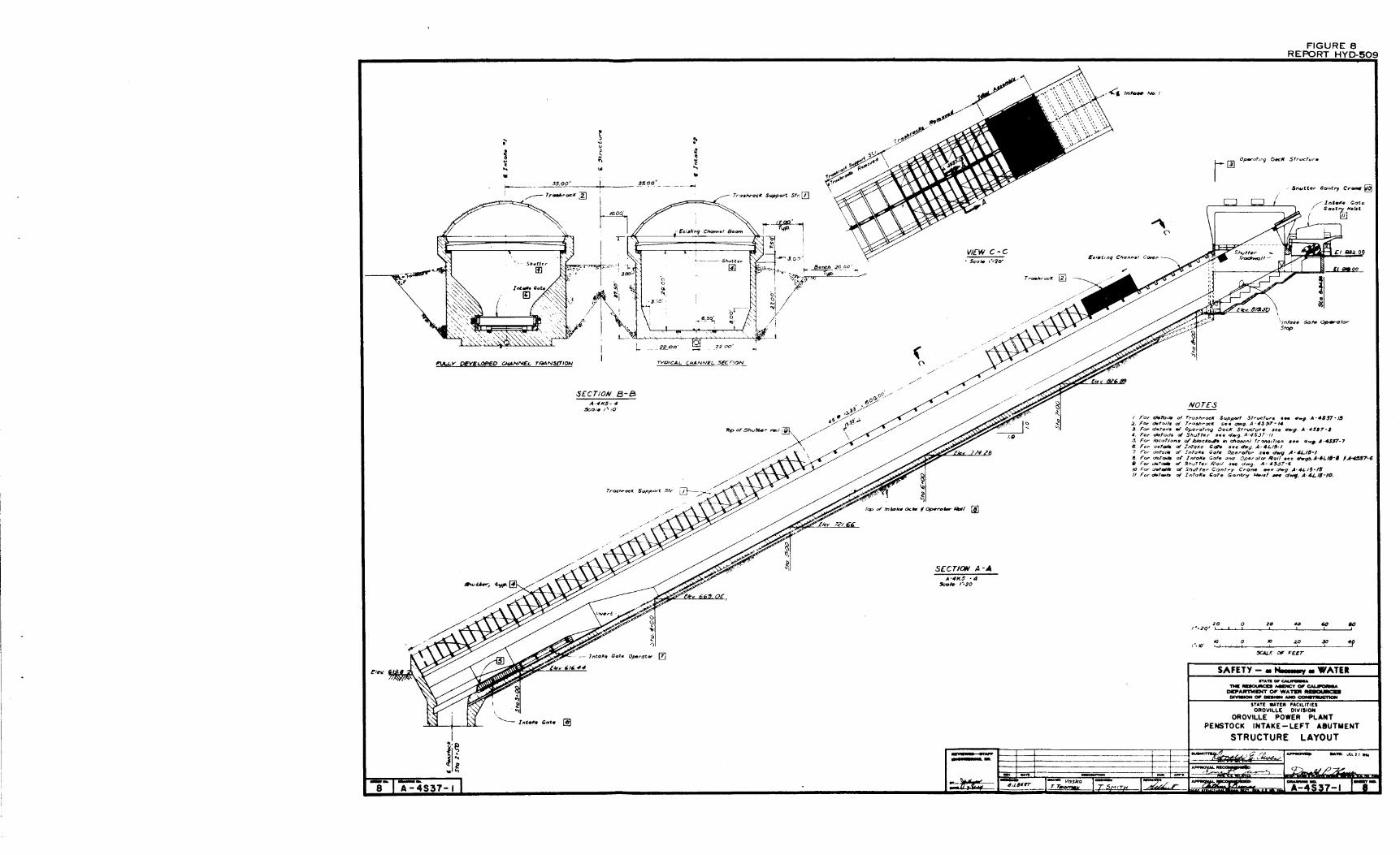
trapezoidal to rectangular. Segmented arches made from stainless steel were specified for supporting the trashracks. Each arch required the addition of a channel beam across the intake channel to act as a tension member (Figures 8 and 19).
General
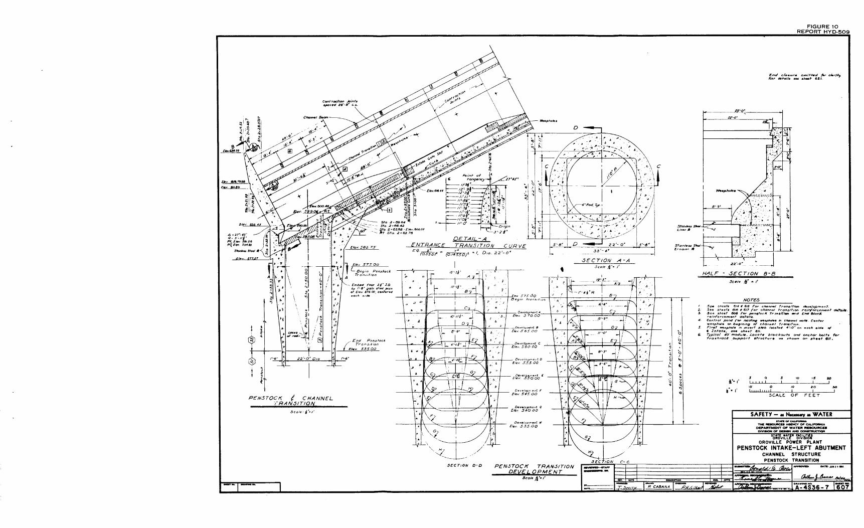
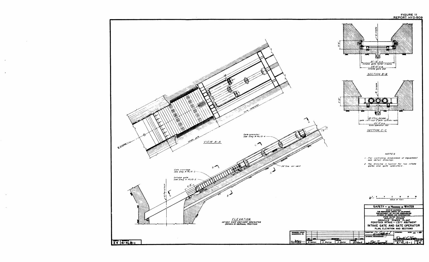
Two transitions were required in the base of each intake channel to lead the flow from the channels into the penstocks. The first transition consisted of surfaces that warped from the main channel cross section to a bellmouth-like shape (Figure 9). The second was a vertical transition that changed from the 17. 5- by 22-foot rectangle at the channel base to the 22-foot diameter of the penstock (Figure 10). A coaster gate was positioned at the entrance to each penstock transition to serve as an emergency closure gate and to be used to seal off the penstocks for routine inspections and maintenance (Figure 11).
Concrete-lined penstocks extend from the bases of the intake channels to the underground powerplant. Maximum discharge through the turbines and, therefore, through the intakes occurs at water surface elevation 730 (Figure 12). At this maximum discharge, 8, 600 and 7, 900 cfs flow into the left and right intakes, respectively, for a total discharge of 16, 500 cfs. The maximum water surface in the reservoir will be at elevation 900 feet.
Detailed discussions of hydraulic studies on the Oroville diversion tunnels, tailrace system, outlet works, spillway, shutter relief panel system, and intake gate downpull forces are discussed in other reports.}),~/,~/, ii, 'E_/, §_/
MODELS
Design I
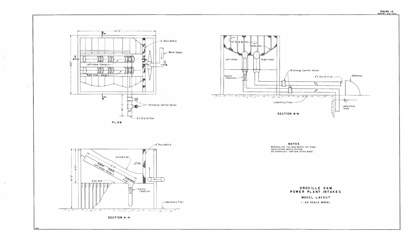
The model, built at a scale of 1:24 using the Froude criteria, represented the lower 360 feet of the intake structures and surrounding topography (Figures 13 and 14). The model was contained in a sheetmetal-lined headbox 22 feet long, 16 feet wide, and 9 feet deep. The floor of the box, which represented elevation 602, was placed 7 feet above the laboratory floor to allow clearance for the penstock transition and discharge system .
The left intake in the model represented Intake No. 1 of the prototype (Figure 3). Intake No. 1, which has the greater discharge of the two intakes for a given reservoir elevation, was built to exact scale and
.!_/Numbers refer to items in the bibliography.
5

was used for detailed testing (Figure 15-A). Included in this structure were the control shutters, intake gate, channel and penstock transitions, and a short length of 22-ioot-diameter penstock.
The trapezoidal and semicircular sections of the intake channel were shaped from galvanized sheet metal and reinforced by heavy gage sheet metal stiffeners. The transition in the lower 150 feet of Channel No. 1 was shaped from waterproofed sugar pine wood. The transition warped from the trapezoidal cross section on the intake channel to the bellmouth-type entrance above the vertical penstock (Figure 9). Removable inserts could be placed at the base of the tower so the effect of different end shapes could be determined. The rectangular portion of the penstock transition was made from galvanized sheet metal and the transition from the rectangular section to the round penstock was made from transparent plastic. Thirty-four piezometers were placed along the channel and penstock transitions (Figure 24).
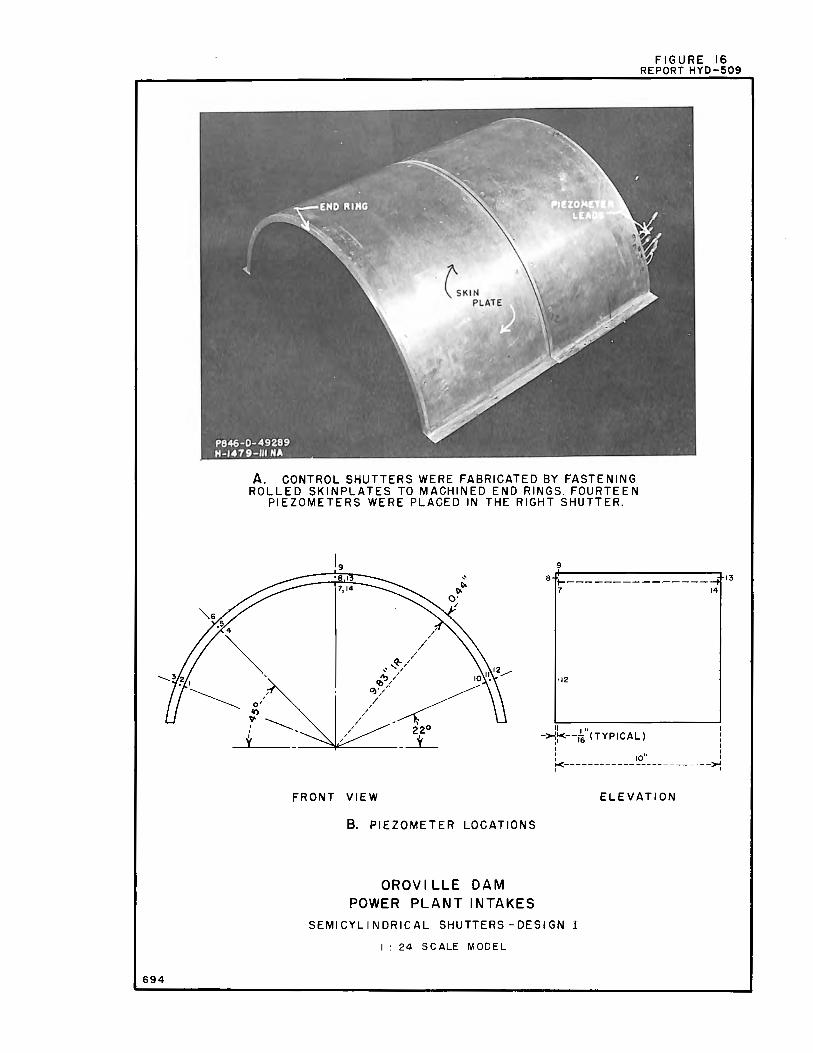
The semicylindrical control shutters for Intake No. 1 were fabricated by fastening rolled No. 16-gage brass skinplates to machined brass end rings (Figure 16-A). Fourteen piezometers were placed in one of the shutters to measure pressures on the shutter when it was placed at various locations under the concrete shell near the edge of the port (Figure 16-B).
The right intake represented Intake No. 2 and was modeled in general shape only (Figure 15-A). It was used when both intakes were operating simultaneously and was fabricated as a cylinder with openings at proper locations to represent intake ports. Trashracks were provided. A hinge was welded to the base of the cylinder so the intake could be tilted up to provide access for piezometer connections underneath.
Topography was constructed by cutting wooden contours and placing them to their appropriate elevation in the headbox. Expanded metal lath was formed over the contours and a 3 / 4-inch layer of concrete was placed over the lath to produce the finished surface (Figure 14-B).
Water was supplied to the model through the central laboratory supply system. Flow rates into the headbox were measured by permanently installed and calibrated Venturi meters. Flow through the model was discharged through two 12-inch pipes, one located below the base of each intake (Figure 13). An orifice plate was calibrated and placed on the end of the discharge pipe of the Intake No. 2. During simultaneous operation, the total \discharge for a specific reservoir elevation for the two intakes was supplied to the headbox; flow through Intake No. 2 was measured by the orifice and throttled to give the appropriate discharge for that intake, the remaining water passed through Intake No. 1.
6
Design II
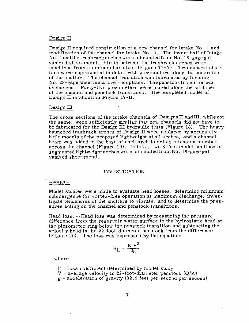
Design II required construction of a new channel for Intake No. 1 and modification of the channel for Intake No. 2. The invert half of Intake No. 1 and thetrashrackarches were fabricated from No. 18-gage galvanized sheet metal. Struts between the trashrack arches were machined from aluminum bar stock (Figure 17-A). Two control shutters were represented in detail with piezometers along the underside of the shutter. The channel transition was fabricated by forming No. 28-gage sheet metal over templates. The penstock transition was unchanged. Forty-five piezometers were placed along the surfaces of the channel and penstock transitions. The completed model of Design II is shown in Figure 1 7-B.
Design III
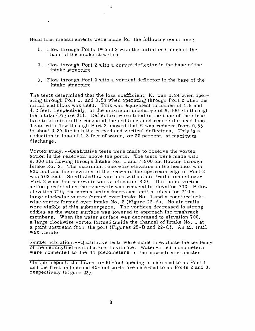
The cross sections of the intake channels of Designs II and III, while not the same, were sufficiently similar that new channels did not have to be fabricated for the Design III hydraulic tests (Figure 18). The heavy haunched trashrack arches of Design II were replaced by accurately built models of the proposed lightweight steel arches, and a channel beam was added to the base of each arch to act as a tension member across the channel (Figure 19). In total, two 3-foot model sections of segmented lightweight arches were fabricated from No. 18-gage galvanized sheet metal.
INVESTIGATION
Design I
Model ·studies were made to evaluate head losses, determine minimum submergenc.e for vortex-free operat10n at maximum discharge, investigate tendencies of the shutters to vibrate, and to determine the pressures acting on the channel and penstock transitions.
Head loss. - -Head loss was determined by measuring the pressure difference from the reservoir water surface to the hydrostatic head at the piezometer ring below the penstock transition and subtracting the velocity head in the 22-foot-diameter penstock from the difference (Figure 20). The loss was expressed by the equation:
where
K V2 HL= 2g
K = loss coefficient determined by model study V = average velocity in 22-foot-diameter penstock (Q/ A) g = acceleration of gravity (32. 2 feet per second per second)
7
Head loss measurements were made for the following conditions:
1. Flow through Ports 1,:, and 2 with the initial end block at the base of the intake structure
2. Flow through Port 2 with a curved deflector in the base of the intake structure
3. Flow through Port 2 with a vertical deflector in the base of the intake structure
The tests determined that the loss coefficient, K, was O. 24 when operating through Port 1, and 0. 53 when operating through Port 2 when the initial end block was used. This was equivalent to losses of 1. 9 and 4. 2 feet, respectively, at the maximum discharge of 8, 600 cfs through the intake (Figure 21). Deflectors were tried in the base of the structure to eliminate the recess at the end block and reduce the head loss. Tests with flow through Port 2 showed that K was reduced from 0. 53 to about O. 3 7 for both the curved and vertical deflectors. This is a reduction in loss of 1. 3 feet of water, or 30 percent, at maximum discharge.
Vortex study. --Qualitative tests were made to observe the vortex action in the reservoir above the ports. The tests were made with 8,600 cfs flowing through Intake No. 1 and 7,900 cfs flowing through Intake No. 2. The maximum reservoir elevation in the headbox was 820 feet and the elevation of the crown of the upstream edge of Port 2 was 702 feet. Small shallow vortices without air trails formed over Port 2 when the reservoir was at elevation 820. This same vortex action persisted as the reservoir was reduced to elevation 72 0. Below elevation 720, the vortex action increased until at elevation 710 a large clockwise vortex formed over Intake No. 1 and a counterclockwise vortex formed over Intake No. 2 (Figure 22-A). No air trails were visible at this submergence. The vortfces decreased to strong eddies as the water surface was lowered to approach the trashrack members. When the water surface was decreased to elevation 700, a large clockwise vortex formed inside the channel of Intake No. 1 at a point upstream from the port (Figures 22-B and 22-C). An air trail was visible.
Shutter vibration. --Qualitative tests were made to evaluate the tendency of the semicylindrical shutters to vibrate. Water-filled manometers were connected to the 14 piezometers in the downstream shutter
*In this report, the lowest or 60-foot opening is referred to as Port 1 and the first and second 40-foot ports are referred to as Ports 2 and 3. respectively (Figure 23).
8

of Port 2 of Intake No. 1 (Figure 16-B). The test shutter was placed in various positions under the center trashrack arch and at various distances under the concrete shell (Figure 23). The reservoir elevation was maintained at 790 feet; discharge through Intake No. 1 was 8, 600 cfs; Port 1 was always closed; and Ports 2 and 3 were positioned as indicated in the test schedule (Figure 23).
The differential pressures (difference between reservoir and piezometric heads) were measured at each piezometer. Results for the 10 tests performed are listed in Table 1. Some of the pressures were unsteady and fluctuated between 2 limits (Tests 6, 8, 9, and 10). In Test 10, the pressures at Piezometers 1 and 10 fluctuated in opposite directions; Piezometer 1 increased from 4. 8 to 8. 8 feet while Piezometer 1 O decreased from 9. 4 to 5. O feet. These pressures held steady for about 1 minute (model) and then reversed in about 2 minutes (model) and continued this cycle throughout this particular test.
The testing of Design I wa_s discontinued before dynamic pressure readings were made on the control shutters and before detailed inves -tigations were made of any vibration tendencies.
General pressures. --Pressures were measured on the surfaces of the channel and penstock transitions (Figure 24) at the maximum discharge of 8, 600 cfs for three flow conditions: through Port 1, through Port 2, or with a vertical deflector in the base of the intake. The pressures for these conditions were satisfactory and are listed in Table 2. The lowest pressure found was a positive 9 7 feet of water.
Further testing was discontinued when the Oroville Dam Board of Consultants recommended to the Department of Water Resources that this design be abandoned. The Consultants questioned the stability of the thin semicylindrical shutter and the feasibility of using complicated, submerged mechanical linkages to engage, move, and latch the shutters.
Design II
The intake channels of Design II were trapezoidal as in Design I. but of greater cross-sectional area. The semicircular shells and control shutters of Design I were replaced by 40-foot-long flat shutters. The shutters were placed end to end along the entire length of each channel. Above the shutters were trashracks that also covered the full length of each channel (Figure 7). ·
After the model was altered to represent intake Design II, studies were made of head loss, vortex action, transition pressures, and the differential pressures acting across the control shutters.
9

Head loss. --Tests were made to determine the.loss coefficient, K, with .up to six shutters in place on the intake channel. A table of the values of K is shown in Figure 25-A. At maximum discharge, 8, 600 cfs, with no shutters in place, the head loss to the ring of piezometers below the penstock transition was 1. 7 feet. The head loss, as defined by Equation 1, increased to 3. 6 feet with the addition of one shutter, decreased to 2. 8 feet with three shutters and gradually increased to 3. 1 feet as up to six shutters were used.
,
The loss coefficient, K, is plotted, and projected for up to 12 shutters along the intake channel (Figure 25-B). The dip in the coefficient curve is consistent with the pressure curve of a re-entrant inlet. The addition of one shutter fo;rmed a type of re-entrant inlet, but one which was too short to allow full pressure recovery. As a second and third shutter were added, the increased passage length allowed bett·er pressure recovery and lower losses. The addition of more shutters did not improve the pressure recovery and merely added friction loss, hence the slowly rising coefficient curve.
A curved deflector was added to the underside of the lowest shutter to eliminate a zone of stagnation in the intake at the intersection of the shutter and end block (Figure 26). The deflector reduced the head loss at maximum discharge by only 0. 2 foot (Figure 26). Thus, the addition of a deflector to Design II did not reduce losses as markedly as the addition of a similar deflector to Design I (Figure 21). · The greater effect of the deflector in Design I lay primarily in the fact that it eliminated the recess in the end block. There was no recess in Design II.
A test was made with five shutters in place and the intake gate removed. The value of K changed slightly from O. 36 to 0. 33, a decrease in head loss of O. 3 foot at maximum discharge.
Vortex study. --Qua:litative tests were· made to determine the minimum reservoir elevation at which no air was drawn into the intake by vortices. These tests were made with the following conditions:
1. All shutters removed, single intake operation.
2. Five shutters in place, single intake operation.
3 . Five shutters in place, both intakes operating.
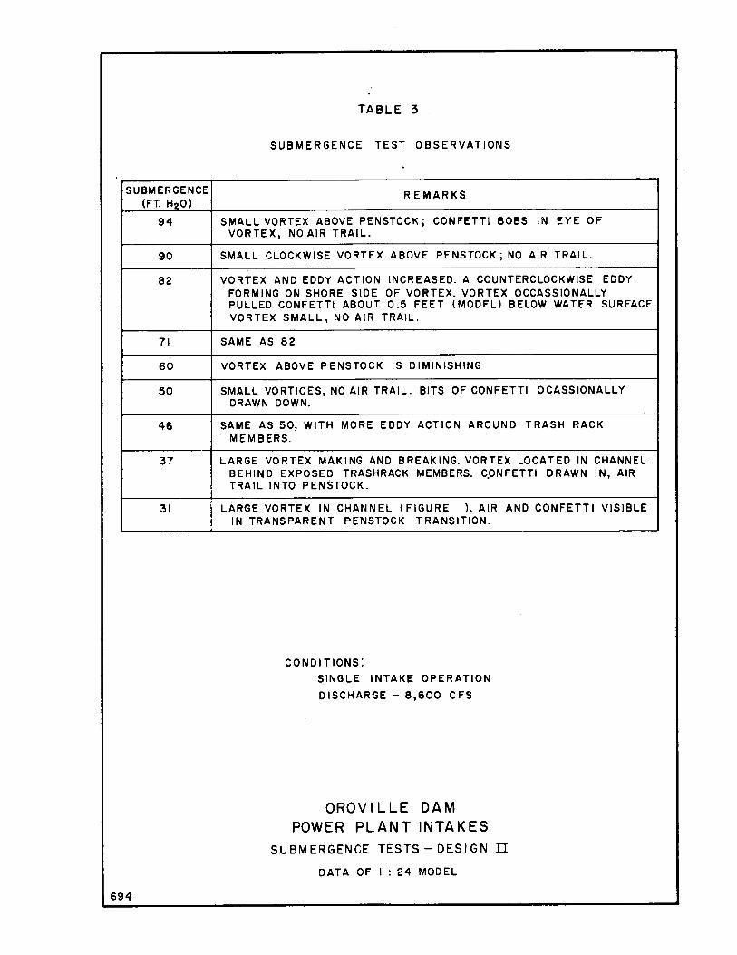
The tests with all shutters removed for single intake operation were made to determine the minimum submergence to pass 8,600 cfs without air being drawn into the penstock by vortices. Tests indicated that the minimum submergence should be about 45 feet. At a 3 7-foot submergence, a large unstable vortex started to form in the intake channel; at a 31-foot submergence, a large stable vortex formed with an air trail extending down into the penstock (Figure 27-A). Observations at other submergences are listed in Table 3.
10

During single intake operation with five shutters in place, shallow vortices without air trails formed when Intake No. 1 was operating at reservoir elevation 7 45 at a discharge of 8, 2 7 0 cfs. A large vortex with an air trail extending under the shutters formed when the reservoir was lowered to elevation 740 with a discharge of 8, 380 cfs (Figure 27-B).
During tests with both intakes operating, flows into each intake were varied with reservoir elevati'On as shown in the discharge curves of Figure 12. Eddy action was strong in Intake No. 1, and a shallow vortex formed in Intake No. 2 at reservoir elevation 750. The eddy and vortex action increased as the reservoir elevation decreased. Large vortices with air trails were prominent in the channels of both intakes when reservoir elevation 740 was reached (Figure 27-C). It is interesting to note that the vortices have formed within the intake channels and that they are somewhat upstream from the leading edge of the shutters.
The upstream or leading edge of a group of five shutters is at about elevation 705 (left abutment). Therefore, the above qualitative tests indicate that when operating at near maximum discharge, 40 feet of submergence is required for single intake operation, and 45 feet of submergence is required when both intakes are operating.
The requirement for 45 feet of submergence to prevent severe vortex action when the reservoir is at elevation 730 necessitates placing the bases of the two intakes on the right abutment at elevation 685.
Differential pressures across shutters. --The relatively thin 40- by 45-foot shutters were designed for a uniform loading of 5 feet of water (a uniform differential pressure of 5 feet between the upper and underside of the shutter). Piezometers were placed on the underside of the shutters along the centerline, and model studies were made to determine the actual pressure differences.
Tests with one, three and four shutters on the intake were made with a discharge of 8, 600 cfs. The maximum differentials were 6. 1, 4. 8 and 4.1 feet of water, respectively (Figures 28-A, 28-B, and 28-C). Tests with five shutters were run at a discharge of 8, 270 cfs (reservoir elevation 745). At this condition, a maximum differential pressure of 3. 8 feet of water occurred at the leading edge of the upstream shutter (Figure 28-D). A secondary, peak differential of 3. 2 feet occurred in the area above the intake gate_. When the test was repeated with the penstock intake gate removed, the maximum differential at the leading edge remained the same but the secondary peak decreased O. 4 foot (Figure 28-D).
11
The pattern of pressure intensity under the shutters is essentially the same as a re-entrant inlet. In a reentrant inlet, separation at the leading edge causes a local reduction of piezometric head. Maximum pressure recovery occurs about two pipe diameters downstream from the leading edge.'!_/
A curve of differential pressure for five shutters, using the values for piezometric head found in a dimensionless curve for a re-entrant inlet, is shown in Figure 28-E. These values compare closely to the experimental values found at the leading edge with five shutters on the intake (Figure 28-D). The pressure intensity under the shutters deviated from that of the ideal re-entrant inlet because the crosssectional area of the channel is constantly changing due to the channel transition and intake gate.
A curved deflector was installed on the underside of the lowest shutter of a five-shutter train to eliminate an area of stagnation at the intersection of the shutters and end block (Figure 29-A). The differential pressures at a discharge of 8, 270 cfs were the same as the differentials without the deflector up to a point about 60 feet upstream from the end block (Figure 29-A). The pressures along the surface of the deflector remained about the same as the stagnation pressure on the end block. However, the differentials near the end of the deflector, at the gate recess, were slightly lower than the pressures without the deflector (Figures 29-A and 29-C). The indicated reduction of head loss was noted in the head loss study.
General pressures. --Tests were made of the pressures on the channel and penstock transition surfaces with zero, one, two, and four shutters in place, a reservoir elevation of 73 0 feet, and a discharge of 8, 600 cfs. A test with five shutters was made at a discharge of 8, 600 cfs but at a higher reservoir elevation, 760 feet, to avoid formation of vortices. No adverse pressures were found in the tests.,. and the lowest pressure was a positive 98. 3 feet of water. This pressure occurred at Piezometer 1. A list of pressures for the above tests is presented in Table 4. Piezometer locations are shown in Figure 30.
Design III
Vortex and general pressure studies were not repeated for Design III. However, additional tests were made to evaluate head loss and differential pressures with the restricted clearances between the bottom of the channel beams and the top of the shutters, and the shape of the leading edge of the shutters.
Channel beams. - -Preliminary tests were made with the old haunched trashrack arches of Design II in place to see if the channel beams shown in Figure 8 (Section B-B) could be used to lessen reentrant losses at the leading edge of the control shutters. Tests were made by attaching an extension to the leading edge of a shutter so that the
12
top of the extension corresponded to the top of the channel beam (Figure 31). The extension reduced head loss by 0. 3 foot at maximum discharge (Figure 31-A). A comparison of differential pressures across six shutters showed that the extension reduced the differentials by about 1. O foot under the upstr:eam shutter and about O. 4 foot under the remaining shutters (Figure 31-B). These preliminary tests were made with no clearance or gap between the shutter and the bottom of the channel beam.
Channel beams were then placed in the model and tests were made with clearances between the shutter and the beam of 0, 5-1/2, and 9 inches. The differential pressures for these clearances, and with the beam removed, are shown in Figure 3 2. It can be seen that as the gap between the shutter and beam increases, the differentials increase sli_ghtly.
The minimum clearance between the shutters and channel beams was set at 5-1/2 inches by the Department of Water Resources. With five shutters in place, the addition of the channel beams reduced the head loss by about 0. 4 foot. The loss coefficient was reduced to O. 33 (Figure 33).
Leading-edge shapes. - -Studies were made of three leading-edge shapes on the upstream shutter to determine if a small degree of streamlining would reduce head loss. Tests were made with a 90° corner, and with 1- and 2-foot-radius curves. The loss was 2.55 feet at maximum discharge for all three shapes (Figure 33).
Differential pressure measurements were made at 8, 600 cfs using the shutters with the 1-foot radius on. the leading edge. Tests were made with one, three, and four shutters in place. The maximum differentials were 4. 8, 3. 8, and 3. 5 feet of water, respectively (Figure 34) .
13
BIBLIOGRAPHY
1. "Hydraulic Model Studies of the Diversion Tunnels for Oroville Dam," Report No. Hyd-502, by W. P. Simmons
2. "Hydraulic Model Studies of the Draft Tube Connections and Surge Characteristics of the Tailrace Tunnels for Oroville Powerplant, 11 Report No. Hyd-507, by W. P. Simmons
3. "Hydraulic Model Studies of the Outlet Works for Oroville Dam, " Report No. Hyd-508, by Donald Colgate
4. "Hydraulic Model Studies of the Spillway for Oroville Dam, " Report No. Hyd-510, byT. J. RhoneandW. F. Arris
5. "Hydraulic Model Studies of Downpull Forces on the Oroville Dam Powerplant Intake Gates, " Report No. Hyd-540, by K. G. Bucher
6. "Hydraulic Model Studies of the Relief Panels for the Oroville Dam Powerplant Intakes, " Report No. Hyd-549, by Donald- Colgate
7. Rouse, H., Elementary Mechanics of Fluids, New York: John Wiley and Sons, Incorporated, 1957
14

694
TABLE I
DIFFERENTIAL PRESSURES ACROSS CONTROL SHUTTERS
DESIGN I
DIFFERENTIAL PRESSURES, FEET OF WATER, PROTOTYPE
TEST I 2 3 4 5 6 7 8 9 NUMBER
I
2
3
(/) 4 a:: LI.I CD
5
~ 6 =>
z 7
a:: LI.I 8 I-LI.I 2_ 9
0 N 10 LI.I -Q. 11
12
13
14
5.3 2.9 2.4 2.2 6.2 15.4- 4.6 9.8-
5.0 5.3
5.3 2.6 1.9 1.4 3.4 4.8 6.0-- 3.8
2.2 2.4 0.2 0.2 5.0 3.6 2.4 5.3-4.3
5.3 2.6 2.4 2.2 5.0 4.6 3.8 4.1
5.3 2.6 1.9 1.9 4.8 3.8 2.6 4.1
2.2 2.6 0.2 0.5 5.3 4.1 2.4 4.1
4.8 2.4 2.2 0.2 6.7 5.0 3.4 5.0
4.8 2.4 2.9 1.2 4.8 3.8 2.2 5.0
2.2 2.2 0.2 0.5 5.3 4.1 2.4 4.8
5.0- 10.8-4.8 2.9 2.6 2.6 - 4.3
15.4 6.5 4.3-
4.8 2.6 2.2 1.9 4.8 5.0 2.2 5.8
2.2 2.4 0.2 0.5 6.7 5.3 3.1 8.4-7.2
4.6 2.2 1.7 1.9 5.5 4.3 2.9 4.3
4.3 2.2 1.9 1.7 5.3 4.3 2.9 4.3
TEST CONDITIONS SHOWN IN FIGURE 23
PIEZOMETER LOCATIONS SHOWN IN FIGURE 16
DIFFERENTIAL PRESSURE = HRESERVOIR - HpaEZOMETER
RES. ELEV. 790, DISCHARGE = 8,600 CFS
OROVILLE DAM POWER PLANT INTAKES
DATA FROM I : 24 MODEL
12.7-9.4
3.8
4.6
3.4
3.6
3.6
2.9
2.6
2.9
13.2
4.1
5.8
2.6
2.6
10
4.8-8.8
2.2
3.4
2.6
3.1
3.1
3.4
3.6
3.6
9.4-5.0
2.6
5.8
2.6
2.6
694
(/)
a::: LL.I ID ~ ::::, z a::: LLJ ~ LLJ ~ 0 N LLJ -a..
TABLE 2 MANOMETER PRESSURES ALONG CHANNEL
AND PENSTOCK TRANSITIONS-DESIGN I FE ET OF WATER, PROTOTYPE
TEST A B C
CONDITIONS
I 9 7.0 96.9 99.4
2 -- --3 100.0 100.1 102 .9
4 104.9 104. 7 106.7
5 106.0 105.8 108.6
6 11 9. 2 119. 3 11 0.1
7 I 19. 8 II 9.4 100.4
8 121 . 0 120.6 122 .6
9 124.7 125. 0 126. 4
10 125.0 125. 8 126. 6
11 128.8 129. 3 134. 8
12 130.5 134.2 133. 6
13 128.4 -- 126 .4
14 126.0 -- 124. 6
15 127.7 -- 129.2
16 I 29. I 130.4 133. 5
17 130 .I 130.9 134. 2
18 132 .9 135. 9 132.0
19 134.3 135. 6 138.9
20 136.4 137.7 136. 6
21 123.2 123. 3 126. 8
22 120.4 120. 5 125 .0
23 -- -- --24 127 .8 127 .9 130. 5
25 133 .6 133. 9 136.2
26 125. 6 126.5 128.7
27 127.6 128. 9 130. 7
28 130.6 132. 2 133.5
29 133 .6 135. I 136. 2
30 123 .3 123. 9 128. 8
31 126.3 12 7. I 129. 2
32 128 .3 128. 9 131 . 0
33 131 .3 131. 4 133.7
34 134 .I 134. I 136.2
K 0.53 0. 37 0. 24
TEST CONDITIONS: RES. ELEV. 730 DISCHARGE - 8,600 CFS A. FLOW THROUGH PORT 2, INITIAL END BLOCK B. FLOW THROUGH PORT 2, VERTICAL END BLOCK C. FLOW THRO UGH PORT I, INITIAL END BLOCK
PIEZOMETER LOCATIONS SHOWN IN FIGURE 24
OROVILLE DAM POWER PLANT INTAKES
DATA FROM I : 24 MODEL
SUBMERGENCE (FT. H20)
94
90
82
71
60
50
46
37
31
694
TABLE 3 ,
SUBMERGENCE TEST OBSERVATIONS
REMARKS
SMALL VORTEX ABOVE PENSTOCK; CONFETTI BOBS IN EYE OF VORTEX, NO AIR TRAIL.
SMALL CLOCKWISE VORTEX ABOVE PENSTOCK; NO AIR TRAIL.
VORTEX AND EDDY ACTION INCREASED. A COUNTERCLOCKWISE EDDY FORMING ON SHORE SIDE OF VORTEX. VORTEX OCCASSIONALLY PULLED CONFETTI ABOUT 0.5 FEET (MODEL) BELOW WATER SURFACE. VORTEX SMALL, NO AIR TRAIL.
SAME AS 82
VORTEX ABOVE PENSTOCK IS DIMINISHING
SM~LL VORTICES, NO AIR TRAIL. BITS OF CONFETTI OCASSIONALLY DRAWN DOWN.
SAME AS 50, WITH MORE EDDY ACTION AROUND TRASH RACK MEMBERS.
LARGE VORTEX MAKING AND BREAKING. VORTEX LOCATED IN CHANNEL BEHIND EXPOSED TRASHRACK MEMBERS. C.ONFETTI DRAWN IN, AIR TRAIL INTO PENSTOCK.
LARGE VORTEX IN CHANNEL ( FIGURE ). AIR IN TRANSPARENT PENSTOCK TRANSITION.
CONDITIONS:
SINGLE INTAKE OPERATION
DISCHARGE - 8,600 CFS
AND CONFETTI VISIBLE
OROVILLE DAM POWER PLANT INTAKES
SUBMERGENCE TESTS - DESIGN II
DATA OF I: 24 MODEL
en 0:: I.LI ID :!: :::)
z 0:: I.LI I-I.LI :!: 0 N I.LI -a..
694
DISCHARGE RES. ELEV.
SHUTTERS
I
2 3 4 5 6 7
8 9 10 II 12 13 14 15 16 17 18 19 20 21 22 23
24 25 26 27 28 29 30 31 32 33 34 35 36 37 38 39 40 41 42 43 44 45 K
TABLE 4 MANOMETER PRESSURES ALONG CHANNEL AND PENSTOCK TRANSITIONS - DESIGN II
FEET OF WATER, PROTOTYPE
8 600 8 600 8,600 8,600 730 730 730 730
0 I 2 4 02. 7 102.2 98.3 99.0 11 .9 111 .4 107.0 08.0 11 .4 106.8 108.0 08.0 I 6. 5 111 .9 II 2. I I 2. 7 07.0 107.4 107.4 07.2 07.5 102.2 105.1 05.3 09.9 104.6 107.5 07.7 I 7. 0 I I. 7 114.6 I 5.1 21 .2 I 6.3 119 .2 19.2 24.1 I 9.5 121 .9 22.0 2 5. 5 22.1 124.0 23.8 24. 7 22.8 124.0 23.5 2 7. 2 24.5 125.5 25.3 2 7. 4 24. 7 125. 7 25.2 26. 7 24.5 125.4 25.2 35. 7 28.2 132.0 29.4 34. 0 31 .I 132.0 31 .4 25. 5 23.5 124.0 24.8 30.1 29.8 129.5 30.3 24.9 29.9 127.0 26.6 2 8. 2 30.1 129.6 28. 7 I 2.5 I 3.2 II 3. 4 12.5 23.2 I 9.3 121. 7 22.5 29. 2 28.9 128.7 28.3 30.2 29.5 128.7 27.8 33.4 30.5 131 .0 30.1 34.2 31.0 131. 7 31.0 35.2 32.3 132.8 32.3 39.0 37.3 138.0 36.8 3 0. 7 33. 3 130.2 30.5 36. 7 36.4 125.9 35.5 2 3.5 I 3.1 117.4 18.9 2 3.8 I 3. 2 II 8 .9 19.5 2 8.5 21. 7 124.8 25.1 3 3.2 28.9 130.8 30.8 36.0 32.3 133.5 33.6 -- -- -- --130. 7 124.7 127. I 127.8 133.5 128.4 130.3 131. I 136.5 132.1 133.5 133.8 126.2 II 7.0 120.6 122.3 129.0 121. 7 124.8 126.3 129. 5 124. 7 127 .3 128.3 133.6 128.9 130.8 131.6 136.0 132.3 133.8 134.3 0.21 0.45 0.37 0.36
PIEZOM ETER LOCATIONS SHOWN IN FIGURE 30
OROVILLE DAM POWER PLANT INTAKES
DATA FROM I: 24 MODEL
8,600 730
5
39.0 38.0 38.0 42.6 37.0 35.3 37.7 45.0 49.0 51 .9 53.5 52.8 55.2 55.4 55.4 58.6 61 .3 54.3 60.0 56.3 58.9 42.5 51. 7 58.5 58.0
I 60.3 I 61 .0 I 62.3 I 66.8 I 60.2 I 65.4
148.9 I 49.2 I 53. 4
I 60.6 163.5
--I 57.6 160.6 I 63.5 I 52.3 I 56.0 I 57.8 161 .3 164.0 0.37

T,18N.
642
T.21N,
I I I I
---~-- --1----~-,/-~,'I"~"""~ I i :
I I
I I
: I ---;----~-I I I I I I
----t----1--1 I I I I I -----1- -- -,---1 I I I I I I I
------ - --1- ---1-1 I I I I I I I ! I I
R.5E.
I -i----1 I I --r----1 I I
--1----1 I
I I - r----' I
I I I
---f---1 I I
---i---1 I I ----~-- -I
I I
----1
FIGURE 1 REPORT HY0-509
R.SE.
---+----·-I : I ' I I I : --+---+----r---:--
' I
EUREKAGl PROJECT AREA
01\0VILLE
SACRAMENTO •
I I I I
--1----f---..l.---~ .... I I R.~E.
I ---,4--
-L-~1~--l---l-~ ____ l__ I I I I ---7-~ I
I I I I I
----:--- -+----~---1----~--- -----i---1 I I
A.5E.
I
I I .----,----
' I
-----i--1
SCALI: r, MILES
SUBMITTED•
h. ,li8 .. CHIEF. OAMiaN s1Ecr10N APPROY£D• DATE: MAR 1 7 1982
APPROVAL RECOMMENDED• :ci&c~ DIVISION ENGINEER
APPROVED• DATE: MAR14'1!18l
CIVIL ENGINEER NO. 12676
OROVILLE DAM
POWER PLANT INTAKE STRUCTURE STUDIES
LOCATION MAP

FIGURE 2 REPORT HYD-509
1 UPPER FEATHER ltESERVOIRS •
2 OROVILLE FACILITll!S
HORTH BAY AQUEDUCT
4 DEL TA PROJECT
5 SOUTH BAY AQUEDUCT
6 SAN LUIS PROJECT C Joint with U.S.)
7 COASTAL AQUEDUCT
8 CAST AIC RESERVOIR
9 CEDAR SPRINGS RESERVOIR
10 PERRIS RESERVOIR
OROVILLE DAM POWER PLANT INTAKES
CALIFORNIA STATE WATER PROJECT
\ (-~ I
'---,so
'~:\ I"-) ~ ~ <::,
> \ "' ~ ~
3 ... r-i-=-°4Ks- 3
/nlolfe 5/ruclure R,9nl Abu/,n,..n/
c,C. :.c- :=;,.=
_, ,,,.~ ~=:roul Goilery . ' cc=""= co="/
FIGURE 3 REPORT HYD-509
01ver.s1on Tunnel /\lb ,J---._ \ \ ·, \
\ \ \ \ \ ' \ \ 01vt1r$1on Tunnel No. 2 ~ \
\\ '\ I I I
1' \ I \I
I I
Tunr>el Plug-~ Rwer Ou/I~ ;w; u 'ck ~ccess Tu;,;.,el ~~
E9uo/1z1ng Tunne/---~\::-r,1
,, ,./ 1
\ \1' ,, Valve Air Supply Tunnel-- -~·i\ \V ,,. -::.:: :=
' ~
: ,.Jf \'-~' Crner9ency Exd Tunnel~ ~~1"~ .... -<: \ -::==-1/
1,
-~;:;.- I I \...__ ( // I I
"'" -, \ I I,::, "f '_ 00.;/ , ~ccns Rood: ,,,~-=--=-a==a--~~=,. ""' Oro/l Tu~ , , ,;.-.-;, , j ~ .......;;."" _ Tunne/5 \~ 1 f,.. --:::~rt?n.slock ~
~1-" \.;:: ~ · · Branch Lines '\S I- I J 1, ~ ( I .
"""::,~
Oro// Tube5 ~"" :.:c ~Powerhouse ~11 nrl -.,.,"'".,,,..."=:::c==~=~
I •
~-Ax,.s o,f Orovtlle Dom \\ I; \I I I . ; l'I' , I
~,fl
//,
Mup', Vo/loge_----+•-...;-,<' ;, '1 1
1
Cob/e Tunne/ / I I I \\ 1
\ /.
Access Tu~/~ \_\'y-_)x Porto/ ,;,,--r ~,
// ·\ 11
!, /!
I I I '
I I
/ I
I:
~ l_
Pow,rhouse Access Tunnel
~ '1 "' '¾::, '--'
i
/ " ~
~ \
, I 'I>
% \
NOTES
0/Jsertl'ohon An,u
I V1stlors
Th/s drow1n9 is For ,nFormoflon only e~c,pl For /t!'/'i obu/ln~nf locat,on ond Conirac/or's worJ, or,a.
C Thi!' confracra,18 worlc,r,g or,o :Jhown i• oppro,1,mol?.. rh, "'°'"""•ncr o, f111a or110 bnd lh4! moin.,.,nancr •f'on occ,ss rood lo fh, worlting orwo will .. :iub.J«f ta d,,,ction by th,, Cng,,,..,.__
200 0 200 400 600 800 ~~ ( I /
r =200· _.
-· .. --·
SC.Ai~ OF FEET
SAFETY - • N--., • WATER . SfAft CW CAIM"OMIIA
TMK ft~ ANNC:Y Of" CAUl'OIINIA DU'AIITMINT ~ WAHR ltUOUIICU
DIVlalON Of" ...._. AND COtaTIIUCT10N
STATE WATEJI FACILITl£S OROVILLE DIVISION
OROVILLE POWER PLANT PENSTOCK INTAKE - LEFT ABUTMENT
SITE PLAN

EL. 922.00
Fig.3
Normal Power Pool EL. 900.00
I I/;
I Sfrucfure I
lj)_ I
I/; Infake No. I In fake No. 2
I
I "'· JNTAKE STRUCTURE - TYPICAL SECTION
I
Boffom, Normal Power Pool £L. 730. 00
Minimum Power Pool £l. 640.00
EL. 613.00
EL. 274.00
El. 252.00
EL.234.00
t I
EL. 215.00
, .... -::~·01;-;: El. 205.00-
~~'~;:~, '\,ffl'v ,;.,, oo·· ___ ·::~~--~~ EL. 16.3. 00 EL. Varies
SECTION THROUGH TRANSFORMER VAULT
~ ~
$quipmenf Building POWER TUNNEL -TYPICAL SECTION
q;_ Intake Structure
GENERAL PROFILE
" ,~«>)," I ': 2>"
: <5'0 I ~O
ti; Palermo Ouflef Works
Iv!",~" I O
0 l, rToe of Embankment
~o 11."i'-t / /' \ GENERAL PLAN
I
1/7c,0'l,i I /, 1/:i 0. I . I / ;.0 ~ I I
/;.._0~ // I I. /'1 : I
t{/&.-1.,JJ> ~ I
/ I
/ 0 '-. ov \
/ :;:_.< ~o· I 1.,_<> ~ . r-"-' <s.,1.,_.f'
0,c,
)
/ I I
/ I
EL. 274.00-
GENERATOR ROOM ---
EL. 252.00
SWITCHGEAR GALLERY -
EL.234.00
TURB!NE~J FLOOR OO EL.2/7.
-(&
EL. 188.00
UNWATERING
GA L L ER Y ------------
I f !
FIGURE 4 IREPORT HYD-509
H. I/. CABLE 'VALLERY
El. 215.00
ACCESS GALLERY
EL. Varies EL. IB?.C~ I ~:f': in1 II EL. /63.00
SECTION THROUGH { UNIT$
~ I
El.252.00
El. 234.00
£l.2!7.00
.£L. J-!8.00
EL.160.00 £L · 125. 00 tL-jl
SECTION THROUGH SERI/IC£ BAY

8L"' ~i ...
"'
--- .so.,t'
TYPIC~ SECTION
lnfok.e • ® !_
~ g .. ~
I I
., I
MQQ'
1c:i
:;;Is:~ '/ ~~ ~
'EL.58?7S c\ ~
•l£L. . .5"!SOO ~-~ ~1~
1"
EL. 535 00
@ Pe~lack~ ,J~~Lro' ,
' rg.00' t
h iti~~ -t = ~ (! ....
Bda,·Holf
--~
~
" ~~ ~ § "' ~ -!1 a Q'),G
STRUCTURE PLAN ::Jcaf• 1··a ;o'
~....r~.,. ~y .. · ,(K .. tl,d ~~ I" r bo'the_o.ds. tyf
';hell st!dlOIU. .s::
NOTl!:S
~1 "' 0 "'-, '> ~ :id 'Ii 0
~
,;;
~
"'
f. Elrzvofians g,v,zn arrz to finish1Zd focq. ofconcr•fg flxce:pt as ofhe.rwis« ~hown.
2 Cf1Zvafions shown of .Sfofion.s and al eKponsi'on joints in Secfion A-A Qr& fak.en of the tnv~rf of fha. ChQnna.l s«cfi"on.
J. The symbol Ll rrzfers fo fhq, ,t location of Shuffcr Gofa T"z Down Block.out - s,ut Sh 20 I 1./ for d(l fotls.
720_7~5::,:~,}3 for Y ~
5eCT/0N 8-B 5ca/e 1• ;?O'
- G,CNE:RAL NO Tt:S -
For o list of a/Jbr.~riofions ond symbols usttd in this set of d~Wingl .u,: Sheet- 2a
2 Un,f Oe:t1/9n Slr~5:,e~ Remforced Concrele
t;• 70,000Mi r1• JO
~ - 1350 p~i Slr-ucfurof Sl-e~I
/;,c 2-QOO:Jrs: Foundaf1c-1; Pre~:111rti'
5ound Rock 50 T51" FraclL-red l<bck /0 r9F'
3.Cllaml~r or t'/111!6/~ 815 .appropn'.atd-, all
e)(,p~s~ corner.s ~.,.-nch.
IIILVIEWEl>-BTAFF
ENGINEERING, BIi.
8.E.JiH.R.
1··- 10:0·
1 • 20~0·
FIGURE5 REPORT HYD-509
filM?.:. 97.~1'
B
_J
O /0 ;o .$0 40 50
o m ro • e ~ = "5CALE OF FEET
SAFETY-•• N•cesw, os WATER STATE OF CALIFORNIA
THE RESOURCES AGENCY OF CALIFORNIA
DEPARTMENT OF WATER RESOURCES OF DESIGN AND CONSTRUCTION DIVISION
STATE WATER FACILITIES
OROVILLE DIVISION
OROVILLE POWER PLANT
PEN STOCK INTAKE - LEFT ABUTMENT
STRUCTURE LAYOUT
FEB-51963

D tJ'o DO 0
1-·
:5!:C i'/0,V l'J-,4 :sc11,:.c: !,;,''~ 1:.0"
.II' .,.. :....:......
D D D 1,
0 D,D I
D DiD
..
~-
<5Xf,;' e;Rrl!'~ -'
(.OA/GI TOOIA/11!. '5EC T/ON :Ff/OWIA/<J Sf/{JT,~eRS /Al FULL Ol'l:AI P05I tto,V
~c,u .. ~: r·:: so"
,U:5rr_VOI,<' W. :5.2__
LONG/ TUl)/N;:/l 5cc TION :JC/ICE: i"•ZO'
;,01:1 T f'OI! SHUTT£.C:,C._ /"·
~,,,''
~
Ol"i!#.'l,/6 -Sfft/rrl~
FIGURE 6 REPORT HYD-509
TYPIC~C. 5Ht/TTER
[il
' ~ :51(/1/ l"Ll'/TE
? ..-nlP,"OJ!i ISOl?:>_
Pt.Ill.I
l::5(1,•PO~f' 40<r-z_. -a,. ~ < 5,-,1N&-~ ___ ~
-- I __s--:::.,ft?ih ':1,';/A/ l"UITI!
ScCTIOAI
==,
iJ O~T,4/~ Or SHUTTE~ r~.4M!Nt; IIAl!J 5K/A/ ' Pl~ TE COIJ,VcCTIOA/
:JC/1,_E ~- • l'O"
5C/llz!: /'' • 10'
STATE OF .CALIFORNIA DEPARTMENT OF WATER RESOURCES
OROVILLE DAM
POWER PLANT INTAKES SUGGESTED SHUTTER DESIGN
LEEDS, HILL AND JEWUT, INC. CONSULTINII UNIINEERS
......... ott••• CNEGICl:D
AHWIOYCO
r1nr
----8
.... • i .. ... ...
; ~
~ :-; "'
I----_ 35. 00' -~~ (!O'
:, : !l ~ ...
+---
Trc,ahr-ocl< Support STr. [Z]
~ -~- Shutter
@
22 oo'
VIEW C-C • 5cc,,. 1'•'10'
( ML,Y pEV£L.OPED C>IANNEL T~N~/TION TYPICAL CHANNEL .5£CT/ON 0
\
I .... ~
!I~ ----A-4S37-1
''---- 1 nt•II• ~ate {!]
SECTION 8-B A-4K5- 4
5ca1• , .. ,o·
TrosN"cn:11. Support Sfr
~ 'I
Got• Operator [!]
//
/ o-0~~/
~· .JY
1bpoS5h .. p~ ,,,,,,./ t" \
vt:t..r ,w,I >:Q A~ fi),.
,/' \ \ '
~
/-A\
@---·/ ~ ,,,~
~
rap d mlok, c;,.w f ap,roW /ell [§]
SCCrlON A ·A A·4K5 ·4 Sea,., r 0 20
:;:;~-
FIGURE 8 REPORT HYD-509
I (l] Oporof,n9 DocK Sfrucfuro
- .Snutte-1- Go,..tr, Cron,@
""' 0
E•••t.inq Chcu,f'l•I Ccwer
T ra.hraclf. ~ -
'
tl,i6l'IT
~ '1
vo.sko TT~ !L
', \ntak• 6,oh# Op.,--alor Slop
~
NOTES
I For de1b,,,. of rra."lhrac:I< SupporT STruc:Ture •- .t,..g A-4$$1·/~ 2. FOr detai/8 of Trc,NJr~lf Se• ari,g. A ·45~7-14 .J. For aero,la ef Operaf,ng OecK SfrucTure s~e O'wg. A ·4S,7-a 4. For dvTol/& of ShuTTer see dw9. k4SJJ · If
..1: For Jocc,T/o"~ of bioc:l<oU,. i,n dtonnl'!/ tr-,,u,T1on •e• d.,,,,.. ,f-4,SJT-7 6 For oeTads 0, .Infal<e Gar. .see dw,!J. A·4Ll!!,·J 7 For deta14 or ]t,folf• ~o1r OperoTor see dwg A·4L.l!J•I e For QefCNIII of I1'1oKr Gate anc:t Oper<:1/or Roil a~e ttwg.,.A·#-LI•·• 1~7-6 8 ror c1er"** aF Shu1Ter Reul ~ee d,,,,g. A- 4$,j7-6 /0 /:'or C7e1o0k oF ShuTter (;o1'Try Cr-ane -e dvrg A·4L l~-15 II For def-13 of I1,fc,K• f;ote Gont.ry J-1.11I .-- dwf. A·4.Ll6·/0.
~
,o t"'•IQ'
0 ,o 44 ~ M)
,·.,a· /0 l
0 .... /0 l
'-,.0 !JC.ALE OF FE.~T
.JO l "f
SAFETY - -~- WATER STA.ft OP~
TNS IIUOWICD MIDCY 0, CM.JPOIINIA DU'AIITMDIT Of' WATSII __ Dr-/WION 0, ...... Alm ~
STAT[ WAT(II l'ACILITl[S OROVILLE DIVISION
OROVILLE POWER PLANT PENSTOCK INTAKE- LEFT ABUTMENT
STRUCTURE LAYOUT - Mftl .Jl'L J I '"'

End Block Fae& of'~
"'
D .
.A rii.,-B
. ,, I
cr,k -µ'M_ -
------------ -
• !-:·- I ::i; I 'D1J
: " I \,, °' ~{ I <f. Jn"take Q)
-~ :;:
.
.'P ~
--Lin~~
.-±-: -- --~-::::CCC''-''~-''--~-:- ----==•-·=c••~"C~=-~
I ~c ----------
A
-_;~_=·-::::-=- ~~=-Line b t
, .. I :~ I A -~\y- _ H----'-1...a.;-+------- _._ _ _. ___ ,___ ~'r-t~-+--- lnra~k~.,~ln::ov<'=r..:t-==--=-~---------
0\ <:i I t9 -
~ ~ I Air V•n+ r--F==-=b,cl=~T,i,=n~o,~;::!,;,:'.;,,~----------t------+----------------------------------....6i!a12!_2::,~!it:£2..=::::iL=-----1 ~it;
;:_
---,f-----'---ll------------------+-1'--~---4-------- 84'-o..,
I _____ _____ 74'-o"
I l I , .
\, _, ~
~ 11;
FIGURE 9 REPORT HYD-509
~
~··~ -L- • ----------------- - :t -- -~ - ---~~:=~ --~~~-~~=~§~~------~~:__ dd - -------=_J -~-===-----:::::::==::-...::=--~
~
l
I -
. 1------------------------------------------,.------~-------------------------------f
~ .:: ~, IA\ rw
4-7<15"
i "' ~ !It i~ ! ij' it~ ij' i
' ~ - . CJ (
l "' " ~
I '(
i: ~-
~ ·._ - .I I ' 'J -~ ________ :- __ , ~ ,'--!fin,cri e .1"-Y • 1ro·-~r · ~--------~-------~.-J..l'-V
~:~ f-1.,,&N CDw ,Sc~..,,,.;,,~ \E)
Ctffilpriil 77--,,h.~ion - IK!~O"
@-c
L'"• • u;..."·;,·
,., t -~·~
9':J~ 9 } ·,. ~ Line b
• • • • • • .,.. • • • ' • ,, " '> ~ -'------''--_,_ ___ . ip l-·,· .;. "' or ~ • 11 • •' ··"" .., q 1 'Line"b
'~ SECTION A-A · -Sc.eto, 4,1·
92 Jn~aife L1nfl •
Q;: lnToke
[ ', . ,
Consf Jt,
L...1ne b
Line of Cenrer..s
Lin•
~~ 8~9~ Q
------------- Con.st', Jf
b
~T-· L Jt
~LL----=-1'--"--.,.-r.-+4<"-..:::..---4-"--''-..J Const .;t. ---- --- L
14
_
4
, , .' , lnrA___JX9 lnV@r+ I
----- z~':::_!;i" ---
-6cCTION B-B X~Je-: ;?'""-;'
!IS -ts 1~8"
• loo,-~----1-----~ 1:0" 15:..94· J\IOl/!!=l.;':u/:::::;.9,Sh..,_2, t,nd 24 _ ·~--- l. For Tn,pezoidvl Info~ C'honne/
Line of" Re,n Force.m1nt. Sett 5·heef' /9 , T Cen'te-r.s 3. For Key IJf!.foi/ ond Rtt/nioramrnt, I l s,~ fhae-f I !1.
I ~
! 12 °6· s...,, Sh~I <'2
L , ... , IO I s 10 .a 2S
SCALE OF FtEtET
SAFETY-as N•m-, •• WATER STA.Tl: 0" CALIPOIINIA
"I \ /y·n~~~lE-r=:"'---'--;~:r:-',-1...b,):!Pmi,~~4
THE MeOURCES AGENCY OF CALIFORNIA DEPARTMENT OF WATER RESOURCES
DIVISION OF DESIGN AND CONSTRUCTION
STATE WATER FACILITIES
OROVILLE DIVISION OROVILLE POWER PLANT
PENSTOCK INTAKE - LE FT ABUTMENT ;;_ L----_,L-- µc::.,;,'-".==.=.=-"-J )(e_y<P,;IO~O.C • CHANNEL TRANSITION
- ----~ s~ Shea+- IS' /iv /on,!-/an.s. - r.-.Yl--.,..-,,__---,_~~_::-_,;--_::-_T;--_::-_::-_::-_-_::-_::-_::-_::-_::-_::-_::-_::-_::-_::-_::-_::-.::-Jc.::-J.::-.::-j.'.'.':ua--M,--TTIC,,,-D,------,-• ....,-.. -.-, --•• -,..,-F-[B---5 195-3-1
SECTION c- C ENOINHIIING, .... ot5ill-TYPICAl TIPA?EZcJI/JAL /NT4k'E •-ov•L••COIJU"-"'11""' _ j
cHAN.-YEL c::,;:t,.ss s&: r10,,v =+-----===~-----1-~---4~~ '-rJ~~AI L' ~- - . IL -Seal•: i''• /' ~:I-~
fi~ C'"-TI! ~"" • l)U
lhV •. ' g,,l,ff I CIMWN I C:tffc:Kl!CI
DhlOl'laD ~:",...,_. I - t'..lU,5__ I T Sroi-tb I~ .._ ,6' , 72,'tL AJl'f'ROYAI_./, ·alj. 0 A::·rs 3 2 - s 11"tr· -- --
~-e~
~ltt:t..:._
~~
I
J ' \ J ~ 0 .. ~ I C\j I
Controcflon Joinfs .s,,,ac•d ,?•'-~" c.c.
rs
• •' <
~I\/ \ ~, :'' ') • <
.~ sic s "' • • .. l
_ l
~ Cmbed f"our ~,- .ID by /'· tr golv . .st•el pipe af £J•v .$75 00, cen1er•d each 51Qe
;I ~,, /~ ' < • ' - ~
~ • ' II_ ; ~ ij \•• ,..,..,,-\.., / n" ~ L ..,, ,_,?J, ; ... ' 51
,22'·0· f:)1q
.. ~
i
" .. i>
ii ~ £ nd Pen~ tock
/ Tron.$dion
L.Ei•v. .5~.5.0_Q
PENSTOCt<; { CHANNEL i"RANSITIOt:f.
..Seo!~:,·. 1'
~ Po,'11' or 0/ ~ f""9"ncy
1.1'3J' ' -EJer.61444 12' gJ<!. 7.,f l. I
,~-1.2'-.Ji" I 11'11· 11'81' 11'.st'
ll'Ji'
1- ~:,,;1: y ~~~of: p
"---'-=n.L
We4tphole•
. :::1
'<)j ti
, ~I<:> Ii ('4
~I ~
I
,0
I ._t
~-
I
·, ·-
..,·.,,\ C
~\.,, ._-v\ I ; 0 I '-l- ' ·1, ,,
[ y·/1>·.'· ,\s 1. •
m~-~. '~ "'~.:1-p· .>'/'./)~. ~ • ' ' - , ---- A / I , '<) •.• - .. , ~· •. , ! . _P -,'-'-;"'" ---;_/ .A ..
~-"·1,,-~·-·,1/i ~_:__://
o"/?od, 7y,-.1
ENTRANCE DETAIL-A
TRAN.SIT/ON CURVE 5·-e: D 22'- o• 5·-~·
E(i>. __.t:_ ;(0.SSD/
r• (01+550)' ~ I, D,a. 22'-o'
V .
.3.!S'--1~
-SECTION A-A
t ..5col~ Ji~• I'
W-e,-hole•
tJ'· 9'
' .• '-11 ,'. . : ·,4·.
FIGURE 10 REPORT HYD-509
End c:lo•ur• o,nll''-d 1',r c:l.rl'hj. /ior dc+olla IH .,,._,- 62f.
,. 3'-0·
... ~
b ·.:. ..
z::;~~ S'-eJ-K I r~~cc.---~-·-Stoml•s, 5"".I £ro1,51on 1'
~·4·'.
22·-o· __ ~_J HALF - SECTION B-B
Sc111~ ,t.• a I'
:! ..
I _ JI::: 1 I - ' 1 -:cl · I fl•< 575 Jo . . I - ; t::_ I . · / :-I j l8~91ntrarisit,or,\·ti·/\I I
I t t NOTES
• \ ~/ J I • 1 '::::,,~: / Oe,elop~ntA I - I I I -f k I ·, / \ ·.t,,/ £1'" 570.00 \ p ,,--1, 1 ,., __ , ' ' >
\ · • ~ c\ I I '1 /:::,,,-JII ' µ / Dmlop~nt B r v 1 " • . , Ek, ., 65 oo
\ ,e . llpC::' I- 6c 6J' _j , , ·( E.lev 56000 , : f-(~r' ,JI DmlOpment C
'r
De,.,eloµment 0 EIQv. .5.5.S 00
\. • o/~~l,/ £/ev.55000 i\ ~ /~ P / Dm1,,~ont £
.•
J;L.:'-~ ' '··.:/ //'
--.SECTION D·O
De vefoprr ent F Elev. 5-IS. 00
£t:':v5°/o~~n~ ~
Developm•nt II Elev. 535.00
PEN.5TOCI< TRAN.5/TION DEV£ L OPMENT
Seal~ )t'•I' --
t
1 ;; t • ' I-,
Cl 'o ..
P. CABANA
I 2. 3.
... s.
'I
?I "-Cl ,.
b ~ @,
., ~ \J • Cl. ")
'()
S~ sl!ee7a (S/~ • 6NS ror channel Tran4ITlon development . See ,5l!eef• e,m I 617 ;or ch!7f"lne/ 1ran~/1io,, rcinf'or-cerne"T deToi/a. ,9ee sheet tk>8 for pe,,.TocK Tr:inal1/ett _,,d EIWI &lo~IC rein/'orc•'"enr cleTollc. C.onrrol point ro,- loca1,ng Wflopltole• In chonne/ _,,.. CenT•r weepho/• on b•gin,,,g of chann•I t,-a,...,t,on. Fir•1 wee,pho/• "' mv•r1 ~lab l~•T•d 4 :.o- on •ot:h •id• of f; Zn1'aK•i .s•• .sh••T 1$/1. iypicol ,to· modul~. Loca'I~ blockouts and onchor bolf·• for Troshroc,t ~upporf •fru~l-ure os s"o,u" on sheet- 611.
s 0 s ,\'· 1'
10 l.!S :u,
... ,. 10 20
OF FEET
SAFETY - • N-ay • WATER IITM'a OP CAUf'OIINIA
THIE ...::MJIICD AGmtCY OP' CAUl"OIINtA Dll!PAJITMIENT CW WATIER IIDOUIIICU
DIVISION OP' msaart AND ~
56Ab\1tf P iii)liT8 OROVILLE POWER PLANT
.30
PENSTOCK INTAKE-LEFT ABUTMENT CHANNEL STRUCTURE PENSTOCK TRANSITION - OATS: .NII!, 9M
~~/
... ~ "' t ct I
Golf, carr,0911. Se<> Dw,y A-4Ll5·· J --.
/nfake 9ote S~e Owg A-4L/5-2
VIEW A-A
6~
Gale operofor See Dw9 A-4L 15- 4
ELEVATION INTAKE GATE AND GArE OPENATOR
SHOWN IN NORMAL POSITION
/\
\
air v•nf
'()
...
FIGURE 11 REPORT HYD-509
' - ~ ---j I 21'-o· ... -c
lnlok• 901• roll•r lracJr, ~~'- () __ ._(! -
lnfalr, 901, $/of
SECTION B-B
121 ~i,~~~ ~ ~~ ~ ~t ~ - -1~ ..,
gale
. = I 113'-0"c-c lntolte
~arr,oqe (' gale o.c,erator ,-.c,i'/.:.
_,?__$__:__- O_~ __ Q_-:_Q
Gal" opera/or slol
SECTION C-C
NOTES
I. - F"or conlro/Jin9 d,monsion,.3 of" e~,p~r,f see de/ail drawmg.s.
2 Tha drowln9 1s Typical For two 1nfo,te, 90/es or,c/ 9ater op~al-or-.s .
_1'. 0 , .... ••• ,. L.0..J..JU...L..---'----'---..1..-~
SOALI 0,- f"CCT
5AFETY - -~ • WATEI
fttS ..w:~~ DaPMTIHNT OP' WATml -
DIYalON 0, ~ AND CONnMICl'ION ST&TI W&T[ft ,aclLITf[S
OIIOYILLE OIVISION OROVILLE POWER PLANT
PENSTOCK INTAKE - LEFT ABUTMENT
INTAKE GATE AND GATE OPERATOR PLAN, ELEVATION AND SECTIONS
.. ,.AUS.,1914

i--: IL. I
2 0 I-
~ w _J w w (.')
~ a:: => Cl)
a:: w I-~ 3
694
900
860
820
780
740
700
660
620 0
I I MAXIMUM HEAD--- --,
INTAKE NO. 2- ----
\ \ \ ~~ \
FIGURE 12 REPORT HY0-509
\ ,\
\ ,---INTAKE NO. I
IN TAKE NO. I ' \ 2 TURBINES, I PUMP-TURBINE
INTAKE NO. 2 \\ I TURBINE, 2 PUMP- TURBINES -\ \
CRITICAL HEAD 1----· --1 ) I I I I
I I MINIMUM HEAD--- ---- ---- I I
I I 2 4 6 8 10
DISCHARGE - CFS x 1000
OROVILLE DAM POWER PLANT INTAKES DISCHARGE RATING CURVE
_o-
•••
I-<--
' ' ~-----[
I
' ' I I I I I
: ' I I I I
: A i A . . ,
_9 <D
' I I
' ' ' ' ' I i
~-,_-I ' I I I I
' ' I I ' ' I I I I I •I I ..-, I _,
I en I I ' I I I I I
•1 I ..-, I
' I <D ' _L
o· _"O
8-:,.-
·>--8
-21 '._ 3"
I
' ' ' ' ' ' ~,.. '
-------->-! I
:
"Rock Baffle
J ,--Water Supply
A
~~:>--Discharge Control Valves
-..,. ')' :
___i___ Q ___ s"r Dia. Orifice
PLAN
Ground Line,, ' I
I
·.6 ·o ·o
SECTION A-A
---Pio stic Transition
0. o·. ·o ·=
,--6 Rock Baffle
---
,,-Labor9tory Floor
·o ·=· =
'.'O
Plastic Transition----•
.-o.· ·.,;- .b_0
. ¢? .. Q· .o_._o
,,-Discharge Control Vol ves ,, /1
,' \ s"r Dia. Orifice------ /Deflector ·'\ b_ru ,0 o>:,:o:>:a:_o .. :6; .0 :a·._:.c:,·-)-~:_-6_ .·.o-·-._o. 0 l{L --- --
/ Laboratory Floor-------
SECTION 8-8
NOTES
/
Walkway and stairway details not shown. Construction details omitted. All dimensions - feet and inches model.
OROVILLE POWER PLANT
0, o·.
0 O·
0,
DAM INTAKES
MODEL LAYOUT
I : 24 SCALE MOD EL
Laboratory Sump
FIGURE 13 REPORT HY0-509
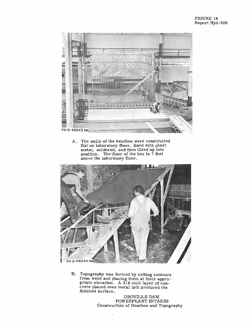
A . The walls of the headbox were constructed flat on laboratory floor, lined with sheet metal, soldered, and then tilted up into position. The'floor of the box is 7 feet above the laboratory floor.
B. Topography was formed by cutting contours from wood and placing them at their appropriate elevation. A 3 / 4-inch layer of concrete placed over metal lath produced the finished surface.
OROVILLE DAM POWERPLANTINTAKES
Construction of Headbox and Topography
FIGURE 14 Report Hyd-509
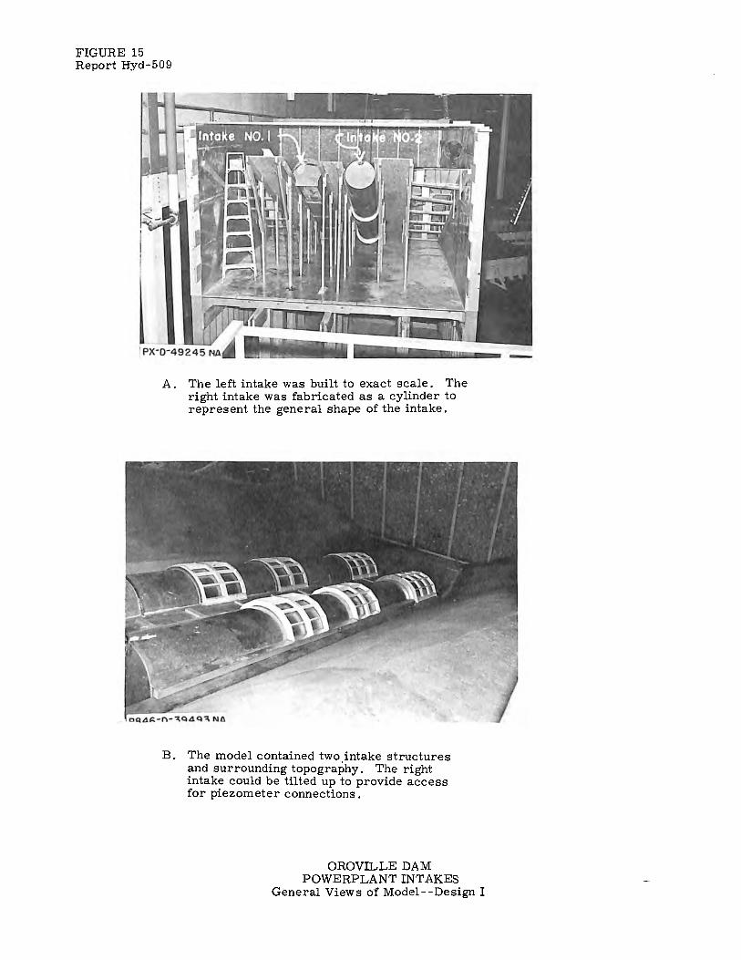
FIGURE 15 Report Hyd-509
A . The left intake was built to exact scale. The right intake was fabricated as a cylinder to represent the general shape of the intake.
B. The model contained two intake structures and surrounding topography. The right intake could be tilted up to provide access for piezometer connections.
OROVILLE DAM POWERPLANTINTAKES
General Views of Model--Design I
694
FIGURE 16 REPORT HYD-5O9
A. CONTROL SHUTTERS WERE FABRICATED BY FASTENING ROLLED SKINPLATES TO MACHINED END RINGS. FOURTEEN
PIEZOMETERS WERE PLACED IN THE RIGHT SHUTTER.
I
i
19
,/ , , ,,
~/ ,,,,,, \i°N2.....--q,"'/~10\:. q·, ,,,,,,
, , I
./ _____.....-- 22° ?--- _L
FRONT VIEW
B. PIEZOMETER LOCATIONS
OROVILLE DAM
9
B-ff------------------ffl3 7 14
•12
II I" ->l'<--- (TYPICAL) ,, 16
I I
: 1011 I K ----------------------->' I I
ELEVATION
POWER PLANT INTAKES SEMICYLINDRICAL SHUTTERS-DESIGN I
I : 24 SCALE MODEL

FIGURE 17 Report Hyd-509
A. Haunched trashrack arches were fabricated from No. 18-gage sheet metal. St:r:uts between the arches were machined from aluminum bar stock.
B. General view of intakes. Eight shutters are in place under trashrack arches of Intake No. 1.
OROVILLE DAM POWERPLANTINTAKE
General Views of Trashrack Section and Intake Model--Design II
1 : 24 Scale Model

694
--r I
·o I
·oi C\I
=o I
·oi
: -:-'-!
-1--:
·o I
·o C\I
I I
FIGURE 18 REPORT HYD-509
I I II ·I r<-- - - - - - - - - - - - - - - -40-0 - - - - - - - - -- - -- - - - -~ I I
SHUTTER--~
--------i--1 I I
I I
I
1-- l=l ·oz _I <!> oC\I !/)
LJJ 0 1-1
I I
en LJJ :,,:
~ z
~
AREAn = 1010 SQ. FT. AREAm = 1136 SQ. FT.
11'-o" - - -(DESIGN lit)- - -
CROSS-SECTION OF INTAKE CHANNEL
SHUTTER-
,,~ --:::-...-+-,i-_0...: ~~{ I
'-- - -~o€.s\G
-~-- - - -DESIGN m
I I
en LJJ :,,:
~ z
~
FILLET REMOVED IN DESIGN m------------
I
---s'-9"--->-l I I I
-,;:s
_i ___ - - I '-'i ~~ I '·c:1·' EY~J,~w/21W· - ->-l2- ;<- -
CROSS-SECTION THROUGH FULLY DEVELOPED TRANSITION
OROVILLE DAM POWER PLANT INTAKES
COMPARISON OF CROSS-SECTIONS OF DESIGN II AND III
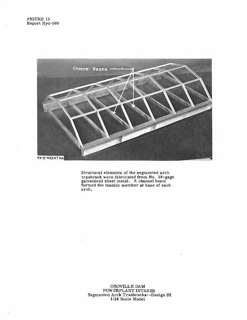
FIGURE 19 Report Hyd-509
Structural elements of the segmented arch trashrack were fabricated from No. 18-gage galvanized sheet metal. A channel beam formed the tension member at base of each arch.
OROVILLE DAM POWERPLANTINTAKES
Segmented Arch Trashracks--Design III 1: 24 Scale Model

Cl)
.0 ::, +... Cl) +Cl)
E 0 C C ~
694
Reservoir Elevation
FIGURE 20 REPORT HYD-509
_=1~~=----=-=-==_=-_-====-~-=====~-: -I I
:;
i J
Q. :::c: --> Cl)
w u ·;: +Cl)
E 0 N Cl)
a.
H = Losses + Velocity head or
Res. Elev.-Hp.
.. ·.· ·, ...
. o_-. ·.· . . . :o ::1 1··: •/
·:o . .. .. ~. , ..
10.:·.
>.. .¥ C
:of gJ +-·UI UI
, .. P1
cc Cl) C a. ... +.
r-f-Elev.535 : .ll: ,. u C 0 ·- +-0 U1 - C Elev. 513--,, I Cl)
ra r;; j__ a. ', V
----- Ring of 4 piezometers in model.
OROVILLE DAM POWER PLANT INTAKES
ELEVATION OF INTAKE STRUCTURE AND
DEFINITION OF HEAD LOSS MEASUREMENT
694
0
5.o------------,----.------r----r-,-,,-m
4.o I I I I I I I I A I J
3·0 I DESIGN I - SINGLE INTAKE
1
OPERA~ION I I I / I fl I A. PORT 2 OPEN, INITIAL END BLOCK.
8. PORT 2 OPEN, VERTICAL DEFLECTOR.
C. PORT 2 OPEN, CURVED DEFLECTOR.
D. 2 SHUTTERS OF PORT I OPEN,
2.01 IN ITIAf END BLOC\ I I y w I i.A I
1.0
V = AVERAGE VELOCITY (Q/A)
IN 221 q> PENSTOCK
w (!)
~ 0.9
0:: <:1 I (.) Cf)
i--: LL
I (/) (/)
0 ...J
0.8
0.7
0.6
a
~ :J ~
X <:1 ~
0 <[ 0.5 w I
0.4
0.31 I / /I I
0.2 I ;< I II
0.1'---------.....,,_ _ __._, ______ ---L... __ ___._ __ .......__....,__ _ _,____.____,._____.
I 2 3 4 5 6 7 8 9 10
DISCHARGE - CFS x 1,000
HE AD LOSS VS DISCHARGE DATA FROM 1:24 MODEL
' ',_Intake Gate
~\ \ .,, \ __ .,,. /
/
.,,
' '---- - - -1 nta ke Gate
FIGURE 21 REPORT HYD-509
C. CURVED DEFLECTOR HL= 0.36 V 2 /2g
8. VERTICAL DE FL ECTOR HL = o.37 v 2 /2-g
Port 2 (2 Shutters) open ______ _ for Test A, B and C Closed - - --for Test D
Port I - - --( 3 Shutters) ..... ...._
End Block--, ' '
~ l+-3: C 0 C a... a:::
r
-.z--::;.---~ ~-==-=--=---~-=---=-- D.
------- Intake Gate
-----A. INITIAL END BLOCK HL= 0.53 V 2 /2g
2 SHUTTERS OPEN, INITIAL END BLOCK HL= 0.24 V 2 /2g
OROVILLE DAM POWER PLANT INTAKES
HEAD LOSS TESTS-DESIGN I
I : 24 SCALE MODEL
A. RESERVOIR ELEVATION 710 LARGE CLOCKWISE VORTEX FORMED OVER INTAKE NO.I WHILE
COUNTERCLOCKWISE VORTEX FORMED OVER INTAKE N0.2
( '/2 SECOND TIME EXPOSURE)
B. RESERVOIR ELEVATION 700
FIGURE 22 REPORT HY D - 5 09
LARGE VORTICIES, CLOCKWISE IN INTAKE NO. I, COUNTERCLOCKWISE IN INTAKE N0.2, FORMED IN THE INTAKE CHANNELS.
( 1/2 SECOND TIME EXPOSURE)
AIR TRAIL-----
/-RES. ELEV. 700 I I
SHUTTER
C. LOCATION OF VORTEX IN INTAKE CHANNELS SIMULTANEOUS OPERATION - 8,600 CFS INTAKE NQ 11
7,900 CFS INTAKE N0.2.
OROVILLE DAM POWER PLANT INTAKES VORTEX STUDY - DESIGN I
I : 24 SCALE MODEL

0,
'° _,.
PORT 3-----
PORT 2---
SECTION ALONG ~
INTAKE NO. I
I. PORT I CLOSE / 2. PIEZOMETERS ~ IN THESE TESTS. ,_-MIO-POINT
SUTTER OF Po::oWNSTREAM : 2 ' '-».
NOTES
PORT 2
IN LINE------..:._
TEST 4 - PORT 3 OPEN
TRASH RACKS IN PLACE
/MID-POI/
f~~ TESTS 5 AND 6 - PORT 3 CLOSED TEST 7- PORT 3 OPEN
\
PORT2 /\
TEST I - PORT 3 CLOSED
""'' ~\
~H RACKS TEST 2 - PORT 3 OPEN IN PLACE
/' TRASH RACKS ""1/ ""'' ~~· / TEST 3- F.'ORT
/ TRASH RA 3 OPEN CKS REMOVED
RACKS IN PLACE
OROVILLE DAM POWER PLANT INTAKES
CONDITIONS AND SHUTTER POSITIONS FOR VIBRATION STUDY·
TEST 8- PORT 3 CLOSED
TEST 9- PORT 3 OPEN
TESTIO-PORT 3 CLOSED UPPER SHUTTER OF PORT 2 OPEN
::u IT1 -0 "Tl
l~ci, -f C
:ti, ::c ITI -< 'i' I\) u,Ci,I
0 co

Elev.
·.c,
194
//
·o
/ 1~.; /
)1)-\,..,.~ ·o
· .l<i.Penstock-,,_
Q.
·o ' :-2.J'¾ ) / f3,
~,, /x
2 ~ ·---: ...
--A 3 '
"' "'-' j__
·o
. Cl. o.
SECTION C-C
ELEVATION
0
;, 0
PIEZOMETER ~LEVATION
I 630.0
2 629.0
3 626.8
4 621. 7
5 620.8
6 607. 6
7 605.8
8 602.0
9 596 8
10 596.0
II 591.3
12 588.4
13 598.6
14 597 .2
15 592.6
16 590.7
17 590.2
18 584.5
19 585.5
20 582.0
21 599.0
22 597. 5
23 592.8
24 587.8
25 585.3
26 592.8
27 590.8
28 587. 8
29 585.3
30 597.5
31 592.8
32 590.8
33 587. 8
34 585.3
PIEZOMETER ELEVATIONS
r3o'-~J. I / ·O 1
,'6 X - ,;'' ':r
'Z --;-
-¥
0
·o
0
0. /\--
8 '
O·
0
0
0
·o.
·. o_
0 .o
... "'-' ___ L
9
12 31
32
33
34
~----<i. Intake
21
t22 +26 L3
+. 27 G}
i '·--Air Vent
28 24
' t29 25 -~ 3.o' 1--
SECTION B-B
<i. Intake------'
~ u ·o
j" 14 r:~ 0
i, 5 0
16~. G
0
19
17
i 18
0
a
.0
10 - :~ -·t- -- 20°R
20
·O 0
0 0
SECTION A-A
OROVILLE POWER PLANT
DAM INTAKES
0
PIEZOMETER LOCATIONS -DESIGN
I: 24 SCALE MODEL
I
FIGURE 24 REPORT HVD-509

694
...... :iiC
I-z w -0 LL LL w 0 0
(/) (/)
0 _J
Cl <( w I
0.5
0.4
0.3
0.2
0.1
0 0
NUMBER OF K SHUTTERS 0 0.21
I 0.45
2 0.37
3 0.35.
4 0.36
5 0.37
6 0.39
DISCHARGE
8,600
8,600
8,600
8,600
8,600
8,600
8,600
FIGURE 25 REPORT HYD-509
HL
1.66
3.57
2.93
.2.77
2.85
3.93
3.09
A-HEAD LOSS - 0 TO 6 SHUTTERS.
,,,,.
\ ,· .,, ., ,,,,., ,,,,., ..,.,
,,,,.
\_, /''
4 8 12 NUMBER OF SHUTTERS
8- HEAD LOSS COEFFICIENTS
OROVILLE DAM POWER PLANT INTAKES
16
LOSS COEFFICIENTS AND HEAD LOSS FOR SHUTTERS - DESIGN II
DATA FROM I: 24 MODEL
694
ON :c
8.0
7.0
6.0
5.0
. 4.0
' 3.0
I 2.0
~ LL 1.0
Cl) 0.9 Cl)
3 0.8
o 0.7 ~ w :c 0.6
0.5
0.4
0.3
0.2
0.1 1.5
HEAD LOSS VS DISCHARGE
SCHEME II
CONDITIONS:
5 SHUTTERS, TRASH RAC KS,
CLOSURE GATE
A- W/0 BASE DEFLECTOR ~
8- WITH BASE DEFLECTOR
1/ V-AVERAGE VELOCITY (Q/A) LN I/ 22°4> PENSTOCK. .
' /11
JJ ,I/ II
J, f UJ (.!) 0:: ~ I u
I Cl)
(I
o.,c,, I
1" I o.,Cti
I\.
"'" ,., ~
o· 17--,, ,., ~-.J o· I
,, ~ ~-.J
I I I Q)
I
/4 1/
I r 2 3 4 5
DI SCHA RG E -CFS x 1,000
0 -::!!:: -:J :!!: -X ~ :::!-:
,...._.
6 7 8 9 10
/
FIGURE 26 REPORT HYD-509
DEFLECTOR--- GATE
r I
-0 I{)
I") N I I
i
A. THE ZONE OF STAGNATION WAS ELIMINATED
BY A DEFLECTOR UNDER THE LOWEST SHUTTER
~------- ~o.oo'-----,----7 i-=---- 28.70 ----·>i
' ' ', ~ ,s ,·Oo, ',,,s:,
',
+ ELEVATION FRONT VIEW
OROVILLE DAM POWER PLANT INTAKES
BASE DEFLECTOR - DESIGN IT
I : 24 SCALE MODEL

A. Reservoir elevation 646--Large vortex in channel. Air drawn into penstock. All shutters removed, 31 feet submergence. (1/2-second time exposure.)
B. Single intake operation, reservoir elevation 740, discharge 8, 380 cfs. Five shutters in place. Large vortex formed with air trail extending under shutters, 35 feet submergence. (1/2-second time exposure.)
SimultaneOUf'? operation, reservoir elevation 740, 8375 cfs Intake No. 1; 7,700 cfs Intake No. 2. Large vortices with air trails formed in both channels. 35 feet submergence (1/2-second time exposure).
OROVILLE DAM POWERPLANT INT AKES Vortex Study--Design II
1:24 Scale Model
FIGURE 27 Report Hyd-509

0 N
:I:
I-' u.. I
(/l (/l
g 0 ex w I
694
10.0
9.0
8.0
7.0
6.0
5.0
4.0
3.0
2.0
1.0
0.9
0.8
0.7
0.6
0.5
0.4
0.3
0.2
ii
t-...,, .::,.
~ o· / ,,
~....,)
;-· f HL = 2.55 FT. ----------
lh I
• • •
I
I .I Cl> I U.: I
1· 01 ol 01 ID~I
I CD I I I wi
• <!> I ~I :CI 01 ~I 01 :::i:1 =>1 :ii xi ex I ::!:1
I I I I I I I I
1 5 ~ 7 ~ !r 10 I I I
DISCHARGE= CFS x 1000 I
v.l I
__ J,·-dk--I I -,;---l]]T I ·D .· :0
I I .::», _, I I .l>.D. N
,' _y_ ,.o· _t_ .,
'T~ ~~ I "' I I "".,g •
j ___ i~ - - • o ••
-,-~ =~ ~ .,
I _,._ /1
~~ ' :m-_'.j'._ ,:.... •
T~
=~ I ->< 7!'-rn ... 1 ,, ...
LEADING EDGE SHAPES
SYMBOLS
• = goo
• = l'R X,e = ~'R
HEAD LOSS vs. VELOCITY V= AVERAGE VELOCITY
(Q/A) IN 22' I/> PEN STOCK 5 SHUTTERS IN PLACE
FIGURE 33 REPORT HYD-509
0.1 10 20 30 40 50 60 70 80 90 100
V E LOCI TY - F. P. S. (QI Al
OROVILLE DAM POWER PLANT INTAKES
LEADING EDGE HEAD LOSS - DESIGN III
DATA FROM l:24MODEL

OD
( V
1! °4a
0 aaS
el3
11
nEi
s
•vt
.6 O
0
rn
0
82:13.1.1
111-IS
t, •0
( 'id
09
1) S8
2.1
111
HS
(1d 0
0Z
) 9
H3
111
1HS
4.0 2.0
AP— FT, H2 O
End Block
O =
=- • o '0-f
CO 0"
CV 0 =
0 0
0 „n
O
w
S8
3.1.1
f1H
S £
6.01
4.0 2.0 0
p- FT H2 O
r
/F —o
2 5.
cn -n
(°iA
003
) saiiinH
s g
=
C otr,
O ▪ m - =
0- 0
rt
End Block
4.0 2.0 AP- FT H2O
0
6.0
4.0 2.0 0
Llp-FT H20
End Block
0
4.0 2.0 0
Ap- FT, H2O
0
I
S8
31
111
HS
£
( V l
iola
a aa
S )
0 m
End Block
II
0
o 3
ro 41.
r-
0
— 0
rn 0
-0 23 2:1
0 rn 0< rn —
c D r G) xi Z r
z rn rn
> Z 1:1
0 > (A (r)
rn
CD
2. a 'I
0
412
=+
0 -n

M01031430 inoHlim +
80.1
.031430 0
3
rn
G)
cn
-u
cn
xl C
\ \\\\\\\
o
-71 Z -1 0 CO NI --4 -1 0 I 0 Oc
.71 I:1 Y) 03 I r•
M 54 03 M r 1-1 • r ▪ m ▪ 0 cn
U)
- U) O
-E6
--S8311
11HS
A
80
10
3- 1
33C
1 HIIM
S?:13
/1
11HS
•V
-G > O xl 0
rn co
V2/ + H m 2g - L
D o g o
•
• ••
•
•
.
-vt
0)
m Co
0
- 1
xl o co
49)S8311
11HS
. 2:1010
314
30
in
oHi
im s
a311
nHs *9
i l l I I I I 1 4 2
p FT H2 0
3 2 0
Ap FT H2 O
0
0 0
DIF
FE
RE
NT
IAL
PR
ES
SU
RE
S-D
ES
IGN
II
—o
0 o O 2:1
-o < r - r
z r --I 2 --i
rn (r)
1fl
OHi
lM m
0
co r-0 0
0 rn N.
r c rn
-4 0 -i 0 m
• ci)
C)
0
cn
I C
m
xc rn
-n o 0
-1 c IX
m 0 I iv
cn (D 0
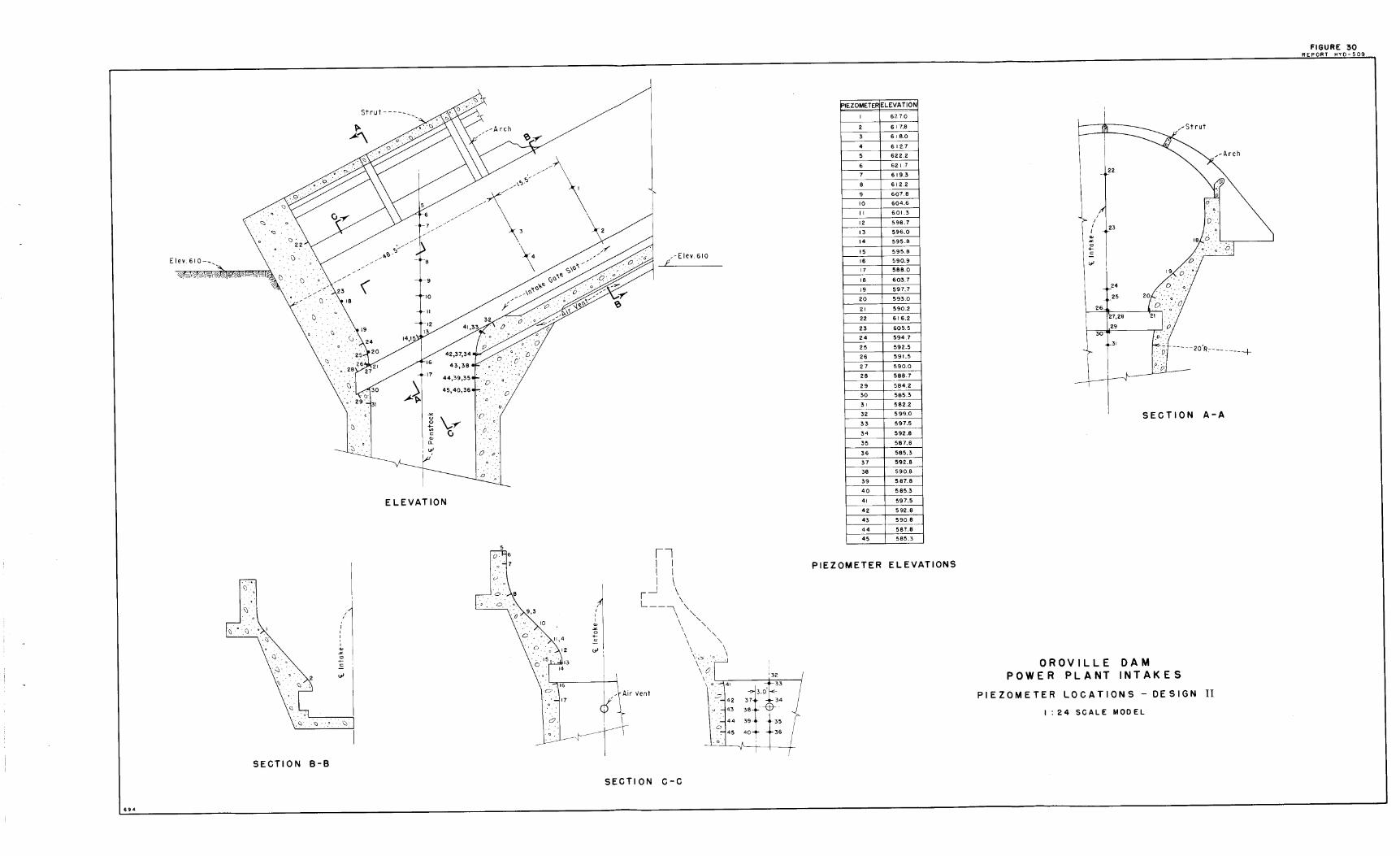
/ \ \ \ / /'\ ,.,~-/ 5/ // ,, 1
___ : ,//,,,/' \ /l.,/ ' 3
\ ,,-Elev. 610
"
4 . ,·
\)
~
~ ~-r 1·r 0
C C, . 0. a,
.-::,· "-,.J I .o 0
E LE VAT ION
17 I I I I
(] I
\) I
j1
I \
~ .. Cl ·x i
i_J \
I
L \
I
-- \ \,
'
\ ' I a,
\ '
~
'
~
\ '
C
12
\ ' ""'
\ '\ \ \ \a \ \
"" \0
\
·O
17
;::, I Io. ~··-r\· 1:~:: SECTION B-B
SECTION c-c
694
IPIEZOMETER ELEVATION
1 627.0
2 6 17.8
3 618.0
4 6 12.7
5 622.2
6 621 .7
7 619.3
8 612.2
9 607.8
10 604.6
11 601.3
12 598.7
13 596.0
14 595.8
15 595.8
16 590.9
17 588.0
18 603.7
19 597,7
20 593.0
21 590.2
22 616.2
23 605.5
24 594.7
25 592.5
26 591.5
27 590.0
28 588.7
29 584.2
30 585.3
31 582.2
32 599.0
33 597.5
34 592.8
35 587.8
36 585.3
37 592.8
38 590.8
39 587.8
40 585.3
41 597.5
42 592.8
43 590.8
44 587.8
45 585.3
PIEZOMETER ELEVATIONS
I I
a, ~
C +c
""
I I
I
26
30 l
23
.24
25
17,28
29
ri ~ ·•
D
r o/ -----2o'R--------+
OROVILLE POWER PL A NT
CJ.''
SECTION A-A
DAM INTAKES
PIEZOMETER LOCATIONS - DESIGN II
I: 24 SCALE MODEL
FIGURE 30 !!J;PORT HYO-~

694
1.0
9.0
8.0
7.0
6.0
5.0
4.0
3.0
2.0
0 N
:I:
i--: LL
I (I) 1.0 (/)
0 0.9 ...J 0.8
O 0.7 <{
W 0.6 :I:
0.5
0.4
0.
0.
0.
~ V = AVERAGE VELOCITY (Q/A) )~
IN 221
$ PENSTOCK.
l/2' INTAKE GATE REMOVED. I ' I I
~ V A-W/0 LIP EXTENSION w
(!)
B - WITH LIP EXTENSION Cl::
I I ~
~ :x: u
A - HL= 0.35 V2/2g----(/)
- Cl ~
J '/ ::i! ::>
I ::i!
II X
~-V/ ::i!
// II
IV/ j
r--- '-8 - HL= 0.31 V 2/2g
/; 2 3 4 5 6 7 8 9 10
DI $CHARGE - CFS x 1,000
A. HE A D LOSS VS. DI SC HA R G E
0 , I
,--See Detail A
FIGURE 31 REPORT HYD-509
tip: H RESERVIOR-H PIEZOMETER
INTAKE GATE REMOVED
6 SHUTTERS (240 FT.)
With Lip Extension .,__ Without Lip Extension
Dicharge 7960CFS - Res. Elev. 760
.:,c <.> 0
ID
-0 C w
0
0 N
:x: 0.,: NLJ..
0 -i
I a.
<J
8. DI F F E R E N T I A L PR E S S U RE S AC ROSS 6 S HU T T E R S
I'-0"-->l I _J.. ____ ). __ _
i : I I 0 i . I I N I I I
: I 10
• I Ii)
I I I
I
-l---1
• I ·w I
.N
I I
: ,!, I _,l I I I
I
k-l
: __ Channel Beam ,,,."'',,,,,., ,.
,//-Filler
,~~ /-24 VF 100
,~* /' ,,-Shutter
_y _____________ ---L __ _
DETAIL A (LIP EXTENSION)
OROVILLE DAM
POWER PLANT INTAKES
HEAD LOSS AND DIFFERENTIAL PRESSURES, 6 SHUTTERS- DESIGN III
DATA FROM I: 24 MODEL

694
4 3
6.p - FT H20
2
CHANNEL BEAM-,1
; I
I'- o'.'....>1 f-<-' I
I <:;> •'Q·' p !''.~·. I -()-1 •,:i' ••
I Y.._ • • ~ I
-U)
- I
/, I , I
/ , I /, I
I I
I
I I
I
< Ole-
IO I I I I
y - --~===========\ NO GAP
0
I II lll.lli..l..J
12 l
>-
' ' ' ' I II , ->1 1-<-I - 0
'\, I I
,-PI EZO METERS-, / '
/ ' It:/, 14 15 16 ',,~t
I I I
'-WITHOUT CHANNEL BEAM
', "-=f-mr6~ ,CHANNEL , I O · . _ _, I _ 1 • .-:;.o I C)J ·.;,
_ I 'j__ ....
BEAM
-U)
_, x-'I? I
I _ I I -Ol I I I I
j__j_
\
911
GAP
DISCHARGE- 8270 C.F.S. - RES. ELEV. 745
18 l
19 l
20 l
~
.J J:
+ Cl
~ "' >
I I I I
END BLOCK--,,
'" ~- - - - - - - 40
1 - - - - - - -
: I SHUTTER
21 22
~
lip= HRESERVOIR t HPIEZOMETER
SYMBOLS
<Ill NO GAP
• 911
GAP e CHANNEL BEAM REMOVED
OROVILLE DAM POWER PLANT INTAKES
0
1-N ~ <I
I')
'it'
DIFFERENTIAL PRESSURES ACROSS 5 SHUTTERS
EFFECT OF GAP BETWEEN SHUTTERS AND CHANNEL BEAM
FIGURE 32 REPORT HYO- 509

0
-n
O 0 • Cr)
Cn
4s
0 0 0 rn
C --4
rn
(/)
0
U)
E
S3
811
SS
38d
- IVII
N3
el3
Ad
l a
A (IA 0 O
Ap - FT H2O
>100
18
0N
3
0
0 rn
5' -6'
5 I/2 1H "c-
0
7
fD CD
CD 0
a. O
A O
I I I • (IA -
I N '0 O
• Ap FT H2 O
0
rn
0 co r0 C)
-
r
S3
AV
INI I
NV1d
2:J3M
Od
INVO
31
11
A02
:i0
TR
AS
HR
AC
K S
UP
PO
RT
ME
MBE
RS
IN P
LA
CE
02
L .A
213 "S
32:i
0 E> cn- 0 " I I D
m u)
rn <
03 o
a) 0 0 I -0
-n cn N 0
-13 rn o 73 0 ▪ C
rT1
0 4.1.1
0 co

7-1750 (lo-64)
OONVERSION FACTORS-BRITISH TO METRIC UNITS OF MEASUREMENT
'!he following conversion factors adopted cy the Bureau or Reclamation are those published by the .Amel'ican Societv' ror Testi.Dg and Materials (AS'Dl Metric Practice Guide, .Tanwll7 1964) except that additional factors (*) c~ used in the Bureau have been added. Further discussion or definitions or quantities and units is given on pages 10-11 or the AS'll,I Metric Practice Guide.
'!he metric units and conversion factors adopted cy the AS'.IM are based on the "International &Ystem or Units" (desigus.ted SI ror &Ysteme Intel'DBtional d 1Unites), fixed by the International Committee ror Weights and Measures; this system is also known as the Giorgi or MKSA. (meter-kilogram (mass)-eecODd-ampere} system. 'ftlis system has been adopted by the International Organization ror standardization in ISO Recamnendation R-31.
'!he metric technical unit or force is the kilogram-force; this is the force which, when applied to a body havi.Dg a mass or 1 kg, gives it an acceleration or 9.80665 111/sec/sec, the standard acceleration or :free fall toward the earth's center ror sea level at 45 deg latitude. '!he metric unit or force in SI units is the newton (N), which is defined as that force which, when appl.i'ld to a body havi.Dg a mass or l kg, gives it an acceleration or l 111/sec/sec. 'ftlese units must be distinguished rran the (inoonstent) local weight or a body having a mass or l kg; that is, the weight or a body is that force with which a body is attracted to the !!Bl"th and is equal to the mass or a body lllllltipl.ied cy the acceleration due to gravity. Holrever, because it is general practice to use "pound" rather than the technio~ correct term "pound-force," the term "kilogram" (or derived mass unit) has been US'ed in this guide instead or "kilogramrorce" in expressiDg the conversion rectors ror roroes. 'ftle newton unit or rorce will rind inoreasiDg use, and is essential in SI units.
~
QUANTITIFS AND UNITS OF SPACE
1611.tiE:J:l !!z To obtain
LENGTH
Mil. 25.4 c-~>. • Miol'OD Inchss 25.4 (enc~). , • • 111.lliEters
2.54 c-~t . • Centimeters Feet • 30,48 <-~ ... • Centimeters
0.3048 ( -~ )* • • • Meters 0 .0003048 ( ezact~ )* • • Kilomsters
Yards • ••••• O. 9144 ( ezact~) • • Meters Ml.lss (statute) 1,609.~ (exact~)* • • Meters
· l.609~ tezact:J:l2 • Kilometers
ABBA
Square :lnches. 6.4'16 (exao~) • • Square centimeters Square feet. 929,03 (exact~)* •• • Square centimeters
0.092903 (exec~) • Square meters Square7arda 0.1136127 •• • Square meters Acres •••• 0.4()4691! •• • Hectares
4,046.~ •••• • Square meters 0 .0040469* • • Square kilometers
Square miles 2.58999 •• • !!guare kilometers
VOLUMB
CUbic :lnchss 16.38'71 •• • cubic cent:Lmaters CUbic tsst • 0.0283168 • CUbio meters CUbicnrds. 0.'764555. • cubic meters
CAPACITY fi'llid ounces (U.S.) 29.57')7 •• • cubic centimeters
29.5729 •• • Ml.lliliters Liquid pints (U.S.) 0,473179. • cubic decimeters
0,473166. • Liters Quarts (U.S.). 9,463.58 ••• • CUbic centimeters
Gallons (U.S.) 0,946358. • Liters
3,ffl.43* •• • CUbic oentilmters . 3.78543 • • CUbic decimeters 3.78'33 ••• • Liters 0 .00378543* • • cubic meters
Gall.ems (U.K.) 4,54609 • • cubic decimeters 4.54596 • • Liters
Cubic tsst • 28.3160. • Liters CUbic 781'ds '764.5S- • • Liters Acre-tsst. 1,233,S- • Cubic meters
• 112331500* • Liters
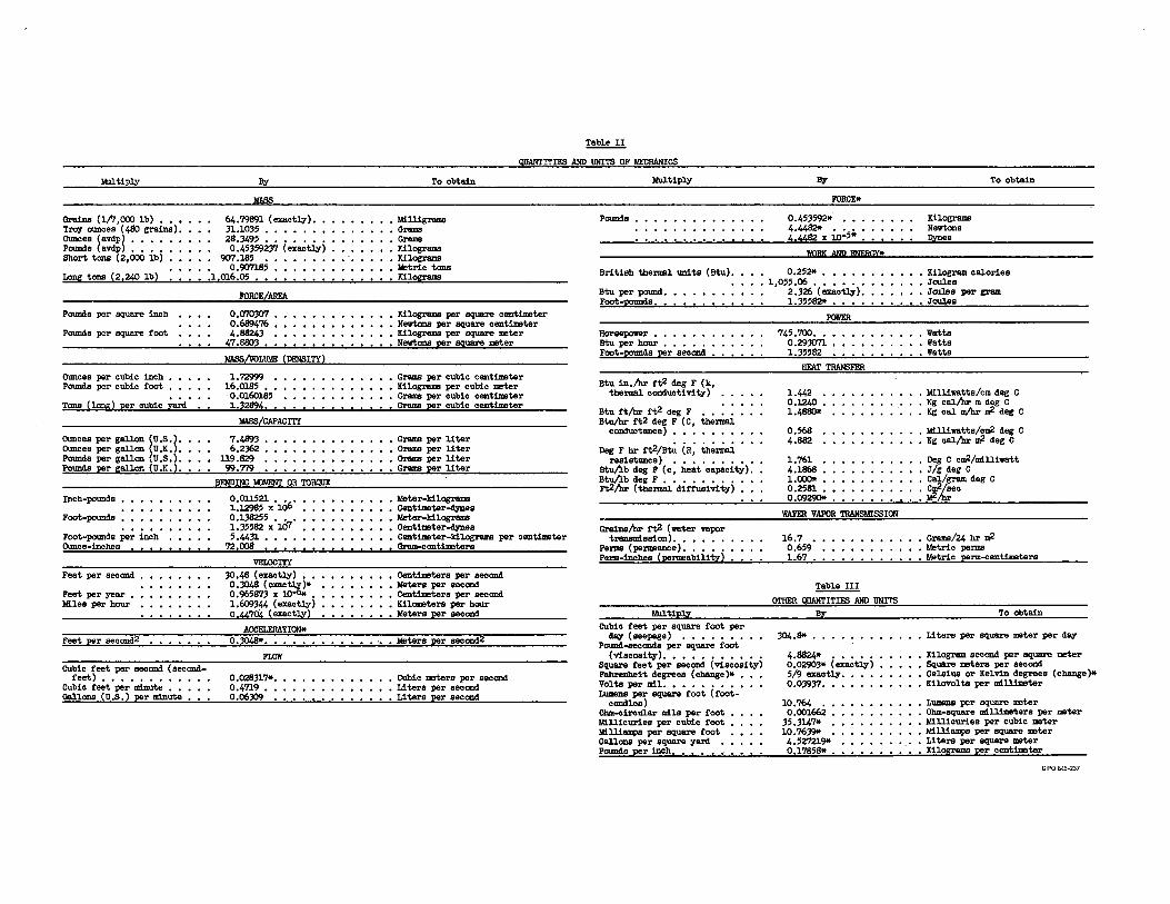
Mlltipl:f
Grains (l/7,000 lb) , • • Trey ounces ( 480 grains). Ounoes (avdp) • • • • POllllds (avdp) • , , , Short tons ( 2 ,ooo lb)
!l.
64, '79891 ( exact:cy) , • 31,1035 •• , , , • , 28.3495 , , , • , •• 0,45359237 (exact:cy)
907.185 •• , , • 0. 90'7l8S • • •
Lang tons (21240 lb) ,1 1016,05 • ,
Pounds per square inch
Pounds per square foot
Ounoes per cubic inch • , • Pounds per cubic foot • • •
Tons ( lang) per cubic nrd'
Ounces per gallon (U ,S.) • Ounoes per gallon (U ,K,) • POllllds per gall.an (U ,S, ~ , P~s per gallon (U,K,.
Inch-pounds •
Foot-pOllllds •
Foot-pounds per inch Ounoe-:1.J,chas
Fest per seccmd
Feet per year • Ml.lea per hour
~.!.l!!!:..,S!!ccmdI
cubic fest per seccmd ( seccmd-fest) •• , , , , , , , , , ,
CUbic rest per minute • • • • • ~l-ons (U ,S, ) per ml.nuts , • •
joRc:Ef!REA
0,0'10307 , 0,689476 , 4,118243 ,
47,8803 •• MASS/VOLlll!E (DENSITI)
1,72999 , 16,0185 • ·, . 0,0l.6018; 1,32894. ,
IIA!!SLCAPACIT?'
7,4893 • , , • • 6,2362 ••• , ,
119,829 •••• , 99.719 • , , , ,
BENDING MJMENT OR i'ORQIJE
0,011;21, , , l,l.2985 X l.()6 0.138255 ••• 1,35582 X 10⁷ ;,4431 ••••
7;!,008 • • • •
VELOCITI 30,48 (enct:cy) • , 0,3048 (exac:C* 0,965873 X 10 , 1,609344 ( enct:cy) 0,¥,704 (exactJ,y)
~I!)II* 0.:3048* •••
FLOW
0,028317*. 0,4719 •• 0,06309 ,
~
QUANTITil!S ARD UNITS OF MECHANICS
To obtBin
• Milligrama , Grams • Grams • Kilograms • Kilograms • Metric tons • Kilograms
• Kilograms per square centimeter • Newtons per square centimeter , Kilograms per square meter • Newtons per square meter
• Grams per cubic cent:Lmater • Kilograms per cubic meter
Grams per cubic cent:Lmater Grams per cubic centimetar
• Grams per liter • Grams per liter • Grams per liter , Grams per liter
• Meter-kilograms , Centimots~s • Meter-kilograms • Centimotsr-41Des , Centimetar-kilograma per centimeter ..__ Orl!!ll-c,ent~rs_
, Centimeters per seccmd • Yetera per seccmd , Centimeters per seccmd • Kilometers per hour • Meters per seccmd
• Meters per -g¢.I
• CUJ>io meters per seccmd • Liters per seccmd • Liters per seccmd
l!llltip:cy
Pounds
Bri tisb tbermal UDi ts ( Btu) ,
Btu per pound, Foot-pounds.
Horsepower • , Btu per hour • Foot-:po,mds per seccmd
Btu in./hr rt2 deg F (k, tbermal ccmductivity-)
Btu rt/hr rt2 deg F , , , • • Btu/hr t't2 deg F ( C, tbermal
ccmductsnce) • • • , , • •
Deg F hr rt2/Bt.; (R; ih.;.,;..j_ resistsnce) • • • • • • • • ,
Btu/lb deg F ( c, heat capsci ty) • Btu/lb deg F , , , , , , , • , , Ft2/hr ( thermal dii't'usivi ty)
Grains/hr rt2 ( water vapor treosml.ssicm). , • • • •
Perms ( permeence). • • • • Pei,n..__~bes (permeability)
141ltiP1:r CUbic feet per square foot per
dq (seepage) • ' • • • • • • Pound-seccmds per square foot
117
l'OllCE*
0,453592* , , , 4,4482* ••• · • ~x_10-5* _,
WQRtC AND INIBOI*
• 0.252* • , , •• • 1,o;;,06 •••••• • 2 .326 ( exact:cy) •
l,35582tt , , •
~
745,700, ••• , 0.293071 • , • 1,3;;_§2-----'----'---'
HEAT TRANSFER
1,442 • 0.1240 • 1,4880*
0,'68 4,882
1.761 4,1868 • 1.000* • 0.2,si •• 0.09290* •
WATER VAPOR TRAHSMISSION
16.7 • 0,659 l.,67.
~ OTHER QUAIITITIFS A!iD '(!ICr.l'§_
.!!Z.
304,s,, •••
( viscosi v). . . , . . . . . . . Square feet per seccmd (viscosity-) l'ahrenhei<t degress ( challge )* •
4,11824* , , , , , 0,02903* (exactq) ;/9 exactq. 0.03937 •• Volts per ml.l, , , , , , , , ,
Lumens per square foot ( t'oot-candlea)
Ohm-cireuJ.ar ml.l.a per root • 111.llicuries per cubic foot 111.lliamps per square root Oallons per square yard Pounds per inch, • • • • ,
10.764 •• 0,001662 •
35,3147* , 10.7639* ,
4.527219* 0.l78581t •
Kilograms Newtons .l?.!!!!S
To obtain
• Kilogram calories • Joules , JmJ.es per gram ..__;rouJ,es
, Watts • Watts , Watts
• Milliwatts/om deg C • Kg cal/hr m deg C , Kg cal IIVhr 'IV- deg C
, Milliwatts/cn,2 deg C • Kg cal/hr ..;! deg C
, Deg C c'IV-/mllliwatt , J/g deg C :~dsgC
~
• Grems/24 hr ..;! • Metric perms • Metric perm~_entinleters
To obtBin
, Liters per square meter per dq
• Kilogram seccmd per square mater • Square metsre per seccmd • cel.aius ar Kelvin degrees (change)* • Kilovolts per ml.llimeter
• LUIIIBIIS per square meter , 0llm-square mlllimeters per meter • Millicuries per cubic meter • Milliamps per square meter • Li tars per square meter • Kilograms per centimeter
GPO 845-237

ABSTRACT
Hydraulic model studies helped determine head losses, differential pressures, vortex action, and general pressures for three proposed designs for the intake structure of the Oroville Dam underground powerplant. Agriculture and fish propagation downstream from the dam require control of the temperature of water released through the powerplant. This control is accomplished by withdrawing water from selected reservoir depths through ports or opened shutters placed along intake structures which slope up the side of the reservoir. Design I consisted of 650-footlong trapezoidal channel with semicircular covering shells, a 60-footlong trashrack-covered port at the base, and five additional 40-foot-long ports Flow through each port was controlled by thin semicylindrical shutters. The design was abandoned because of possible instability of the semicylindrical shutters and complicated, submerged mechanisms necessary to engage, move, and latch the shutters. Design II consisted of sloping channels with larger trapezoidal cross sections and continuous arched trashracks the full length of the structures. Under the trashracks, flat 40-foot-long by 45-foot-wide control shutters covered the intake channels. The shutters could be removed from the channels or reinstalled as reservoir level or temperature requirements changed. Design II was tested thoroughly and accepted for prototype use. However, unexpected foundation problems required structural modifications, culminating in Design m. This design utilized rectangular channels with lighter trashrack arches supplemented by tension beams across the channel at the base of each arch. Design m was adopted.
ABSTRACT
Hydraulic model studies helped determine head losses, differential pressures, vortex action, and general pressures for three proposed designs for the intake structure of the Oroville Dam underground powerplant. Agriculture and fish propagation downstream from the dam require control of the temperature of water released through the powerplant. This control is accomplished by withdrawing water from selected reservoir depths through ports or opened shutters placed along intake structures which slope up the side of the reservoir. Design I consisted of 650-footlong trapezoidal channel with semicircular covering shells, a 60-footlong trashrack-covered port at the base, and five additional 40-foot-long ports Flow through each port was controlled by thin semicylindrical shuttei;s. The design was abandoned because of possible instability of the semicylindrical shutters and complicated, submerged mechanisms necessary to engage, move, and latch the shutters. Design II consisted of sloping channels with larger trapezoidal cross sections and continuous arched trashracks the full length of the structures. Under the trashracks, flat 40-foot-long by 45-foot-wide control shutters covered the intake channels. The shutters could be removed from the channels or reinstalled as reservoir level or temperature requirements changed. Design II was tested thoroughly and accepted for prototype use. However, unexpected foundation problems required structural modifications, culminating in Design m. This design utilized rectangular channels with lighter trashrack arches supplemented by tension beams across the channel at the base of each arch. Design III was adopted.
ABSTRACT
Hydraulic model studies helped determine head losses, differential pressures, vortex action, and general pressures for three proposed designs for the intake structure of the Oroville Dam underground powerplant. Agriculture and fish propagation downstream from the dam require control of the temperature of water released through the powerplant. This control is accomplished by withdrawing water from selected reservoir depths through ports or opened shutters placed along intake structures which slope up the side of the reservoir. Design I consisted of 650-footlong trapezoidal channel with semicircular covering shells, a 60-footlong trashrack-covered port at the base, and five additional 40-foot-long ports Flow through each port was controlled by thin semicylindrical shutters. The design was abandoned because of possible instability of the semicylindrical shutters and complicated, submerged mechanisms necessary to engage, move, and latch the shutters. Design II consisted of sloping channels with larger trapezoidal cross sections and continuous arched trashracks the full length of the structures. Under the trashracks, flat 40-foot-long by 45-foot-wide control shutters covered the intake channels. The shutters could be removed from the channels or reinstalled as reservoir level or temperature requirements changed. Design II was tested thoroughly and accepted for prototype use. However, unexpected foundation problems required structural modifications, culminating in Design m. This design utilized rectangular channels with lighter trashrack arches supplemented by tension beams across the channel at the base of each arch. Design III was adopted ..
ABSTRACT
Hydraulic model studies helped determine head losses, differential pressures, vortex action, and general pressures for three proposed designs for the intake structure of the Oroville Dam underground powerplant. Agriculture and fish propagation downstream from the dam require control of the temperature of water released through the powerplant. This control is accomplished by withdrawing water from selected reservoir depths through ports or opened shutters placed along intake structures which slope up the side of the reservoir. Design I consisted of 650-footlong trapezoidal channel with semicircular covering shells, a 60-footlongtrashrack-covered port at the base, and five additional 40-foot-long ports Flow through each port was controlled by thin semicylindrical shutters. The design was abandoned because of possible instability of the semicylindrical shutters and complicated, submerged mechanisms necessary to engage, move, and latch the shutters. Design II consisted of sloping channels with larger trapezoidal cross sections and continuous arched trashracks the full length of the structures. Under the trashracks, flat 40-foot-long by 45-foot-wide control shutters covered the intake channels. The shutters could be removed from the channels or reinstalled as reservoir level or temperature requirements changed. Design II was tested thoroughly and accepted for prototype use. However, unexpected foundation problems required structural modifications, culminating in Design m. This design utilized rectangular channels with lighter traijhrack arches supplemented by tension beams across the channel at the base of each arch. Design III was adopted.
Hyd-509 Bucher, K. G. HYDRAULIC MODEL STUDIES OF THE OROVILLE DAM POWERPLANT INTAKE STRUCTURES--CALIFORNIA DEPARTMENT OF WATER RESOURCES--STATE OF CALIFORNIA Laboratoryreport, BureauofReclamation, Denver, 14 p, 34fig, Stab, 7ref, 1965
DESCRIPTORS-- *hydraulics/ *head losses/ *pressures/ hydraulic models/ flow control/ trapezoidal channels/ *vortices/ hydraulic structures/ underground powerplants/ intake gates/ trashracks/ *intake structures/ temperature/ model tests/ temperature control/ inlets/ research and development/ fish/ agriculture/ ports IDENTIFIERS-- *Oroville Dam power/lant/ sloping intake structures/ California/ reentrant inlets/ shutters hydraulic design/ temperature control shutters
Hyd-509 Bucher, K. G. HYDRAULIC MODEL STUDIES OF THE OROVILLE DAM POWER PLANT INTAKE STRUCTURES--CALIFORNIA DEPARTMENT OF WATER RESOURCES--STATE OF CALIFORNIA Laboratoryreport, BureauofReclamation, Denver, 14 p, 34fig, Stab, 7ref, 1965
DESCRIPTORS-- *hydraulics/ *head losses/ *pressures/ hydraulic models/ flow control/ trapezoidal channels/ *vortices/ hydraulic structures/ underground powerplants / intake gates/ trashracks / *intake structures/ temperature/ model tests/ temperature control/ inlets/ research and development/ fish/ agriculture/ ports IDENTIFIERS-- *Oroville Dam power/lant/ sloping intake structures/ California/ reentrant inlets/ shutters hydraulic design/ temperature control shutters
Hyd-509 Bucher, K. G. HYDRAULIC MODEL STUDIES OF THE OROVILLE DAM POWERPLANT INTAKE STRUCTURES--CALIFORNIA DEPARTMENT OF WATER RESOURCES--STATE OF CALIFORNIA Laboratory report, Bureau of Reclamation, Denver, 14 p, 34 fig, 6 tab, 7 ref, 1965
DESCRIPTORS-- *hydraulics/ *head losses/ *pressures/ hydraulic models/ flow control/ trapezoidal channels/ *vortices/ hydraulic structures/ underground powerplants/ intake gates/ trashracks/ *intake structures/ temperature/ model tests/ temperature control/ inlets/ research and development/ fish/ agriculture/ ports IDENTIFIERS-- *Oroville Dam powerplant/ sloping intake structures/ California/ reentrant inlets/ shutters/ hydraulic design/ temperature control shutters
Hyd-509 Bucher, K. G. HYDRAULIC MODEL STUDIES OF THE OROVILLE DAM POWERPLANT INTAKE STRUCTURES--CALIFORNIA DEPARTMENT OF WATER RESOURCES--STATE OF CALIFORNIA Laboratory report, Bureau of Reclamation, Denver, 14 p, 34fig, 6 tab, 7 ref, 1965
DESCRIPTORS-- *hydraulics/ *head losses/ *pressures/ hydraulic models/ flow control/ trapezoidal channels/ *vortices/ hydraulic structures/ underground powerplants / intake gates/ trashracks / *intake structures/ temperature/ model tests/ temperature control/ inlets/ research and development/ fish/ agriculture/ ports IDENTIFIERS-- *Oroville Dam power1lant/ sloping intake structures/ California/ reentrant inlets/ shutters hydraulic design/ temperature control shutters