preparation of pure iron and iron-carbon alloys bulletinofthebureauofstandards. [voi.13...
TRANSCRIPT

PREPARATION OF PURE IRON AND IRON-CARBONALLOYS
By J. R. Cain, E. Schramm, and H. E. Cleaves
CONTENTSPage
I. Introduction 2
II. Making the electrolytic iron 4III. Melting the electrolytic iron 7
1. Ftimaces 8
(a) Electric furnaces 8
(6) Gas furnaces 11
2. Crucibles 13
IV. Procedure in making alloys 16
V. Discussion of the sources of contamination 19
1. Silicon 19
2. Sulphur 20
3
.
Manganese and phosphorus 20
4. Copper 21
5 Nickel and cobalt 21
6. Magnesium 21
7. Oxygen 21
VI. Spectroscopic examination 22
VII. Methods of chemical analysis 22
1. Carbon 23
2. Sulphtir 23
3. Silicon 23
4. Phosphorus 24
5. Manganese 24
6. Copper 24
7. Magnesium 24
8. Nickel and cobalt 25
VIII. Summary '. 25
Bibliography 26
I

2 Bulletin of the Bureau of Standards [Voi 13
I. INTRODUCTION
The fundamental importance of the iron-carbon thermal equi-
librium diagram in the scientific metallurgy of iron and steel and
its utility to practical workers have long been realized, and accord-
ingly this subject has received attention from many points of view
and from many investigators during the past two decades.
In view of this fact, it might seem superfluous to add to the
existing literature except for the following considerations : Earlier
workers have for the most part confined their attention to special
portions of the diagram or to disputed questions of theory. Their
thermal studies have not been carried out with the degree of
accuracy now attainable. They have practically without ex-
ception employed commercial materials of varying degrees of
purity. In two papers published in 1913^ Prof. H. M. Howe, as
a result of a thorough examination of the literature, has fixed the
most probable position of the equilibrium lines. His net con-
clusions are that ''this calculated line is not entitled to great weight
because of the weakness of the evidence," and that ''much better
data are needed, reached with pure materials and with the manycauses of error reduced to a minimum." In Table i, compiled
from Prof. Howe's papers, are given analyses of the materials
used in some of the more important recent investigations. Aglance at the table will show the justice of the conclusions quoted
above. The analyses are incomplete even for the impurities ordi-
narily determined, and entirely ignore the possible presence of
other impurities, such as Cu and Ni; but so far as they go, they
indicate a very appreciable degree of contamination by S, Si, Mn,
elements which we know exert a marked effect on the critical
ranges. It may be said that the iron-carbon diagram has never
been worked out with pure iron-carbon alloys. The present paper
describes the preparation of a series of high degree of purity, to
be used as the basis of a more accurate study of the equilibrium
diagram than has heretofore been attempted.
1 Aei, the Equilibrium Teint)erature for Ai in Carbon Steel, Bull. Am. Inst. Min. E., p. 1066; 1913.
A Discussion of the Existing Data as to the Position of Aes, Bull. Am. Inst, Min. E., p. 1099.

Cain, Schramm.lCleaves J
Pure Iron and Iron-Carbon Alloys
TABLE 1
Composition of Iron-Carbon Alloys Used by Various Investigators in Determinations
of Critical Points
No, Authority Date
Composition of specimens
C Si Mn P S
I Carpenter and l^eelinz o- 1904
Per cent
0.38
1.85
3.98
4.50
2.63
2.85
2.85
.39
.95
1.14
Per cent
0.05
.09
Per cent
Trace.
Per cent
0.03
Per cent
0.01
2 ... do ,
3 do
4 . do .12
5 do
5A do
6 ... do Trace?
.03
.06
.40
7 Heyn b 1904 .04
.04
.09
8 do
9
10
Rosenhain c (on Brayshaw's steel A2)
do
1910 .014 .018
11 1908
1903
1.00
.64
.64
.93
.93
1.50
1.15
1.16
1.14
.23
.92
.027
.105
.214
.227
.235
.244
.382
.40
.563
.59
.73
.92
.25
12 Charpy and Grenet *
13 do
14 .. . do
15 do
16 do
17 Brayshaw / No. W4 1910
1910
.21
.10
.09
.039
.14
.31
.37
.40
.05
.123
.26
.24
.05
.05
.05
Nil.
.22
.16
.15
.17
.07
.123
.011±
.014
.014
.013
.009
.005
.015
.013
.013
.013
Nil.
.012±
18 Brayshaw No. W2 .023
19 Brayshaw No. A2 .018
20 1913
1912
1913
.010
21 Levy .011
?> Howe and Levy * .024
23 do .013
.039
.039
.039
.050
.027
.103
.18
.144
.141
.14
.028
24 do .010
25 .. do .010
26 do .010
27 do .007
28 do .004
29 do .014
.013
.018
.012
.009
.012
30 do .013
31 do .013
32 do .019
33 do .. . .011
o Carpenter and Keeling, Journal Iron and Steel Inst., 65, p. 244; 1904, No. i; Collected Researches of
the Nat'l Phys. Lab., 1, p. 227 .
& Heyn, Verh. des Vereins zur Beforderung des Gewerbfleisses, p. 371; 1904.
c Rosenhain, Proc. Inst. Mech. Engrs., p. 688; 1910, parts i and 2.
d Benedicks, Jour. Iron and Steel Inst., 77, p. 218; 1908, No. 2.
< Charpy and Grenet, Bulletin Soc. d'Encouragement pour I'lndustrie Nationale, p. 480; 1903, No. i.
/ Brayshaw, Proc. Inst. Mech. Engrs., pp. 525, 537, 656, 670; 1910, parts i and 2.
g Howe, Bull. Amer. Inst. Min. Engrs., p. 1068; 1913, No. i.
A Howe and Levy, Bull. Amer. Inst. Min. Engrs., p. 1076; 1913, No. i.

4 Bulletin of the Bureau of Standards. [Voi. 13
For the production of pure iron on a fairly large scale, the elec-
trolytic refining method was obviously most suitable and was there-
fore adopted in this work. Pure carbon was made by calcining
in a Dixon graphite crucible the pure sugar used as stock for Bureau
of Standards analyzed sample No. 17. The latter contains, as the
only impurity of importance for present purposes, 0.003 P^^" cent
ash, and the carbon obtained from it has an ash content of 0.17
per cent.
II. MAKING THE ELECTROLYTIC IRON
The electrolytic method, using soluble anodes, has been fre-
quently employed in similar investigations ^ and its essentials
are well known, so that we give details only for the sake of com-
pleteness and because, in one respect, our method deviates from
that usually followed, namely, in the use of porous anode compart-
ments. The first iron was made on a small scale. The essential
details of the bath are as follows : Two cylindrical anodes of ingot
iron ^ about 2 inches in diameter by 5 inches long, contained in
porous clay cups ; three cathodes of sheet iron, each 4 inches square
;
electrolyte, 25 to 30 per cent FeCL solution (made by dissolving
the ingot iron in chemically pure hydrochloric acid), prepared as
nearly neutral as possible; current density about 0.5 to 0.7 ampere
per square decimeter; temperature during electrolysis approxi-
mately that of the room. No attempt was made to determine the
yield or to secure high ciurent efficiency. Good adherent deposits
were obtained, the greatest thickness being about 0.5 cm. Owingto the unfavorable cm-rent distribution when working with anodes
and cathodes of such unequal sizes, the thickness of deposit wasnot uniform all over the plates. Qualitative tests of the sludge
from the anode cells showed that there was an accumulation of
manganese and copper derived from anodic impurities. Theporous cups therefore seemed to be of service in preventing anode
impurities from migrating to the cathodes, and they were accord-
ingly used in one of the larger baths to be described later. In
another similar tank the cups were omitted. Table 2 shows that
the cathode deposits from the bath without the t:'ups were a little
higher in copper than the others but were otherwise of similar
2 See bibliography at end of this paper.
3 Analysis as follows: C, 0.016; S, 0.022; Mn, 0.029; P, o.ooi; Si, 0.002; and Cu, 0.15.

Cain, Schramm,']Cleaves J
Pure Iron and Iron-Carbon Alloys
quality. It was found that there was much oxidation of the sur-
face layers of electrolyte as the electrolysis went on, resulting in
the production of basic salts of iron, which floated in the bath andwhich migrated to some extent to the cathodes. With the inten-
tion of avoiding or minimizing this oxidation, the small bath wasprovided with a hydraulically sealed cover having windows for
observation and conduits for the current leads. The air in the
space over the electrolyte was displaced with purified carbon
dioxide and the electrolysis conducted as before. This methodled to no marked improvement and it was abandoned, especially
as there seemed to be a tendency toward higher percentages of
carbon in the cathodic deposits. Although the greater part of
the sediment settled to the bottom, the bath was never quite free
from turbidity caused by these basic salts, and there is no doubt that
the deposits were contaminated by them in slight degree. This
was of no consequence, inasmuch as these impurities were either
volatilized or were reduced to iron in subsequent melting opera-
tions. The analysis of the iron stripped from cathodes of the small
electrolytic bath is given in Table 2. About 2 or 3 kg was madein this bath.
TABLE 2
Analyses of Electrolytic Iron from Various Sources
Source C S P Mn Si Cu NiandCo
Totalimpurity
Anal3^isby-
10,6
2c,b
3d,b
4«
Per cent
0.004
.004
.004
.004
.063
.008
.008
.009
Per cent
0.002
.003
.006
.004
.002
Trace
.004
.003
Per cent
Trace
Trace
Trace
Trace
0.005
.002
Trace
Trace
Per cent
Trace
Trace
Trace
Trace
0.009
.009
Trace
Trace
Per cent
0.003
.006
.008
.005
.005
.014
.006
.006
Per cent
0.006
Trace
.006
.008
Per cent
0.011
.011
• Oil
.011
Per cent
0.026
.024
.035
.033
.084
,033
.029
.024
B.S.
B.S.
B.S.
B. S.
5/ Miiller
6g Stead
7^^ . .011
.006
B. S.
8t B. S.
a B. S. (with porous cups).
& Bureau of Standards analysis of anodes from which this iron was made: C, 0.013 per cent; S, 0.020 per
cent; P, 0.003 per cent; Mn, 0.025 per cent; Si, 0.003 per cent; Cu, 0.024 per cent; and Ni+Co, 0.021 per
cent. (Cf. Burgess and Crowe, this Bulletin, 10, p. 342; 1914.
c B. S. (with porous cups).
d B. S. (without porous cups).
e B. S. (from small tank).
/ A. Miiller, Metallurgie, 6, p. 152; 1909.
S H. C. H. Carpenter.'"' Langbein-Pfanhauser.t C. F. Burgess.
Bulletin of the Bureau of Standards [Vol. 13
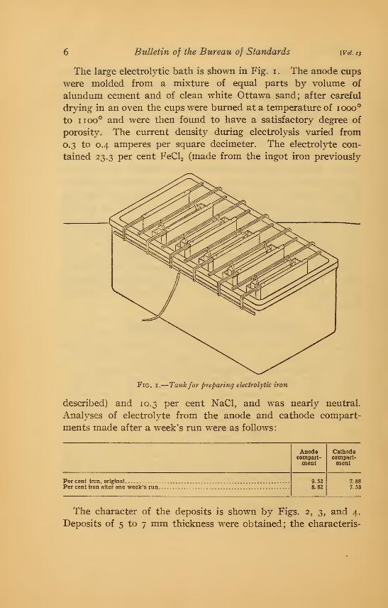
The large electrolytic bath is shown in Fig. i . The anode cups
were molded from a mixtm-e of equal parts by volume of
alundum cement and of clean white Ottawa sand; after careful
drying in an oven the cups were burned at a temperature of 1000°
to 1100° and were then found to have a satisfactory degree of
porosity. The current density during electrolysis varied from
0.3 to 0.4 amperes per square decimeter. The electrolyte con-
tained 23.3 per cent FeCla (made from the ingot iron previously
Fig. I.
—
Tankfor preparing electrolytic iron
described) and 10.3 per cent NaCl, and was nearly neutral.
Analyses of electrolyte from the anode and cathode compart-
ments made after a week's run were as follows:
Anodecompart-ment
Cathodecompart-ment
Per cent iron, original
Per cent iron after one week's run.9.528.82
7.887.53
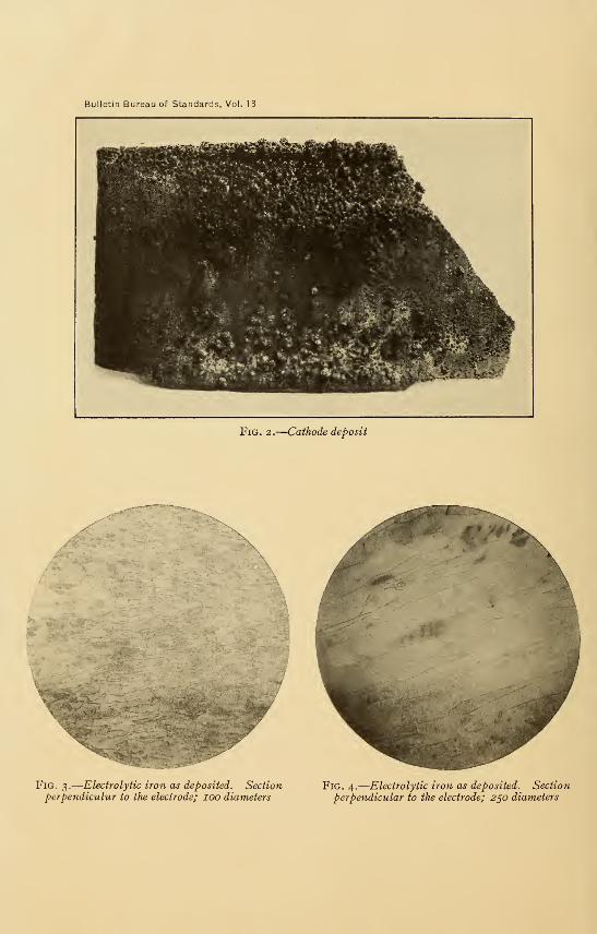
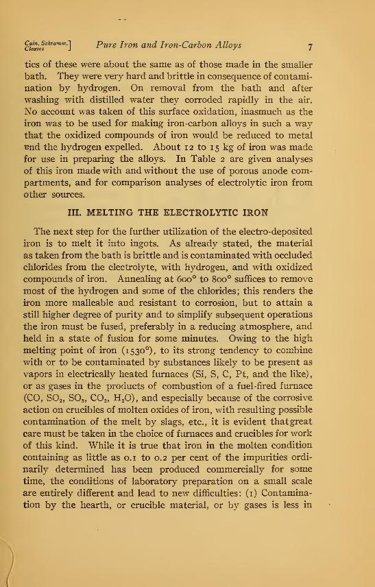
The character of the deposits is shown by Figs. 2, 3, and 4.
Deposits of 5 to 7 mm thickness were obtained; the characteris-
Bulletin Bureau of Standards, Vol. 13
11^iim^^g
Fig, 2.
—
Cathode deposit
Fig. 3.
—
Electrolytic iron as deposited. Sectionperpendiculur to the electrode; lOO diameters
Fig. 4.
—
Electrolytic iron as deposited. Section
perpendicular to the electrode; 250 diameters
ctlavef^'''"''^']Pure Iron and Iron-Carbon Alloys 7
tics of these were about the same as of those made in the smaller
bath. They were very hard and brittle in consequence of contami-
nation by hydrogen. On removal from the bath and after
washing with distilled water they corroded rapidly in the air.
No account w^as taken of this surface oxidation, inasmuch as the
iron was to be used for making iron-carbon alloys in such a waythat the oxidized compounds of iron would be reduced to metal
Bnd the hydrogen expelled. About 1 2 to 1 5 kg of iron was madefor use in preparing the alloys. In Table 2 are given analyses
of this iron made with and without the use of porous anode com-
partments, and for comparison analyses of electrolytic iron from
other sources.
III. MELTING THE ELECTROLYTIC IRON
The next step for the further utilization of the electro-deposited
iron is to melt it into ingots. As already stated, the material
as taken from the bath is brittle and is contaminated with occluded
chlorides from the electrolyte, with hydrogen, and with oxidized
compounds of iron. Annealing at 600° to 800° suffices to remove
most of the hydrogen and some of the chlorides; this renders the
iron more malleable and resistant to corrosion, but to attain a
still higher degree of purity and to simplify subsequent operations
the iron must be fused, preferably in a reducing atmosphere, and
held in a state of fusion for some minutes. Owing to the high
melting point of iron (1530°), to its strong tendency to combine
with or to be contaminated by substances likely to be present as
vapors in electrically heated furnaces (Si, S, C, Pt, and the like)
,
or as gases in the products of combustion of a fuel-fired furnace
(CO, SO2, SO3, CO2, H2O), and especially because of the corrosive
action on crucibles of molten oxides of iron, with resulting possible
contamination of the melt by slags, etc., it is evident that great
care must be taken in the choice of furnaces and crucibles for work
of this kind. While it is true that iron in the molten condition
containing as little as o.i to 0.2 per cent of the impurities ordi-
narily determined has been produced commercially for some
time, the conditions of laboratory preparation on a small scale
are entirely different and lead to new difficulties: (i) Contamina-
tion by the hearth, or crucible material, or by gases is less in
Bulletin of the Bureau of Standards [Vol. 13
I
to
d
large-scale operations,
owing to the relatively
smaller surface exposed
compared with the
weight of metal being
handled; (2) additions,
such as ferroalloys,
aluminum, or titanium
for purification of the
melt, as used com-
mercially, are not per-
missible in an investi-
gation of this kind; (3)
the use of slags for
protection from the
products of combustion
or for eliminating im-
purities and controlling
composition in desired
ways is excluded. Theimportance of the con-
ditions for melting pure
iron and its alloys to
secure products of very
high purity does not
seem to have been rec-
ognized sufficiently in
the past, and we shall
therefore give full de-
tails of our methods.
1. FURNACES
(a) EivECTRic Fur-
naces.—For ease and
convenience of manip-
ulation a furnace used
Cain, Schramm, '\
Cleaves JPure Iron and Iron-Carbon Alloys
for melting pure iron should maintain continuously a temperature
of not less than 1600°. The temperature required eliminates
furnaces wound with nickel or nichrome; molybdenum or plati-
num-wound furnaces are not desirable for work in high vacua,
owing to volatiliza-
tion of these mxCtals
with resulting con-
tamination of the
melt and destruction
of the heater. Timg-
sten windings could
no doubt be used, but
no suitable fiunace
of this type was avail-
able at the Bureau.
Our work with elec-
tric furnaces has been
confined, therefore, to
those employing car-
bon in some form as
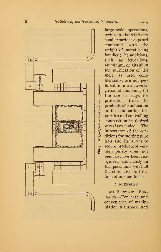
resistor. A furnace
of the kryptol type,
shown in Fig. 5, vras
constructed and has
been found satisfac-
tory. The A r s emvacuum fiu-nace,
shown in Fig. 6, wasextensively used and
is very suitable for
work of this char-
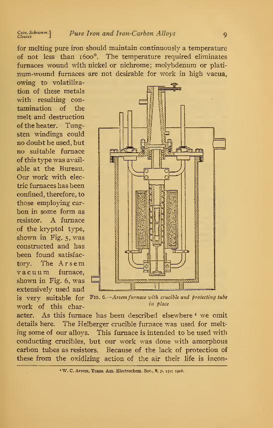
acter. As this furnace has been described elsewhere * we omit
details here. The Helberger crucible furnace was used for melt-
ing some of our alloys. This furnace is intended to be used with
conducting crucibles, but our work was done with amorphous
carbon tubes as resistors. Because of the lack of protection of
these from the oxidizing action of the air their life is incon-
FiG. 6.
—
Arsemfurnace with crucible and protecting tube
in place
*"W. C. Arsem, Trans. Am. Electrochem. Soc., 9, p. 152; 1906.
lO Bulletin of the Bureau of Standards [Vol. X3
veniently short. The resistance of Acheson graphite tubes wasfound to be too low to permit the desired temperatures to be
reached. There were difficulties in securing good electrical con-
tact between the terminals and the resistor so that this style of
furnace as used by us is not to be recommended for work at 1 600°
or above. The difficulty common to all the types of electric fur-
naces used (unless the precautions mentioned later were observed)
was that the melts were contaminated by volatile sulphur, silicon,
or carbon derived from the resistors used. This contamination
was least in the Arsem furnace when protecting the crucible, as
shown in Fig. 6, and was greatest in the Helberger furnace and in
the kryptol furnace when using amorphous carbon as resistors.
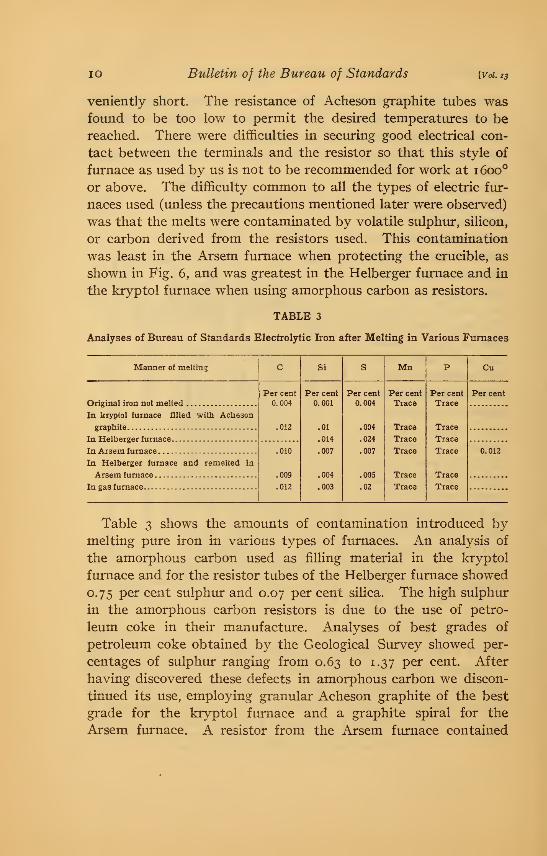
TABLE 3
Analyses of Bureau of Standards Electrolytic Iron after Melting in Various Furnaces
Manner of meltin:
Original iron not melted
In kryptol furnace filled with Acheson
graphite
In Helberger furnace
In Arsem furnace
In Helberger furnace and remelced ia
Arsem furnace
In gas furnace
jPer cent
0.004
,010
.009
.012
Si
Per cent
0.001
.01
.014
.007
.004
.003
Per cent
0.004
.004
.024
.007
.005
.02
Mn
Per cent
Trace
Trace
Trace
Trace
Trace
Trace
Per cent
Trace
Trace
Trace
Trace
Trace
Trace
Cu
Per cent
0.012
Table 3 shows the amounts of contamination introduced bymelting pure iron in various types of furnaces. An analysis of
the amorphous carbon used as filling material in the kryptol
furnace and for the resistor tubes of the Helberger furnace showed
0.75 per cent sulphur and 0.07 per cent silica. The high sulphur
in the amorphous carbon resistors is due to the use of petro-
leum coke in their manufacture. Analyses of best grades of
petroleum coke obtained by the Geological Survey showed per-
centages of sulphur ranging from 0.63 to 1.37 per cent. After
having discovered these defects in amorphous carbon we discon-
tinued its use, employing granular Acheson graphite of the best
grade for the kryptol furnace and a graphite spiral for the
Arsem furnace. A resistor from the Arsem fiunace contained

Cain, Sckramm,']Cleaves J
Pure Iron and Iro?i-Carbon Alloys II
0.02 per cent sulphur and 0.03 per cent silica. The results
were satisfactory. It may be concluded that if carbon resist-
ance furnaces are intended for making melts with minimumcontamination by volatile substances from the heating element,
the best material available at present is first-quality graphite;
and that the resistors should be carefully analyzed to insure
against impurity before installing them in the furnace. It is
further evident that if the refractory^ walls of the furnace are
in immediate contact with the heater, the former should be
made of material not likelv to react with the heated carbon.
Fig. 7
—
Small gas furnace uith preJieater
Such reaction would cause not only possible contamination of
the melt, but also irregularities in the working of the furnace.
For this reason ordinary fire clay or silica bricks, or any others
containing silica in considerable amount, are excluded. In our
own kryptol furnace commercial magnesite bricks were used, and
while they were not all that could be desired they proved service-
able, provided the resistor was renewed occasionally.
(6) Gas Furnaces.—Two types of gas furnace, shown in
Figs. 7 and 8, were used and no difficulty was experienced in
maintaining the necessarv' temperatures. The fiunace shown in
Fig. 7 was a standard type except in respect to the blowpipe,
which is similar to that used in tool forges, or for brazing purposes.
12 Bulletin of the Bureau of Standards [Vol. 13
A preheater raised the temperature of the necessary volume of
air to about 350°. In some experiments made with this furnace
pure platinum wire was melted, indicating that a temperature in
excess of 1750° had been attained. The refractory lining sup-
plied by the manufacturers was found to have a very short life
r/////y/^
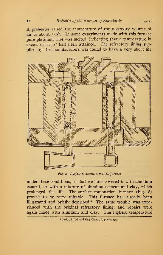
Fig. 8
—
Surface combustion cruciblefurnace
under these conditions, so that we later covered it with alundumcement, or with a mixture of alundum cement and clay, which
prolonged the life. The surface combustion furnace (Fig. 8)
proved to be very suitable. This furnace has already been
illustrated and briefly described.^ The same trouble was expe-
rienced with the original refractory lining, and repairs were
again made with alundum and clay. The highest temperature
^Lucke, J. Ind. and Eng. Chem., 5, p. 8oi; 1913.
Cain, Schramm.lCleaves J
Pure Iron and Iron-Carbon Alloys 13
reached in this furnace, 1670°, was obtained when burning about
180 cubic feet of city gas per hour. In using this type of furnace
for pure melts, the crucible must be protected from the large
amount of very fine dust blown out of the contact material during
operation.2. CRUCIBLES
A few preliminary experiments with clay crucibles showed that
it would be out of the question to use these for melting pure
iron-carbon alloys. The clays used for making the crucibles
which we tried were not sufficiently refractory and were badly
corroded by the iron oxide which coats the surface of all melts
made in gas-fired furnaces. This did not occur in the electric
furnaces, but here the reducing atmosphere, which prevented
oxidation, also caused the introduction of relatively large amounts
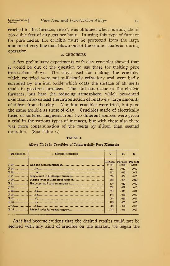
of silicon from the clay. Alundum crucibles were tried, but gave
the same trouble as those of clay. Crucibles made of electrically
fused or sintered magnesia from two different sotirces were given
a trial in the various types of fiunaces, but with these also there
was more contamination of the melts by silicon than seemed
desirable. (See Table 4.)
TABLE 4
Alloys Made in Crucibles of Commercially Pure Magnesia
Designation Method of melting c Si
Per cent Per cent
0.584 0.056
.022 .029
.367 .015
.886 .024
.688 .054
.210 .032
.252 .022
.094 .041
.146 .050
.088 .050
.765 .033
.058 .070
.927 .045
P27.
P28.
P29.
P41.
P39.
P31.
P32.
P33.
P35.
P37.
P40.
P42.
P36.
Gas and vacuum furnaces
do
do
Single melt in Helberger furnace..
.
Melted twice in Helberger furnace.
Helberger and vacuum furnaces
do
do
do
do
do
do
Melted twice in kryptol furnace
Per cent
0.004
.030
.029
.013
.026
.020
.010
.024
.029
.039
.015
.016
.019
As it had become evident that the desired results could not be
secured with any kind of crucible on the market, we began the
14 Bulletin of the Bureau of Standards [Vol. 13
experiment of making our crucibles of various grades of chemi-
cally pure magnesia calcined in the electric furnace at 1600° to
1800°. Although our product contained usually not over 0.05 to
o.io per cent silica the alloys melted in crucibles made from such
magnesia still carried too much silicon. (See Table 4.) Because
of the difficulty of securing from chemical dealers magnesia suffi-
ciently low in silica, the high cost of a good grade of this material,
and the need of large quantities for several contemplated inves-
tigations, we decided to prepare our own material. An endeavor
was made to develop a method free from too many complicated
manipulations. As raw^ material we used two or three grades of
pharmaceutical manesium carbonate carrying o.i or 0.2 per cent
silica, and later a calcined Grecian magnesite with about 3.5 per
cent silica. Attempts to prepare silica-free magnesia from these
sources by dissolving them in hydrochloric acid, evaporating the
solutions to dryness and baking, followed by solution of the
MgClj, filtration and precipitation of magnesium carbonate byammonium carbonate were not very successful on the scale tried,
for the technique was difficult and the product unsatisfactory, as
well as expensive.
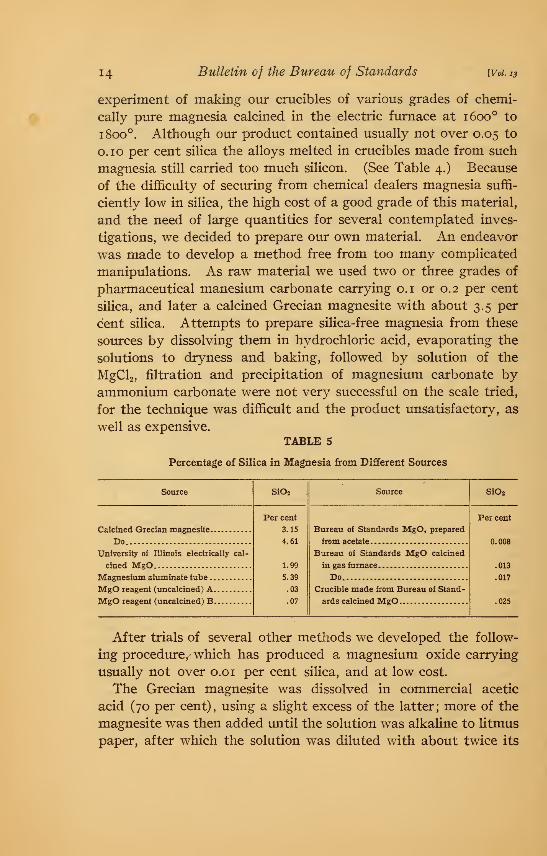
TABLE 5
Percentage of Silica in Magnesia from Different Soiirces
Source Si02 Source SiOa
Per cent
3.15
4.61
1.99
5.39
.03
.07
Bureau of Standards MgO, prepared
from acetate
Per cent
Do 008
University oi: Illinois electrically cal- Bureau of Standards MgO calcined
.013
IVIagnesium aluminate tube Do .017
Crucible made from Bureau of Stand-
ards calcined IVIgOjylgO reagent (uncalcined.) B 025
After trials of several other methods we developed the follow-
ing procedure, which has produced a magnesium oxide carrying
usually not over 0.0 1 per cent silica, and at low cost.
The Grecian magnesite was dissolved in commercial acetic
acid (70 per cent), using a slight excess of the latter; more of the
magnesite was then added until the solution was alkaline to litmus
paper, after which the solution was diluted v/ith about twice its
cimws^^^'^^^']Pure Iron and Iron-Carbon Alloys 15
volume of water, the whole thoroughly stirred and allowed to
stand in barrels for a day or two; at the end of this time the
clear solution was siphoned off into a large wrought-iron basin
and rapidly evaporated over a large Fletcher burner, adding
fresh liquid at intervals until a sufficient amount of the magne-
sium acetate had separated. The evaporation was then carried
to the point where the solution solidified on cooling, after which
the decomposition of the acetate into oxide was effected by direct-
ing the flame from a large Teclu burner over the surface of the
separated salts. The magnesium oxide so obtained is con-
taminated by carbon, undecomposed acetate, and a little iron,
but after calcining is quite suitable for use in making crucibles.
The calcining was done in large gas fiunaces which gave a tem-
perature of approximately 1550°. The magnesia, as taken from
the iron basin, was moislened slightly with water and madeup into large balls, which were placed inside an ordinary No. 20
plumbago crucible coated on the inside with alundum cement, or
lined with an Acheson graphite crucible. The crucible was
carefully covered during the calcining operation, which lasted
about two hours. As a result of this treatment the magnesia
had shrunk to about one-third its original volume, all the carbon
had burned out, and the silica content was very slightly increased.
We found it important to blow air through the furnace for several
minutes after shutting off the gas, in order to remove the last traces
of products of combustion carrying sulphur. If these are allowed
to remain in the furnace during the cooling period, the magnesia
takes up some sulphur; otu* best material contained less than
0.0 1 per cent of this element. Calcining in the gas furnace at
the temperature named gives a product which still shrinks a
little when used in crucibles heated to higher temperatures, but
we had no serious trouble with crucible failures on this account.
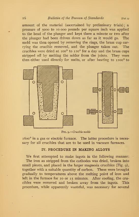
Two sizes of crucibles were used which, together with the molds
employed for making them, are shown in Fig. 9. The calcined
material was mixed with about 10 per cent by weight of uncal-
cined magnesia and the whole wet with water imtil it formed a
pasty mass. The thin brass cups used for lining the molds were
put in place and there was introduced into the mold a sufficient
41410°—16 2
i6 Bulletin of the Bureau of Standards [Vol. 13
amount of the material (ascertained by preliminary trials) ; a
pressure of 5000 to 10 000 pomids per square inch was applied
to the head of the plunger and kept there a minute or two after
the plunger had been driven down as far as it would go. Themold was then opened by removing the rings, the brass cup car-
rying the crucible removed, and the plunger taken out. Thecrucibles were dried at 100° to 120° for a day and the brass cups
stripped off by melting the solder from the joints. They were
then either used directly for melts, or after heating to 1200° to
Fig. 9.
—
Crucible molds
1600° in a gas or electric furnace. The latter procedure is neces-
sary for all crucibles that are to be used in vacuum furnaces.
IV. PROCEDURE IN MAKING ALLOYS
We first attempted to make ingots in the following manner:
The iron as stripped from the cathodes was dried, broken into
small pieces, and placed in the larger magnesia crucibles (Fig. 9),
together with a suitable quantity of carbon. These were brought
gradually to temperatures above the melting point of iron and
left in the furnace for 10 or 15 minutes. After cooling, the cru-
cibles were removed and broken away from the ingots. This
procedure, while apparently wasteful, was necessary for several
air^'c?^''^'^'"'"']Pure Iron and Iron-Carbon Alloys 17
reasons: (i) Magnesia crucibles are extremely fragile at
high temperatures and any attempt to handle them results in
breakage with resultant loss of nielts; (2) with the small mass of
metal which we used (100 g) it would be impossible to pour suc-
cessfully; and (3) even if it could be accomplished, pouring would
be objectionable because of the added danger of contamination.
Moreover, the loss of the crucible is not serious, since the m.aterial
can be recovered and worked up into new crucibles repeatedly.
The ingots obtained in the manner above described were found
to be very imsound and full of blowholes; in this respect there
was little difference between those made in the various furnaces.
This seemed surprising in view of the difference in atmosphere
over the melt in a gas furnace, where the conditions are oxidizing
to iron, and in an electric furnace, where carbon dioxide, water
vapor, or oxygen—the gases which would oxidize iron at high
temperatures—are present only in very small amounts. It
would thus appear that the blowholes in iron may be caused bycarbon monoxide as well as by any or all of the other gases named,
and that the maintenance of a reducing atmosphere is no guar-
antee of freedom from blowholes. That the melts made in the
kryptol furnace were made under reducing conditions is Evident
from Fig. 5, which shows that the crucibles are completely
covered with carbon at all times; this is further evident from an
oxygen determination made on drillings from an ingot melted
in the kryptol furnace. The percentage of oxygen in this ingot,
notwithstanding the fact that no deoxidizer had been used, was
0.03.^ The weight of these ingots was about 100 g. Fig. 10 (a)
is a photograph of a split ingot, showing the unsound structure.
The introduction of a regulated amount of carbon into the alloys
gave a good deal of trouble. In the gas furnace the amount of
oxidizing gases was so great, relative to the weight of carbon
introduced, that the latter was all btumed out before the melting
operation was completed, even when special precautions were
taken to protect the crucibles. These difficulties were finally
overcome by using the following procedure, which has been fairly
satisfactory: The electrolytic iron was first melted down in the
larger crucibles in a gas or electric fmnace. The ingots of pure
* We are indebted to J. A. Aupperle, metallurgist of the American Rolling Mill Co., for this analysis.
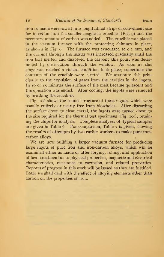
i8' Bulletin of the Bureau of Standards [Voi.13
iron so made were sawed into longitudinal strips of convenient size
for insertion into the smaller magnesia crucibles (Fig. 9) and the
necessary amount of carbon was added. The crucible was placed
in the vacuum furnace with the protecting chimney in place,
as shown in Fig. 6. The furnace was evacuated to 0.2 mm, and
the current through the heater was increased gradually until the
iron had melted and dissolved the carbon; this point was deter-
mined by obser^^ation through the window. As soon as this
stage was reached a violent ebullition took place; sometimes the
contents of the crucible were ejected. We attribute this prin-
cipally to the expulsion of gases from the cavities in the ingots.
In 10 or 15 minutes the surface of the melt became quiescent and
the operation was ended. After cooling, the ingots were removed
by breaking the crucibles.
Fig. 106 shows the sound structure of these ingots, which were
usually entirely or nearly free from blowholes. After discarding
the surface down to clean metal, the ingots were turned down to
the size required for the thermal test specimens (Fig. loc), retain-
ing the chips for analysis. Complete analyses of typical samples
are given in Table 6. For comparison. Table 7 is given, showing
the results of attempts by two earlier workers to make pure iron-
carbon alloys.
We are now building a larger vacuum fiunace for producing
large ingots of pure iron and iron-carbon alloys, which will be
examined either as made or after forging, rolling, and application
of heat treatment as to physical properties, magnetic and electrical
characteristics, resistance to corrosion, and related properties.
Reports of progress in this work will be issued as they are justified.
Later we shall deal with the effect of alloying elements other than
carbon on the properties of iron.
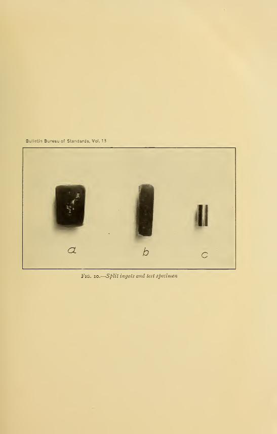
Bulletin Bureau of Standards, Vol. 13
Fig. io.—Split ingots and test specir

Cain, Sc'kramm.'lCleaves J
Pure Iron and Ircn-Carhon AJdoys
TABLE 6
Analyses of Typical Bureau of Standards Iron-Carbon Alloys
19
c Si s P Mn Cu Ni and Co Total Im-purities
Per cent Per cent Per cent Per cent Per cent Per cent Per cent Per cent
0.084 0.007 0.009 Trace Trace 0.020 a 0.011 0.047
.376 .013 .009 Trace Trace .005 a 0.11 .038
.395 .008 .013 Trace Trace .012 a. on .044
.597 .010 .008 Trace Trace .004 a. Oil .033
.624 .004 .010 Trace Trace .008 a. Oil .033
.692 .006 .011 Trace Trace .008 a. Oil .036
.860 .006 .006 Trace Trace .007 a. Oil .030
1.087 .006 .006 Trace Trace .013 a. Oil .036
1. 797 .010 .005 Trace Trace .018 a. Oil .044
2.240 .005 .005 Trace Trace .020 a. Oil .041
2.560 .005 .005 Trace Trace .014 a. Oil .035
3.27 .006 .006 Trace Trace .016 a. Oil .039
o The iSgures given for nickel and cobalt do not represent individual determinations for each specimen, since
the amoimt of sample was insufficient to allow of these being carried out. Four representative analyses onpureiron and iron-carbon alloys having given the result indicated, it was assumed that these elements were
present in that amount in all the samples.
TABLE 7
Degree of Contamination of Iron Melts Made by Others
Mn
Miiller's electrolytic iron
Miiller's electrolytic iron after remeltlng in vacuo in
"pure MgO crucible" a
C. F. Burgess' electrolytic iron
C. F. Burgess' electrolytic iron melted with sugar
carbon in magnesia crucible by Hov/e &
c Si P S
Per cent Per cent Per cent Per cent
0. 0630 0. 0053 C.0045 0.0024
.017 .089 .028 .037
.009 .006 <.001 .010
2.954 .040 .050 .035
Per cent
0. 0090
.025
Trace
None
a A. Miiller, Metallurgie, 6, p. 159; 1909.
6 Howe, Bull. Am. Inst. Min. Eng., p. 1118; 1913, No. i.
V. DISCUSSION OF THE SOURCES OF CONTAMINATION
1. SILICON
In our earlier experiments, where we were obliged to makecrucibles of magnesia higher in silica than that produced by the
acetate method already described, we noted that occasionally
an alloy of very low silicon content would result from a melt madein a crucible relatively high in silica. The use of our* purified

20 BMlleti7i of the Bureau of Standards [Vol. 13
magnesia had eliminated all trouble from silicon contamination
of melts, but we later decided to make some experiments to deter-
mine the relationship between the introduction of silicon and
temperature of melting. For this purpose a series of runs was'
made in the vacuum furnace varying independently the tem-
perature of melting and the silica content of crucibles. One per
cent of carbon v/as added to all these melts since in the presence
of carbon there is additional likelihood of contamination due to
reduction of silica at high temperatures. The results in Table 8
show that if the temperature is not allowed to rise m.uch above
1600°, crucibles containing as much as 0.9 per cent silica maybe used safely. This is of importance when a great deal of work
is being done, for it enables one to use repeatedly old crucible
material until the silica becomes dangerously high.
TABLE 8
Factors Governing Contamination of Melts by Silicon
Temperature of melting(degrees)
SiOa incrucible
Si inmelt
Temperature of melting(degrees)
SiOjincrucible
Si inmelt
1610
Per cent
0.57
.67
.75
.91
1.14
1.65
1.35
Per cent
0.007
.007
.007
.006
.015
.023
.032
1720
Per cent
1.27
1.20
.19
.24
.31
.60
Per cent
0.040
1510 1780 .042
1610 1770 .007
1610 1720 006
1610 1760 .021
1610 1740 . .031
1650
2. SULPHUR
As has been shown, contamination by sulphur may result
from the use of gas furnaces or of petroleum coke carbon in electric
furnaces. On abandoning the use of gas furnaces and employing
Acheson graphite as resistor material this difficulty disappeared,
as is apparent from a comparison of Tables 5 and 7.
3. MANGANESE AND PHOSPHORUS
Both these elements have been reduced to mere traces (less than
0.00 1 per cent) in all our alloys.
cZe^^^'^'^"'''""]Pure Iron and Iron-Carbon Alloys 2i
4. COPPER
This impurity, one of the most difficult to guard against, is
present in objectionable quantities in some of our melts and to
some extent in all. The ingot iron used for anodes contains copper
which is not completely removed in the electrolytic refining
process, so that our deposits contain about 0.005 P^i" cent of this
element. This Cu persists through the melting operation, and
imless great care is taken, more is introduced owing to the use
of copper connections in furnaces. In particular, the copper
blocks used in the vacuum furnace must be smooth and make good
contact with the graphite heater, since any arcing causes the vapor-
ization of considerable quantities of Cu with resulting contamina-
tion of the melt.
5. NICKEL AND COBALT
Our anode iron contains 0.02 per cent Ni + Co ; in the electrolytic
refining this is reduced to o.oi per cent which persists through the
melting operations.
6. MAGNESIUM
As all our melting was done in magnesia crucibles it was thought
desirable to look for this element as a possible impurity. Several
analyses of ingots made in the regular way showed that Mg wasnot present in any determinable quantity. A rather interesting
result, however, was obtained on analyzing some ingots which hadbeen melted at high temperatures (over 1700°). It was found
that these contained appreciable amounts of Mg (from 0.005 to
0.0 1 per cent). Furthermore, the samples were so brittle that
the pieces broke while turning in the lathe. It appears at least
possible that there may be a direct connection between the twocircumstances, though our present data are not sufficient to
justify a definite conclusion to that effect.
7. OXYGEN
Unforttmately, the Bureau is not at present prepared to makeaccurate oxygen determinations on this class of material, but it is
hoped later to publish analyses of some of the alloys for this
element, if it is found to be present. In our method of prepara-

22 Bulletin of the Bureau of Standards [Voi. 13
tion, starting with an ingot already low in oxygen (see p. 17) and
carburiling in a vacuum furnace where the carbon monoxide
resulting from interaction of oxides or oxygen with carbon would
be removed as formed, the deoxidation would tend toward com-
pletion, and accordingly the alloys should contain but small
residual amounts of oxides and oxygen.
VI. SPECTROSCOPIC EXAMINATION
In order to confirm the results of the chemical analyses for small
quantities of impurities, the arc spectra of a number of samples of
iron and iron-carbon alloys were studied by Dr. K. Burns ' of
this Biu-eau, to whom we are indebted for the data given below:
Magne^sium.—The spectra fully confirmed the chemical tests. Line 2851. i
A
showed strong in two samples containing 0.007 ^^^ o.oio per cent mg while it was
very faint or absent in tmfused irons and in alloys which failed to give magnesium
by the chemical method.
Silicon.—Line 2881.5A showed presence of silicon in the alloys, but tmfused iron
showed no traces.
Manganese.—Several manganese lines show in various samples of electrolytic
iron that have been melted. These lines are absent from the spectrum of immelted
electrolytic iron. The faintness of the manganese lines as compared with those given
by a specimen containing o.oi per cent of this metal indicate a very low manganese
content.
Chromium.—The statements made in regard to manganese also apply to chromium.
Copper.—Lines 3247.7 and 32 74.1A are always present though so faint as to be
questionable in unmelted specimens.
Nickel and Cobalt.—Several nickel and cobalt lines show faintly in the various
samples.
In the course of the examination of the arc spectrum of pure iron several faulty
identifications have been corrected
:
2795.542 ascribed to magnesium is iron;
3369.555 ascribed to nickel is iron and nickel;
3412.347 ascribed to iron is probably cobalt; and
3443.645 ascribed to iron is no doubt cobalt.
No attempt has as yet been made to clear up all the doubtful identifications in the
iron spectrum ; the above list is given to show the possibilities in this direction which
may be realized by means of the use of pure iron.
VII. METHODS OF CHEMICAL ANALYSIS
The analyses recorded in this paper were carried out according
to well-known principles with suitable precautions, and the methods
are given below merely for reference.
' For an account of the methods used, c. f. K. Burns, Bull. Bur. Standards, 12, pp. 179-196; 1916.

aJwe?^^'^'^'^"'']Pure Iron and Iron-Carbon Alloys 23
The chips obtained when making the thermal test specimens
were thoroughly mixed before weighing portions for analysis.
Chips from high-carbon alloys which contained admixed graphite
were finely ground and mixed before weighing.
1. CARBON
Carbon was determined by the barium-carbonate titration
method devised by one of the authors.^ The chips (i to 5 g) were
btimed in purified oxygen, passing the products of combustion
into a solution of barium hydroxide; the barium carbonate wasfiltered and washed in an atmosphere free from carbon dioxide
(see the original for details of apparatus used), and the barium
carbonate was titrated against standard hydrochloric acid, using
methyl orange as indicator.
2. SULPHUR
Sulphur was determined by dissolving 5 g of the metal, contained
in an appropriate evolution apparatus having all ground-glass
connections, in concentrated hydrochloric acid, the gases given off
being passed into an ammoniacal solution of hydrogen peroxide.
After complete solution of the metal the contents of the evolution
flask were boiled for 10 minutes while a slow current of purified
hydrogen was passed through the solution. The ammoniacal
peroxide solution was transferred to a beaker and boiled a few
minutes, then the solution was slightly ovemeutralized with
hydrochloric acid and the sulphur precipitated at boiling tem-
perature as barium sulphate. After digestion for a sufficient
length of time the precipitate was filtered, washed, ignited andweighed, and the percentage of sulphur calculated.
3. SILICON
Five to 10 g of metal were dissolved in an Erlenmeyer flask in
hydrochloric acid (equal volumes of water and hydrochloric acid
of specific gravity i .20) , the solution evaporated to dryness and the
flask heated on the hot plate at about 200° for an hotu". Theresidue was digested with hydrochloric acid of the same strength
as that used for dissolving, the insoluble matter containing the
8 J. R. Cain, Determination of Carbon in Steel and Iron by the Barium Carbonate Titration Method.
Bur. Stand. Technologic Paper No. 33.

24 Bulletin of the Bureau of Standards [Voi. 13
silica was filtered off, washed with dilute hydrochloric acid andwater, ignited in a platinum crucible and weighed, after which the
silica was volatilized with hydrofluoric acid and its amount deter-
mined from the change in weight of the crucible after again
igniting. The results were then calculated to silicon.
4. PHOSPHORUS
The usual method of precipitation as ammonium phosphomolyb-
date was employed, and the phosphorus estimated by comparing
the volume of the precipitate with that produced by treating a
standard steel in the same way.
5. MANGANESE
The sodium bismuthate method was used.
6. COPPER
Ten to 20 g of metal were dissolved in a slight excess of hydro-
chloric or sulphuric acid, and hydrogen sulphide passed into the
hot solution until all the copper was precipitated. The precipi-
tate was filtered off, and, after washing the paper carrying it, was
transferred to a porcelain crucible, and the whole ignited until all
the carbon was burned off. A little potassium bisulphate was
added and the copper oxide brought into solution by fusion,
following by leaching with water and filtration. The solution
was compared with a standard solution colorimetrically, either
by the ammonia or ferrocyanide method, or by both.
7. MAGNESIUM
Ten to 20 g of metal were dissolved in aqua regia, the solution
evaporated to dryness, and dehydrated. The residue was dis-
solved in 1:1 HCl and silica removed by filtration. The iron was
extracted by the ether method. After the removal of the iron,
hydrogen sulphide was passed through the solution (acidified with
acetic acid) to precipitate copper, etc. Manganese and residual
i^ron were removed from the filtrate by bromine and ammonia and
the magnesium was precipitated as magnesium-ammonium phos-
phate. The accuracy of the above procedure was checked byrunning duplicates to which small amounts of a magnesium salt
had been added.
cteave^'^^^^^^']Puve Iyou and Iron-Carbon Alloys 25
8. NICKEL AND COBALT
The solution of 10 g in HNO3 + HCI was evaporated to dryness,
dehydrated, taken up with HCl of i.i specific gravity, filtered,
the filtrate evaporated to a small volume, and the iron removed
by the ether method. Copper was precipitated with hydrogen
sulphide, and the iron and manganese in the filtrate were pre-
cipitated by ammonia and bromine. The filtrate was acidified
with acetic acid, and nickel and cobalt were precipitated as sul-
phides from the boiling solution. The two metals were either
weighed as oxides or deposited electrolytically from ammoniacal
solution, the two methods giving concordant results. The oxides
(or metals) were dissolved in hydrochloric acid, the solution wasneutralized, and finally made acid with acetic acid and the cobalt
precipitated as K3Co(N02)6. After filtering and igniting this pre-
cipitate at a low temperature, the cobalt was dissolved, repre-
cipitated with hydrogen sulphide, and finally weighed as C0SO4.
The nickel was determined by the dimethylglyoxime method in
the filtrate from the cobalt. The sum of these determinations
checked very closely with the total nickel -1- cobalt found directly.
VIII. SUMMARY
Methods have been developed for producing laboratory samples
of iron-carbon alloys, of a very high degree of purity; sources of
contamination of melts and means of eliminating them have been
described; a method for producing magnesia of a satisfactory
degree of purity for making crucibles to be used in work of this
kind has been developed; a procedure for making small ingots,
which are sound and free from blowholes, without the use of deoxi-
dizers has been worked out. A series of iron-carbon alloys con-
taining 99.96 per cent of the two elements has been prepared, to
serve as a basis for the redetermination of the iron-carbon equi-
librium diagram.
Washington, November 11, 191 5.
BIBLIOGRAPHY
PREPARATION OF ELECTROLYTIC IRON
LBnz, J. f. prakt. Chem., 108, p. 438; 1869.
CaiIvLKTET, Comptes Rendus, 80, p. 319; 1875.
Roberts-Austen, J. Iron and Steel Inst., 1, p. 71; 1887.
Arnold and Hadb'ield, Stahl u. Eisen, p. 526; 1894.
Hicks and O'Shea, Electrician, p. 843; 1895.
Winterer, Z. f. Elektrochem., 4, p. 338; 1898.
Haber, Z. f. Elektrochem., 4, p. 410; 1898.
Abegg, Stahl u. Eisen, p. 736; 1901 (II).
Skrabal, Z. f. Elektrochem., 10, p. 749; 1904.
C. F. Burgess and Hambuechen, Trans. Amer. Electrochem. Soc. 5, p. 201; 1904.
Maximowitsch, Z. f. Elektrochem., 11, p. 52; 1905.
Ryss and Bogomolny, Z. f. Elektrochem., 12, p. 697; 1906.
CowPER-Cowi.ES, C. A., 3, p. 1371; 5, p. 3013; 8, p. 3648.
C. F. Burgess and Watts, Trans. Amer. Electrochem. Soc, 9, p. 229; 1906.
Amberg, Z. f. Elektrochem., 14, p. 326; 1908.
Kern, Trans, Amer. Electrochem. Soc, 3, p. 103; 1908.
MuLiyER, Metallurgie, 6, p. 145; 1909 (contains bibliography).
Pfaff, Z. f. Elektrochem., 16, p. 217; 1910.
Tucker and Schramm, J. Ind. and Eng. Chem., 2, p. 237; 1910.
Watts and Li, Trans. Amer. Electrochem. Soc, 25, p. 529; 1914.
Yensen, University of Illinois Bulletin No. 72, 1914.
26