premises pager system - infinity pos · premises pager system ... should be centrally located...
TRANSCRIPT

PREMISES PAGER SYSTEM®
UHF Desktop Transmitters
GuestAlert® 200 Series PeopleAlert™ 2600 PeopleAlert™ 2601 with Telephone Interconnect
Installation and Operation Guide Part Number 320115 Rev M
April 2005


Introduction
JTECH Communications Inc., a subsidiary
of MICROS Systems Inc., designs and manufactures cost effective in-house
communications systems for customers throughout the world.
Thank you for choosing JTECH Communications Inc. as the provider for your on-premises paging requirements. We truly appreciate your confidence in our products. At JTECH there is no greater commitment than providing you with total customer satisfaction. Please take a few minutes to review this manual prior to installing and operating your system. The manual will provide you with installation instructions, provide answers to the most frequently asked questions, and offer suggestions to ensure you receive all of the many benefits your system can provide. Additionally, this manual will assist you with problem determination and offer helpful advice when seeking customer service. We are confident that JTECH Communications Inc. has the most responsive customer service available within the industry. Please do not hesitate to call JTECH Communications Inc. Customer Care at 800.321.6221, Option 6, if you have any questions. We look forward to a long and mutually rewarding partnership.

Table of Contents
OVERVIEW...................................................................................................................................................1
INSTALLATION............................................................................................................................................2 INSTALLING THE TRANSMITTER .....................................................................................................................2 PAGERS ......................................................................................................................................................4 RANGE TEST ...............................................................................................................................................5
USING THE RECHARGEABLE VIBRATION PAGERS..............................................................................6
USING THE INSTACALL™ VIBRATION PAGERS...................................................................................11
USING THE INSTACALL™ NUMERIC PAGERS......................................................................................12
USING THE GLOWSTER® PAGERS ........................................................................................................14
USING THE COMMPASS™ PAGER..........................................................................................................20 PAGER OPERATION....................................................................................................................................21 COMMPASS CHARGER ...............................................................................................................................21 COMMPASS PAGER CHARGE INDICATOR.....................................................................................................22 SEARCH ....................................................................................................................................................23 VOICE ALERTS...........................................................................................................................................23
PAGING FROM THE DESKTOP TRANSMITTER.....................................................................................27
PAGING USING THE TELEPHONE INTERCONNECT ............................................................................28
PROGRAMMING YOUR APPLICATION TO COMMUNICATE VIA RS232 .............................................29
APPENDIX A – TRANSMITTER FUNCTION MENU.................................................................................34
APPENDIX B – TECHNICAL INFORMATION...........................................................................................39
APPENDIX C – TRANSMITTER POWER ADJUSTMENT........................................................................40
APPENDIX D – TELEPHONE INTERCONNECT SPECIFICATIONS.......................................................41
APPENDIX E – DETAILED TECHNICAL SPECIFICATIONS...................................................................43
SERVICE.....................................................................................................................................................45
GENERAL TERMS AND CONDITIONS ....................................................................................................46

JTECH UHF Desktop Transmitter Installation and Operation Guide 320115M Page 1
Overview Congratulations on your purchase of JTECH Communication’s state of the art GuestAlert® or PeopleAlert™ Desktop Paging System. Using the Desktop Transmitter you can easily page site mobile employees or customers with vibration/tone, numeric pagers, the popular Glowster® vibe/flash pagers and the new CommPass™ family of Vibe, Tone, Flash and Voice pagers. If so equipped, pages can also be sent using the PeopleAlert Telephone Interconnect option or HostAlert® via an RS-232 serial connection. A numeric message of up to sixteen digits can be sent to a single numeric pager or a group of numeric pagers. Vibration/tone pagers can be paged individually or in groups, and Glowster and CommPass family pagers can be paged individually or all together using the special ‘All Call’ feature. The paging system can support up to 9,950 total pagers and is designed to support a paging area of one to two miles. Each individual installation location will have its own characteristics that will affect coverage. The GuestAlert 200 Series, PeopleAlert 2600 and PeopleAlert 2601 with Telephone Interconnect systems are FCC licensed products.
Components The basic system components are: • Desktop Master Transmitter Unit
− GuestAlert 200 Series Transmitter with power adapter and antenna − PeopleAlert Transmitter with power adapter and antenna
(**Optional Call4Sure™ cellular phone paging module available on the GuestAlert 200 Series and PeopleAlert 2600 model transmitters)
− PeopleAlert Telephone Interconnect Transmitter with cable, power adapter and antenna
• Magnetic Transmitter Function Guide • Vibration/Tone, Numeric, Glowster or CommPass pagers • Warranty Registration Card • Installation and Operation Guide ** Note: Call4Sure product documentation is shipped only when this option is purchased.
Two optional range extending options are available to meet special needs: • Magnetic Mount Antenna • Extended Range Option Please inspect the system upon receipt. If the contents appear to be damaged immediately contact the shipper to file a claim and notify JTECH Customer Care. If any components are missing, contact a JTECH Customer Care Representative at 1.800.321.6221, Option 6.
JTECH UHF Desktop Transmitter Installation and Operation Guide 320115M Page 2
Installation
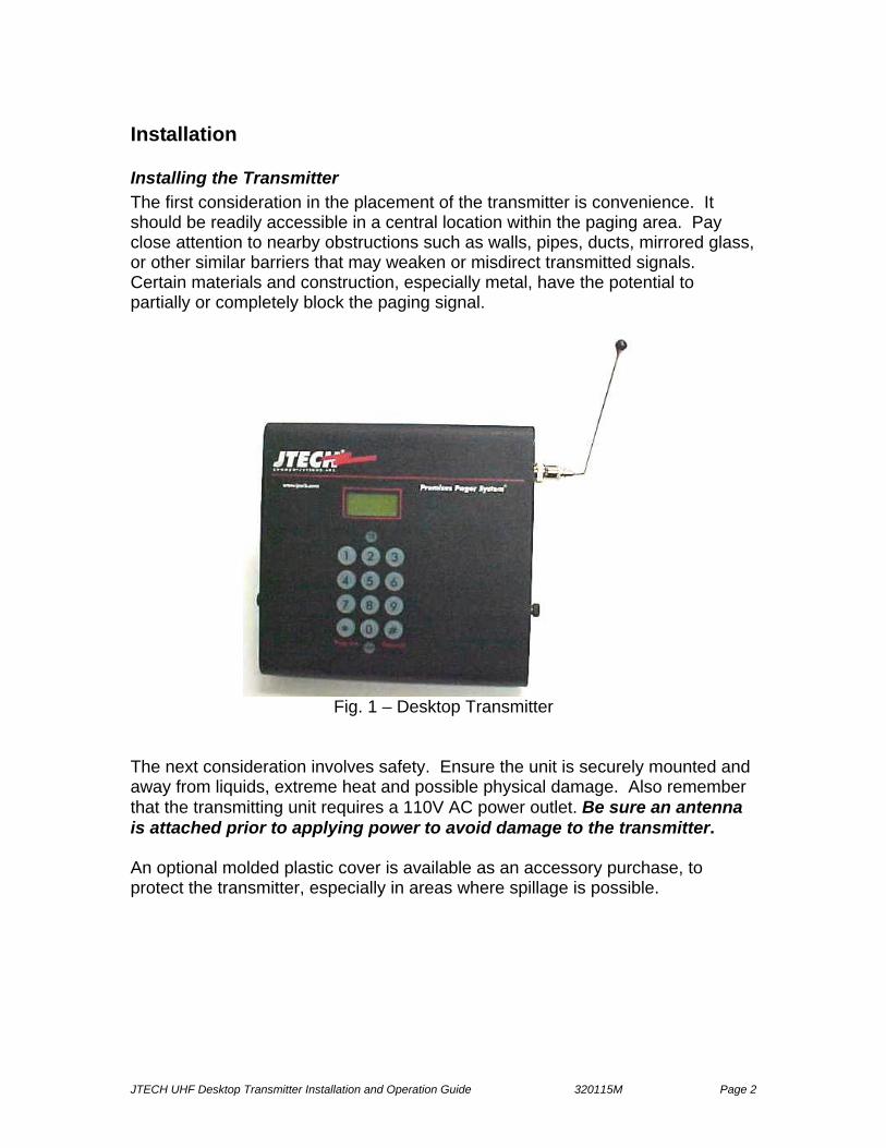
Installing the Transmitter The first consideration in the placement of the transmitter is convenience. It should be readily accessible in a central location within the paging area. Pay close attention to nearby obstructions such as walls, pipes, ducts, mirrored glass, or other similar barriers that may weaken or misdirect transmitted signals. Certain materials and construction, especially metal, have the potential to partially or completely block the paging signal.
Fig. 1 – Desktop Transmitter
The next consideration involves safety. Ensure the unit is securely mounted and away from liquids, extreme heat and possible physical damage. Also remember that the transmitting unit requires a 110V AC power outlet. Be sure an antenna is attached prior to applying power to avoid damage to the transmitter. An optional molded plastic cover is available as an accessory purchase, to protect the transmitter, especially in areas where spillage is possible.

JTECH UHF Desktop Transmitter Installation and Operation Guide 320115M Page 3
The transmitter can be mounted in one of two ways: 1) placed on a flat surface such as a counter or desktop with the attached stand, or 2) mounted to a wall using the attached stand as a mounting plate. Four holes are provided to facilitate wall mounting. The four #6 screws are user provided and can be purchased from a local hardware store. When placed on a flat surface the angle of the unit may be adjusted using the thumbscrews on either side of the unit. For best results, the transmitter antenna must be vertical. Ideally the transmitter should be centrally located within the area where paging is to occur. Since this is not always possible, range testing at different locations may be required to obtain the desired performance. See the special function section of this guide entitled ‘Range Test’ for more information. Also consult your Sales Consultant for additional information. Once the Desktop Transmitter and antenna have been installed, plug in the power adapter. Once powered the transmitter will display ‘Enter Pager #’’ indicating it is ready to send a page. The red power light (PWR) will be lit. PeopleAlert 2601 Telephone Interconnect Transmitter Connection Connect one end of the RJ-11 phone cord to the phone jack on the side of the unit and the other to an available phone line jack in your telephone system. The Telephone Interconnect requires a dedicated analog phone line and the Telephone Interconnect must be able to hear the tones from a push button telephone. Please refer to the section entitled ‘Telephone Interconnect Specifications’ for additional help in determining the type of phone line. Optional Magnetic Mount Antenna The optional Magnetic Mount Antenna with its 12-foot extension cable should be mounted vertically and as high as possible. Its base is magnetized for mounting convenience but does not have to be attached to a metal surface. If the Magnetic Mount Antenna is not attached to a metal surface, please ensure that it is secured in some way. This antenna is designed for indoor use only. Optional Extended Range The Extended Range Options include:
1) A 6’ antenna and cable, which will boost signal by approximately 15%. 2) An indoor/outdoor antenna, a 50-foot cable, 35-watt power amplifier and
power supply. This option increases the power output of the transmitter to from 2 watts to 35 watts, and increases range to up to 5 miles in open areas. Installation of this antenna and power amplifier requires special skills. Consult your JTECH Sales Representative for additional information. This option is not available in certain countries.
Because implementation of Extended Range Options boosts transmitter power (ERP) output above 2 watts, these options require FCC Approval and Licensing. Your JTECH sales manager can assist in securing appropriate FCC licensing.
JTECH UHF Desktop Transmitter Installation and Operation Guide 320115M Page 4
Transmitter Function Menu The Desktop Transmitter functions are accessible from a function menu that is accessed by pressing the * key. In an effort to reduce potential system problems due to erroneous changes in system settings, most of this menu is password protected. The factory default password is “1234.” Most commonly used transmitter functions are also available via 4-digit code access, codes which are supplied on the magnetic guide that is shipped with your transmitter. A detailed review of these functions appears in the appendix of this manual.
Pagers The GuestAlert and PeopleAlert systems support InstaCall vibration/tone pagers, InstaCall Numeric pagers, ServerPass, PeoplePass and ParentPass pagers, the popular Glowster vibe/flash pagers and the distinctive new CommPass pagers. Your pagers were programmed by JTECH to meet your requirements as confirmed with your Account Sales Executive or Corporate Sales Representative. Vibe/Tone Pagers There are a number of optional programming modes available with the InstaCall™ vibe/tone pagers. The pager is programmed with one primary ID number and there are options to also program that same pager to support up to three groups (group ID’s 1-9.) The option to enable the InstaCall vibe/tone pager to support groups ID’s pre-programmed from the factory allows all pagers identified within these groups to be alerted with a single transmission. The possible pager numbers are 1 - 9950. To page all vibe/tone pagers at once (All Call feature), enter “9998#”on the keyboard or the phone. InstaCall vibe/ tone pagers support over-the-air shut down, which turns off all pagers. This feature is accessible by entering “9991#” from the keyboard or the phone. InstaCall Vibe/Tone pagers can also be shut off individually by depressing and holding the ‘ON’ button for 5 seconds. Numeric Pager Numeric pagers can have four ID’s each. The first is used as its unique ID for single pager paging or as a member of a dynamic group while the second, third, and fourth ID may be used to enable factory programmed group paging. For example, pagers 1-20 could be programmed with numbers 1-20 as their first ID. Pagers 1-10 could also be programmed with ‘factory programmed GROUP 2’ as their second ID; pagers 11-20 could be programmed with ‘factory programmed GROUP 3’ as their second ID. This would allow pagers 1-10 to be ‘factory programmed group paged’ when “*2#” or “*2*5678#” is entered on the GuestAlert keypad or the PeopleAlert keypad or phone, and pagers 11-20 to be factory programmed group paged when “*3#” or “*3*5678#” is entered. InstaCall Numeric pagers can be shut off individually by scrolling through the menu functions using the bottom button, selecting “Pager Off” using the middle button when the text is displayed in the LCD screen. When in the off position, the pager LCD screen will display “Off” along with the time and date.

JTECH UHF Desktop Transmitter Installation and Operation Guide 320115M Page 5
Glowster Vibe/Flash and CommPass Pagers The Glowster and CommPass vibe/flash pagers can be programmed with one primary ID number, which can be used for single pager paging. Glowsters and CommPass Pagers also respond to the All Call feature.
Range Test A range test verifies the paging coverage area. Press the * key to get to Range test screen selecting this option with the # key, or simply enter 9990# from the keyboard or phone. The Range Test feature sends a Range Test page about every 5-6 seconds to all pagers that have been placed in Group #99. (The factory default pager ID is #1. See Dynamic Group related instructions in this guide under transmitter operations for detailed information the dynamic group feature.) Range testing is performed by carrying that pager slowly to the place where the periodic page cannot be received this establishes the range for transmission. Press any key on the transmitter keypad to exit Range Test mode. NOTE: If the Out-of-Range feature is to be used, range testing is required in order to most accurately set the transmitter power level. For more information, please refer to the Transmission Power Adjustment section of this Guide. Group Paging The Desktop Transmitter supports group paging. There are two types of groups: • Hardware groups (1-9) are pre-preprogrammed at the factory and call
InstaCall and PeoplePass pagers identified within the group with a single transmission
• Dynamic groups (1-99; max 10-12 pagers per group) are user-programmable and call pagers within the groups successively vs. via a single transmission
Groups are not available with Glowster or CommPass pagers, as these pagers are not typically used for staff paging where group paging is most used. Additional details on group paging appear in the transmitter feature section of this guide or contact your JTECH Account Executive or JTECH Customer Care.

JTECH UHF Desktop Transmitter Installation and Operation Guide 320115M Page 6
Using the Rechargeable Vibration Pagers The ServerPass rechargeable UHF pager is a durable paging solution designed to meet the rigorous requirements of the typical restaurant environment, as well as other business applications. Part of JTECH’s 200 Series paging solutions, this robust pager platform can also be configured with accessories and programming for guest, customer and other people queuing applications. It is available in various combinations of vibration (vibe), tone and flash alerts. ServerPass includes a durable low-profile belt clip. A swivel belt clip or advertisement paddle is standard on all other models. NOTE: A special version of this product known as ParentPass is specifically configured for the needs of the Church Nursery environment. The ServerPass/ParentPass charging rack accommodates 10 pagers with belt clip or promoback, and is designed for desktop or wall mounting.
Fig. 5 – ServerPass/ParentPass Charger
Charger power indicator light
Fig. 2 – ServerPass Pager with low-profile belt clip
Pager power indicator light and pager ID #
Fig. 3 – Pager with Promoback Pager power
indicator light and pager ID #
Fig. 4 – ParentPass Pager
JTECH UHF Desktop Transmitter Installation and Operation Guide 320115M Page 7
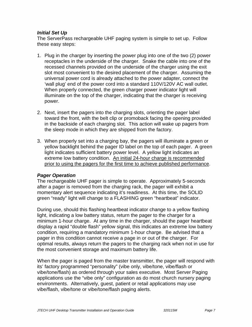
Initial Set Up The ServerPass rechargeable UHF paging system is simple to set up. Follow these easy steps: 1. Plug in the charger by inserting the power plug into one of the two (2) power
receptacles in the underside of the charger. Snake the cable into one of the recessed channels provided on the underside of the charger using the exit slot most convenient to the desired placement of the charger. Assuming the universal power cord is already attached to the power adapter, connect the ‘wall plug’ end of the power cord into a standard 110V/120V AC wall outlet. When properly connected, the green charger power indicator light will illuminate on the top of the charger, indicating that the charger is receiving power.
2. Next, insert the pagers into the charging slots, orienting the pager label
toward the front, with the belt clip or promoback facing the opening provided in the backside of each charging slot. This action will wake up pagers from the sleep mode in which they are shipped from the factory.
3. When properly set into a charging bay, the pagers will illuminate a green or
yellow backlight behind the pager ID label on the top of each pager. A green light indicates sufficient battery power level. A yellow light indicates an extreme low battery condition. An initial 24-hour charge is recommended prior to using the pagers for the first time to achieve published performance.
Pager Operation The rechargeable UHF pager is simple to operate. Approximately 5-seconds after a pager is removed from the charging rack, the pager will exhibit a momentary alert sequence indicating it’s readiness. At this time, the SOLID green “ready” light will change to a FLASHING green “heartbeat” indicator. During use, should this flashing heartbeat indicator change to a yellow flashing light, indicating a low battery status, return the pager to the charger for a minimum 1-hour charge. At any time in the charger, should the pager heartbeat display a rapid “double flash” yellow signal, this indicates an extreme low battery condition, requiring a mandatory minimum 1-hour charge. Be advised that a pager in this condition cannot receive a page in or out of the charger. For optimal results, always return the pagers to the charging rack when not in use for the most convenient storage and maximum battery life. When the pager is paged from the master transmitter, the pager will respond with its’ factory programmed “personality” (vibe only, vibe/tone, vibe/flash or vibe/tone/flash) as ordered through your sales executive. Most Server Paging applications use the “vibe only” configuration as do most church nursery paging environments. Alternatively, guest, patient or retail applications may use vibe/flash, vibe/tone or vibe/tone/flash paging alerts.

JTECH UHF Desktop Transmitter Installation and Operation Guide 320115M Page 8
Receiving Pages When a page is transmitted and received after charging the Pager for the recommended time period, the rechargeable UHF pager will alert depending on how it has been ordered and subsequently programmed: SERVER PROGRAMMING: • Vibe/Tone pager: 2 seconds of VIBRATION, TONE or VIBE and TONE
cadence, depending on which product was ordered GUEST PROGRAMMING: • Vibe and Flash pager: 1.5 seconds alternating VIBRATION and FLASH
followed by 13.5 seconds synchronous flashing of the 4 LED’s • Same as above preceded by 6 brief tones Battery Installation The rechargeable nickel metal hydride (NiMH) battery pack will typically last from one to three years depending on usage. To replace the battery pack, first remove the battery door screw from the rear of the pager using a small Phillips head screwdriver. Slide the battery door down from the top to open. Place the door and set screw in a safe place for closure after changing the rechargeable battery pack. Carefully remove the old battery pack, disconnecting the plastic connector from the port inside the pager. Plug in the replacement battery pack (JTECH part number 232020.) To re-insert the replacement battery pack:
1) Feed the battery cable into the open area inside the pager housing to the right of the port.
2) Place the battery into the available space by inserting the long side (with the battery cable connector) into the space, rolling the other side of the battery “down” into the housing.
3) Replace the battery door and re-secure it into place using the Phillips head set screw.
Clip or Promoback Replacement To replace a damaged low-profile clip or promoback, follow the instructions above to remove the battery door. With the door removed, remove the damaged low-profile clip, rotary knob (for the swivel clip) or promoback. Replace with the appropriate replacement part available for purchase as an accessory from JTECH Communications. Replace and re-secure the battery door.
Fig.6 – Battery Installation
Battery Door Screw

JTECH UHF Desktop Transmitter Installation and Operation Guide 320115M Page 9
Connecting Two Chargers Caution: If chargers are connected to the power adaptor, disconnect the power adaptor from the chargers BEFORE performing this operation. When connecting two chargers, first extend the stored connector plates on the underside “rear” of the unit. (A small flat-tipped screwdriver is recommended for use to initially slide out the connector tabs for accessibility.) Once accessible, pull each of the two connector plates out until they “snap and lock” in the extended position. Push firmly inward on the extended connector plates to ensure they are in the locked in the extended position. Insert the extended connector plates into the female receptacles on the “front” of the adjoining unit, pushing the units together until the connector plates “snap and lock” into place in the adjoining unit. The two units should be firmly connected flush to each other at this time. Using the included “pigtail” connector, connect the first unit to the second unit, inserting the cable wire into the recesses provided in the underside of the housing, ensuring the cable is under all of the retaining tabs provided. Up to two (2) charging units may be connected together on the same standard JTECH power adapter, supporting up to 20 pagers from a single power adapter. Care and Maintenance Wipe with a soft cloth moistened with mild soap and water. Never spray liquids (cleaning solution or water) directly on the pagers or the charger.
Fig. 7 – Extending Connector Plates on the Charger
Fig. 8 – Connecting Chargers Fig. 9 – “Pigtail” Power Connector

JTECH UHF Desktop Transmitter Installation and Operation Guide 320115M Page 10
Special Functions To page the ServerPass pager pre-programmed with a ServAlert system from a GuestAlert transmitter, from the master transmitter keypad, type 9xxx# (where x represents the pager ID; in instances where the pager ID number is less than 3-digits the leading x is replaced with a zero (0)) The pager will respond with a unique pulsating cadence, alerting the server that they are needed at the hostess stand or reception desk. To page the Rechargeable UHF Pager pre-programmed with the multiple vibration (Multi-Vibe) option from the GuestAlert/PeopleAlert master transmitter keypad, type
1 vibration = 1xxx# 2 vibration = 2xxx# 3 vibration = 3xxx#
(where x represents the pager ID; in instances where the pager ID number is less than 3-digits the leading x is replaced with a zero (0)) Example: Send 2 vibe alert to pager id 1 = 2001# Send 3 vibe alert to pager id 2 = 3002# Send 2 vibe alert to pager id 12 = 2012# Send 3 vibe alert to pager id 224 = 3224# To page a rechargeable UHF pager from the telephone interface on the PeopleAlert 2601, pick up the receiver, listen for the dial tone, and dial the system extension or analog phone line number that has been assigned to the Paging System. The line will ring until the unit answers, at which point the Out-of-Range (OOR) signaling is temporarily de-activated. 1. When connected (a beep indicates the system is ready for you to enter the pager number) press the number of the pager (up to four digits) you wish to page, using the telephone keypad, and press the # key to send the vibration/tone page. The same option to page with multiple vibrations is available from the telephone interface by dialing into the assigned extension and following the instructions noted above.
JTECH UHF Desktop Transmitter Installation and Operation Guide 320115M Page 11
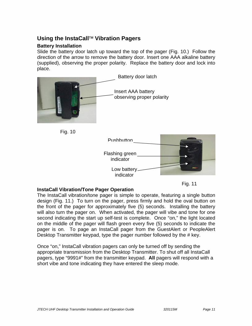
Using the InstaCall™ Vibration Pagers Battery Installation Slide the battery door latch up toward the top of the pager (Fig. 10.) Follow the direction of the arrow to remove the battery door. Insert one AAA alkaline battery (supplied), observing the proper polarity. Replace the battery door and lock into place.
Fig. 10
Fig. 11 InstaCall Vibration/Tone Pager Operation The InstaCall vibration/tone pager is simple to operate, featuring a single button design (Fig. 11.) To turn on the pager, press firmly and hold the oval button on the front of the pager for approximately five (5) seconds. Installing the battery will also turn the pager on. When activated, the pager will vibe and tone for one second indicating the start up self-test is complete. Once “on,” the light located on the middle of the pager will flash green every five (5) seconds to indicate the pager is on. To page an InstaCall pager from the GuestAlert or PeopleAlert Desktop Transmitter keypad, type the pager number followed by the # key. Once “on,” InstaCall vibration pagers can only be turned off by sending the appropriate transmission from the Desktop Transmitter. To shut off all InstaCall pagers, type “9991#” from the transmitter keypad. All pagers will respond with a short vibe and tone indicating they have entered the sleep mode.
Battery door latch
Insert AAA battery observing proper polarity
Pushbutton
Flashing green indicator
Low battery indicator

JTECH UHF Desktop Transmitter Installation and Operation Guide 320115M Page 12
Low Battery Indicator The light located on the bottom of the InstaCall pager will flash red indicating the battery is low. If the top green light flashes every five seconds, the battery is OK. If no light is present, the battery is dead and needs to be replaced. Receiving Pages When a page is received, the InstaCall pager will alert depending on how it has been programmed: • Vibe only pager: 4 vibrations lasting 4 seconds with a flashing green indicator
light • Tone only pager: 4 tones lasting 4 seconds with a flashing green indicator
light • Vibe and tone pager: 4 vibration and tone alerts lasting 4 seconds with a
flashing green indicator light Press the oval button on the front of the pager to stop the alert or wait until the alert stops by itself. The pager is now ready to receive the next page. Note for legacy installations: The InstaCall Pager does not support the Server paging “VSERV” programming and “Multi-Vibe” features used in specialized markets. These features are supported by the Rechargeable UHF pages. Care and Maintenance Wipe with a soft cloth moistened with mild soap and water. Never spray liquids (cleaning solution or water) directly on the pagers.
Using the InstaCall™ Numeric Pagers The InstaCall Numeric pager option is primarily used to provide specific numeric information or codes to individual recipients or groups of individuals. The pager features a back-lit top-mount LCD display panel and message control buttons on the face instead of indicator lights. The InstaCall Numeric pager displays date and time, as well as a low battery icon. It can store up to 16 messages with message lock and individual message delete and delete all functionality. Please refer to the pocket User Manual enclosed with each InstaCall Numeric pager for detailed operational instructions.
Using the InstaCall™ Alphanumeric Pagers
The InstaCall Alphanumeric pager option is primarily used in conjunction with the RS-232 data-feed option to provide specific alphanumeric (text) information to individual recipients or groups of individuals. This 4-line pager features a back-lit front-mount LCD display panel with message control buttons on the face and can store up to

JTECH UHF Desktop Transmitter Installation and Operation Guide 320115M Page 13
25,000 characters (100+ messages.) Please refer to the pocket User Manuals included with your system shipment for detailed operational instructions.

JTECH UHF Desktop Transmitter Installation and Operation Guide 320115M Page 14
Using the Glowster® Pagers Battery Installation The Glowster and Patient Pager products are powered by a user-replaceable rechargeable Nickel-Metal Hydride (NiMH) battery pack. To replace the battery pack, remove the battery door screw and battery door located on the rear of the pager (Fig. 12). Remove the existing battery pack and place a new pack into the battery compartment. (For your convenience, JTECH offers a replacement battery pack; order with part number 232020.) Once battery pack is installed, replace the battery door and reinstall the screw. After installing the replacement battery pack, the heartbeat indicator should be visible.
Fig. 12 – Glowster Pager Top and Bottom Glowster Heartbeat/Charge Indicator Under normal operations, Glowsters display a solid red ‘ready’ light when on the charging rack. Immediately after removing a Glowster from the charging rack, this ‘ready’ light will go out and, after 3 seconds, a short vibe/flash ‘test page’ will occur, alerting the operator that the Glowster is ready for use. When off the charging rack and operating normally, the ‘ready’ light LED will flash as a 'heartbeat' indicator every two seconds to indicate proper operation. When placed on the charging rack in a low battery state, the ‘ready’ light will display a rapid ‘double flash,’ indicating that the unit has entered the cautionary 1-hour mandatory minimum charge routine. After 1-hour, the low-battery ‘double flash’ indicator will be replaced by the solid red ‘ready’ light. For optimal performance, Glowster pagers should charge for an eight (8) to twelve (12) hours to become completely recharged. When off the charger, if the Glowster detects insufficient battery power, the heartbeat indicator will stop, and the unit will enter a sleep state until placed back on the charger, where it will enter the 1-hour mandatory charge routine.
JTECH UHF Desktop Transmitter Installation and Operation Guide 320115M Page 15
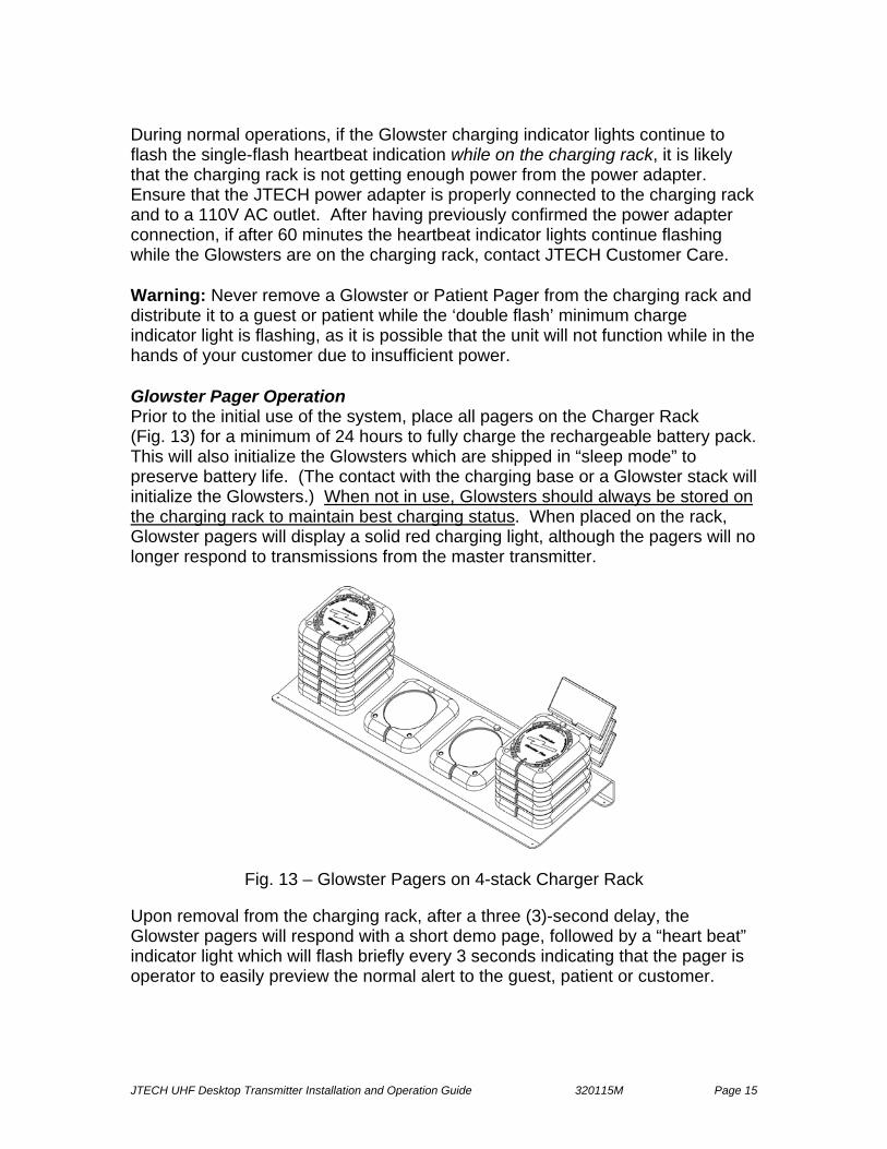
During normal operations, if the Glowster charging indicator lights continue to flash the single-flash heartbeat indication while on the charging rack, it is likely that the charging rack is not getting enough power from the power adapter. Ensure that the JTECH power adapter is properly connected to the charging rack and to a 110V AC outlet. After having previously confirmed the power adapter connection, if after 60 minutes the heartbeat indicator lights continue flashing while the Glowsters are on the charging rack, contact JTECH Customer Care. Warning: Never remove a Glowster or Patient Pager from the charging rack and distribute it to a guest or patient while the ‘double flash’ minimum charge indicator light is flashing, as it is possible that the unit will not function while in the hands of your customer due to insufficient power. Glowster Pager Operation Prior to the initial use of the system, place all pagers on the Charger Rack (Fig. 13) for a minimum of 24 hours to fully charge the rechargeable battery pack. This will also initialize the Glowsters which are shipped in “sleep mode” to preserve battery life. (The contact with the charging base or a Glowster stack will initialize the Glowsters.) When not in use, Glowsters should always be stored on the charging rack to maintain best charging status. When placed on the rack, Glowster pagers will display a solid red charging light, although the pagers will no longer respond to transmissions from the master transmitter.
Fig. 13 – Glowster Pagers on 4-stack Charger Rack Upon removal from the charging rack, after a three (3)-second delay, the Glowster pagers will respond with a short demo page, followed by a “heart beat” indicator light which will flash briefly every 3 seconds indicating that the pager is operator to easily preview the normal alert to the guest, patient or customer.
JTECH UHF Desktop Transmitter Installation and Operation Guide 320115M Page 16
Receiving Pages To page a Glowster pager, type the pager number followed by the # key on the master transmitter keypad. The pager will respond with the default alert that has been programmed into the master transmitter. The factory default is Alert 3.
Ex. If “Default # Vibes ?” on the transmitter has been set to “3” the pager will respond with three (3) 15 second alert cycles for a total 45 second page alert.
You can also send an individual alert that is different from the default by entering a “0” before the pager number and enter the alert number after the “#”. (See Table 1 for complete alert definitions.) Ex. Send a fifteen (15) minute alert (alert 5) to pager #12.
On the master transmitter keypad type in “0 1 2 # 5”. (This particular feature is also referred to as “long page”.)
Optional “Tone” Glowster An optional version of the Glowster pager includes Tone alerts, providing 3 short bursts of a double tone alert prior to the standard vibration and flash alerts. Should the Tone Glowster be ordered, and it be subsequently decided that the tone is undesirable, the tone can be deactivated from the transmitter by sending the “Audible OFF” transmission. This command can be activated by pressing 9995# from the transmitter keypad. It is essential that all Glowster pagers be off the charging rack and not stacked to be able to “hear” the “Audible OFF” command. Standard Glowster Alerts
Alert 1 – Vibe, and Flash for 1 15-second cycle. Alert 2 – Vibe, and Flash for 2 15-second cycles (30 Sec.) Alert 3 – Vibe, and Flash for 3 15-second cycles (45 Sec.) Alert 4 – Vibe, and Flash for 4 15-second cycles (60 Sec.) Alert 5 – Vibe, and Flash for 60 15-second cycles (15 Minutes)
All standard Glowster alerts are preceded by the pulse tones with the Tone Glowster pager. Again, the factory default setting is Alert 3.

JTECH UHF Desktop Transmitter Installation and Operation Guide 320115M Page 17
Glowster Promoback Installation/Removal Field installation of Glowster promoback option (Fig. 14):
1. Remove promoback screw. 2. Place the promoback over the alignment boss (upper left of the pager.) 3. Rotate the promoback clockwise until it snaps into place. 4. Reinstall promoback screw.
Fig. 14 – Installing Glowster Promoback Option Glowster Charger Rack The Charger Rack is a multi-functional base unit on which the Glowster pagers are stacked and stored for convenient usage (Fig. 15), as well as charging. When placed on the rack, Glowsters no longer receive or respond to transmissions from the master transmitter. The 1-stack and 4-stack rack options support a maximum of 15 and 60 Glowster pagers respectively, with15 Glowsters per stack.
Fig. 15 – Glowster Charger Rack Fig. 16 – Wooden Storage Rack A wooden storage rack option is also available for both the 1-stack and the 4-stack charger racks to assist in management and storage of the Glowster pagers (Fig. 16.) The wooden rack is designed to include the charger rack and up to 60 Glowster pagers (4 stacks of 15) configured with or without the optional pager promoback attachment. Care and Maintenance Wipe vibe/flash pagers with a soft cloth moistened with mild soap and water. Never spray liquids (cleaning solution or water) directly on the pagers.

JTECH UHF Desktop Transmitter Installation and Operation Guide 320115M Page 18
Glowster Special Functions Out-of-Range Alert The Out-of-Range (OOR) alert will notify the guest, patient or customer that he/she has traveled beyond the range of the transmitter and will not be able to receive notification when service is available. The OOR tone alert will repeat every three (3) seconds for five (5) minutes while the Glowster remains Out-of-Range. Glowster Voice pagers for restaurants will supplement the OOR tone alert with a periodic OOR alert voice prompt (see Voice Prompts below). After five (5) continuous minutes of OOR alert messaging, the OOR alert on the individual pager will cease. The OOR mode may be turned ON from the master transmitter function menu or by typing 9996 # from the keypad or phone, and turned OFF with the command 9997 #. NOTE: If the Out-of-Range feature is to be used, range testing is required in order to most accurately set the transmitter power level. For more information, please refer to the Transmission Power Adjustment (Appendix C) and Range Test sections of this Guide. Search The Search feature is intended to provide a method to recover pagers discarded within the transmitter coverage area. A special Search transmission is sent by the master transmitter approximately every 12 seconds. All “awake” Glowster pagers within range of the transmitter will respond with Search alert (Tone or Voice, depending on product purchased) at 12-second intervals. Search is turned on from the master transmitter via the menu or by typing in 9999 # from the keypad or phone. Pressing any key on the transmitter keypad will terminate Search mode. Glowster with Voice If the Glowster with Voice model for Restaurants was purchased, the pagers can be set to respond with appropriate voice prompts for Alert #1 through Alert #5, Search, and Out-of-Range. Voice prompts may be controlled from the master transmitter by typing in “ 9994# (ON) and 9995# (OFF) ” on the keypad or phone. Proper implementation of the Voice (Audible) on/off function requires that all Glowster pagers be “awake” (off the charger rack) in order to recognize the transmission. The Voice Prompts are: Alert 1 – 5: “Your table is ready. Please return to the hostess.” Out-of-Range: “You are Out-of-Range and cannot receive a page.” Search: “I’m not lost, I’m over here.”
JTECH UHF Desktop Transmitter Installation and Operation Guide 320115M Page 19
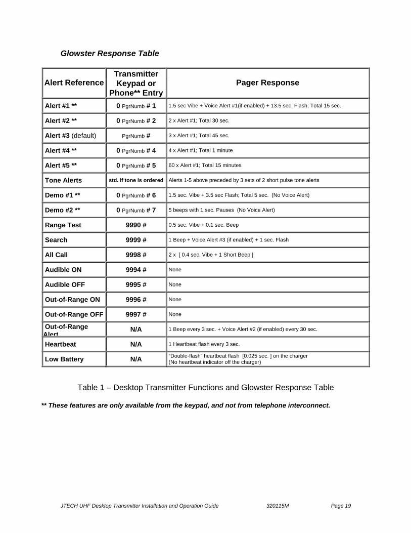
Glowster Response Table
Alert Reference Transmitter Keypad or
Phone** Entry Pager Response
Alert #1 ** 0 PgrNumb # 1 1.5 sec Vibe + Voice Alert #1(if enabled) + 13.5 sec. Flash; Total 15 sec.
Alert #2 ** 0 PgrNumb # 2 2 x Alert #1; Total 30 sec.
Alert #3 (default) PgrNumb # 3 x Alert #1; Total 45 sec.
Alert #4 ** 0 PgrNumb # 4 4 x Alert #1; Total 1 minute
Alert #5 ** 0 PgrNumb # 5 60 x Alert #1; Total 15 minutes
Tone Alerts std. if tone is ordered Alerts 1-5 above preceded by 3 sets of 2 short pulse tone alerts
Demo #1 ** 0 PgrNumb # 6 1.5 sec. Vibe + 3.5 sec Flash; Total 5 sec. (No Voice Alert)
Demo #2 ** 0 PgrNumb # 7 5 beeps with 1 sec. Pauses (No Voice Alert)
Range Test 9990 # 0.5 sec. Vibe + 0.1 sec. Beep
Search 9999 # 1 Beep + Voice Alert #3 (if enabled) + 1 sec. Flash
All Call 9998 # 2 x [ 0.4 sec. Vibe + 1 Short Beep ]
Audible ON 9994 # None
Audible OFF 9995 # None
Out-of-Range ON 9996 # None
Out-of-Range OFF 9997 # None
Out-of-Range Alert
N/A 1 Beep every 3 sec. + Voice Alert #2 (if enabled) every 30 sec.
Heartbeat N/A 1 Heartbeat flash every 3 sec.
Low Battery N/A “Double-flash” heartbeat flash [0.025 sec. ] on the charger (No heartbeat indicator off the charger)
Table 1 – Desktop Transmitter Functions and Glowster Response Table
** These features are only available from the keypad, and not from telephone interconnect.

JTECH UHF Desktop Transmitter Installation and Operation Guide 320115M Page 20
Using the CommPass™ Pager General Description The CommPass pagers include a standard promotional area that can be easily customized by the user for branding or promotional advertising to cater to guests, patients, families and shoppers. Each CommPass pager ships with its’ standard promotional (promo) insert that is color/texture coordinated and specific to the distinct market where it will be used.
Fig. 17 – CommPass Pagers
“Promo” Lens The promo lens (Fig. 18) is designed to securely protect your promotional piece while also providing access to the battery compartment as needed. The promo lens is held in place by two latches, accessible with a special “key” that ships attached to each CommPass charger. This key is also available as an accessory purchase.
Fig. 18 – CommPass Promo Lens and Latch Opening Areas
Promo lens (place insert inside)
Latch openings (insert key from top)

JTECH UHF Desktop Transmitter Installation and Operation Guide 320115M Page 21
Pager Operation Prior to the initial use of the system, place all CommPass pagers in the CommPass Charger for a minimum of 12 hours to fully charge the rechargeable battery pack. This action will also initialize the pagers, which are shipped in “sleep mode.” When not in use, CommPass pagers should always be stored in the charger. When placed in the charger, CommPass pagers will not respond to transmissions from the master transmitter.
Fig. 19a – CommPass Charger Fig. 19b – Heartbeat Upon removal from the charger, the CommPass pager will respond with a short demo page, followed by the “heartbeat” indicator light (backlit pager number at base of pager, Fig. 13b) which will flash approximately every 3 seconds indicating that the pager is awake and ready to receive pages. This initial demo page also allows preview of the normal alert to the guest, patient, customer, etc.
CommPass Charger CommPass pagers are stored in the Charger (Fig. 19a) for convenient usage. The pager receiver is deactivated when placed in the charger (i.e. it will not respond if paged from the transmitter.) The CommPass charger efficiently stores 20 CommPass pagers in a minimum space. The CommPass charger can be daisy chained to a maximum of three (3) chargers (supporting up to 60 pagers) on a single specialized power supply also available from JTECH. A small green power indicator light is visible in the center of the charger base between the pager stacks, which will illuminate when power is properly supplied to the charger.
JTECH UHF Desktop Transmitter Installation and Operation Guide 320115M Page 22
Securing the CommPass Charger The CommPass Charger can be placed on a desk or counter top “as is” with no additional installation. If desired, however, the charger can also be secured to a desk, counter top or be wall-mounted using the mounting bracket included with each charger. To install the mounting bracket, follow the instruction sheet included with the bracket.
CommPass Pager Charge Indicator Under normal operations, when in the charger, CommPass pagers display a solid green charge indicator ‘ready’ light, illuminating the pager ID number at the base (foot) of the unit as depicted in Fig. 19b above. Out of the charger, the green backlit pager ID number will flash intermittently displaying a normal “heartbeat” when the pager is in use. Should the pager enter a low battery state, this flashing green heartbeat indicator will change to a flashing yellow, indicating a need for recharging. When placed in the charger in a low battery state, the charge indicator light will display a yellow “double flash” every second, indicating that the unit has entered the 30-minute mandatory minimum charge period. After 30-minutes, the yellow ‘”double-flash” will be replaced by a solid yellow indicator for an additional 30 minutes, completing the 1-hour minimum charge routine. After 1-hour in the charger, the yellow indicator will return to the green ‘ready’ state. This will indicate the pager should have sufficient power to be used to complete an average work shift (3-5 hours), but not necessarily have a complete charge. (An 8-hour pager re-charge is recommended at this point.) For optimal performance, CommPass pagers should charge for a minimum of 2-6 hours to become completely recharged, depending on the degree of available charge in any given pager at time of recharging. When not in use, CommPass pagers should always be store in the charger. When out of the charger, if the CommPass detects insufficient battery power for an extended period of time, the charge indicator light will cease to illuminate altogether, and the unit will enter a non-functional “sleep” state until placed back in the charger where it will enter the 1-hour mandatory minimum charge routine. Note: If a CommPass pager is removed from the charger during the initial 30-minute “double-flash” minimum charge period, the pager remains non-functional.

JTECH UHF Desktop Transmitter Installation and Operation Guide 320115M Page 23
Sending Pages To page a CommPass pager, type the pager number followed by the “#” key on the master transmitter keypad or phone. The pager will respond with the default alert that has been programmed into the master transmitter. The factory default is Alert 3.
Individual alerts different from the factory default may be sent by entering a “0”
before the pager number, followed by the pager number and the “#” key. Next enter the alert number (1-5) when prompted followed by the “#” key. (This operation is not supported from the telephone interconnect option.)
Ex. Send the “Alert 5” (15-minute extended alert) to pager number 23.
From the transmitter keypad, type in “0 2 3 #” followed by “5 #”. Note: Depending on install date, some legacy PeopleAlert system transmitters
may not support the “Default # of Vibes” feature from the transmitter menu. Please consult JTECH Customer Care for additional instruction.
Search The Search feature is intended to provide a method to recover pagers discarded within the transmitter coverage area. A “Search” transmission is sent from the transmitter approximately every 12 seconds. All “awake” CommPass pagers within range of the transmitter will respond with standard CommPass Voice Search Response at 12 second intervals. Search is turned on from the master transmitter via the menu or by typing 9999 # on the keypad or phone. Pressing any key on the transmitter keypad or phone will terminate Search mode.
Voice Alerts All CommPass pagers offer standard voice alerts for “Out of Range” and “Search.” These voice alert features can reduce loss and improve usability for the end-user. Standard voice alerts include: Out-of-Range: “You are Out-of-Range and cannot receive a page.”
Search: “I’m not lost, I’m over here.” If the GuestPass with ‘Table Ready’ Voice Alert model was purchased, the pagers will respond with appropriate voice prompts for Alerts #1 through #5 “Your table is ready. Please return to the hostess,” as well. Table Ready voice alerts may be turned on and off from the Desktop Transmitter using the ‘Audible ON/OFF’ commands (9994# / 9995#) or from the function menu. Note that CommPass pagers must be “awake” (out of the charger) in order to recognize the Audible ‘ON’ and ‘OFF’ transmissions. Voice requirements for non-hospitality markets and custom voice alerts for restaurant applications are handled on a case-by-case basis due to the custom nature of these business opportunities. In these cases, the client may be responsible for providing the proper voice file to meet the JTECH specification.
JTECH UHF Desktop Transmitter Installation and Operation Guide 320115M Page 24
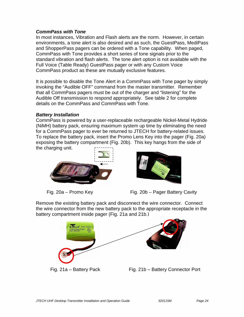
CommPass with Tone In most instances, Vibration and Flash alerts are the norm. However, in certain environments, a tone alert is also desired and as such, the GuestPass, MediPass and ShopperPass pagers can be ordered with a Tone capability. When paged, CommPass with Tone provides a short series of tone signals prior to the standard vibration and flash alerts. The tone alert option is not available with the Full Voice (Table Ready) GuestPass pager or with any Custom Voice CommPass product as these are mutually exclusive features. It is possible to disable the Tone Alert in a CommPass with Tone pager by simply invoking the “Audible OFF” command from the master transmitter. Remember that all CommPass pagers must be out of the charger and “listening” for the Audible Off transmission to respond appropriately. See table 2 for complete details on the CommPass and CommPass with Tone. Battery Installation CommPass is powered by a user-replaceable rechargeable Nickel-Metal Hydride (NiMH) battery pack, ensuring maximum system up time by eliminating the need for a CommPass pager to ever be returned to JTECH for battery-related issues. To replace the battery pack, insert the Promo Lens Key into the pager (Fig. 20a) exposing the battery compartment (Fig. 20b). This key hangs from the side of the charging unit. Fig. 20a – Promo Key Fig. 20b – Pager Battery Cavity Remove the existing battery pack and disconnect the wire connector. Connect the wire connector from the new battery pack to the appropriate receptacle in the battery compartment inside pager (Fig. 21a and 21b.) Fig. 21a – Battery Pack Fig. 21b – Battery Connector Port

JTECH UHF Desktop Transmitter Installation and Operation Guide 320115M Page 25
Once the battery pack is installed, replace the promo insert and the lens cover. After installing the replacement battery pack, the charge indicator should be visible. Charge the pager for at least 2 hours. If the promo key was removed from the bungee cord hanging on the charger, return it to that clasp so that it will be available the next time that it is required. NOTE: As a consumable item, the standard warranty on the rechargeable NiMH battery pack is 90-days. If a battery-related failure is experienced during this time, simply contact JTECH Customer Care for a replacement. Outside of the 90-day warranty period, JTECH offers a replacement NiMH battery pack at a nominal charge, which can be ordered with part number 232020. Promo Insert Installation Listed below are the steps depicting the process of inserting a new promo insert into the CommPass promo area:
1. Insert key into latch area at top of CommPass pager, releasing the lens. 2. Open the promo lens area by first sliding the lens “down” in the direction of
the base, and then rotating the lens away from the pager housing. 3. Remove, replace and secure the promo insert (Fig. 22). 4. To re-attach the lens, re-position the tabs at the base of the promo lens
into the slots at the base of the CommPass pager housing, sliding the lens “up” in the direction of the “top” of the pager.
5. “Close” the promo lens until the tongue latches on the inside top of the lens cover slide into the slots in the CommPass pager housing and the unit “clicks” shut.
Fig. 22 – Installing the CommPass Promo Insert
Care and Maintenance Wipe CommPass pagers with a soft cloth moistened with mild soap and water. Never spray liquids (cleaning solution or water) directly on the pagers.
“base”
“top”

JTECH UHF Desktop Transmitter Installation and Operation Guide 320115M Page 26
CommPass Pager Response Table
Alert Reference CommPass Pager Response
Alert #1* 1.5 sec Vibe + Voice “Table Ready” Alert (GuestPass only, if enabled) + 13.5 sec. Flash; Total 15 sec.
Alert #2* 2 x Alert #1; Total 30 sec.
Alert #3* (default) 3 x Alert #1; Total 45 sec.
Alert #4* 4 x Alert #1; Total 1 minute
Alert #5* (“long page”) 60 x Alert #1; Total 15 minutes
* Tone Alerts Alerts 1-5 above preceded by three 2x pulse tones
Range Test 0.5 sec. Vibe + 1 sec. Flash
Search Voice Alert (“I’m not lost, I’m over here.”) + 1 sec. Flash
All Call A short Vibe alert, followed by an extended Flash alert (total 2 seconds)
Out-of-Range (OOR) 10 single tone (beep) alerts followed by the Voice alert “You are out of range and cannot receive the page.” OOR alert sequence repeated every 30 sec. with a 5-minute alert timeout.
Heartbeat 1 Heartbeat flash every 2.5 sec.
Low Battery (Out of Chgr.) Pager ID Back-light displays flashing Yellow
Low Battery (In Chgr.) Pager ID Back-light displays a “double flash” or so lid Yellow depending on battery state
Table 2 – CommPass Pager Response Table
Promo Insert Specifications Users may elect to design and produce their own promotional inserts. JTECH and our graphics partners offer this service with easy access via the JTECH website at www.jtech.com.
JTECH UHF Desktop Transmitter Installation and Operation Guide 320115M Page 27
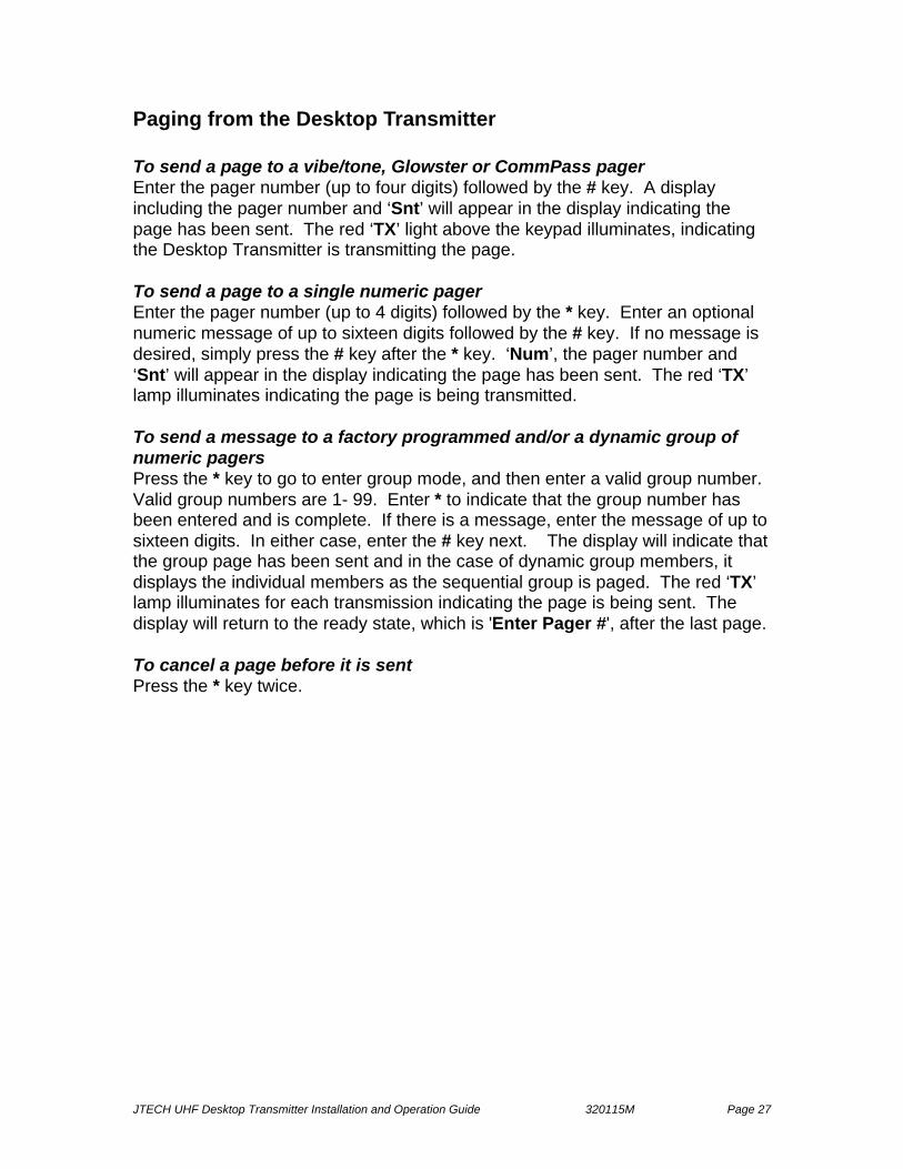
Paging from the Desktop Transmitter To send a page to a vibe/tone, Glowster or CommPass pager Enter the pager number (up to four digits) followed by the # key. A display including the pager number and ‘Snt’ will appear in the display indicating the page has been sent. The red ‘TX’ light above the keypad illuminates, indicating the Desktop Transmitter is transmitting the page. To send a page to a single numeric pager Enter the pager number (up to 4 digits) followed by the * key. Enter an optional numeric message of up to sixteen digits followed by the # key. If no message is desired, simply press the # key after the * key. ‘Num’, the pager number and ‘Snt’ will appear in the display indicating the page has been sent. The red ‘TX’ lamp illuminates indicating the page is being transmitted. To send a message to a factory programmed and/or a dynamic group of numeric pagers Press the * key to go to enter group mode, and then enter a valid group number. Valid group numbers are 1- 99. Enter * to indicate that the group number has been entered and is complete. If there is a message, enter the message of up to sixteen digits. In either case, enter the # key next. The display will indicate that the group page has been sent and in the case of dynamic group members, it displays the individual members as the sequential group is paged. The red ‘TX’ lamp illuminates for each transmission indicating the page is being sent. The display will return to the ready state, which is 'Enter Pager #', after the last page. To cancel a page before it is sent Press the * key twice.

JTECH UHF Desktop Transmitter Installation and Operation Guide 320115M Page 28
Paging Using the Telephone Interconnect Paging a Single Pager using the Telephone Interconnect 1. Pick up the receiver, listen for the dial tone, and dial the dedicated analog
system extension that has been assigned to the Paging System. A beep indicates the system has answered and is ready for you to enter the pager number.
2. Within 20 seconds, press the number of the pager (up to four digits) you wish to page, using the telephone keypad.
3. For a non-data (numeric or alphanumeric) pager, press the # key next to send the page. For a numeric page, enter the pager number up to four digits followed by the * key, and then enter an optional message up to 16 digits followed by the # key. A beep is heard verifying the message was sent. If the numeric message is exactly 16 digits, the beep is heard once the 16th digit is entered.
4. Hang up the receiver.
Group Paging Using the Telephone Interconnect 1. Pick up the receiver, listen for the dial tone, and dial any of the dedicated
analog system extensions that have been assigned to the Paging System. You will hear a single beep indicating the system has answered and is ready for you to enter the group number.
2. Within 20 seconds press the * key followed by the number of the group (1-99) you wish to page using the telephone keypad.
3. Press the * key again to continue with a numeric message or press the # key to transmit without a message.
4. Enter an optional message of up to 16 digits. If the message is less than 16 characters, press the # key on the phone keypad to indicate the end of the message and send the page. A beep is heard verifying the message was sent. If the message is exactly 16 digits, the beep is heard once the 16th digit is entered.
5. Hang up the receiver.
JTECH UHF Desktop Transmitter Installation and Operation Guide 320115M Page 29
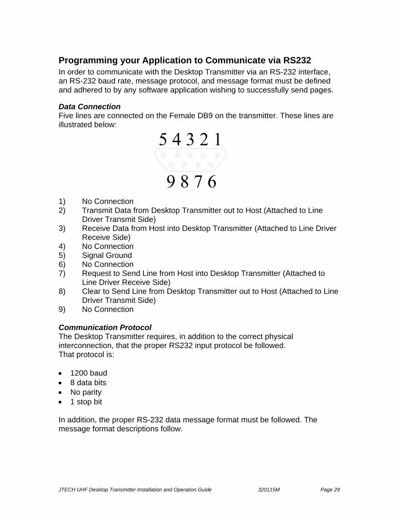
Programming your Application to Communicate via RS232 In order to communicate with the Desktop Transmitter via an RS-232 interface, an RS-232 baud rate, message protocol, and message format must be defined and adhered to by any software application wishing to successfully send pages. Data Connection Five lines are connected on the Female DB9 on the transmitter. These lines are illustrated below:
1) No Connection 2) Transmit Data from Desktop Transmitter out to Host (Attached to Line
Driver Transmit Side) 3) Receive Data from Host into Desktop Transmitter (Attached to Line Driver
Receive Side) 4) No Connection 5) Signal Ground 6) No Connection 7) Request to Send Line from Host into Desktop Transmitter (Attached to
Line Driver Receive Side) 8) Clear to Send Line from Desktop Transmitter out to Host (Attached to Line
Driver Transmit Side) 9) No Connection Communication Protocol The Desktop Transmitter requires, in addition to the correct physical interconnection, that the proper RS232 input protocol be followed. That protocol is: • 1200 baud • 8 data bits • No parity • 1 stop bit In addition, the proper RS-232 data message format must be followed. The message format descriptions follow.

JTECH UHF Desktop Transmitter Installation and Operation Guide 320115M Page 30
RS232 Interface Hardware Handshaking-Request To Send / Clear To Send While the Desktop Transmitter does not monitor RTS, it does toggle Clear to Send (CTS) to allow it to meter data out of the Host output buffer. Therefore, the Host must observe CTS from the transmitter and never send any data while CTS is low. Any data sent while CTS is low will be lost!
The Desktop Transmitter uses only CTS to indicate when it is OK to send data to the unit. The transmitter expects the host will cease sending data immediately upon dropping CTS from High to Low.
Some specialized high-speed serial port drivers will buffer up to 16 characters and will continue to send data long after CTS has dropped. This causes important data to be lost since the Desktop Transmitter is not paying attention to the incoming data while CTS is low. Generally these specialized high-speed serial port drivers allow you to set the amount of data that will be buffered and therefore sent upon the dropping of CTS. If this is your situation, set this parameter to 1 or 0.
Windows 95 & Windows 3.1X serial port drivers perform as expected and cease sending characters immediately upon the transition of CTS from High to Low. Baud Rate The RS-232 baud rate required by the Desktop Transmitter is summarized below: • 1200,N,8,1 (1200 Baud, No Parity, 8 Data Bits, 1 Stop Bit)

JTECH UHF Desktop Transmitter Installation and Operation Guide 320115M Page 31
Message Format The message format is a 7-digit extended format. The 7-digit extended format consists of six parts:
1. Preamble 2. Function Bit 3. Cap Code 4. Separator 5. Pager Message 6. Terminator
A code sample is shown below. Please refer to this example as you read through the sections that describe each part of the message. The 7-digit format allows the Desktop Transmitter to access one type of pager baud rate (512), two types of pager data (alphanumeric and numeric only), all four function bits (01 through 04) enabling priority messaging, and two types of messages (Non inverted and Inverted). Below is an excerpt from a simple visual basic software program utilizing 7-digit extended format, which will result in a non-inverted, non-priority page, to a 512 RF baud alphanumeric pager: MSComm1.PortOpen = True ‘Opens Serial Port for Communication
Preamble = Chr$(255) & Chr$(255) & Chr$(255) FBit = Chr$(03) ‘Set Function bit #3 (non-priority for alpha) Cap Code = “2049950” (where ‘204’ is the cap code prefix and ‘9950’ is the pager ID) Separator = Chr$(10) ‘This is an Non Inverted,512 RF baud, Alpha Page PagerMessage = “This is a test Page” Terminator = Chr$(13) OutPutString = Preamble & Fbit & CapCode & Separator & PagerMessage & Terminator MSComm1.Output = OutPutString Example Data Stream Into Desktop UHF: (Expressed in hex) FF FF FF 03 32 30 34 39 39 39 39 0A 54 48 49 53 20 49 53 20 41 20 54 45 53 54 20 50 41 47 45 OD | P | F |Cap Code:2049999 | S| Message: THIS IS A TEST PAGE | T | P = Preamble F = Function Bit (Byte) Cap Code = Seven Digits (the 3-digit cap code prefix should match the cap code prefix stored in the desktop transmitter; the remaining 4 digits represent the pager ID) S = Separator Message = Up to 16 Numeric Characters or Alphanumeric 120 Characters (function determines numeric or alpha) T = Terminator

JTECH UHF Desktop Transmitter Installation and Operation Guide 320115M Page 32
Details of the Message Parts 1. Preamble Preamble is a string of three hex characters used to provide start up synchronization “padding” between messages in an output buffer as well as information to the Desktop Transmitter that a paging message is on its way. The Preamble is Chr$(255) & Chr$(255) & Chr$(255) 2. Function Bit The function bit is actually a byte and is a single hex character, which follows immediately after the preamble. This character signifies to the Desktop Transmitter which function bit to “Turn On” in the POCSAG message that is sent. The selection of function bits in the transmitted message allows the application developer to exploit various functions, which reside inside the pager. Function bits in the transmitted message by themselves do not evoke functions from the pager, rather they must match functions which are pre-programmed into the pager before they cause a pager to operate in a particular fashion. For our purposes here, one of four hex characters are available to select function bits in the transmitted message. Hex 01 to hex 04 are the acceptable characters. The following table shows, which function bits, evoke what pager reactions. Function Bit (Only One May Be Set)
Char $ Function accessed from Pager
Function Bit #1 Enabled 01 Non Priority Alert for Numeric Only Pagers Function Bit #2 Enabled 02 Priority Alert for Numeric Only Pagers Function Bit #3 Enabled 03 Non Priority Alert for Alphanumeric Pagers Function Bit #4 Enabled 04 Priority Alert for Alphanumeric Pagers 3. Cap Code Cap Code for 7-digit extended Message Format In the seven-digit extended format no assumptions or cross-references are made and the seven-digit pager cap code sent is the actual seven-digit pager cap code received by the pager. Application developers will find the seven digit extended format provides maximum flexibility. Important note: If the cap code prefix (first 3-digits) of 000 is used, the Desktop Transmitter recognizes this as the JTECH “times 8” (X8) cap code scheme. The transmitter multiplies the pager ID portion of the cap code number (last 4-digits) provided by 8 prior to transmission to the pager. For example, the JTECH pager may have two labels. One will be the ‘pager ID’ number the other will be the cap code number or reference. In a ‘times 8’ cap code scheme, the pager ID number will be the last four digits of the 7-digit cap code divided by 8. With the times 8 scheme, be sure to use the pager ID number in your program. All other cap codes using valid prefixes will be sent as entered into the program.
JTECH UHF Desktop Transmitter Installation and Operation Guide 320115M Page 33
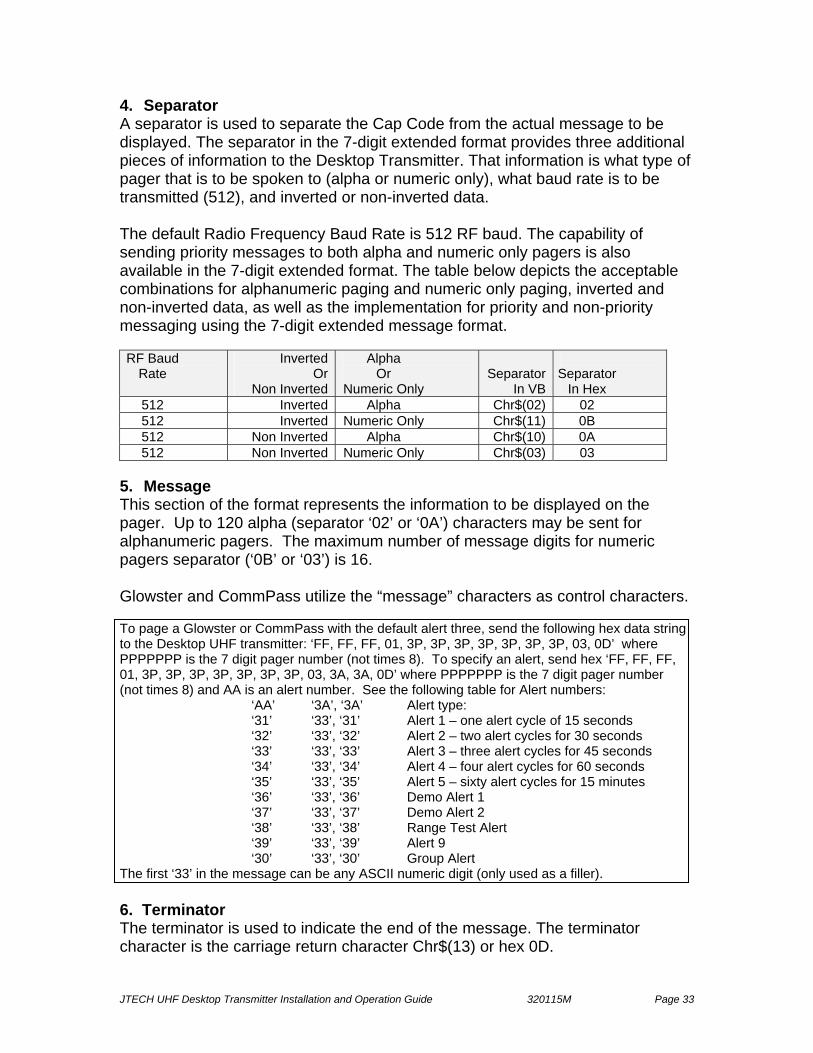
4. Separator A separator is used to separate the Cap Code from the actual message to be displayed. The separator in the 7-digit extended format provides three additional pieces of information to the Desktop Transmitter. That information is what type of pager that is to be spoken to (alpha or numeric only), what baud rate is to be transmitted (512), and inverted or non-inverted data. The default Radio Frequency Baud Rate is 512 RF baud. The capability of sending priority messages to both alpha and numeric only pagers is also available in the 7-digit extended format. The table below depicts the acceptable combinations for alphanumeric paging and numeric only paging, inverted and non-inverted data, as well as the implementation for priority and non-priority messaging using the 7-digit extended message format. RF Baud
Rate Inverted
OrNon Inverted
Alpha Or
Numeric Only Separator
In VB
Separator
In Hex 512 Inverted Alpha Chr$(02) 02 512 Inverted Numeric Only Chr$(11) 0B 512 Non Inverted Alpha Chr$(10) 0A 512 Non Inverted Numeric Only Chr$(03) 03
5. Message This section of the format represents the information to be displayed on the pager. Up to 120 alpha (separator ‘02’ or ‘0A’) characters may be sent for alphanumeric pagers. The maximum number of message digits for numeric pagers separator (‘0B’ or ‘03’) is 16. Glowster and CommPass utilize the “message” characters as control characters. To page a Glowster or CommPass with the default alert three, send the following hex data string to the Desktop UHF transmitter: ‘FF, FF, FF, 01, 3P, 3P, 3P, 3P, 3P, 3P, 3P, 03, 0D’ where PPPPPPP is the 7 digit pager number (not times 8). To specify an alert, send hex ‘FF, FF, FF, 01, 3P, 3P, 3P, 3P, 3P, 3P, 3P, 03, 3A, 3A, 0D’ where PPPPPPP is the 7 digit pager number (not times 8) and AA is an alert number. See the following table for Alert numbers:
‘AA’ ‘3A’, ‘3A’ Alert type: ‘31’ ‘33’, ‘31’ Alert 1 – one alert cycle of 15 seconds ‘32’ ‘33’, ‘32’ Alert 2 – two alert cycles for 30 seconds ‘33’ ‘33’, ‘33’ Alert 3 – three alert cycles for 45 seconds ‘34’ ‘33’, ‘34’ Alert 4 – four alert cycles for 60 seconds ‘35’ ‘33’, ‘35’ Alert 5 – sixty alert cycles for 15 minutes ‘36’ ‘33’, ‘36’ Demo Alert 1 ‘37’ ‘33’, ‘37’ Demo Alert 2 ‘38’ ‘33’, ‘38’ Range Test Alert ‘39’ ‘33’, ‘39’ Alert 9 ‘30’ ‘33’, ‘30’ Group Alert
The first ‘33’ in the message can be any ASCII numeric digit (only used as a filler). 6. Terminator The terminator is used to indicate the end of the message. The terminator character is the carriage return character Chr$(13) or hex 0D.

JTECH UHF Desktop Transmitter Installation and Operation Guide 320115M Page 34
Appendix A – Transmitter Function Menu Function Menu Descriptions The following table lists the special functions available from the transmitter keypad with the Desktop Transmitters. (Many functions are accessible from the telephone interconnect although some are not.) From the transmitter keypad, press the * key to scroll down through the features menu; press # to enter a function; press 0 to scroll up through functions. Pressing an invalid key in the Main Menu will display ‘Invalid’ and return to ‘Enter Pager #.’
Follow the instructions shown below to activate a special feature. To return to the paging mode, scroll to the end of the special function menu and the unit will automatically return to the paging mode.
Function Description Replace Pager Scroll Down * Scroll Up 0 Enter Function # (Return a Pager to the original Pager ID)
Logically replaces pagers. Input the old pager number (1 to 4 digits), #, the new pager number (1 to 4 digits), #, and the kind of pager (2 screens of options, press # to get to the second screen. Pager type selection is done by entering a 1, 2, 3, or 4 from the screen; touch # to scroll to screen 2). To repeat the replace pager operation, press # again. Up to 500 old pagers may be replaced. After the Replace Pager entry, the new pager will be paged when the old pager number is entered. To remove an entry in the replace table and return the pager to its original pager ID, enter the original pager number as the old pager number and enter zero for the new pager number. A confirmation message will say that the Original pager number has been removed.
Display Pager Scroll Down * Scroll Up 0 Enter Function #
Displays all pagers that have been replaced. The # key takes you forward to the next entry; zero takes you back to the previous entry. Exit the function by pressing the * key at any time.
Add Pager to Dynamic Group Scroll Down * Scroll Up 0 Enter Function #
99 Dynamic Groups can be programmed. The first 9 (1 – 9) are transmitted with the factory pre-programmed groups with the same number. To build a group of pagers that will be paged in rapid succession (Dynamic Group), press # at this menu item. When asked ‘Which Group’, enter a one or two digit group number. When asked ‘Which pager’ enter the last pager on the group list (Dynamic groups are paged in the reverse order of entry). The pager type must be selected by entering 1, 2, 3, or 4, which identifies the pager as POC, Glwstr, NUM, or ALP (alpha). (Select “Glwstr” for COMMPASS pagers.) Press # after this entry to enter another pager in the same dynamic group. Press * when the last entry has been made. Up to 500 pagers may be entered in dynamic groups. Pagers entered in dynamic groups will be replaced if they are entered in the replace pager table. As Dynamic Groups are built, users should ideally create each pager groups to consist of 10-12 pagers so that the transmission period does not tie up the transmitter. Groups can consist of a mixture of pager types. The transmitter cannot be used for other pages while pages from the dynamic group are being transmitted.
JTECH UHF Desktop Transmitter Installation and Operation Guide 320115M Page 35
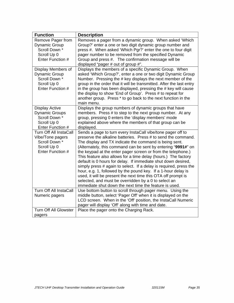
Function Description Remove Pager from Dynamic Group Scroll Down * Scroll Up 0 Enter Function #
Removes a pager from a dynamic group. When asked ‘Which Group?’ enter a one or two digit dynamic group number and press #. When asked ‘Which Pgr?’ enter the one to four digit pager number to be removed from the specified Dynamic Group and press #. The confirmation message will be displayed “pager # out of group #”.
Display Members of Dynamic Group Scroll Down * Scroll Up 0 Enter Function #
Displays the members of a specific Dynamic Group. When asked ‘Which Group?’, enter a one or two digit Dynamic Group Number. Pressing the # key displays the next member of the group in the order that it will be transmitted. After the last entry in the group has been displayed, pressing the # key will cause the display to show ‘End of Group’. Press # to repeat for another group. Press * to go back to the next function in the main menu.
Display Active Dynamic Groups Scroll Down * Scroll Up 0 Enter Function #
Displays the group numbers of dynamic groups that have members. Press # to step to the next group number. At any group, pressing 0 enters the ‘display members’ mode explained above where the members of that group can be displayed.
Turn Off All InstaCall Vibe/Tone pagers Scroll Down * Scroll Up 0 Enter Function #
Sends a page to turn every InstaCall vibe/tone pager off to preserve the alkaline batteries. Press # to send the command. The display and TX indicate the command is being sent. (Alternately, this command can be sent by entering “9991#” on the keypad at the enter pager screen or from the telephone.) This feature also allows for a time delay (hours.) The factory default is 0 hours for delay. If immediate shut down desired, simply press # again to select. If a delay is required, press the hour, e.g. 1, followed by the pound key. If a 1-hour delay is used, it will be present the next time this OTA off prompt is selected, and must be overridden by a 0 to select an immediate shut down the next time the feature is used.
Turn Off All InstaCall Numeric pagers
Use bottom button to scroll through pager menu. Using the middle button, select ‘Pager Off’ when it is displayed on the LCD screen. When in the ‘Off’ position, the InstaCall Numeric pager will display ‘Off’ along with time and date.
Turn Off All Glowster pagers
Place the pager onto the Charging Rack.

JTECH UHF Desktop Transmitter Installation and Operation Guide 320115M Page 36
Function Description Send All Call Scroll Down * Scroll Up 0 Enter Function #
Sends a page to all InstaCall vibe/tone, Glowster and CommPass pagers. Press the # key to send the command. ‘Sending All Call’ appears in the display, indicating the command has been sent. Alternately, this command can be sent by entering “9998#” at the enter pager screen or from the phone.
Range Test Scroll Down * Scroll Up 0 Enter Function #
This feature allows you to conduct a range test. A range test is provided to verify the coverage area. Press # to turn on range test mode. The range test page will be sent approximately every 4 seconds. To exit the range test mode, press any key from the transmitter keypad or phone. Alternately, the Range Test command can be sent by entering “9990#” at the enter pager screen or from the phone. All pagers in Group #99 can be used.
Search Mode? Scroll Down * Scroll Up 0 Enter Function #
This feature allows for Glowster and CommPass pagers to be located in the coverage area. To activate, simply press the # key at the Search prompt. Glowsters off the charging rack within the coverage area will respond with a tone. Glowsters with Voice and CommPass family pagers will respond with the appropriate voice message. Touch any key to exit search mode. Alternately, the Search Mode command can be sent by entering “9999#” at the enter pager screen or from the phone.
Default # of Vibes Scroll Down * Scroll Up 0 Enter Function #
This feature allows for alerts 1-9 to be selected for the standard default alert for pages sent. This should always be set to a number between 1 and 5, corresponding to Alerts 1 – 5 as defined on Table 1. The factory default setting is 3.
Audible ON/OFF Scroll Down * Scroll Up 0 Enter Function #
This feature is used to turn ON or OFF the audible tone alerts as well as the voice table ready alert. Glowsters or CommPass family pagers must be off/out of the charger and not stacked to be able to ‘hear’ this OTA programming change. Shortcut commands are 9994# (ON) and 9995# (OFF) from the transmitter keypad or phone.
Out of Range (OOR) ON/OFF Scroll Down * Scroll Up 0 Enter Function #
This feature is used to turn ON or OFF the out of range transmissions at the transmitter. When OOR is active, the desktop transmitter sends an OOR transmission every 10 seconds. If this feature is active, a Glowster or CommPass pager will respond with the appropriate OOR tone/voice response after missing more than 2 consecutive OOR transmissions. It is strongly recommended that appropriate range testing be conducted in order to implement the OOR feature properly. Shortcut commands are 9996# (ON) and 9997# (OFF) from the transmitter keypad or phone.

JTECH UHF Desktop Transmitter Installation and Operation Guide 320115M Page 37
In the preceding chart, the features ask questions and use detailed messages. The messages and their meanings are explained below: Prompt Meaning Enter Pager # This message is the ‘Home Position’ of the Desktop Unit.
All other modes start here and are called to the screen by pressing *’s to scroll down through the menu entries, entering the password when prompted. To page a pager or its replacement, enter the original ‘old’ pager number here. That pager number may be followed by an * and then up to a 16 digit optional message and a # sign, or the pager number may be followed directly by a # sign for the vibe/tone pagers. This entry is also accepted from the telephone on the PeopleAlert with Telephone.
Enter Grp # __ Enter a group number 1 – 99 to page a group. This is followed by an *, an optional message and a #. This entry proceeded by the '*' is also accepted from the telephone on the PeopleAlert with Telephone.
Password This protects the balance of menu access by requiring a 4-digit password to be entered. The factory default is 1234. (A subsequent menu prompt allows for changing of this password.)
Turn Off Pagers? Prompt to turn off all InstaCall Vibe/Tone pagers via an Over-the-Air (OTA) transmission.
Old Pager # Enter the pager number to be replaced (1- 4 digits) New Pager # Enter the pager number that will replace the old pager (1-
4 digits) Enter Digit You have pressed something other than a number key
when a number key was expected. 1= POC Vib 2= Glwstr
Enter a one for a InstaCall (POCSAG) vibe/tone pager or two for a Glowster pager. To see the next prompt, press #. (3 or 4 may be pressed at this time without waiting for the next prompt.)
3= Numeric 4= Alpha
Enter a three for a InstaCall Numeric pager or four for an alphanumeric pager (one that can display letters as well as numbers). You can also press 1 or 2 at this prompt for POCSAG Vibe or Glowster pagers.
Replace Pager This can add an entry to the Replace Pager table so that every time the old pager number is designated to be transmitted, the new pager number will replace it. A pager may also be removed from the Replace Table by entering the old pager number used to set up the original replace followed by a new pager number of 0 (1 - 4 digits of 0). Some of the other screens presented during this mode are also explained in this chart.
JTECH UHF Desktop Transmitter Installation and Operation Guide 320115M Page 38
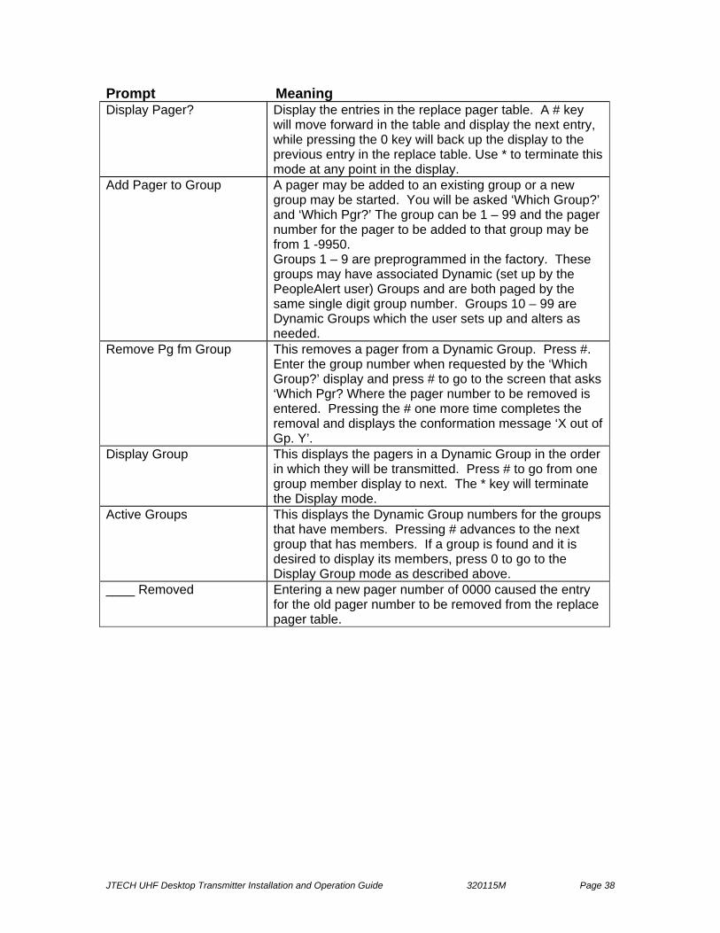
Prompt Meaning Display Pager? Display the entries in the replace pager table. A # key
will move forward in the table and display the next entry, while pressing the 0 key will back up the display to the previous entry in the replace table. Use * to terminate this mode at any point in the display.
Add Pager to Group A pager may be added to an existing group or a new group may be started. You will be asked ‘Which Group?’ and ‘Which Pgr?’ The group can be 1 – 99 and the pager number for the pager to be added to that group may be from 1 -9950. Groups 1 – 9 are preprogrammed in the factory. These groups may have associated Dynamic (set up by the PeopleAlert user) Groups and are both paged by the same single digit group number. Groups 10 – 99 are Dynamic Groups which the user sets up and alters as needed.
Remove Pg fm Group This removes a pager from a Dynamic Group. Press #. Enter the group number when requested by the ‘Which Group?’ display and press # to go to the screen that asks ‘Which Pgr? Where the pager number to be removed is entered. Pressing the # one more time completes the removal and displays the conformation message ‘X out of Gp. Y’.
Display Group This displays the pagers in a Dynamic Group in the order in which they will be transmitted. Press # to go from one group member display to next. The * key will terminate the Display mode.
Active Groups This displays the Dynamic Group numbers for the groups that have members. Pressing # advances to the next group that has members. If a group is found and it is desired to display its members, press 0 to go to the Display Group mode as described above.
____ Removed Entering a new pager number of 0000 caused the entry for the old pager number to be removed from the replace pager table.

JTECH UHF Desktop Transmitter Installation and Operation Guide 320115M Page 39
Appendix B – Technical Information
Vibration/Tone and Vibration/Flash Pagers (POC Types) Vibration/Tone pagers are not capable of displaying any information; they can simply vibrate, emit a tone, or flash. In some cases, vibe/flash pagers also offer pre-recorded voice alerts. (Glowster and CommPass pagers use “message” data, if present as alert control characters.) Numeric Pager (NUM type) Numeric pagers are capable of displaying 1 to 16 numeric digits. It will not display an alphabetic message. When this class of pager is targeted to receive a page it must receive a numeric only radio transmission. If a numeric only pager receives an alpha transmission sent to its ID, it will attempt to decode the message and will then display nonsense on the screen. Numeric only pagers are not ‘smart’ enough to know not to attempt to display alpha data. Therefore the software sending the transmission must be smart enough not to send alpha data to numeric only pagers. Alphanumeric Pager (ALP type) Alphanumeric pagers are capable of alpha or numeric characters with the exact capacity based on the individual pager model, transmitter and software. Most will display an alpha message as well as a numeric message. When this class of pager is targeted to receive a page, it may receive either numeric only or alpha data and if the pager is properly set up, it will display either type of data properly. Alphanumeric pagers require special set up and adherence to special transmission rules to properly display both alpha and numeric only radio transmissions. The GuestAlert and PeopleAlert transmitters can only send numeric data to an alphanumeric pager. With RS-232 input from a computer, alphanumeric messages of up to 120 characters may be sent to an alphanumeric pager. Cap Codes POCSAG (POC) pagers must receive a special seven-digit “address” to let it know that the message that follows is for this particular pager. This “Address” is referred to as its Cap Code. A Cap Code is the actual seven-digit numbers that must be received by a POCSAG pager to have the pager receive a message. The number of the pager is not necessarily the same as the Cap Code. JTECH assigns and manages unique 3-digit prefixes to provide site uniqueness and eliminate potential interference from other nearby businesses operating on the same frequency. Pager Number Pager number often refers to the one to four digit numbers placed on a pager label. In systems that support cross-reference tables, the pager number may only be the number on the pager label and only serve as a cross-reference to its actual cap code.

JTECH UHF Desktop Transmitter Installation and Operation Guide 320115M Page 40
Appendix C – Transmitter Power Adjustment The UHF Desktop Transmitter offers a full 2 watts of power output to deliver considerable range and is shipped from the factory at the full power setting as a default. It also offers software-controlled power setting adjustment controls to best exploit range capabilities and available pager product features. Available power settings are arranged from 1 to 5, increasing the power output and corresponding area coverage as the power setting numbers increase. Transmitter location, antenna placement and building construction will have a significant impact on range. Site specific testing is required to optimize coverage area. Area coverage and range estimates for the UHF Desktop transmitter are depicted in the chart below. Access to power settings is password protected in the transmitter function menu. To modify the factory default 2 watt setting, use the ‘*’ key to scroll through the menu option list, entering the appropriate password when prompted, until “Power Level?” appears in the display. Acknowledge the “Power Level?” prompt by pressing the ‘#’ key. The next screen to display asks for a power level between 1 and 5. Enter the desired power level (see table below.)
Setting Power Levels for use with Out-Of-Range When implementing the Out-of-Range (OOR) feature with the Glowster, CommPass, PatronPass, PeoplePass and ParentPass pagers, JTECH recommends initially setting the transmitter to power setting 1. Beginning at level 1, conduct range tests increasing power in 1-level increments until desired maximum range is achieved. In many business environments, very little power will be required to effectively utilize the OOR feature.
UHF Desktop Transmitter Open-Field Range Test Results
Transmitter Power Power Level Setting Range (+/-) Low 0.1 watt 1 650 ft.
Medium Low 0.4 watt 2 1000 ft. Medium 0.8 watt 3 1500 ft.
Medium High 1.4 watts 4 3000 ft. High 2.0 watts 5 4000 ft.
NOTE: It is possible to reduce the power output below the lowest setting to achieve very short range with the OOR feature by inserting an attenuator between the transmitter antenna port and the wire antenna. For example, a 6dB attenuator will reduce the power output at the lowest power setting by approximately half. Please consult JTECH Customer Care to attempt to achieve very short-range limits in conjunction with the OOR feature. Under no circumstances should the transmitter be operated without the antenna as this will void the warranty and may damage the transmitter unit.
JTECH UHF Desktop Transmitter Installation and Operation Guide 320115M Page 41
Appendix D – Telephone Interconnect Specifications Telephone Interfacing Phone Line Interconnect – The PeopleAlert 2601 with Telephone Interconnect will accept input from end-to-end (line level) telephone circuits. Selector or trunk level input is not possible. The phones and phone system must be capable of true DTMF and provide a Bell standard ringing voltage. A separate telephone line should be dedicated to the PeopleAlert 2601 with Telephone. PABX Interface – The PABX (Private Automated Branch Exchange) or PBX (Private Branch Exchange) must pass DTMF tones (touch tones), and Ringing Voltage, for the PeopleAlert with Telephone to work. A simple test can be used to see if DTMF tones are passed through the telephone system. Dial a phone extension and depress any of the keys on the phone pad. If the party you called can hear tones, then the system does pass DTMF. Because many of the newer PBX’s are numeric systems, they may not pass DTMF. In this situation, the customer must install a separate DTMF-capable end-to-end phone line for the PeopleAlert 2601. Special feature phone consoles may not use DTMF signaling and you can also use the test described above to test the phone consoles. The PeopleAlert 2601 supports two (2) DTMF tone formats; ‘short burst’ and ‘continuous.’ The factory default setting is for ‘short burst.’ If ‘continuous’ DTMF tone is present, to adjust the unit, enter the following keystrokes from the desktop unit keypad (disregard the display screen during this procedure) or contact JTECH Customer Care: To set for ‘continuous’ DTMF * # 5 7 7 To set for ‘short burst’ DTMF * # 5 7 6 (factory default) Key System – Some customers may not have a PBX, but may have multiple telephone lines, which are connected to numerous phone sets with push buttons to activate “pick up”. In this situation, a separate telephone line should be dedicated to the PeopleAlert 2601 with Telephone and users would dial a 7-digit phone number to access the PeopleAlert 2601.
JTECH UHF Desktop Transmitter Installation and Operation Guide 320115M Page 42
Telephone Interconnect Description The Desktop Transmitter Telephone Interconnect is that of a very basic ‘Line Level’ hook-up which operates in the following manner: • The telephone system supplies battery voltage across Tip and Ring. The
telephone system applies -48 volts on Ring and ground on Tip. • When someone calls a PeopleAlert with Telephone, the telephone system
applies an interrupted ‘Ringing’ voltage (two seconds ring, four seconds rest) across Tip and Ring. Ringing voltage is an approximately 105 VAC signal.
• The 2601’s telephone module detects the ringing. The encoder’s telephone
module goes off hook, energizes a relay, and puts a low impedance closure across Tip and Ring, back to the telephone system.
The telephone system then detects current flowing from its battery. The current flow energizes relays in the telephone system, which connects bi-directional audio lines through Tip and Ring to the PeopleAlert with Telephone. • Once connected, the PeopleAlert 2601 with Telephone gives a tone prompt to
the caller to enter a pager number. The caller must enter this number within 20 seconds of the tone via a true DTMF tone (touch tone) telephone. The DTMF tones must be at least 50 mSec in duration with at least a 50-mSec pause between digits. Numbers entered via Rotary dial, or some Digital phone systems are not recognized by the PeopleAlert with Telephone.
• Termination of the call can be accomplished in three different ways:
1) The calling party hangs up their telephone before the PeopleAlert 2601 with Telephone times out. This terminates the call at the telephone end, but not at the encoder’s end. The disconnect created by the caller hanging up its telephone never makes it through the connection between the telephone system and the PeopleAlert with Telephone. To overcome this loss of a disconnect signal the encoder uses an ‘inactivity timer’ which will time out and terminate the call, in the encoder, after a loss of audio on Tip and Ring for approximately 20 seconds.
1. 2) The PeopleAlert 2601 with Telephone times out more than 20
seconds after the last key depression before the calling party hangs up the telephone; this terminates the call at the encoder’s end.
3) The calling party enters the correct string of digits described in the section
‘Paging a Single Pager Using the Telephone Interconnect’. When the last (#) pound key is pressed, the 2601 will disconnect and terminate the call.
4) Errors in the entry such a 5-digit pager number will cause an error in tone
response. Hang up and re-dial.
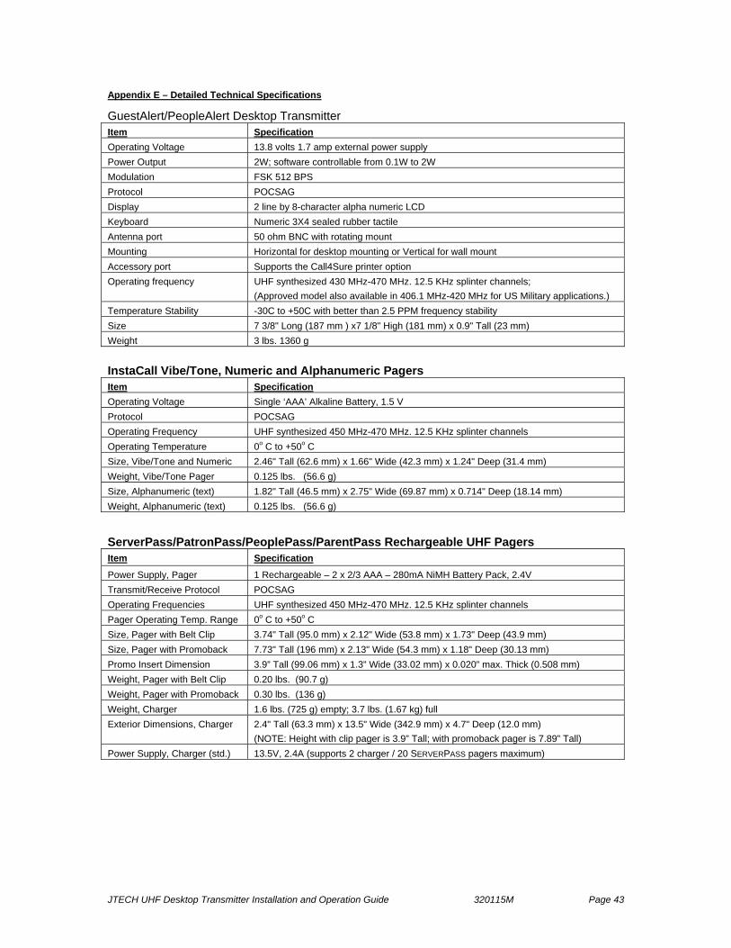
JTECH UHF Desktop Transmitter Installation and Operation Guide 320115M Page 43
Appendix E – Detailed Technical Specifications
GuestAlert/PeopleAlert Desktop Transmitter Item Specification Operating Voltage 13.8 volts 1.7 amp external power supply Power Output 2W; software controllable from 0.1W to 2W Modulation FSK 512 BPS Protocol POCSAG Display 2 line by 8-character alpha numeric LCD Keyboard Numeric 3X4 sealed rubber tactile Antenna port 50 ohm BNC with rotating mount Mounting Horizontal for desktop mounting or Vertical for wall mount Accessory port Supports the Call4Sure printer option Operating frequency UHF synthesized 430 MHz-470 MHz. 12.5 KHz splinter channels;
(Approved model also available in 406.1 MHz-420 MHz for US Military applications.) Temperature Stability -30C to +50C with better than 2.5 PPM frequency stability Size 7 3/8" Long (187 mm ) x7 1/8" High (181 mm) x 0.9" Tall (23 mm) Weight 3 lbs. 1360 g
InstaCall Vibe/Tone, Numeric and Alphanumeric Pagers Item Specification Operating Voltage Single ‘AAA’ Alkaline Battery, 1.5 V Protocol POCSAG Operating Frequency UHF synthesized 450 MHz-470 MHz. 12.5 KHz splinter channels Operating Temperature 0o C to +50o C Size, Vibe/Tone and Numeric 2.46" Tall (62.6 mm) x 1.66" Wide (42.3 mm) x 1.24" Deep (31.4 mm) Weight, Vibe/Tone Pager 0.125 lbs. (56.6 g) Size, Alphanumeric (text) 1.82" Tall (46.5 mm) x 2.75" Wide (69.87 mm) x 0.714" Deep (18.14 mm) Weight, Alphanumeric (text) 0.125 lbs. (56.6 g)
ServerPass/PatronPass/PeoplePass/ParentPass Rechargeable UHF Pagers Item Specification
Power Supply, Pager 1 Rechargeable – 2 x 2/3 AAA – 280mA NiMH Battery Pack, 2.4V Transmit/Receive Protocol POCSAG Operating Frequencies UHF synthesized 450 MHz-470 MHz. 12.5 KHz splinter channels Pager Operating Temp. Range 0o C to +50o C Size, Pager with Belt Clip 3.74" Tall (95.0 mm) x 2.12" Wide (53.8 mm) x 1.73" Deep (43.9 mm) Size, Pager with Promoback 7.73" Tall (196 mm) x 2.13" Wide (54.3 mm) x 1.18" Deep (30.13 mm) Promo Insert Dimension 3.9” Tall (99.06 mm) x 1.3” Wide (33.02 mm) x 0.020” max. Thick (0.508 mm) Weight, Pager with Belt Clip 0.20 lbs. (90.7 g) Weight, Pager with Promoback 0.30 lbs. (136 g) Weight, Charger 1.6 lbs. (725 g) empty; 3.7 lbs. (1.67 kg) full Exterior Dimensions, Charger 2.4" Tall (63.3 mm) x 13.5" Wide (342.9 mm) x 4.7" Deep (12.0 mm)
(NOTE: Height with clip pager is 3.9” Tall; with promoback pager is 7.89” Tall) Power Supply, Charger (std.) 13.5V, 2.4A (supports 2 charger / 20 SERVERPASS pagers maximum)

JTECH UHF Desktop Transmitter Installation and Operation Guide 320115M Page 44
Glowster Pager Item Specification
Operating Voltage 1 Rechargeable – 2 x 2/3 AAA – 280mA NiMH Battery Pack, 2.4V) Protocol POCSAG Operating Frequency UHF synthesized 450 MHz-470 MHz. 12.5 KHz splinter channels Operating Temperature 0o C to +50o C Size, Pager 4 1/4" Tall (108 mm) x 4" Wide (102 mm) x 1 " Deep (25 mm) Size, Pager with Promoback 6 1/4" Tall (159 mm) x 4" Wide (102 mm) x 1 3/4" Deep (44 mm) Promo Insert Dimension 1 5/8” Tall (41 mm) x 3 3/8” Wide (86 mm) x 1/32” max. Thick (0.8 mm) Weight 0.5 lbs. 220 g
CommPass Pager Item Specification
Power Supply, Pager 1 Rechargeable – 2 x 2/3 AAA – 280mA NiMH Battery Pack, 2.4V Transmit/Receive Protocol POCSAG Operating Frequencies UHF synthesized 445 MHz-470 MHz. 12.5 KHz splinter channels.
(Approved models also available in 406.1 MHz-420 MHz for US Military applications.) Pager Operating Temp. Range 0o C to +50o C Exterior Dimensions, Pager 5.4" Tall (137.16 mm) x 2.25" Wide (57.15 mm) x .91" Deep (23.11 mm) Promo Insert Dimension 3.9” Tall (99.06 mm) x 1.3” Wide (33.02 mm) x 0.020” max. Thick (0.508 mm) Weight, Pager 0.25 lbs. (.1134 kg) Weight, Charger 6.78 lbs. (3.08 kg) empty; 11.36 lbs. (5.14 kg) full Exterior Dimensions, Charger 13.0" Tall (325 mm) x 7.0625" Wide (179 mm) x 7.1875" Deep (182 mm) Power Supply, Charger (std.) 13.5V, 2.4A (supports 1 charger / 20 COMMPASS pagers maximum) Power Supply, Charger (large) 13.5V, 7.3A (supports up to 3 chargers / 60 COMMPASS pagers maximum)
JTECH UHF Desktop Transmitter Installation and Operation Guide 320115M Page 45
Service If you need service, dial toll-free 800.321.6221 or 561.997.0772 and select option 6 for JTECH Customer Care. If your problem cannot be solved over the phone by one of our service technicians, we will issue you a return materials authorization (RMA) number for you to send the product in for service. Once your product has been received by JTECH, it will be repaired and returned to you with in the current posted lead-time. This is the standard Repair/Return program and covers all pager products. (In lieu of a phone call, you may also send a fax to 561.995.2260 or e-mail us at “[email protected]”.) As the most critical system component and integral to your business, the system Master Transmitter is covered by our Advance Replacement program. When you receive the replacement, simply place the defective transmitter unit in the same box that it arrived in, attach the return address label to the outside of the box (this label also includes your RMA number) and return it to us. All returned shipment costs are the responsibility of the client. Advance Replacement services are also offered on most pager products for your convenience. Ask your Customer Care Representative about purchasing this value-added service. When return-shipping products to JTECH, we recommend equipment be shipped in a traceable manner for your protection. US Mail is not a recommended method of shipment. Any equipment not received by JTECH Communications within 20 days will be billed to the client at full retail value. There are no charges for repaired equipment within the warranty period other than your shipping costs. There may be an additional charge if, after the item is returned and analyzed, it is determined to be “non-salvageable” - for example, liquid damage, abused or misused. The standard warranty does not cover the replacement of adapters, antennas, pager belt clips, pager promobacks, pager battery doors, user-replaceable rechargeable batteries, pager neck chains, liquid damage to master transmitter and pagers, lightning strikes or other acts of God that could affect the performance of the master transmitter, pagers and peripherals. Check with Customer Care for extended warranty options, as well as the latest charges for repair or replacement of equipment that is out of warranty. Any order returned to JTECH is subject to a restocking fee. Refunds are on product and tax only. JTECH Communications is committed to providing reliable and responsive service to our clients. We believe that our service is the most responsive, comprehensive and cost-effective program in the industry.

JTECH UHF Desktop Transmitter Installation and Operation Guide 320115M Page 46
General Terms and Conditions This offer is subject to the terms and conditions listed below which are binding upon the seller and the buyer under this offer and are hereby incorporated by reference in any subsequent agreement for purchase duly executed between JTECH Communications Inc. Inc. (Seller) and its buyer of goods proposed for sale herein: 1. Price. All prices are F.O.B. point of origin, unless otherwise agreed to in writing by the buyer and seller. Prices quoted are those in effect at the time of quotation and are valid for 30 days from the date of quotation regardless of existence of any written confirmation. Until the proposal price and subsequent purchase price are paid in full, the buyer grants seller a security interest in all of the goods described in this proposal all of the goods described in any resulting contract and buyer agrees to sign on seller's request any required documentation to complete seller's said security interest. 2. Payment Terms. Normal payment terms are C.O.D. unless otherwise set forth in this proposal. Any outstanding balances not paid by the date on which they are due to JTECH Communications Inc. Inc. shall be subject to interest of 1 1/2% per month on the unpaid balance (or the maximum allowable by law whichever is the lesser) as well as rebilling charges together with reasonable attorney's fees and paralegal fees including all such fees in any appeal together with all costs associated with efforts by JTECH Communications Inc. to enforce the terms of this proposal as well as all agreements between the parties. Any discounts offered will be calculated from the date of invoice to the date that payment is received by JTECH Communications Inc. or JTECH Communications Inc.'s agents. Any discount is void if not taken at time of payment of the invoice containing said discount within thirty (30) days of the date on which the goods for which the discount is allowed, have been received by Buyer, its agents or employees. 3. Products. Products are defined as those items listed on this proposal and a subsequent resultant purchase order to JTECH Communications Inc. containing items listed on this proposal. 4. Acceptance. Upon receipt the buyer shall immediately inspect and/or test the products. Unless stated otherwise in writing on the final agreement between the parties, products shall be deemed accepted unless the buyer notifies JTECH Communications Inc. within 5 working days after receipt of shipment of any defect or discrepancy. 5. Transportation. Unless the buyer specifies the method of transportation, JTECH Communications Inc. will use its best judgment in determining the method of transportation. All costs of standard transportation, premium transportation if required through no fault of JTECH, and other costs such as excise taxes, duty, freight forwarding or the like shall be billed to the buyer. 6. Title and Risk of Loss. Title of goods sold, shall pass to buyer at the F.O.B. point.
7. Limited Warranty for material and workmanship. JTECH (Seller) warrants to the buyer that products purchased from JTECH shall be free from defects in material and workmanship under normal use and service. JTECH's obligation under this warranty shall be limited to the repair or exchange of any part or parts which may thus prove defective under normal use and service within one (1) year from date of purchase by the original purchaser, and which our examination shall disclose to our satisfaction to be thus defective. THIS PROPOSAL AND SUBSEQUENT SALE ARE MADE ON THE EXPRESS UNDERSTANDING THAT THERE IS NO IMPLIED WARRANTY THAT THE GOODS SHALL BE MERCHANTABLE OR AN IMPLIED WARRANTY THAT THE GOODS SHALL BE FIT FOR ANY PARTICULAR PURPOSE. THE BUYER ACKNOWLEDGES THAT BUYER IS NOT RELYING ON THE SELLER'S SKILL OR JUDGMENT TO SELECT OR FURNISH GOODS SUITABLE FOR ANY PARTICULAR PURPOSE AND THAT THERE ARE NO WARRANTIES WHICH EXTEND BEYOND THOSE PREVIOUSLY SET FORTH HEREIN. PURCHASER IS DIRECTED NOT TO RELY ON JTECH'S PRODUCTS TO FUNCTION AS AN INTEGRAL PART OF ITS LIFE CARE/LIFE SUPPORT PROCEDURES OR SYSTEMS. JTECH'S PRODUCTS ARE NOT DESIGNED FOR SUCH USE; PARTICULARLY WHEN AN ALLEGATION MAY BE MADE THAT PRODUCT MALFUNCTION CONTRIBUTED TO THE FAILURE TO ADMINISTER A PROPER TREATMENT, PROCEDURE, ACTION, OR MEDICATION. BUYER AGREES TO FULLY PROTECT, DEFEND AND HOLD SELLER HARMLESS FROM CLAIMS OR DAMAGES RESULTING FROM THE USE OF JTECH'S PRODUCTS IN LIFE CARE/LIFE SUPPORT PROCEDURES. Any claim by the buyer for the repair or exchange of goods proposed and of goods actually sold to buyer shall be deemed waived by the buyer unless submitted in writing to JTECH within the earlier of (a) 30 (thirty) days from the date the buyer discovered or by reasonable inspection should have discovered any claimed breach of the foregoing warranty.
8. Damages Based Upon Negligence or Strict Liability. JTECH's obligation based upon any claim of negligence or of strict liability as a result of its delivery of products ordered by Buyer, shall be limited to, at JTECH's option, repairing or replacing the products that are found by JTECH to be defective, or refunding the purchase price of such products. In no event shall JTECH's liability exceed the purchase price of the products which are subject matter of any such claim. JTECH shall not be obligated to make any such refund or replacement until at least thirty (30) days after JTECH has received from Buyer the subject alleged defective product, which will be shipped to JTECH at the buyer's expense.

JTECH UHF Desktop Transmitter Installation and Operation Guide 320115M Page 47
9. Disclaimer of Consequential Damages. In no event shall JTECH be liable for incidental or consequential damages arising out of or in connection with the purchase by Buyer of goods from JTECH including, without limitation, such damages which may be caused by a breach of any obligation or warranty imposed on JTECH under such purchase. Consequential damages shall include without limitation, loss of use, income or profit, or loss sustained as the result of injury to any person, or loss or damage to any property, or loss or damages sustained as the result of work stoppage. Buyer shall indemnify JTECH against all liability, cost, or expense which may be sustained by JTECH due to loss, damage, or injury. IN NO EVENT, SHALL JTECH'S LIABILITY EXCEED THE PURCHASE PRICE OF GOODS.
10. Taxes. Unless specifically provided herein, the price for goods purchased as a result of this proposal does not include sales, use, excise or similar taxes, whether Federal, State or local. Buyer is responsible for all applicable taxes for any goods after title passes to the Buyer at the F.O.B.point. If Buyer is exempt from paying sales taxes, a certificate evidencing such shall be provided to JTECH upon request.
11. Export. Buyer agrees not to directly or indirectly export any Goods purchased from JTECH (whether or not modified by subsequent services) including, but not limited to parts, equipment, software or technical data/documentation without first obtaining the required U.S. Government export license(s). If Buyer intends to export Goods outside the U.S., Buyer shall determine whether an export license is required; and, if so, obtain that license from the U.S. Government. Buyer shall protect, defend and indemnify JTECH from any loss or liability due to Buyer's failure to comply with export regulations. Buyer furthers warrants that the Goods sold to Buyer from JTECH will not be resold, transferred, exported or reused in any way by Buyer in violation of any laws, regulations or export control imposed by the U. S. Government. 12. Delays. Unless specified in writing by JTECH to the contrary, goods in stock shall be shipped immediately upon the signing of a binding purchase agreement. Goods not in stock will be shipped as soon as possible. JTECH will not be liable for any nonperformance of the Agreement resulting from this proposal caused by strikes, fires, disasters, riots, acts of God or other causes or conditions beyond JTECH's reasonable control. In the event of such delay or nonperformance, JTECH may, at its sole option, and without liability, cancel any portion of the Agreement resulting from this proposal and/or extend any date upon which any performance is due. 13. Termination. If Buyer (a) fails to pay any amount owed when due, or (b) assigns or transfers the Agreement subsequently resulting from this proposal without JTECH's prior written consent, or (c) makes an assignment for benefit of creditors, or (d) files or has filed against it, petition for relief under federal or state bankruptcy laws, or (e) breaches any other term or condition of this proposal or resultant contract, JTECH may terminate any portion of the agreement resulting from this proposal in addition to JTECH's other available remedies. If JTECH fails to perform any obligation when due, and if such failure is not remedied within thirty (30) days after receipt of written notice from Buyer, Buyer may terminate any portion of such Agreement. In all other cases, the Agreement resulting from this proposal may be terminated by either party by giving sixty (60) days written notice. Termination of the Agreement, for any reason, shall in no way interfere with the obligation of Buyer to pay all monies payable as of the effective date of termination or which become payable for Goods ordered and delivered after such termination. If such Agreement is terminated by Buyer for any reason other than default by JTECH, Buyer shall be liable immediately thereupon, to pay to JTECH the full contract price for all goods completed by JTECH pursuant to the Agreement and for all work in process at the time of termination. 14. Returns and Cancellations. Buyer may not cancel any order or return any Goods that have been special or custom ordered, custom manufactured or configured, unless specifically agreed to in writing to seller in this proposal and in the subsequent agreement. Returns are subject to a restocking fee which will be due to seller when the goods are received by seller. 15. Patents and Copyrights. In no event shall JTECH be liable for damages arising from infringement of patents or copyrights. In the event that Buyer should be enjoined in any such suit alleging infringement of patent(s) or copyright(s) or proceeding from using any of the Goods purchased pursuant to this proposal and subsequent Agreement, JTECH, at its option, shall either (a) secure termination of the injunction and procure for Buyer the right to use such goods without obligation or liability or (b) replace or modify said Goods with non infringing materials at JTECH's expense and refund the purchase price of the infringing goods to Buyer; provided, however, that in no event shall JTECH be liable for or have any obligations under this paragraph if the alleged infringement is by reason of the specifications provided by Buyer to JTECH under this agreement. The foregoing shall be Buyer's exclusive remedy against JTECH with respect to any alleged patent or Copyright infringement. The sale of goods does not convey any license of copyright under any proprietary or patent rights of any manufacturer. JTECH shall not have any liability if the alleged infringement is based upon the use or application of the Goods in combination with other Goods and Buyer shall protect, defend, and indemnify JTECH therefrom. JTECH disclaims all other liability for infringement of intellectual property rights and further disclaims any liability for incidental or consequential damages arising in connection with such infringement.
16. Manufacturer Liability. In addition to JTECH's limited warranty for materials and workmanship as per section 7 herein, and unless specifically greed to in writing by the manufacturer, JTECH and Buyer, Buyer represents to JTECH and the manufacturer that the Goods sold pursuant to this proposal and the subsequent resultant Agreement incorporating such of the terms of this proposal agreed to by JTECH and buyer do not constitute standard components intended for use by Buyer or JTECH in life support systems, surgical implantation, nuclear facilities, or for any other application in which the failure of the Goods or the product in which the Goods are to be used could create a situation where personal injury or death may occur.

JTECH UHF Desktop Transmitter Installation and Operation Guide 320115M Page 48
17. Credit Terms. All orders and shipments shall at all times be subject to the approval of JTECH's credit department. JTECH reserves the right of declining to make any shipment called for by the contract between seller and buyer whenever, for any reason, there is doubt in JTECH's sole judgment, as to buyer's willingness or ability to pay for the goods ordered on Buyer's solvency and JTECH shall not, in such event, be liable for breach or nonperformance of this Agreement in whole or in part. 18. Packaging. Packaging will be standard commercial package and acceptable to commercial carriers. Special customer packaging will be furnished only when specified and so stated herein and the cost thereof shall have been agreed to by both the Buyer and JTECH in writing. 19. Substituted or Repaired Goods. If substitute additional or repaired goods are purchased by Buyer from JTECH, the terms and conditions of this proposal and resultant Agreement shall be applicable thereto, the same as if such substituted, additional or repaired Goods had been originally purchased hereunder unless specifically stated to the contrary in this proposal or subsequent resultant Agreement. 20. General Conditions. No agent, salesman or other party is authorized to bind JTECH to any agreement, warranty, statement, promise or understanding not expressed herein. The sale of Goods pursuant to this proposal and any subsequent resultant Agreement shall be governed by the laws of the State of Florida. Any notice which is required under the terms of a resultant Agreement shall be in writing and delivered to the address of the party set forth in the Agreement and shall be effective when actually received. The remedies reserved by the parties shall be cumulative and in addition to other remedies provided by law. JTECH shall not be required to proceed with the performance of any obligation under a resultant Agreement so long as Buyer is in default or in breach of any of Buyer's obligations or agreements herein. Any clerical errors are subject to correction. No delay or omission by JTECH in exercising any right or remedy under that agreement shall constitute a waiver of such right or remedy. The waiver, invalidity, or unenforceability of any provision in a resultant Agreement shall not affect the validity of the agreement as a whole or any other provisions herein. An Agreement resulting from this proposal shall be binding upon and shall inure to the benefit of the successors and assigns of Buyer and JTECH. Buyer may not assign or transfer such Agreement in whole or in part without the prior written consent of JTECH. For the purposes of such agreement, the Buyer and JTECH agree, notwithstanding any of the items sold not constituting "goods" as defined in Article 2 of the Uniform Commercial Code as enacted and amended from time to time in the state of Florida, for the purpose of interpreting this proposal or a resultant Agreement all items shall be deemed to be such "goods." Buyer agrees that acceptance of this proposal and receipt of shipment from JTECH pursuant to any resultant Agreement shall constitute acceptance in total of the preceding General Terms and Conditions except as otherwise agree to in writing by the parties thereto.

Got Questions? Need Help? Call JTECH Customer Care at 1-800-321-6221, Option 6.
© 2005 JTECH Communications, Inc. Printed in USA
JTECH Communications Inc. 6413 Congress Ave., Suite 150 Boca Raton, Florida 33487 USA
Toll Free: (800) 321-6221 Phone: (561) 997-0772
Fax: (561) 997-0773 www.jtech.com
Part Number: 320115M