premierwave 2050 enterprise wi-fi iot module integration guide
TRANSCRIPT

Part Number 900-731-R Revision A February 2016
PremierWave 2050 Enterprise Wi-Fi® IoT Module
Integration Guide

PremierWave® 2050 Enterprise Wi-Fi® IoT Module Integration Guide 2
Intellectual Property © 2016 Lantronix, Inc. All rights reserved. No part of the contents of this publication may be transmitted or reproduced in any form or by any means without the written permission of Lantronix.
Lantronix and PremierWave are registered trademarks of Lantronix, Inc. in the United States and other countries.
Patented: http://patents.lantronix.com; additional patents pending.
Wi-Fi is a registered trademark of Wi-Fi Alliance Corporation. Ethertronics is a trademark of Ethertronics, Inc. Exar is a trademark of Exar Integrated Systems Corporation. SEMTECH is a trademark of Semtech Corporation. All other trademarks and trade names are the property of their respective holders.
Contacts Lantronix, Inc. 7535 Irvine Center Drive, Suite 100 Irvine, CA 92618, USA Toll Free: 800-526-8766 Phone: 949-453-3990 Fax: 949-453-3995
Technical Support Online: www.lantronix.com/support
Sales Offices For a current list of our domestic and international sales offices, go to the Lantronix web site at www.lantronix.com/about/contact
Disclaimer All information contained herein is provided “AS IS.” Lantronix undertakes no obligation to update the information in this publication. Lantronix does not make, and specifically disclaims, all warranties of any kind (express, implied or otherwise) regarding title, non-infringement, fitness, quality, accuracy, completeness, usefulness, suitability or performance of the information provided herein. Lantronix shall have no liability whatsoever to any user for any damages, losses and causes of action (whether in contract or in tort or otherwise) in connection with the user’s access or usage of any of the information or content contained herein. The information and specifications contained in this document are subject to change without notice.
This equipment has to be tested and found to comply with the limits for a Class B digital device, pursuant to Part 15 of the FCC Rules. These limits are designed to provide reasonable protection against harmful interference in a residential installation. This equipment generates, uses, and can radiate radio frequency energy and, if not installed and used in accordance with the instructions, may cause harmful interference to radio communications. However, there is no guarantee that interference will not occur in a particular installation.

PremierWave® 2050 Enterprise Wi-Fi® IoT Module Integration Guide 3
If this equipment does cause harmful interference to radio or television reception, which can be determined by turning the equipment off and on, the user is encouraged to try to correct the interference by one of the following measures:
1. Reorient or relocate the receiving antenna.
2. Increase the separation between the equipment and receiver.
3. Connect the equipment into an outlet on a circuit different from that to which the receiver is connected.
4. Consult the dealer or an experienced radio/TV technician for help.
This device complies with Part 15 of the FCC Rules. Operation is subject to the following two conditions: (1) This device may not cause harmful interference, and (2) this device must accept any interference received, including interference that may cause undesired operation.
This device is intended only for OEM Integrators. The OEM integrator should be aware of the following important considerations.
Labeling of the End Product The label on the end product incorporating the PremierWave 2050 module must clearly state that it contains an FCC-approved RF module. Canada and Japan also require a similar statement.
For example, “This product contains RF transmitter ID # (put FCC, IC, CMIIT, and/or Japan module grant numbers here).” The label must include the ID numbers for the regions where the end product is installed. The grant numbers are below.
♦ PremierWave 2050 FCC ID number: R68PW2050
♦ PremierWave 2050 IC ID number: 3867A-PW2050
♦ PremierWave 2050 Japan ID numbers: 201-152843
♦ PremierWave 2050 China SRRC CMIIT ID: 2015AJ6847 (M)
RSS-GEN Sections 7.1.4 and 7.1.5 Statement for Devices with Detachable Antennas
This device has been designed to operate with the antennas listed in the Certificate, and having a maximum gain of 5.5 dBi. Antennas not included in this list or having a gain greater than 5.5 dBi are strictly prohibited for use with this device, unless system level approval is gained. The required antenna impedance is 50 ohms.
To reduce potential radio interference to other users, the antenna type and its gain should be so chosen that the equivalent isotropically radiated power (EIRP) is not more than that required for successful communication.

PremierWave® 2050 Enterprise Wi-Fi® IoT Module Integration Guide 4
Integration Notes This module is authorized under limited module approval specific to mobile host equipment. The antenna must be installed with a 20 cm space maintained between the antenna and users.
The transmitter module may not be co-located with any other transmitter or antenna.
As long as the two conditions above are met, further transmitter testing will not be required. However, the OEM integrator is still responsible for testing their end product for any additional compliance requirements required with this module installed (for example, digital device emission, PC peripheral requirements, etc.)
In the event that these conditions cannot be met (for example certain laptop configurations, general purpose PCMCIA or similar cards, or co-location with another transmitter) and obtaining a separate FCC authorization will be required, then the FCC authorization is no longer considered valid and the FCC ID cannot be used on the final product (including the transmitter).
Changes or modifications to this device not explicitly approved by Lantronix will void the user's authority to operate this device.
Note: With the purchase of any PremierWave 2050 family product, the OEM agrees to an OEM firmware license agreement that grants the OEM a non-exclusive, royalty-free firmware license to use and distribute the binary firmware image provided, only to the extent necessary to use the PremierWave 2050 hardware. For further details, please see the PremierWave 2050 OEM firmware license agreement.
Note: Please refer to the PremierWave 2050 Enterprise Wi-Fi IoT Module Datasheet, available at www.lantronix.com/support/documentation, for the full compliance specification and requirements.
Warranty For details on the Lantronix warranty policy, please go to our Web site at www.lantronix.com/support/warranty.
Revision History Date Rev. Comments February 2016 A Initial document.
For the latest revision of this product document, please check our online documentation at www.lantronix.com/support/documentation.

PremierWave® 2050 Enterprise Wi-Fi® IoT Module Integration Guide 5
Table of Contents
Intellectual Property _________________________________________________________ 2 Contacts __________________________________________________________________ 2 Disclaimer ________________________________________________________________ 2 Labeling of the End Product __________________________________________________ 3 RSS-GEN Sections 7.1.4 and 7.1.5 Statement for Devices with Detachable Antennas ____ 3 Integration Notes ___________________________________________________________ 4 Warranty _________________________________________________________________ 4 Revision History ____________________________________________________________ 4 List of Figures _____________________________________________________________ 6 List of Tables ______________________________________________________________ 6
1: Introduction 7About the Integration Guide ___________________________________________________ 7 Additional Documentation ____________________________________________________ 8
2: Functional Description 9PremierWave 2050 Features __________________________________________________ 9 PremierWave 2050 Block Diagram ____________________________________________ 11 Signal Descriptions ________________________________________________________ 12 Antenna Interface _________________________________________________________ 16 Antenna Placement ________________________________________________________ 18 Serial Interface ___________________________________________________________ 19 Ethernet Interface _________________________________________________________ 21 USB Device Port __________________________________________________________ 23 USB Host Port ____________________________________________________________ 24 LEDs ___________________________________________________________________ 25 General Purpose I/O Pins ___________________________________________________ 25 Reset Pins _______________________________________________________________ 26
3: PCB Footprint and Module Dimensions 27Access CAD Files _________________________________________________________ 27 Reflow Profile Guideline ____________________________________________________ 29 MSD (Moisture Sensitive Device) Control for the Module ___________________________ 30 Product Information Label ___________________________________________________ 31 Evaluation Board Schematic _________________________________________________ 32

PremierWave® 2050 Enterprise Wi-Fi® IoT Module Integration Guide 6
List of Figures Figure 2-1 PremierWave 2050 Dimensions and Views ____________________________ 10 Figure 2-2 PremierWave 2050 Block Diagram ___________________________________ 11 Figure 2-3 PremierWave 2050 Pin Locations ____________________________________ 15 Figure 2-4 Reverse-SMA to U.FL (Long) (Lantronix Part Number 500-180-R-ACC) ______ 17 Figure 2-5 U.FL to U.FL Cable (Lantronix Part Number 500-181-R-ACC) _____________ 17 Figure 2-6 Reverse-SMA to U.FL (short) (Lantronix Part Number 500-182-R-ACC) ______ 17 Figure 2-7 Module with Chip Antenna Board Edge Mounting _______________________ 18 Figure 2-8 Serial Port Example ______________________________________________ 20 Figure 2-9 Ethernet Connections to an External 10/100 RJ45 Magnetic Jack (J5) _______ 22 Figure 2-10 USB Device Interface Example (PremierWave 2050 Wi-Fi only) ___________ 23 Figure 2-11 USB Host Interface Connections ___________________________________ 24 Figure 2-12 Recommended Use of SHDN Signal to Shut Off External Power Rail _______ 26 Figure 3-1 PremierWave 2050 Module Dimensions_______________________________ 27 Figure 3-2 PremierWave 2050 Recommended Footprint __________________________ 28 Figure 3-3 Recommended Reflow Profile ______________________________________ 30 Figure 3-4 PremierWave 2050 Product Label ____________________________________ 31 Figure 3-5 Evaluation Board Schematic (1 of 7) _________________________________ 32 Figure 3-6 Evaluation Board Schematic (2 of 7) _________________________________ 33 Figure 3-7 Evaluation Board Schematic (3 of 7) _________________________________ 34 Figure 3-8 Evaluation Board Schematic (4 of 7) _________________________________ 35 Figure 3-9 Evaluation Board Schematic (5 of 7) _________________________________ 36 Figure 3-10 Evaluation Board Schematic (6 of 7) ________________________________ 37 Figure 3-11 Evaluation Board Schematic (7 of 7) ________________________________ 38
List of Tables Table 1-1 PremierWave 2050 Integration Guide Sections ___________________________ 7 Table 2-1 PremierWave 2050 Part Numbers _____________________________________ 9 Table 2-2 PremierWave 2050 PCB Interface Signals _____________________________ 12 Table 2-3 PremierWave 2050 Wi-Fi On Module Antenna __________________________ 16 Table 2-4 PremierWave 2050 Wi-Fi External Antenna Options via On Module U.FL _____ 16 Table 2-5 PremierWave 2050 Serial Port Signals ________________________________ 19 Table 2-6 Example RS232 Connections (Serial Transceiver Required) _______________ 20 Table 2-7 Example RS422/485 Connections (Serial Transceiver Required) ____________ 21 Table 2-8 Ethernet Port Signals ______________________________________________ 22 Table 2-9 USB Device Port Signals ___________________________________________ 23 Table 2-10 USB Host Port Signals ____________________________________________ 24 Table 2-11 PremierWave 2050 Wi-Fi Status LED Output Signals ____________________ 25 Table 2-12 Ethernet Interface PremierWave 2050 Serial Port Signals ________________ 25 Table 2-13 PremierWave 2050 Reset Signals ___________________________________ 26

PremierWave® 2050 Enterprise Wi-Fi® IoT Module Integration Guide 7
1: Introduction
About the Integration Guide This user guide provides the information needed to integrate the Lantronix® PremierWave® 2050 family of products into customer-printed circuit boards. This manual is intended for engineers responsible for integrating the PremierWave 2050 enterprise Wi-Fi® IoT module into their product. This document provides instruction for connecting to the various module pin function groups as well as general module placement and mounting. For detailed technical and compliance specifications please refer to the PremierWave 2050 Enterprise Wi-Fi IoT Module Datasheet available at www.lantronix.com/support/documentation.
The table below describes the integration guide sections.
Table 1-1 PremierWave 2050 Integration Guide Sections
Section Description PremierWave 2050 Features Provides an overview of the module functions and mechanical drawing PremierWave 2050 Block Diagram
Shows the module functional blocks
Signal Descriptions Provides signal descriptions and pinout information Antenna Interface Lists the antennas pre-certified for use with the module Antenna Placement Provides a general recommendation for antenna placement Using the RF1 Signal Pin This section is reserved for a future off module antenna connection
option Serial Interface Provides an example on how to connect the unit to external
RS232/485/422 networks Ethernet Interface Gives an example on how to connect the module Ethernet USB Device Port Provides an example on how to connect the unit up as a USB device
port USB Host Port Provides an example on how to connect the module USB host ports LEDs Describes the module LED connections General Purpose IO Pins Describes the module GPIO connections Reset Pins Describes the module RESET, DEFAULT, and WAKE pins Mounting Instructions and PCB Footprint
Provides the module PCB footprint and solder profile
Product Information Label Provides an image and description of the unit label contents Evaluation Board Schematic Provides the PremierWave 2050 evaluation board schematic.

1: Introduction
PremierWave® 2050 Enterprise Wi-Fi® IoT Module Integration Guide 8
Additional Documentation Visit the Lantronix web site at www.lantronix.com/support/documentation for the latest documentation and the following additional documentation.
Document Description PremierWave 2050 Enterprise Wi-Fi IoT Module Datasheet
Provides a unit description and all technical and compliance specifications for the module
PremierWave 2050 Enterprise Wi-Fi IoT Module User Guide
Provides information needed to configure, use, and update the PremierWave 2050 firmware.
PremierWave 2050 Enterprise Wi-Fi IoT Module Evaluation Kit Quick Start Guide
Provides the steps for getting the PremierWave 2050 and PremierWave 2050 evaluation kit up and running.
PremierWave 2050 Enterprise Wi-Fi IoT Module Evaluation Kit User Guide
Provides a detailed description of the PremierWave 2050 evaluation kit hardware
Notification Soldering Profile and Washing
Provides guidance in developing a manufacturing assembly process for various Lantronix embedded products.

PremierWave® 2050 Enterprise Wi-Fi® IoT Module Integration Guide 9
2: Functional Description Designed for quick integration with minimal engineering effort, the chip-sized PremierWave 2050 module provides simplicity and flexibility making it the easiest and fastest networking-enabling module on the market.
PremierWave 2050 modules are extremely compact networking solutions that enable Ethernet or wireless connectivity on virtually any device with a serial interface. The included industry-proven Lantronix module application and full IP stack allow seamless remote access to device data simplifying design integration while providing robust connectivity.
The PremierWave 2050 modules can be utilized in designs typically intended for chip solutions. A key difference with the PremierWave 2050 module is that there is virtually no need to write a single line of code, translating to a much lower development cost and faster time-to-market.
Table 2-1 PremierWave 2050 Part Numbers
Part Number Description
PW205010001B PremierWave 2050, 802.11ac enterprise Wi-Fi module, dual U.FL, ind. temp, Bulk
PW205020001B PremierWave 2050, 802.11ac enterprise Wi-Fi module, chip ant +U.FL, ind. temp, Bulk
PW205010001S PremierWave 2050, 802.11ac enterprise Wi-Fi module, dual U.FL, ind. temp, Sample
PW205020001S PremierWave 2050, 802.11ac enterprise Wi-Fi module, chip ant + U.FL, ind. temp, Sample
PWGG2051000K PremierWave 2050 evaluation Kit, 802.11ac enterprise Wi-Fi module, dual U.FL
PWGG2052000K PremierWave 2050 evaluation kit, 802.11ac enterprise Wi-Fi module, chip ant
PremierWave 2050 Features The PremierWave 2050 module is built around a 400 Mhz ARM9 processor with 32 MB of DDR2 DRAM and 128 MB of embedded flash memory. Network connections are provided by a dual band 802.11 ac/b/g/n WLAN radio and 10/100Mbps Ethernet MAC and PHY.
The PremierWave 2050 module also supports the following:
400 Mhz ARM9 CPU
32 MB DDR2 DRAM
128 MB NAND Flash
802.11 ac/bgn wireless with option for on module antenna or on module U.FL
On module 10/100 Mbps Ethernet MAC/PHY. External magnetic and RJ45 required.
One USB 2.0 high speed host/device interface.

2: Functional Description
PremierWave® 2050 Enterprise Wi-Fi® IoT Module Integration Guide 10
♦ One USB 2.0 high speed host only port
♦ One USB 2.0 full speed host only port
♦ Two 3.3V serial interface
♦ 13 configurable I/O pins
♦ Power supply filters
♦ Reset circuit
♦ Integrated wake up and shutdown for sleep and standby states
♦ Interface for connection to an external JTAG software debugger.
♦ Dedicated two wire serial port for debug
The PremierWave 2050 module requires +5V DC power and is designed to operate in an extended temperature range. (See the PremierWave 2050 Enterprise Wi-Fi IoT Module Datasheet available at www.lantronix.com/support/documentation for all technical specifications.)
Figure 2-1 PremierWave 2050 Dimensions and Views

2: Functional Description
PremierWave® 2050 Enterprise Wi-Fi® IoT Module Integration Guide 11
PremierWave 2050 Block Diagram The following drawing is a block diagram of the PremierWave 2050 module showing the relationships of the components.
Figure 2-2 PremierWave 2050 Block Diagram
2: Functional Description
PremierWave® 2050 Enterprise Wi-Fi® IoT Module Integration Guide 12
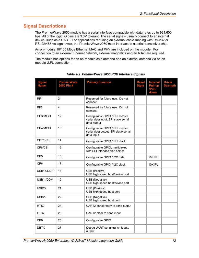
Signal Descriptions The PremierWave 2050 module has a serial interface compatible with data rates up to 921,600 bps. All of the logic IO pins are 3.3V tolerant. The serial signals usually connect to an internal device, such as a UART. For applications requiring an external cable running with RS-232 or RS422/485 voltage levels, the PremierWave 2050 must interface to a serial transceiver chip.
An on-module 10/100 Mbps Ethernet MAC and PHY are included on the module. For connection to an external Ethernet network, external magnetics and an RJ45 are required.
The module has options for an on-module chip antenna and an external antenna via an on-module U.FL connection.
Table 2-2 PremierWave 2050 PCB Interface Signals
Signal Name
PremierWave 2050 Pin #
Primary Function Reset State
Internal Pull-up /Pull-down
Driver Strength
RF1 2 Reserved for future use. Do not connect
RF2 4 Reserved for future use. Do not connect
CP3/MISO 12 Configurable GPIO / SPI master serial data input, SPI slave serial data output
CP4/MOSI 13 Configurable GPIO / SPI master serial data output, SPI slave serial data input
CP7/SCK 14 Configurable GPIO / SPI clock
CP8/CS 15 Configurable GPIO, multiplexed with SPI interface chip select
CP5 16 Configurable GPIO / I2C data 10K PU
CP6 17 Configurable GPIO / I2C clock 10K PU
USB1+/DDP 18 USB (Positive) USB high speed host/device port
USB1-/DDM 19 USB (Negative) USB high speed host/device port
USB2+ 21 USB (Positive) USB high speed host port
USB2- 22 USB (Negative) USB high speed host port
RTS2 24 UART2 serial ready to send output
CTS2 25 UART2 clear to send input
CP9 26 Configurable GPIO
DBTX 27 Debug UART serial transmit data output

2: Functional Description
PremierWave® 2050 Enterprise Wi-Fi® IoT Module Integration Guide 13
Signal Name
PremierWave 2050 Pin #
Primary Function Reset State
Internal Pull-up /Pull-down
Driver Strength
DBRX 28 Debug UART serial receive data input
10K PU
ETXP (ETH1+)
34 Ethernet TX (Positive) Future Gbit pair 1 (pos)
ETXM (ETH1-)
35 Ethernet TX (Negative) Future Gbit pair 1 (net)
TXCT (ECT1)_
37 Center tap connection for Ethernet TX pair
RXCT (ECT2)
38 Center tap connection for Ethernet RX pair
ERXP (ETH2+)
40 Ethernet RX (Positive) Future Gbit pair 2 (pos)
ERXM (ETH2-)
41 Ethernet RX (Negative) Future Gbit pair 2 (neg)
ETH3+ 43 Reserved for future Gbit Ethernet pair 3 (Positive)
ETH3- 44 Reserved for future Gbit Ethernet pair 3 (Negative)
ETH4+ 46 Reserved for future Gbit Ethernet pair 4 (Positive)
ETH4- 47 Reserved for future Gbit Ethernet pair 4 (Negative)
ECT3 49 Reserved for future Gbit center tap 3 connection
ECT4 50 Reserved for future Gbit center tap 4 connection
USB3+ 52 USB (Positive) USB full speed host port
USB3- 53 USB (Negative) USB full speed host port
SPEED_LED 56 Ethernet speed LED, active low for 100 Mbps
CP13 57 Configurable GPIO
CP12 58 Configurable GPIO
CP11 59 Configurable GPIO
CP10 60 Configurable GPIO
WAKE 65 CPU wake up input. Module wakes from low power state on a rising edge
100K PU
DEFAULT# 66 Unit reset to default, active low. Drive low for xx seconds to reset unit to default settings.

2: Functional Description
PremierWave® 2050 Enterprise Wi-Fi® IoT Module Integration Guide 14
Signal Name
PremierWave 2050 Pin #
Primary Function Reset State
Internal Pull-up /Pull-down
Driver Strength
SYS_LED 67 System status LED, active high
CP2/INT 68 Configurable GPIO / SPI interrupt external interrupt input
CP1 71 Configurable GPIO
LINK_ACT 72 Ethernet link/activity LED active low for link. toggle for activity.
WLAN LED 73 LED function for WLAN link indication, active low
RESET# 77 Unit hardware reset, active low. Drive low to reboot unit 35K PU
RXD2 78 UART2 serial receive data input
TXD2 79 UART2 serial transmit data output
CTS1 80 UART1 clear to send input
RTS1 81 UART1 serial ready to send output
RXD1 82 UART1 Serial receive data input
TXD1 83 UART1 serial transmit data output
SHDN 88 Indicates when module is in standby state. Use to power off external devices
RF1_CTL 97 Reserved for future use. Do not connect
TRST 100 TRST signal for external debugger
TDO 101 TDO signal for external debugger
TDI 104 TDI signal for external debugger
TCK 105 TCK signal for external debugger
TMS 106 TMS signal for external debugger
VCC 29,30,31 5V power input
GND 1,3,5,20,23,32, 33,36,39,42,45, 48,51,54,55,61, 64,84,86,87,94, 95,96,98,99,102, 103,107,108,109,
Signal ground

2: Functional Description
PremierWave® 2050 Enterprise Wi-Fi® IoT Module Integration Guide 15
Signal Name
PremierWave 2050 Pin #
Primary Function Reset State
Internal Pull-up /Pull-down
Driver Strength
110,111,112,113, 114,115,116,117, 118,119,120,121, 122,123,124
RSVD 2,4,6,7,8,9,10,11, 43,44,46,47,49,50, 62,63,69,70,74, 75,76,85,89,90, 91,92,93,
Reserved for future use. Leave disconnected.
Note1: The current module supports 10/100 Mbps Ethernet. Additional pins have been called out for a future Gigabit Ethernet module. Note2: The logic IO pins are 3.3V tolerant. Note3: Pins 109 to 124 are the large ground pads under the module. These pads should be connected to ground. These pads also provide thermal relief for the module. It is recommended that multiple vias for each pad be used to connect the ground pads to the ground plane.
Figure 2-3 PremierWave 2050 Pin Locations
Note: Pins 109 to 124 are the large pads under the module. Pins 109 to 124 should be connected to GND. The pads in yellow are for future module revisions and should be left disconnected.
108 107 106 105 104 103 102 101 100 99 98 97 96 95 94 93 92 91 90 89 88 871 GND GND GND TMS TCK TDI GND GND TDO TRST GND GND RF1_CTL GND GND GND VCC2 VCC2 VCC2 VCC2 VCC2 SHDN GND GND 862 RF1 RF3/GPS 853 GND GND 844 RF2 TXD1 835 GND RXD1 826 SDCK RTS1 817 SDCMD CTS1 808 SDIO0 TXD2 799 SDIO1 RXD2 78
10 SDIO2 RESET# 7711 SDIO3 VCC 7612 CP3/MISO VCC 7513 CP4/MOSI VCC 7414 CP7/SCK LED0/LNK 7315 CP8/CS LED1/ACT 7216 CP5/I2CDATA CP1 7117 CP6/I2CCLK SPARE1 7018 USB+ SPARE2 6919 USB- CP2/INT 6820 GND SYS_LED 6721 USB2+ DEFAULT# 6622 USB2- WAKE 6523 GND GND 6424 RTS2 ADC1 6325 CTS2 ADC2 6226 CP9 GND 6127 DBTX CP10/TXD3 6028 DBRX CP11/RXD3 5929 VCC3 CP12/RTS3 5830 VCC3 CP13/CTS3 5731 VCC3 SPEED LED 5632 GND GND 55
GND ETX+ ETX- GND TXCT RXCT GND ERX+ ERX- GND ETH3+ ETH3- GND ETH4+ ETH4- GND ECT3 ECT4 GND USB3+ USB3- GND33 34 35 36 37 38 39 40 41 42 43 44 45 46 47 48 49 50 51 52 53 54
PremierWave 2050 Module
PCB Strip Antenna Area

2: Functional Description
PremierWave® 2050 Enterprise Wi-Fi® IoT Module Integration Guide 16
Antenna Interface The PremierWave 2050 module has been certified using the external antennas listed below. Per FCC guidelines, the PremierWave 2050 Wi-Fi certification remains valid if using an antenna of similar type to the antennas below. If using an antenna of similar type to one of the antennas below, but from a different manufacturer part number the antenna gain must be equal to or less than specified in the table. Refer to the PremierWave 2050 Enterprise Wi-Fi IoT Module Datasheet, available at www.lantronix.com/support/documentation, for full compliance instructions and information. Consult with your certification lab for more details.
Table 2-3 PremierWave 2050 Wi-Fi On Module Antenna
Antenna Type
Peak Gain Typical
Lantronix Part Number
Vendor Vendor Part Number
Approved Region
Ceramic Antenna
2.17dBi, 2.4 GHz to 2.5 GHz 2.74 dBi, 4.9 GHz to 5.8 GHz
N/A N/A N/A FCC, IC, EU, AUS/NZS, JPN, China, Mexico
Table 2-4 PremierWave 2050 Wi-Fi External Antenna Options via On Module U.FL
Antenna Type Peak Gain Typical
Lantronix Part Number
Vendor Vendor Part Number
Approved Region
PCB Strip Antenna with 50 mm cable to U.FL connector With tape backing
2.5dBi, 2.39 GHz to 2.49 GHz 5 dBi, 4.9 GHz to 5.9 GHz
XPW100A003-01-B 50 piece bulk pack
Ethertronics® 1001077 FCC, IC, EU, AUS/NZS, JPN, China, Mexico
PCB Strip Antenna with 50 mm cable to U.FL connector Without tape backing
2.5dBi, 2.39 GHz to 2.49 GHz 5dBi, 4.9Ghz to 5.9Ghz
Ethertronics 1000668 FCC, IC, EU, AUS/NZS, JPN, China, Mexico
Swivel type antenna, with RP-SMA(M) connector
2 dBi, 2.4 GHz to 2.5 GHz, 2 dBi, 5.15 GHz to 5.85 GHz
930-033-R-ACC 50 piece bulk pack
Wanshih WSS002 FCC, IC, EU, AUS/NZS, JPN, China, Mexico
Swivel type antenna, with RP-SMA(M) connector
3.8 dBi, 2.4Ghz to 2.5Ghz, 5.5 dBi, 4.9 GHz to 5.8Ghz
Taoglas GW.71.5153 (Not for EU use)
FCC, IC, AUS/NZS, JPN, China, Mexico
Note: The PCB strip antenna is available from Ethertronics with or without adhesive tape backing for mounting to a plastic case. The antennas Lantronix supplies include an adhesive backing. For the component without tape backing a non-conductive double sided adhesive tape can be used to fix the antenna in place. The Ethertronics part numbers listed above come with a 50 mm U.FL cable attached to the PCB strip antenna. The 50 mm cable length is the minimum allowed cable length for use with the PremierWave 2050 module. For similar PCB strip antennas with longer cables consult with Ethertronics (www.ethertronics.com).
Lantronix provides a U.FL to Reverse SMA antenna cable in with the evaluation board and sample kits for development work. These cables can be purchased from Lantronix for production or supplied by an RF cable manufacturer. External antennas can be purchased from an antenna vendor. Components for cable design should be selected for low loss over the entire 2.4 GHz to 5.9 GHz signal range. The cable target impedance should be 50 ohms.

2: Functional Description
PremierWave® 2050 Enterprise Wi-Fi® IoT Module Integration Guide 17
Figure 2-4 Reverse-SMA to U.FL (Long) (Lantronix Part Number 500-180-R-ACC)
Figure 2-5 U.FL to U.FL Cable (Lantronix Part Number 500-181-R-ACC)
Figure 2-6 Reverse-SMA to U.FL (short) (Lantronix Part Number 500-182-R-ACC)

2: Functional Description
PremierWave® 2050 Enterprise Wi-Fi® IoT Module Integration Guide 18
Antenna Placement When designing the PremierWave 2050 module to a mating board, it is important to consider the final installation of the module and its location with respect to connecting access points. The antenna should be placed so that it has as clear as possible path to the connecting access point for maximum range. Avoid placing the antenna such that it is blocked by metal walls or ground planes of adjacent circuit boards.
When using the on board chip antenna it is recommended to place the module such that the antenna region is along the edge of the board or extending outward from the edge of the board. The area under the chip antenna region should be voided of all signals and planes
See the figure images below showing recommended placement with the module chip antenna.
Figure 2-7 Module with Chip Antenna Board Edge Mounting
Note: The chip antenna region of the module shown in red above is at the top edge of the PCB. The area in red should be voided to optimize antenna performance.
Edge of PCB
Void region in red 6mmx23mm

2: Functional Description
PremierWave® 2050 Enterprise Wi-Fi® IoT Module Integration Guide 19
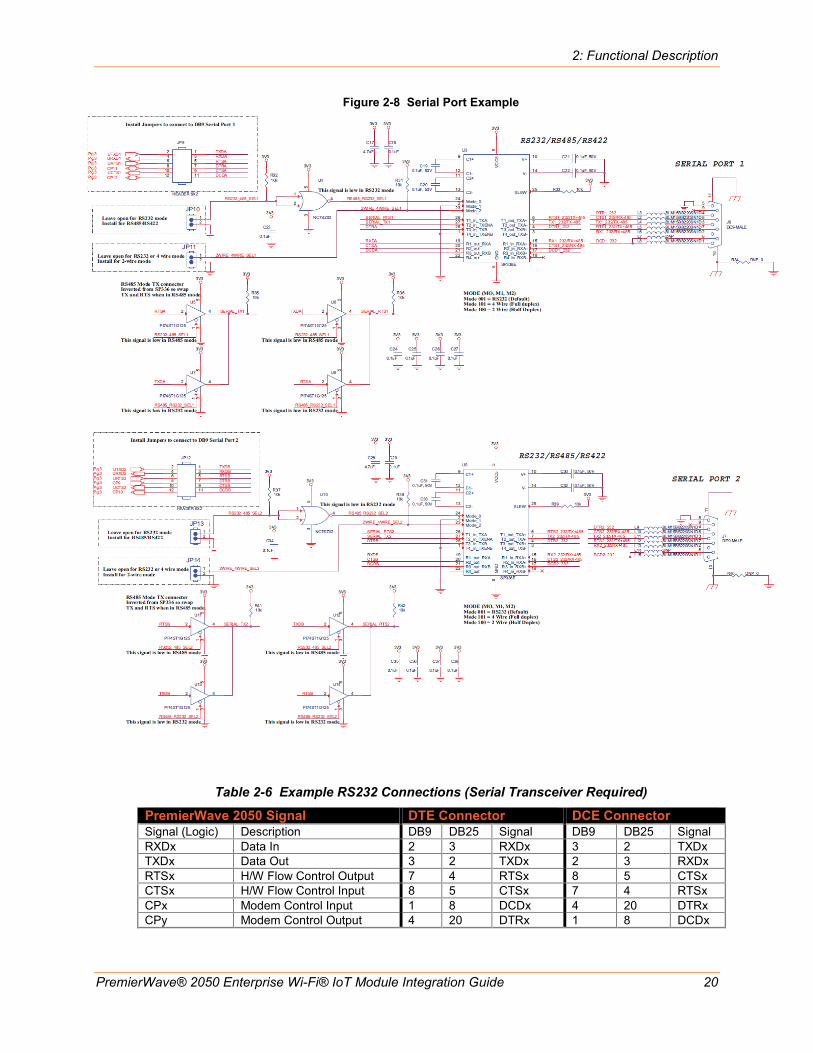
Serial Interface The PremierWave 2050 modules has two external serial interfaces. The signal levels on the serial interface are 3.3V tolerant. The serial interfaces require an external transceiver in order to connect to external RS232, RS485, or RS422 networks. The signals of the Serial Ports may be connected as shown in the reference schematic below. The transceiver shown in the reference schematic is of type Exar, part number SP336. This transceiver is a multiprotocol RS232, RS485, RS422 transceiver. Single protocol transceivers may be used as required. The PremierWave 2050 interface may also be directly connected to the UART interface of an external CPU.
Table 2-5 PremierWave 2050 Serial Port Signals
Signal Module Pin Description TXD1 83 Serial transmit data output RTS1 81 Serial ready-to-send / serial transmit enable output RXD1 82 Serial receive data input CTS1 80 Serial clear-to-send input TXD2 79 Serial transmit data output 2 RTS2 24 Serial ready-to-send / serial transmit enable output RXD2 78 Serial receive data input 2 CTS2 25 Serial clear-to-send input
2: Functional Description
PremierWave® 2050 Enterprise Wi-Fi® IoT Module Integration Guide 20
Figure 2-8 Serial Port Example
Table 2-6 Example RS232 Connections (Serial Transceiver Required)
PremierWave 2050 Signal DTE Connector DCE Connector Signal (Logic) Description DB9 DB25 Signal DB9 DB25 Signal RXDx Data In 2 3 RXDx 3 2 TXDx TXDx Data Out 3 2 TXDx 2 3 RXDx RTSx H/W Flow Control Output 7 4 RTSx 8 5 CTSx CTSx H/W Flow Control Input 8 5 CTSx 7 4 RTSx CPx Modem Control Input 1 8 DCDx 4 20 DTRx CPy Modem Control Output 4 20 DTRx 1 8 DCDx

2: Functional Description
PremierWave® 2050 Enterprise Wi-Fi® IoT Module Integration Guide 21
Table 2-7 Example RS422/485 Connections (Serial Transceiver Required)
PremierWave 2050 Signal (logic)
Description RS485 Signal
DB25 4 Wire
DB25 2 Wire
DB9 4 wire
DB9 2 wire
TXDx Data Out TX+485 14 14 7 7 TXDx Data Out TX-485 15 15 3 3 RXDx Data In RX+485 21 14 2 7 RXDx Data In RX-485 22 15 8 3 RTSx TX Enable CPx RS485 Select CPy RS485 2-wire
Note: The IO pins for PremierWave 2050 module are set to floating input on power up until configured by unit firmware. An external 100K ohm pull-up may be required on the serial transmit signal to prevent downstream UART devices from detecting false characters on initial power up.
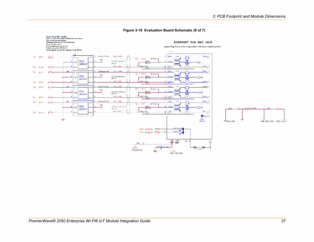
Ethernet Interface The unit provides a 10/100 Mbps Ethernet interface for connection to an external network through external magnetics and an external RJ45. The figure below shows the Ethernet connections to a 10/100 Ethernet RJ45 Jack with Magnetics, J5 in the figure. The RJ45 Magnetic Jack is Belfuse part number 08B0-1D1T-06-F.
The Ethernet differential pair signals, ERXM/ERXP and ETXM/ETXP should be routed as 100-ohm differential pairs on a layer next to the signal ground plane. The use of vias on these signals should be minimized. Center tap signals RXCT and TXCT should be routed with at least 20 mil trace thickness. The area underneath the RJ45 magnetic jack should be void of all signals and planes. The connector shield should be connected to chassis. It is recommended that 1206 resistor pads from chassis ground to signal ground be placed next to each of the shield tabs. The resistor pads allow for 0 ohm jumper, ferrite beads, or decoupling caps to be installed as needed for EMI/EMC improvement.
The Ethernet LED signals should be routed to discrete LEDs or to the LED pins on the RJ45 through 220 ohm or larger resistors. The LED signals are active low.
Also shown in the figure is an optional active choke that can be used to improve ESD, EFT, and EMI/EMC performance in harsh environments. The device is shown as U22 in the figure and is Akros part number AS1602. This device features route through pin assignments allowing for the Ethernet differential signal pairs to be routed without altering the trace impedance or adding vias. Due to this routing the device could be installed or depopulated as needed. Lantronix has performed all certification to FCC Class B without U22 populated.
The Ethernet signals may be left disconnected if unused.
See the Lantronix app note, How to Connect a Lantronix Embedded Module to a Wired Ethernet Port for more details on Ethernet connection and routing, http://www.lantronix.com/pdf/appnotes/Connect-LTRX-Embed-Module-to-Wired-Ethernet_AN.pdf.

2: Functional Description
PremierWave® 2050 Enterprise Wi-Fi® IoT Module Integration Guide 22
Table 2-8 Ethernet Port Signals
Pin Name Description PremierWave 2050 Pins
Signal Requirement RJ45 MagJack Belfuse, 08B0-1D1T-06-F Pin assignment
ERXM Ethernet Receive Negative signal. 41 100 ohm differential pair with ERXP
5
EXRP Ethernet Receive Positive signal. 40 100 ohm differential pair with ERXM
4
ETXM Ethernet Transmit Negative signal.
35 100 ohm differential pair with ETXP
3
ETXP Ethernet Transmit Positive signal. 34 100 ohm differential pair with ETXM
2
RXCT Center tap for receive pair. 38 Route > 20 mil width 6 TXCT Center tap for transmit pair 37 Route > 20 mil width 1 Chassis Unit chassis - RJ45 connector shield Shield tabs E_LNKACT Link / activity LED. Active low.
Solid for link, blink for activity. 72 Route to LED cathode
through 220 ohm or greater.
9
E_SPEED Link Speed Active low for 100Mbps, Off (high) for 10Mbps.
56 Route to LED cathode through 220 ohm or greater.
7
3V3 3.3 V power 3V3 3.3V power, connect to LED anodes.
8, 10
Figure 2-9 Ethernet Connections to an External 10/100 RJ45 Magnetic Jack (J5)

2: Functional Description
PremierWave® 2050 Enterprise Wi-Fi® IoT Module Integration Guide 23
USB Device Port The PremierWave 2050 module has one USB 2.0 device port interface for connection to an upstream USB device. The port consists of a differential pair, signals DDP and DDM. These signals should be routed as a 90 ohm differential pair on a signal layer next to the signal ground plane. The use of vias should be minimized on these signals. The USB signals can be connected to a USB Mini Type B USB port or directly to an IC with a USB host port. If connecting to an external port that is user accessible it is recommended to add a TVS diode array to the signal nets for ESD protection. The ESD array shown in the figure is of type SEMTECH RCIamp0502A. This device features through pin routing to minimize trace impedance changes and simplify routing. The footprint for the TVS array can be added to the PCB and the part can be depopulated if it is not needed. It is recommended that the power drawn off the USB Mini Type B connector be limited to less than 500 mA per USB requirements. If the USB device port is unused the DDP and DDM pins may be left disconnected.
Table 2-9 USB Device Port Signals
Pin Name Description Module Pins Signal Requirement Mini Type B USB Device Connector Pin
USB+/DDP USB Device Port Positive pin
18 Route as 90 ohm differential pair with DDM signal
3
USB-/DDM USB Device Port Negative pin
19 Route as 90 ohm differential pair with DDP signal
2
5V 5V power from USB cable
Current limit to 500 mA per port
1
Ground Signal Ground Ground Ground plane 5
Figure 2-10 USB Device Interface Example (PremierWave 2050 Wi-Fi only)

2: Functional Description
PremierWave® 2050 Enterprise Wi-Fi® IoT Module Integration Guide 24
USB Host Port The PremierWave 2050 module has two USB 2.0 host port interfaces for connection to downstream USB devices. Each port consists of a differential pair. Port USB 2 is a high speed port and port USB 3 is a full speed port. These signals should be routed as 90 ohm differential pairs on a signal layer next to the signal ground plane. The use of vias should be minimized on these signals. The USB signals can be connected to a USB type A dual USB port as shown in the figure below or directly to an IC with a USB device port. If connecting to an external port that is user accessible it is recommended to add a TVS diode array to the signal nets for ESD protection. The ESD array shown in the figure is of type NXP, IP4234CZ6. If connecting to an off board device that needs power add a USB power switch to current limit the 5V power connection at the connector. USB requires that each port be limited to 500 mA maximum sustained current. If using the USB host ports the end system must take into account the amount of power consumed by the PremierWave 2050 module and each USB device connected to the host ports. The schematic below shows how to connect 5V to a USB host connector using an ST, STMPS2151 power distribution switch. The USB host port 5V power is not provided by the PremierWave 2050 module. If the USB host ports are unused their pins may be left disconnected.
Table 2-10 USB Host Port Signals
Pin Name
Description PremierWave 2050 Pins
Signal Requirement
Type A USB Host connector pin
USB2+/HHSDPB USB HS Host Port A Positive pin
21 Route as 90 ohm differential pair
B3
USB2-/HHSDPM USB HS Host Port A Negative pin
22 Route as 90 ohm differential pair
B2
USB3+/HFSDPC USB FS Host Port B Positive pin
52 Route as 90 ohm differential pair
A3
USB3-/HFSDMC USB FS Host Port B Negative pin
53 Route as 90 ohm differential pair
A2
5V(User supplied)
5V power for USB connector
Current limit to 500 mA per port
A1, B1
Ground Signal Ground Ground Ground plane A4, B4
Figure 2-11 USB Host Interface Connections

2: Functional Description
PremierWave® 2050 Enterprise Wi-Fi® IoT Module Integration Guide 25
LEDs The PremierWave 2050 module contains several external signals that are intended to drive external status LEDs. The LEDs are listed below. The signals may be connected as shown in the reference schematic figure below.
Note: The System LED usually remains on. When the Default button is pressed for 5-6 seconds, the System LED starts blinking every second to indicate the default button can be released to complete resetting the unit to factory default. The unit reboots after release of the Default button. A lit WLAN LED indicates the STA interface is associated with an access point.
Table 2-11 PremierWave 2050 Wi-Fi Status LED Output Signals
Signal Pin Description WI-FI LED 73 Wi-Fi Status LED, active low SYS_LED 67 System status LED, active high ETH SPEED 56 Ethernet 100Mbps ON (Active low), 10Mbps OFF ETH LINK/ACT 72 Ethernet link ON (Active low)
Ethernet activity Blink (toggle)
General Purpose I/O Pins PremierWave 2050 module contains 13 pins which may be used as configurable inputs or outputs. Listed below are the configurable I/O pins. These pins are 3.3V tolerant.
Table 2-12 Ethernet Interface PremierWave 2050 Serial Port Signals
Signal Pin Description PremierWave 2050
Reset State
CP1 71 Configurable I/O Input CP2/INT 68 Configurable I/O-SPI interrupt input Input CP3 12 Configurable I/O- SPI MISO Input CP4 13 Configurable I/O-SPI MOSI Input CP5 16 Configurable I/O Input CP6 17 Configurable I/O Input CP7 14 Configurable I/O-SPI Clock Input CP8 15 Configurable I/O-SPI Chip Select Input CP9 26 Configurable I/O Input CP10 60 Configurable I/O Input CP11 59 Configurable I/O Input CP12 58 Configurable I/O Input CP13 57 Configurable I/O Input

2: Functional Description
PremierWave® 2050 Enterprise Wi-Fi® IoT Module Integration Guide 26
Reset Pins PremierWave 2050 modules have two signals for use as reset signals. Signal EXT_RESET# is a hardware controlled input signal that will reboot the PremierWave 2050 processor when asserted low. Signal DEFAULT# is polled by the PremierWave 2050 software. When DEFAULT# is asserted low for six seconds, the unit will reset the system to the default manufacturing settings and reboot the unit. PremierWave 2050 has an additional signal that can be used to wake up the unit processor when the unit is in a sleep or power down state. The SHDN signal is active when the module is in the shutdown state. Use the SHDN signal to gate off external logic when the module is in the shutdown state to minimize power
Table 2-13 PremierWave 2050 Reset Signals
Signal Pin Description Reset State
EXT_RESET# 77 Unit hardware reset, active low. Drive low for 50ms to reboot unit. Signal should be driven high or left floating after reset.
Input
DEFAULT# 66 Unit reset to default, active low. Drive low for 5 to 6 seconds to reset unit to default settings.
Input
WAKE 65 Toggle signal from low to high to WAKE from SLEEP or Power down state
Input
SHDN 88 Active when module is in the shutdown state
Figure 2-12 Recommended Use of SHDN Signal to Shut Off External Power Rail

PremierWave® 2050 Enterprise Wi-Fi® IoT Module Integration Guide 27
3: PCB Footprint and Module Dimensions The module recommended footprint is shown below. The antenna region should ideally be placed on the edge of the board. The area under the antenna region should be void of all signals and planes. The antenna location inside of the end unit and installation should be chosen such that the antenna has as clear as possible line of site to the connecting WLAN devices. The antenna path should be as clear as possible from metal, ground and power planes from adjacent PCBs and other objects that can interfere with the signal path to the connecting WLAN devices.
Access CAD Files 1. Go to http://www.lantronix.com/products/cad-visio.html.
2. Click Download CAD files here to access the Registration Form.
Figure 3-1 PremierWave 2050 Module Dimensions

3: PCB Footprint and Module Dimensions
PremierWave® 2050 Enterprise Wi-Fi® IoT Module Integration Guide 28
Figure 3-2 PremierWave 2050 Recommended Footprint
The pads on the PremierWave 2050 module are pre-bumped with solder. Lantronix recommends using non-solder-mask defined pads. Lantronix recommends using ENIG finish for the PremierWave 2050 module pads.
The internal ground pads are used for module signal ground and thermal relief. The outer layers should be flooded with ground and the ground pads should have many vias to the internal ground layers.
Soldering coverage should be maximized and checked via x-ray for proper design. There is a trade-off between providing enough soldering for conductivity and applying too much, which allows the module to “float” on the pads creating reliability issues. Lantronix recommends 80% or more full contact solder coverage on each of the internal ground pads after reflow.

3: PCB Footprint and Module Dimensions
PremierWave® 2050 Enterprise Wi-Fi® IoT Module Integration Guide 29
Note: The recommended stencil thickness is 0.08 mm. The stencil aperture should not exceed the size of the pad. Solder volume must be controlled. It is recommended that the aperture be set to 80% of the pad size. Thicker stencils will require further reduction in stencil aperture. First article and routine inspection of the printing quality is necessary to ensure high yield. At a minimum, visually inspect the unit utilizing a magnifier with 10x magnification; otherwise inspection with a solder paste inspection (SPI) machine is preferred.
Reflow Profile Guideline The reflow profile is dependent on many factors including flux selection, solder composition, and the capability of the user's reflow equipment.
Lantronix does not recommend a specific reflow profile but provides the following general guidelines:
♦ The solder composition typically sets the peak temperatures of the profile.
♦ Lantronix recommends lead free solder pastes SAC305: Type 4. Water soluble or no-clean solder pastes are acceptable.
♦ Reflow equipment is needed at nine heater zones at minimum. Lantronix recommends aforced air type reflow oven with nitrogen.
♦ Lantronix recommends that the peak temperature at the solder joint be within 235°C ~245°C, and the maximum component temperature should not exceed 260°C.
♦ Lantronix recommends that the solder joint heating time above 217°C last between 40-90seconds, and at a minimum of 40 seconds.
♦ Excessive ramp/cooling rates (>3°C/s) should be avoided.
♦ To develop the reflow profile, Lantronix recommends that the user place thermocouples at various locations on the assembly to confirm that all locations meet the profile requirements. The critical locations are the module solder joints.
♦ When developing the reflow profile, Lantronix recommends that a fully loaded assemblybe used to assure that the total thermal mass is accounted for.

3: PCB Footprint and Module Dimensions
PremierWave® 2050 Enterprise Wi-Fi® IoT Module Integration Guide 30
Figure 3-3 Recommended Reflow Profile
(1) Solder paste alloy: SAC305(Sn96.5/Ag3.0/Cu0.5)(Lead free solder paste is recommended by Lantronix.) (2) A-B. Temp.(Pre-heat): 150~200 °C; soak time:60~120 seconds. (3) C. Peak temp: <245 °C (4) D. Time above 217 °C: 40~90sec. (5) Suggested optimal cooling rate is <1 °C /sec. from peak to 217 °C. (6) Utilize a minimum of nine heater zones for Reflow equipment. (7) Nitrogen usage is recommended when the oxygen concentration is controlled at less than 1500 ppm. Note: Need to inspect solder joint by X-ray post reflow for voiding and solder shorts.
MSD (Moisture Sensitive Device) Control for the Module 1. The PremierWave 2050 module is a moisture sensitive device; the MSL level is 3.
2. Modules to be subjected to reflow solder or other high temperature processes must bemounted within 168 hours of opening the vacuum containment bag in factory conditions.
3. The module requires baking before mounting, if:
a. The Humidity Indicator Card reads >10% when read at 23± 5°C
b. The MSL3 are not met
4. If baking is required, optional condition as below (refer to IPC/JEDEC J-STD-033):
a. Bake 9 hours @ 125°C (Tray base)
b. Bake 33 hours @ 90°C/≦5%RH (Tray base)
c. Bake 13 days @ 40°C/ ≦5%RH (Tape/Reel base)
Note: After baking, the floor time of module should be recalculated.

3: PCB Footprint and Module Dimensions
PremierWave® 2050 Enterprise Wi-Fi® IoT Module Integration Guide 31
Product Information Label The product information label contains important information about your specific unit, such as its part number, revision, manufacturing date code, product model, country of origin, datamatrix barcode and MAC address.
Figure 3-4 PremierWave 2050 Product Label

3: PCB Footprint and Module Dimensions
PremierWave® 2050 Enterprise Wi-Fi® IoT Module Integration Guide 32
Evaluation Board Schematic
Figure 3-5 Evaluation Board Schematic (1 of 7)

3: PCB Footprint and Module Dimensions
PremierWave® 2050 Enterprise Wi-Fi® IoT Module Integration Guide 33
Figure 3-6 Evaluation Board Schematic (2 of 7)

3: PCB Footprint and Module Dimensions
PremierWave® 2050 Enterprise Wi-Fi® IoT Module Integration Guide 34
Figure 3-7 Evaluation Board Schematic (3 of 7)

3: PCB Footprint and Module Dimensions
PremierWave® 2050 Enterprise Wi-Fi® IoT Module Integration Guide 35
Figure 3-8 Evaluation Board Schematic (4 of 7)

3: PCB Footprint and Module Dimensions
PremierWave® 2050 Enterprise Wi-Fi® IoT Module Integration Guide 36
Figure 3-9 Evaluation Board Schematic (5 of 7)
3: PCB Footprint and Module Dimensions
PremierWave® 2050 Enterprise Wi-Fi® IoT Module Integration Guide 37
Figure 3-10 Evaluation Board Schematic (6 of 7)

3: PCB Footprint and Module Dimensions
PremierWave® 2050 Enterprise Wi-Fi® IoT Module Integration Guide 38
Figure 3-11 Evaluation Board Schematic (7 of 7)