preliminary study of defensive aids suite technology for...
TRANSCRIPT

Preliminary study of defensive aids suite
technology for the armour combat vehicle
programme
J.L.RapanottiA.CantinR.G.DickinsonDRDCValcartier
Defence R&D Canada – ValcartierTechnical Memorandum
DRDC Valcartier TM 2003-274February 2007


Preliminary study ofdefensive aids suite technology for thearmour combat vehicle programme
J.L. RapanottiA. CantinR. G. DickinsonDRDC Valcartier
Defence R & D – Valcartier
Technical Memorandum
DRDC Valcartier TM 2003–274
February 2007
Author
J.L. Rapanotti
Approved by
Philip Twardawa
Head, Electro-Optical Warfare
Approved for release by
Gilles Berube
Chief Scientist
This study is in direct support of the major project FAVS-TD (Future Amoured Vehicle Systems -Technology Demonstrator) and minor project DAS for LAV as described in work unit 2fi16.
c© Her Majesty the Queen as represented by the Minister of National Defence, 2007
c© Sa majeste la reine, representee par le ministre de la Defense nationale, 2007

Abstract
On future missions, the Leopard 1 Main Battle Tank (MBT) and Cougar tank trainer will bereplaced by an Armoured Combat Vehicle (ACV) providing direct fire support for LightArmoured Vehicles (LAVs). These new ACVs will be significantly better than the Cougar butwill lack the survivability of the MBT. To overcome this deficiency, a suite of sensors andcountermeasures will be proposed. This Defensive Aids Suite (DAS) will include sensor dataprocessing to provide prioritized solutions to threats while interfacing with other vehicleresources through a data bus. The initial DAS design will detect virtually all laser-based threatsand counter with obscurants, evasive manoeuvres and direct fire. A modular, federated approachto the design of the DAS, will facilitate upgrades and mission configurability. Future upgradesrecommended are missile launch detection and tracking, directed infrared jamming and laserdazzling and a hard-kill system based on radar. Related areas of investigation have beenidentified including camouflage and signature management to improve vehicle stealth.Additional areas of development include modelling and simulation to determine the benefit ofnew technologies, sensor, countermeasure and algorithm development, scene generation for theDAS processor and crew training. This will be a preliminary study and will serve as a referencefor future study in this area.
Resume
Au cours des missions futures, les chars d’assaut (CCP) Leopard 1 et le vehicule “Cougar”,seront remplaces par un vehicule blinde de combat (VBC) fournissant l’appui-feu direct pour lesvehicules blindes legers (VBL). Ces nouveaux VBC seront nettement meilleurs que le “Cougar”mais leur surviabilite n’egalera pas celle du CCP. Afin de pallier ce defaut, une suite de capteurset de contre-mesures sera developpee. Cette suite d’aides a la defense (SAD) inclura letraitement de donnees de capteurs pour fournir des solutions prioritaires aux menaces tout en seconnectant par interface a d’autres ressources du vehicule par un bus de donnees. La conceptioninitiale de la SAD detectera pratiquement toutes les menaces laser et y réagire à l'aide d'obscurcissants,de manoeuvres evasives et du tir direct. Une approche modulaire et federee a la conception de laSAD facilitera la mise a niveau et la configuration de missions. Les futures mises a niveaurecommandees sont la detection de lancement de missiles et le brouillage infrarouge dirige eteblouissant par laser et un systeme de destruction de la menace basee sur la detection par radar.Des domaines de recherche connexes comprenant le camouflage et la gestion de la signature pourameliorer le furtivite du vehicule ont ete identifies . Les domaines additionnels dudeveloppement incluent la modelisation et la simulation afin de determiner l’avantage desnouvelles technologies, des capteurs, des contre-mesures et le developpement d’algorithmes, desmodeles de champs de bataille pour l’ordinateur de la SAD et la formation d’equipages. Ce seraune etude preliminaire qui servira de reference dans ce domaine.
DRDC Valcartier TM 2003–274 i
Executive summary
The Leopard 1 Main Battle Tank (MBT) and Cougar tank trainer will be replaced by anArmoured Combat Vehicle (ACV) providing direct fire support for Light Armoured Vehicles(LAVs). Preliminary war-gaming studies have shown that the new vehicle will successfullyreplace the Cougar but will have a low survivability from the reduction in passive armour.Explosive reactive armour is a possible option but it is limited by new missile designs based onmultiple shape-charge warheads. LAV survivability can be improved through:
Detection Avoidance based on advanced camouflage techniques and signature management,and
Threat Avoidance to compensate for the reduction in passive armour through DAS technologyto defeat or avoid threats.
The Defensive Aids Suite (DAS) will include sensor data processing to provide prioritizedsolutions to threats while interfacing with other vehicle resources through a data bus. The initialDAS design will detect virtually all laser-based threats and counter with obscurants, evasivemanoeuvres and direct fire. A modular, federated DAS design, will facilitate upgrades andmission configurability. Future upgrades recommended are missile launch detection and trackingand a radar-based hard-kill system.
A vehicle with suitable camouflage and signature management can engage targets at long rangewithout being detected and use the DAS to defeat short range threats. Signature managementrequires a coordinated approach to reduce to background levels: the vehicle radar cross-sectionand signatures in the following regimes: visible, infrared, electronic, acoustic, seismic andmagnetic. Based on more mature technology first, the initial DAS system should counterlaser-based threats with hemispheric coverage and ±1◦ resolution. Presently, the more importantthreats to the vehicle use lasers for guidance, ranging or target designating. The countermeasureswould include obscurants, manoeuvres and direct fire. At fixed intervals, typically five years, thestate of sensor and countermeasure technology should be reviewed and assessed forimprovements. At year 5 (2010), missile launch detection and tracking should be available usinginfrared staring arrays to provide the same hemispheric coverage and levels of accuracy. Withreliable missile detection available, directional infrared countermeasures can be installed tocounter missiles relying on infrared guidance beacons. The directional platform can also includedazzling since an operator is generally in the loop and therefore offers a capability to handlemultiple threats. At year 10 (2015), active armour, including radar for accurate targetinginformation should be available to counter virtually all projectiles. Additional areas ofdevelopment which will be pursued in the future include modelling and simulation to determinethe benefit of new sensors, countermeasures and algorithms.
J.L. Rapanotti, A. Cantin and R.G. Dickinson, 2007 “Preliminary study of defensive aids suitetechnology for the armour combat vehicle programme,” DRDC Valcartier TM 2003–274,Defence R& D Canada.
ii DRDC Valcartier TM 2003–274

Sommaire
Le char d’assaut principal Leopard 1 (CCP) et le “Cougar” seront remplaces par un vehiculeblinde de combat (VBC) pouvant fournir un appui-feu direct pour les vehicules blindes legers(VBL). Des etudes preliminaires de simulations de guerre ont demontre que le nouveau vehiculeremplacera avec succes le “Cougar”, mais sa surviabilite sera reduite a cause de la reduction dublindage passif. Le blindage reactif est une option possible, mais celle-ci sera limitee par denouvelles conceptions de missiles bases sur des ogives a charges-creuse multiples. La surviabilited’un VBL peut etre amelioree par :
L’evitement de la detection base sur le camouflage et la gestion de la signature et
L’evitement de la menace pour compenser la reduction du blindage passif par la technologieSAD afin de defaire ou eviter des menaces.
La suite d’aides a la defense (SAD) inclura la gestion de donnees du capteur afin de fournir dessolutions prioritaires aux menaces pendant l’interaction avec les ressources des autres vehiculespar l’intermediaire d’un bus de donnees. La conception initiale SAD detectera virtuellementtoutes les menaces basees sur les lasers qui seront contrees avec des obscurcissants, desmanoeuvres evasives et l’attaque directe. Une conception modulaire et federee de la SADfacilitera la mise a niveau et la configurabilite des missions. Les mises a niveau futuresrecommandees sont la detection de lancement de missiles ainsi que leur pistage et un systeme dedestruction base sur le radar.
Un vehicule avec du camouflage et une gestion de la signature peut affronter des cibles a unegrande distance sans etre detecte et utiliser la SAD pour vaincre les menaces a faible distance. Lagestion de la signature exige une approche coordonnee afin de la reduire a des niveauxd’arriere-plan : la section transversale du radar du vehicule et les signatures dans les regimessuivants : visible, infrarouge, electronique, acoustique, sismique et magnetique. D’abord, baseesur des technologies plus matures, la SAD initiale devrait contrer les menaces laser aveccouverture hemispherique avec ±1◦ de resolution. Presentement, les menaces les plusimportantes utilisent le laser pour le guidage, l’estimation de la distance au ciblage. Lescontre-mesures pourraient inclure des obscurcissants, des manoeuvres et l’attaque directe.Aintervalles fixes de cinq ans, l’etat de la technologie des capteurs et des contre-mesures pourraitetre revise et evalue pour amelioration. A la cinquieme annee (2010), la detection de lancementde missiles et le pistage devrait etre disponible en utilisant des dispositifs infrarouges pourfournir la meme couverture hemispherique et les memes niveaux de precision. Avec un systemede detection de missiles, les contre-mesures directionnelles infrarouges pourront etre installeesafin de contrer les missiles bases sur des balises de guidage infrarouge. La plate-formedirectionnelle pourra aussi inclure l’eblouissement, puisqu’un operateur est generalement dans laboucle, et de ce fait offrir la capacite de prendre en charge plusieurs menaces.
DRDC Valcartier TM 2003–274 iii

A la dixieme annee (2015), le blindage actif incluant le radar pour un pistage precis devrait etredisponible pour contrer virtuellement tous les projectiles. Des domaines additionnels dedeveloppement qui seront entrepris dans le futur incluront la modelisation et la simulation pourdeterminer les bienfaits des nouveaux capteurs, contre-mesures et algorithmes.
J.L. Rapanotti, A. Cantin and R.G. Dickinson, 2007 “Preliminary study of defensive aids suitetechnology for the armour combat vehicle programme,” DRDC Valcartier TM 2003–274,Defence R& D Canada.
iv DRDC Valcartier TM 2003–274

Table of contents
Abstract . . . . . . . . . . . . . . . . . . . . . . . . . . . . . . . . . . . . . . . . . . . . . . . . . . . . . . . . . . . . . . . . . . . . . . . . . . . . . . . . . . . . . . . . . . . . . . . . i
Resume . . . . . . . . . . . . . . . . . . . . . . . . . . . . . . . . . . . . . . . . . . . . . . . . . . . . . . . . . . . . . . . . . . . . . . . . . . . . . . . . . . . . . . . . . . . . . . . . i
Executive summary . . . . . . . . . . . . . . . . . . . . . . . . . . . . . . . . . . . . . . . . . . . . . . . . . . . . . . . . . . . . . . . . . . . . . . . . . . . . . . . . . . .ii
Sommaire . . . . . . . . . . . . . . . . . . . . . . . . . . . . . . . . . . . . . . . . . . . . . . . . . . . . . . . . . . . . . . . . . . . . . . . . . . . . . . . . . . . . . . . . . . . . iii
Table of contents . . . . . . . . . . . . . . . . . . . . . . . . . . . . . . . . . . . . . . . . . . . . . . . . . . . . . . . . . . . . . . . . . . . . . . . . . . . . . . . . . . . . . .v
List of figures . . . . . . . . . . . . . . . . . . . . . . . . . . . . . . . . . . . . . . . . . . . . . . . . . . . . . . . . . . . . . . . . . . . . . . . . . . . . . . . . . . . . . . . .vii
List of tables . . . . . . . . . . . . . . . . . . . . . . . . . . . . . . . . . . . . . . . . . . . . . . . . . . . . . . . . . . . . . . . . . . . . . . . . . . . . . . . . . . . . . . . .viii
Acknowledgements . . . . . . . . . . . . . . . . . . . . . . . . . . . . . . . . . . . . . . . . . . . . . . . . . . . . . . . . . . . . . . . . . . . . . . . . . . . . . . . . . . ix
1. Introduction . . . . . . . . . . . . . . . . . . . . . . . . . . . . . . . . . . . . . . . . . . . . . . . . . . . . . . . . . . . . . . . . . . . . . . . . . . . . . . . . . .1
2. Threats of operational significance. . . . . . . . . . . . . . . . . . . . . . . . . . . . . . . . . . . . . . . . . . . . . . . . . . . . . . . . . .4
2.1 Threat classification. . . . . . . . . . . . . . . . . . . . . . . . . . . . . . . . . . . . . . . . . . . . . . . . . . . . . . . . . . . . . . . . .5
2.1.1 Threat countermeasures . . . . . . . . . . . . . . . . . . . . . . . . . . . . . . . . . . . . . . . . . . . . . . . . . . . 5
3. Current and near-future DAS technologies . . . . . . . . . . . . . . . . . . . . . . . . . . . . . . . . . . . . . . . . . . . . . . . . . 7
3.1 DAS Systems for laser-based threats. . . . . . . . . . . . . . . . . . . . . . . . . . . . . . . . . . . . . . . . . . . . . . .9
3.2 DAS systems for SACLOS missile threats . . . . . . . . . . . . . . . . . . . . . . . . . . . . . . . . . . . . . . . 10
3.3 Obscurants and launcher systems . . . . . . . . . . . . . . . . . . . . . . . . . . . . . . . . . . . . . . . . . . . . . . . . .10
3.4 DAS Processors. . . . . . . . . . . . . . . . . . . . . . . . . . . . . . . . . . . . . . . . . . . . . . . . . . . . . . . . . . . . . . . . . . . .11
4. Relative maturity of DAS technology . . . . . . . . . . . . . . . . . . . . . . . . . . . . . . . . . . . . . . . . . . . . . . . . . . . . . 12
4.1 In-production equipment . . . . . . . . . . . . . . . . . . . . . . . . . . . . . . . . . . . . . . . . . . . . . . . . . . . . . . . . . .12
4.2 Working prototypes. . . . . . . . . . . . . . . . . . . . . . . . . . . . . . . . . . . . . . . . . . . . . . . . . . . . . . . . . . . . . . . .12
4.3 Engineering/advanced development model. . . . . . . . . . . . . . . . . . . . . . . . . . . . . . . . . . . . . . .12
5. Cost-benefit and sensitivity considerations . . . . . . . . . . . . . . . . . . . . . . . . . . . . . . . . . . . . . . . . . . . . . . . .15
5.1 Indicative costs . . . . . . . . . . . . . . . . . . . . . . . . . . . . . . . . . . . . . . . . . . . . . . . . . . . . . . . . . . . . . . . . . . . . 17
5.2 DAS effectiveness toward ACV survivability . . . . . . . . . . . . . . . . . . . . . . . . . . . . . . . . . . . . 17
DRDC Valcartier TM 2003–274 v
5.3 Cost versus technical risk . . . . . . . . . . . . . . . . . . . . . . . . . . . . . . . . . . . . . . . . . . . . . . . . . . . . . . . . . 18
6. DAS development based on operations research . . . . . . . . . . . . . . . . . . . . . . . . . . . . . . . . . . . . . . . . . .19
6.1 General approach to studying DAS effectiveness . . . . . . . . . . . . . . . . . . . . . . . . . . . . . . . .20
6.2 DAS system effectiveness study . . . . . . . . . . . . . . . . . . . . . . . . . . . . . . . . . . . . . . . . . . . . . . . . . . 21
6.2.1 Inputs for system effectiveness study . . . . . . . . . . . . . . . . . . . . . . . . . . . . . . . . . . . .22
6.2.2 Availability of data from trials such as Pronghorn . . . . . . . . . . . . . . . . . . . . . . 23
6.2.3 Man machine interface . . . . . . . . . . . . . . . . . . . . . . . . . . . . . . . . . . . . . . . . . . . . . . . . . . .23
6.2.4 Man-in-the loop, hardware-in-the-loop simulation. . . . . . . . . . . . . . . . . . . . . .23
6.2.5 Countermeasure tactics. . . . . . . . . . . . . . . . . . . . . . . . . . . . . . . . . . . . . . . . . . . . . . . . . . .23
6.2.6 Questions for system effectiveness study . . . . . . . . . . . . . . . . . . . . . . . . . . . . . . . .24
6.3 DAS battlefield effectiveness study . . . . . . . . . . . . . . . . . . . . . . . . . . . . . . . . . . . . . . . . . . . . . . .24
6.3.1 Inputs for war-gaming . . . . . . . . . . . . . . . . . . . . . . . . . . . . . . . . . . . . . . . . . . . . . . . . . . . .24
6.3.2 Questions for battlefield effectiveness study . . . . . . . . . . . . . . . . . . . . . . . . . . . . 26
7. ACV definition and implementation . . . . . . . . . . . . . . . . . . . . . . . . . . . . . . . . . . . . . . . . . . . . . . . . . . . . . . .27
7.1 Modular DAS development project . . . . . . . . . . . . . . . . . . . . . . . . . . . . . . . . . . . . . . . . . . . . . . .27
7.2 DAS Development through modelling and simulation. . . . . . . . . . . . . . . . . . . . . . . . . . .27
7.3 Missile Launch detection and tracking (MLDT) .. . . . . . . . . . . . . . . . . . . . . . . . . . . . . . . .27
7.4 MLDT Development with third parties . . . . . . . . . . . . . . . . . . . . . . . . . . . . . . . . . . . . . . . . . . .28
7.5 Platform signature management . . . . . . . . . . . . . . . . . . . . . . . . . . . . . . . . . . . . . . . . . . . . . . . . . . 28
7.6 Threat Missile signature trials . . . . . . . . . . . . . . . . . . . . . . . . . . . . . . . . . . . . . . . . . . . . . . . . . . . . 28
7.7 Soft-kill and hard-kill systems . . . . . . . . . . . . . . . . . . . . . . . . . . . . . . . . . . . . . . . . . . . . . . . . . . . .28
7.8 General purpose DAS for LAV variants . . . . . . . . . . . . . . . . . . . . . . . . . . . . . . . . . . . . . . . . . .29
8. Concluding remarks . . . . . . . . . . . . . . . . . . . . . . . . . . . . . . . . . . . . . . . . . . . . . . . . . . . . . . . . . . . . . . . . . . . . . . . .32
9. References . . . . . . . . . . . . . . . . . . . . . . . . . . . . . . . . . . . . . . . . . . . . . . . . . . . . . . . . . . . . . . . . . . . . . . . . . . . . . . . . . .33
List of symbols/abbreviations/acronyms/initialisms . . . . . . . . . . . . . . . . . . . . . . . . . . . . . . . . . . . . . . . . . . . . . . . 35
Annex A: Detection and tracking avoidance through signature management. . . . . . . . . . . . . . . . . . . . .37
Distribution list . . . . . . . . . . . . . . . . . . . . . . . . . . . . . . . . . . . . . . . . . . . . . . . . . . . . . . . . . . . . . . . . . . . . . . . . . . . . . . . . . . . . . .39
vi DRDC Valcartier TM 2003–274
List of figures
Figure 1. Layers of survivability. . . . . . . . . . . . . . . . . . . . . . . . . . . . . . . . . . . . . . . . . . . . . . . . . . . . . . . . . . . . . . . . . . . . . .3
Figure 2. Incremental evolution of DAS technology. . . . . . . . . . . . . . . . . . . . . . . . . . . . . . . . . . . . . . . . . . . . . . . . .7
Figure 3. The DAS prototype developed for use at the pronghorn trials . . . . . . . . . . . . . . . . . . . . . . . . . . 13
Figure 4. ModSAF development. . . . . . . . . . . . . . . . . . . . . . . . . . . . . . . . . . . . . . . . . . . . . . . . . . . . . . . . . . . . . . . . . . . .21
Figure 5. A notional event timeline for defence against missile attack. . . . . . . . . . . . . . . . . . . . . . . . . . . . 22
Figure 6. A notional defensive probability curve for use in high-level war-gaming . . . . . . . . . . . . . . 25
DRDC Valcartier TM 2003–274 vii

List of tables
Table 1. threat missiles classified by guidance or communications system. . . . . . . . . . . . . . . . . . . . . . . . .4
Table 2. Lockheed Martin MCD SACLOS effectiveness . . . . . . . . . . . . . . . . . . . . . . . . . . . . . . . . . . . . . . . . . . 14
viii DRDC Valcartier TM 2003–274

Acknowledgements
The authors would like to thank Messrs. Christian Carrier and David Saint for suggesting thiswork. The support provided by Majors Mark Espenant, Robert Bouchard and James Atkins isgreatly appreciated.
DRDC Valcartier TM 2003–274 ix

This page intentionally left blank
x DRDC Valcartier TM 2003–274

1. Introduction
An operational requirement has been identified to acquire an Armoured Combat Vehicle. TheACV will improve the direct fire support capability arising from the expanding role of the LAVs.Under current doctrine, Canadian troops must be protected in Armoured Personnel Carriers(APC). The direct fire support will suppress hostile direct fire including threats from Main BattleTanks (MBTs), Infantry Fighting Vehicles (IFVs) and strong points. The ACV project, (Ref. [1]),can be conducted in two phases:
1. Phase One will replace 195 of the Cougar tank trainers. Operationally, the ACV willprovide direct fire in support of some combat operations and in Operations Other Than War(OOTW);
2. Phase Two will replace the Leopard 1 MBT with a light vehicle similar to the ACV in phaseone but capable of undertaking the most demanding combat operations.
According to the project definition, (Ref. [1]), the phase I ACV will not be able to replace theMBT in all roles but must be capable of firing kinetic energy rounds, chemical energy rounds andanti-tank guided missiles. The vehicle will be a LAV and use signature management, a DefensiveAids Suite (DAS) and local hardening, (Ref. [2]), to maximize crew survivability throughdetection and hit avoidance and reduced armour penetration. The various aspects of vehicledefence are often depicted as layers as shown in Figure 1. Advanced sensor systems andcommunications will provide the crew with a high degree of situational awareness andintegration. The unpredictable operational environment, planned longevity of the platform andrapid advances in technology, will require an ACV with a high degree of growth potentialthrough modularity and mission configurability.
A war-gaming study, (Ref. [3]), was undertaken to determine the effectiveness of a conceptualACV using a 105 mm gun. It was shown that the ACV was likely to suffer half the casualties andkill twice the number of enemy compared to a Cougar force. The conclusion is that the basicACV would be a successful replacement for the Cougar.
In a comparison of the Abrams M1A2 MBT with a T-80, the M1A2 defence is twice as effectiveas that of the ACV and the attack is three times more effective. In considering the lethality of thebasic ACV, the ACV can only defeat the T-80 head-on when the MBT is exposed and at closerange. War-gaming results also show that the ACV is very vulnerable when exposed. Equippingthe ACV with a through-the-barrel missile resulted in an increased long-range capability, afourfold improvement in the number of head-on engagements and a corresponding increase inthe loss exchange ratio. An up-armoured ACV with 400 mm of additional frontal armour was notsignificantly better. In assessing the vulnerability to indirect fire the ACV was shown to sufferthree times the losses of the M1A2.
Vehicle survivability can be represented usefully by a series of layers, as shown in Figure 1. Newvehicles designs emphasize the first two layers, detection and hit avoidance, to survive an attack.In the first layer, survivability can be improved by reducing the size and silhouette of the vehicleand through signature management, which is the reduction to background levels of the radar
DRDC Valcartier TM 2003–274 1
cross-section and signature in the visible, infrared, electronic, acoustic, seismic and magneticdomains.
The next layer, the DAS layer, relies on a system of sensors to collect data, which is thenprocessed to determine the presence of any threats. This system is interfaced to countermeasuresthrough processors, which will determine a prioritized list of responses. As the challenges of hitavoidance, including short timelines and numerous threats, are addressed, the solutions will leadto weapons of greater precision and increased tempo on the battlefield through automation.
In the war-gaming study, (Ref. [3]), a DAS would have decreased vehicle vulnerability andtherefore significantly improved the performance of the basic ACV. However, the ACV was stillhighly vulnerable. The high performance of the M1A2, as suggested by the study, justifies thereluctance demonstrated by the US Army in improving that platform and instead channelingmore resources in developing the Future Combat System (FCS). In general, a MBT will survivesmall calibre rounds and debris from indirect fire better than the DAS-equipped LAV. The LAVhowever will be better suited to handle single anti-tank threats. These differences will help defineroles for both vehicles in the future armies.
The principal objective of this study is to identify, prioritize and recommend options for the ACVDAS. The threats to the ACV of operational significance are defined. The following chapters areincluded in the report. Chapter 2.0 describes two techniques to reduce threats to the ACV. Theseinclude signature management and DAS technology. Chapter 3.0 explains in more detail currentand near term DAS technologies. Chapter 4.0 ranks the DAS in terms of readiness for use in thefield. In Chapter 5.0 the more promising systems are analyzed for cost versus benefit. Thevarious aspects of operations research in developing the DAS are outlined in Chapter 6.0. InChapter 7.0 the DAS and DAS-related activities, recommended for the ACV definition study arediscussed. Conclusion and concluding remarks are outlined in Chapter 8.0. The referencematerials used in the report are listed in Chapter 9.0. A list of acronyms is also included at theend of the memorandum.
2 DRDC Valcartier TM 2003–274

DAS layerDon't be Seen
Shape
Coatings
Materials
Signature Management Camouflage
Don't be Hit
Laser CM
Active Protection
Laser Warning
Missile Warning
Acoustic Sensors
Radar Warning
Don't be Penetrated
Advanced Passive Armour
Don't be Killed
Compartmentation
Fire SuppressionNBC Filtration
Geometry
IR Countermeasures
Figure 1. Layers of survivability. With the reduction of passive armour, greater emphasis is placedon detection avoidance and on hit avoidance, the DAS layer.
DRDC Valcartier TM 2003–274 3

2. Threats of operational significance
The ACV must be suited to a wide range of the operations from peacekeeping and OOTW tohigh intensity conflicts. The ACV must provide the necessary firepower, survivability, mobilityand reliability to enable the crew to fight, survive and conduct operations independently, as atroop, or as part of a combined arms team. The ACV will require protection against attack bymedium cannon, artillery fragments, mines, shaped charge attacks, missiles, lasers, anddismounted personnel. Of special concern is the protection against tank or ACV guns, vehicleand air-launched guided missiles, guided and unguided anti-tank weapons, plus conventional andsmart artillery-delivered munitions and submunitions. The latest generation of anti-tank missiles,and in particular top-attack weapons, offer sufficient lethality to render passive or reactive armoursolutions too heavy.
The light armoured ACV will encounter numerous threats, (Ref. [2]), which must be addressedthrough improved technology to avoid detection and tracking and avoid being hit if detected.Detection and tracking avoidance or stealth can be achieved through signature management(described in more detail in Annex A). Signature management has to be a coordinated effort toachieve a balanced result to avoid canceling previous solutions. Stealth and the vehicle DAS arecomplementary and must be considered together. Signature measurements are fundamental inidentifying the basic DAS requirements and in eliminating any flaws from the vehicle design orthe design of the upgrade kits.
Among the many threats to land vehicles, a list of 89 missiles was compiled by guidance andcommunication links used, (Ref. [4]) and presented in Table 1. Based on the total number of
Table 1. threat missiles classified by guidance or communications system
Number Missile Type, (Ref. [4])
41 Semi-Automatic Command to Line of Sight (SACLOS)16 Laser Beam Rider (LBR)11 Manual Command to Line of Sight (MCLOS)
8 Fibre-optic guided missiles (FOGM)7 Imaging Infrared6 Laser and millimetric wave designation, including Semi-Active Homing
3 Laser based guidance or communications link2 Automatic Command to Line of Sight (ACLOS)1 Radio Frequency Homing
89/95 Total missiles/Total configurations
missile configurations, 26% (25 missiles) can be detected and as laser-based threats. Of thesethreats, six rely on laser designators, sixteen of the missiles are beam riders and another three useeither a laser based guidance or communications link. A total of 41 (43% of the missiles) are aSACLOS design and could be defeated by jamming the signal from the IR beacon used to correct
4 DRDC Valcartier TM 2003–274

the missile trajectory. Therefore, a countermeasure, such as smoke, designed to counterlaser-based threats and SACLOS missiles can defeat a total of 66 missiles or 69% . Anothereleven are of MCLOS design, the two ACLOS missiles are fired without operator intervention,eight rely on a fibre-optic link for guidance, and seven are based on imaging infrared seekers.The last missile in the list relies on RF illumination of the target.
In this list, missiles that rely on lasers are numerically less significant but are the more seriousthreats to the vehicle. Virtually all of these missiles have an operator in the loop which can bedefeated by using a combination of dazzling and obscuration to disrupt aiming. An effectivebasic DAS could be based on laser threat detection, missile detection and tracking sensors andcountermeasures including: dazzling , obscurants, evasive manoeuvres and counterfire. Thissoft-kill solution is independent of any specific missile design. The alternative to this soft-killapproach is the hard-kill solution where the missile is physically destroyed. A combination ofsoft-kill and hard-kill designs will probably provide an optimum performance.
2.1 Threat classification
There is a requirement for a comprehensive, integrated DAS to provide threat warning and threatassessment systems which are linked to all vehicle countermeasures and other vehicle systems,so that response can be taken with little or no action by the vehicle crew. Command and controlfor the ACV commander is made increasingly difficult by such factors as enlarged areas ofresponsibility, expanding amounts of intelligence, greater range, lethality, accuracy and speed ofengagement of weapon systems, and the growing capability to conduct day and night, all weatheroperations. The DAS coverage should be hemispheric and sufficiently precise and accurate torelay adequate information to the vehicle Fire Control System (FCS) and other countermeasures.In the infrared regime, staring focal plane arrays can be used to detect and track other vehicles,missiles and submunitions through a contrast with the background clutter. Radar would alsoprovide useful information about these threats including more precise position, speed and aid inthreat identification. Acoustic sensor systems can also be useful in determining sniper positions.Combat identification would provide a necessary means of avoiding direct fire from friendlyforces.
2.1.1 Threat countermeasures
Once a threat is detected and identified, countermeasures are required to either avoid orneutralize it. The possibility of multiple threats must also be considered. System redundancy cancounter multiple threats and provide an alternative when expendables are depleted.
There is a requirement for a local, rapid obscuration system with good spatial coverage thatproduces visible and IR screens. Coverage must obscure the vehicle from the threat positionwithin 2 s of activation and last for at least 30 s. This coverage requirement should be extendedto include selective hemispheric coverage, without blocking driver vision, and include MMWscreening.
There are also advantages to developing a hard-kill system capable of destroying the threat a safe
DRDC Valcartier TM 2003–274 5

distance from the vehicle. A hard-kill system will require the additional information possiblewith radar that must be balanced by the need to maintain stealth. The advantage would include anability to stop supersonic Kinetic Energy (KE) rounds.
6 DRDC Valcartier TM 2003–274

3. Current and near-future DAS technologies
The long service life of the vehicle, uncertainty about the types of missions to be encounteredand rapidly evolving sensor technology are a strong influence on DAS technology. The DASshould be a federated, modular and mission configurable system, interfaced to the vehicle bus foraccess to other systems such as the Fire Control System. To keep the cost as low as possible theDAS based on more mature technology first and because of the rapidly evolving nature oftechnology modified through 5-year upgrades. DAS evolution, represented in Figure 2, could becarried out as described in the chapters below. The 2010 and 2015 vehicles would be designed tooperate in a network.
Vehicle bus/FCS
2015 Vehicle Networks, High-Speed LBR
2005 Laser detection, Obscurants
2010 Staring, Scanning Optics, Vehicle OS
SENSORS PROCESSORSCOUNTER-MEASURES
Figure 2. The rate at which computer and sensor technologies are developed justifies 5 yearupgrade increments. The more mature technology is implemented beginning with laser-aided
threat detection and visible/IR/MMW obscurants. Improved situational awareness, detection andidentification is possible with staring and scanning optics. An operating system is needed to
interface the vehicle bus and fire control system with the DAS for efficient use of LAV resources.By 2015, improved survivability can be achieved through vehicle networks and increased
operational tempo and firepower with high-speed missiles. The 2010 and 2015 vehicles wouldbe designed to operate in a network.
Some desirable DAS features include, modularity, mission configurability and eventually a ‘plugand play’ capability. Integrated components and sensor fusion may have better performance butare less desirable than modular, federated systems that are easier and less costly to upgrade andoptimize. With a modular approach, the DAS can be upgraded incrementally as the technologyand funding becomes available. A federated system can rely on the vehicle bus architecture andcomputers to connect the components or subsystems together to form a complete system. TheGalix system described above is an example of a system that can be used to configure andoptimize the vehicle for a wide range of missions.
1. Fitted for, but not fitted with, approach providing a quick response at low cost impliesdesigning the vehicles for equipment upgrades according to the mission requirementswithout needing to purchase for the entire fleet,
DRDC Valcartier TM 2003–274 7

2. Modularity including minimizing the interference among subsystems, which cancomplicate an upgrade and incremental upgrades of best of breed technology of afederation of modules instead of an integration of fused sensors,
3. Mission configurability relying, for example, on the Galix grenade system that offers a widerange of capability from CS gas and stun grenades for peacekeeping to obscurants andfragmentation grenades for higher intensity warfare and a
4. Plug and play capability facilitating fast upgrading and replacement, and
5. General purpose solutions providing acceptable performance for a wide range ofrequirements,
6. Robustness avoiding catastrophic failure of the DAS with sensors based on complementarytechnologies and data fusion to improve performance and to replace lost sensors.
This level of readiness also facilitates rapid acquisition of up-to-date technology and furtherfacilitates rapid deployment.
Based on discussions with UK and US researchers and contractors an optimal solution for a DASon the ACV should begin with an implementation of the more mature technology first. Thevehicle should be designed and fitted to receive the newer technology, as it becomes available.Software should be upgraded at regular intervals to implement new equipment on short notice.Following this approach, the DAS would be initially designed to counter laser based threatsfollowed by missile approach warning and radar detection. Countermeasures would begin withobscurants, counterfire and manoeuvres followed by IR jammers and active protection. Combatidentification is also necessary both in protecting the vehicle against friendly fire and in choosingan appropriate response to a threat. This modular approach is preferable when rapidly evolvingtechnology has to be adapted to a vehicle with an expected useful life exceeding 25 years.
In this preliminary study, the availability, maturity and ultimately the affordability of technologywill drive the selection of countermeasures to these threats. Based on these criteria, the basicDAS should consist of laser threat detection with obscurants, evasive manoeuvres and direct fireas countermeasures. Sensors and algorithms must be developed to reliably detect missiles,rockets and other threats directed at the vehicle. With reliable missile detection, the first upgradecan include installation of a DIRCM to jam certain missiles. The directional platform can alsoinclude a laser dazzling for detection and defeating targeting systems. A second upgrade isenvisioned to include radar, providing accurate targeting information, interfaced to a hard-killsystem.
Two active major trends in DAS technologies include detection of laser-based threats and IRjamming to defeat SACLOS (Semi-Automatic Command to Line of Sight) missiles. Presentlythe detection of laser threat detection is limited to visible and near infrared (0.4-1.7 µm) andincludes detection of designators, range finders and beam-riding missiles. This range excludeslasers operating at 10.6 µm. Beam-rider detection generally occurs in a characteristic narrowrange of 0.85-0.95 µm. SACLOS missiles rely on an infrared beacon located on the rear of themissile. The beacon signal is received at the launcher and compared with the position of thecrosshair on the target. Based on this comparison, the guidance system corrects the flight path.Jamming occurs when the IR signal generated at the vehicle is significantly more powerful than
8 DRDC Valcartier TM 2003–274

the signal produced by the infrared beacon. The launcher interprets an incorrect missile positionand the flight path information returned to the missile causes the missile to veer off course.Xenon lamps, lasers or even pyrotechnic flares can be used to produce the jamming signal.
The challenge in defeating the SACLOS missile, as it is for any surface-to-surface missile, is indetecting and identifying the missile. The missiles use a gas generator to pitch the missile out asafe distance before the boost motor ignites. After a relatively short boost phase, to increase thevelocity up from about 75 to 300 m/s, a sustain or coast phase is used to maintain missilevelocity. With current UV Missile Approach Warning System (MAWS) technology, missiledetection has to occur during the ignition or boost phase when there is sufficient heat producedand the temperatures are high enough to result in significant emission in the IR or even UVregimes. High temperatures, however, are not essential in subsonic missiles aimed at slowmoving targets. Low performance, but clean burning, double-base propellants can be usedinstead of metallic composite propellants to generate the necessary thrust and also avoidobscuring the guidance system. The problem of detection can be further exacerbated bysuppressed plume afterburning to impede the mid-IR radiators and flash-suppressed igniters toavoid any UV emission. Missile detection and tracking, if presently adequate, will eventuallyhave to rely active sensors such as radar.
3.1 DAS Systems for laser-based threats
Raytheon Danbury Optical Systems has developed the AN/VVR-1 Laser Warning Receiver(LWR) based on the AN/AVR-2A(V), (Ref. [5]). The LWR operating from 0.5-1.6 µm is astaring system and provides angle-of-arrival (AOA) information based on detection of rangefinders, designators and beam-riders using four sensors to provide a coverage of 360◦ in azimuthand ±55◦ in elevation. According to Communications Electronics Command (CECOM) at FortMonmouth, laser warning is the most mature of the sensor technologies. The AN/VVR-1 wasscheduled for use with the M2A3 Bradley Fighting Vehicle (BFV) but has not gone intoproduction. The 218S LWR is based on the AN/AVR-2A(V) and is installed on Canadian LAVs.The 218S is a staring system with a total coverage of 360◦ in azimuth and 110◦ elevation usingfive detector assemblies. With sensor FOV overlap the 218S can provide 22.5◦ AOA accuracy.The AOA has been improved to ±1◦ for a newer version, the VVR-1 described above, for alllaser threats but the beam-riders. Future development of LWR technology will focus on detectionof longer wavelengths and threat identification. Threat identification will rely on real-timeparameters such as characteristic modulation, wavelength and pulse rate. A successfulcountermeasure used against laser designator systems has been the laser decoy. Laser decoyingoccurs when illuminating a spot on the ground generates a second homing signal.
A prototype DAS based on a 2-band HARLIDTM(High Angular Resolution Laser IrradiationDetector), (Ref. [6]), and the DRDC-Valcartier beam-rider detector (WARNLOC) is beingdeveloped to detect and locate laser-based threats. The spatial coverage will be better than that ofthe AN/VVR-1 extending to hemispheric coverage and detecting laser sources with a typicalaccuracy of ±1◦. Similar to the AN/VVR1 the prototype DAS uses staring technology to detectrapid events. Future improvement should include integrating the HARLID and WARNLOC in asingle module. Four modules will be distributed about the turret for additional reliability. Thecontract to build this prototype was awarded to Litton Systems Canada and is therefore
DRDC Valcartier TM 2003–274 9

tentatively called the Litton DAS. The ability to rapidly detect all significant laser-based threatswith pinpoint accuracy over a hemisphere is a significant advantage over similar systems.
3.2 DAS systems for SACLOS missile threats
The DAS systems being developed to defeat SACLOS missiles are described in more detail inSection 4.4 on concept or technology demonstrators.
3.3 Obscurants and launcher systems
The grenade launcher can be used with a wide range of grenade types depending on the threatencountered. Smoke, CS gas or fragmentation grenades can be chosen.
The Visible IR Smoke Screen (VIRSS) grenade is a Canadian technology, (Ref. [7]), and can beadapted to the specific requirements of the ACV, (Ref. [8]). The original requirements were for agrenade capable of providing spectral coverage from 0.3 to 14 µm in less than 3.5 s and lasting atleast 20 s. The requirement is attained by eight grenades launched at 45◦ to provide a coverage of110◦ in azimuth, 7 m high 30 m from the vehicle. Presently, the grenade is a 76 mm canister usedwith Wegmann launchers. The Light Armoured Vehicle (LAV) Coyote uses two sets of launcherswithout overlap to provide 220◦ coverage.
Lacroix Defense and Giat Industries have developed an interesting system, the Galix, (Ref. [9]).For a vehicle intended for OOTW, the launchers have the advantage of being missionconfigurable and modular. The system is based on 80 mm diameter canisters that can carry agreater volume but are incompatible with existing 76 mm systems. The following list describesthe various expendables developed for the Galix system:
Galix-4 consists of two spherical fragmenting grenades covering a region from 5 to 60 m fromthe vehicle.
Galix-6 is an IR-decoy flare for second generation SACLOS missiles and consists of an IRpyrotechnic source fixed over the vehicle. The tethered flare provides omnidirectionalcoverage and does not need to be pointed like a DIRCM system. When jamming of theSACLOS missile occurs, the elevated position of the flare will drive the missile into theground. This would also be a useful countermeasure against IR seeking missiles that wouldbe drawn to the much hotter flare.
Galix-7 is a rocket deployed parachute flare to provide night fire support. The flare generates aminimum of 5 lux in a 300 m diameter, 1000 m from the vehicle for 30 s.
Galix-13 is a multi-band smoke with visible and IR coverage and an effective screening in lessthan 2 s and a persistence greater than 30 s at 20 m from the vehicle. It is a two part systemproducing ground coverage as well as an air burst. Coverage extending to the MMWregime is being planned. This would be a significant improvement and the possibility ofexporting this technology to Canada is being investigated.
Galix-15 is a canister system containing seven CS gas loads, for crowd control and dispersal,launched 200 m ahead of the vehicle.
10 DRDC Valcartier TM 2003–274

Galix-19 is a stun grenade system that can be activated in less than 2 s.
Galix also provides various training rounds for ecological and operator safety.
3.4 DAS Processors
A computer system is required to access and coordinate vehicle resources. A DAS processor hasbeen developed by the US Army TACOM TARDEC through Lockheed Martin (Sanders) calledCommander’s Decision Aid (CDA). The CDA is independent from the Suite of SurvivabilityEnhancement Systems (SSES) being developed by the Program Manager for Ground SystemIntegration (PM-GSI) for use on the Abrams MBT and the BFV. Since there is no funding for theSSES, it would appear that the limited resources are not being use to upgrade the existingvehicles but are instead directed at the new FCS. The CDA, which was originally developed forthe Crusader vehicle, has been offered to Canada and is therefore of interest. The CDA receivesinformation from a suite of sensors, processes the information with additional information aboutavailable countermeasures and generates a list of prioritized responses. The CDA thencommunicates with the countermeasures and the Vehicle Interface System (VIS). Therefore, theDAS, or the Integrated Defense System (IDS) as commonly referenced by the US Army,interfaces with the VIS. An automated response system is the only effective way of reacting toshort timeline events. Crews are often hesitant to rely completely on an automatic system, but asthe crew gains experience and confidence in the system performance using such simulators theywill learn when to rely on semi-automatic and automatic mode. Both the US and UK researchersfeel that crews will only feel comfortable with an automatic mode once they have had a chance tofamiliarize themselves with the DAS and DAS controller software.
DRDC Valcartier TM 2003–274 11

4. Relative maturity of DAS technology
The amount of effort required to modify and improve current technology presents a certaintechnological risk in obtaining the required level of performance. The following chaptersdescribe the available technology ranked according to levels of product development.
4.1 In-production equipment
There are no DAS systems currently in production, but relevant technology exists in the form ofLWRs, discussed above, acquisition and surveillance.
DRS Technologies has acquired Raytheon Ground Electro-Optical Systems, developers of theLong-Range Advanced Scout Surveillance System (LRAS3), and the Improved BradleyAcquisition System (IBAS). IBAS is an upgrade for the Bradley vehicle, increasing targetacquisition performance. IBAS allows the gunner to detect, identify and engage targets at longerranges for increased self-survivability and lethality. System improvements also provide enhancedshoot-on-the-move capability for the Bradley 25 mm gun. IBAS incorporates the HorizontalTechnology Insertion (HTI) Second Generation B-Kit Forward Looking Infrared (FLIR) ThermalImaging System, also produced by DRS, direct view optics, dual automatic target trackingcapability, eye safe laser range finder capability, a daylight television, and a two-axis, stabilizedpointing head mirror assembly. The IBAS is a scanning system and therefore lacks the ability todetect rapid events available with staring optics.
4.2 Working prototypes
The Litton DAS will be a prototype designed and built to exploit 2-band HARLIDs andscheduled for demonstration on LAVs during trial PRONGHORN in October 1999 at CFBGagetown. This multi-national trial, comprising the US, UK and Canada, will demonstrate theeffectiveness of a DAS system protecting a LAV Coyote against laser range finders, laserweapons and laser-aided weapons. The prototype will include a laser warning receiver, a DASdemonstration processor and a DAS display unit. The prototype block diagram is depicted inFigure 3. The DAS processor will control the deployment of smoke grenades and will providethe crew with targeting information to align the turret gun on the laser threat for counterfire.DELCO GM will be responsible for integrating the prototype on the LAV turret. Based on resultsof laboratory and field evaluations, a LWR demonstrator based on HARLIDs was capable ofdetecting and locating a 1.064 µm laser source to within ±1◦ up to a distance of 3 km anddirected as much as 7 m off-axis from the vehicle. This performance was obtained during themultinational trial SPRINGBOK held at CFB Gagetown on October 1995.
4.3 Engineering/advanced development model
The Israel Military Industries have developed the Pedestal-Operated Multi-AmmunitionLaunching System (POMALS). The POMALS, (Ref. [10]), uses the Amcoram LWS-2 laser
12 DRDC Valcartier TM 2003–274

warning system to initiate the firing of smoke, flares or decoys from one or more traversingmultiple-tube launchers. Each launcher contains 16 tubes. The ability of this system to move thelauncher independently of the turret can be an advantage for the ACV.
DAS Display,Touch Screen
LaptopComputer
Laser WarningSystem
DASDemonstration
Processor
ToneGenerator
CommunicationsSystem
Control andDisplay Assembly
Commander'sHand Controller
GrenadeLaunchers
Azimuth DriveAssembly
Gun TurretDrive Electronics
AngleEncoder
Figure 3. The DAS prototype developed for use at the pronghorn trials
Lockheed Martin (Sanders) and Northrop Grumman have developed similar systems to counterSACLOS missiles. During demonstrations at Socorro, NM, (Ref. [11]), the US Army andLockheed Martin (Sanders) mounted five missile-warning sensors on a vehicle. The sensors, fourUV and one IR, are based on the UV staring arrays of the AAR-57 and the Sanders ALQ-212Advanced Threat IR Countermeasures System (ATIRCM) system. Of the five missiles thatengaged the vehicle, all were defeated when the ATIRCM jammed the guidance system.
Lockheed Martin, (Ref. [12]), is developing the AN/VLQ-6 Missile Countermeasure Device(MCD). The MCD has a beacon mounted at the top and to the left of the turret. When the missileis detected, the turret is pointed at the threat and a beam 40◦ in azimuth and 12◦ in elevation isemitted. As the missile reaches 50% distance to target, the MCD signal becomes stronger thanthe missile beacon signal received at launcher and the guidance system is captured. The missilecourse is corrected based on the beacon that is above and to the right of the crosshair. Thecorrection causes the missile to fly down and to the left eventually hitting the ground. Table 2illustrates typical MCD performance.
Northrop Grumman Electronics and Systems Sector at Rolling Meadows collaborated withCECOM to develop a DIRCM, (Ref. [11]), for ground vehicles based on the AAQ-24(V)Nemesis DIRCM. Low-power diode lasers to generate the false beacon replaced the Xenon lampsource from the Nemesis. A Northrop Grumman AAR-54 passive missile warning systemdetected missile launches. The AAR-54, originally designed for aircraft, uses six staring UV
DRDC Valcartier TM 2003–274 13

Table 2. Lockheed Martin MCD SACLOS effectiveness
Missile launched at Missile capture occurs at Missile grounds at
1000 m (from vehicle) 500 m 250 m2000 m 1000 m 500 m3000 m 1500 m 750 m4000 m 2000 m 1000 m
arrays to provide a near-complete spherical coverage. The jammer was successful in live-firedemonstrations conducted during March 1996 at the Yuma Proving Grounds. Following the tests,Northrop has refined the system, now known as the Directed Missile Countermeasures Device(DMCD), with its own funding. Due to the reluctance of the US Army to install expensivesystems to defend a relatively low cost platform, cost been a major consideration in the design.The price of the DMCD is about 250K US.
14 DRDC Valcartier TM 2003–274

5. Cost-benefit and sensitivity considerations
The term “cost-benefit analysis” can be ambiguous. When examining system options for thevehicle numerous criteria must be satisfied. Effectiveness is important, but it may not be the onlyor even necessarily the most important criteria. A multiple criteria, evaluation, as done by GDCanada, (Ref. [13]), for concepts, is necessary for specific system options. Their study makestwo observations that are of special note. First, they observe that “many concepts designed todetect and defeat the specific threat within a scenario failed to score well against the[ir]evaluation criteria”. Second, they observe that in the final analysis “many of the concepts wereeither too expensive, immature or very complex.”
Evaluation of specific DAS system options should begin with a multiple criteria evaluation.There are different models that could be used for bringing out the risks and benefits. First,however, the evaluation criteria would have to be agreed. This could include a range wide rangeof criteria including the following:
Weight Response times VulnerabilitySize Integration issues Government R& DCost Detection ranges Industry R& DReliability Technology complexity Environmental RequirementsAdaptability Mission-configurable . . .External mounting Power consumption . . .
The selected criteria could also include specific aspects of these broader criteria. It would benecessary to prioritize each criterion. For each criterion an assessment scale would beestablished. This could take a variety of forms such as high, medium, low; a scale of 1 to 10; orstatements of conditions to satisfy higher or lower assessment. The assessment may be definedqualitatively or quantitatively. Each system would then be assessed according to each criterion bythe assessment scale for that criterion. Risks, benefits and uncertainties would be assessed foreach criterion. Processing of these assessments could vary according to the criteria andassessment scales. The final result would be an identification of the highest risk and benefitfactors for each option and some ranking of the options.
As one of the criteria, effectiveness could be given more attention. and examined at differentlevels. Initially it could be determined whether the basic stated requirements can be meteffectively. This requires looking at timelines to ensure threats can be detected in time with highprobability and appropriate actions or decisions can be made in time. This is based on technicalperformance probabilities defined as given a threat is in range what is the probability the systemwill detect it.
The probabilities in an event tree can be compared to costs to develop a sense of costeffectiveness trade-off. Thus a system with very expensive active armour which adds a smalloverall increase to probability of successful defence would have a high cost to effectiveness ratio.Another system with inexpensive obscurants that effectively contribute to vehicle defence wouldhave a lower and more desirable cost to effectiveness ratio. Some sensitivity analysis could beapplied on these systems. The probability estimates (ranges of values would be best) would haveto be supplied by technical experts.
DRDC Valcartier TM 2003–274 15
For a DAS system composed of a set of components where the effects are probabilisticallyindependent, the overall effectiveness is at least as great as for its most effective component.Thus, for example, if a very close-in defence system was highly effective against all threats, thenit could form a strong basis for any DAS. For the MBT, the armour provided this effective basisof defence; for the ACV a system like Smart Armour PROtection System (SAProS) could be aneffective basis. If any particular component is to be the solid basis around which a system is built,then its performance must be well understood and its performance assessment well founded.
In fact, the components for a DAS will probably not have independent effect and indeed acomponent like the laser warning receiver will be an important cueing system for all othersensors and countermeasures. In this case, a particular component can have a much greaterinfluence over the overall effectiveness of the DAS.
The active armour system, SAProS, could be the most effective contributor that can be used toillustrate the complexity of the issues in evaluating and selecting components for a DAS. Aclose-in defence system, which was highly reliable in defeating any threat in the terminal stagesof attack could provide a good basic survivability. The prominence of SAProS was primarilybecause of their assessment of the importance of the very short range RPG threat; no othersystem could react quickly enough for a weapon fired at less than 500 m. The weighting given tothe RPG threat should be tempered by the likelihood that it would be employed in any scenarioof interest and by the likelihood that there would be opportunities for engagement with it. Thereare many other factors to consider, as well. The foremost factor to consider in recommending aplan for DAS development, is that SAProS is a developing technology which is not matureenough to be implemented within the next ten years. This also means that the effectiveness ofsuch a system is largely conjectural and so the results of the analysis may not be valid.Furthermore, there are important operational and reliability questions about such a close-insystem. SAProS is an active system and thus must be on, or at a high state of readiness, all thetime to be effective. Does this compromise the operations of the vehicle? Availability andreliability are the keys to making the system effective, but are not always easy to achieve inmilitary systems. For example, the naval Close-In Weapon System (CIWS), a weapon of lastresort for defence against anti-ship missiles, has had continual problems achieving andmaintaining a high availability. In short, there are clearly many issues, which must be consideredand balanced as specific DAS system proposals are developed.
A more important level of effectiveness is that in a scenario or battlefield context. If the DASconcepts, basic timelines and technologies are very similar it is unlikely that there would be anysignificant difference of effectiveness on the battlefield. This type of study can require a greatdeal of effort to set up and execute properly, often involving seemingly irrelevant factors.CASTFOREM could be a useful tool for battlefield impact analysis, and US Army TRAC maybe in a position to do something, since they already have the basic models. However, even then,there would be a good deal of preparation of systems data required. Certainly for us to do itourselves on CASTFOREM, the effort required to build databases, to learn the system, todevelop scripts and be comfortable with the results from the data available would demand at leasthalf a year of effort and probably much more.
Those most prepared to do effectiveness analysis are probably those who would be proposingsystems for consideration. For example, a company like GD Canada would probably be in a
16 DRDC Valcartier TM 2003–274

position to quickly run some effectiveness assessments at different levels.
As a first approximation, an effectiveness study would need
– timings and the distribution of timings for all engagement events
– time for processing
– time to pass data
– time for decision making
– time to effect action
– probabilities of engagement events
– probability of sensor detection In various scenarios, environments, threats
– probability of successful obscuration
– probability technology will do what it is supposed to do in given conditions
Another approach to effectiveness that has not been explored is to ask, what are things that wouldmake a system proposal ineffective? Given the tight time constraints for the study, perhaps it canonly be expected to narrow the field to two or three for closer evaluation.
5.1 Indicative costs
Costs have to be estimated based on contractor suggestion and past experience with similarsystems. The Litton DAS with hemispherical coverage and pinpoint accuracy of virtually alllaser threats, is estimated to cost less than 200K US per vehicle. The US countermeasures toSACLOS missiles will cost about 250K US as complete turnkey systems. Combining the twosystems will cost less than the total due to the modular design and sharing of components such asthe DAS controller, software and data bus.
The Litton DAS will focus uniquely on laser-based threats, while the two US systems arevirtually equivalent in countering only SACLOS missiles. Competition among the UScontractors will ensure that neither will have a significant advantage over the other. The cost ofeither US system is expected to be 250K US.
5.2 DAS effectiveness toward ACV survivability
Obscurants, counter-manoeuvres, counter-fire, dazzling and jamming can be used to defeat mostthreats with acceptable levels of success. The most significant challenge, however, is to detect themissile, rocket or projectile directed at the vehicle. Even with a staring system, detection of themissile launch and flight requires substantial thermal radiation. It is relatively easy to suppressradiation and reduce it to insignificant levels. Eventually, the hard-body itself has to be detectedand tracked before the assessment of a threat can be made.
DRDC Valcartier TM 2003–274 17
5.3 Cost versus technical risk
In general, the technical risk is low since the systems are based on well-understood technology.The most cost-effective DAS solution will be the Litton DAS with obscurants from a flexiblesystem like the Galix. Additional coverage extending to the SACLOS missiles is possible withthe US systems. Presently, only SACLOS missiles that can be readily detected can be effectivelycountered. The exact number of missiles that can be detected has not be determined but theMAWS used in the trials described above were designed to detect the significantly more powerfulmotors needed by supersonic anti-aircraft missiles. Future surface-to-surface missiles will bevirtually invisible.
18 DRDC Valcartier TM 2003–274

6. DAS development based on operations research
Various DAS system concepts were examined in a comprehensive U.S. study called Guardian,(Ref. [13]). The study concluded that:
Laser Warning Receiver (LWR) were the most effective against long range ATGM,
Missile Approach Warning System (MAWS) was the most effective in performance but higherin cost,
Radar Warning Receiver (RWR) were the most effective against radar seeking projectiles,
LWR was the most effective at the lowest cost, and.
LWR and MAWS, combined were the most effective overall.
To cover all the possible missile threats a DAS system should have a LWR, a MAWS and aRWR, but cost and development status would suggest this is a long term goal. A follow-on studyto Guardian, referred to as IPS, is being undertaken by Aberdeen Proving Grounds, which mightindicate some of the basic assumptions have changed or the results were not fully accepted. Ingeneral, the evidence gathered in preparation of this study supported these results.
The GD Canada DAS Definition Study, (Ref. [13]), which examined system concepts, concludedthat a baseline for a robust modular DAS systems that can be upgraded and expanded as requiredcomprises:
– infrared (IR) missile approach warning system (MAWS),
– high accuracy laser warning receiver (LWR),
– multi-spectral smoke,
– counter-fire, and
– evasive manoeuvres.
They further stated that technologies which were not mature enough but which should beconsidered as additional components for a future DAS system are:
– imaging systems,
– MMW radar receivers,
– active armour, and
– dazzlers and jammers.
DRDC Valcartier TM 2003–274 19
The conclusions stated in both the GD Canada report and Project Guardian are useful and similarto the current beliefs of US, UK and Canadian researchers in this area, except for one importantdifference. According to the US Army TACOM TARDEC, an assumption in the ProjectGuardian study was that MAWS would be effective against threat missiles. This may be truewhen a current technology MAWS is used, as designed, to defend airborne platforms againsthigh speed missiles. Anti-tank missiles, due to differences in motor design, are much moredifficult to detect and track and determining the missile time of arrival is virtually impossible.Also, an IR MAWS for land vehicles, as suggested by GD Canada, is not yet practical. Theactual trend is to incorporate the MAWS algorithms with a general purpose thermal sight asstated elsewhere in this report. From these two studies, it is clear that a combination of a varietyof components is necessary to defeat the range of threats which might be encountered inwarfighting scenarios. It is also clear that the approach for development described in this study,based largely on technological maturity, is in good agreement with these studies. The overalleffectiveness of DAS system options with specific proposed sets of components will have to bedetermined as, and when, reliable information and performance data are available.
6.1 General approach to studying DAS effectiveness
There are two main ways of thinking about DAS system effectiveness: its effectiveness as asystem in defeating threats; and its effectiveness in making a difference on the battlefield. Theapproaches required to examine each of these are different and one can learn different thingsfrom each. There is also interaction between these two approaches.
Some simple modelling of effectiveness of DAS systems in defeating threats should be done first,and should help in understanding the key processes or weakest links in the process. This shouldalso provide initial performance estimates that could be used in war-gaming. Systemeffectiveness can be explored more fully with increasing attention to detail using modelling ofcomponents and a man-in-the-loop, hardware-in-the-loop simulator to determine whatdevelopments would be useful to the ACV crew. These simulations are extremely importantwhen a human is directly involved and they can also be used to refine the tactics of response,given that a missile has been fired. Once a potential DAS solution is established, war-gamingusing models such as Janus can then be used to develop tactics for employment on the battlefield.Results from this stage may also indicate vulnerabilities or weaknesses that suggest changes mustbe made to the DAS system. More extensive statistics can be generated using scripted modelssuch as CASTFOREM. The modelling and experimental analysis loop can then be closed bytrials to validate the DAS solution.
As shown in Figure 4, a continuous cycle of model-test-model can be established using fieldtrials and experimental data to develop models and simulations. Ideally, models should be basedon physical principles but when this is impractical, systems can still be analyzedphenomenologically. Both approaches can be implemented in ModSAF. ModSAF (ModularSemi-Automated Forces) was developed for training and doctrine development and provides acapability to define and control entities, on a simulated battlefield. It is a model of the dynamicbehaviour of simulated units, their component vehicles and weapons systems with sufficientrealism for training and combat development. ModSAF simulates an extensive list of entitiesincluding fixed and rotary wing aircraft, ground vehicles, dismounted infantry, and additional
20 DRDC Valcartier TM 2003–274

special models such as howitzers, mortars, minefields, and environmental effects. The behaviourof the simulated entities can be scripted, so they can move, fire, sense, communicate and reactwithout operator intervention. The entities can interact with each other as well as mannedsimulators over a network supported by Distributed Interactive Simulation. Operating over anetwork is also useful in maintaining a necessary level of security.
These basic features in ModSAF are sufficient to define the participation of three group ofworkers and implement their requirements free from mutual interference. To gain generalacceptance, ModSAF development must meet the requirements of the scientists and engineerswho develop the technology, the operations research community and the military developingtactics and doctrine. MATLAB©R , which is designed for quick-prototyping and code generation,can be used for ModSAF development. MATLAB©Rmodelling can also be used to shareinformation with contractors and other researchers As shown in Figure 4, an importantapplication of ModSAF is the generation of a battlefield environment for the man-in-the-loopsimulators at GD Canada. The MIL simulators are critical in the development of a suitableman-machine-interface for the DAS.
ModSAF/OneSAFdevelopment
MATLABmodelling
Brigade andbelowsimulations
MMI
MILsimulators
Operationsresearch
DAS contractors
Field trials,experimentaldata
Figure 4. The four aspects of ModSAF development are shown. MATLAB©R is used as a quick-prototyping tool generating, transferable models and code usable by ModSAF. There a tight loop
between field evaluations and ModSAF development used to design DAS prototypes and planfuture trials. Larger battles are carried out in simulation labs where new tactics and doctrine are
developed. ModSAF is also used to provide the battlefield around man-in-the-loop simulators.From the simulators, the man-machine interface and vehicle operating systems are developed.
6.2 DAS system effectiveness study
To study the DAS as a system to defeat threats it is necessary to examine the possiblecomponents, the expected performance characteristics and the relationship between these
DRDC Valcartier TM 2003–274 21

components. These can be studied using increasingly detailed techniques.
It is important for this part to understand how threat missiles can be detected and tracked.Extensive analysis exists for surface-to-air missiles, but there is virtually nothing forsurface-to-surface threats.
A simple event tree and/or timeline using estimated timings and performance can be used for afirst order and sensitivity analysis of the DAS as a system to defeat threats. Some DAScomponents, such as the HARLID-based LWR, already exist and performance is wellunderstood. For other components, such as the MAWS, it would be necessary to make reasonableestimates from similar systems or physical characteristics. The probabilities of successfulemployment of each component against specific threats are then combined according to thedesigns of the DAS systems. For example, a simple DAS with a series of events that must happensequentially will have a probability of success equal to the product of the probability of successof each step in the sequence. The sensitivity of success to various components can be determinedfirstly, by the marginal improvements overall for small changes in the success of the componentand, secondly, by the magnitude of improvement possible with technological advances.
6.2.1 Inputs for system effectiveness study
Figure 5 shows what a timeline might look like and some of the key events. The order of someevents may change and some events may not occur or may not be strictly necessary, such astracking or analyzing the threat situation, or even identification. There also may be severalpossible events of each type from different systems, in parallel. The events in italics are those inwhich a human might play a role. With each event there is some probability of success whichmay be estimated against a given threat in a given environment. The timings are very importantto determining whether a successful defence is even possible, while the component performanceestimates will determine the extent to which the defence might be successful.
Detection
Tracking
Classification
Identification
Recognition
Analyze
Decision
Initiate Reaction
Reaction
ThreatRange
Time
Vehicle Impact
Figure 5. A notional event timeline for defence against missile attack.
22 DRDC Valcartier TM 2003–274
6.2.2 Availability of data from trials such as Pronghorn
Some of these data will have to come from, or be validated by, trials like SPRINGBOK,(Ref. [14]), and PRONGHORN. Without these performance benchmarks for DAS components,which are under consideration, the effectiveness analysis is somewhat conjectural. It is extremelyimportant in these trials to accurately record the timings and carefully describe situations wheredifficulties were encountered.
6.2.3 Man machine interface
Human factors can influence the effectiveness of the system and needs to be closely evaluated.The effectiveness in “alerted” and “unalerted” response should be examined. Trials like thePronghorn trials can provide valuable data. The AVTB would be an excellent way to examine theresponsiveness with a man-in-the loop and to explore crew-DAS interaction and interfaces.
6.2.4 Man-in-the loop, hardware-in-the-loop simulation
The more detailed modelling of components and the use of man-in-the-loop orhardware-in-the-loop simulation will lead to more confidence that the relationships betweencomponents are well understood. They can be used as engineering tools to examine reliabilityand process decisions.
Modelling increases in importance, as platforms become more sophisticated and capabilitiesincrease in complexity. Based on developing trends, an effective approach would include aninitial investigation of technology using a man-in-the-loop, hardware-in-the-loop simulator todetermine what developments would be useful to the ACV crew.
Simulators are also important in developing crew teamwork, in developing and maintainingacceptable levels of skill, and in using the vehicle proficiently. This should also include crewsthat spend long periods of time in the field. DAS systems would likely be designed withsemi-automatic and automatic modes.
6.2.5 Countermeasure tactics
Once the timings and performance can be predicted, tactics for the employment ofcountermeasures can be developed. These tactics will depend on the threat, the geometry and theenvironmental conditions. Tactics have been well developed for anti-ship missile defence and theway in which these tactics were developed and the issues raised there are informative. Thedefence against missiles in the land battle is quite different from anti-ship missile defence,however a few points can be noted. The diversity of anti-ship missile threats means that it wasdifficult to find robust tactics that would work well for all threats. Thus, classification was veryimportant to having improved effectiveness. Furthermore, for some missiles the best defenceoptions can be quite narrow, so that small changes in the situation could mean large differences in
DRDC Valcartier TM 2003–274 23
countermeasure effectiveness.
6.2.6 Questions for system effectiveness study
For the kind of studies of the DAS as a system to defeat missile threats, then, one can expect toanswer the following kinds of questions:
1. The ability to counter specific threats under different conditions,
2. The best selection of components,
3. The reliability and redundancy required,
4. Automatic versus semi-automatic,
5. The order of decisions, e.g. classify before deployment of countermeasures, and
6. The tactics of response, i.e. best geometry, countermeasure deployment.
6.3 DAS battlefield effectiveness study
This defeat of the threat missile, of course, occurs within a broader context that is just asimportant. Clues, which alert the crew to possible imminent attack, are extremely important.These may come through situation awareness, detection of enemy communications and variousother indications and warnings. Detection of a threat platform and its activity provide theopportunity to avoid detection or place you in a safer position. Signature reduction is also avaluable contribution to DAS effectiveness because it provides for
1. Greater effectiveness of countermeasures,
2. Greater difficulty for the enemy to classify and/or identify your vehicle, and
3. Smaller range of initial detection.
It is equally important to understand the relationship between the use of tactics and the DASfunctioning. For example terrain can be used to advantage, but may lead to initial detection andengagement ranges within the minimum range of the DAS. This kind of concern can beaddressed in this next stage where battlefield effectiveness is examined.
6.3.1 Inputs for war-gaming
The results of an evaluation of the systems concepts, which explores the likely range ofperformance of the system and its components, could be something like a set of curves of theprobability of successful defence against threat firing range shown in Figure 6. These curveswould depend on the type of threat and the situation or environment in which it was encountered.
24 DRDC Valcartier TM 2003–274
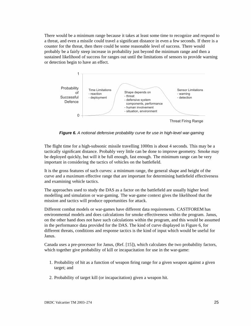
There would be a minimum range because it takes at least some time to recognize and respond toa threat, and even a missile could travel a significant distance in even a few seconds. If there is acounter for the threat, then there could be some reasonable level of success. There wouldprobably be a fairly steep increase in probability just beyond the minimum range and then asustained likelihood of success for ranges out until the limitations of sensors to provide warningor detection begin to have an effect.
1
0
Threat Firing Range
Time Limitations
- reaction
- deployment
Sensor Limitations
- warning
- detection
Shape depends on
- threat
- defensive system
components, performance
- human involvement
- situation, environment
Probability
of
Successful
Defence
Figure 6. A notional defensive probability curve for use in high-level war-gaming
The flight time for a high-subsonic missile travelling 1000m is about 4 seconds. This may be atactically significant distance. Probably very little can be done to improve geometry. Smoke maybe deployed quickly, but will it be full enough, fast enough. The minimum range can be veryimportant in considering the tactics of vehicles on the battlefield.
It is the gross features of such curves: a minimum range, the general shape and height of thecurve and a maximum effective range that are important for determining battlefield effectivenessand examining vehicle tactics.
The approaches used to study the DAS as a factor on the battlefield are usually higher levelmodelling and simulation or war-gaming. The war-game context gives the likelihood that themission and tactics will produce opportunities for attack.
Different combat models or war-games have different data requirements. CASTFOREM hasenvironmental models and does calculations for smoke effectiveness within the program. Janus,on the other hand does not have such calculations within the program, and this would be assumedin the performance data provided for the DAS. The kind of curve displayed in Figure 6, fordifferent threats, conditions and response tactics is the kind of input which would be useful forJanus.
Canada uses a pre-processor for Janus, (Ref. [15]), which calculates the two probability factors,which together give probability of kill or incapacitation for use in the war-game:
1. Probability of hit as a function of weapon firing range for a given weapon against a giventarget; and
2. Probability of target kill (or incapacitation) given a weapon hit.
DRDC Valcartier TM 2003–274 25

The pre-processor does not include any defensive counter in its calculations. The second partessentially calculates the ability of armour to prevent damage. This part could be adapted toincorporate reactive armour or any other very close in defensive factor that might come into playgiven that the weapon will hit the target. The first part, however, could not easily be adaptedsince it is viewed from the weapon perspective and not the defensive perspective. The abovecurves for successful defence, determined by means other than this pre-processor, would give theprobability that the weapon will not hit the target, and so they would be one minus the probabilityof a hit at range of firing. All the other DAS factors, the alert, the timing, the countermeasure, themanoeuvre, all contribute to providing this probability of hit.
6.3.2 Questions for battlefield effectiveness study
The kinds of questions that can be addressed through these higher level models are:
1. Relationship between tactics, countermeasure deployment and overall system effectiveness,
2. Value of the DAS enabling continuation of a mission,
3. Type and number of countermeasures for mission load-out,
4. Impact on group effectiveness,
5. Trade-off between tactics and time to respond (enemy coming within response range), and
6. Battlefield approach in an environment with difficult threats for any DAS.
26 DRDC Valcartier TM 2003–274
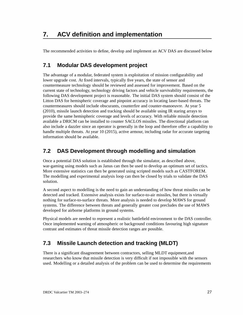
7. ACV definition and implementation
The recommended activities to define, develop and implement an ACV DAS are discussed below
7.1 Modular DAS development project
The advantage of a modular, federated system is exploitation of mission configurability andlower upgrade cost. At fixed intervals, typically five years, the state of sensor andcountermeasure technology should be reviewed and assessed for improvement. Based on thecurrent state of technology, technology driving factors and vehicle survivability requirements, thefollowing DAS development project is reasonable. The initial DAS system should consist of theLitton DAS for hemispheric coverage and pinpoint accuracy in locating laser-based threats. Thecountermeasures should include obscurants, counterfire and counter-manoeuvre. At year 5(2010), missile launch detection and tracking should be available using IR staring arrays toprovide the same hemispheric coverage and levels of accuracy. With reliable missile detectionavailable a DRICM can be installed to counter SACLOS missiles. The directional platform canalso include a dazzler since an operator is generally in the loop and therefore offer a capability tohandle multiple threats. At year 10 (2015), active armour, including radar for accurate targetinginformation should be available.
7.2 DAS Development through modelling and simulation
Once a potential DAS solution is established through the simulator, as described above,war-gaming using models such as Janus can then be used to develop an optimum set of tactics.More extensive statistics can then be generated using scripted models such as CASTFOREM.The modelling and experimental analysis loop can then be closed by trials to validate the DASsolution.
A second aspect to modelling is the need to gain an understanding of how threat missiles can bedetected and tracked. Extensive analysis exists for surface-to-air missiles, but there is virtuallynothing for surface-to-surface threats. More analysis is needed to develop MAWS for groundsystems. The difference between threats and generally greater cost precludes the use of MAWSdeveloped for airborne platforms in ground systems.
Physical models are needed to represent a realistic battlefield environment to the DAS controller.Once implemented warning of atmospheric or background conditions favouring high signaturecontrast and estimates of threat missile detection ranges are possible.
7.3 Missile Launch detection and tracking (MLDT)
There is a significant disagreement between contractors, selling MLDT equipment,andresearchers who know that missile detection is very difficult if not impossible with the sensorsused. Modelling or a detailed analysis of the problem can be used to determine the requirements
DRDC Valcartier TM 2003–274 27

for MLDT and estimate when the technology will be in place to consider implementation on avehicle. Meanwhile the necessary algorithms can be developed for detection and tracking.Eventually vignettes or image sequences can be developed and used as benchmarks to test thecapabilities of contractor prototypes to detect and track various missiles and under variableconditions.
7.4 MLDT Development with third parties
The consensus is that a basic DAS should consist of laser threat detection and obscurants withcounter-manoeuvre as a countermeasure. The next step in technology is the development ofsensors and algorithms to detect missiles, rocket and projectiles directed towards the vehicle.Since this is a major undertaking the technical risk can be reduced to acceptable levels bycollaboration with allies and contractors in developing a common system. Participating in thisendeavour will also give us an opportunity to understand how (and how well) the system worksand how to use it effectively.
7.5 Platform signature management
Vehicle signature management provides the necessary stealth and complements the DAS inproviding a total vehicle protection. The US Army TACOM TARDEC has offered to providemaps or profiles of the radar, visible, infrared and acoustic signatures. These measurementswould be very useful in identifying and eliminating any flaws during the design phase of theprogramme.
7.6 Threat Missile signature trials
Although the SACLOS missile countermeasures perform well during tests, trials carried out bythe US Army and Germany indicate that missile launch detection and tracking cannot be donereliably. As implied above initial flash of the launch motors and igniter can be suppressed androcket propellant designed for low emission. Therefore current UV MAWS technology isinadequate. The detection and tracking of missiles requires more research including spectralimaging and modelling to further sensor development. Both the US Army and Georgia Tech areinterested in collaborating in this area. Researchers at Fort Monmouth are interested indeveloping a signature database for surface-to-surface missiles.
7.7 Soft-kill and hard-kill systems
The need for active armour arose when the MBT became too heavy for additional passive armourand explosive reactive armour could no longer stop modern weapons, (Ref. [12]). The objectiveof active armour is to destroy the projectile when being hit is inevitable. It is therefore the laststep in protection offered by the DAS. Many countries, including Canada, are developing activearmour or hard-kill systems but only the Russians have succeeded in developing systems forproduction. Russian active armour and countermeasure systems include: Drozd, Shtora-1, and
28 DRDC Valcartier TM 2003–274
Arena.
Drozd uses MMW radar sensors on each side of the turret to detect incoming projectiles. Filtersare used to ensure that the system responds only to targets flying at typical ATGM speeds. Onceengaged, one or two small rockets with fragmentation warheads are fired at the target. Poorelevation resolution and a high probability of collateral damage limit Drozd capability. Thesystem has a cost of 30K US and is reported to be about 80% successful against rocket propelledgrenades.
Shtora-1 is actually a soft-kill system using an electro-optical jammer to defeat IR seekingmissiles, SACLOS missiles, laser rangefinders and laser designators. The system comprises fourcomponents:
a laser warning receiver with a 360◦ azimuth and -5 to +25◦ elevation field; and
a bank of forward-firing aerosol-screen grenade launchers mounted on either side of the turret;
the electro-optical interface unit including the jammer, modulator, and control panel;
a control system including the microprocessor.
The screening aerosol can be deployed in less than 3 s at a range of 50-70 m and persists forabout 20 s. In a typical scenario the LWR detects the threat, the turret is oriented in the directionof the threat and the grenades are launched. The screen is a hot smoke covering the spectralregion from 0.4 to 14.0 µm. The heat generated is sufficient to decoy an IR seeking missile. Thejammers emit over the region 0.7 to 2.5 µm injecting a coded pulsed IR signal into the SACLOSguidance system. The jammers provide an effective coverage of ±20◦ in azimuth and 4◦ inelevation within 2 s of target identification.
Arena is the latest and most advanced of the Russian systems and is based on a multidirectionalradar fixed to the turret to detect a potential threat within 50 m of the tank. At a distance between7.8 to 10.06 m from the vehicle, a tethered explosive device, similar to a Claymore mine, islaunched and detonated 1.3 to 3.9 m from the threat. The directed charge of particles destroys themissile. The Arena is an expensive system costing about 300K US.
The Canadian system SAProS, (Ref. [16, 17]) relies on electro-optical sensors to provide an earlywarning. When the projectile is detected the threat is handed over to a radar system for moreprecise target location and timing information. At a suitable distance from the vehicle, a shapedcharge explosive is selected and detonated. The rod of liquid metal, typically travelling atMach 35, has sufficient time to destroy the projectile.
7.8 General purpose DAS for LAV variants
Based on analysis of the ACV threat environment and typical compatibility requirements for theCF and ABCA allies, the following general purpose DAS is proposed as a initial step to theiterative process of configuring an optimum DAS, (Ref. [18]). The general DAS comprises foursubsystems:
DRDC Valcartier TM 2003–274 29

Hard-kill systems are designed to either destroy or deflect the threat away from the vehicle.Active sensors are required to classify the threat and provide ranging data. A system of thistype includes the AWiSS-K, designed by DIEHL Munitionssysteme with:
1. Active staring/scanning sensors
(a) Ka-band search radar providing hemispheric coverage out to 800 m and
(b) Ka-band tracking radar mounted on high-speed grenade launchers.
2. grenades including
(a) blast grenades to deflect kinetic energy projectiles at 50 m and(b) fragmentation grenades to destroy chemical energy threats 15 m from the vehicle.
The search radars are based on radar elements fixed to each corner of the turret. The normalconfiguration consists of two high-speed launchers mounted at the rear of the turret. Eachturret contains 2 grenades and a tracking radar. The launcher slew rate is 90◦ over 120 ms.The total system response time is 400 ms. DIEHL Munitionssysteme estimates that thissystem can be fielded by 2008.
Soft-kill systems rely on obscurants and countermanoeuvres to avoid threats. Sensors for thesesystems detect threats at much longer ranges and are passive to avoid detection. Vehicleswhich can not be manoeuvred easily, such as long-range reconnaissance, must rely onjammers instead. Based technology trends, a 2010 system based largely on off-the-shelfcomponents could be designed as follows:
1. Passive staring/scanning sensors, include scanning optics assumed to be mounted in amini-turret similar to the high-speed launcher above.
(a) mid-infrared staring arrays providing hemispherical coverage, 4096 × 4096pixels per corner operating at 60 Hz
(b) mid-IR scanning array, 1024×1024 pixels with a field of view of 2.5◦× 2.5◦ at60 Hz
(c) a laser illuminator and range-gated camera based on a near-IR scanning array,1024 × 1024 pixels with a field of view of 0.5 ◦× 0.5◦ at 60 Hz
2. Obscuration and countermanoeuvres consisting of:
(a) passive smoke grenades based on metal-flake and chaff providing hemisphericalcoverage, laser dazzling can also be used safely against personnel to fill in the1.5 s gap until full obscuration is achieved,
(b) manoeuvring the vehicle will benefit from various technologies, includingrobotics and MEMS gyroscopes to keep track of the threat.
Information on the vehicle status and driver intent is useful in selecting and automaticallymaintaining an optimum level of obscuration. The following information can be read fromthe vehicle bus:
Vehicle bus variables including vehicle speed to lead the grenade pattern, braking,transmission forward or reverse position, wheel direction, and accelerator position.
Based on these variables and the threat detected, the following
30 DRDC Valcartier TM 2003–274
Grenade variables can be selected including grenade type, the appropriate pattern andthe launch point of each pattern.
Acoustic threat detection will detect muzzle blast and sound waves from a wide range ofprojectiles, and contribute to the performance of the vehicle. Only rarely will the acousticmicrophones outperform the hard-kill and soft-kill sensors but the sensors will contribute tothe overall robustness of the DAS by avoiding catastrophic failure from loss of the morefragile sensors. Acoustic threat detection is useful in detecting small arms fire where flashand blast has been suppressed and under battlefield conditions where smoke and dustinterfere with other sensors.
Detection of active targeting systems consisting of both LWR and RWR are required for bothDAS and IFF functions. The HARLID-based LWR, with the improved ±1◦ resolution, willreduce the burden required to detect the platform over the current 22.5◦ resolution. TheLWR capability should be extended to include detection of beam-rider missile lasers using,for example, WARNLOC. The RWR will detect the more advanced MMW targetingsystems that are now replacing laser-based targeting.
DRDC Valcartier TM 2003–274 31
8. Concluding remarks
The ACV will successfully replace the Cougar tank trainer but will have a low survivabilitytypical of a LAV. Survivability can be increased by:
1. Reducing detection and tracking through signature management and
2. Reducing hit probability with a DAS to detect and counter threats.
Signature management requires a coordinated approach to reduce to background levels: thevehicle radar cross-section and signatures in the following regimes: visible, infrared, electronic,acoustic and magnetic. Expertise in all these areas would require considerable time and resourcesto develop but the US Army TACOM TARDEC is willing to collaborate with us on this mutualproblem.
The DAS should be a federated, modular, mission-configurable system based on more maturetechnology first. The initial DAS with 5-year upgrades would evolve as follows:
1. Initial DAS including HARLID and WARNLOC technology with hemispheric coverageand a typical accuracy of ±1◦. Countermeasures would include obscurants,countermanoeuvres and direct fire.
2. Year 5 (2010), reliable missile launch detection and tracking should be available usinginfrared staring arrays to provide the same hemispheric coverage and levels of accuracy. Adirectional platform can also include a dazzler since an operator is generally in the loop andtherefore offer a capability to handle multiple threats.
3. Year 10 (2015), active armour, based on radar for accurate targeting information to countervirtually all projectile threats and networking to use available resources more effectively.
Based on analysis of the ACV threat environment and typical compatibility requirements for theCF and ABCA allies, the following general purpose DAS is proposed as a initial step to theiterative process of configuring an optimum DAS, (Ref. [18]). The general DAS comprises foursubsystems:
1. Hard-kill systems based on radar as active sensors to classifiy and range the threat,
2. Soft-kill systems on the long-range passive infrared sensors available on the vehicle formanoeuvring and targeting,
3. Acoustic threat detection, complementing the radar and infrared sensors to detect smallarms fire and provide a degree of system reliability
4. Detection of active targeting systems based on LWR and RWR to provide both DAS andIFF capability.
32 DRDC Valcartier TM 2003–274

9. References
1. “The Future Army: Armoured Combat Vehicle Concept Paper,” Fort Frontenac, Kingston, 19May 1998.
2. “Project L2636 Armour Combat Vehicle Statement of Operational Requirement,” Draft no. 3,July 1997.
3. M. Ormrod, P. Bender, and Maj. N. de Tilly, “Quarre de Fer: Analysis of the ACV inWar-Fighting Tasks” ORD PR9817, DOR(J& L) , December 1998.
4. R.G. Lee, T.K. Garland-Collins, D.E. Johnson, E. Archer, C. Sparkes, G.M. Moss and A.W.Mowat, “Guided Weapons,” Bassey’s (UK) Ltd., Third Edition 1998.
5. J. Knowles, “Covering the Spectrum the Army’s EW Triad,” Journal of Electronic DefenseOctober 98, pp 51-81.
6. A. Cantin et al, “Miniaturized Digital High Angular Resolution Laser Irradiation Detector(HARLIDTM) Technology and its Performance as Integrated in a Laser Warning Receiver(LWR) Demonstrator (U),” October 1998, DREV.
7. G. Roy, P. Briere, D. Sanschagrin and G. Couture, “Development of a 76-mm Visual and lRSmoke Screening (VIRSS) Grenade for the Wegmann Launcher,” DREV TR-9605,December 1996, UNCLASSIFIED.
8. J.L. Rapanotti and M. Palmarini, “Dazzle and obscuration strategies for light armouredvehicles”, Ground Target Modeling & Validation Thirteenth Annual Conference, August2002.
9. Personal communication with Maurice A. Clermark, Clermark Inc.
10. D. Richardson, “Steel Alone is no Longer Enough on Tanks,” Armada International 3, 1998pp 34-46.
11. B. Sweetman, “A New Approach to Missile Warning,” Journal of Electronic DefenseOctober, pp 41-78.
12. Capt. T. J. Meyer, “Active Protective Systems: Impregnable Armor or Simply EnhancedSurvivability? ,” Armor, May-June 1998, pp 7-11.
13. “Defensive Aids Suite - Definition Study (DAS-DS), DAS Final Report,” 971483CDRL:005, Computing Devices Canada Ltd., July 1998.
14. B. Manatt, A. Cantin, C. Brown and K. Burrett, “Final Report for the Electro-OpticalPerformance and Countermeasure Trials of SPRINGBOK (U),” TTCP Subgroup Q, QAG-16report OTD-TR-8-95, 21 April 1997, SECRET (Releasable to UK/ CAN/ AUS/ NEWZEA).
15. Maj. L. Mader, and P.S. Ladouceur, “Current Modelling - Weapons and Targets Used byDOR(J& L) Ph/Pk Pre-processor,” DOR(J& L) Research Note RN 9806, March 1998.
DRDC Valcartier TM 2003–274 33

16. “Active Armour Concept Demonstration Program,” Bendix Avelex Inc., May 1990,(Confidential), Volumes 1 and 2 and 4 dated May 1990, Volume 3 dated February 1990
17. “Enhanced Armour Protection System, Phase 2,” Final Report No. AETR 46824,Allied-Signal Aerospace Canada Inc., August 1992, 3 volumes (Confidential).
18. J.L. Rapanotti and M. Palmarini, “Common DAS development for LAV variants,” 14thAnnual Ground Target Modeling and Validation Conference, August 2003.
34 DRDC Valcartier TM 2003–274
List ofsymbols/abbreviations/acronyms/initialisms
ACV – Armoured Combat Vehicle
AOA – Angle-Of-Arrival
APC – Armoured Personnel Carrier
ATIRCM – Advanced Threat InfraRed Countermeasures System
BFV – Bradley Fighting Vehicle
CDA – Commander’s Decision Aid
CECOM – Communications Electronics COMmand
CITV – Commander’s Independent Thermal Viewer
DAS – Defensive Aids Suite
DIRCM – Directional InfraRed CounterMeasure
DLR – Director of Land Requirements
DMCD – Directed Missile Countermeasures Device
FCS – Fire Control System, or Future Combat System
FLIR – Forward Looking InfraRed
HARLIDTM – High Angular Resolution Laser Irradiation Detector
HTI – Horizontal Technology Insertion
IBAS – Improved Bradley Acquisition System
IDS – Integrated Defense System
IFF – Identfication, Friend or Foe
IFV – Infantry Fighting Vehicle
IR – InfraRed
KE – Kinetic Energy
LAV – Light Armoured Vehicle
LRAS3 – Long Range Advanced Scout Surveillance System
LWR – Laser Warning Receiver
MAWS – Missile Approach Warning System
DRDC Valcartier TM 2003–274 35

MBT – Main Battle Tank
MCD – Missile Countermeasure Device
MLDT – Missile Launch Detection and Tracking
MMI – Man-Machine Interface
MMW – MilliMetre Wave
OOTW – Operations Other Than War
OR – Operational Research
SAProS – Smart Armour PROtection System
PM-GSI – Program Manager for Ground System Integration
POMALS – Pedestal Operated Multi-Ammunition Launching System
RWR – Radar Warning System
SACLOS – Semi-Automatic Command to Line of Sight
SSES – Suite of Survivability Enhancement System
VIRSS – Visible InfraRed Smoke Screen
VIS – Vehicle Interface System
WARNLOC – DRDC-V beam-rider detector
36 DRDC Valcartier TM 2003–274

Annex A: Detection and tracking avoidance throughsignature management
Survivability of a light armoured vehicle can be improved by reducing any contrast between thevehicle and the sensor background. The signature or cross-section regimes to be considered arevisible, thermal, electronic, acoustic, radar, magnetic and seismic. Unique signatures thatimprove detection, recognition and identification of the vehicle have to be avoided. An importantsignature reduction technique is to keep the overall size and profile of the ACV as low aspossible. The reduction in size is also important in transportability of the ACV by air.
Visible and infrared signature
The visible regime is one of the more important and can be controlled through traditionalcamouflage, paint and coatings or more advanced active camouflage where the infrared contrastis kept low by cooling or heating surface plates. These phenomena are well understood and canbe analyzed through modelling with the more expensive field trials restricted to validation.
Radar cross-section
The radar cross-section cannot be eliminated but it can be reduced to the background levels.Similar to IR analysis, radar cross-sections can be determined analytically. Surface properties areusually not important but certain geometric features such as large flat surfaces and acute-anglesurfaces that can act as corner reflectors can greatly increase radar returns. Reduction of the radarcross-section is becoming more important. Terminally guided submunitions that normally use IRcontrast to detect the target can be designed to use MMW radar to detect moving targets.Variations of missiles such as Hellfire, which use laser designation, are being adapted to usemmW designators.
Electronic signature
All electro-magnetic emission from the ACV should be suppressed to avoid the possibility ofintercept and detection by enemy electronic support measures. The availability of optical fibrefor data transfer is becoming more important as a means of reducing electronic noise.
Acoustic signature
The acoustic frequencies for the ACV range from 50 Hz-20 kHz. Noise reduction techniquesvary from using quieter components to judicious operation of the vehicle. Surface maps ofvehicle vibration can be used to identify and eliminate constructive wave phases leading toexcessive noise.
Magnetic signature
Reduction of magnetic signature is possible through increased use of non-ferrous materials andwill reduce the susceptibility of the ACV to magnetic fuses and sensors typically found in landmines.
DRDC Valcartier TM 2003–274 37

Seismic signature
Future sensor networks are being developed to distinguish between track and wheel-basedvehicles. Wheeled-based LAVs generate the least amount of vibration.
38 DRDC Valcartier TM 2003–274

Distribution list
Internal
1 – Director General1 – Head Electro-Optical Warfare1 – Head Precision Weapons1 – Head Energetic Materials3 – Document Library1 – Dr. J.L. Rapanotti (author)1 – Mr. G. Pelletier1 – Mr. E. Thibeault1 – Dr. J. Fortin
External
1 – DRDKIM (pdf copy)
1 – Mr. Davis SaintDSTL 5National Defence Headquarters, 12 NT101 Colonel By DriveOttawa, ON, K1A 0K2
1 – Head FFSEDRDC Ottawa3701 Carling AvenueOttawa ON, K1A 0Z4
1 – DLR 2-5National Defence Headquarters, 12 NT101 Colonel By DriveOttawa, ON, K1A 0K2
1 – LCol Luc PetitDLR 3LSTL 1st Floor SE 02555 blvd de la CarriereGatineau QC, K1A 0K2
1 – Capt. Mark McNeilDLR 3-3 LSTL
DRDC Valcartier TM 2003–274 39

1st Floor SE 02555 blvd de la CarriereGatineau QC, K1A 0K2
1 – Director DLSCFort FrontenacPO Box 17000, Stn ForcesKingston, ON, K7B 7B4
1 – Dr. Paul A. RomanArmy Synthetic Environment Coordination OfficeArmy Simulation CentrePO Box 17000, Stn ForcesKingston, ON, K7B 7B4
1 – J2 DSI 7-3National Defence Headquarters101 Colonel By DriveOttawa, ON, K1A 0K2
1 – J2 DSI 7-3-2 ATGMNational Defence Headquarters101 Colonel By DriveOttawa, ON, K1A 0K2
1 – Maj. Gordon FisherJ2 DSI 7-4National Defence Headquarters101 Colonel By DriveOttawa, ON, K1A 0K2
40 DRDC Valcartier TM 2003–274

1 – Maj. Luc NadonJ2 DSI 7-4-4National Defence Headquarters101 Colonel By DriveOttawa, ON, K1A 0K2
1 – Maj. Michel LavalleRWGTNational Defence Headquarters, 6 CBS101 Colonel By DriveOttawa, ON, K1A 0K2
1 – Maj. Les MaderLand Staff SecretariatDecision Support CellNational Defence Headquarters, 12 NT101 Colonel By DriveOttawa, ON, K1A 0K2
DRDC Valcartier TM 2003–274 41

This page intentionally left blank
42 DRDC Valcartier TM 2003–274
dcd03e rev.(10-1999)
UNCLASSIFIED SECURITY CLASSIFICATION OF FORM
(Highest Classification of Title, Abstract, Keywords)
DOCUMENT CONTROL DATA
1. ORIGINATOR (name and address) J.L. Rapanotti, DRDC Valcartier
2. SECURITY CLASSIFICATION (Including special warning terms if applicable) Unclassified
3. TITLE (Its classification should be indicated by the appropriate abbreviation (S, C, R or U) Preliminary study of defensive aids suite technology for the armour combat vehicle programme (U)
4. AUTHORS (Last name, first name, middle initial. If military, show rank, e.g. Doe, Maj. John E.) Rapanotti John L., Cantin André and Dickinson Robert G.
5. DATE OF PUBLICATION (month and year) February 2007
6a. NO. OF PAGES 55
6b .NO. OF REFERENCES 18
7. DESCRIPTIVE NOTES (the category of the document, e.g. technical report, technical note or memorandum. Give the inclusive dates when a specific reporting period is covered.)
Technical Memorandum
8. SPONSORING ACTIVITY (name and address) DRDC Valcartier
9a. PROJECT OR GRANT NO. (Please specify whether project or grant) 2fi
9b. CONTRACT NO.
10a. ORIGINATOR’S DOCUMENT NUMBER TM 2003-274
10b. OTHER DOCUMENT NOS
N/A
11. DOCUMENT AVAILABILITY (any limitations on further dissemination of the document, other than those imposed by security classification)
Unlimited distribution Restricted to contractors in approved countries (specify) Restricted to Canadian contractors (with need-to-know) Restricted to Government (with need-to-know) Restricted to Defense departments Others
12. DOCUMENT ANNOUNCEMENT (any limitation to the bibliographic announcement of this document. This will normally correspond to the Document Availability (11). However, where further distribution (beyond the audience specified in 11) is possible, a wider announcement audience may be selected.)
UNCLASSIFIED
SECURITY CLASSIFICATION OF FORM (Highest Classification of Title, Abstract, Keywords)

dcd03e rev.(10-1999)
UNCLASSIFIED SECURITY CLASSIFICATION OF FORM
(Highest Classification of Title, Abstract, Keywords)
13. ABSTRACT (a brief and factual summary of the document. It may also appear elsewhere in the body of the document itself. It is highly desirable that the abstract of classified documents be unclassified. Each paragraph of the abstract shall begin with an indication of the security classification of the information in the paragraph (unless the document itself is unclassified) represented as (S), (C), (R), or (U). It is not necessary to include here abstracts in both official languages unless the text is bilingual).
On future missions, the Leopard I Main Battle Tank (MBT) and Cougar tank trainer will be replaced by an Armoured Combat Vehicle (ACV) providing direct fire support for Light Armoured Vehicles (LAVs). These new ACVs will be significantly better than the Cougar but lack the survivability of the MBT. To overcome this deficiency a suite of sensors and countermeasures will be proposed. This Defensive Aids Suite (DAS) will include sensor data processing to provide prioritized solutions to threats while interfacing with other vehicle resources through a data bus. The initial DAS design will detect virtually all laser-based threats and counter with obscurants, evasive manoeuvres and direct fire. A modular, federated approach to the design of the DAS, will facilitate upgrades and mission configurability. Future upgrades recommended are missile launch detection and tracking, directed infrared jamming and laser dazzling and a hard-kill system based on radar. Related areas of investigation have been identified including camouflage and signature management to improve vehicle stealth. Additional areas of development include modelling and simulation to determine the benefit of new technologies, sensor, countermeasure and algorithm development, reality models for the DAS processor and crew training. This will be a preliminary study and will serve as a reference for future study in this area.
14. KEYWORDS, DESCRIPTORS or IDENTIFIERS (technically meaningful terms or short phrases that characterize a document and could be helpful in cataloguing the document. They should be selected so that no security classification is required. Identifiers, such as equipment model designation, trade name, military project code name, geographic location may also be included. If possible keywords should be selected from a published thesaurus, e.g. Thesaurus of Engineering and Scientific Terms (TEST) and that thesaurus-identified. If it is not possible to select indexing terms which are Unclassified, the classification of each should be indicated as with the title.)
DAS LAV ACV land vehicle survivability LWR RWR
UNCLASSIFIED
SECURITY CLASSIFICATION OF FORM (Highest Classification of Title, Abstract, Keywords)

Canada’s Leader in Defenceand National Security
Science and Technology
Chef de file au Canada en matièrede science et de technologie pourla défense et la sécurité nationale
WWW.drdc-rddc.gc.ca
Defence R&D Canada R & D pour la défense Canada