preliminary owner’s manual lsr25p studio monitor system ... · 12. wall or ceiling mounting –...
TRANSCRIPT
1
Linear Spatial Reference
LSR25P Studio Monitor System
Preliminary Owner’s Manual
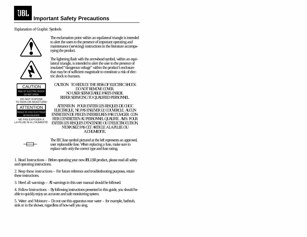
Explanation of Graphic Symbols
The exclamation point within an equilateral triangle is intendedto alert the users to the presence of important operating andmaintenance (servicing) instructions in the literature accompa-nying the product.
The lightning flash with the arrowhead symbol, within an equi-lateral triangle, is intended to alert the user to the presence ofinsulated “dangerous voltage” within the product’s enclosurethat may be of sufficient magnitude to constitute a risk of elec-tric shock to humans.
CAUTION: TO REDUCE THE RISK OF ELECTRIC SHOCKDO NOT REMOVE COVER.
NO USER SERVICEABLE PARTS INSIDE. REFER SERVICING TO QUALIFIED PERSONNEL.
ATTENTION: POUR EVITER LES RISQUES DE CHOCELECTRIQUE, NE PAS ENLEVER LE COUVERCLE. AUCUN
ENTRETIEN DE PIECES INTERIEURES PAR L’USAGER. CON-FIER L’ENTRETIEN AU PERSONNEL QUALIFIE. AVIS: POUREVITER LES RISQUES D’INCENDIE OU D’ELECTROCUTION,
N’EXPOSEZ PAS CET ARTICLE A LA PLUIE OU A L’HUMIDITE.
The IEC fuse symbol pictured at the left represents an approved,user replaceable fuse. When replacing a fuse, make sure toreplace with only the correct type and fuse rating.
1. Read Instructions – Before operating your new JBL LSR product, please read all safetyand operating instructions.
2. Keep these instructions – For future reference and troubleshooting purposes, retainthese instructions.
3. Heed all warnings – All warnings in this user manual should be followed.
4. Follow Instructions – By following instructions presented in this guide, you should beable to quickly enjoy an accurate and safe monitoring system.
5. Water and Moisture – Do not use this apparatus near water – for example, bathtub,sink or in the shower, regardless of how well you sing.
Important Safety Precautions
2
CAUTION
ATTENTION
DO NOT EXPOSETO RAIN OR MOISTURE!
NE PAS EXPOSER ÁLA PLUIE NI Á L'HUMIDITÉ!

6. Cleaning – Clean with a lint free cloth-Do not use any solvent based cleaners. A slightlydamp cloth can also be used on the enclosure surfaces and woofer surrounds.
7. Ventilation – Do not block any ventilation opening, including the Linear DynamicsAperture Port on the LSR monitor systems, by installing these products in accordance withmanufacturers instructions. Do not install near any heat sources such as radiators, heatregisters, stoves or other apparatus that produce heat.
8. Grounding and Power Cords – The power cord supplied with your powered LSR prod-uct has a 3-pin type plug. Do not cut off or damage the grounding pin and once again,don’t use in a shower. If the provided plug does not fit into your outlet, consult an electri-cian for replacement of the obsolete outlet. Protect the power cord from being walked on,or pinched, particularly at plugs, convenience receptacles and the point where they exit theapparatus.
All powered LSR products are fitted with a detachable power cord (supplied) which con-nects to the chassis AC connector. The power cord has an IEC female connector on one endand a male mains connector on the other end. This cord is supplied specifically to accom-modate the different safety and electrical code requirements of individual countries. If youare traveling abroad with your system, test the power mains and be aware of any specificvoltage requirements before operating your system.
9. Options – Only use attachments or accessories specified by the manufacturer.
10. Non-use Periods – Unplug this apparatus during lightning storms, earthquakes, fires,floods, locusts, or when unused for long periods of time.
11. Servicing – Refer all servicing to qualified service personnel. Servicing is requiredwhen the apparatus has been damaged in any way, such as power supply cord or plug isdamaged, liquid has been spilled, or objects have fallen into the LSR monitor, the monitorhas been exposed to rain or moisture, does not operate normally, exhibits signs of schizo-phrenia or other psychosis, or has been dropped.
12. Wall or Ceiling Mounting – The appliance should be mounted to a wall or ceilingonly as recommended by the manufacturer.
13. Carts and Stands – The appliance should be used only with a cart or stand that is rec-ommended by the manufacturer. An appliance and cart combination should be movedwith care. Quick stops, excessive force, and uneven surfaces may cause the appliance andcart combination to overturn.
Important Safety Precautions
3
The information contained in this document isconfidential and the copyright of JBL Professional. Toconvey its contents, in part or in whole to any third partywithout prior written authorization is a violation of thecopyright. © JBL Professional 2000.
1.0 Introduction ................................................................................................................1
2.0 Getting Started ............................................................................................................22.1 Unpacking ..................................................................................................22.2 Placement ..................................................................................................22.3 Audio Connections ....................................................................................22.4 AC Power Connections ..............................................................................32.5 Making Sound Happen ..............................................................................3
3.0 General Operation......................................................................................................43.1 Audio Connections ....................................................................................43.2 AC Power Connections ..............................................................................43.3 Audio Level Adjustment..............................................................................53.4 High Frequency Adjustments ....................................................................53.5 80 Hz High Pass Filtering ..........................................................................63.6 Workstation Boundary Compensation ......................................................63.7 LED Indication ..........................................................................................63.8 Mounting ....................................................................................................6
4.0 Specifications ............................................................................................................84.1 System Specifications ................................................................................84.2 Transducer Specifications ..........................................................................94.3 Performance Graphs ................................................................................10
Appendix A: Wiring Recommendations ........................................................................12
4
Table of Contents

5
Congratulations on selecting the LSR Linear Spatial Reference Studio Monitors.They represent the sum total of our research and development efforts in sound reproduc-tion. While we don’t expect you to read the entire manual, we do suggest section 2 to getstarted. At that time, you should have a system to listen to while you intensely study the restof the manual for maximum performance.
Beginning with a blank CAD screen, today’s equivalent to a clean sheet of paper,the LSR products have been based on fundamental research into all aspects of monitordesign. JBL designed the entire system starting with the materials and topologies of theindividual transducers, through to the final assembly of the diecast parts. The results areincredibly accurate reference systems with high dynamic capabilities and astonishingly lowdistortion.
New LSR Technologies
Linear Spatial Reference A measurement and design philosophy that takes into accountmany additional factors beyond on-axis frequency response. The overall performance ofthe systems are optimized within a wide listening window for exceptional performance in avariety of acoustic spaces. Attention to these critical aspects results in a rock solid imagethat remains consistent throughout the entire listening field.
Linear Dynamics Aperture™ Contoured ports virtually eliminate high-end turbulencefound in traditional port designs. This provides more accurate low frequency performanceat higher output levels.
Titanium Composite High Frequency Device Using patented technology, the high frequencydevice incorporates titanium and composite materials to improve transient response andreduce distortion. By reducing distortion in the lower operating range, where the ear ismost sensitive, ear fatigue is radically reduced.
Elliptical Oblate Spheroidal (EOS) Waveguide Designed for a targeted listening window of+/- 30˚ horizontally and +/- 15˚ vertically, the EOS provides a frequency response throughthe entire window of 1.5 dB from on-axis. This allows listeners, even far off-axis to hear anaccurate representation of the on-axis response.
Workstation Boundary CompensationLow and mid frequencies can be adjusted to optimize performance where boundaries suchas video monitors and desktop surfaces are present in the monitoring environment.
Section 1: Introduction
1

2.1 Unpacking:
An easy way to safely unpack your monitors is to open the top of the box, keepthe filler piece on, and roll the box upside down. The box can then be slipped off. This alsoworks in reverse for repacking the units to take them to the next session.
2.2 Placement:
The design of the LSR systems lend themselves to a wide variety of placementoptions. Covered here is a typical stereo setup for near to mid field monitoring. A deeperdiscussion of multi-channel sound setup is available from JBL in Tech Note Volume 3,Number 3.
Listening Distance: By evaluating a broad cross-section of studio environ-ments, it was determined that the common listening position at recording consoles is gen-erally 1 to 1.5 meters (3 to 5 feet) for near field applications. For mid-field applications, 2to 3 meters is more likely. The real key to successful stereo placement is to form an equilat-eral triangle between the monitors and the prime listening position. As shown below, thedistance between the monitors and the distance between each monitor and the center ofthe listener’s head are equivalent.
Vertical vs. Horizontal Placement: The LSR25P near field is designed tobe positioned vertically. This orientation eliminates the phase shifts that occur when therelative distances between the woofer, tweeter and the listening position change.
Angling towards the listening position: LSR monitors should be angledto directly face the listener. The center of the high frequency transducer should be on-axiswith the ear level of the listener.
2.3 Audio Connections:
LSR25P Audio Connections: The LSR25P comes with an XLR and RCA con-nectors to accommodate a wide range of signal levels and balanced or unbalanced config-urations. The XLR input is nominal +4 dBu sensitivity and the RCA input is -10 dBV.Variable user calibration can also be accommodated using the front mounted volume con-trol. Positive voltage applied to Pin 2 of the XLR or the pin of the RCA jack will produce aforward motion in the low frequency cone.
Section 2: Getting Started
2
2.4 AC Power Connections:
The LSR25P has power transformers which allow them to be used with multipleAC supply voltages around the world. Before connecting the unit to AC power, confirm thatthe switch setting on the rear of the unit is set to the proper position and the fuse is the cor-rect rating. The LSR25P will accept voltages from 100-120 or 200-240 Volts, 50-60 Hz whenthe voltage setting and fuse is correct. The ground terminal of the IEC plug is required bywiring codes and regulations. It must always be connected to the electrical installationsafety ground. The LSR units have carefully designed internal grounding and balancedinputs and outputs to reduce the possibility of ground loops (hum). If hum occurs, seeAppendix A for suggested audio signal wiring and system grounding.
2.5 Making Sound Happen:
After connections are made, the next step is to power up all equipment before theamplified LSR25P monitors. Reduce the level of the monitor outputs of your console orpreamp and also turn the volume on the front of the LSR25P monitors fully counter clock-wise for minimum gain. You can now turn on the monitors. There is a small delay withthe turn on to accommodate for clicks and thumps from upstream equipment. When theGreen LED on the front panel turns on, the units are ready to go. Slowly advance the gainof the LSR25P monitors and check for hum or noise. If everything is correct, advance thethe console to feed the monitoring system and sit back and enjoy. If there is excessivehum, noise or no signal see Appendix A on suggested wiring practices.
Section 2: Getting Started
3
3.0 Introduction:
The LSR25P Bi-amplified reference monitor sets a new standard for exceptionalperformance in a compact near field design. Using a combination of advanced transducerengineering and powerful drive electronics, the LSR25P will stand up to the most demand-ing sessions.
The 5.25” woofer is based on JBL’s Symetrical Field Geometry (SFG)® technology.With a massive 1.5” drive coil, excursion capability is maximized while retaining excellentdistortion performance. The heavy magnetic structure keeps power compression to a mini-mum to reduce spectral shift as power levels increase. The tempered paper cone forms arigid piston and is supported by a soft butyl rubber surround. The entire driver is shieldedfor use near video monitors and other equipment sensitive to magnetic fields.
The high frequency device is a 1" composite diaphragm integrated with anElliptical Oblate Spheroidal (EOS) Waveguide with 100 x 60 degree dispersion which iscritical to the smooth spatial response required in today’s working environments. Thedesign, as with the woofer above, is shielded.
3.1 Audio Connections:
The LSR25P comes with an XLR and RCA connectors to accommodate a widerange of signal levels and balanced or unbalanced configurations. The XLR input is nomi-nal +4 dBu sensitivity and the RCA input is -10 dBV. Variable user calibration can also beaccommodated using the front mounted volume control. Positive voltage to Pin 2 of theXLR or the pin of the RCA jack will produce a forward motion in the low frequency cone.
3.2 AC Power Connections:
The LSR25P has power transformers which allow them to be used with multipleAC supply voltages around the world. Before connecting the unit to AC power, confirm thatthe switch setting on the rear of the unit is set to the proper position and the fuse is the cor-rect rating. The LSR25P will accept voltages from 100-120 or 200-240 Volts, 50-60 Hz whenthe voltage setting and fuse is correct. The ground terminal of the IEC plug is required bywiring codes and regulations. It must always be connected to the electrical installationsafety ground. The LSR units have carefully designed internal grounding and balancedinputs and outputs to reduce the possibility of ground loops (hum). If hum occurs, seeAppendix A for suggested audio signal wiring and system grounding.
Section 3: General Operation
4
3.3 Audio Level Adjustment:
The audio level sensitivity of the LSR25P can be adjusted for almost any situa-tion. Monitor outputs on consoles are normally at a nominal level of +4 dBu or -10 dBv.These are typically called professional and semiprofessional, respectively.
As shipped from the factory, the nominal input level of the XLR input is +4 dBuand -10 dBv for the RCA input. A nominal level to these inputs will produce an output of96 dB SPL at 1 meter in an anechoic environment. This allows the user to get a goodmatch when using either professional or semiprofessional equipment. If less sensitivity isneeded the front channel volume control can be adjusted down. The front panel adjust-ment gives 9 dB of attenuation in the 12 o’clock position.
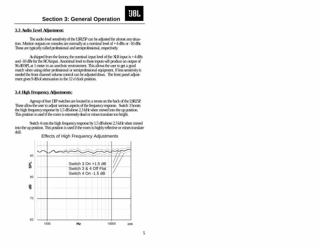
3.4 High Frequency Adjustments:
A group of four DIP switches are located in a recess on the back of the LSR25P.These allow the user to adjust various aspects of the frequency response. Switch 3 booststhe high frequency response by 1.5 dB above 2.3 kHz when moved into the up position.This position is used if the room is extremely dead or mixes translate too bright.
Switch 4 cuts the high frequency response by 1.5 dB above 2.3 kHz when movedinto the up position. This position is used if the room is highly reflective or mixes translatedull.
Effects of High Frequency Adjustments
Section 3: General Operation
5
Switch 3 On +1.5 dBSwitch 3 & 4 Off FlatSwitch 4 On -1.5 dB
3.5 80 Hz High Pass For Use With Subwoofers:
The Low Frequency cut off can be adjusted to either 40 Hz or 80 Hz. Thisallows easy use of powered subwoofers without requiring complicated cabling orloop throughs. Switch 1 selects the 80 Hz setting when in the up position.
3.6 Workstation Boundary Compensation:
The bass and low mid frequency response of the LSR25P can be adjusted to com-pensate when the system is located near a wall or other boundary surface.
3.7 LED Indication:
A single Bi-Color LED indicator is located on the front of the LSR25P. In normaloperation, this LED will be GREEN. At the onset of amplifier clipping in either the low orhigh frequency amplifier, the LED will flash RED. Continual RED flashing of this LEDindicates that levels should be reduced.
3.8 Mounting:
The LSR25P has built in mounting point for use with Omnimount® 75 Seriesbrackets. These are located on the upper back of the cabinet. The threaded holes accept a1/4” diameter machine screw with a pitch of 20 threads per inch.
6
Section 3: General Operation

7
Section 3: General Operation

Section 4: Specifications
8
System: LSR25PFrequency Response (+1, -2 dB): 70 Hz - 20 kHzEnclosure Resonance Frequency: 55 Hz
Low Frequency Extension: User controls set to default-3 dB: 65 Hz-6 dB: 56 Hz
-10 dB: 48 HzLow - High Frequency Crossover: 2.3 kHz
4th-Order Electroacoustic Linkwitz-RileyDistortion, 96 dB SPL, 1m:
Mid-High Frequency (150 Hz - 20 kHz):2nd Harmonic: <0.5%3rd Harmonic: <0.5%
Low Frequency (<150 Hz):2nd Harmonic: <2%3rd Harmonic: <3%
Maximum SPL (90 Hz - 20 kHz): >106 dB SPL / 1 mMaximum Peak SPL (90 Hz - 20 kHz): >109 dB SPL / 1 m
Signal Input: XLR, BalancedRCA, UnbalancedPositive voltage applied to XLR Pin 2 (RCA tip) produces outward woofer motion.
Calibrated Input Sensitivity:XLR, +4 dBu: 96 dB/1 mRCA, -10 dBV: 96 dB/1 m
AC Input Voltage: 115/230 VAC, 50/60 Hz (User Selectable)AC Input Voltage Operating Range: +/- 15%
AC Input Connector: IECLong Term Maximum System Power: 110 Watts (IEC265-5)
Self Generated Noise Level: <10 dBA SPL/1 m User Controls:High Frequency Control (3 kHz - 20 kHz): +1.5 dB, 0 dB, -1.5 dB
Workstation Boundary Compensation: Active or BypassLow Frequency Alignment: 36 dB/Octave Butterworth hi pass at 40 Hz
36 dB/Octave Bessel hi-pass at 80 Hz(For use with Subwoofer)
Variable Input Attenuation: 0 - 26 dB (9 dB at 12 o’clock)Amplifiers:
Low Frequency:Topology: Bridged Class A-B Monolithic
Sine Wave Power Rating: 100 Watts (<0.1% THD into rated impedance)THD+N, 1/2 power: <0.05%
High Frequency:Topology: Class A-B, Monolithic
Sine Wave Power Rating: 50 watts (<0.1% THD into rated impedance)THD+N, 1/2 power: <0.05%
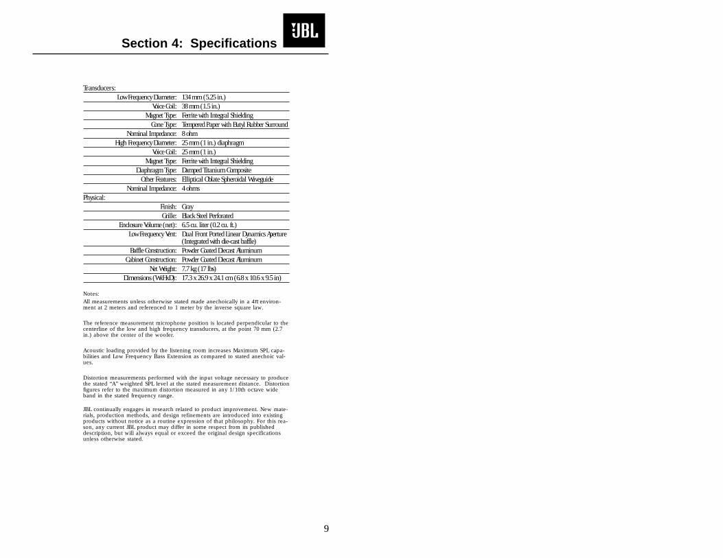
Transducers:Low Frequency Diameter: 134 mm (5.25 in.)
Voice Coil: 38 mm (1.5 in.) Magnet Type: Ferrite with Integral Shielding
Cone Type: Tempered Paper with Butyl Rubber SurroundNominal Impedance: 8 ohm
High Frequency Diameter: 25 mm (1 in.) diaphragmVoice Coil: 25 mm (1 in.)
Magnet Type: Ferrite with Integral ShieldingDiaphragm Type: Damped Titanium Composite
Other Features: Elliptical Oblate Spheroidal WaveguideNominal Impedance: 4 ohms
Physical:Finish: Gray Grille: Black Steel Perforated
Enclosure Volume (net): 6.5 cu. liter (0.2 cu. ft.)Low Frequency Vent: Dual Front Ported Linear Dynamics Aperture
(Integrated with die-cast baffle)Baffle Construction: Powder Coated Diecast Aluminum
Cabinet Construction: Powder Coated Diecast AluminumNet Weight: 7.7 kg (17 lbs)
Dimensions (WxHxD): 17.3 x 26.9 x 24.1 cm (6.8 x 10.6 x 9.5 in)
Notes:All measurements unless otherwise stated made anechoically in a 4π environ-ment at 2 meters and referenced to 1 meter by the inverse square law.
The reference measurement microphone position is located perpendicular to thecenterline of the low and high frequency transducers, at the point 70 mm (2.7in.) above the center of the woofer.
Acoustic loading provided by the listening room increases Maximum SPL capa-bilities and Low Frequency Bass Extension as compared to stated anechoic val-ues.
Distortion measurements performed with the input voltage necessary to producethe stated “A” weighted SPL level at the stated measurement distance. Distortionfigures refer to the maximum distortion measured in any 1/10th octave wideband in the stated frequency range.
JBL continually engages in research related to product improvement. New mate-rials, production methods, and design refinements are introduced into existingproducts without notice as a routine expression of that philosophy. For this rea-son, any current JBL product may differ in some respect from its publisheddescription, but will always equal or exceed the original design specificationsunless otherwise stated.
Section 4: Specifications
9
10
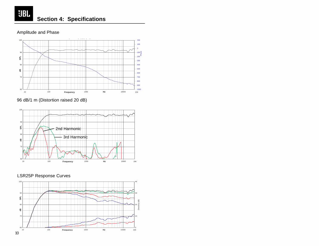
LSR25P Response Curves
Section 4: Specifications
Hz100 1000 1000060
70
80
90
100
Pha
se
-1000
-900
-800
-700
-600
-500
-400
-300
-200
-100
0
100
200
20 20K
dB
SP
L
Frequency
J o ess o a
Amplitude and Phase
Hz100 1000 1000060
70
80
90
100
20 20K
dB
SP
L
Frequency
J o ess o a
96 dB/1 m (Distortion raised 20 dB)
Hz100 1000 1000060
70
80
90
100
Dire
ctiv
ity (d
B)
0
10
20
30
40
20 20K
dBS
PL
Frequency
2nd Harmonic
3rd Harmonic

11
Section 4: Specifications
By now, you have probably plugged the LSR monitors in and are making greatmusic. However, for optimum performance, some attention to wiring details now canreduce system degradation later. These cabling recommendations follow standard wiringpractice for balanced and unbalanced inputs.
Balanced Sources
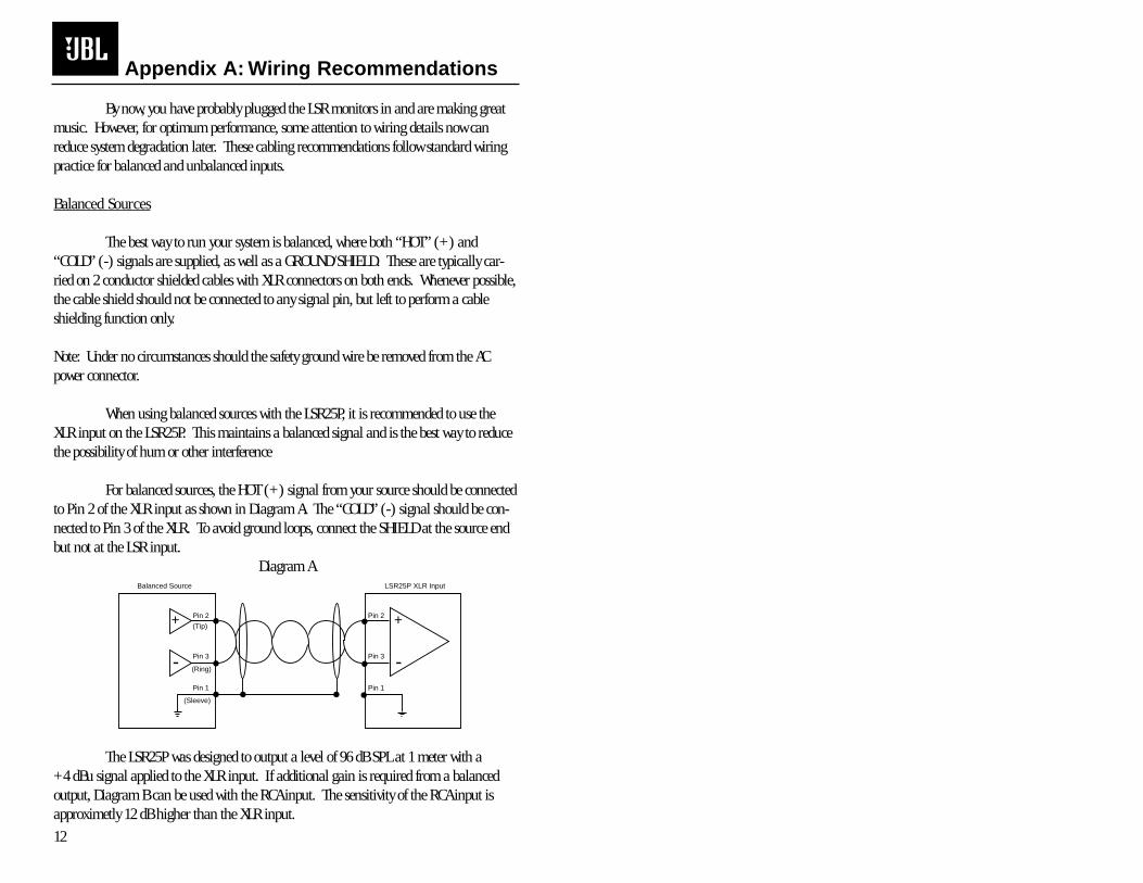
The best way to run your system is balanced, where both “HOT” (+) and“COLD” (-) signals are supplied, as well as a GROUND/SHIELD. These are typically car-ried on 2 conductor shielded cables with XLR connectors on both ends. Whenever possible,the cable shield should not be connected to any signal pin, but left to perform a cableshielding function only.
Note: Under no circumstances should the safety ground wire be removed from the ACpower connector.
When using balanced sources with the LSR25P, it is recommended to use theXLR input on the LSR25P. This maintains a balanced signal and is the best way to reducethe possibility of hum or other interference
For balanced sources, the HOT (+) signal from your source should be connectedto Pin 2 of the XLR input as shown in Diagram A. The “COLD” (-) signal should be con-nected to Pin 3 of the XLR. To avoid ground loops, connect the SHIELD at the source endbut not at the LSR input.
Diagram A
The LSR25P was designed to output a level of 96 dB SPL at 1 meter with a +4 dBu signal applied to the XLR input. If additional gain is required from a balancedoutput, Diagram B can be used with the RCA input. The sensitivity of the RCA input isapproximetly 12 dB higher than the XLR input.
12
Appendix A: Wiring Recommendations
+
-
+
-
Pin 2
Pin 3
Pin 1
Pin 2
(Tip)
(Ring)
(Sleeve)
Pin 3
Pin 1
LSR25P XLR InputBalanced Source
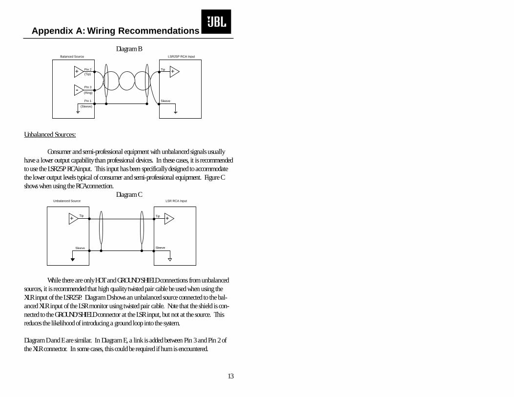
Diagram B
Unbalanced Sources:
Consumer and semi-professional equipment with unbalanced signals usuallyhave a lower output capability than professional devices. In these cases, it is recommendedto use the LSR25P RCA input. This input has been specifically designed to accommodatethe lower output levels typical of consumer and semi-professional equipment. Figure Cshows when using the RCA connection.
Diagram C
While there are only HOT and GROUND/SHIELD connections from unbalancedsources, it is recommended that high quality twisted pair cable be used when using theXLR input of the LSR25P. Diagram D shows an unbalanced source connected to the bal-anced XLR input of the LSR monitor using twisted pair cable. Note that the shield is con-nected to the GROUND/SHIELD connector at the LSR input, but not at the source. Thisreduces the likelihood of introducing a ground loop into the system.
Diagram D and E are similar. In Diagram E, a link is added between Pin 3 and Pin 2 ofthe XLR connector. In some cases, this could be required if hum is encountered.
13
Appendix A: Wiring Recommendations
+
-
Tip
Sleeve
Pin 2
(Tip)
(Ring)
(Sleeve)
Pin 3
Pin 1
LSR25P RCA InputBalanced Source
+
Tip
Sleeve Sleeve
Tip+
LSR RCA InputUnbalanced Source
+
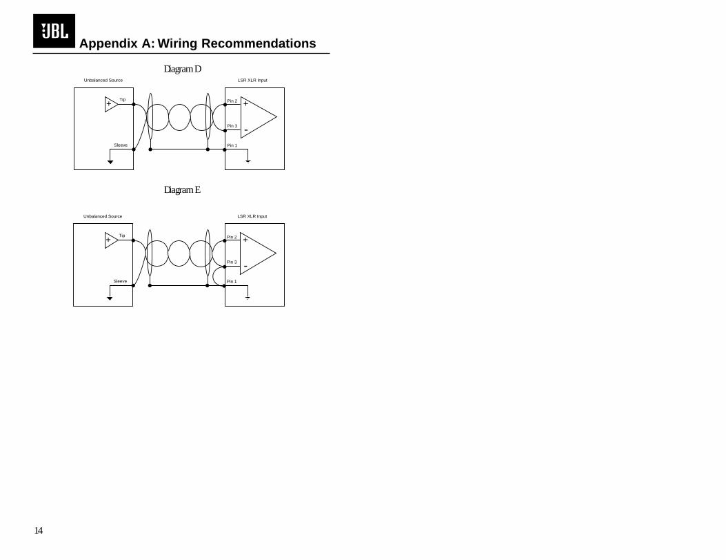
Diagram D
Diagram E
14
Appendix A: Wiring Recommendations
Tip
Sleeve
+ +
-
Pin 2
Pin 3
Pin 1
LSR XLR InputUnbalanced Source
Tip
Sleeve
+ +
-
Pin 2
Pin 3
Pin 1
LSR XLR InputUnbalanced Source


JBL Professional8500 Balboa Boulevard, P.O. Box 2200Northridge, California 91329 U.S.A.www.jblpro.com
A Harman International Company
LSR25P MANUAL98100056-00CRP 1M11/99