preliminary geotechnical exploration 15-acre tract ... preliminary geotec.pdf · for this...
TRANSCRIPT

11440 Reeder Rd. · Dallas, Texas 75229
Tel. 214-352-4100 Fax. 214-352-4811
PRELIMINARY GEOTECHNICAL EXPLORATION
15-Acre Tract Silverleaf Phase II
North Tarrant Parkway Keller, Texas
FARGO Report No. G07-1329
November 2007
Prepared for:
WILBOW CORPORATION Dallas, Texas


Fargo Report No. G07-1329 FARGO CONSULTANTS, INC. FARGO CONSULTANTS, INC.
Geotechnical Engineering · Construction Materials Testing · Environmental Services
www.dallasfargo.com
CONTENTS Page
INTRODUCTION ........................................................................................................................................... 1
Project Information ..................................................................................................................... 1
Purpose of Work ......................................................................................................................... 1
FIELD EXPLORATION ................................................................................................................................ 1
LABORATORY TESTING ............................................................................................................................ 2
GENERAL SITE CONDITIONS ................................................................................................................ 3
Site Description ........................................................................................................................... 3
Subsurface Stratigraphy, General ................................................................................................ 3
Subsurface Stratigraphy .............................................................................................................. 4
Groundwater ............................................................................................................................... 4
ANALYSES AND PRELIMINARY DESIGN INFORMATION ......................................................... 4
Soil Movement ............................................................................................................................ 4
Monolithic “Waffle” Slab-on-Grade Foundation System, General ............................................ 5
Subgrade Modification by Moisture Conditioning ..................................................................... 5
EARTHWORK ................................................................................................................................................. 6
Fill Compaction .......................................................................................................................... 6
ROADWAYS PAVEMENT SUBGRADE TREATMENT ..................................................................... 8
LIMITATIONS ................................................................................................................................................. 9
ILLUSTRATIONS
Site Plan (Plate A) Boring Logs (Plates 1 to 4)
Terms And Symbols Used On Boring Logs (Plate B)
APPENDIX
RECOMMENDED SPECIFICATIONS FOR CONTROLLED EARTHWORK ON HOUSING AND URBAN DEVELOPMENT PROJECTS

Fargo Report No. G07-1329 FARGO CONSULTANTS, INC. Page 1 FARGO CONSULTANTS, INC.
Geotechnical Engineering · Construction Materials Testing · Environmental Services
www.dallasfargo.com
INTRODUCTION
Project Information
The site consists of and approximate 15-Acre tract of land located to the northwest of the intersection of
North Tarrant Parkway and Sarah Brooks Drive in Keller, Texas. The general location of the site is shown
on Plate A in the Illustrations section of this report. It is our understanding that the site is being considered
for residential development called, Silverleaf Phase II. Grading plans were not available at the time of our
study.
Purpose of Work
The primary purpose of this preliminary geotechnical study was to explore subsurface conditions at the
locations of limited and widely spaced borings. Preliminary engineering analyses have been performed based
on the information obtained from the borings advanced and based on the results of laboratory tests
performed on selected representative samples obtained from the borings. The analyses have been used to
develop preliminary geotechnical related information for general estimation purposes.
The preliminary information provided in this report has been developed from data obtained from the
borings, which depict subsurface conditions only at the specific boring locations and at the particular time
designated on the logs. Subsurface conditions at other locations may differ from those observed in the
limited borings advanced for this preliminary study.
Additional borings, sampling, laboratory testing and engineering analyses will be required as part of the final
geotechnical prior to design of any structures at the referenced site. Further studies may reveal different
subsurface conditions beyond the borings advanced as results of naturally occurring subsurface conditions or
future grading of the site. Changes in subsurface conditions may warrant final design recommendations
different from the preliminary information provided in this report.
FIELD EXPLORATION
For this preliminary exploration, we have advanced a total of 4 borings to a maximum depth of 20 feet at the
site to explore subsurface conditions at the boring locations.
Boring locations have been marked in the field by using a basic GPS (Global Positioning System) device,
using a measuring wheel, and by pacing. As a guide in locating the borings, landmarks, which could be
identified in the field and as shown on the provided site plan, were used.

Fargo Report No. G07-1329 FARGO CONSULTANTS, INC. Page 2 FARGO CONSULTANTS, INC.
Geotechnical Engineering · Construction Materials Testing · Environmental Services
www.dallasfargo.com
The boring locations shown on Plate A should be considered approximate with reference to the methods
used to locate them. Accurate marking of boring locations will require surveying services, which was beyond
the scope of this study.
Borings were advanced between sampling intervals by means of a truck-mounted drilling rig using
continuous flight augers. Shelby tube samplers were used to obtain intermittent undisturbed soil samples in
general accordance with the applicable ASTM procedures and local practice experience:
Shelby tube soil samples were hydraulically extruded from the sampler, examined, and visually classified.
One representative portion of each sample was sealed in a plastic bag and transported to our laboratory for
further visual examination and testing.
A record of field observations was maintained in the form of field logs visually describing the subsurface
materials encountered and other pertinent field data. These logs were later edited to incorporate information
obtained from laboratory examination and testing.
The boring logs with description of materials encountered are shown on the Log of Borings (Plates 1
through 4) in the report Illustrations. Descriptions of terms and symbols used on the logs are presented on
Plate B after the log of borings.
LABORATORY TESTING
Samples were examined in the laboratory and visually classified in accordance with Unified Soil Classification
System (USCS). Laboratory tests were assigned on selected samples. A brief description of the
measurements and tests performed follows:
Hand penetrometer resistance.
Moisture content.
Liquid limit and plastic limit (collectively termed as Atterberg limits).
Dry unit weight.
Unconfined compression.
Absorption swell.
Laboratory tests were performed to: evaluate index properties, confirm visual classifications, evaluate the
undrained shear strength of selected samples, and to aid in evaluating general soils’ potential for volume
change. The laboratory tests were performed in general accordance with the applicable ASTM procedures.

Fargo Report No. G07-1329 FARGO CONSULTANTS, INC. Page 3 FARGO CONSULTANTS, INC.
Geotechnical Engineering · Construction Materials Testing · Environmental Services
www.dallasfargo.com
Absorption swell test was performed on selected samples of cohesive soils after applying overburden
pressure with reference to the sample’s approximate depth. Swell test results were used to further evaluate
volume change potential at in-situ moisture levels of the selected samples. The results of routine laboratory
tests and classification of the soils are presented on the individual log of borings in the report Illustrations.
The results of absorption swell test are tabulated below:
Boring No.
Approx. depth (feet)
Liquid Limit
Plastic Limit
Plasticity Index (PI)
Initial Moisture
(%)
Final Moisture
(%)
Swell (%)
B-1 3 64 24 40 18 26 4.8
B-2 14 70 25 45 23 24 0.3
B-3 5 55 21 34 18 24 2.6
B-4 7 59 23 36 22 25 1.8
GENERAL SITE CONDITIONS
Site Description
The site consists of an approximate 15-Acre tract of land located to the northwest of the intersection of
North Tarrant Parkway and Sarah Brooks Drive in Keller, Texas. The general location of the site is shown
on Plate A in the report Illustrations.
At the time of our observations, the site was covered with vegetation and scattered trees. The eastern one-
third and western two-thirds of the site was divided by a fence line. Various areas of the site contained dense
trees. The east, north, and west boundaries of the site were tree lined. The far southern portion of the site
was developed with three residences, storage structure, and a swimming pool. A stock pile of construction
debris and household items was noted to the northwest of the residences. The far northwestern area of the
site contained a stock pond with water. The site is bounded to the south by Wilson Lane, to the east by a
church and associated area parking, to the north by an existing residential development and to the west by an
open tract of land. Based on visual observation, the surface of the site has a gentle downward slope from
northwest to southeast.
Subsurface Stratigraphy, General
General subsurface conditions described below are based on the information obtained from limited number
of borings that were widely spaced across the expanse of the site. Client and excavation contractors should
clearly understand that boring locations shown on Plate A are approximate and subsurface conditions may
vary at other locations throughout the site as compared to those found at the actual locations where borings
were advanced.

Fargo Report No. G07-1329 FARGO CONSULTANTS, INC. Page 4 FARGO CONSULTANTS, INC.
Geotechnical Engineering · Construction Materials Testing · Environmental Services
www.dallasfargo.com
Subsurface Stratigraphy
Geological maps indicate the formation in the general area of the project site to consist of Woodbine
formation. The subsurface conditions encountered at each boring location are depicted on the log of borings
in the Illustrations section. Description of each stratum with its depth and thickness encountered in the
borings is shown on the logs. A brief discussion of the generalized stratigraphy at the study area is presented
below:
Subsurface materials encountered in the borings in general consist of light brown to brown clay, underlain by
tan and gray clay, and deeper underlain by tan and gray shaley clay soils. The tan and gray soils extended to
the 20-foot maximum depths of the borings. They had Liquid Limits of 55 to 72 and Plasticity Indices of 34
to 46 and are classified as CH, according to the Unified Soil Classification System (USCS). The consistency
of these soils was hard as determined by a hand penetrometer device.
Groundwater
Subsurface seepage water was not encountered in any of the borings during drilling and sampling and the
borings remained dry at completion of field exploration. Groundwater levels can be different at the time of
construction. Seasonal variations in the amount of rainfall, runoff or landscape irrigation from nearby
properties, or future construction activities can cause changes in the depth to groundwater.
ANALYSES AND PRELIMINARY DESIGN INFORMATION
Soil Movement
Laboratory test results indicate the clay soils encountered in the borings at this site are active soils and can be
expected to experience substantial volume changes (swell and shrink) with variations in moisture content.
The movements also are influenced by other factors including but not limited to soil properties, overburden
pressures, surface drainage conditions, cut, or fill placement.
Movements of shallow foundations resting on active soils also are significantly influenced by the moisture
profile of the subsurface soils at the time of construction. The in-situ moisture conditions of the clay soils
encountered in borings advanced on October 2007 at the referenced site are in a dry condition. The greatest
potential for post-construction movement occurs if active clays are dry at the time of construction of
foundation.

Fargo Report No. G07-1329 FARGO CONSULTANTS, INC. Page 5 FARGO CONSULTANTS, INC.
Geotechnical Engineering · Construction Materials Testing · Environmental Services
www.dallasfargo.com
Methods used in our preliminary estimation for magnitude of potential for vertical soil movements included
the following:
Texas Department of Transportation, Method 124-E.
Results of absorption swell tests.
With reference to the aforesaid, our estimated magnitude of soil potential for movements below October
2007 grade at the location of the borings is on the order of 5 to 6 inches for dry Subgrade conditions.
Final geotechnical exploration in conjunction with site grading may warrant magnitude of potential vertical
movements different than those mentioned in this report.
Monolithic “Waffle” Slab-on-Grade Foundation System, General
A monolithic “waffle” slab-on-grade foundation system may be considered at the referenced site. However,
considering estimated magnitude of potential soil movement, modification of subgrade by moisture
conditioning will be required to lower soil movement to a tolerable limit. Generally, areas with potential soils
vertical movements on the order of 4.5 inches or greater may not be suitable for construction of slab-on-
grade without modification of subgrade to lower soil movement. Moisture conditioning of subgrade is to
reduce potential vertical movements to a tolerable limit with reference to slab-on-grade type foundation
system.
Subgrade Modification by Moisture Conditioning
Typical economical ways to modify the subgrade to reduce soil potential for movements consist of the
following:
Preswelling of the soils by water pressure injection upon completion of grading
Excavation of soils prior to grading and elevating the moisture of soils during placement and final grading
In general, subgrade modification by excavation is considered economical, as compared to water pressure
injection, in areas where placement of fill with substantial fill thickness is required during grading. Details of
the procedures with reference to subgrade modification by moisture conditioning will be provided upon
completion of grading plans and after advancing additional borings, sampling, testing and engineering
analyses.
The foundation may be conceptually designed as grid-type slab-on-ground foundation system reinforced with
post-tension tendons or conventional rebar and should be designed to provide sufficient rigidity to the
foundation system to withstand soil vertical movements. For estimating purposes, a net allowable soil

Fargo Report No. G07-1329 FARGO CONSULTANTS, INC. Page 6 FARGO CONSULTANTS, INC.
Geotechnical Engineering · Construction Materials Testing · Environmental Services
www.dallasfargo.com
bearing pressure in the range of 1500 to 2000 pounds per square foot may be considered for conceptual
design of all grade beams.
Preliminary information presented in this report should not be used for final design of any structure.
Additional borings, sampling, laboratory testing and engineering analysis will be required to provide final
geotechnical related design parameters.
EARTHWORK
All vegetation and topsoil containing organic materials should be cleared and grubbed at the beginning of
earthwork construction. Imported materials to be used during fill placement should consist of a clean soil,
free of any objectionable material, and no rock fragments greater than 4 inches in maximum dimension.
As noted, the magnitude of soil vertical movement can be reduced by moisture conditioning of soils. These
procedures can be incorporated into site grading operation. Details of procedures with reference to moisture
conditioning during site grading operation will be provided upon completion of grading plans and after
advancing additional borings, sampling, testing and engineering analyses. The following describe general
earthwork operation if moisture conditioning is performed after the completion of earthwork.
After completion of the necessary stripping, clearing, and excavating and prior to placing any required fill, the
exposed subgrade should be tested and compacted, as required, to achieve proper compaction. Any
undesirable material (organic material, wet, soft, or loose soil) still in place should be removed and replaced
with soils that are compacted as per recommendations provided in this section.
The exposed subgrade should be proof-rolled with a heavy pneumatic tired roller, loaded dump truck or
similar equipment weighing approximately 10 to 12 tons to check for pockets of soft or loose material hidden
beneath a thin crust of possibly better soil.
Any unsuitable materials exposed should be removed and replaced with well-compacted material in
accordance with the recommendations provided in this report. Proof-rolling should be observed by qualified
geotechnical personnel.
Fill Compaction
Areas that will receive fill should be scarified to a depth of 6 inches and compacted to a dry density between
93 and 98 percent (ASTM D 698) at minimum 2 percentage points of optimum.
Compaction of on-site materials used as fill should be accomplished by placing fill in lifts no greater than 8-
inches thick and compacting each lift to the density and moisture content as described above. In roadway

Fargo Report No. G07-1329 FARGO CONSULTANTS, INC. Page 7 FARGO CONSULTANTS, INC.
Geotechnical Engineering · Construction Materials Testing · Environmental Services
www.dallasfargo.com
areas that will receive fill, the final lift should be compacted to a dry density between 95 and 100 percent
(ASTM D 698) at a moisture content between 0 and +5 percentage points of optimum.
As a guide, one test per 2500 sq. ft. per lift is recommended within house pads if grading is performed
individually for the areas. In larger site areas and during mass grading, a test frequency of one test per 8000
sq. ft. per lift may be used. Utility trench backfill should be tested at a rate of one test per lift per each 300
lineal feet of trench or applicable city specification.
Existing Residence and Associated Structures
In the event that the existing residences and associated structures are to be removed, it is
recommended that all foundation elements of the structures also be removed.
Areas disturbed after the removal of the existing structures should be reworked and compacted in
accordance with the recommendations provided above. All abandoned utility lines should be either
removed or capped at both ends to prevent water seepage below new structures.
Existing Pond
As indicated, a pond is present in the northwestern area of the site. In the event that the pond is to
be backfilled and construction of structures at the locations of the referenced pond is planned, then
it is recommended that the following procedures be performed under supervision of qualified
geotechnical personnel:
Prior the placement of any fill, remove all soft/loose materials at the bottom the pond to
expose natural competent materials.
Proof-roll the exposed subgrade with a heavy pneumatic tired roller, loaded dump truck or
similar equipment, as described previously, to check for any spots with soft materials. Areas
with soft materials noted should be removed and replaced with well-compacted materials as
described previously.
Upon completion of the above procedures, additional fill may be placed and compacted in accordance with
the recommendations discussed previously.
Slope stability analysis of embankments (natural or constructed) was not within the scope of this study.
Trench excavations should be braced or cut at stable slopes in accordance with Occupational Safety and
Health Administration (OSHA) requirements or other applicable building codes.

Fargo Report No. G07-1329 FARGO CONSULTANTS, INC. Page 8 FARGO CONSULTANTS, INC.
Geotechnical Engineering · Construction Materials Testing · Environmental Services
www.dallasfargo.com
ROADWAYS PAVEMENT SUBGRADE TREATMENT
The following comments are with reference to subgrade soil treatments below pavement and should be
considered as general. These comments are provided only for estimation purposes. Upon completion of the
grading operation, subgrade soils should be sampled for laboratory lime series tests.
Based on the results of the limited borings advanced at the site, pavement subgrade is expected to consist of
clay soils. These soils are subject to loss in support value with the moisture increases, which generally occur
beneath pavement sections. They react with hydrated lime, which serve to improve and maintain their
support value.
For estimating purposes, 6 percent hydrated lime (by dry soil weight) may be considered for treatment of clay
subgrade. Assuming an in-place dry soil unit weight of about 100 pcf, the percentages equates to about 28
lbs of lime per sq. yard for 6-inch treated subgrade.
The actual amount of lime required should be confirmed by further laboratory lime series tests. The lime
should be thoroughly mixed and blended. Subgrade treatment should extend a minimum of 1 foot beyond
the edge of pavement. Treated subgrade should be protected and maintained in moist condition until the
pavement is placed.
Upon completion of grading and installation of utility lines in area paving, and prior to subgrade lime
stabilization, the subgrade soils should be tested for presence of sulfate. Testing should be performed as
early as possible in the construction sequence to minimize any delays in construction of pavement section.
Depending on the presence and quantity of Sulfate in subgrade, it can be determined if double application of
lime or other alternative methods would be required.

Fargo Report No. G07-1329 FARGO CONSULTANTS, INC. Page 9 FARGO CONSULTANTS, INC.
Geotechnical Engineering · Construction Materials Testing · Environmental Services
www.dallasfargo.com
LIMITATIONS
Subsurface conditions different than those found at the boring locations advanced may be present as a result
of, among other factors, limited and widely spaced test borings, soil moisture variations, fill placement, and
naturally occurring variations in soil properties and elevation of the top of the rock.
Statements in this preliminary report as to subsurface variation over given areas are intended only as
estimations from the data obtained at specific boring locations. The scope of services provided herein does
not include an environmental assessment of the site or investigation for the presence or absence of
hazardous materials in the soil, surface water or groundwater.
Boring and laboratory data presented were developed solely for the preparation of this preliminary report.
Fargo Consultants, Inc. is not responsible for conclusions, opinions or recommendations made by others
based on this data.
Information contained in this report is intended for exclusive use of the Client and the client’s design
representative. The preliminary information presented in this report should not be used for final design of
any structure. Additionally, Fargo Consultants, Inc. is not responsible for interpretation or use of this data
for purposes beyond the stated scope of this report.
The results, conclusions, and preliminary information contained in this report are directed at, and intended to
be utilized within the scope of work contained in this report. Professional services provided in this
preliminary geotechnical exploration have been performed, findings obtained and preliminary information
prepared in accordance with generally accepted geotechnical engineering principles and practices.

Fargo Report No. G07-1329 FARGO CONSULTANTS, INC. FARGO CONSULTANTS, INC.
Geotechnical Engineering · Construction Materials Testing · Environmental Services
www.dallasfargo.com
ILLUSTRATIONS


0
5
10
15
20
25
30
35
P4.5
P4.5
P4.5
P4.5
P4.5
P4.5
P4.5
6
10
20
Light brown CLAY (CH) with a trace of fine sand
- with a trace of calcareous nodules and calcium pocketsbelow 4'
Tan and gray CLAY (CH)
- with a trace of calcareous nodules and calcium pockets 8'
Tan and gray SHALEY CLAY (CH)
Boring Terminated at 20'
17
18
16
19
17
22
21
64
72
24
26
40
46
99 3.5
LOG OF BORING NO. B-1Report No: G07-1329 Date: 10-24-07Project: Proposed Silverleaf Phase II
Keller, TexasLocation: See Boring Location PlanSurface Elevation: N/A
REMARKS:
TUBESAMPLE
AUGERSAMPLE
SPLIT-SPOON
ROCKCORE
THDCONEPEN.
NORECOVERY
DEP
TH (f
t.)
FIELD DATA
SOIL
& R
OC
KSY
MBO
LSA
MPL
E TY
PEP
: HA
ND
PE
N.,
TSF
T: T
HD
, BLO
WS
/FT.
N: S
PT, B
LOW
S/FT
.
STR
ATU
M D
EPTH
(FT.
)
DESCRIPTION OF STRATUM
Sampling Type: Intermittent
Groundwater Information:
Seepage Encountered During Drilling:NoneDepth to Top of Water Upon Completion: Dry
WAT
ER C
ON
TEN
T, %
LABORATORY DATA
LIQ
UID
LIM
IT
PLAS
TIC
LIM
IT
PLAS
TIC
ITY
IND
EX
UN
IT D
RY
WE
IGH
T(P
CF)
UN
CO
NFI
NED
STR
ENG
TH (T
SF)
% P
ASSI
NG
NO
. 200
SIEV
E
Plate 1

0
5
10
15
20
25
30
35
P2.0
P4.5
P4.5
P4.5
P4.5
P4.5
P4.5
2
6
10
20
Brown CLAY (CH) with a trace of fine sand
Tan CLAY (CH) with a trace of calcareous nodules andcalcium pockets
Tan and gray CLAY (CH)
Tan and gray SHALEY CLAY (CH)
Boring Terminated at 20'
21
16
17
23
21
22
20
70
72
25
26
45
46
LOG OF BORING NO. B-2Report No: G07-1329 Date: 10-24-07Project: Proposed Silverleaf Phase II
Keller, TexasLocation: See Boring Location PlanSurface Elevation: N/A
REMARKS:
TUBESAMPLE
AUGERSAMPLE
SPLIT-SPOON
ROCKCORE
THDCONEPEN.
NORECOVERY
DEP
TH (f
t.)
FIELD DATA
SOIL
& R
OC
KSY
MBO
LSA
MPL
E TY
PEP
: HA
ND
PE
N.,
TSF
T: T
HD
, BLO
WS
/FT.
N: S
PT, B
LOW
S/FT
.
STR
ATU
M D
EPTH
(FT.
)
DESCRIPTION OF STRATUM
Sampling Type: Intermittent
Groundwater Information:
Seepage Encountered During Drilling:NoneDepth to Top of Water Upon Completion: Dry
WAT
ER C
ON
TEN
T, %
LABORATORY DATA
LIQ
UID
LIM
IT
PLAS
TIC
LIM
IT
PLAS
TIC
ITY
IND
EX
UN
IT D
RY
WE
IGH
T(P
CF)
UN
CO
NFI
NED
STR
ENG
TH (T
SF)
% P
ASSI
NG
NO
. 200
SIEV
E
Plate 2
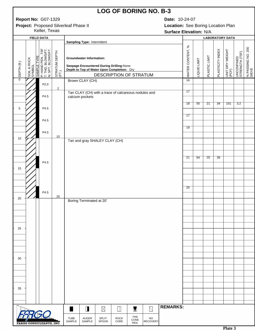
0
5
10
15
20
25
30
35
P2.0
P4.5
P4.5
P4.5
P4.5
P4.5
P4.5
2
10
20
Brown CLAY (CH)
Tan CLAY (CH) with a trace of calcareous nodules andcalcium pockets
Tan and gray SHALEY CLAY (CH)
Boring Terminated at 20'
16
17
18
17
19
21
20
55
64
21
25
34
39
101 3.2
LOG OF BORING NO. B-3Report No: G07-1329 Date: 10-24-07Project: Proposed Silverleaf Phase II
Keller, TexasLocation: See Boring Location PlanSurface Elevation: N/A
REMARKS:
TUBESAMPLE
AUGERSAMPLE
SPLIT-SPOON
ROCKCORE
THDCONEPEN.
NORECOVERY
DEP
TH (f
t.)
FIELD DATA
SOIL
& R
OC
KSY
MBO
LSA
MPL
E TY
PEP
: HA
ND
PE
N.,
TSF
T: T
HD
, BLO
WS
/FT.
N: S
PT, B
LOW
S/FT
.
STR
ATU
M D
EPTH
(FT.
)
DESCRIPTION OF STRATUM
Sampling Type: Intermittent
Groundwater Information:
Seepage Encountered During Drilling:NoneDepth to Top of Water Upon Completion: Dry
WAT
ER C
ON
TEN
T, %
LABORATORY DATA
LIQ
UID
LIM
IT
PLAS
TIC
LIM
IT
PLAS
TIC
ITY
IND
EX
UN
IT D
RY
WE
IGH
T(P
CF)
UN
CO
NFI
NED
STR
ENG
TH (T
SF)
% P
ASSI
NG
NO
. 200
SIEV
E
Plate 3

0
5
10
15
20
25
30
35
P0.5
P4.5
P4.5
P4.5
P4.5
P4.5
P4.5
2
8
20
Brown CLAY (CH) with sandy clay seams and a trace ofcoarse sand
Tan CLAY (CH) with a trace of calcareous nodules andcalcium pockets
Tan and gray SHALEY CLAY (CH)
Boring Terminated at 20'
16
16
18
22
23
22
21
59 23 36
LOG OF BORING NO. B-4Report No: G07-1329 Date: 10-24-07Project: Proposed Silverleaf Phase II
Keller, TexasLocation: See Boring Location PlanSurface Elevation: N/A
REMARKS:
TUBESAMPLE
AUGERSAMPLE
SPLIT-SPOON
ROCKCORE
THDCONEPEN.
NORECOVERY
DEP
TH (f
t.)
FIELD DATA
SOIL
& R
OC
KSY
MBO
LSA
MPL
E TY
PEP
: HA
ND
PE
N.,
TSF
T: T
HD
, BLO
WS
/FT.
N: S
PT, B
LOW
S/FT
.
STR
ATU
M D
EPTH
(FT.
)
DESCRIPTION OF STRATUM
Sampling Type: Intermittent
Groundwater Information:
Seepage Encountered During Drilling:NoneDepth to Top of Water Upon Completion: Dry
WAT
ER C
ON
TEN
T, %
LABORATORY DATA
LIQ
UID
LIM
IT
PLAS
TIC
LIM
IT
PLAS
TIC
ITY
IND
EX
UN
IT D
RY
WE
IGH
T(P
CF)
UN
CO
NFI
NED
STR
ENG
TH (T
SF)
% P
ASSI
NG
NO
. 200
SIEV
E
Plate 4
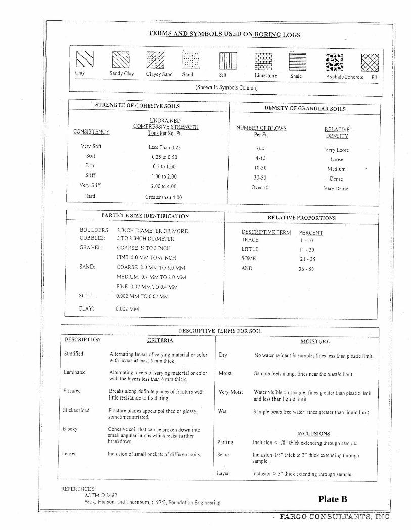
Plate B

Fargo Report No. G07-1329 FARGO CONSULTANTS, INC. FARGO CONSULTANTS, INC.
Geotechnical Engineering · Construction Materials Testing · Environmental Services
www.dallasfargo.com
APPENDIX

Fargo Report No. G07-1329 FARGO CONSULTANTS, INC. FARGO CONSULTANTS, INC.
Geotechnical Engineering · Construction Materials Testing · Environmental Services
www.dallasfargo.com
RECOMMENDED SPECIFICATIONS FOR CONTROLLED EARTHWORK ON HOUSING AND URBAN DEVELOPMENT PROJECTS
Site Preparation
All trees, stumps, brush, abandoned structures, foundation, roots, vegetation, debris, loose material, abandon
pipes, tree roots, etc. should be properly removed and discarded. Undesirable materials to be removed
include any fill encountered within the construction areas during excavations that was not placed under
compaction control.
To the extent practical, it is recommended that trees scheduled for removal in the area of proposed slab
foundations, be removed as far in advance of slab construction as possible. This is recommended as a
positive approach to restore a more favorable moisture equilibrium within the materials placed which will, in
turn, tend to reduce the potential for greater than anticipated post-construction ground movements. Root
balls should be removed, and the soils placed in these areas should be placed and compacted as per
recommendations discussed in the following sections.
Site Grading
The site grading plans and construction should strive to achieve positive drainage around the foundations,
structures, and flatwork to avoid excessive differential movements below slab. Preferably, the final grade
around the foundation and slabs should slope downward a minimum of 10 inches within 10 feet. This slope
should provide for proper positive drainage and to allow for post-construction heave of subgrade soils
beyond the foundations.
Final grades for cut or fill slopes, should not be steeper than 4 horizontal to 1 vertical. Steeper slopes or
slopes in critical areas (in close proximity to foundation) should be evaluated on a site-specific basis. In areas
where cut and fill slopes are to be steeper than 5 horizontal to 1 vertical, slab foundations preferably should
be located away form the crest of slopes a minimum distance of 10 feet or equal to the slope height,
whichever is grater.
Scarifying Area to be filled
Prior to placement of fill, the stripped surface shall be scarified to a depth of at least 6 inches. The intent is
to provide a surface with no features in order to have uniform compaction using proper equipment.
Compacting Area to be Filled
After the area to be filled is cleared and scarified, the subgrade shall be brought to proper moisture content.
On-site soil materials used as fill should be compacted in accordance with recommendations provided in this
report.

Fargo Report No. G07-1329 FARGO CONSULTANTS, INC. FARGO CONSULTANTS, INC.
Geotechnical Engineering · Construction Materials Testing · Environmental Services
www.dallasfargo.com
Fill Materials
On-site soils are suitable to be used as random fill. Off-site soils used as fill should be clean material. Fill
should not contain roots, vegetation or any other undesirable matter, and should not have any rocks larger
than six (6) inches in diameter.
Mixing of Fill Lifts and Benching
The fill material should be placed in uniform loose lifts not exceeding 8 inches in thickness. Each layer
should be thoroughly mixed during the spreading to ensure the uniformity of the lift. The fill should be
moisture conditioned and compacted in accordance with recommendations provided in the following
sections.
In areas where new fill is placed over sloping ground (slope steeper than 5 horizontal to 1 vertical), it is
recommended that the new fill be “tied in” to the underlying soils. It is recommended that benches with a
horizontal distance of 3 to 10-foot (depending on the steepness of the slope) be provided so that the new fill
can be placed and compacted in level lifts that are tied in to the existing soils along the slope. Fill placed
along the slope should be placed in uniform loose lifts of no greater than 10 inches. The fill should be
compacted to a minimum of 95 percent of standard Proctor maximum dry density (ASTM D 698).
Moisture Content
Material used as random fill shall be compacted at the appropriate moisture content, as described in the main
body of this report.
Compaction of Fill Lifts
Compaction equipment should be of appropriate type, capable of compacting fill layers to the specified
density. Compaction of each lift shall be accomplished with the material at the specified moisture content
and shall be continuous over its entire area.
Amount of Compaction
After each fill lift has been placed, moisture conditioned, mixed, and spread evenly, the fill shall be
thoroughly compacted to the specified density. In general, materials used as random fill shall be compacted
to between 93 and 98 percent of standard Proctor maximum dry density (ASTM D 698).
Field Density
Field density tests shall be performed by qualified geotechnical personnel. Density tests shall be taken in the
compacted material below the disturbed surface. If the material fails to meet the specified density, the failed
area shall be reworked as necessary to obtain the specified moisture and compaction.

Fargo Report No. G07-1329 FARGO CONSULTANTS, INC. FARGO CONSULTANTS, INC.
Geotechnical Engineering · Construction Materials Testing · Environmental Services
www.dallasfargo.com
Tree Areas
Prior to the construction of slab foundations, special considerations should be given to the building pad areas
that previously contained trees or trees are planned to be removed. Trees in general will remove moisture
from soil. It is possible that subgrade soils in tree areas could be in a dry condition at the time of
construction, having greater potential for magnitude of vertical movements as discussed in this report. This
condition could cause localized excessive heave below foundation where trees previously existed. Therefore,
it is recommended that soils within the lateral and vertical distance of the root zone be removed and replaced
with on-site soils. Fill soils placed in these areas should have proper moisture, placed and compacted in
accordance with the recommendations discussed previously in the above sections.
Drainage Ditches
Where drainage ditches are to be filled in the areas of slab foundation and flatwork, then prior to fill
placement all organic materials and soft soils should be excavated to expose firm stable materials. The
exposed subgrade should be proofrolled to detect any soft materials still in place. Soft soils, if noted, should
be removed and replaced with on-site soils that are placed and compacted in accordance with the
recommendations discussed previously in the above sections.
Slope Control
Embankment slopes should not be steeper than four (4) horizontal to one (1) vertical for either fill or cut
slopes. Any slope, existing or proposed, exceeding three (3) feet in height should incorporate stabilization
methods to include erosion control, embankment stabilization and other slope control measures as required
by the slope control specialist.
Supervision
The Geotechnical Engineer should observe the earthwork construction at periodic intervals with adequate
frequency to enable him to provide a professional opinion that all subgrade preparation, fill placement and
related work were completed in accordance with the accepted specification.