preliminary design report for the civil …cape-eaprac.co.za/projects/kny207 ethembeni...
TRANSCRIPT

PRELIMINARY DESIGN REPORT FOR THE CIVILENGINEERING SERVICES TO SERVE THE INFORMAL
SETTLEMENT AREA OF:
ETHEMBENI, KNYSNA
AUGUST 2012
PREPARED BY:
SIKHULILE ENGINEERS (PTY) LTD
26 High Street
PO Box 3694
Knysna
6571
TEL: 044 – 3827680
FAX: 044 – 3825396
EMAIL: [email protected]
PREPARED FOR:
THE MANAGER: INTERGRATED HUMANSETTLEMENT
KNYSNA MUNICIPALITY
PO Box 21
KNYSNA
6570
CONTACT PERSON: ETIENNE BRUWER

2
CONTENTS
1. Executive summary
2. Introduction
3. Site description3.1 Existing infrastructure3.2 Topography3.3 Informal structures
4. Civil Engineering Services4.1 Water4.2 Sewerage4.3 Solid waste4.4 Roads & stormwater
4.4.1 Access4.4.2 Road pavement4.4.3 Stormwater drainage
4.5 Availability of bulk services4.6 Cost estimate
5. Land Rehabilitation and Top Structures
Attachments:
Annexure A Proposed Site Development by VPMCivil Engineering Drawings 140 – P – 01: Water reticulation 140 – P – 02: Sewer reticulation 140 – P – 03: Roads & Stormwater 140 – P – 04: Sewer long sections 140 – P – 05: Road long sections
Annexure B Land Rehabilitation & Top Structure Drawings 140 – P – 06: 40 m² Top Structure: Type 1 140 – P – 07: Type 1: Raft foundation 140 – P – 08: 40 m² Top Structure: Type 2 140 – P – 09: Type 2: Raft foundation 140 – P – 10: Bulk Earthworks: Scenario A 140 – P – 11: Bulk Earthworks: Scenario B 140 – P – 12: Bulk Earthworks: Scenario C 140 – P – 13: Bulk Earthworks: Scenario D
Annexure C 40 m² Top Structure: Cost Estimate & specifications

3
1. EXECUTIVE SUMMARY
Ethembeni is a relative large development node located across the road from theMasifunde library and new Day Care Centre. It has been used for the purposed ofinformal residential units for many years identified for the purpose of subsidized lowincome housing.
There are currently approximately 130 informal structures and a church building on thesite and the initial planning provides for the sub-division of 180 single residential erven.
The current level of service is limited to standpipes, portable toilets and partialwaterborne sewage reticulation, which have in the meantime been provided throughoutthe site by the Knysna Municipality.
The site is relatively steep in sections, typical of most areas in the northern areastherefore costly to service but nevertheless justifiable considering the land availabilityconstraints in Knysna within close proximity to municipal bulk services, schools andpublic transport (the site borders the main bus route). Some sections of the proposedinternal road network require considerable cut depths of up to two meters andassociated retaining structures. Vehicle access will be limited to erven with directaccess to internal roads only.
However, the Municipality has indicated to us that in general it has limited capacity toprovide additional bulk infrastructure services, particular sewerage treatment capacity,to service new developments in the whole of Knysna Greater Area and not particularlyfor this specific site in isolation.
It is nevertheless our opinion that the effluent generated by the additional 120 housingunits is relatively moderate and unlikely to have any significant impact on the existingbulk services, although the existing pumpstation will have to be upgraded to deal withthe additional effluent.
The total estimated cost including services and top structures is R 23 680 379-20excluding Value Added Tax.
Provision of services R 6,375,146.80 Top structures & Platforms R 18,295,232.40 Total R 24,670,379.20 Cost per stand R 137,057.66

4
2. INTRODUCTION
Sintec Engineering Consultants were instructed by the Knysna Municipality to submitthis report for the purpose of the N6 application currently being processed by SSI.
The report includes a general overview identifying the availability of bulk services,preliminary internal design of civil engineering services and respective cost estimate.
The extent of the development is depicted in the Locality Plan enclosed in the attachedappendix as Annexure A. It consists of the consolidation and subdivision of variouserven in order to provide180 single residential erven (refer to VPM Planning’s report).
3. SITE DESCRIPTION
3.1 Existing infrastructure
The area earmarked for subdivision is currently used as an informal settlement. Basicservices, including limited waterborne sewage reticulation and water reticulation hasbeen installed.
The sewage discharges into a pumpstation located on the western boundary of the sitewhich in turn pumps upstream into another pumpstation located next to the Masifundelibrary.
Existing roadways are generally in poor condition.
Approximately 60 erven are currently serviced mainly along the entrance road andchurch site.
3.2 Topography
The areas identified for subdivision are generally very steep, Large sectors of the site are characterized with gradients of approximately 30%
or steeper (refer to slope analysis drawing produced by VPM), The eastern section of the proposed subdivision (east and north of the church
site) is bisected by a natural watercourse flowing steeply in a northerly direction, The western area (west of the church site) is also bisected by a natural water
course flowing in a northwesterly direction.
3.3 Informal structures
There are currently approximately 130 informal structures in this area, most of whichwill eventually have to give way to formalized housing units.

5
4. CIVIL ENGINEERING SERVICES
Calculations are based on the guidelines for Human Settlements Planning & Design forthe estimation of water and sewerage services.4.1 WATER
The water reticulation system will consist of the following (Refer drawing 140 – P – 01):
75mm & 110 mm ø Class 9 uPVC mainline and shall comply with SABS 966, All water lines will comply with the requirements of SABS 1200 L: Medium
Pressure Pipe lines, All Flanges and accessories shall be drilled to comply with BS 4504, table 16/11
for working pressure of 1600 kPa, All cast iron fittings shall be Rilsan coated and after installation all fittings,
specials, valves and the appurtenant nuts and bolts shall be covered with aprotective paste (Densopaste or similar) and thereafter the smeared surfacesshall be wrapped in an impregnated tape (Densotape or similar). All bolts andnuts shall be stainless steel as per SABS,
Isolating valves shall be class 10 resilient seal valves, epoxy coated, doubleSocketed, anti-clockwise closing, with capped top and non-rising spindle,
Fire hydrant will be the London Round Thread Type, All pipe lines will be bedded on a selected granular material. These materials
shall comply to Class B bedding and SABS 1200 LB and shall be non-cohesiveand free-draining.
Water demand generated by the proposed development:
180 erven @ 600l/day/erf = 108 m³/day (1.25 l/s), Peak Demand (PF = 5) = 6.25 l/sec
Storage requirements:
Domestic: 48 hrs = 216.0 m³ Fire flow (moderate risk) = 57.6 m³ Total storage required = 273.6 m³
Water supply will be initially extracted from the existing 90mm Ø main. There ishowever a newly proposed 200 mm Ø connection point situated at the Masifunde nodethat would serve as the permanent connection to serve this area.
4.2 SEWERAGE
This system of pipes collects effluent water, which may contain solids in suspensionfrom the individual sites, to two (2) newly proposed sewer pump stations.
These pumpstation would discharge into the existing pipe network as shown ondrawing 140 – P – 02.
The proposed system would consist of the following:

6
160 mm ø uPVC Solid Wall SABS 791 Class 34 400 kPA or similar spigot &socket pipes for mainline,
110 mm ø uPVC Solid Wall SABS 791 Class 34 400 kPA or similar spigot &socket pipes for residential connections, All sewer mains will have a minimumgrade of 1 in 100,
Internal drainage will have a minimum grade of 1 in 60, Sewer manholes will be 1.05 m ø ROCLA or similar approved precast concrete
rings with concrete covers and frames. Medium duty covers for roadside vergesand non trafficked areas and heavy duty concrete covers and frames will bespecified for trafficked areas. It is recommended that all the joints on the precastrings be sealed for water ingress with a 100 x 1 mm wide PolyurethaneBandage,
All pipe lines will be bedded on a selected granular material. These materialsshall comply to Class B bedding and SABS 1200 LB and be non-cohesive andbe free-draining. Initial tests have shown that the on-site material would besuitable for selected fill,
The new pumpstations will be equipped with two submersible pumps and a sump (“wetwell system”). The size and depth of the sump will be sized to accommodate six hoursof emergency storage based on the average dry weather flow (ADWF) which reachesthe pumpstation.
In the hydraulic design both minor and major losses will be taken into account.Deposition of solids must be prevented by maintaining a velocity of at least 0.7 m/s.Very high velocities should be avoided in order to limit friction losses. For this reason amaximum of 2.5 m/s is prescribed.
No allowance for emergency power failure has been provided.
The following aspects will make up this system:
Two (2) Flyghts’ or similar approved submersible pumps. These pumps will becapable of pumping solids of up to 85 mm ø and will be equipped to be able toself cleanse the bottom of the well. These small pumps are less likely to blockas they will be fitted with low efficiency vortex impellers,
Starting and stopping of the pumps will automatically occur by predeterminedwater levels in the sump. This will be done using float controls or electrodes.The controls will be placed as to restrict pump starts to between 4 to 8 per hourfor the submersible pumps,
Provision will be made for controlling pumps manually during emergencies andalso for maintenance purposes.

7
Effluent
Using the Harmon Formula to determine the peak factor (calculated at 3.8) and anaverage of 50% infiltration we summarize as follows:
ADWF: 90 m³ / day (1.04 l/s), PWWF: 684 m³ / day (7.92 l/s),
4.3 SOLID WASTE
Average solid waste per household = 0.12 m³ / week, Total solid waste = 21.6 m³ / week.
4.4 ROADS & STORMWATER
4.4.1 Access
The proposed access to the site is the existing entrance from the bus route oppositethe new Day Care Centre as indicated in VPM Planning’s layout and our road layoutplan.
4.4.2 Roadways (refer to Drg no. 140 – P - 03)
The proposed width of the internal roads is 4.50 m consisting of two structural layersand concrete paving blocks. It may be necessary to import rockfill on the lowersections of the road due to geotechnical characteristics.
The layer works will be designed for the anticipated traffic loads.
Bottom layer: 150 mm thick in-situ layer compacted to 95 % mod. ASSHTO; Sub-base layer: 150 mm thick G7 layer imported from commercial sources and
compacted to 95 % mod. AASHTO, Base layer: 150 mm thick G5 layer imported from commercial sources
compacted to 98 % mod AASHTO, The wearing surface of all the roads will consist of segmented paving blocks, 65
mm thick and placed on 25mm thick bedding sand. Edges will be constructedwith a concrete edge kerbing,
The minimum road cross fall will be 2.5% and be mostly sloping against thenatural gradient of the site. A minimum longitudinal fall of 0.5% shall be adheredto.
Road gradients vary from flat along the bottom section up to a maximum of 18%in Road 2.
4.4.3 Stormwater drainage
Provision for effective stormwater drainage should be made by means of acombination of underground pipes and concrete lined V-drains running parallel to theroadways and discharging into the natural two natural water courses bisecting the siteinto strategically placed energy dissipater.

8
4.5 Bulk servicesAlthough municipal water and sewer connection points are available in the proximity ofthe site, the Municipality’s Technical Department has indicated that currently they donot have the additional capacity to accommodate additional sewage in their treatmentworks.
Mr. R Parry has further informed us that SSI has been appointed by the Municipalityfor the evaluation and administration of bulk supply issues.
4.6 Cost Estimate
These civil Engineering costs are based on current (August 2012) rates receivedthrough contracts of similar nature and is for the complete servicing of the 180residential stands:
We highlight the following pertaining the costs (All costs exclude VAT):
Total cost for the provision of services = R 6,375,146.80 Estimated cost per Erf excl Vat = R 35,417.48 Includes for 10% contingencies Includes for Professional fees Excludes any bulk infrastructure contributions and upgrading.
9
5. TOP STRUCTURES AND LAND REHABILITATION
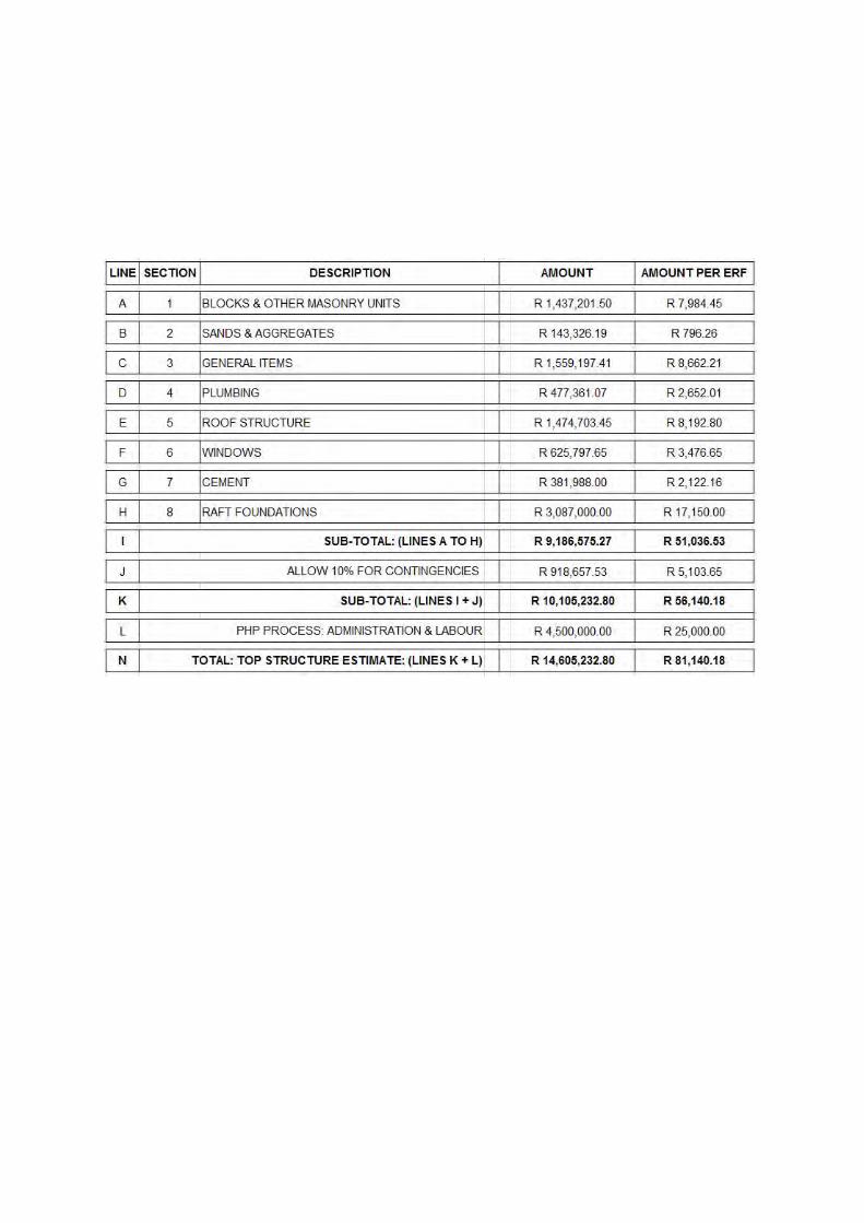
Assuming that the top structures will be administered in terms of the PHP housingscheme, the cost of implementation is tabled below: (A detailed housing materialbreakdown and specification is included part Annexure C):
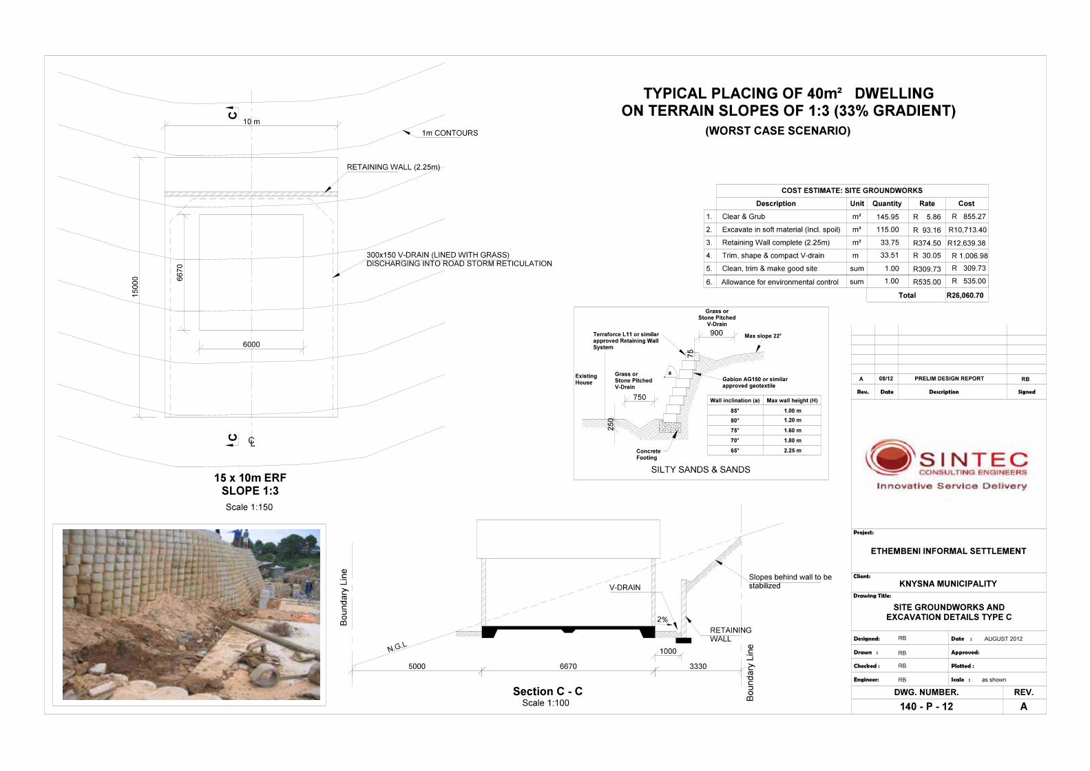
Due to the steep topography of the terrain, a considerable number of platforms andretaining walls are envisaged. In order to arrive at an average cost per stand we haveconsidered different options as these are included part Annexure C.
The total estimated cost for land rehabilitation and top structures:
Land rehabilitation (platforms) = ± R 20,500.00 Complete top structure = ± R 81,140.18 Total cost per top structure = ± R 101,640.18 Total for 180 top structures = ± R18,295,232.40

10