prefetching in a texture cache architecture · prefetching in a texture cache architecture homan...
TRANSCRIPT
Prefetching in a Texture Cache Architecture
Homan Igehy Matthew Eldridge Kekoa Proudfoot
Computer Science Department Department of Electrical Engineering Department of Electrical Engineering
Stanford University
AbstractTexture mapping has become so ubiquitous in real-time graphicshardware that many systems are able to perform filtered texturingwithout any penalty in fill rate. The computation rates availablein hardware have been outpacing the memory access rates, andtexture systems are becoming constrained by memory bandwidthand latency. Caching in conjunction with prefetching can be usedto alleviate this problem.
In this paper, we introduce a prefetching texture cache archi-tecture designed to take advantage of the access characteristics oftexture mapping. The structures needed are relatively simple andare amenable to high clock rates. To quantify the robustness ofour architecture, we identify a set of six scenes whose texturelocality varies over nearly two orders of magnitude and a set offour memory systems with varying bandwidths and latencies.Through the use of a cycle-accurate simulation, we demonstratethat even in the presence of a high-latency memory system, ourarchitecture can attain at least 97% of the performance of a zero-latency memory system.
CR Categories and Subject Descriptors: I.3.1 [ComputerGraphics]: Hardware Architecture.
1 INTRODUCTIONTexture mapping has become ubiquitous in real-time graphicshardware over the past few years. The accelerators found in everysegment of the market, from the consumer level to the graphicssupercomputer level, have on-chip support for performing thecostly operations associated with texture mapping. The use oftexture mapping is so pervasive that many systems are built toperform the necessary operations without any penalty in fill rate.
Texture mapping is expensive both in computation and mem-ory accesses. Continual improvement in semiconductor technol-ogy has made the computation relatively affordable, but memoryaccesses have remained troublesome. Several researchers haveproposed and demonstrated texture cache architectures which canreduce texture memory bandwidth. Hakura and Gupta examinedifferent organizations for on-chip cache architectures which areuseful for exploiting locality of reference in texture filtering, tex-
ture magnification, and to a limited extent, repeated textures [5].Cox, Bhandari, and Shantz extend this work to multi-level cach-ing [3]. They demonstrate that on-chip caches in conjunction withlarge off-chip caches can be used to exploit all of the aforemen-tioned forms of texture locality as well as inter-frame texture lo-cality. Thus, memory bandwidth requirements can be dramati-cally reduced for scenes in which the working set of a frame fitsinto the off-chip cache.
A second troublesome point about texture memory access(which is not addressed by Hakura or Cox) is the high latencies ofmodern memory systems. In order to address this problem, sev-eral systems have been described that make use of large pipelineswhich prefetch the texel data [1, 7, 11]. Two of the systems [1, 7]do not use any explicit caching, although their memory systemsare organized for the reference patterns of texture filtering, butone system [11] does employ prefetching as well as two levels ofcaching, one of which holds compressed textures. However, thealgorithm which combines the prefetching with the caching is notdescribed. Several other consumer-level architectures exist whichundoubtedly utilize some form of prefetching, possibly withcaching. Unfortunately, none of these algorithms are described inthe literature.
In this paper, we introduce a texture architecture which com-bines prefetching and caching. Our architecture is designed totake advantage of the peculiar access characteristics of texturemapping. The structures needed for implementing the prefetchingalgorithm are relatively simple, thus making them amenable to thehigh clock rates associated with texture mapping. To quantify therobustness of our prefetching texture cache architecture, we iden-tify a set of six scenes whose texture locality varies over nearlytwo orders of magnitude and a set of four memory systems withvarying bandwidths and latencies. Through the use of a cycle-accurate simulation, we demonstrate that the texture prefetchingarchitecture can successfully hide nearly all of the latency of thememory system over a wide range of configurations. The spaceoverhead of this architecture is reasonable, and the resulting tex-ture system is always able to attain at least 97% of the perform-ance of a zero-latency memory system.
2 MIP MAPPINGTexture mapping, in its most basic form, is a process by which a2D image is mapped onto a projected screen-space triangle underperspective. This operation amounts to a linear transformation in2D homogeneous coordinates. The transformation is typicallydone as a backward mapping—for each pixel on the screen, thecorresponding coordinate in the texture map is calculated. Thebackward mapped coordinate typically does not fall exactly onto asample in the texture map, and the texture may be minified ormagnified on the screen. Filtering is applied to minimize theeffects of aliasing, and ideally, the filtering should be efficient andamenable to hardware acceleration.
{homan,eldridge,kekoa}@graphics.stanford.edu
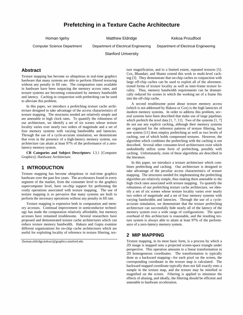
Mip mapping [12] is the filtering technique most commonlyimplemented in graphics hardware. In mip mapping, an imagepyramid is constructed from the base image which serves as thebottom of the pyramid. Each successive level of the pyramid isconstructed by resampling the previous level of the pyramid byhalf in each dimension, as illustrated in Figure 1. For eachscreen-space fragment, the rasterization process computes a tex-ture coordinate and an approximate texel-to-pixel ratio (alsoknown as the level-of-detail value). This ratio is used to computethe two closest corresponding mip map levels, and a bilinear in-terpolation is performed on the four nearest texels in each of thetwo adjacent levels. These two values are then combined withlinear interpolation based on the level-of-detail value, and theresulting trilinearly interpolated sample is passed to the rest of thegraphics pipeline. If a fragment falls beyond either end of the mipmap pyramid, the algorithm performs bilinear filtering on the oneclosest level of the mip map.
The popularity of mip mapping can be attributed to three char-acteristics. First, mip mapping reduces many aliasing artifacts.Although it is by no means an ideal filter, especially since it oftenblurs excessively, the results are quite acceptable for interactiveapplications. Second, the computational costs of mip mapping,though by no means cheap, are reasonable and fixed for eachfragment. Finally, mip mapping is efficient with respect to mem-ory. The additional space required for the pyramid representationis only one-third the space occupied by the original image. Fur-thermore, because the level-of-detail computation is designed tomake one step in screen space correspond to approximately onestep in the appropriate mip map level, the memory access patternof mip mapping is very coherent.
3 CACHING AND PREFETCHINGFor the past few decades, many aspects of silicon have been expe-riencing exponential growth. However, not all aspects havegrown at the same rate. While memory density and logic densityhave seen tremendous growth, logic speed has experienced moremoderate growth, and memory speed has experienced slightgrowth. These factors have made the cost of computation on achip very cheap, but memory latency and bandwidth sometimeslimit performance. Even with the advent of memory devices withhigh-speed interfaces [4], it is easy to build a texturing system thatoutpaces the memory it accesses. The problem of directly ac-cessing DRAM in a texture system is aggravated by the fact thatmemory devices work best with transfers that do not match theaccess patterns of texture mapping: DRAM provides high band-width when moving large contiguous blocks of memory, but afragment’s texture accesses typically consist of several small non-contiguous memory references.
An obvious solution to this problem is caching. Many issuesare resolved by integrating a small amount of high-speed, on-chipmemory organized to match the access patterns of the texturesystem. According to our measurements (detailed in Section 5.1)as well as data found in other literature [3, 5], it is quite reason-able to expect miss rates on the order of 1.5% per access. Manytexture systems are capable of providing the computation for atrilinearly mip mapped fragment on every clock cycle. Thus,because there are eight texture accesses per cycle, the per-fragment texel miss rate is 12%. Even if these misses could beserviced in a mere 8 cycles each, a calculation of the averagememory access time shows that overall performance is cut in half.Clearly, this is not acceptable.
While caching can alleviate the memory bandwidth problem, itdoes not solve the memory latency problem. The latency problemwith relation to texture caching is a special one. In current inter-active graphics interfaces, texture accesses are read-only for largeamounts of time, and address calculation for one texture access isnever dependent on the result of another texture access. Thus,there are no inherent dependencies to limit the amount of latencythat can be covered. This means that a prefetching architectureshould be capable of handling arbitrary amounts of latency.
3.1 Traditional PrefetchingIn the absence of caching, prefetching is very easy. When afragment is ready to be textured, the memory requests for theeight texel accesses are sent to the memory system, and the frag-ment is queued onto a fragment FIFO. When the replies to thememory requests arrive, the fragment is taken off the FIFO, andthe fragment is textured. The time a fragment spends in the FIFOis equal to the latency of the memory system, and if the FIFO issized appropriately, fragments may be processed without everstalling. For greater efficiency, part of the fragment FIFO canactually be a fragment processing pipeline [1, 7]. Note that thisnon-caching prefetching architecture assumes that memory repliesarrive in the same order that memory requests are made, and thatthe memory system can provide the required bandwidth withsmall memory requests.
One straightforward way to combine caching with prefetchingis to use the architecture found in traditional microprocessors thatuse explicit prefetch instructions. Such an architecture consists ofa cache, a fully associative prefetch address buffer, and a memoryrequest buffer. A fragment in such a system is processed as fol-lows: first, the fragment’s texel addresses are looked up in thecache tags, and the fragment is stored in the fragment FIFO.Misses are forwarded to a prefetch buffer that is made fully asso-ciative so that multiple misses to the same memory block can becombined. New misses are queued in the memory request bufferbefore being sent to the memory system. As data returns from thememory system, it is merged into the cache. When a fragmentreaches the head of the fragment FIFO, the cache tags are checkedagain, and if all of the texels are found in the cache, the fragmentcan be filtered and textured. Otherwise, additional misses aregenerated, and the system stalls until the missing data returnsfrom memory. Fortunately, the architecture works even in con-junction with an out-of-order memory system.
There are three problems with using the traditional microproc-essor prefetch architecture for texture mapping. First, if the prod-uct of the memory request rate and the memory latency beingcovered is large compared to the size of the caches utilized, aprefetched block that is merged into the cache too early can causeconflict misses. Second, in order to support both reading and
Level 0
Level 2
Level 3
ReconstructedSample Level 1
Figure 1: Mip Mapping. An image is filtered recursivelyinto quarter-sized images. Trilinear interpolation recon-structs a sample by linearly interpolating between two adja-cent levels of the mip map, each of which is sampled withbilinear filtering on the four closest texels in that level of themip map.
prefetching of texels at the full fragment rate, tag checks must beperformed at twice the fragment rate, increasing the cost of the taglogic. Finally, as the product of the memory request rate and thememory latency increases, the size (and therefore the associativ-ity) of the prefetch buffer must be increased proportionally.
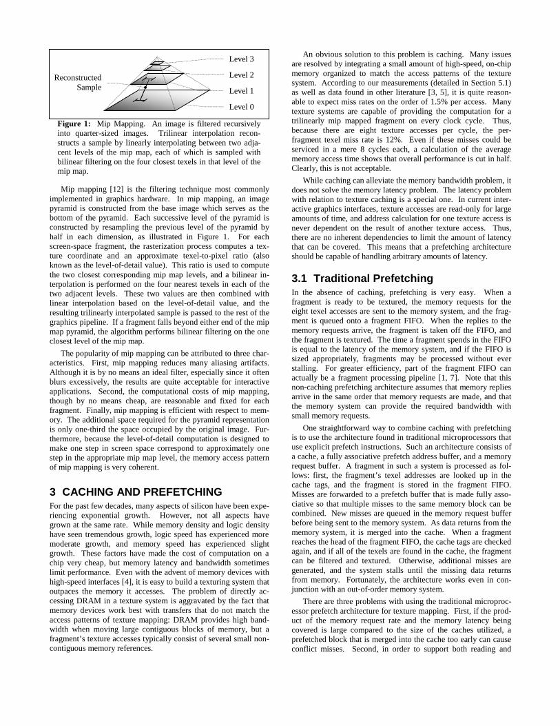
3.2 A Texture Prefetching ArchitectureWhile some of the problems with the traditional microprocessorprefetching architecture can be alleviated, we have designed acustom prefetching architecture that takes advantage of the specialaccess characteristics of texture mapping. This architecture isillustrated in Figure 2. Three key features differentiate this archi-tecture from the one described in Section 3.1. First, tag checksare separated in time from cache accesses, and tag checks areperformed only once per texel access. Second, because the cachetags are only checked once and always describe the future con-tents of the cache, a fully associative prefetch buffer is notneeded. And third, a reorder buffer is used to buffer memoryrequests that come back earlier than needed.
The architecture processes fragments as follows. As eachfragment is generated, each of its texel addresses is looked up inthe cache tags. If a tag check reveals a miss, the cache tags areupdated with the fragment’s texel address immediately and the
address is forwarded to the memory request FIFO. The cacheaddresses associated with the fragment are forwarded to the frag-ment FIFO and are stored along with all the other data needed toprocess the fragment, including color, depth, and filtering infor-mation. As the request FIFO sends requests for missing cacheblocks to the texture memory system, space is reserved in thereorder buffer to hold the returning memory blocks. This guar-antee of space makes the architecture robust and deadlock-free inthe presence of an out-of-order memory system. A FIFO can beused instead of the reorder buffer if responses from memory al-ways return in the same order as requests sent to memory.
When a fragment reaches the head of the fragment FIFO, itcan proceed only if all of its texels are present in the cache.Fragments that generated no misses can proceed immediately, butfragments that generated one or more misses must first wait fortheir corresponding cache blocks to return from memory into thereorder buffer. In order to guarantee that new cache blocks do notprematurely overwrite older cache blocks, new cache blocks arecommitted to the cache only when their corresponding fragmentreaches the head of the fragment FIFO. Fragments that are re-moved from the head of the FIFO have their corresponding texelsread from the cache and proceed onward to the rest of the texturepipeline.
Our simulated implementation can handle eight texel reads inparallel, consisting of two bilinear accesses to two adjacent mipmap levels. To support these concurrent texel reads, we organizeour cache tags and our cache memory as a pair of caches with fourbanks each. Adjacent levels of a mip map are stored in alternatingcaches to allow both mip map levels to be accessed simultane-ously. Data is interleaved so that the four accesses of a bilinearinterpolation occur in parallel across the four banks of the respec-tive cache. Cache tags are also interleaved across four banks in afashion that allows the tag checks for a bilinear access to occurwithout conflict. The details of this layout can be found in Figure3 of Section 5.
In order to make our architecture amenable to hardware im-plementation, we impose two limitations. First, the number ofmisses that can be added to the request FIFO is limited to onemiss per cache per cycle. Second, the number of cache blocksthat can be committed to the cache from the reorder buffer issimilarly limited to one block per cache per cycle. These commitsmatch up to the requests—groups of misses that are added to therequest FIFO together are committed to the cache together. Thismeans that each fragment may generate up to four groups ofmisses. Because our implementation can only commit one ofthese groups per cycle, a fragment that has more than one groupof misses will cause the system to stall one cycle for every groupof misses beyond the first.
4 ROBUST SCENE ANALYSISWhen validating an architecture, it is important to use benchmarksthat properly characterize the expected workload. Furthermore,when validating interactive graphics architectures, an architectshould look beyond averages due to various characteristics of thehuman perceptual system. For example, if a graphics systemprovides 60 Hz rendering for the majority of the frames, but everyonce in a while drops to 15 Hz for a frame, the discontinuity isdistracting, if not nauseating. In designing a system, the graphicsarchitect must evaluate whether or not sub-optimal performance isacceptable under bad-case conditions. Accordingly, a robust setof scenes that cover a broad range of workloads, from good-caseto bad-case, should be utilized to validate a graphics architecture.
TextureMemorySystem
FragmentFIFO
Tags
RequestFIFO
ReorderBuffer
Cache
Texels
OtherFragment
Data
TexelAddresses
OtherFragment
Data
Rasterizer
Texture Applicator
TextureFilter
MissAddresses
CacheBlocks
CacheAddresses
CacheAddresses
FilteredSamples
Figure 2: A Texture Prefetching Architecture.
4.1 Texture LocalityThe effectiveness of texture caching is strongly scene-dependent.For example, the size and distribution of primitives affect texturelocality. Texture locality is also affected by what we call thescene’s unique texel to fragment ratio. Every scene has a numberof texels that are accessed at least once; these texels are calledunique texels. Unless caches are big enough to exploit inter-framelocality (this requires several megabytes [3]), every unique texelmust be fetched at least once by the cache, imposing a lower limiton the required memory bandwidth. If we divide this number bythe number of fragments rendered for a scene, we can calculatethe unique texel to fragment ratio. Note that this value is depend-ent on the screen resolution. A good-case scene will have a lowratio, and a bad-case scene will have a high ratio. Ideally, thenumber of texels fetched by the caching architecture per fragmentwill be close to the scene’s unique texel to fragment ratio.
Three factors affect the unique texel to fragment ratio of ascene. First, when a texture is viewed under magnification, eachtexel gets mapped to multiple screen pixels, and the ratio de-creases. Second, when a texture is repeated across a surface, theratio also decreases. This temporal coherence can be exploited bya cache large enough to hold the repeated texture. Third, when amip map texture is viewed under minification, the ratio becomesdependent on the relationship between texel area and pixel area.This relationship is characterized by the level-of-detail value ofthe mip mapping computation that aims to keep the footprint of abackward-mapped pixel equal to the size of a texel in a mip maplevel. Although this value is normally calculated automatically,the application programmer may bias it in either direction, thusmodifying the scene’s unique texel to fragment ratio.
A more surprising effect that occurs even without biasing ischaracterized by the fractional portion of the level-of-detail value.The level-of-detail value determines the two levels of the mipmap from which samples are taken; the fractional portion is pro-portional to the distance from the lower, more detailed level.Given a texture mapped polygon that is parallel to the screen, afractional portion close to zero implies a texel area to pixel arearatio of nearly one in the lower mip map level and a quarter in theupper mip map level, yielding a texel to fragment ratio near 1.25.Likewise, a fractional portion close to one implies a texel area topixel area ratio of four in the lower mip map level and one in theupper mip map level, yielding a texel to fragment ratio near 5.The ratios are lower for polygons that are not parallel to thescreen. Normally, we expect a wide variation in the texel tofragment ratio due to the fractional portion of the level-of-detailvalue. However, most scenes exhibit worst-case behavior for
short amounts of time, and a few scenes exhibit worst-case be-havior for large amounts of time.
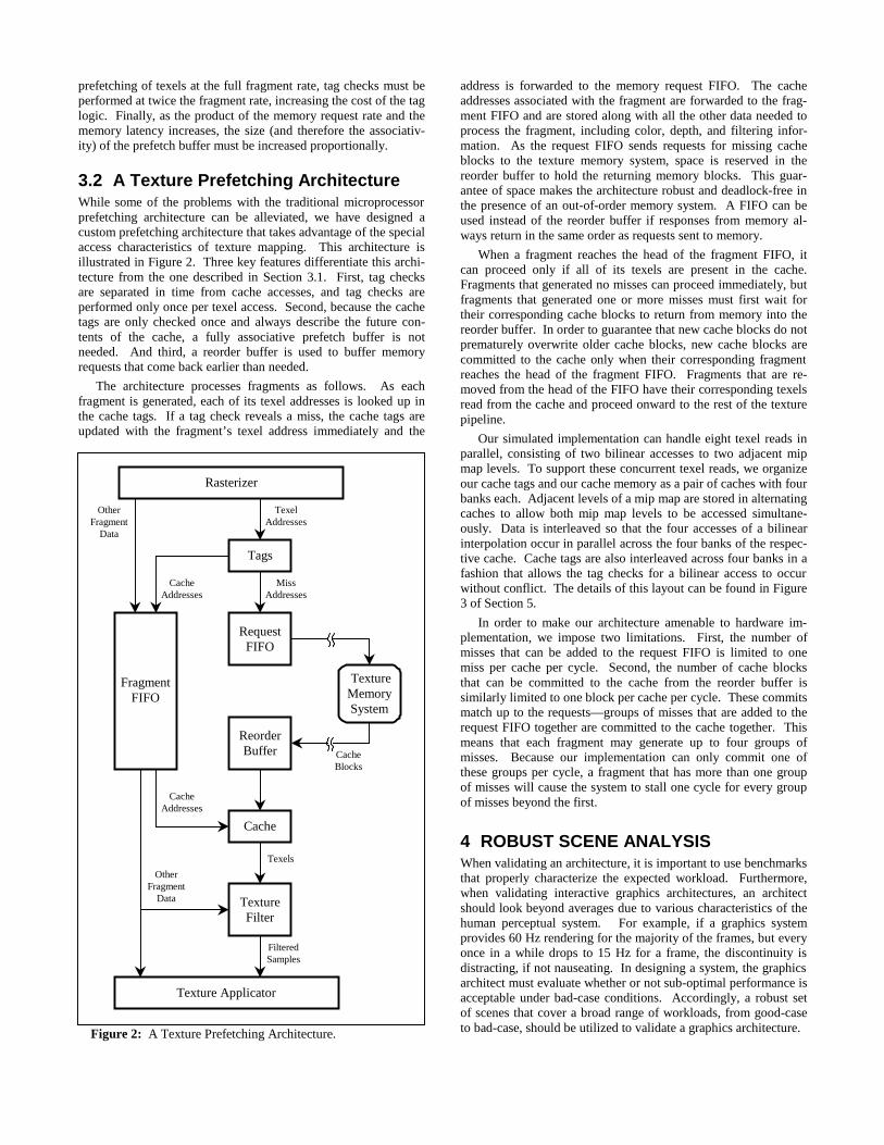
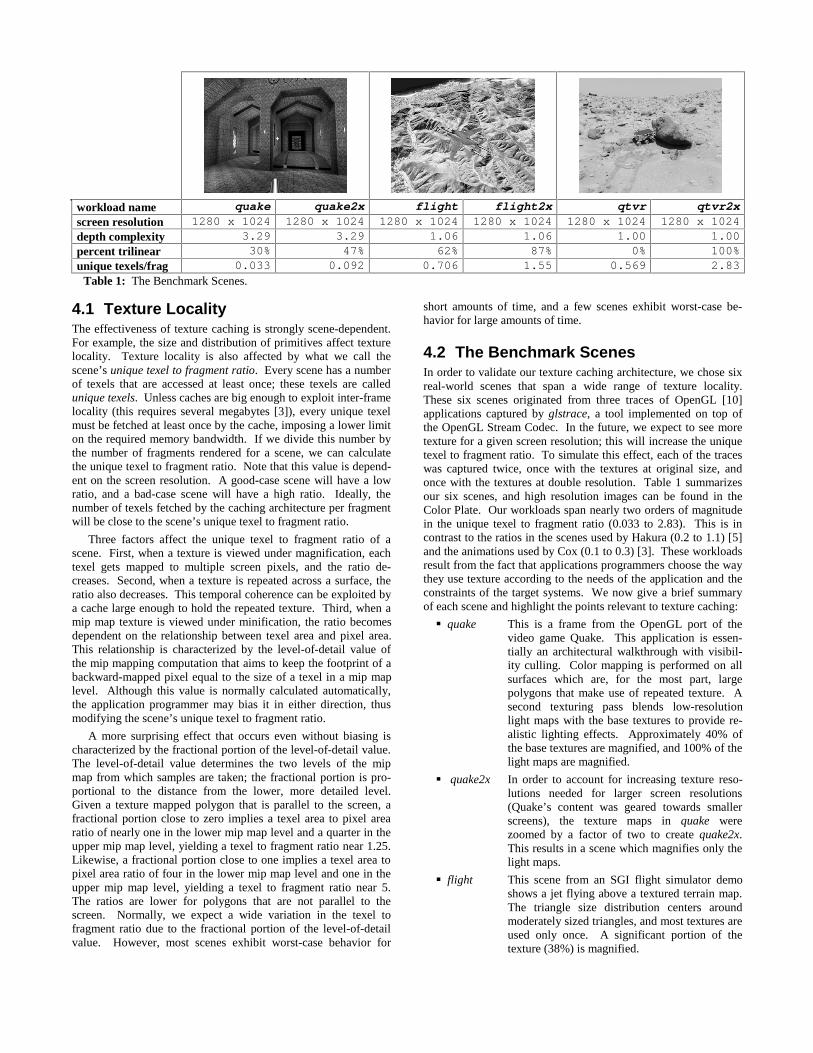
4.2 The Benchmark ScenesIn order to validate our texture caching architecture, we chose sixreal-world scenes that span a wide range of texture locality.These six scenes originated from three traces of OpenGL [10]applications captured by glstrace, a tool implemented on top ofthe OpenGL Stream Codec. In the future, we expect to see moretexture for a given screen resolution; this will increase the uniquetexel to fragment ratio. To simulate this effect, each of the traceswas captured twice, once with the textures at original size, andonce with the textures at double resolution. Table 1 summarizesour six scenes, and high resolution images can be found in theColor Plate. Our workloads span nearly two orders of magnitudein the unique texel to fragment ratio (0.033 to 2.83). This is incontrast to the ratios in the scenes used by Hakura (0.2 to 1.1) [5]and the animations used by Cox (0.1 to 0.3) [3]. These workloadsresult from the fact that applications programmers choose the waythey use texture according to the needs of the application and theconstraints of the target systems. We now give a brief summaryof each scene and highlight the points relevant to texture caching:
� quake This is a frame from the OpenGL port of thevideo game Quake. This application is essen-tially an architectural walkthrough with visibil-ity culling. Color mapping is performed on allsurfaces which are, for the most part, largepolygons that make use of repeated texture. Asecond texturing pass blends low-resolutionlight maps with the base textures to provide re-alistic lighting effects. Approximately 40% ofthe base textures are magnified, and 100% of thelight maps are magnified.
� quake2x In order to account for increasing texture reso-lutions needed for larger screen resolutions(Quake’s content was geared towards smallerscreens), the texture maps in quake werezoomed by a factor of two to create quake2x.This results in a scene which magnifies only thelight maps.
� flight This scene from an SGI flight simulator demoshows a jet flying above a textured terrain map.The triangle size distribution centers aroundmoderately sized triangles, and most textures areused only once. A significant portion of thetexture (38%) is magnified.
workload name quake quake2x flight flight2x qtvr qtvr2xscreen resolution 1280 x 1024 1280 x 1024 1280 x 1024 1280 x 1024 1280 x 1024 1280 x 1024depth complexity 3.29 3.29 1.06 1.06 1.00 1.00percent trilinear 30% 47% 62% 87% 0% 100%unique texels/frag 0.033 0.092 0.706 1.55 0.569 2.83
Table 1: The Benchmark Scenes.
� flight2x As texture systems become more capable ofhandling larger amounts of texture, applicationswill use larger textures to avoid the blurring arti-fact of filtered magnification. In flight2x, thetextures of flight were zoomed by a factor oftwo. This results in a scene which only magni-fies 13% of the texture.
� qtvr This scene comes from an OpenGL-basedQuickTime VR [2] viewer looking at a pano-rama from Mars. This huge panorama, whichmeasures 8K by 1K, is mapped onto a polygonalapproximation of a cylinder made of tall, skinnytriangles. Even though all of the texture is mag-nified, the lack of repeated texture keeps thenumber of unique texels per fragment high.
� qtvr2x The texture of qtvr was scaled up to 16K by 2K.This increases the number of unique texels ac-cesses by the scene since all the texture is mini-fied. Furthermore, the fractional portion of thelevel-of-detail value is always high in qtvr2x be-cause the panorama is viewed more or less head-on at just the wrong zoom value. Note that thesesame effects would occur if qtvr was run atquarter-sized screen resolution, and that qtvr2xis by no means a hand-tailored pathological
case. In fact, it was while gathering trace dataon qtvr that we first observed the texture localityeffects of a level-of-detail fraction close to one.This scene is representative of a bad-case framein a real-world application.
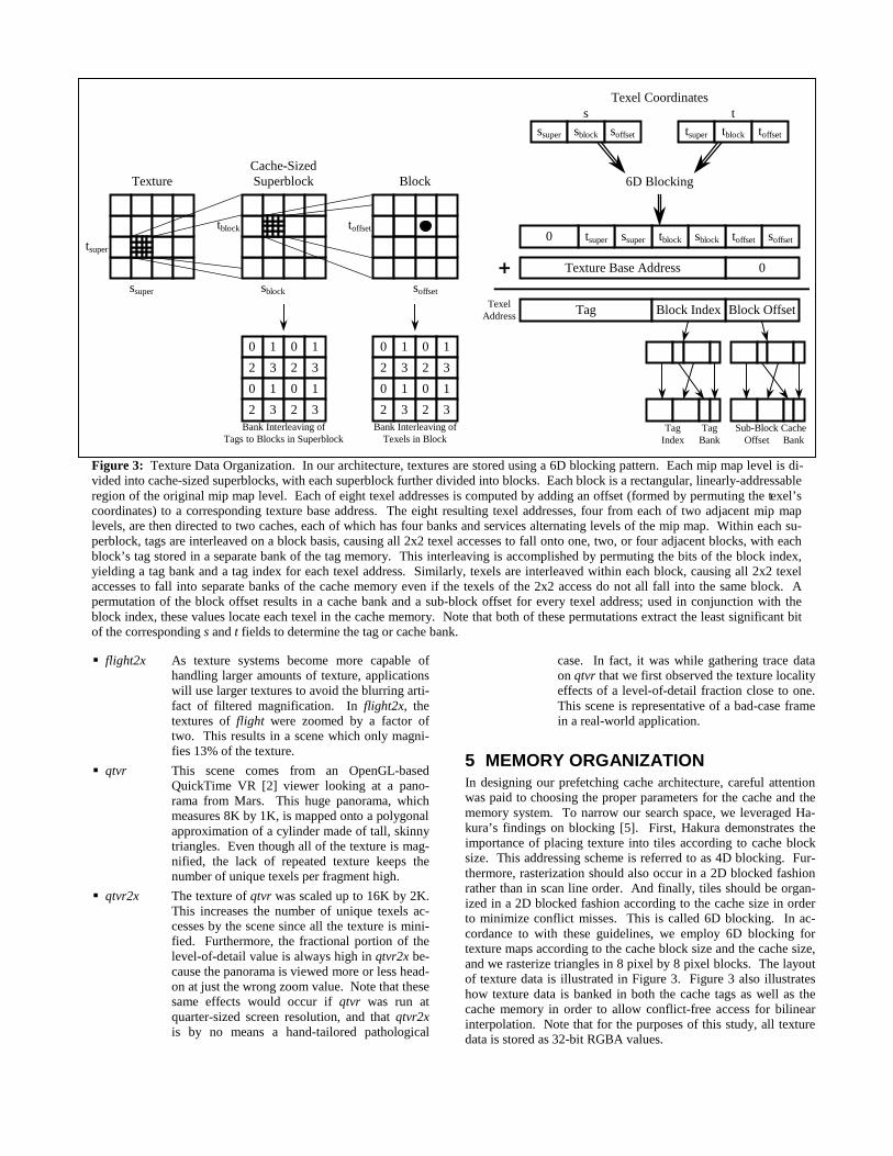
5 MEMORY ORGANIZATIONIn designing our prefetching cache architecture, careful attentionwas paid to choosing the proper parameters for the cache and thememory system. To narrow our search space, we leveraged Ha-kura’s findings on blocking [5]. First, Hakura demonstrates theimportance of placing texture into tiles according to cache blocksize. This addressing scheme is referred to as 4D blocking. Fur-thermore, rasterization should also occur in a 2D blocked fashionrather than in scan line order. And finally, tiles should be organ-ized in a 2D blocked fashion according to the cache size in orderto minimize conflict misses. This is called 6D blocking. In ac-cordance to with these guidelines, we employ 6D blocking fortexture maps according to the cache block size and the cache size,and we rasterize triangles in 8 pixel by 8 pixel blocks. The layoutof texture data is illustrated in Figure 3. Figure 3 also illustrateshow texture data is banked in both the cache tags as well as thecache memory in order to allow conflict-free access for bilinearinterpolation. Note that for the purposes of this study, all texturedata is stored as 32-bit RGBA values.
TexelAddress
TextureCache-SizedSuperblock Block
toffset
soffsetsblock
tsuper
ssuper
tblocksoffsettoffsetsblocktblockssupertsuper0
0Texture Base Address
Block OffsetTag Block Index
ssuper sblock soffset tsuper tblock toffset
TagIndex
Sub-BlockOffset
TagBank
CacheBank
Bank Interleaving ofTags to Blocks in Superblock
s t
0 1
2 3
0 1
2 3
0 1
2 3
0 1
2 3
0 1
2 3
0 1
2 3
0 1
2 3
0 1
2 3Bank Interleaving of
Texels in Block
6D Blocking
Texel Coordinates
Figure 3: Texture Data Organization. In our architecture, textures are stored using a 6D blocking pattern. Each mip map level is di-vided into cache-sized superblocks, with each superblock further divided into blocks. Each block is a rectangular, linearly-addressableregion of the original mip map level. Each of eight texel addresses is computed by adding an offset (formed by permuting the texel’scoordinates) to a corresponding texture base address. The eight resulting texel addresses, four from each of two adjacent mip maplevels, are then directed to two caches, each of which has four banks and services alternating levels of the mip map. Within each su-perblock, tags are interleaved on a block basis, causing all 2x2 texel accesses to fall onto one, two, or four adjacent blocks, with eachblock’s tag stored in a separate bank of the tag memory. This interleaving is accomplished by permuting the bits of the block index,yielding a tag bank and a tag index for each texel address. Similarly, texels are interleaved within each block, causing all 2x2 texelaccesses to fall into separate banks of the cache memory even if the texels of the 2x2 access do not all fall into the same block. Apermutation of the block offset results in a cache bank and a sub-block offset for every texel address; used in conjunction with theblock index, these values locate each texel in the cache memory. Note that both of these permutations extract the least significant bitof the corresponding s and t fields to determine the tag or cache bank.
5.1 Cache EfficiencySince we have decided to provide a separate cache for each of thebilinear accesses which needs to occur during every trilinear tex-ture access, three cache parameters need to be chosen. The firstchoice is the cache block size. A small block size increases missrates, but keeps bandwidth requirements low. A large block sizecan decrease miss rates, but bandwidth requirements and latencycan skyrocket. An additional factor that needs consideration isthat modern DRAM devices require large transfer sizes to sustainbandwidth. Hakura found that 16 texel tiles (64 bytes) work well,and most next-generation DRAM chips can achieve peak effi-ciency at such transfer sizes [4].
Given a 16 texel block size, we are left with choices for cacheassociativity and cache size. Figure 4 shows the miss rates for our
six test scenes. We see that increasing associativity does not de-crease the miss rate significantly. Intuitively, this make sensesince having a separate cache for alternate levels of a mip mapminimizes conflict misses. Thus, a direct-mapped cache is quiteacceptable if we use 6D blocking when alternate levels of the mipmap are cached independently. According to Hakura, if a unifiedcache is used for trilinear accesses (and thus the bilinear accessesdo not occur simultaneously), a 2-way set associative cache isappropriate. In the more general case of multi-texturing, m inde-pendent n-way set associative caches are well suited towards pro-viding texture accesses at the rate of m bilinear accesses per cycleto m*n textures (in this scheme, trilinear accesses count as twoaccesses to two textures). Since we are limiting our study to asingle trilinear access per cycle, two independent direct-mappedcaches are appropriate.
1 2 4 8 16 32 64 128
total cache size [KB]
0.0
0.1
0.2
0.3
0.4
mis
ses
per
frag
men
t
quake
0
2
4
6
texe
ls p
er f
ragm
ent
1 2 4 8 16 32 64 128
total cache size [KB]
0.0
0.1
0.2
0.3
0.4
mis
ses
per
frag
men
t
flight
0
2
4
6
texe
ls p
er f
ragm
ent
1 2 4 8 16 32 64 128
total cache size [KB]
0.0
0.1
0.2
0.3
0.4
mis
ses
per
frag
men
t
qtvr
0
2
4
6
texe
ls p
er f
ragm
ent
quakequake2x
flightflight2x
qtvrqtvr2x
1-way2-way4-way
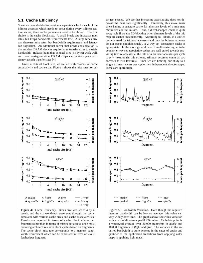
Figure 4: Cache Efficiency. Block size was set to 4 by 4texels, and the six workloads were sent through the cachesimulator with various cache sizes and cache associativities.Results are reported in terms of cache block misses perfragment rather than in terms of misses per access since mosttexturing architectures have clock cycles based on fragments.The cache block miss rate corresponds to a memory band-width requirement which can be expressed in terms of texelsfetched per fragment.
1 2 4 8 16 32 64 128
total cache size [KB]
0.0
0.1
0.2
0.3
0.4
mis
ses
per
frag
men
t
fragment0.0
0.1
0.2
0.3
0.4
mis
ses
per
frag
men
t
quake
0
2
4
6
texe
ls p
er f
ragm
ent
1 2 4 8 16 32 64 128
total cache size [KB]
0.0
0.1
0.2
0.3
0.4
mis
ses
per
frag
men
t
fragment0.0
0.1
0.2
0.3
0.4
mis
ses
per
frag
men
t
flight
0
2
4
6
texe
ls p
er f
ragm
ent
1 2 4 8 16 32 64 128
total cache size [KB]
0.0
0.1
0.2
0.3
0.4
mis
ses
per
frag
men
t
fragment0.0
0.1
0.2
0.3
0.4
mis
ses
per
frag
men
t
qtvr
0
2
4
6
texe
ls p
er f
ragm
ent
quakequake2x
flightflight2x
qtvrqtvr2x
Figure 5: Bandwidth Variation. Even though the requiredmemory bandwidth can be low on average, this value canvary widely over time. The graphs above show this variationwith a pair of direct-mapped 8 KB caches. Each data point isa windowed average over 30,000 fragments in quake and10,000 fragments in flight and qtvr. The variance in the re-quired bandwidth is quite extreme in the cases of quake andquake2x as the application transitions from applying colormaps to applying light maps.

Figure 4 also illustrates the effects of modifying the total cachesize on the miss rates of the various scenes. We see that forscenes in which texture locality is not dependent on repeated tex-tures (flight, flight2x, qtvr, qtvr2x), the miss rate curves flattensomewhere between a total cache size of 4 KB and 16 KB. Thiscache size represents the working set for filtering locality whenrasteriztion is done in 8 by 8 blocks. On scenes that contain re-peated texture (such as quake and quake2x) the miss rates arelower, but the miss rate curves flatten later (at 32 KB and 128 KB,respectively). These points correspond to the working set sizes ofthe repeated textures in each scene. The miss rate realized onceany of the curves flattens corresponds closely to the unique texelto fragment ratio of the respective scene.
We chose to use a 16 KB cache (composed of two direct-mapped 8 KB caches) for our study. According to our workloads,this size is large enough to exploit nearly all of the coherencefound in scenes which demonstrate poor locality (such as flight2xand qtvr2x), and even though a larger size could help in sceneswith repeated textures (such as quake and quake2x), these scenesalready perform very well. This cache size is in consensus withthe cache sizes proposed in other texture cache analyses [3, 5].Though we stress that different choices can also be reasonable, forthe rest of the paper, we assume a cache architecture with twodirect-mapped 8 KB caches (interleaved by mip map level) with64-byte blocks.
5.2 Bandwidth RequirementsIn formulating bandwidth requirements, we can relate the numberof texels of memory bandwidth required per fragment to the cachemiss rate by the cache block size. These equivalent measures areshown as left- and right-axes in Figure 4. One key point of Table1 and Figure 4 is that even though caching can work well some-times, there are cases when the bandwidth requirements are ex-tremely high. In the case of qtvr2x, nearly 3 texels have to befetched for each fragment no matter what size on-chip cache isutilized. This is quite high considering that eight texels are re-quired to texture a trilinearly mip mapped fragment. However,this should not be seen as an argument for not having a cache: thecache still provides a way of matching the access patterns of mipmapping with the large block requests required for achieving highmemory bandwidth. If a system wants to provide high perform-ance robustly over a wide variety of scenes, it needs to providehigh memory bandwidth even with the use of caching. If a sys-tem’s target applications have high texture locality, or if cost is aprimary concern, a memory system with lower memory band-width can be employed.
Figure 4 can also be a bit misleading because the averagebandwidth requirement does not tell the whole story. From thedata, one could falsely infer that a memory system which providesenough bandwidth to supply 1 texel per fragment will performperfectly on quake2x since, according to the graph, only 0.63texels per fragment are required given the 16 KB cache size.Figure 5 illustrates why this is not the case. The average cachemiss rate does not properly encapsulate temporal variations inbandwidth requirements. Even though the average bandwidthrequirement is 0.63 texels per fragment over the whole frame,large amounts of time exist when the system needs double thatbandwidth, and large amounts of time exist when the system doesnot need most of that bandwidth (i.e., when light maps are drawn).Because of the large separation in time between these two phases,a system cannot borrow from one to provide for the other, andthus the overall performance will decrease.
5.3 Memory ModelsIn order to validate our texture prefetching architecture more pre-cisely, we now explore the bandwidths and latencies provided bymemory systems. For our study, we examine an architecturewhich can sustain the texturing performance projected for the nearfuture. Current high-end architectures such as the SGI InfiniteRe-ality [9] provide approximately 200 million trilinear fragments persecond from a single board. Low-end professional-level archi-tectures provide approximately 30 million trilinear fragments persecond [7], as do many consumer-level graphics accelerators.Given these rates, we decided to set our nominal fragment clockrate at 200 MHz, meaning that under optimal memory conditions,the architecture provides a trilinearly sampled fragment every 5nanoseconds. Based on this fragment clock rate, we decided tosimulate four memory models, summarized by bandwidth andlatency histogram in Table 2.
� agp This models a system in which the texture cacherequests blocks from system memory over In-tel’s Advanced Graphics Port [6]. The AGP 4Xstandard can provide a sustained bandwidth of800 MB/sec. Because system memory is sharedwith the host computer, we estimate that the la-tency of agp varies between 250 nsec and 500nsec.
� rdram Direct RDRAM from Rambus [4] will serve asour baseline dedicated texture memory. Thesedevices provide extremely high bandwidth (asustainable 1.6 GB/sec) with reasonable latency(90 nsec) at high densities for commodity prices.We estimate that on-chip buffering logic adds 10nsec of latency to this memory.
� rdram2x In order to sustain the high and variable band-width requirements of scenes such of flight2xand qtvr2x, a texture architecture may choose toutilize 2 RDRAM parts for double the band-width of rdram at the same latency.
� numa Although not based on any existing specifica-tion, we use the numa memory model to exam-ine the feasibility of our prefetching architecturein novel and exotic texture memory architec-tures. The bandwidth of this memory model isthe same as the bandwidth of rdram2x, but thelatency of such a system is extremely high andhighly variable. It can range anywhere between250 nsec and 1.25 usec. This latency is in therange of what can be expected if texture is dis-tributed across the shared memory of a NUMAmultiprocessor [8].
agp rdram rdram2x numaperiod 16 8 4 4
latency
50 100 20 20 50 150 250
Table 2: Memory Models. The values reported here are interms of a fragment clock cycle of 200 MHz, which corre-sponds to 5 nsec. The memory period determines the rate atwhich 64 byte blocks of memory can be provided. Thus,bandwidths of 1, 2, 4, and 4 texels per fragment are providedon agp, rdram, rdram2x, and numa, respectively.
6 PERFORMANCE ANALYSISA cycle-accurate simulator was written to validate the robustnessof the prefetching texture cache architecture proposed in this pa-per. We analyze the architecture by running each scene with eachmemory model. First, the architecture is compared against anideal architecture and an architecture with no prefetching. Wethen account for all of our execution time beyond the ideal execu-tion time.
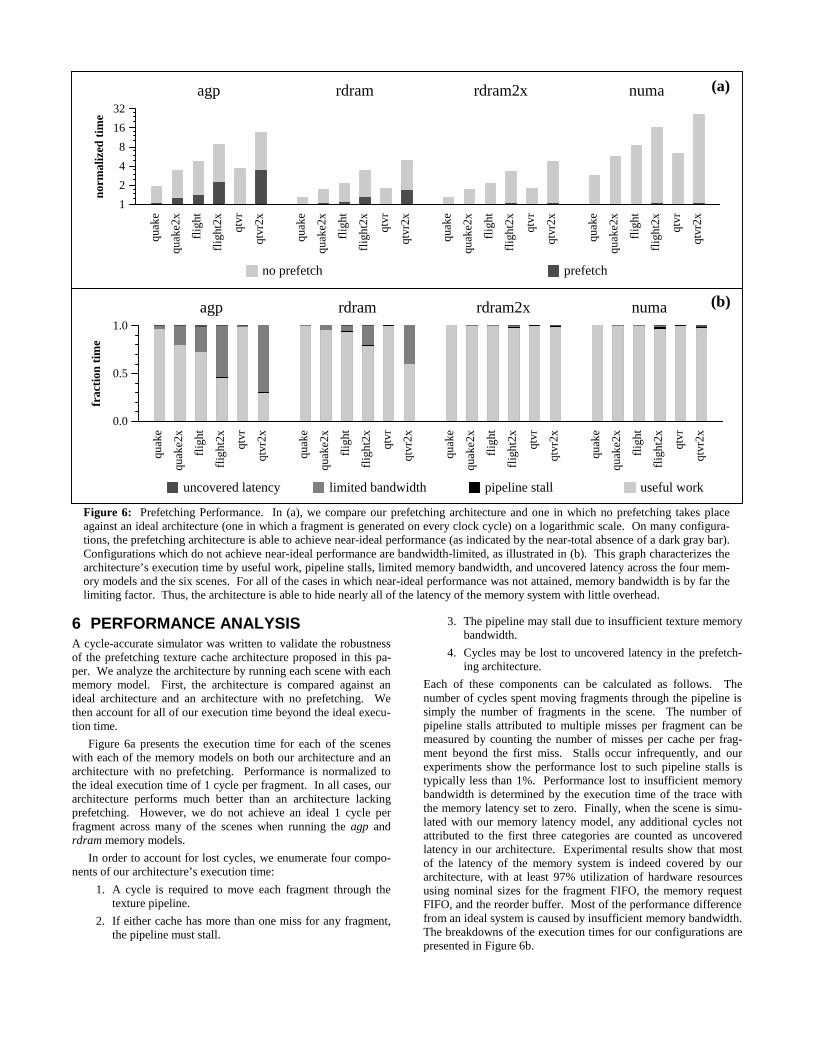
Figure 6a presents the execution time for each of the sceneswith each of the memory models on both our architecture and anarchitecture with no prefetching. Performance is normalized tothe ideal execution time of 1 cycle per fragment. In all cases, ourarchitecture performs much better than an architecture lackingprefetching. However, we do not achieve an ideal 1 cycle perfragment across many of the scenes when running the agp andrdram memory models.
In order to account for lost cycles, we enumerate four compo-nents of our architecture’s execution time:
1. A cycle is required to move each fragment through thetexture pipeline.
2. If either cache has more than one miss for any fragment,the pipeline must stall.
3. The pipeline may stall due to insufficient texture memorybandwidth.
4. Cycles may be lost to uncovered latency in the prefetch-ing architecture.
Each of these components can be calculated as follows. Thenumber of cycles spent moving fragments through the pipeline issimply the number of fragments in the scene. The number ofpipeline stalls attributed to multiple misses per fragment can bemeasured by counting the number of misses per cache per frag-ment beyond the first miss. Stalls occur infrequently, and ourexperiments show the performance lost to such pipeline stalls istypically less than 1%. Performance lost to insufficient memorybandwidth is determined by the execution time of the trace withthe memory latency set to zero. Finally, when the scene is simu-lated with our memory latency model, any additional cycles notattributed to the first three categories are counted as uncoveredlatency in our architecture. Experimental results show that mostof the latency of the memory system is indeed covered by ourarchitecture, with at least 97% utilization of hardware resourcesusing nominal sizes for the fragment FIFO, the memory requestFIFO, and the reorder buffer. Most of the performance differencefrom an ideal system is caused by insufficient memory bandwidth.The breakdowns of the execution times for our configurations arepresented in Figure 6b.
1
2
4
8
16
32no
rmal
ized
tim
eagp rdram rdram2x numa
quak
e
quak
e2x
flig
ht
flig
ht2x
qtvr
qtvr
2x
quak
e
quak
e2x
flig
ht
flig
ht2x
qtvr
qtvr
2x
quak
e
quak
e2x
flig
ht
flig
ht2x
qtvr
qtvr
2x
quak
e
quak
e2x
flig
ht
flig
ht2x
qtvr
qtvr
2x
no prefetch prefetch
agp rdram rdram2x numa
0.0
0.5
1.0
frac
tion
tim
e
quak
e
quak
e2x
flig
ht
flig
ht2x
qtvr
qtvr
2x
quak
e
quak
e2x
flig
ht
flig
ht2x
qtvr
qtvr
2x
quak
e
quak
e2x
flig
ht
flig
ht2x
qtvr
qtvr
2x
quak
e
quak
e2x
flig
ht
flig
ht2x
qtvr
qtvr
2x
uncovered latency limited bandwidth pipeline stall useful work
Figure 6: Prefetching Performance. In (a), we compare our prefetching architecture and one in which no prefetching takes placeagainst an ideal architecture (one in which a fragment is generated on every clock cycle) on a logarithmic scale. On many configura-tions, the prefetching architecture is able to achieve near-ideal performance (as indicated by the near-total absence of a dark gray bar).Configurations which do not achieve near-ideal performance are bandwidth-limited, as illustrated in (b). This graph characterizes thearchitecture’s execution time by useful work, pipeline stalls, limited memory bandwidth, and uncovered latency across the four mem-ory models and the six scenes. For all of the cases in which near-ideal performance was not attained, memory bandwidth is by far thelimiting factor. Thus, the architecture is able to hide nearly all of the latency of the memory system with little overhead.
(a)
(b)
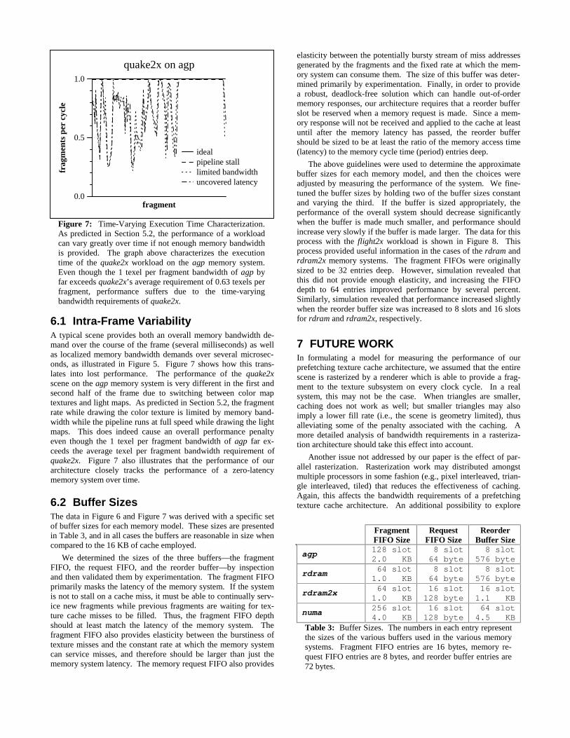
6.1 Intra-Frame VariabilityA typical scene provides both an overall memory bandwidth de-mand over the course of the frame (several milliseconds) as wellas localized memory bandwidth demands over several microsec-onds, as illustrated in Figure 5. Figure 7 shows how this trans-lates into lost performance. The performance of the quake2xscene on the agp memory system is very different in the first andsecond half of the frame due to switching between color maptextures and light maps. As predicted in Section 5.2, the fragmentrate while drawing the color texture is limited by memory band-width while the pipeline runs at full speed while drawing the lightmaps. This does indeed cause an overall performance penaltyeven though the 1 texel per fragment bandwidth of agp far ex-ceeds the average texel per fragment bandwidth requirement ofquake2x. Figure 7 also illustrates that the performance of ourarchitecture closely tracks the performance of a zero-latencymemory system over time.
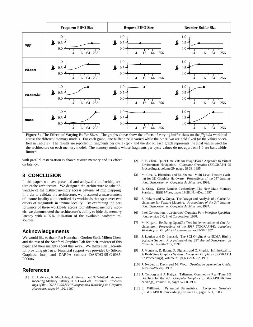
6.2 Buffer SizesThe data in Figure 6 and Figure 7 was derived with a specific setof buffer sizes for each memory model. These sizes are presentedin Table 3, and in all cases the buffers are reasonable in size whencompared to the 16 KB of cache employed.
We determined the sizes of the three buffers—the fragmentFIFO, the request FIFO, and the reorder buffer—by inspectionand then validated them by experimentation. The fragment FIFOprimarily masks the latency of the memory system. If the systemis not to stall on a cache miss, it must be able to continually serv-ice new fragments while previous fragments are waiting for tex-ture cache misses to be filled. Thus, the fragment FIFO depthshould at least match the latency of the memory system. Thefragment FIFO also provides elasticity between the burstiness oftexture misses and the constant rate at which the memory systemcan service misses, and therefore should be larger than just thememory system latency. The memory request FIFO also provides
elasticity between the potentially bursty stream of miss addressesgenerated by the fragments and the fixed rate at which the mem-ory system can consume them. The size of this buffer was deter-mined primarily by experimentation. Finally, in order to providea robust, deadlock-free solution which can handle out-of-ordermemory responses, our architecture requires that a reorder bufferslot be reserved when a memory request is made. Since a mem-ory response will not be received and applied to the cache at leastuntil after the memory latency has passed, the reorder buffershould be sized to be at least the ratio of the memory access time(latency) to the memory cycle time (period) entries deep.
The above guidelines were used to determine the approximatebuffer sizes for each memory model, and then the choices wereadjusted by measuring the performance of the system. We fine-tuned the buffer sizes by holding two of the buffer sizes constantand varying the third. If the buffer is sized appropriately, theperformance of the overall system should decrease significantlywhen the buffer is made much smaller, and performance shouldincrease very slowly if the buffer is made larger. The data for thisprocess with the flight2x workload is shown in Figure 8. Thisprocess provided useful information in the cases of the rdram andrdram2x memory systems. The fragment FIFOs were originallysized to be 32 entries deep. However, simulation revealed thatthis did not provide enough elasticity, and increasing the FIFOdepth to 64 entries improved performance by several percent.Similarly, simulation revealed that performance increased slightlywhen the reorder buffer size was increased to 8 slots and 16 slotsfor rdram and rdram2x, respectively.
7 FUTURE WORKIn formulating a model for measuring the performance of ourprefetching texture cache architecture, we assumed that the entirescene is rasterized by a renderer which is able to provide a frag-ment to the texture subsystem on every clock cycle. In a realsystem, this may not be the case. When triangles are smaller,caching does not work as well; but smaller triangles may alsoimply a lower fill rate (i.e., the scene is geometry limited), thusalleviating some of the penalty associated with the caching. Amore detailed analysis of bandwidth requirements in a rasteriza-tion architecture should take this effect into account.
Another issue not addressed by our paper is the effect of par-allel rasterization. Rasterization work may distributed amongstmultiple processors in some fashion (e.g., pixel interleaved, trian-gle interleaved, tiled) that reduces the effectiveness of caching.Again, this affects the bandwidth requirements of a prefetchingtexture cache architecture. An additional possibility to explore
FragmentFIFO Size
RequestFIFO Size
ReorderBuffer Size
agp 128 slot2.0 KB
8 slot 64 byte
8 slot576 byte
rdram 64 slot1.0 KB
8 slot 64 byte
8 slot576 byte
rdram2x 64 slot1.0 KB
16 slot128 byte
16 slot1.1 KB
numa 256 slot4.0 KB
16 slot128 byte
64 slot4.5 KB
Table 3: Buffer Sizes. The numbers in each entry representthe sizes of the various buffers used in the various memorysystems. Fragment FIFO entries are 16 bytes, memory re-quest FIFO entries are 8 bytes, and reorder buffer entries are72 bytes.
fragment0.0
0.5
1.0
frag
men
ts p
er c
ycle
quake2x on agp
idealpipeline stalllimited bandwidthuncovered latency
Figure 7: Time-Varying Execution Time Characterization.As predicted in Section 5.2, the performance of a workloadcan vary greatly over time if not enough memory bandwidthis provided. The graph above characterizes the executiontime of the quake2x workload on the agp memory system.Even though the 1 texel per fragment bandwidth of agp byfar exceeds quake2x’s average requirement of 0.63 texels perfragment, performance suffers due to the time-varyingbandwidth requirements of quake2x.
with parallel rasterization is shared texture memory and its effecton latency.
8 CONCLUSIONIn this paper, we have presented and analyzed a prefetching tex-ture cache architecture. We designed the architecture to take ad-vantage of the distinct memory access patterns of mip mapping.In order to validate the architecture, we presented a measurementof texture locality and identified six workloads that span over twoorders of magnitude in texture locality. By examining the per-formance of these workloads across four different memory mod-els, we demonstrated the architecture’s ability to hide the memorylatency with a 97% utilization of the available hardware re-sources.
AcknowledgementsWe would like to thank Pat Hanrahan, Gordon Stoll, Milton Chen,and the rest of the Stanford Graphics Lab for their reviews of thispaper and their insights about this work. We thank Phil Lacroutefor providing glstrace. Financial support was provided by SiliconGraphics, Intel, and DARPA contract DABT63-95-C-0085-P00006.
References[1] B. Anderson, R. MacAulay, A. Stewart, and T. Whitted. Accom-
modating Memory Latency In A Low-Cost Rasterizer. Proceed-ings of the 1997 SIGGRAPH/Eurographics Workshop on GraphicsHardware, pages 97-102, 1997.
[2] S. E. Chen. QuickTime VR: An Image-Based Approach to VirtualEnvironment Navigation. Computer Graphics (SIGGRAPH 95Proceedings), volume 29, pages 29-38, 1995.
[3] M. Cox, N. Bhandari, and M. Shantz. Multi-Level Texture Cach-ing for 3D Graphics Hardware. Proceedings of the 25th Interna-tional Symposium on Computer Architecture, 1998.
[4] R. Crisp. Direct Rambus Technology: The New Main MemoryStandard. IEEE Micro, pages 18-28, Nov/Dec. 1997.
[5] Z. Hakura and A. Gupta. The Design and Analysis of a Cache Ar-chitecture for Texture Mapping. Proceedings of the 24th Interna-tional Symposium on Computer Architecture, 1997.
[6] Intel Corporation. Accelerated Graphics Port Interface Specifica-tion, revision 2.0, Intel Corporation, 1998.
[7] M. Kilgard. Realizing OpenGL: Two Implementations of One Ar-chitecture. Proceedings of the 1997 SIGGRAPH/EurographicsWorkshop on Graphics Hardware, pages 45-56, 1997.
[8] J. Laudon and D. Lenoski. The SGI Origin: A ccNUMA HighlyScalable Server. Proceedings of the 24th Annual Symposium onComputer Architecture, 1997.
[9] J. Montrym, D. Baum, D. Dignam, and C. Migdal. InfiniteReality:A Real-Time Graphics System. Computer Graphics (SIGGRAPH97 Proceedings), volume 31, pages 293-302, 1997.
[10] J. Neider, T. Davis and M. Woo. OpenGL Programming Guide.Addison-Wesley, 1993.
[11] J. Torborg and J. Kajiya. Talisman: Commodity Real-Time 3DGraphics for the PC. Computer Graphics (SIGGRAPH 96 Pro-ceedings), volume 30, pages 57-68, 1996.
[12] L. Williams. Pyramidal Parametrics. Computer Graphics(SIGGRAPH 83 Proceedings), volume 17, pages 1-11, 1983.
Fragment FIFO Size Request FIFO Size Reorder Buffer Size
agp
1 4 16 64 2560.0
0.5
1.0
fpc
1 4 16 64 2560.0
0.5
1.0
fpc
4 16 64 2560.0
0.5
1.0
fpc
rdram
1 4 16 64 2560.0
0.5
1.0
fpc
1 4 16 64 2560.0
0.5
1.0
fpc
4 16 64 2560.0
0.5
1.0
fpc
rdram2x
1 4 16 64 2560.0
0.5
1.0
fpc
1 4 16 64 2560.0
0.5
1.0
fpc
4 16 64 2560.0
0.5
1.0
fpc
numa
1 4 16 64 2560.0
0.5
1.0
fpc
1 4 16 64 2560.0
0.5
1.0fp
c
4 16 64 2560.0
0.5
1.0
fpc
Figure 8: The Effects of Varying Buffer Sizes. The graphs above show the effects of varying buffer sizes on the flight2x workloadacross the different memory models. For each graph, one buffer size is varied while the other two are held fixed (at the values speci-fied in Table 3). The results are reported in fragments per cycle (fpc), and the dot on each graph represents the final values used forthe architecture on each memory model. The memory models whose fragments per cycle values do not approach 1.0 are bandwidth-limited.
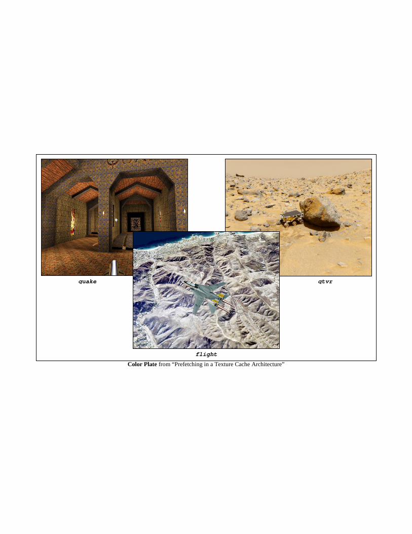
Color Plate from “Prefetching in a Texture Cache Architecture”
quake qtvr
flight