prediction of lifting surface flutter at - icas 887 ashley et al.pdf · prediction of lifting...
TRANSCRIPT

PREDICTION OF LIFTING SURFACE FLUTTER AT SUPERSONIC SPEEDSt
By H. ASHLEY*,W.J. MYKYTOW**, J. R. MARTUCCELLI***
Summary — Accumulated evidence indicates that, for many low-aspect-ratio lifting sur-faces and for mission profiles typical of many present-day aircraft, flutter may be aserious design problem at supersonic as well as at transonic speeds. Following a dis-cussion of the effects of aerodynamic heating, measured flutter speeds and frequenciesarc presented for a related series of uniform, cantilevered rectangular wings at Machnumbers between 1.5 and 5.0. The remainder of the paper is devoted to various attemptsat rational theoretical prediction of the experimentally determined eigenvalues. It isfound that a two-degree-of-freedom representation based on free vibration modesof a uniform beam-rod is suitable for establishing equations of motion, but that theaerodynamic derivatives must be properly chosen for each particular speed range.One significant conclusion is that basic supersonic flutter theory has now received thesame degree of confirmation that has long existed for straight wings of large span inincompressible flow.
SYMBOLS
a Ambient speed of sound in airReference semichord of lifting surface (constant for the
rectangular wings analyzed below)c = zb Chordlength of lifting surfaceh, Amplitude of (positive downward) bending oscillation of
elastic axis at wingtip
Mass moment of inertia in pitch about elastic axis, perunit span, at reference station on lifting surface
(JG)REF Torsional rigidity at reference chordwise cross section of lifting surface
1. This research was supported by the United States Air Force under Contract No.AF 33 (616)-5690.
The authors are indebted to Messrs. Lowell Andrew and Richard Lassen ofMissile Division, North American Aviation, Inc., for extensive cooperation on the three-dimensional aerodynamic calculations.
* Professor, Aeronautics and Astronautics, Massachusetts Institute of Technology.** Chief, Dynamics Branch, Flight Dynamics Laboratory, Wright Air Development
Division, U.S. Air Force.*** Senior Research Engineer, Aeroelastic and Structures Research Laboratory,
Massachusetts Institute of Technology.
[8871

888 H. ASHLEY, W. J. MYKYTOW and J. R. MARTUCCELLI
rn Mass per unit spanwise distance at reference station onlifting surface
M = Vla Flight Mach numberq=!,p1/2 Flight dynamic pressure
17„ = IOEIntb2 Radius-of-gyration parameterMaximum thickness of airfoil section at reference station
on lifting surfaceV Flight speed or test-section flow speed in wind tunnel
Lowest speed for neutral dynamic aeroelastic stability(flutter) of lifting surface
Piston velocitya, Amplitude of (positive leading-edge upward) torsional
oscillation of wingtipRatio of specific heats in air
=4pb2
Mass ratio
Ambient density in air00 Phase angle by which wingtip bending oscillation leads
torsional oscillationCircular frequency of simple harmonic motion
Wf Circular frequency for neutral dynamic aeroelastic stability(flutter) of lifting surface
IVh Frequency of fundamental mode of coupled bending vi-bration of wing
w, Frequency of fundamental mode of coupled torsional vi-bration of wing
WhEffective frequencies of uncoupled modes, calculated as
e'
described under Presentation of Data0(...) Identifies a quantity of the same or smaller order of mag-
nitude than (...)
INTRODUCTION
IT is not difficult in the year 1960 to make a strong case for the need ofaccurate theory capable of predicting lifting surface flutter throughoutthe supersonic flight regime. Up to approximately 1945 the structuralrigidity required to meet strength or static load criteria was generallymorethan adequate to prevent dynamic aeroelastic instability on fixed wingsand tails (although the same could not be said about the trailing-edgecontrols and tabs of that era). But subsequent progress in aerodynamicsand propulsion, coupled with the reduced thickness ratios permitted byimproved materials and techniques of structural analysis, produced

Prediction of Lifting Surface Flutter at Supersonic Speeds ' 889
a steady increase in the ratio of flight dynamic pressure to stiffness to thepoint where satisfactory strength no longer assured freedom from flutter.Flutter prevention therefore became an important design considera-tion; new criteria and procedures were necessary.
The requisite information has gradually been supplied from a com-bination of analytical and experimental research. For transonic speeds,emphasis had to be placed on the reduced-scale model approach. A suit-able theory was lacking at the same time that this range was recognized
4.0
tincreasing Dynamic Pressure
__ Constant Dynamic Pressure3.0
DecreasingAltitude '41)Ç
2.0
q. / IncreasingAltitude
3.0
.0 ••• ••
D.
UnstableRegion
45°
K1.5 °
60°I1.0
//
/4"-->......Constant—Altitude/Flight Lines
Stable Region
0 0.5 1.0 1.5 2.0 2.5
Mach Number
FIG. I. Experimentally determined flutter stability boundaries, on a plot of dimensionless velocity index Vf/bwOEI/tz vs. Mach number, for cantilever model wings of three different planforms. Constant altitude flight is represented by a
straight line through the origin. (Adapted from Garrickw.)
as being critical from the standpoint of flight safety. Model tests, sup-plemented by semi-empirical analyses, ultimately supplied the data toestablish the flutter boundaries, the margins of safety, the changes fre-quently needed to prevent instability and, in some cases, the optimumaircraft design from considerations of flutter. Extensive investigationshad to be conducted on certain transonic configurations, such as fixedsurfaces of very low thickness ratio, T-tails, mass-unbalanced controlsurfaces, wings with external stores and all-movable controls.

890 H. ASHLEY, W. J. MYKYTOW and J. R. MARTUCCELLI
To illustrate current trends, the stability boundaries of Fig. 1 havebeen adapted from Garrick"). These curves are typical of what can beconstructed from the large quantities of data now available near andaboN, e Mach number unity (e.g. Lauten and Burgess(2)). They show, forinstance, that the particular swept wing chosen here is critical at transonicspeeds; if no flutter occurs up to M 1, it can proceed safely far intothe supersonic range, even at constant altitude.
Throughout the present paper we use the velocity index Vf/bwo I ,u asa measure of the tendency to flutter. The changes in this index nearM = 1 can be attributed to the variations in lift-curve slope and aero-dynamic center as a wing accelerates from subsonic to supersonic flight.The rapid rise of the velocity index or the supersonic alleviation is notso great, however, as originally expected from zero thickness, linearizedaerodynamic theory. The unconservatism of linear theory, which waspointed out by Ashley and Zartarian(3), results primarily from a forwardshift of aerodynamic center due to profile shape and thickness. In Fig.1, the stability boundaries for the two delta wings tend toward constantvalues of velocity index at the higher M, this tendency being more pro-nounced for the higher leading-edge sweep. It can be speculated .thatthis behaviour results from the smaller variation of aerodynamic para-meters with M as the aspect ratio is decreased. In any event, the imme-diate transonic region is not necessarily the most dangerous for the deltas.Thus, the relationship between the constant-altitude line and the boundaryfor the 45°-planform indicates a critical range extending roughly fromM = 1 to 1.5. If this wing is designed to fly at appreciably greater q super-sonically than transonically, the first encounter with flutter may bedistinctly supersonic. The same can be said for the 60°-delta, which dis-plays an even wider range of M where instability could be met.
Although the foregoing examples are not all-inclusive, the data dosuggest that the supersonic regime may be a critical one for many low-aspect-ratio surfaces. This statement is substantiated by the observationthat dangerous high-q regions at low altitudes may be avoided throughdeliberately specified or accepted speed placards. Clearly the means mustbe at hand for preventing flutter at supersonic speeds and, possibly forsome unique designs, at hypersonic speeds.
Flutter models may be employed to determine stability informationfor specific configurations on a direct-analog basis, to develop trend dataof the sort presented in Fig. 1, or to assist in establishing and improvingthe accuracy of procedures for theoretical prediction. It was with thelatter two objectives in mind that the measurements discussed in thispaper were carried out. These were conducted by the Aeroelastic andStructures Research Laboratory, M.I.T., at the request of Wright Air
Prediction of Lifting Surface Flutter at Supersonic Speeds 891
Development Division, USAF, (1) to provide systematic data on a seriesof similar models in the range of 1.5 M 5.0, and (2) evaluate theaccuracy of the supersonic analytical prediction technique known as "pis-ton theory". This was a scheme adapted by M.I.T. investigators fromearlier theoretical formulations of Hayes") and Lighthillo>. Such infor-mation is required at a sufficiently early date to advance the "state ofthe art" and to underwrite the design of advanced flight vehicles.
AEROTHERMOELASTIC EFFECTS
Before the experimental results are set down and compared with theirpredicted counterparts, a few words are in order about the influence ofaerodynamic heating on supersonic flutter. At, high speeds the destabi-lizing effects of steady-state and transient heating on rigidities will re-quire consideration not only because of their influences on frequenciesbut also on frequency ratios. Garrick(1) describes results of a NACAhot jet experiment on a solid bending-torsion model. This model flutteredfor a short interval primarily on account of loss in rigidity due to tran-sient thermal stresses and the associated changes in frequency ratios andfrequencies. It was entirely stable, however, when injected into a similarcold jet (see also Runyan and Jones(6)).
The potential impact of aerodynamic heating on dynamic and staticaeroelasticity was early recognized and stimulated extensive research.References (7,8,9) are a small sample of U.S. documents reportingresults of investigations. Dryden and Duberg (9) describe an interestingand complicated aerothermoelastic phenomenon involving significantamounts of chordwise deformations. This "flag-waving flutter" occurredduring hot jet tests on a multiweb wing. Chordwise deformations willvery likely require much more attention in future designs.
At the present time, the general procedure .in aeroelasticity is to sep-arate the aerothermoelastic problem into two phases—the aerothermalproblem and the aeroelastic one. Bisplinghoff and Dugundji(m) showthat such a procedure implies two assumptions, which are (1) small coup-ling between heat transfer and elastic deformation, and (2) small couplingbetween static and dynamic aerothermoelastic effects. However, theseM.I.T. investigators also point out that dynamic coupling between aero-thermal and aeroelastic aspects is unlikely, since thermal transient char-acteristic times are generally long when compared to periods of struc-tural vibration important to flutter.
Many investigators have proved that exact aerothermoelastic simu-lation is not feasible except for a 1:1 model or replica. It should benoted that, because of aerodynamic heating effects on moduli and

892 H. ASHLEY, W. J. MYKYTOW and J. R. MARTUCCELLI
changes in rigidities due to thermal stresses, the determination of theexperimental time scale must consider both aircraft and model histories.That is, aerothermoelastic phenomena are a function of aircraft flightpath and maneuvers. While the rocket-model approach may appear togive more realistic combinations of dynamic pressure and temperaturethan the "non-heated" wind tunnel, the additional rocket propulsionand aerodynamic performance similarity parameters required from flightpath considerations or the altitude-speed limit boundary may not permitcomplete aerothermoelastic simulation. Nevertheless, the rocket-modeltechnique does present a means for obtaining high temperatures andhigh dynamic pressures. Use of this experimental tool will likely be ex-panded to obtain data for developing and improving both experimentaland analytical approaches in resolving flight vehicle aerothermoelasticproblems. Moreover, limitations on available stagnation temperaturerender the continuous wind-tunnel even more deficient in this respect.
Calligeros and Dugundji1111 evaluate similarity requirements up to1000°F or about M = 3.5. They point out that the primary conflictis between the Mach number, Reynolds number and pressure-structuralmodulus ratio conditions. Of lesser importance are conflicts of charac-teristic time, radiation and Frounde number effects. They also observethat exact similitude is possible only for a 1 :1 scale ratio. Three possibleapproaches are discussed by the authors in detail:
to use different materials and test media (gas) for the model;
to investigate special conditions by considering plate-like behavior;a nd
to relax one of the major conflicting requirements.
In the latter case, the Reynolds number condition is shown to be aredefinition of the time scale. (See also Garricku) for a similar discussionon time sequence dissimilarity.)
In view of the similitude conflicts briefly mentioned above, it will benecessary to employ restricted-purpose models and, in many cases, toseparate the aerothermal and aeroelastic phases of the problem. Never-theless, as in the past, these models will be indispensable for investigatingspecial aspects of the various phases of the aerothermoelastic problemarea. Obviously such test results can be employed to provide data forthe development of theoretical approaches and to evaluate and improvethe accuracy of analytical prediction methods. In some cases, the modelmay be used as an approximate analog of the full-scale vehicle. For the"quasi-steady thermodynamic approach", the effective stiffnesses, in-cluding increases or reductions due to thermal stress, are estimated fromanalyses and possibly test data and are specified as functions of time.

Prediction of Lifting Surface Flutter at Supersonic Speeds 893
A series of models is then constructed and tested to evaluate the morecritical "time-frozen" conditions.
Considerable research is required to develop and to validate similarityprocedures in aerothermoelasticity,especially with reference to relaxationof conflicting similarity requirements. Rocket model tests will providesignificant information on combined high heating and aerodynamicpressure effects. However, here again conflicts in similarity will likelyrequire tests with different geometric scale ratios. It is probable that exactor nearly exact simulation by ground facilities and reduced scale modelswill not be possible. Thus, an accurate validation of the various step-by-step phases of the separation technique will be required. The final modeltests might involve some limited combined environmental tests eitherin a heated wind tunnel or by means of rockets. A decrease in the extentof exact similarity will of course emphasize the importance and the needfor the flight flutter test. Here again the question of the influence of flightpath must be evaluated. In addition to the effort needed in the area ofaerothermoelastic similitude requirements, considerable research anddevelopment are needed in connection with the design, construction andtesting of both static and dynamic aerothermoelastic models.
The above-mentioned effects of airplane flight path or history on fluttercharacteristics have been investigated by California Institute of Techno-logy for specific cases under United States Air Force Contract AF33(616)-5767. The results, reported by Harder et a1."2), cover analyticalstudies of a hypothetical straight wing in the speed-altitude region M = 3at sea level to M = 5 at 50,000feet. One analog computation concerneda long flight at M = 5 and 50,000feet followed by a reduction in speedto M = 1.5,an M = 1.5dive to sea level, and an acceleration to M = 3.0.This maneuver was sufficient to lose a considerable "cold-wing" marginof safety. Flutter of the hypothetical wing resulted at sea level as M = 3.0was reached. The loss in torsional rigidity was due to a reduction in elasticmoduli caused by "hot soak" at high altitude and to detrimental thermal-stress effects from the low-altitude acceleration to M = 3.0. The influenceof vibration amplitude on effective rigidities and flutter stability was notinvestigated.
The research discussed in the following sections concerns tests in anunheated tunnel and thus no aerothermal effects are included.
PRESENTATION OF DATA
Very little experimental information on flutter at distinctly supersonicspeeds is to be found in the literature, particularly for M = 3 and above.An im portant exception is the NACA Research Memorandum by Runyan
894 H. ASHLEY, W. J. MYKYTOW and J. R. MARTUCCELLI
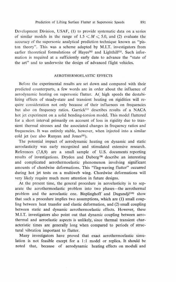
and Morgan113>, which shows a reasonable agreement between pistonstrip-theory calculations and measured stability-boundary locations atM = 3 and 7 for I l%,-thick double-wedge and 4%-thick truncated-double-wedge wing models. Although these correlations for these limited
,
c 1 z
4
Vf
butoe4T.Unstable
Region StableRegion
0 I 2 3 4 5 6
(at
ae
0 I 2 3 4 5 6
Mach Number
FIG. 2. Values of lif/bw,e1 /—zand Wf/tva, vs. Mach number measured on canti-
lever, half-span models of square planform and 4-%-thick, truncated double-
wedge profile shape. Other model parameters typical of current practice.
cases suggest optimism regarding the theory, extended research involvingsystematic variations of Mach number and other wing properties stillappears to be desirable.
Figures 2-4 summarize the result of the test program, which wasdesigned to supply such systematic information regarding the effects
Prediction of Lifting Surface Flutter at Supersonic Speeds 895
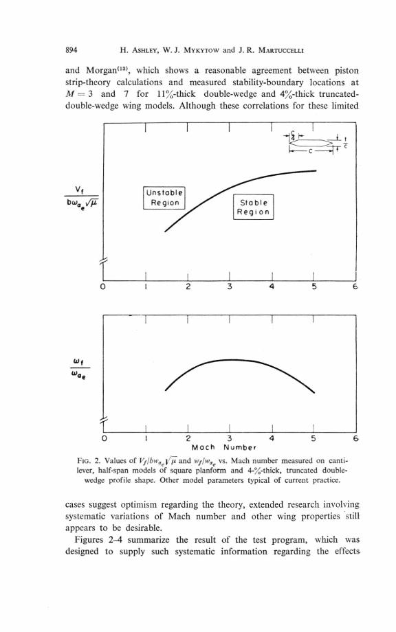
of the parameters M, thickness ratio, t/c, and aspect ratio. The otherdimensionless characteristics of model wings were held constant as nearlyas possible, and are typical of current practice. Further details are reportedby Martuccelli114).
Vf
bcoae
Unstable Region
StableRegion
\0.03 0.04 0.05 0.06 0.07 0.08 0.09
Cdf
Wae
003 0.04 0 05 0.06 0.07 0 08 0 09
Thickness Ratio ()
FIG. 3. Values of VflbwŒelip—and wf/w„, vs. thickness ratio t/c measured on
cantilever, half-span models of square planform and truncated double-wedge
profile shape at M = 3.0. Other model parameters typical of current practice.
The type of model construction employed was the metal spar balsa-wood profile arrangement used in other flutter research programs carriedout at M.I.T."5). The technique is inexpensive and yields structures whichdisplay clearly defined beam-rod elastic characteristics and tend to flutterin the cantilever, first bending-first torsion mode. The balsa gives the
896 H. ASHLEY, W. J. MYKYTOW and J. R. M 4RTUCCELLI
desired aerodynamic shape, and airloads are transmitted by it to an alu-minum spar, whose thickness and width can be varied to control theflexural and torsional rigidities of the model and whose chordwise locationfixes the elastic axis. Lead weights are distributed fore and aft of the spar
Unstable Region
Vf
bcaceVTF.StableRegion
0 1.0 2.0 3.0 4.0 5.0
U.P1
0 1.0 2.0 3.0 4.0 50Full - Span Aspect Ratio
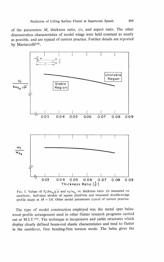
FIG. 4. Values of Vf/bw -VWand wf/rvŒe vs. full-span aspect ratio measured on rectangular, cantilever, half-span models with 4%-thick, truncated double-
wedge profile shape at M = 3.0. Other model parameters typical of currentpractice.
in such a way as to give the desired mass, mass unbalance, and radiusof gyration. Model instrumentation consists of two strain-gage bridges,which supply information on bending and torsional strains at the root.The gages are suitable for quantitative measurement of frequency and
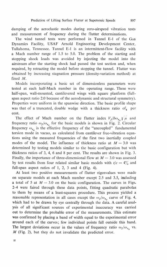
Prediction of Lifting Surface Flutter at Supersonic Speeds 897
damping of the aeroelastic modes during zero-airspeed vibration testsand measurement of frequency during the flutter determinations.
The wind tunnel tests were performed in Tunnel E-1 of the GasDynamics Facility, USAF Arnold Engineering Development Center,Tullahoma, Tennessee. Tunnel E-1 is an intermittent-flow facility w ith
a Mach number range of 1.5 to 5.0. The problem of the starting andstopping shock loads was avoided by injecting the model into theairstream after the starting shock had passed the test section and, whenrequired, by retracting the model before stopping the tunnel. Flutter wasobtained by increasing stagnation pressure (density-variation method) atfixed M.
Models incorporating a basic set of dimensionless parameters weretested at each half-Mach number in the operating range. These werehalf-span, wall-mounted, cantile‘ered wings with square planform (full-span aspect ratio 2.0 because of the aerodynamic and structural symmetry).Properties were uniform in the spanwise direction. The basic profile shapewas that of a truncated, double wedge with a thickness ratio of, percent.
The effect of Mach number on the flutter index Vf/boo ,u andfrequency ratio cof/wŒ, for the basic models is shown in Fig. 2. Circularfrequency coe is the effective frequency of the "uncoupled" fundamentaltorsion mode in vacuo, as calculated from cantilever free-vibration equa-tions using the measured frequencies of the first two inertially coupledmodes of the model. The influence of thickness ratio at M = 3.0 wasdetermined by testing models similar to the basic configuration but withthickness ratios of 3, 4, 6 and 8 per cent. The results are shown in Fig. 3.Finally, the importance of three-dimensional flow at M = 3.0 was assessedby test results from four related similar basic models with t/c = 4% andfull-span aspect ratios of 1, 2, 3 and 4 (Fig. 4).
At least two positive measurements of flutter eigenvalues were madeon separate models at each Mach number except 2.5 and 3.5, includinga total of 5 at M = 3.0 on the basic configuration. The curves in Figs.2-4 were faired through these data points, fitting quadratic parabolasto them by means of a least-squares procedure. This process yielded areasonable representation in all cases except the (01/04,,, curve of Fig. 4,
which had to be drawn by eye centrally through the data. A careful anal-ysis of all significant sources of experimental inaccuracy was carriedout to determine the probable error of the measurements. This estimatewas confirmed by placing a band of width equal to the experimental erroraround each of the curves; few individual points fall outside this band.The largest deviations occur in the values of frequency ratio cof/coxe vs.M (Fig. 2), but they do not invalidate the predicted error.
57

898 H. ASHLEY, W. J. MYKYTOW and J.R. MARTUCCELLI
COMPARISON BETWEEN THEORY AND EXPERIMENT
Assuming for the moment that the system has two degrees of freedom,one in bending and one in torsion, a dimensional analysis of the complexeigenvalue problem leads to the following conclusion: the dimensionlessflutter speed VflbwŒe and frequency ratio of/roŒe for lifting surface withfixed planform geometry and affine profile shapes are functions of massratio p, structural frequency ratio o)„,/w„e, Mach number M, thicknessratio t/c, radius-of-gyration parameter FOE, and the dimensionless chord-wise locations of the elastic axis and center of gravity. This listing omitsthe influence of structural friction, which was very small for all modelsand, on theoretical grounds, would cause no more than a 1 per cent changein any measured speed or frequency. The last three qualities in the fore-going list were held within extremely close tolerances throughout theprogram. M and tic were varied in a prescribed fashion. A word mustbe said, however, regarding the more significant variations in p andwhe/o)„, from one test to another.
Owing to the fact that ambient density in the wind tunnel becomesprogressively lower as M is raised, the mass ratio p at flutter increasedby a factor exceeding 2 between the low and high ends of the speed scale.Since this behavior seems unavoidable in any such experiments, it isfortunate that a large amount of theoretical and experimental evidencehas been accumulated (e.g. Ashley and Zartarian") which shows, fora variety of wings and modes of instability in the ranges of aeronauticalinterest, that 171 is almost exactly proportional to j p. That is, ifVflbw,rej ,u is employed to describe stability boundaries, the mass ratiocan be dropped from the enumeration of parameters above. On a similarbasis, (of turns out to be essentially independent of tr.
As for the frequency ratio ro, fro2e, the exigencies of model construc-tion caused it to deviate up to 307/. from the nominal value desired, thehigher ratios being associated with the lower Mach numbers. In the cal-culations to be presented, the mean (Oh/W OEfoi all models tested at eachM was inserted into the flutter equations corresponding to that M.Inasmuch as the eigenvalues are not particularly sensitive to moderatevariations in this parameter about its nominal value, it is believed thatthis difficulty has negligible effect on the soundness of the conclusionsreached below.
No effort is made here to reproduce details of flutter computationprocedures or unsteady aerodynamic theory, these subjects being wellcovered in the literature to be cited. As a first, rather elementary attemptat correlation with the data in Figs. 2-4, the characteristic determinantwas constructed by the Rayleigh—Ritz method, using generalized coordi-

Prediction of Lifting Surface Flutter at Supersonic Speeds 899
nates associated w,ith the fundamental, uncoupled modes of flexural andtorsional vibration of a uniform cantilever (cf. Eqs. (9-89) and (9-90)
oft")). Running lift and pitching moment were taken from second-orderpiston theory"), without adjustment for induction or wingtip losses buttakinz account of the actual profile shape and thickness. The neutrallystable solutions are plotted in Figs. 5 through 7. Curves obtained by
Vf
bui 47. a e
Unstable Region
//
#.--- -Zero Thickness
True Thickness
StobleRegion
Experiment
Piston-Strip Theory
0 I 2 3 4 5
True Thickness
......malZ•1•10.=1•••••
f s.
coo
0 I 2 3 4 5
Moch Number
Flo. 5. Data of Fig. 2 compared with stability boundaries calculated using two uncoupled modes of a uniform, cantilever beam-rod and aerodynamic co-
efficients from second-order piston theory.
57*

900 H. ASHLEY, W. J. MYKYTOW and J. R. MARTUCCELLI
setting t/c = 0 have been added to the velocity index plots of Figs. 5 and 7. The serious unconservatism of the zero-thickness predictions confirms the we1l-known(3) destabilizing influence of the forward shift in aerody-
UnstableRegion
v f
b w ael.F.••••• .,
Stable Region
Experiment
Piston-StripTheory
0.03 0.04 0.05 0.06 0.07 0.08
EI.Vf
• ••• 4MIIM • •
— 7)0.03 0.04 0.05 0.06 0.07 0.08
Thickness Ratio (tic)
FIG. 6. Data of Fig. 3 compared with stability boundaries calculated usingtwo uncoupled modes of a uniform cantilever beam-rod and aerodynamic co-
efficients from second-order piston theory.
namic center proportional to the parameter Mt/c. For straight wingsof the general type represented here, the conclusion seems inescapablethat wholly-linearized aerodynamic derivatives are unsatisfactory forestimating supersonic aeroelastic stability.

Prediction of Lifting Surface Flutter at Supersonic Speeds 901
Despite a tendency to be slightly unconservative, piston theory predictsthe location of the stability boundary of Fig. 5 to within the probableexperimental error for M „>-- 3. The same is not true of the calculatedfrequencies, although the apparent discrepancies between the cof/w„.
UnstableRegion
— —
Zero Thickness
Vf
bcoae-Vii
True Thickness
Stable
Region
Experiment
--- Piston-StripTheory
0 1.0 2.0 3.0 4.0
True Thickness
0 10 2.0 3.0 4.0
Full- Span Aspect Ratio
Fig. 7. Data of Fig. 3 compared with stability boundaries calculated using two uncoupled modes of a uniform cantilever beam-rod and aerodynamic co-
efficients from second-order piston theory.

902 H. ASHLEY, W. J. MYKYTOW and J. R. MARTUCCELLI
curves are magnified by a scale expansion which is roughly twice thatof the velocity-index scale. As might be expected, the greatest frequencydeviation is observed at the lowest M, where the validity of the theoryis seriously questionable.
It is a matter of common experience among aeroelasticians that fre-quency coj is predicted less accurately by a given theory than speed I71.An even more sensitive index—but one that is rarely available—is theflutter mode shape. During the present program, high-speed motionpictures were taken of each test with the camera pointed very nearly alongthe elastic axis. It w as afterward discovered that rough measurementsof the bending and torsional amplitudes at the wingtip, and of the phaseangle 00 by which the bending oscillation (positive downw ard) leadsthe torsion (positive leading-edge up), could be extracted from the films.In the table which follows, a representative sample is given of measuredand predicted values of 0, and amplitude ratio hdko . The experimentalerrors for these two quantities are estimated at + 100 and + 20%,respectively. Nevertheless, the comparisons leave something to be desired,especially at the higher M. It would seem that more use should be madeof careful determinations and correlations of experimental and analyticalmode shape data for a critical evaluation of flutter theories.
TABLE 1
Representative inode-shape data
Experimental Theoretical
11/ha 0 'to holbao q „
1.5 1.51 27° 1.55 13.9°2.0 1.28 13° 1.70 11.7'3.0 1.59 14° 1.24 9.0°4.0 1.50 9° 0.92 5.9°5.0 I 1.77 30° 0.92 4.1°
In view of the reasonably satisfactory agreement on speed and frequencyat M = 3.0 achieved for the basic model configuration, it is not surprisingthat Fig. 6 displays correctly estimated trends of these two quantitieswith varying thickness ratio. Regarding Fig. 7, the theoretical curvesare horizontal straight lines because none of the dimensionless systemparameters is changed when strip-type derivatives are employed andthe aspect ratio is varied in such a way as to keep Wheko„, constant. Inactuality, the only significant influence of span comes about throughthe changing fraction of the total plan area that senses the presence of
Prediction of Lifting Surface Flutter at Supersonic Speeds 903
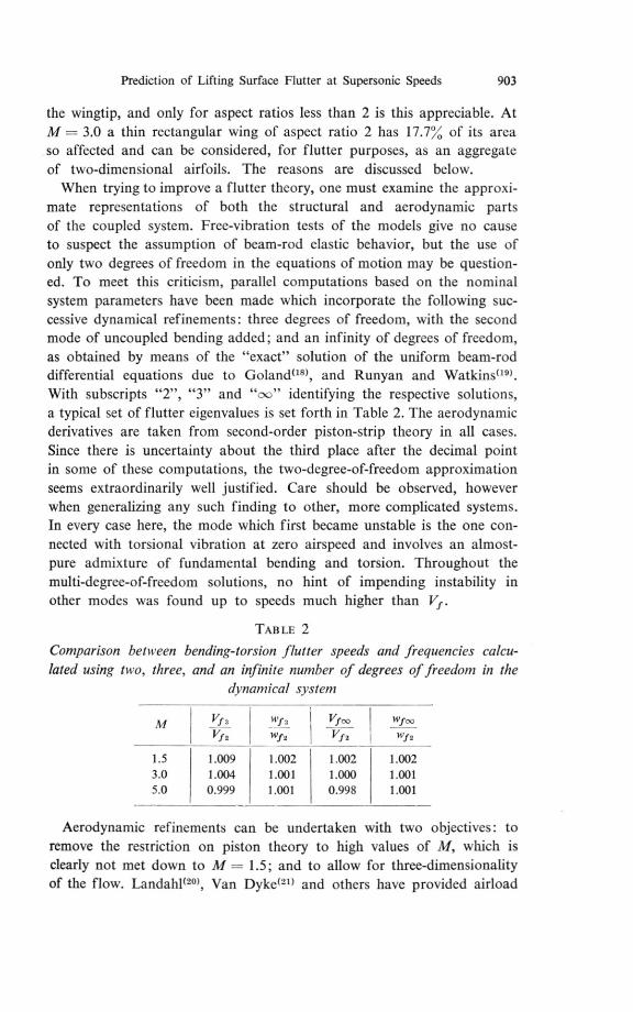
the wingtip, and only for aspect ratios less than 2 is this appreciable. AtM = 3.0 a thin rectangular wing of aspect ratio 2 has 17.7% of its areaso affected and can be considered, for flutter purposes, as an aggregateof two-dimensional airfoils. The reasons are discussed below.
When trying to improve a flutter theory, one must examine the approxi-mate representations of both the structural and aerodynamic partsof the coupled system. Free-vibration tests of the models give no causeto suspect the assumption of beam-rod elastic behavior, but the use ofonly two degrees of freedom in the equations of motion may be question-ed. To meet this criticism, parallel computations based on the nominalsystem parameters have been made which incorporate the following suc-cessive dynamical refinements: three degrees of freedom, with the secondmode of uncoupled bending added; and an infinity of degrees of freedom,as obtained by means of the "exact" solution of the uniform beam-roddifferential equations due to Goland", and Runyan and Watkins(19).With subscripts "2", "3" and "Dc)" identifying the respective solutions,a typical set of flutter eigenvalues is set forth in Table 2. The aerodynamicderivatives are taken from second-order piston-strip theory in all cases.Since there is uncertainty about the third place after the decimal pointin some of these computations, the two-dcgree-of-freedom approximationseems extraordinarily well justified. Care should be observed, howeverwhen generalizing any such finding to other, more complicated systems.In every case here, the mode which first became unstable is the one con-nected with torsional vibration at zero airspeed and involves an almost-pure admixture of fundamental bending and torsion. Throughout themulti-degree-of-freedom solutions, no hint of impending instability inother modes was found up to speeds much higher than 1/j. .
TAB LE 2
Comparison between bending-torsion flutter speeds and frequencies calcu-
lated using two, three, and an infinite number of degrees of freedom in the dynamical system
Vf, wf2 w12Vf2
1/100V f2 W12
1.5 1.009 1.002 1.002 1.0023.0 1.004 1.001 1.000 1.0015.0 0.999 1.001 0.998 1.001
Aerodynamic refinements can be undertaken with two objectives: toremove the restriction on piston theory to high values of M, w hich isclearly not met down to M = 1.5; and to allow for three-dimensionalityof the flow. Landahl(20', Van Dyke(") and others have provided airload

904 1-1. ASHLEY, W. J. MYKYTOW and J. R. MARTUCCELLI
expressions for airfoils oscillating at lower supersonic Mach numbers while retaining the all-important ingredient of nonlinearity. The first of these theories is somewhat easier to apply, and the results of intro-
UnstableRegion
Piston—Strip Theory
Stable Region
Piston—Strip Theory, With Landahl Correction
— Experiment--- Theory
0 2 3 4 5 6
Piston—Strip Theory
cot .••••
a Piston—Strip TheoryWith Landahl Correction
0 I 2 3 4 5 6
Mach Number
FIG. 8. Data of Fig. 2 compared with stability boundaries calculated by three-
degree-of-freedom analysis using aerodynamic coefficients from second-order piston theory, with and without the correction terms from Landahloo.
ducing it into the modal flutter calculations are presented in Fig. 8. Lan-dahl criticizes second-order piston theory on the grounds that it includeseffects 0(0/0) while neglecting those which are 0(t/cM3), thus implyingthat t/c > 11M3. For the 4%-thick profiles used in the present investiga-

Prediction of Lifting Surface Flutter at Supersonic Speeds 905
tions, this would strictly call for M >4, at least. The Landahl formula-tionoo expands the velocity potential, pressure coefficient, etc., in increasingpowers of t/c and l/M2. His objections are quite well met by retaining
only the piston terms plus those 0(t/cM3), and this is what has been done.The improved velocity-index curve of Fig. 8 can now be said to fall
within experimental error when M 2. Once again, the agreement onflutter frequency is less satisfactory. It is, nevertheless, much more uniformthroughout the Mach-number range.
To combine thickness effects with three-dimensional flow in an entirelyrational manner is not yet within the state of the art. Yet there is apossibility, when the eigenvalues are not excessively sensitive to thethickness parameter (cf. Fig. 6), of adjusting linearized theory on a semi-empirical basis. For instance, one may take the distributions of oscil-latory pressure loading computed by means of supersonic aerodynamicinfluence coefficients (32'23) and supplement them by the term
W,y( ,,+1) mazt/dx — prior to integrating the generalized forces used
in the flutter equations. The quantity d.7,/dx represents the local chord-wise slope of the semi-thickness distribution of the wing, and the termitself is easily deduced from piston theory. Alternatively and less rigor-ously, one can developed flutter curves from linearized computations, thenadjust the ordinates by the ratio between corresponding curves obtainedby two dimensional aerodynamics with and without the thickness effect.
The three-dimensional calculations without thickness, as expected,yield a very unconservative prediction of flutter speed, the variationwith Mach number being not substantially different from the upper dashedcurve on Fig. 5. After a rough thickness adjustment of the latter typediscussed above, results are found which closely agree with the Landahlcurve on Fig. 8 but which are no nearer than it is to the measured speeds.This lack of improvement at the lower end of the Mach number is dueto the fortuitous accuracy of the two-dimensional estimates, and three-dimensional theory should certainly be used in other, more complicatedcases. The success of the Landahl method at M = 1.5 and 2 can be attrib-uted here to the mutual cancellation of two errors of opposite sign. Onthe one hand, the oscillatory loads drop off to zero as the wingtip is ap-proached, but, on the other, what loads are present become more effectivein producing flexure-torsion instability by virtue of the forward displace-ments of the sectional aerodynamic centers in the tip region.
CONCLUSIONS
For many classes of lifting surface and for mission profiles typical ofthe operation of many modern aircraft types, flutter may be a serious
906 II. AsimEy, W. J. MYKYTOW and J. R. M kRTUCCELLI
design problem at supersonic as well as at transonic speeds. The paraboli-cally shaped curve of critical velocity I/J-vs. Mach number in the super-sonic regime, suggested for several years by theoretical studies on simplewings, appears to be well justified by the experimental evidence.
With regard to rational methods of flutter prediction in the generalrange 1.5 < M < 5.0, it seems fair to conclude that they have now receivedthe same sort of confirmation that was provided for the theory of sub-sonic, bending-torsion flutter of straight wings by a series of investigationsin the late 1930's (24,25)are good examples from the British and Americanliterature). As with all such statements concerning aeroelastic stability,this conclusion is a tentative one, based on tests with a single structuralconfiguration in which several of the many important parameters hadfixed values throughout. It must be emphasized that cases can be con-structed where the eigenvalues are extremely sensitive to a certain para-meter and where no theory can ever be successful. Such is the situationon an unswept wing when the frequency ratio Ivh/W„is small and thechordwise positions of center of gravity and aerodynamic center are closetogether.
In setting up flutter calculations, proper regard must be had both forthe structural complexity and for the suitable choice of aerodynamicderivatives. Experience at lower flight speeds can serve as a guide in thefirst instance. On lifting surfaces of the general shape and aspect ratiodealt with here, what is acceptable aerodynamically depends on the Machnumber. Unadjusted, second-order piston theory appears valid betweenabout M = 3, and M = 5, and possibly to an upper limit fixed by thesize of Mt/c, where entropy changes and other distinctly hypersonic pheno-mena prevent accurate prediction of the pressure distribution by pistontheory. Proceeding downward from M = 3, a two-dimensional adjust-ment such as those proposed by Landahl(20) and Van Dyke(") must firstbe introduced. Finally, there will be Mach numbers above the transonicrange where only three-dimensional airloads, adjusted semi-empiricallyfor thickness effect, can yield satisfactory predictions for the purposesof final design.
REFERENCES
GARRICK, I. E., Some Concepts and Problem Areas in Aircraft Flutter, Instituteof the Aeronautical Sciences, S.M.F. Fund Paper No. FF-15, March 1957.LAUTEN, W. T., Jr. and BURGESS, M. F., Flutter Investigation in the High Subsonic
and Transonic Speed Range on Cantilever Delta-Wing Plan Forms with Leading-
Edge Sweepback of 60°, 53°8' and 45°, NACA Research Memorandum L56K26,January 1957.

Prediction of Lifting Surface Flutter at Supersonic Speeds 907
ASHLEY, H. and ZARTARIAN,G., Piston Theory—A New Aerodynamic Toolfor the Aeroelastician, Jour. Aero. Sci. 23, No. 12, December 1956, pp. 1109-1118.
HAYES, W. D., On Hypersonic Similitude, Quarterly of Applied Mathematics, 5,No. 1, April 1947, pp. 105-106.LIGHTILL,M. J., Oscillating airfoils at High Mach Number, Jour. Aero. Sci. 20,No. 6, June 1953, pp. 402-406.
RUNYAN, H. L. and JONES, N. H., Effect of Aerodynamic Heating on the Flutterof a Rectangular Wing at a Mach Number of 2, NACA Research MemorandumL58C31, June 1958.
BISPLINGHOFF,R. L., Some Structural and Aeroelastic Considerations of HighSpeed Flight, the Nineteenth Wright Brothers' Lecture, Jour. Aero. Sci. 23, No. 4,April 1956, pp. 289-321.
S. BUDIANSKY,B. and MAYERS, J., Influence of Aerodynamic Heating on the Effec-tive Torsional Stiffness of Thin Wings, Jour. Aero. Sci. 23, No. 12, December 1956,pp. 1081-1093, 1108.
DRYDEN, H. L. and DUBERG, J. E., Aeroelastic Effects of Aerodynamic Heating,Fifth General Assembly of AGARD, Ottawa, June 1955.HOFF, N. J., Editor, High Temperature Effects in Aircraft Structures, BISPLINGHOFF,R. L. and DUGUNDJI, J., Influence of Aerodynamic Heating on Aeroelastic Phe-nomena, Chapter 15 of Agardograph 28, Pergamon Press. New York, 1958.
CALLIGEROS,J. M. and DUGUNDII, J., Similarity Laws Required for ExperimentalAerothermoelastic Studies, Aeroelastic and Structures Research'i Laboratory,Massachusetts Institute of Technology, Technical Report No. 75-1,' May 1959.Office of Naval Research, Department of the Navy:Contract No. Nonr-1841 (46).
HARDER, R. L., Locic, L., MCCANN, D. G., WILTS, D. W. and ROYCE, W. W.,Supersonic Flutter Analyses Including Aerodynamic Heating Effects, Wright AirDevelopment Division Technical Report 59-559, February 1960. (United StatesAir Force Contract AF 33 (616)-5767.)RUNYAN, H. L. and MORGAN, H. G., Flutter at Very High Speeds, NACA ResearchMemorandum L57D16a, June 1957.MARTUCCELLI,J. R., Flutter Model Tests at Mach Numbers 1.5-5.0, Wright AirDevelopment Center Technical Report 59-407, September 1959. (Report CONFI-DENTIAL, title UNCLASSIFIED.)MCCARTHY, J. F., Jr., ASHER, G. W., PRIGGE, J. S., Jr. and LEVEY, G. M., Three-Dimensional Supersonic Flutter Model Tests Near Mach Number 1.5, Part I.Model Design and Testing Techniques, Wright Air Development Center TechnicalReport 54-113, Part 1, December, 1955.ASHLEY, H. and ZARTARIAN,G., Supersonic Flutter Trends as Revealed by PistonTheory Calculations, Wright Air Development Center Technical Report 58-74,May 1958.
BISPLINGHOFF,R. L., ASHLEY, H. and HALFMAN,R. L., Aeroelasticity, Addison-Wesley Publis hing Company, Reading, Mass., 1955.GOLAND, M., The Flutter of a Uniform Cantilever Wing, Journal of AppliedMechanics, 12, No. 4, December 1945, pp. A-197-A-208.RUNYAN, H. L. and WATKINS, C. E., Flutter of a Uniform Wing with an ArbitrarilyPlaced Mass According to a Differential-Equation Analysis and a Comparisonwith Experiment, NACA Report 966, 1960.LANDAHL,M. T., Unsteady Flow Around Thin Wings at High Mach Numbers,Jour. Aero. Sci. 24, No. 1, January 1957, pp. 33-38.
908 H. ASHLEY, W. J. MYKYTOW and J. R. MARTUCCELLI
VAN DYKE, M. D., Supersonic Flow Past Oscillating Airfoils Including NonlinearThickness Effects, NACA Report 1183, 1954.PINES, S., DUGUNDH, J. and NEURINGER, J., Aerodynamic Flutter Derivatives fora Flexible Wing with Supersonic and Subsonic Edges, Jour. Aero. sa. 22, No. 10,October 1955, pp. 693-700.ZARTARIAN, G. and Hsu, P. T., Theoretical Studies on the Prediction of UnsteadySupersonic Airloads on Elastic Wings, Parts I and II, Wright Air DevelopmentCenter Technical Report 56-97, December 1955 and February 1956 (ReportCONFIDENTIAL, title UNCLASSIFIED.)DUNCAN, W. J. and LYON, H. M., Calculated Flexural-Torsional Flutter Character-istics of Some Typical Cantilever Wings, British A.R.C. Reports: and MemorandaNo. 1782, 1937.THEODORSHEN, T. and GARRICK, I. E., Mechanism of Flutter, A Theoretical andExperimental Investigation of the Flutter Problem, NACA Report 685, 1940.
DISCUSSION
H. LEE: I should like to ask whether the author has any information on the varia-tion of the suberitical darn7ing with speed. In particular, is there any information onthe comparison between theory and test?
In a case with which I am familiar, for an aeroplane flying at high subsonic speeds,there was a considerable discrepancy between the variation of damping with speedas determined by calculation, by wind-tunnel test and by flight test. In this case, thediscrepancy was in the dangerous way, the calculations showing a gradual reductionin damping with speed, the wind tunnel tests a moderately rapid reduction, and thefull-scale flight tests a very rapid reduction indeed; this resulted in the loss of an aero-
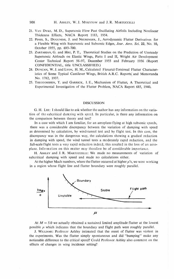
plane. Infw-mation on this matter may therefore be of considerable importance.ASHLEY and J. R. MARTUCCELLI: We made no measurements of variation of
suberitical damping with speed and made no calculations either.At the higher Mach numbers, where the flutter occurred at higher jes, we were working
in a region whose flight line and flutter boundary were roughly parallel.
Boundary
StableFlight path
Unstable
At M = 5.0 we actually obtained a sustained limited amplitude flutter at the lowestpossible it which indicates that the boundary and flight path were roughly parallel.
J. WILLIAMS: Professor Ashley intimated that the onset of flutter was violent inthe experiments. Was the flutter simply spontaneous and did "bumping" make anynoticeable difference to the critical speed? Could Professor Ashley also comment on theeffects of changes in wing incidence setting?
Prediction of Lifting Surface Flutter at Supersonic Speeds 909
H. ASHLEY and J. R. MARTUCCLLLI: Flutter was spontaneous in all cases.I presume that "bumping" means to give model a jolt so as to initiate flutter. Thiswe never found necessary.
We did make two runs where we approached the flutter boundary very slowly, soas to try and save the model after flutter began. We were able to do this and were ableto save the models. In both cases vve tested the models again under the same tunnelconditions, except that we made a normal time run and did not try to save model. Theresults for the "slow" and "fast" runs IA ere identical.
A. VAN DLR NEUT: The models used vvere flexible in bending and torsion andhad negligible deformation in chordwise sense. For actual low aspect ratio wings thisdeformation will be important. Would you expect, Dr. Ashley, that your conclusionwith the 2 degrees of freedom that available theory predicts flutter very well may beextended to the case in which the chordwise deflections have to be accounted for?
H. A SHLEY and J. R. MARTUCCELLI: No, as based on our observations, but otherresults suggest optimism on this point.
D. J. JOHNS: Regarding the subject of choice of modes, are the authors aware of anyexperimental evidence to suggest a coupling between the lifting surface modes of deforma-tion (i.e. torsion and bending) and chordwise bending modes of single (or more) wingskin panels. I am in fact suggesting that there may be a coupling between "classical"wing flut ter and panel flutter. Might not such a coupling explain the flutter observedin the NACA hot jet experiments reported in the paper?
H. ASHLEY and J. R. MARTUCCLI I I: None.