prediction of l1mit state behavior of reinforced masonry systems with nonllnear … · ·...
TRANSCRIPT
- 837 -
PREDICTION OF L1MIT STATE BEHAVIOR OF REINFORCED MASONRY SYSTEMS WITH NONLlNEAR ANAL YTICAL MODELS
F. Seible, Ph.D., P.E. Professor of StructuraJ Engineering Department of AMES University of California, San Diego La Jolla, CA 92093-0411 U.SA
ABSTRACT
G.R. Kingsley and A.G. Kürkchübasche Graduate Research Assistants Department of AMES University of California, San Diego La Jolla, CA 92093-0411 U.SA
In the design and analysis of reinforced masonry structures in seismic zones, it is important to be able to predict the complete behavior of structural systems through ali major design Iimit states, well beyond the linear elastic range. Furthermore, it is desirable that analytical models be capable of characterizing not only the behavior of individual structural components, but also their interaction in complete structural systems. A primary task of the U.S.-TCCMAR (Technical Coordinating Committee for Masonry Research) program is to develop analytical models, supported by extensive experimental verification, for the analysis of masonry structures from the materiais levei to full-scale component assemblages and complete structural systems. In this paper, recent progress in the development of nonlinear finite element based models wiIJ be discussed. The theoretical basis for the models will be summarized briefly. A detailed comparison of analytical predictions with experimental results form the TCCMAR program and related research is presented. Analyses and correlation studies are discussed for (1) a two-story perforated masonry shear wall with precast, prestressed floor slabs tested at the University of Texas, Austin, and for (2) a reinforced masonry beam-column joint, as well as (3) a flanged masonry wall or wall-to-wall intersection, both tested at the University of California, San Diego.
INTRODUCTION
Comprehensive analytical and experimental investigations are currently in progress under the umbrella of the U.S.-TCCMAR (Technical Coordinating Committee for Masonry Research) program to develop state-of-the-art design guidelines for masonry buildings in seismic zones. With a limited number of full-scale experiments, the primary objective of lhe experimental research effort is the verification and validation of phenomenological analytical models which can subsequently be employed to perform detailed parameter studies for design model development. Three leveis of analytical models with increasing complexity are being developed [1], namely (1) lumped parameter models which simulate seismic building response through mass-spring systems, (2) structural component models which capture structural systems behavior by modeling component assemblages with predefined member end force-deformation characteristics, and (3) finite element models which predict complex nonlinear systems behavior in a geometrically correct domain with realistic materiais input at the constitutive leveI.
At the most detailed levei of this analytical modeling effort, lhe finite element model is used to predict the complete nonlinear response of reinforced masonry systems under fully reversed cyclic loading to provide the necessary design model development information, and to define for the other analytical tasks appropriate component behavior input data. A brief overview of the finite element model development is presented in the following, together with a detailed demonstration of the model capabilities in terms of predicting and tracing the complete response of complex masonry subassemblages and systems subjected to simulated seismic loads.

- 838-
ANAL YTICAL MODEL OVERVIEW
The finite element model PCYCO, developed for the analysis of reinforced masonry systems, is based on higher order isoparametric overlaid elements in which the reinforcement and the fully grouted masonry are formulated separately and connected by compatibility requirements. The constitutive behavior of the grouted masonry is based on an orthogonally anisotropic material model with smeared and rotating crack theory. An equivalent uniaxial strain approach has been utilized with a material damage parameter [2] providing coupling between the principal directions for tension-compression stress states. Material induced anisotropy due to the orientation of the masonry mortar joints can be considered. Steel reinforcement may be characterized as smeared or discrete overlays in the horizontal and vertical direction and tension stiffening between cracks can be accounted for through masonry or reinforcement referred formulations.
The model allows for fully reversed cyclic loading for seismic load simulation based on fully grouted masonry and reinforcement constitutive relationships depicted in Fig. 1. A consistent envelope based principal plane updating procedure accounts for rotating principal directions during unloading and reloading cycles. A detailed description of the developed analytical model can be found in [3] and [4], together with verification examples comparing both monotonic and cyclic load histories with full-scale reinforced masonry component tests.
ANAL YTICAL MODEL APPLlCATIONS
The above outlined finite element model has been successfully applied to predict the complete nonlinear response and criticai design limit states such as first cracking , yielding and crushing of full-scale experiments on fully grouted reinlorced concrete masonry systems tested under the U.S.-TCCMAR programo Ali TCCMAR tests used 150 mm (6 in.) units. In addition to test predictions, the analytical program has contributed greatly to the understanding of reinforced masonry behavior through parameter variation and sensitivity studies performed in conjunction with experimental benchmark data. A demonstration 01 these applications is provided in the following.
a) Predjction of Perforated Sbear Wall Response
Two-story reinforced concrete shear walls were tested under the TCCMAR program by Klingner et alo [5] at the University of Texas, Austin. The two-story shear wall tests include coupled wall specimens and perforated walls with door and window openings. A true pre-test prediction of the behavior of a perforated wall test was made using the developed nonlinear finite element model. Predicted cracking, yielding and crushing patterns are shown in Figs. 2a and 2b. Figure 2a shows the cracking pattern at a lateral displacement of -5 mm, and Fig. 2b shows predicted locations of yielding steel (line segments) and crushing masonry (shaded) at a lateral displacement of -50 mm. The depicted distress pattems for two horizontal floor loads of equal magnitude to the left indicate that the wall will respond with hinging in the left column member and compression toe failure of the main wall next to the door opening. No yield penetration into the upper story was predicted. Subsequent test results confirmed these findings. The lateral load-deformation envelopes for this perforated wall are depicted in Fig. 2c for both analytical prediction and the experiment. Close agreement between prediction and test can be observed. The prediction also included assessment of critical design limit states such as first cracking, first yielding, and onset of crushing as iIIustrated in Fig. 2c.
b) Predjctjon of Beam-Column Jojnt Response
The application of the analytical model to a masonry frame structure is depicted in Fig . 3. A reinforced concrete masonry beam-column connection with joint shear

- 839-
------------------~~r-------~-,.--4~-----~m
A
I I
J I
I , I
I I
I I
I I
I I
(a) Grouted Masonry with Masonryreferred Tension Stiffening
I I
-f
(b) Reinforcernent
f 9 Modified sleel law following crackin of masonry
"
, , ,
fs
f m Masonry in tension
5% residual
~------------------~9 ~~============~~m ~a e~
(c) Steel-referred Tension Stiffening
Figure 1. Constitutive Relationships

z .!I:
"CJ d o
o-l
'-;;l ~ Q)
...> d
o-l
- 840-
5.08 m
f f-J-'~
-/
=~ / / -'-I-
~I-
f-~
I-f- /
2.64m I-r- I
1-1- ~
f-f-hp-: -, 1--' f-
I:' I'- rID " ~ r-r-
/ " ITr- / I , I / /
f-I- " / 2.64m / -- r- II:n f-t- :: :n: :1: 1 :J ~:= Ui :: :o :n :J
1-1-/ - -
nn / -r-r- /
/
:.llll - -r-p I - - -
/ /
llll - - -'-~ / - - '-'/'-
(a) Cracking Patterns (b) Yielding and Crushing
660
460
360
260
160
60
-60
-160
-260
-360
-460
-660 -60
(shaded) Patterns
-- Anolytical Prediction ..e--o ~ Experimental Envelope (Preliminary)
Loading lo the left (North):
• Firsl cracking 01 u= -0.25 mm • Firs t yield ing 01 u= -5.84 mm .... First crushing aI u= -17.5 mm
Laading to the r ight (South):
• Firsl cracking at u= 0. 154 mm • Firs! yielding 01 u= 6.86 mm .... Firs! crushing 01 u= 15.7 mm
-40 -30 -20 -10 O 10 20 30 40 Lateral Displacement (mm)
(c) Lateral Load vs. Displacement Response
Figure 2. Prediction of 2-Story Perforated Shear Wall Response
60

300
250
-z .=- 200 "C t'Il o
...J 150 -t'Il M Q) ., t'Il 100 ...J
50
O 0.0
- 841 -
c rackin g at u= 0.50 mm . yielding at u= 11.4 mm. crushing at u= 15.2 mm .
20.0 40.0
-- Analytical Prediction OOoeE) Experimental Results
60.0 80.0 La t eral Displacement (mm)
Figur13 3. Prediction of Seam-Column Joint Response
re inforcement was tested as a proof test to substantiate planned changes in the U.S. Uniform Building Code (USC) to allow masonry frame structures. Again . a true forcedeformation prediction with key design limit state estimates was made prior to the test and showed close agreement when compared subsequently with experimental results . as depicted in Fig . 3. The predicted crack patterns for the beam co lumn agreed well with actual patterns. and the predicted yield locations clearly reflected the formation of hinges at the beam ends in the specimen.
The above two predictions of full-scale tests show that the analytical model provides an invaluable toei to predict the response of complex reinforced masonry systems and that such a model can now also be used for a wide range of geometric parameter studies.
c) Material Parameter Studies and Response Traces of Flanged Masonry Wall
The fully reversed cyclic capabilities of the developed finite element model are depicted in Fig . 4a. where the cyclic response of a flanged masonry wall was traced. The flanged wall was 3.75 m tall with a 1.15 m web and a 2.65 m wide flange. The wall was constructed like ali the other TCC1'AAR tests with 150 mm wide (6 in.) hollow core concrete block masonry. reinforced and fully grouted. Detailed design information can be found in [6] and a summary of key estimated and measured material properties used in various analysis models is depicted in Table 1. The model captures well the asymmetric behavior of the flanged wall. showing clearly the ductile response when the flange is in compression. and the brittle response. characterized by sudden toe crushing. when flange is in tension.
During the experimento abrupt cracking across the width of the flange at clearly defined load leveis allowed the accurate measurement of masonry cracking stresses [6].
- 842 -
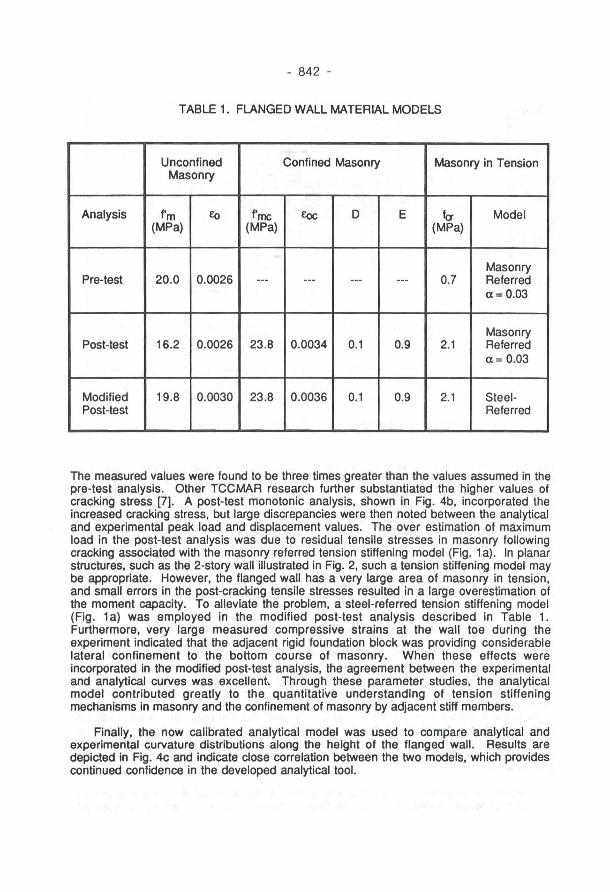
TABLE 1. FLANGED WALL MATERIAL MODELS
Unconfined Confined Masonry Masonry in Tension Masonry
Analysis f m f<) rmc €o<: D E fa Model (MPa) (MPa) (MPa)
Masonry Pre-test 20.0 0.0026 --- --- --- --- 0.7 Referred
a= 0.03
Masonry Post-test 16.2 0.0026 23.8 0.0034 0.1 0.9 2.1 Referred
a= 0.03
Modified 19.8 0.0030 23.8 0.0036 0.1 0.9 2.1 Steel-Post-test Referred
The measured values were found to be three times greater than the values assumed in the pre-test analysis. Other TCCMAR research further substantiated the higher values of cracking stress [7). A post-test monotonic analysis, shown in Fig. 4b, incorporated the increased cracking stress, but large discrepancies were then noted between the analytical and experimental peak load and displacement values. The over estimation of maximum load in the post-test analysis was due to residual tensile stresses in masonry following cracking associated with the masonry referred tension stiffening model (Fig. 1 a). In planar structures, such as the 2-story wall iIIustrated in Fig. 2, such a tension stiffening model may be appropriate. However, the flanged wall has a very large area of masonry in tension, and small errors in the post-cracking tensile stresses resulted in a large overestimation of the moment capacity. To alleviate the problem, a steel-referred tension stiffening model (Fig. 1 a) was employed in the modified post-test analysis described in Table 1. Furthermore, very large measured compressive strains at the wall toe during the experiment indicated that the adjacent rigid foundation block was providing considerable lateral confinement to the bottom course of masonry. When these effects were incorporated in the modified post-test analysis, the agreement between the experimental and analytical curves was excellent Through these parameter studies, the analytical model contributed greatly to the quantitative understanding of tension stiffening mechanisms in masonry and the confinement of masonry by adjacent stiff members.
Finally, the now calibrated analytical model was used to compare analytical and experimental curvature distributions along the height of the flanged wall. Results are depicted in Fig. 4c and indicate close correlation between the two models, which provides continued confidence in the developed analytical toeI.

360
300
240 ........ z 180 ::r:: '-"
I-. 120 al
Q)
.c: !Zl 60
Q) a:l al
Q:l O
-60
-120
-180
320
280
Z 240 ::r::
I-. 200 al Q)
.c: !Zl 160
Q) a:l al 120 Q:l
80
40
-75
H lv
I E
E ., N .,
.;
Flange in compression
-50
- 843 -
Flange in tension
E
~
Cyclic analysis Experimenl
-25 O 25 50 Top Displacemenl (mm)
(a) Cyclic Response Comparison ,-------------, 3.6 !i:-----------,
~ Analytical : Yield ~ Analytical: Max Load ~ Analytical: Crushing
Flange in tension
lJS[3(]EI Experimental Envelope -- Post-test analysis -- Moditied post-test -- Pre-test analysis
3.2
2.8
S 2.4 '-"
.... ~ 2.0 'Qj ::t: 1.6 -«i ~ 1.2
0.8
0.4
0.0
- - - Exper.: Yield - - Exper.: Max load
Max curvature at cruabinc: Experimenl: .02236 I m Analyail : .02323 I m
o 10 20 30 40 50 60 10 Top Displacement (mm)
(b) Material Parameter Sludies
0.000 0.002 0.004 0.006 0.008 Curvature (l/m)
(c) Curvalure Dislribution
Figure 4. Flanged Masonry Wall Analysis

- 844 -
CONCLUSIONS
A finite element model was presented which can trace the complete nonlinear response of reinforced masonry systems under simulated seismic loads. In addition to closely predicting the load-deflection history for complex masonry systems, the model can capture crack and yield pattern developments, as well as criticai crushing and ultimate load and deformation limit states. The model was developed under the U.S.-TCCMAR program in direct support of the development of new design guidelines for masonry buildings in seismic zones. The presented analytical model was calibrated and verified using full-scale experimental component test data and was subsequently employed to predict the behavior and criticai response limit states of complex masonry systems tested under fully reversed cyclic loading.
Current work is directed toward the ultimate goal of modeling complete structural systems to be tested in the final phase of the U.S.-TCCMAR programo In order to improve the modeling of T -section walls which can be sensitive to steel properties, an improved cyclic steel model which includes the Bauschinger effect is being implemented. A layered plate element has been implemented and is undergoing calibration with full-scale tests of coupling slab behavior being conducted at UCSD. Proposed work will allow the model to represent the Generated Sequential Displacement load histories used in full-scale tests. When complete, the validated model will be used to predict the response of a five-story full-scale reinforced masonry research building and to provide the required parametric basis for comprehensive design model developments.
REFERENCES
[1] Ewing, R.E., Kariotis, J.C., Englekirk, R.E. and Hart, G.G., "Analytical Modeling for Reinforced Masonry Buildings and Components - TCCMAR Category 2 Program," Proceedjngs of the 4th North Amerjcan Masoncy Conference, Vol. 11, The Masonry Society, Los Angeles, CA, August 1987.
[2] Vecchio, F.J., "Nonlinear Finite Element Analysis of Reinforced Concrete Membranes," AC I Structural Journal, Vol. 86, No. 1, 1986.
[3] Seible, F., LaRovere, H.L., and Kingsley, G.R., "Nonlinear Analysis of Reinforced Concrete Masonry Shear Wall Structures - Monotonic Loading," The Masoncy Socjety Jmmlal, Vol. 9, No. 2, August 1990, pp. 60-69.
[4] Seible, F., LaRovere, H.L., and Kingsley, G.R., "Nonlinear Analysis of Reinforced Concrete Masonry Shear Wall Structures - Cyclic Loading," The Masoncy Socjety Journal, Vol. 9, No. 2, August 1990, pp. 70-77.
[5] Leiva, G., Merryman, M. and Klingner, R.E., "Design Philosophies for Two-Story Concrete Masonry Walls with Door and Window Openings," proceedjngs of the 5th North Amerjcan Masoncy Conference, University of lIIinois, Urbana-Champaign, June 1990.
[6] Priestley, M.J.N. and He L., "Seismic Response of T-Section Masonry Shear Walls," proceedjngs of the 5th North Amerjcan Masoncy Conference, University of lIIinois, Urbana-Champaign, June 1990.
[7] Hamid, A.A., Bechara E.A., Muris, W.F., Mickel, K.H., Harris, H.G., "Response of Reinforced Block Masonry Walls to Out-of-Plane Static Loads," TCCMAR Report No. 3.2(a), September 1989.