predicting optimized edm machining parameter through ... - … · relation between input and output...
TRANSCRIPT

IOSR Journal of Mechanical and Civil Engineering (IOSR-JMCE)
e-ISSN: 2278-1684,p-ISSN: 2320-334X, Volume 13, Issue 3 Ver. V (May- Jun. 2016), PP 71-85
www.iosrjournals.org
DOI: 10.9790/1684-1303057185 www.iosrjournals.org 71 | Page
Predicting Optimized EDM Machining Parameter through
Thermo Mechanical Analysis
AbhinandanA. Gosavi#, Prof.A. B. Gaikwad
#
#Department of Mechanical Engineering,Dr. D. Y. Patil School of engineering, Charholi(Bk), Pune-
412105,SavitribaiPhule Pune University.
Abstract: Electrical discharge machining (EDM) is one of the earliest non-traditional machining processes.
EDM process is based on thermo electric energy between an electrode and the workpiece. The important
process parameters in this technique are current, discharge pulse on time, discharge pulse off and gap
voltage. The values of these parameters significantly affect the machining outputs material removal rate.
Optimization is one of the techniques used in manufacturing sectors to arrive for the best manufacturing
conditions, which is an essential need for industries towards manufacturing of quality products at lower cost
also due to difficulty of EDM, for improving cutting performance.it is very complicated to determine optimal
cutting parameters, which is an important action in machining and modelling is necessary to make a precise
relation between input and output parameters. In the present research, an axisymmetric thermo-physical finite
element model for the simulation of single sparks machining is presented to analyse the process parameters
and their effect on important responses such as material removal rate on work piece material OHNS Die steel
(EN31) in electrical discharge machining (EDM) process and the model has been solved by using ANSYS 16.0
software. The model is validated conducting experiments on an EDM machine. To study the performance of
machining before actual cutting operation this numerical method provides an inexpensive and time saving
alternative solution. A transient thermal analysis assuming a Gaussian distribution heat source with
temperature-dependent material properties has been used to investigate the temperature distribution on the
surface. Material removal rate (MRR) was calculated for multi-discharge machining by taking into
considerations the number of pulses. Comparison of the theoretical result ,experimental result and ANN
process model result by considering the same process parameters has been done, and the result is highly
agreed between the experimental and theoretical value.
Keywords: Finite element approach, Numerical Analysis; Electrical Discharge Machining; Modeling,
Optimization Process
I. Introduction Electrical discharge machining is a thermal process that involves melting and vaporization of the
workpiece electrode. It is widely used in the aerospace, mould making and die casting industries for
manufacturing plastics moulds, forging dies and die casting dies made from hardened tool steels, together with
engine components, such as compressor blades made from titanium alloys and nickel-based super alloys. The
EDM process uses electrical discharges to remove material from the workpiece, with each spark producing a
temperature of between 10,000-20,000°C. Consequently, the workpiece is subjected to a heat affected zone
(HAZ) the top layer of which comprises recast material. The thickness, composition and condition of this layer
depend on the discharge energy and the make-up of the workpiece, tool electrode and dielectric fluid, and both
hard and soft surface layers can be produced despite perceived wisdom that the recast layer is always hard. Also
it can be defined as process of material removal by controlled erosion through a series of electric sparks.
Electrical energy is used to generate electrical spark and material removal mainly occurs due to thermal energy
of the spark. EDM can be used to machine difficult geometries in small batches or even on job-shop basis. Work
material to be machined by EDM has to be electrically conductive:
The complex nature of the process involving behavior of the EDM spark makes it even tougher to
analyze the process experimentally and quantifies the process responses. The frequencies of an original shape
and modified shape should be within range. The process has however, some limitations such as high specific
energy consumption, longer lead times and lower productivity which limit its applications. Researchers
worldwide are thus, focusing on process modeling and optimization of EDM to improve the productivity and
finishing capability of the process
Due to the complex and non-linear relationship between the input process parameters and output
performance parameters, it is quite difficult to develop an accurate process model and use it to select the
optimum process parameters for EDM process. The focus of the present work is thus, on developing an
intelligent approach for process modeling and optimization of EDM process and to predict process responses
such material removal rate (MRR) from the process parameters. Physics based process modeling using FEM has

Predicting Optimized EDM Machining Parameterthrough Thermo Mechanical Analysis
DOI: 10.9790/1684-1303057185 www.iosrjournals.org 72 | Page
been used to improve prediction accuracy of the model with less dependency on the experimental data. This
approach will help a process engineer to improve the process productivity, finishing capability and economical
operation of die-sinking EDM process.
II. Literature Review According to Vinothkumar.S, “Electro Thermal Modelling of Micro EDM”, he analyzed in his
investigation of Finite element modelling of RC-circuit Micro-EDM process has been carried out to predict the
MRR using Finite element analysis software ANSYS (v.12). This model considers Capacitance, Resistance and
Voltage to predict temperature distribution on the workpiece. The results have been verified with the
experimental investigation performed with the pure copper as the tool electrode and AISI 304 stainless steel as
the workpiece. [1]
According to Chinmaya P. Mohantya*, JambeswarSahub, S.S.Mahapatraa “Thermal-structural
Analysis of Electrical Discharge Machining Process” In the his present work, a thermal-structural model is
presented to analyze the process parameters and their effect on three important responses such as material
removal rate, tool wear rate and residual stresses on work piece in electrical discharge machining (EDM)
process.A Box-Behnkin design of response surface methodology is adopted to collect data for analysis.
Regression analysis is conducted to develop equations relating responses with process parameters. Finally, non-
dominated sorting genetic algorithm is used to obtain pareto optimal solution for multi objective optimization.
[2]
According to S.N. Joshi, S.S. Pande, “Thermo-physical modeling of die-sinking EDM process” This
paper reports the development of a thermo-physical model for die-sinking electric discharge machining (EDM)
process using finite element method (FEM). Numerical analysis of the single spark operation of EDM process
has been carried out considering the two-dimensional axi-symmetric process continuum.[3]
According to C.K.Biswas, “Thermal-Electrical Modelling of Electrical Discharge Machining Process”
In the present work, the Joule heating factor was used to model the EDM process and predict the maximum
temperature reached in the discharge channel. From the temperature distribution the volume of material
removed from the work piece and Rmax was estimated. Experiments were conducted with different pulse on-
time (Ton) and current values and the material removal rate was calculated.[4]
III. Problem Statement and Objective In EDM process, the pulse on time, peak current and Voltage are very important machining parameters
because it can control material remove rate. However, there are difficulties to determine the optimum machining
parameter to increase the material remove rate. The unsuitable pulse duration and peak current will increase the
cost of production. Besides that, adding the dielectric fluid flushing process will increase the material remove
rate. In this study, we will determine the optimum machining parameters to increase material remove rate.To
calculate Material removal Rate (MRR) of OHNS Die steel in order to get accuracy/ surface integrity of
machined work piece
IV. Theoretical Analysis
A.Numerical modeling of the EDM process
To obtain the relationship between pulse conditions and material removal rate, many attempts have
been made to calculate temperature distribution in the electrodes caused by a single pulse discharge by solving
time-dependent heat transfer equations assuming various heat source models. Based on the mathematical
models, the temperature profile due to the passage of an individual pulse can be created.However the scope of
such analysis is limited; a more comprehensive approach is needed.
Joshi and Pande’s Model [3] considers more realistic assumptions for thermal analysis in EDM
process. So it can be considered as best available, realistic and reliable thermal model for the further work of
development in EDM process. Thus this model is the taken as benchmark for the present work of stress analysis.
B.EDM spark
In EDM, the tool (anode) and the work piece (cathode) are immersed in a dielectric medium separated
from each other by a small gap. A controlled spark is generated between the two electrodes by applying a
voltage which breaks down the dielectric medium causing the voltage fall. The on- time of EDM spark (of the
order of microseconds), electrons start flowing from cathode to anode which ionizes the dielectric medium and
form a plasma channel between the cathode and anode. The intense heat generated in the plasma channel melts
and even vaporizes some of the work and tool material causing material removal. The molten metal is held back
at its place due to the large plasma pressure and as soon as the spark on-time is over (the spark collapse) the
dielectric gushes back to fill the void. This sudden removal of pressure results in a violent ejection of the molten
metal from the work surface forming small craters at locations, where material has been removed. [5]

Predicting Optimized EDM Machining Parameterthrough Thermo Mechanical Analysis
DOI: 10.9790/1684-1303057185 www.iosrjournals.org 73 | Page
Fig. 1 Schematic representation of the domain considered for the numerical model
C. Process and boundary conditions
The primary mechanism of material removal in EDM process is the thermal heating of work surface
due to intense heat generated by the plasma, which raises the temperature of the electrodes (tool, work) beyond
their melting point, sometimes even the boiling point. During the process, spark discharges may occur over
work surface at locations where the inter electrode gap is minimum. Figs. 1 and 2 show the two-dimensional
axi-symmetric process continuum and the associated boundary conditions taken for the analysis. Following
assumptions have been made during the thermal Analysis.
Assumptions
1. Work piece and tool materials are homogeneous and isotropic in nature.
2. The material properties of the workpiece and tool are temperature dependent.
3. During the EDM operation, heat is transferred from plasma to electrodes by conduction and radiation, while
from plasma to dielectric by convection and radiation. In the present work, the primary mode of heat
transfer between plasma and electrodes is considered to be conduction.
4. EDM spark channel is considered as a cylindrical column and the spark radius is assumed to be a function
of discharge current and time.
5. Gaussian distribution is taken for heat flux. The influence of the spark zone is taken to be axi-symmetric in
nature.
6. Out of total spark some of total spark energy is dissipated as heat into the work piece, the rest is lost into the
dielectric convection and radiation.
7. Flushing efficiency is considered as 100%. On the machined surfaces there is no deposition of recast layer.
Fig. 2 Process continuum and boundary conditions
D. Governing equation
For the transient, non-linear thermal analysis of EDM process, Fourier heat conduction equation is taken as the
governing equation 1 1
𝑟
𝜕
𝜕𝑟 𝐾𝑡𝑟
𝜕𝑇
𝜕𝑟 +
𝜕
𝜕𝑧 𝐾𝑡
𝜕𝑇
𝜕𝑧 = 𝜌𝐶𝑃
𝜕𝑇
𝜕𝑡 (1)

Predicting Optimized EDM Machining Parameterthrough Thermo Mechanical Analysis
DOI: 10.9790/1684-1303057185 www.iosrjournals.org 74 | Page
Where r and z are the coordinates of cylindrical work domain; T is temperature; Kt is thermal
conductivity; ρis density and Cp is specific heat capacity of work piece material. Fig. 2 shows the applied
boundary conditions applied. In EDM machining process, the work piece is immersed in dielectric medium; the
temperature of the domain is thus assumed to be ambient temperature (ta) to start with. The top surface of the
workpiece is in contact with the dielectric medium at (boundary 2).On this surface the Heat flux (q) boundary
condition is applied.
Heat input
The factors which contribute to the accurate calculation of the MRR in single spark EDM model
include the radius of plasma spark, amount of heat input and the thermo-physical properties of material. These
models are simplistic in actual practice neither isthere any uniform application of heat on the work piece nor is
there a point heat source. At the cathode electrode a spark radius exists. Consideration of average thermo-
physical material properties and constant EDM spark radius make the available models simplistic and less
accurate in predictions.
The Gaussian distribution of heat flux input has been used to approximate the heat from the plasma. Due to
EDM spark is given by the heat q entering the workpiece,
𝑞(𝑟) = 𝑞𝑜𝑒𝑥𝑝 −4.5 𝑟
𝑅𝑝𝑐 2
(2)
Using this equation, the maximum heat flux can be calculated as under.
𝑞𝑜 =4.57𝐹𝐶𝑉𝐼
𝜋𝑅𝑃𝐶2 (3)
where𝐹𝑐 is fraction of total EDM spark power going to the cathode; V is discharge voltage; I is discharge current
and 𝑅𝑝𝑐 is spark radius at the work surface.
Spark radius
Spark radius is an important factor in the thermal modeling of EDM process. In practice, it is extremely
difficult to experimentally measure spark radius due to very short pulse duration of the order of few
microseconds. The equations proposed by these researchers are not realistic in nature as the EDM spark is
controlled both by discharge energy and discharge on-time have derived a semi-empirical equation of spark
radius termed as ``equivalent heat input radius'' which is a function of discharge current, I (A) and discharge on-
time, 𝑡𝑜𝑛 𝜇𝑠 Eq. (4)). It is more realistic when compared with the other approaches.
𝑅𝑝𝑐 = 2.04𝑒 − 3 𝐼0.43𝑡𝑜𝑛0.44 𝜇𝑚 (4)
In the present work, this approach has been used to calculate the equivalent heat input at cathode using
Eqs. (2) and (4). The heat flux equation derived and used for further analysis in this work is,
𝑞(𝑡) =3.4875×10⁵𝐹𝐶𝑉𝐼
0.14
𝑡𝑜𝑛0.88 𝑒𝑥𝑝 −4.5
𝑡
𝑡𝑜𝑛 0.88
(5)
Where𝐹𝑐 is the fraction of total power going to the cathode; V is the discharge voltage; I is the
discharge current; t is the time 𝜇𝑠 and 𝑡𝑜𝑛 is time 𝜇𝑠 at the end of electric discharge. Eq. (5) controls the
amount of heat which is applied on the cathode which in turn, causes removal of material from cathode during
operation.
The governing equation (Eq. (1)) with boundary conditions outlined earlier was solved by FEM to
predict the temperature distribution at the end of each transient heat transfer analysis cycle. ANSYSTM16.0, a
FEM solver was used. A two-dimensional continuum of size ten times the spark radius was considered for the
analysis. Four-noded, axi-symmetric, thermal solid element (PLANE 55) was used for discretization of the
continuum. The transient heat transfer problem was solved by applying the heat flux at the spark location (Eq.
(5)) and using the discharge duration as the time step for the analysis. Fig. 7 shows the results for a typical
problem showing the temperature contour plots. The results are for work material OHNS END31 die tool steel
with machining conditions discharge current 6 A, discharge voltage 40 V and discharge duration of 30s
.
Table I: Maximum heat flux over the spark radius
Sr No Current ( Ip) Pulse ON (time) Voltage Q in for Analysis
1 6 75 40 4834.914965
From the calculations of maximum heat flux over the spark radius we have calculated the heat flux for case 1 as
4834.9 W/mm2.

Predicting Optimized EDM Machining Parameterthrough Thermo Mechanical Analysis
DOI: 10.9790/1684-1303057185 www.iosrjournals.org 75 | Page
Results for the case 1 while modelling the complete workpiece plate (OHNS) En31 of Size 100mm
×80mm×16mm. Minimum Meshing size is limited by the large geometry that we have to mesh. So minimum
Mesh size used is 0.1 mm.
Plane Axisymmetric modelling approach is used from ANSYS 16. Below are the images of axisymmetric
geometry and meshing with some results plots.
Fig.3 - Axisymmetric Sketch for Work Piece Complete
Fig4: - Loading Condition for Thermal Transient Analysis
Table II:Loading condition Time Q ( W/mm2)
0 3301
7.50E-05 3301
2.3E-04 0

Predicting Optimized EDM Machining Parameterthrough Thermo Mechanical Analysis
DOI: 10.9790/1684-1303057185 www.iosrjournals.org 76 | Page
Fig5: Meshing
Fig6: Zoomed View meshing

Predicting Optimized EDM Machining Parameterthrough Thermo Mechanical Analysis
DOI: 10.9790/1684-1303057185 www.iosrjournals.org 77 | Page
Results plots for the same is shown below
Fig7: Temperature Distribution Plot case 1
From Above FEA plot it is clear that we can reduce the size of the sample material taken to very small
dimensions. For next analysis we will consider only 2 mm radius and 2 mm height cylinder, represented by
axisymmetric model of 2 mm square geometry. From next case melting temperature for SS431 material is
1540ᴼC we need to calculate the volume removed in single on off cycle to get Volume removal rate
V. Finite Element Analysis To calculate the material removal due to single spark discharge, the cavity volume was divided into
number of cylindrical discs (Fig. 8). The x-y coordinates of the node boundary are calculated from ANSYS
WORKBENCH file.
Fig.8:Calculation of crater volume

Predicting Optimized EDM Machining Parameterthrough Thermo Mechanical Analysis
DOI: 10.9790/1684-1303057185 www.iosrjournals.org 78 | Page
Total crater volume𝐶𝑣𝑡 𝑚𝑚3 is given by,
𝐶𝑣𝑡= 𝐷𝑖𝑛−1𝑖=0 (6)
Where volume of a disc, 𝐷𝑖 is given by,
𝐷𝑖 = 𝜋 𝑋𝑖+𝑋𝑖+1
2 2 𝑦𝑖+1 − 𝑦𝑖 (7)
Where x and y are the coordinates of nodes and n is the number of nodes. Eqs. (6) and (7) were used to calculate
the crater volume generated by a single spark discharge. MRR was computed for chosen process conditions
considering that all sparks are equally effective with 100% dielectric flushing efficiency. The MRR 𝑚𝑚3/𝑚𝑖𝑛 is computed by,
𝑀𝑅𝑅 =60×𝐶𝑣𝑡
𝑡𝑜𝑛 +𝑡𝑜𝑛 (8)
Table III.MMR for Case I Node No X(mm) Y(mm) Di 𝐶𝑣𝑡 MMR
1 0.00000E+00 1.98800E+00 1.41372E-07 7.28177E-05 14.56
2 1.50000E-02 1.98880E+00 7.12513E-07
3 2.10000E-02 1.98950E+00 1.26669E-06
4 2.70000E-02 1.99020E+00 2.15026E-06
5 3.15000E-02 1.99100E+00 2.50493E-06
6 3.60000E-02 1.99170E+00 3.53429E-06
7 3.90000E-02 1.99250E+00 3.60710E-06
8 4.20000E-02 1.99320E+00 4.75574E-06
9 4.50000E-02 1.99400E+00 1.05207E-05
10 4.95000E-02 1.99550E+00 1.26201E-05
11 5.40000E-02 1.99700E+00 6.59198E-06
12 5.55000E-02 1.99770E+00 2.44120E-05
13 6.07500E-02 2.00000E+00
Where 𝐶𝑣𝑡 the material is removed per discharge pulse;𝑡𝑜𝑛 is discharge duration and𝑡𝑜𝑓𝑓 is the discharge
off-time. T on time is 75 microseconds and T off time is 225 microseconds Actual reading recorded from
machine was 13 𝑚𝑚3/min.
Table IVMMR for Case I Exp. No Discharge current
(A)
Pulse ON time
(µs)
Pulse OFF time
(µs)
Voltage MRR MRR BY ANSYS Error %
6 75 225 40 13.27 14.56 9.75%
9.75% error is observed in case 1 for sample case all the calculations are displayed for first case. For rest of the
cases temperature plots and table for the values will be provided directly.
Fig 9: Temperature Distribution Plot case 2
Predicting Optimized EDM Machining Parameterthrough Thermo Mechanical Analysis
DOI: 10.9790/1684-1303057185 www.iosrjournals.org 79 | Page
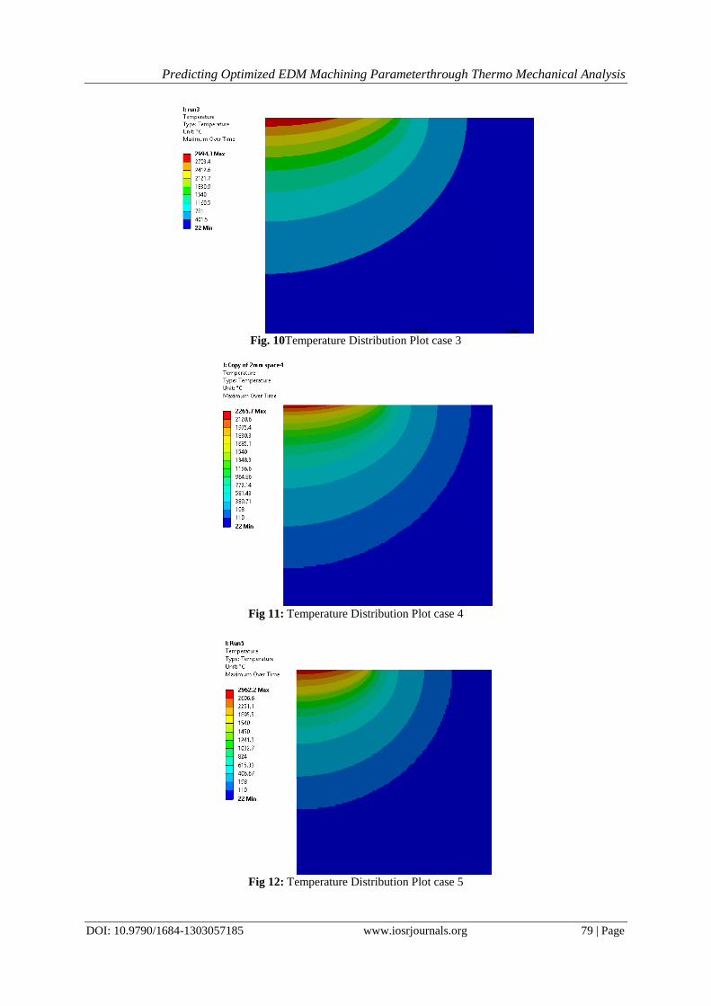
Fig. 10Temperature Distribution Plot case 3
Fig 11: Temperature Distribution Plot case 4
Fig 12: Temperature Distribution Plot case 5

Predicting Optimized EDM Machining Parameterthrough Thermo Mechanical Analysis
DOI: 10.9790/1684-1303057185 www.iosrjournals.org 80 | Page
Fig 13: Temperature Distribution Plot case 7
Fig 14: Temperature Distribution Plot case 8
Fig15: Temperature Distribution Plot case 9

Predicting Optimized EDM Machining Parameterthrough Thermo Mechanical Analysis
DOI: 10.9790/1684-1303057185 www.iosrjournals.org 81 | Page
Table VMMR for all Case Exp.
No
Discharge current
(A)
Pulse ON time
(µs)
Pulse OFF
time (µs)
Voltage MRR
(from machine
manual)
MRR BY
ANSYS
Error %
(mm3/mm)
1 6 75 225 40 13.27 14.56 9.75
2 6 100 250 45 21.75 23.5 8.07
3 6 150 450 50 25.04 29.33 17.13
4 8 75 225 45 20.19 20.85 3.27
5 8 100 250 50 37.82 43.11 13.98
6 8 150 450 40 35.55 39.47 11.02
7 12 75 225 50 45.7 47.5 3.94
8 12 100 250 40 52.33 58.37 11.55
9 12 150 450 45 52.52 57.43 9.35
VI. Experimental Analysis A.Machine tool
Experiments are carried out using CNC EDM (EMT 43) (Electronica) die sinking machine (shown in
fig 3.2). Table 3.2 shows the specification of die sinking EDM machine.
Table VMMR for all Case Machining Conditions
Machine Used EDM (model 5535) (Electronica)
Electrode Electrode Copper (99.9% Purity)
Electrode Polarity Positive
Work piece Oil Hardened Non Shrinking Steel (48-50 Rc)
Dielectric EDM Oil
Flushing Condition Pressure Flushing through 6 mm hole through work piece
B. Work piece material
OHNS (EN 31) PLATE tool steel Size of 100mm ×80mm ×16mmlength size has been used as a work
piece material for the present experiments. The chemical composition and mechanical properties of the work-
piece materials are shown in Table VI and Table VII
Table ViChemical composition of EN 31 Tool Steel Electrode Chemical composition (wt. %)
C 1.07
Mn 0.58
Si 0.32
P 0.04
Si 0.03
Cr 1.12
Fe 96.84
Table ViiMechanical properties of EN 31 Tool Steel EN 31 Tool Steel
Thermal Conductivity 𝑤/𝑚𝑘 46.6
Density 𝑔𝑚/𝑐𝑐 7.81
Electrical Resistivity 𝑜𝑚𝑐𝑚 0.0000218
Specific heat capacity (j/gm.-℃ 0.475
Fig16: Work piece material before machining

Predicting Optimized EDM Machining Parameterthrough Thermo Mechanical Analysis
DOI: 10.9790/1684-1303057185 www.iosrjournals.org 82 | Page
Fig17: Work piece material after machining
C.Electrode material
An electrolytic pure copper with 12 mm X 30 mm is used as a tool electrode (positive polarity). Copper shows
good response in metal removal rate toward high values of discharge current, due to increase in thermal
conductivity and electrical conductivity of copper. The mechanical properties of the tool materials (electrode)
are shown in Table VIII.
.Table ViiiMechanical properties of Electrode Copper (99% pure)
Thermal Conductivity 𝑤/𝑚𝑘 391
Density 𝑔𝑚/𝑐𝑐 1083
Electrical Resistivity 𝑜𝑚𝑐𝑚 1.69
Specific heat capacity (j/gm-℃ 0.385
Table IxDifferent variables used in the experiment and their levels Response Material Removal Rate (mm3 /min.)
Parameters Tool Wear Rate (mm3 /min.)
Surface Roughness (µm)
Control Parameters Levels
1 2 3
Discharge current (A) 6 8 12
Pulse ON time (µs) 75 100 150
Voltage 40 45 50
D.Experimental results
The material removal rate found in the experiment conducted with varying 𝑇𝑜𝑛 and current values are
shown in Table X. The difference in weights, volume of material removed and material removal rates are
also presented in the table.
Table XMaterial removal rate found in the experiment conducted with varying 𝑇𝑜𝑛 and current values SN Discharge current
(A)
Pulse ON time
(µs)
Voltage Material Removal Rate (experiment) MRR
MRR BY
ANSYS
(mm3/mm)
1 6 75 40 12.75 14.56
2 6 100 45 20.22 23.5
3 6 150 50 24.78 29.33
4 8 75 45 21.52 20.85
5 8 100 50 38.42 43.11
6 8 150 40 37.58 39.47
7 12 75 50 49.23 47.5
8 12 100 40 60.96 58.37
9 12 150 45 58.53 57.43
Sample Calulation:
For Ton=75, the Material removal rates at 4 different current values are:
Current = 6 Amperes
The initial weight of the sample=580.43 grams
After machining, the final weight=580.001 grams

Predicting Optimized EDM Machining Parameterthrough Thermo Mechanical Analysis
DOI: 10.9790/1684-1303057185 www.iosrjournals.org 83 | Page
Weight loss = 580.43-579.229 (grams) = 1.201 grams
Volume Loss = Weight loss/Density
= 1.201/0.00785
=152.99𝑚𝑚3
Material Removal Rate = Volume of the material removed/Time = 152.99/12
=12.75 mm3/min.
Fig. 18 Experimental setup
Fig. 19 EDM machine View

Predicting Optimized EDM Machining Parameterthrough Thermo Mechanical Analysis
DOI: 10.9790/1684-1303057185 www.iosrjournals.org 84 | Page
VII. Intelligent process modeling using ANN Artificial Neural Network (ANN) is well known due to their ability to approximate non-linear and
complex relationship between process parameters. It was, therefore, thought appropriate and convenient to
develop a comprehensive (4 inputs – 1 output) EDM process model using ANN for quicker and accurate
prediction of process performance results. A comprehensive process model of EDM was developed using ANN
to accurately predict the process responses viz. MRR.
Table XMaterial removal rate found in the ANN Process modelling SN Discharge current
(A)
Pulse ON time
(µs)
Voltage Material Removal Rate (experiment) MRR
MRR BY
ANN
(mm3/mm)
1 6 75 40 12.75 12.79
2 6 100 45 20.22 20.43
3 6 150 50 24.78 24.75
4 8 75 45 21.52 19.75
5 8 100 50 38.42 35.57
6 8 150 40 37.58 37.59
7 12 75 50 49.23 49.23
8 12 100 40 60.96 60.95
9 12 150 45 58.53 58.54
VIII. Results and Discussion
Fig20: Comparisons between Experimental MRR, FEM and ANN calculated MRR
Taking En-31 (OHNS) as workpiece material with single spark the results have been obtained. From
Table X, it clear that the values of the responses predicted by numerical model are closer to the experimental
results. Thus, it can be concluded that the numerical model would give better prediction of process responses
compared to the earlier reported models. Temperature distribution in the workpiece has been shown in Fig. 7.
From the simulation result it is clear evident that at the center line, on the top surface of the workpiece highest
temperature generates. The high temperature rises during the spark on time can easily melt the material and
formed a dome in the work piece. This is evident from the temperature distribution after material removal in
FEA model as shown in Fig. 8. The volume of metal remove depends on amount of heat energy induced in the
material. Therefore the MRR increase in both increase in current and voltage. Fig 20 shows the graphical
representation of MRR obtained in FEM model and experimentally. Experimental result is almost equal to the
predicted MRR obtained by FEM model.
IX. Conclusion In the present a numerical approach is presented in this work to estimate material removal rate on work
piece in EDM process. The results obtained by numerical analysis and experimental methods have been
compared. It can be concluded that numerical method provides reasonably accurate estimation of responses.
Therefore, the method can be adopted to predict the responses before going for actual cutting operation. It may
save time and cost of experimentation work. For developing such model various important process parameters
are taken into account such as pulse on/off time, material properties, shape and size of heat source and heat

Predicting Optimized EDM Machining Parameterthrough Thermo Mechanical Analysis
DOI: 10.9790/1684-1303057185 www.iosrjournals.org 85 | Page
energy given as input to the work piece. The proposed model can be used for selecting ideal process states to
improve EDM process efficiency and finishing capability.
Acknowledgment I take this opportunity to thanks Prof A. B. Gaikwad and Prof. A. N. Patil for valuable guidance and for
providing all the necessary facilities, which were indispensable in completion of this work. Also I sincerely
thanks to all the authors who worked on optimization of EDM process.
References [1]. Vinothkumar.S, “Electro Thermal Modelling of Micro EDM “International Journal of Innovative Research in Science, Engineering
and Technology (An ISO 3297: 2007 Certified Organization) Vol. 3, Issue 5, May 2014
[2]. Chinmaya P. Mohantya*, JambeswarSahub, S.S.Mahapatra,” Thermal-structural Analysis of Electrical Discharge Machining
Process” Procedia Engineering 51 ( 2013 ) 508 – 513 [3]. S.N. Joshi, S.S. Pande,”Thermo-physical modeling of die-sinking EDM process”, Journal of Manufacturing Processes 12 (2010)
45-56.
[4]. M.R Pradhan, “Modelling and Simulation of Thermal Stress in Electrical Discharge Machining Process, Proc. Of the 4th International Conference on Advances in Mechanical Engineering ,September 23-25,2010 S.V. National Institute of Technology,
Surat-395 007, Gujarat, India
[5]. Jaydeep S. Kevadiya,P. S. Balaji, “A Review On Thermal Analysis Of Electro Discharge Machining” International Journal of Engineering Research & Technology (IJERT) ISSN: 2278-0181 Vol. 2 Issue 4, April – 2013
[6]. C.K.Biswas “THERMAL-ELECTRICAL MODELLING OF ELECTRICAL DISCHARGE MACHINING PROCESS” Department
of Mechanical Engineering National Institute of Technology Rourkela 2007 [7]. Kamlesh Joshi,Gaurav Sharma, Ganesh Dongre, Suhas S. Joshi “Modeling of Wire EDM slicing process for Silicon” ,4Department
of Mechanical Engineering, Indian Institute of Technology Bombay, Mumbai, 400076
[8]. Kumar Sandeep “Current Research Trends in Electrical Discharge Machining: A Review” Dept. of Mechanical Engineering, University Institute of Engineering and Technology, MD University, Rohtak-124001, Haryana, INDIA Research Journal of
Engineering Sciences Vol. 2(2), 56-60, February (2013) ISSN 2278 – 9472 Res. J. Engineering Sci.
[9]. Sandeep Kumar “ Status of recent development and research issues of electrical discharge , machining (EDM)” Assistant Professor Department of Mechanical Engineering, University Institute of Engineering and Technology, M.D. University, Rohtak-12400,
Haryana, India
[10]. ShaazAbulais “Current Research trends in Electric Discharge Machining (EDM) :Review International Journal of Scientific &
Engineering Research, Volume 5, Issue 6, June-2014 ISSN 2229-5518
[11]. P. Shankar, “Analysis of spark discharge in EDM process”, M.Tech. thesis, Indian Institute of Technology, Kanpur, 1996
[12]. ANSYS manuals version 10.0. ANSYS TM Inc. USA.