predicting ductile crack growth in engineered structures
TRANSCRIPT

Idaho National Laboratory
Predicting Ductile Crack Growth in Engineered Structures
E. D. Steffler, INEEL F. A. McClintock, MITM. M. Rashid, U.C. DavisR. L. Williamson, INEELQ. R. Lloyd, INEEL
HLW Workshop January 19-20, 2005

Idaho National Laboratory INLHLW Tank Example (Hanford)

Idaho National Laboratory INLSite Specific Structural Problems
• Nominally, 250 High Level Waste (HLW) Storage Tanks (some operating since 1950s)– 304L or 347SS – INEEL
Wall thickness (t) range from 4.5 to 8.0 mm– Carbon steel: A285Gr B, A516, A537 – Savannah River, Richland
Multiple designs t=12.7 mm for Type 1t=15.9 mm for Type 2t=12.7 to 22.2 mm for Type 3
• Environment:– Acid in SS tanks– Alkaline in carbon steel tanks
Large steel tanks containing radioactive waste are susceptible to extensive cracking caused by ground settlement, earthquakes, or accidents.

Idaho National Laboratory INL
Site Specific Structural Problems(Continued)
• Loading condition– Normal operating – including waste retrieval– Design accident – earthquake, fluid sloshing
• Degradation (cracks and thickness reduction)– Corrosion – local/general– SCC
• Consequences of a Failure (only as related to fracture technology)– Safety of Workers and Public– Environmental– Adverse Publicity / Fear

Idaho National Laboratory INLProblem Complexity

Idaho National Laboratory INL
Scientific Concepts and ObjectivesDevelop and validate fracture mechanics models to predict the fracture process for ductile materials in engineered structures.
• Initiation of crack growth• Stable crack growth
– Penetration of wall thickness– Growth in length (2c) direction
• Unstable cleavage cracking

Idaho National Laboratory INL

Idaho National Laboratory INL
• E. D. Steffler, INL Experimental/Numerical• W. R. Lloyd, INL Experimental
• F. A. McClintock, MIT Analytical
• R. L. Williamson, INL Numerical (Commercial Code)
• M. M. Rashid, UC Davis Numerical (Research Code)- Mili Selimotic, UC Davis Graduate Student
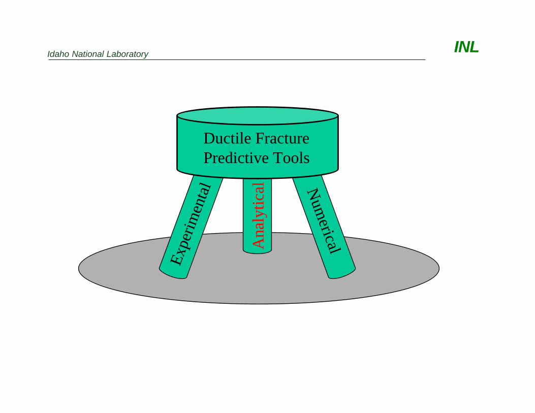
Innovative AspectsThe People coupled with the Approach
Idaho National Laboratory INL
Expe
rimen
tal
Ana
lytic
al Num
erical
Ductile Fracture Predictive Tools

Idaho National Laboratory INL
Analytical ObjectivesIn the analytical studies of this problem, we are focusing on two limiting conditions: 1. The plane strain growth of cracks through the
wall of the tank.2. The lateral growth of through-cracks for many
plate thicknesses in generalized plane stress.(Generalized plane stress means negligible stress in the thickness direction, but in ductile metals it means variable plate thickness from earlier crack growth.)
In both cases, we are considering the statistics of predicting rare transitions from the typical ductile, dimple mode of crack growth to the brittle, cleavage mode, using data from lower temperature tests.

Idaho National Laboratory INL
Crack Front Profile Progress

Idaho National Laboratory INLThe Mechanics of Plane Strain Ductile Crack Growth
The process of fully plastic, plane strain, non-hardening, fracture mechanics.

Idaho National Laboratory INL
SLFM Identified Parameters Used in FEM Comparisons

Idaho National Laboratory INL
Expe
rimen
tal
Ana
lytic
al Num
erical
Ductile Fracture Predictive Tools

Idaho National Laboratory INL

Idaho National Laboratory INL
Z
φ θX
aB
Back surfaceCrack border
c
a = crack depthc = crack half lengthB = plate thickness
Section A-A
A
WL
L/2A
B
(a) Typical surface-crack specimen (grip details omitted)
2c
φ θ= arctan tan ca
CMOD, 2v
a2c
(b) Typical cylindrical configuration (end cap detail omitted) crack on ID or OD
01-GAM0111-03
Surface Crack Specimen Geometries

Idaho National Laboratory INLMicrotopographic Analysis – Capabilities Overview
• Any ductile fracture process/event can be analyzed – test specimen or real structure
• All data collection and analyses occur AFTER the crack growth has happened
• Micron spatial resolution• All ductile fracture CTRFs can be extracted – CTOD, CTOA, etc.
References:• Lloyd, W.R., “Microtopography for ductile
fracture process characterization – Part 1: Theory and methodology,” Engrg. Frac. Mech. 70, pp.387-401, 2003.
• Lloyd, W.R. and McClintock, F.A., “Microtopography for ductile fracture process characterization – Part 2: Application for CTOA analysis,” Engrg. Frac. Mech. 70, pp.403-415, 2003.
• Lloyd, W.R. et al., Microtopographic Analysis of Part-Through Crack Growth in Alloy 304L Plate-type Tension Specimens, INEEL/EXT-03-00495, 2003.
Microtopography scanning system collecting data from one of two opposing fracture surfaces from a large SE(B)-type specimen (B = 50 mm).

Idaho National Laboratory INL
-11 -10 -9 -8 -7 -6 -5 -4 -3 -2 -1 0 1 2 3 4 5 6 7 8 9 10 11Lateral Position (mm)
0
1
2
3
4
5
6
Thro
ugh-
thic
knes
s Po
sitio
n (m
m)
Whole-field Analysis of Incremental Crack Growth
• Contour lines represent incremental crack front positions at crack tip opening increments of 0.5 mm* (overlaid on actual fracture surface picture)
• Purple dye region shows crack front position at point of through-thickness penetration, and confirms accuracy of microtopographic analysis (note excellent correlation of crack front position contour with dye-stained area boundary)
• Fracture surface contrast change marks end of ductile tearing during test – again note excellent correlation of microtopographic prediction of crack tip position
• Gradient analysis of these data provide a whole-field directional CTOA map*last contour increment is 0.2 mm, not 0.5, corresponding to CTOD = 4.2 mm

Idaho National Laboratory INL
-2 0 2 4 6Trajectory Arc Length, S (mm)
(Equivalent to ∆a)
-2
-1
0
1
2Su
rfac
e he
ight
(cra
ck o
peni
ng) (
mm
)
Originalcrack tip,
S = 0
304L PTC #SC-04Trajectory A
CrackOpeningVolume
"Upper" halfmaterial
"Upper"Surface
"Lower"Surface "Lower" half
material
Material displacedby subsequent
plastic flow
Available Info•CTODi•CTOA vs. ∆a•Local CTOA vs. ∆a•CMOD vs. ∆a• ∆CTOD vs ∆a• ∆CTOA vs. ∆a• Φ* vs. ∆a•…others
∗Φ is the crack tip“zig-zag” angle, orinstantaneous growthDirection.Approximate tip location
at state represented inanalysis figure above
“Lower” half fracture surface – red line is crack growth Trajectory A
Trajectory Detail Analysis Snapshot
•Any trajectory can be analyzed
•Data from a family of trajectory analysesare combined to provide a complete 3-Drepresentation of ductile surface crackgrowth, including all parameters at everystate of the fracture process.

Idaho National Laboratory INL
Expe
rimen
tal
Ana
lytic
al Num
erical
Ductile Fracture Predictive Tools

Idaho National Laboratory INL
Computational Modeling of Ductile Fracture: Finite Element Node Release
• Crack extension is achieved by node release along a predefined path
• Release is governed by the Crack Tip Opening Angle (CTOA) at a prescribed distance from the tip along the crack flank
• Initial conceptual testing and model verification has been performed for a simple plane strain extension specimen 2
1
4 mm 6 mmfree
free
free
27.5
mm

Idaho National Laboratory INL
Node Release Model: Investigation of KeyNumerical Parameters
• Key numerical parameters have been investigated by sensitivity study and comparison to analytical solutions
- mesh size (h) near crack extension region
- local CTOA geometry (Ls, δ)
- traction reduction rate at node release
- debond tolerance
• Investigation has provided improved understanding of:
- tradeoffs between numerical accuracy and efficiency
- appropriate numerical parameters to achieve reliable solutions
h
Ls
δ

Idaho National Laboratory INL
Node Release Model: Verification by Comparisonto Analytical Solution
7.687.43δω
43.545Θs
19.9520CTOA
Numerical(FEM)
Analytical(SLFM)
~45 degree slip line
CTOA/2
Θs
δω
Equivalent Plastic Strain

Idaho National Laboratory INLNode Release Model: Application to
Isotropic Hardening Material
BA
ε
σ(M
Pa)
0 0.1 0.2 0.3 0.4 0.50
200
400
600
800
1000
1200316 Stainless Steel
A B

Idaho National Laboratory INLNode Release Model: Developing Improved
Predictive Capability
• From SLFM (McClintock)
CTOA = f (θs, σn/2k)
• ABAQUS user subroutines, currently under development and testing, will permit control of crack extension parameters (e.g. CTOA) based on crack tip driving parameters (e.g., θs, σn) at locations distant from the crack tip so finite element size and material inhomogeneity have negligible effect.
Inhomogeneous or fracture process zone
Validannularzone
Valid annular zone
, 2s n kθ σ
sθ
(<0)netda
sdu
Radiallyconstant
Radiallyvarying
, 2
sn k
θσCTOA

Idaho National Laboratory INLComputational Modeling of Ductile Fracture:
Exclusion Region Theory
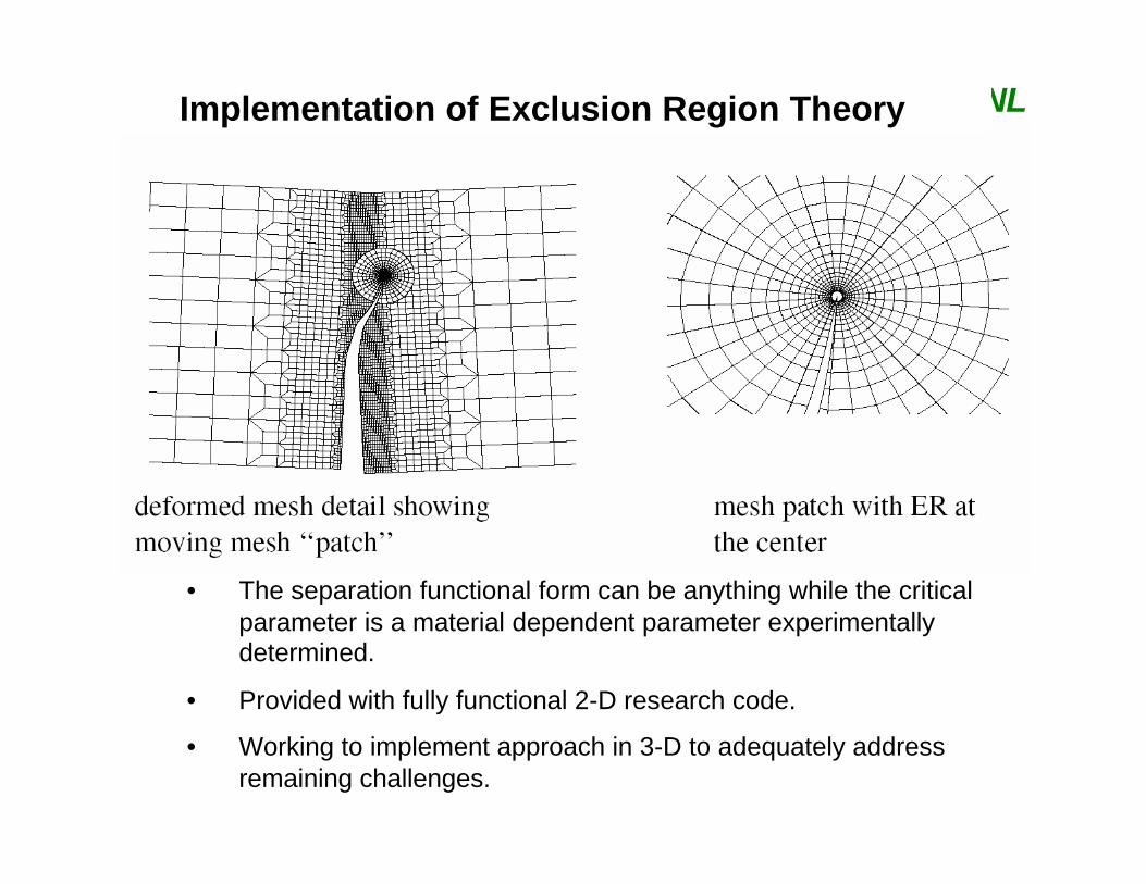
Idaho National Laboratory INLImplementation of Exclusion Region Theory
• The separation functional form can be anything while the critical parameter is a material dependent parameter experimentally determined.
• Provided with fully functional 2-D research code.
• Working to implement approach in 3-D to adequately address remaining challenges.

Idaho National Laboratory INL

Idaho National Laboratory INL

Idaho National Laboratory INLFuture Scientific Directions and Plans• Continue to use concepts of slip-line fracture mechanics
(SLFM) in FEM setting - ductile crack growth criterion guide laboratory experimentation.
• Use the ER theory of fracture with SLFM motivated separation function to capture complex fracture behavior of real ductile metals.
• Complete work on powerful, fully 3-D computational platform - complex nonlinear problems involving crack extension. Two major enabling innovations unique to this research program.
• Exploit the innovative measurement and diagnostic techniques developed at the INL to validate ER-based fracture model. This approach will avoid simplifying idealizations that characterize other research efforts in ductile fracture, and which substantially diminish their technological usefulness.

Idaho National Laboratory INL
Expe
rimen
tal
Ana
lytic
al Num
ericalDuctile Fracture Predictive Tools
Structural Integrity Assurance

Idaho National Laboratory INL
In Conclusion…We have team members that:• understand the technical challenges• have a great deal of interest in working towards
viable solutions to the real-world application• have worked on related problems (structural
integrity, lifetime extension, novel numerical approach)
• have a great deal of relevant experience
Our team is working at the leading edge ofductile fracture predictive technology.

Idaho National Laboratory INL
Acknowledgements and Contact InformationU.S. Department of Energy Basic Energy Sciences and Environmental Management Science Program
Contact Information:Eric D. [email protected] (cell)