precision rolling bearings - ntn snr · c o n t e n t s technical data ntn precision rolling...
TRANSCRIPT
Precision Rolling Bearings
CAT. No. 2260-^/E
R
C O N T E N T S
Technical Data
NTNPRECISIONROLLINGBEARINGS
Main SpindleBearings
Ball Screw SupportBearings
APPENDIX
NTN PRODUCTS
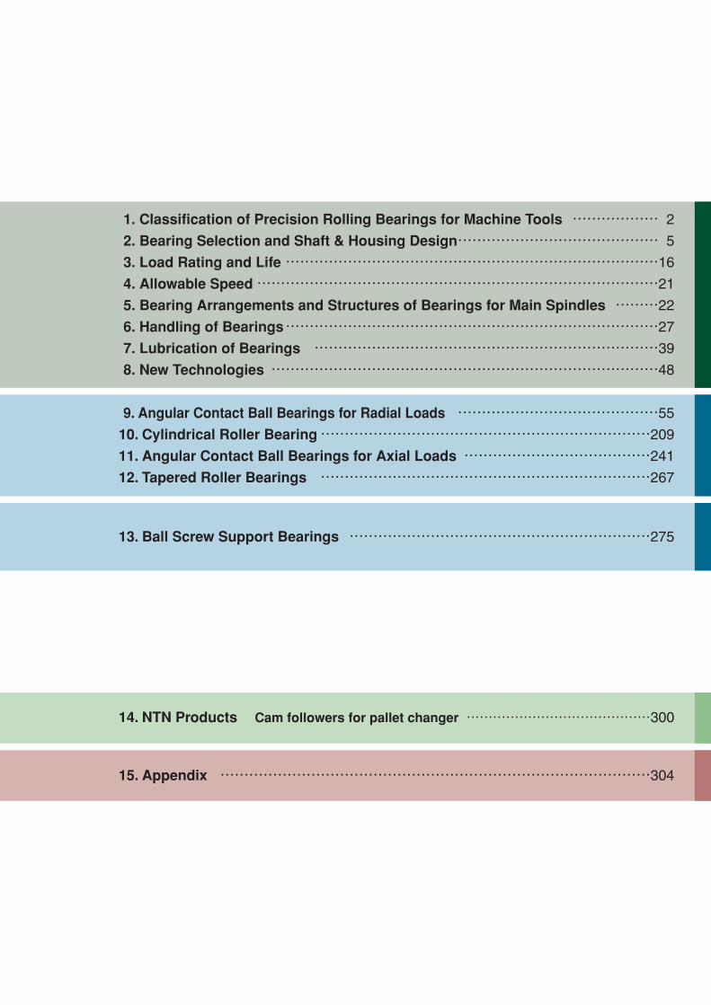
1. Classification of Precision Rolling Bearings for Machine Tools ……………… 2
2. Bearing Selection and Shaft & Housing Design…………………………………… 5
3. Load Rating and Life ……………………………………………………………………16
4. Allowable Speed…………………………………………………………………………21
5. Bearing Arrangements and Structures of Bearings for Main Spindles ………22
6. Handling of Bearings……………………………………………………………………27
7. Lubrication of Bearings ………………………………………………………………39
8. New Technologies ………………………………………………………………………48
9. Angular Contact Ball Bearings for Radial Loads ……………………………………55
10. Cylindrical Roller Bearing……………………………………………………………209
11. Angular Contact Ball Bearings for Axial Loads …………………………………241
12. Tapered Roller Bearings ……………………………………………………………267
13. Ball Screw Support Bearings ………………………………………………………275
15. Appendix ………………………………………………………………………………304
14. NTN Products Cam followers for pallet changer ……………………………………300
Warranty
NTN warrants, to the original purchaser only, that the delivered product which is the subject of this sale (a)will conform to drawings and specifications mutually established in writing as applicable to the contract, and (b)be free from defects in material or fabrication. The duration of this warranty is one year from date of delivery.If the buyer discovers within this period a failure of the product to conform to drawings or specifications, or adefect in material or fabrication, it must promptly notify NTN in writing. In no event shall such notification bereceived by NTN later than 13 months from the date of delivery. Within a reasonable time after suchnotification, NTN will, at its option, (a) correct any failure of the product to conform to drawings, specificationsor any defect in material or workmanship, with either replacement or repair of the product, or (b) refund, in partor in whole, the purchase price. Such replacement and repair, excluding charges for labor, is at NTN'sexpense. All warranty service will be performed at service centers designated by NTN. These remedies arethe purchaser's exclusive remedies for breach of warranty.
NTN does not warrant (a) any product, components or parts not manufactured by NTN, (b) defects causedby failure to provide a suitable installation environment for the product, (c) damage caused by use of theproduct for purposes other than those for which it was designed, (d) damage caused by disasters such as fire,flood, wind, and lightning, (e) damage caused by unauthorized attachments or modification, (f) damage duringshipment, or (g) any other abuse or misuse by the purchaser.
THE FOREGOING WARRANTIES ARE IN LIEU OF ALL OTHER WARRANTIES, EXPRESS OR IMPLIED,INCLUDING BUT NOT LIMITED TO THE IMPLIED WARRANTIES OF MERCHANTABILITY AND FITNESSFOR A PARTICULAR PURPOSE.
In no case shall NTN be liable for any special, incidental, or consequential damages based upon breach ofwarranty, breach of contract, negligence, strict tort, or any other legal theory,and in no case shall total liabilityof NTN exceed the purchase price of the part upon which such liability is based. Such damages include, butare not limited to, loss of profits, loss of savings or revenue, loss of use of the product or any associatedequipment, cost of capital, cost of any substitute equipment, facilities or services, downtime, the claims of thirdparties including customers, and injury to property. Some states do not allow limits on warranties, or onremedies for breach in certain transactions. In such states, the limits in this paragraph and in paragraph (2)shall apply to the extent allowable under case law and statutes in such states.
Any action for breach of warranty or any other legal theory must be commenced within 15 months followingdelivery of the goods.
Unless modified in a writing signed by both parties, this agreement is understood to be the complete andexclusive agreement between the parties, superceding all prior agreements, oral or written, and all othercommunications between the parties relating to the subject matter of this agreement. No employee of NTN orany other party is authorized to make any warranty in addition to those made in this agreement.
This agreement allocates the risks of product failure between NTN and the purchaser. This allocation isrecognized by both parties and is reflected in the price of the goods. The purchaser acknowledges that it hasread this agreement, understands it, and is bound by its terms.
© NTN Corporation. 2015Although care has been taken to assure the accuracy of the data compiled in this catalog, NTN does notassume any liability to any company or person for errors or omissions.

1
Precision Rolling Bearings
TECHNICAL DATACONTENTS
1. Classification of Precision Rolling Bearings for Machine Tools …2〜4q Main spindle bearings …………………………………………………………… 2w Ball screw support bearings ……………………………………………………… 4
2. Bearing Selection and Shaft & Housing Design………………………5〜15q Bearing selection ……………………………………………………………………5w Bearing accuracy ……………………………………………………………………7e Bearings and rigidity ………………………………………………………………11r Designing bearing and housing …………………………………………………14
3. Load Rating and Life…………………………………………………………16〜21q Bearing life …………………………………………………………………………16w Static load rating and allowable axial load………………………………………20
4. Allowable Speed ……………………………………………………………………21
5. Bearing Arrangements and Structures of Bearings for Main Spindles …22〜26q Bearing arrangement for main spindles…………………………………………22w Bearing selection based on bearing arrangement for main spindle …………24e Adjustable preload bearing unit …………………………………………………25r Bearing jacket cooling system……………………………………………………26
6. Handling of Bearings ………………………………………………………27〜38q Cleaning and filling with grease …………………………………………………27w Mounting …………………………………………………………………………28e Tightening of inner ring……………………………………………………………30r Elastic deformation of spacer resulting from tightening force…………………31t Front cover drive-up ………………………………………………………………31y Checking axial rigidity ……………………………………………………………32u Clearance adjustment for cylindrical roller bearing ……………………………33i Cylindrical roller bearing tapered bore and main spindle taper angle ………37o Running-in operation for main spindle bearing…………………………………38
7. Lubrication of Bearings ……………………………………………………39〜47q Grease lubrication …………………………………………………………………40w Air-oil lubrication……………………………………………………………………41e Jet lubrication ………………………………………………………………………47
8. New Technologies ……………………………………………………………48〜53q The new series of super-high-speed precision bearings
for machine tool main spindles "ULTAGE Series" ……………………………48w New material and new surface modification technology ………………………48e Environmentally conscious technology …………………………………………50
Page

2
Technical Data
Table .1 Types of precision rolling bearings for machine tools
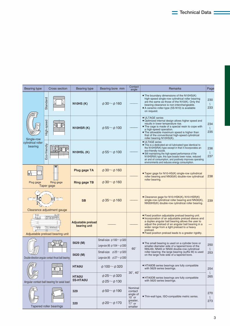
① Main spindle bearings
Bearing type
Angularcontact ball
bearing
Non-contact sealed type
Non-contact sealed type
Double-rowcylindrical roller
bearing
Bearing type Bearing bore mm Contact angle Remarks PageCross section
78C
79 (U), 5S-79 (U)
70 (U), 5S-70 (U)
72C
2LA-HSE9U5S-2LA-HSE9
2LA-HSE05S-2LA-HSE0
5S-2LA-HSF0
5S-2LA-HSFL0
5S-2LA-HSL9U
5S-2LA-HSEW9U
5S-2LA-HSEW0
5S-2LA-HSL0
79 LLB5S-79 LLB
2LA-BNS9 LLB5S-2LA-BNS9 LLB
2LA-BNS0 LLB5S-2LA-BNS0 LLB
BNT95S-BNT9
BNT05S-BNT0
BNT25S-BNT2
NN49 (K)
NNU49 (K)
NN30 (K)NN30HS (K)
NN30HST6 (K)NN30HSRT6 (K)
70 LLB5S-70 LLB
-----
-----
〜
φ25~φ170
φ10~φ170
φ10~φ200
φ10~φ130
φ50~φ170
φ50~φ170
φ50~φ100
φ50~φ100
φ50~φ100
φ10~φ50
φ45~φ100
φ10~φ65
φ10~φ70 15˚
15˚
15˚
25˚
25˚
15˚, 20˚, 25˚
15˚, 20˚, 25˚
20˚, 25˚
20˚, 25˚
15˚, 25˚, 30˚
15˚, 25˚, 30˚
15˚, 25˚
φ10~φ80
φ100~φ320
φ100~φ500
φ25~φ60φ140~φ460
φ65~φ130
84
111
〜112
135
〜136
137
〜138
147
〜156
171
〜148
155
〜172
195
〜196
207
〜224
229
¡The bearing clearance can be either interchangeable radial clearance or non-interchangeable radial clearance.¡A variant (K) is available with a tapered bore to
accommodate a tapered shaft.
¡Angular contact ball bearing series for grinding machines/motors.
¡All variants are flush ground.¡Bearings with prefix 5S have ceramic balls.
Hig
h-sp
eed
Sta
ndar
d
¡ULTAGE series¡Featuring a two-side non-contact seal design and a
special grease, these bearings are a dedicated grease lubricated type that has achieved limited heat buildup through optimization of the interior structure.
¡Bearings with prefix 5S have ceramic balls.
¡ULTAGE series¡High speed angular contact ball bearings with lubrication
hole on outer ring, designed especially for air-oil lubrication based on HSE type. These bearings have an effect on compact design and high rigidity of spindle. Air flow rate and oil consumption can be reduced.
¡Bearings with prefix 5S have ceramic balls.
¡ULTAGE series¡Maintaining the advantages of HSE type, this dedicated
grease lubricated type has an improved interior design (grease reservoir, both -side non-contact seal and special grease) to extend grease life.
¡Bearings with prefix 5S have ceramic balls.
Sta
ndar
dH
igh-
spee
dSu
per h
igh-s
peed
HSE w
ith Lu
bricat
ion ho
leE
co-f
riend
ly
¡A bearing type code containing a suffix U means an ULTAGE series bearing. Optimized interior structure and resin cage help positively inhibit temperature rise (applicable to 79 and 70 types with bore diameter of 10 to 130 mm).
¡Bearings with prefix 5S have ceramic balls.
¡ULTAGE series¡Maintaining the advantages of HSE type, this type has
small diameter ceramic balls to achieve higher speed and limited heat buildup.
¡Bearings with prefix 5S have ceramic balls.
¡ULTAGE series¡Use of special material and introduction of surface
modification contribute to much improved wear resistance and anti-seizure property.
¡Optimized specifications for the interior structure lead to higher speed, rigidity and reliability.
¡Bearings with prefix 5S have ceramic balls.
¡ULTAGE series¡These bearings are identical to the HSE and HSF types
except in that they are air-oil lubrication designs that have an eco-friendly nozzle.
¡Featuring lower noise, reduced air and oil consumption, they positively improve operating environments and reduce energy consumption.
¡Bearings with prefix 5S have ceramic balls.
1. Classification of Precision Rolling Bearings forMachine Tools
3
Technical Data
Angular contact ball bearing for axial load
Double-direction angular contact thrust ball bearing
Tapered roller bearings
Bearing type
Single-rowcylindrical roller
bearing
Taper gage
Clearance adjustment gauge
Adjustable preload bearing unit
Plug gage Ring gage
Bearing type Bearing bore mmContactangle Remarks PageCross section
N10HS (K)
N10HSR (K)
HTA9U
HTA0U5S-HTA0U
5629 (M)
5620 (M)
329
320
-----
-----
-----
-----
-----
----------60 63〜
64
65
φ30~φ160
φ55~φ100
N10HSL (K) φ55~φ100
Plug gage TA
Ring gage TB
SB
Adjustable preloadbearing unit
φ30~φ160
φ30~φ160
φ35~φ160
φ100~φ320
φ25~φ320
φ25~φ130
30˚, 40˚
60˚
φ100~φ320
φ104~φ330
φ25~φ320
φ27~φ330
φ50~φ190Nominalcontactangle of 10˚ orgreater, 17˚ orsmaller
φ20~φ170
〜230
233
〜234
235
〜236
237
238
〜254
265
〜270
273
〜250
253
239
¡The boundary dimensions of the N10HS(K) high-speed single-row cylindrical roller bearing are the same as those of the N10(K). Only the bearing clearance is non-interchangeable.
¡A ceramic-roller-type (5S-N10) is available on request.
¡ULTAGE series¡Optimized internal design allows higher speed and
results in lower temperature rise.¡The cage is made of a special resin to cope with
a high-speed operation.¡The allowable maximum speed is higher than
that of the conventional high-speed cylindrical roller bearing N10HS(K).
¡ULTAGE series¡This is a dedicated air-oil lubricated type identical to
the N10HSR(K) type except in that it incorporates an eco-friendly nozzle.
¡Still maintaining the high-speed performance of the N10HSR(K) type, this type boasts lower noise, reduced air and oil consumption, and positively improves operating environments and reduces energy consumption.
¡Fixed position adjustable preload bearing unit.¡Incorporation of an adjustable preload sleeve and
a duplex angular ball bearing allows the user to adjust the preload of an angular ball bearing in a wider range from a light preload to a heavy preload.
¡Fixed position preload leads to a greater rigidity.
¡The small bearing is used on a cylinder bore or smaller-diameter side of a tapered bore of the NNU49, NN49 or NN30 double-row cylindrical roller bearing; the large bearing (suffix M) is used on the large hole side of a tapered bore.
¡HTA9DB series bearings are fully compatible with 5629 series bearings.
¡Thin-wall type, ISO-compatible metric series.
¡HTA0DB series bearings are fully compatible with 5620 series bearings.
¡Clearance gage for N10-HSK(K) , N10-HSR(K) single-row cylindrical roller bearing and NN30(K), NN30HS(K) double-row cylindrical roller bearing.
¡Taper gage for N10-HS(K) single-row cylindrical roller bearing and NN30(K) double-row cylindrical roller bearing.
Sta
ndar
dH
igh-
spee
dE
co-f
riend
ly
Small-size
Large-size (M)
Small-size
Large-size (M)
4
Technical Data
Angular contact thrust ball bearing for ball screws
Angular contact ball bearing for ball screws
Needle roller bearings with double-directionthrust needle roller bearing
Cylindrical roller bearings withdouble-direction thrust needle roller bearing
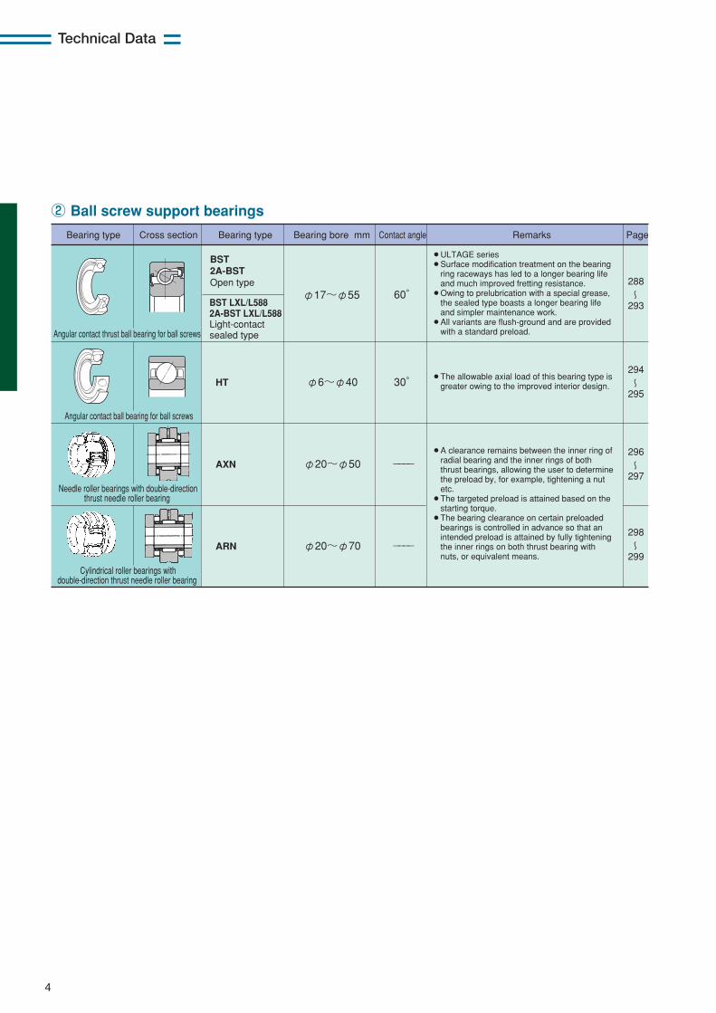
φ17~φ55 60°BST LXL/L5882A-BST LXL/L588Light-contactsealed type
BST2A-BSTOpen type
φ6~φ40 30°HT
φ20~φ50 ----AXN
φ20~φ70 ----ARN
Bearing type Bearing type Bearing bore mm Contact angle Remarks PageCross section
〜288
293
〜294
295
〜296
297
〜298
299
¡ULTAGE series¡Surface modification treatment on the bearing
ring raceways has led to a longer bearing life and much improved fretting resistance.
¡Owing to prelubrication with a special grease, the sealed type boasts a longer bearing life and simpler maintenance work.
¡All variants are flush-ground and are provided with a standard preload.
¡A clearance remains between the inner ring of radial bearing and the inner rings of both thrust bearings, allowing the user to determine the preload by, for example, tightening a nut etc.
¡The targeted preload is attained based on the starting torque.
¡The bearing clearance on certain preloaded bearings is controlled in advance so that an intended preload is attained by fully tightening the inner rings on both thrust bearing with nuts, or equivalent means.
¡The allowable axial load of this bearing type is greater owing to the improved interior design.
② Ball screw support bearings
5
Technical Data
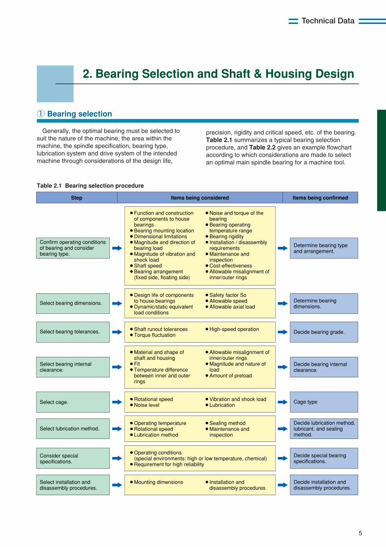
Generally, the optimal bearing must be selected tosuit the nature of the machine, the area within themachine, the spindle specification, bearing type,lubrication system and drive system of the intendedmachine through considerations of the design life,
① Bearing selection
Confirm operating conditions of bearing and consider bearing type.
Determine bearing type and arrangement.
¡Function and construction of components to house bearings ¡Bearing mounting location ¡Dimensional limitations ¡Magnitude and direction of bearing load ¡Magnitude of vibration and shock load ¡Shaft speed ¡Bearing arrangement (fixed side, floating side)
¡Noise and torque of the bearing ¡Bearing operating temperature range ¡Bearing rigidity ¡Installation / disassembly requirements ¡Maintenance and inspection ¡Cost-effectiveness ¡Allowable misalignment of inner/outer rings
Select bearing dimensions. Determine bearing dimensions.
¡Design life of components to house bearings ¡Dynamic/static equivalent load conditions
¡Safety factor So ¡Allowable speed ¡Allowable axial load
Step Items being considered Items being confirmed
Select bearing tolerances. Decide bearing grade.¡Shaft runout tolerances ¡Torque fluctuation
¡High-speed operation
Select bearing internal clearance.
Decide bearing internal clearance.
¡Material and shape of shaft and housing ¡Fit ¡Temperature difference between inner and outer rings
¡Allowable misalignment of inner/outer rings ¡Magnitude and nature of load ¡Amount of preload
Select cage. Cage type¡Rotational speed ¡Noise level
¡Vibration and shock load ¡Lubrication
Select installation and disassembly procedures.
Decide installation and disassembly procedures.
¡Mounting dimensions
¡Installation and disassembly procedures
Consider special specifications.
Decide special bearing specifications.
Select lubrication method.Decide lubrication method, lubricant, and sealing method.
¡Operating temperature ¡Rotational speed ¡Lubrication method
¡Sealing method ¡Maintenance and inspection
¡Operating conditions (special environments: high or low temperature, chemical) ¡Requirement for high reliability
Table 2.1 Bearing selection procedure
precision, rigidity and critical speed, etc. of the bearing.Table 2.1 summarizes a typical bearing selectionprocedure, and Table 2.2 gives an example flowchartaccording to which considerations are made to selectan optimal main spindle bearing for a machine tool.
2. Bearing Selection and Shaft & Housing Design
(1) Type of Machine
(2) Main spindle orientation
(3) Diameter and size of main spindle
NC Lathe, machining center, grinding machine, etc.
Vertical, horizontal, variable-direction, inclined, etc.
#30, #40, #50, etc.
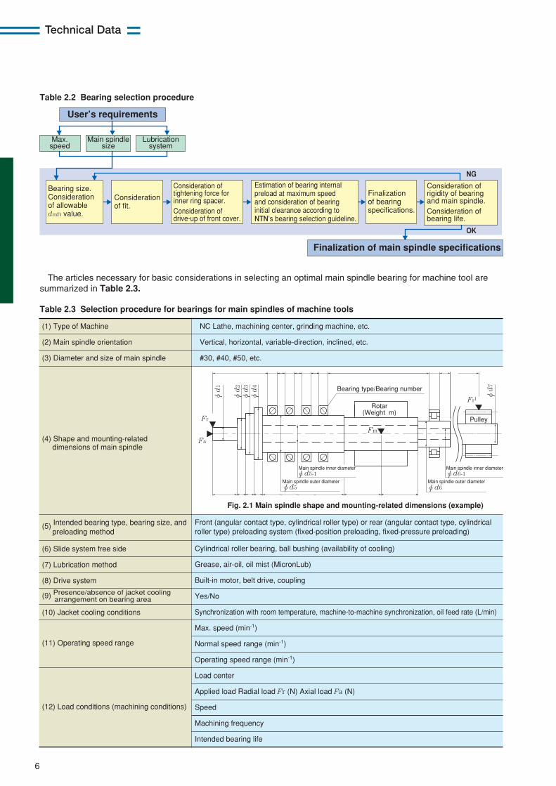
(4) Shape and mounting-related dimensions of main spindle
(6) Slide system free side
(7) Lubrication method
(8) Drive system
(10) Jacket cooling conditions
(5) Intended bearing type, bearing size, and preloading method
(9) Presence/absence of jacket cooling arrangement on bearing area
(11) Operating speed range
(12) Load conditions (machining conditions)
Cylindrical roller bearing, ball bushing (availability of cooling)
Grease, air-oil, oil mist (MicronLub)
Built-in motor, belt drive, coupling
Yes/No
Synchronization with room temperature, machine-to-machine synchronization, oil feed rate (L/min)
Max. speed (min-1)
Normal speed range (min-1)
Operating speed range (min-1)
Load center
Applied load Radial load Fr (N) Axial load Fa (N)
Speed
Machining frequency
Intended bearing life
Fig. 2.1 Main spindle shape and mounting-related dimensions (example)
φd5
φd5-1
Pulley
Rotar (Weight m)
Bearing type/Bearing number
Fa
Fr
Fr1
Fm
φd
1
φd
2
φd
3
φd6
φd6-1
φd
4
φd
7
Main spindle inner diameter
Main spindle inner diameter
Main spindle outer diameter
Main spindle outer diameter
Front (angular contact type, cylindrical roller type) or rear (angular contact type, cylindrical roller type) preloading system (fixed-position preloading, fixed-pressure preloading)
Table 2.3 Selection procedure for bearings for main spindles of machine tools
The articles necessary for basic considerations in selecting an optimal main spindle bearing for machine tool aresummarized in Table 2.3.
NG
OK
User’s requirements
Max. speed
Main spindle size
Lubrication system
Bearing size. Consideration of allowable dmn value.
Consideration of tightening force for inner ring spacer. Consideration of drive-up of front cover.
Estimation of bearing internal preload at maximum speed and consideration of bearing initial clearance according to NTN’s bearing selection guideline.
Finalization of bearing specifications.
Consideration of rigidity of bearing and main spindle. Consideration of bearing life.
Consideration of fit.
Finalization of main spindle specifications
Table 2.2 Bearing selection procedure
6
Technical Data
7
Technical Data
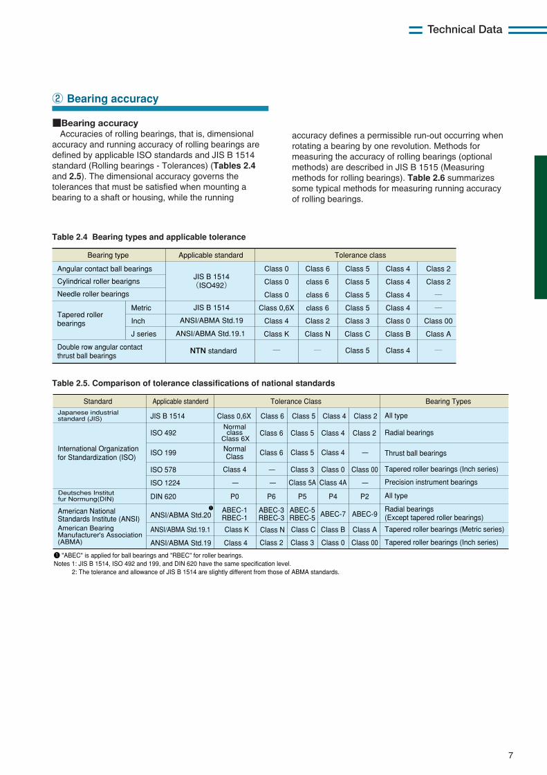
■Bearing accuracyAccuracies of rolling bearings, that is, dimensional
accuracy and running accuracy of rolling bearings aredefined by applicable ISO standards and JIS B 1514standard (Rolling bearings - Tolerances) (Tables 2.4and 2.5). The dimensional accuracy governs thetolerances that must be satisfied when mounting abearing to a shaft or housing, while the running
② Bearing accuracy
Table 2.4 Bearing types and applicable tolerance
Table 2.5. Comparison of tolerance classifications of national standards
accuracy defines a permissible run-out occurring whenrotating a bearing by one revolution. Methods formeasuring the accuracy of rolling bearings (optionalmethods) are described in JIS B 1515 (Measuringmethods for rolling bearings). Table 2.6 summarizessome typical methods for measuring running accuracyof rolling bearings.
Bearing type
Double row angular contact thrust ball bearings
Tapered roller bearings
Cylindrical roller bearigns
Angular contact ball bearings
Needle roller bearings
Applicable standard Tolerance class
Metric
Inch
J series
JIS B 1514 (ISO492)
JIS B 1514
ANSI/ABMA Std.19
ANSI/ABMA Std.19.1
NTN standard
Class 0
Class 0
Class 0
Class 0,6X
Class 4
Class K
―
Class 6
class 6
class 6
class 6
Class 2
Class N
Class 5
Class C
Class 3
Class 5
Class 5
Class 5
Class 5 Class 4
Class 4
Class 4
Class 4
Class 0
Class B
Class 4
Class A
Class 00
Class 2
Class 2
― ―
―
―
Standard Applicable standerdJapanese industrial standard (JIS)
Tolerance Class Bearing Types
Class 0,6X Class 6 Class 2
International Organization for Standardization (ISO)
Deutsches Institut fur Normung(DIN)
American National Standards Institute (ANSI)
Class 5 Class 4JIS B 1514
ISO 492
ISO 199
ISO 578
ISO 1224
DIN 620
ANSI/ABMA Std.20
ANSI/ABMA Std.19.1
ANSI/ABMA Std.19
Normalclass
Class 6XClass 6
Class 6
Class N
Class 2
NormalClass
Class 4
P0
ABEC-1RBEC-1
Class K
Class 4
Class 5 Class 4 Class 2
Class 5 Class 4
Class 3 Class 0 Class 00
Class 5A Class 4A
Class C Class B Class A
Class 3 Class 0 Class 00
ABEC-3RBEC-3
ABEC-5RBEC-5 ABEC-7 ABEC-9
P6 P5 P4 P2
ー
ー ー ー
ー
All type
Radial bearings
Thrust ball bearings
Tapered roller bearings (Inch series)
Precision instrument bearings
All type
Radial bearings (Except tapered roller bearings)
Tapered roller bearings (Metric series)
Tapered roller bearings (Inch series)
American Bearing Manufacturer's Association (ABMA)
1
1 "ABEC" is applied for ball bearings and "RBEC" for roller bearings. Notes 1: JIS B 1514, ISO 492 and 199, and DIN 620 have the same specification level.
2: The tolerance and allowance of JIS B 1514 are slightly different from those of ABMA standards.
8
Technical Data
To attain a higher level of running accuracy requiredof a main spindle of machine tool, a high-precisionbearing that satisfies the user's main spindlespecifications must be chosen. Usually, a high-precision bearing per JIS accuracy class 5, 4 or 2 isselected according to an intended application. Inparticular, the radial run-out, axial run-out and non-repetitive run-out of a main spindle bearing greatlyaffect the running accuracy of the main spindle andtherefore have to be strictly controlled. With the recentsuper high-precision machine tools, the control ofN.R.R.O. (Non-Repetitive Run-Out) has increasing
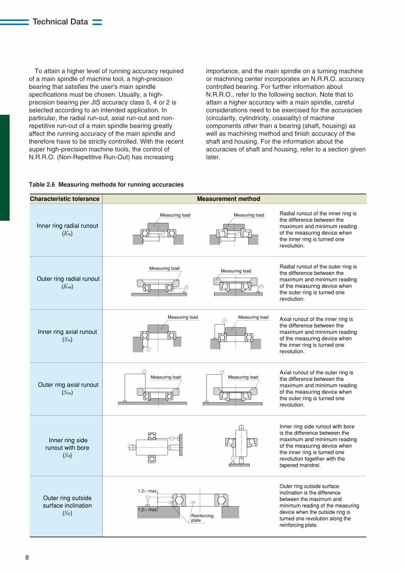
Table 2.6 Measuring methods for running accuracies
importance, and the main spindle on a turning machineor machining center incorporates an N.R.R.O. accuracycontrolled bearing. For further information aboutN.R.R.O., refer to the following section. Note that toattain a higher accuracy with a main spindle, carefulconsiderations need to be exercised for the accuracies(circularity, cylindricity, coaxiality) of machinecomponents other than a bearing (shaft, housing) aswell as machining method and finish accuracy of theshaft and housing. For the information about theaccuracies of shaft and housing, refer to a section givenlater.
Inner ring radial runout (Kia)
Outer ring radial runout (Kea)
Inner ring axial runout (Sia)
Outer ring axial runout (Sea)
Inner ring side runout with bore
(Sd)
Outer ring outside surface inclination
(SD)
Characteristic tolerance Measurement method
Measuring load Measuring load
Measuring loadMeasuring load
Measuring load Measuring load
Measuring loadMeasuring load
Reinforcing plate
1.2rs max
1.2rs max
Radial runout of the inner ring is the difference between the maximum and minimum reading of the measuring device when the inner ring is turned one revolution.
Radial runout of the outer ring is the difference between the maximum and minimum reading of the measuring device when the outer ring is turned one revolution.
Axial runout of the inner ring is the difference between the maximum and minimum reading of the measuring device when the inner ring is turned one revolution.
Axial runout of the outer ring is the difference between the maximum and minimum reading of the measuring device when the outer ring is turned one revolution.
Inner ring side runout with bore is the difference between the maximum and minimum reading of the measuring device when the inner ring is turned one revolution together with the tapered mandrel.
Outer ring outside surface inclination is the difference between the maximum and minimum reading of the measuring device when the outside ring is turned one revolution along the reinforcing plate.
9
Technical Data
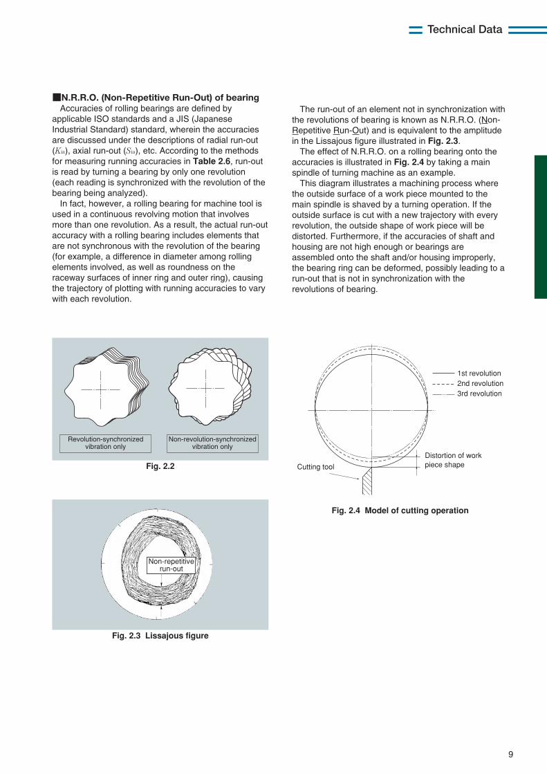
■N.R.R.O. (Non-Repetitive Run-Out) of bearingAccuracies of rolling bearings are defined by
applicable ISO standards and a JIS (JapaneseIndustrial Standard) standard, wherein the accuraciesare discussed under the descriptions of radial run-out(Kia), axial run-out (Sia), etc. According to the methodsfor measuring running accuracies in Table 2.6, run-outis read by turning a bearing by only one revolution(each reading is synchronized with the revolution of thebearing being analyzed).
In fact, however, a rolling bearing for machine tool isused in a continuous revolving motion that involvesmore than one revolution. As a result, the actual run-outaccuracy with a rolling bearing includes elements thatare not synchronous with the revolution of the bearing(for example, a difference in diameter among rollingelements involved, as well as roundness on theraceway surfaces of inner ring and outer ring), causingthe trajectory of plotting with running accuracies to varywith each revolution.
The run-out of an element not in synchronization withthe revolutions of bearing is known as N.R.R.O. (Non-Repetitive Run-Out) and is equivalent to the amplitudein the Lissajous figure illustrated in Fig. 2.3.
The effect of N.R.R.O. on a rolling bearing onto theaccuracies is illustrated in Fig. 2.4 by taking a mainspindle of turning machine as an example.
This diagram illustrates a machining process wherethe outside surface of a work piece mounted to themain spindle is shaved by a turning operation. If theoutside surface is cut with a new trajectory with everyrevolution, the outside shape of work piece will bedistorted. Furthermore, if the accuracies of shaft andhousing are not high enough or bearings areassembled onto the shaft and/or housing improperly,the bearing ring can be deformed, possibly leading to arun-out that is not in synchronization with therevolutions of bearing.
Revolution-synchronizedvibration only
Non-revolution-synchronizedvibration only
Fig. 2.2
Non-repetitive run-out
Fig. 2.3 Lissajous figure
Cutting tool
Distortion of work piece shape
1st revolution 2nd revolution 3rd revolution
Fig. 2.4 Model of cutting operation
10
Technical Data
Typical accuracy for spindle
AAB
tt1
t3 AB
t2 AB t
t4 A
B
da db
2
Accuracy
Deviation from circular form t
t1
t2
t3
t4
IT3
IT5
○
◎
Angularity
Run out
Eccent ricity
Symbol Tolerance3
P5 P4 P2
Fundamental permissible tolerance IT
→
IT32
IT32
IT3
IT4
IT22
IT22
IT2
IT3
IT02
IT02
IT32
IT22
4
4
1 The form tolerance, symbol, and reference face of spindle are in accordance with ISO R1101.
2 The length of the bearing fit surface is often too small to measure concentricity. Therefore, this criterion applies only when the fit surface has a width sufficient as a reference face.
3 When determining a tolerance for permissible form accuracy, the reference dimensions used are shaft diameters da and db. For example, when using a JIS class 5 bearing for a dia. 50 mm shaft, the tolerance of roundness is t = IT3/2 = 4/2=2 μm.
4 IT0 is preferred if the diameter tolerance of the bearing fit surface is IT3.
Table 2.7 Form accuracy of spindle 1
A
A
B
AB
AB AB
AB
t3 t3
t1
tt1
t4
tDa Db
2
Table 2.9 Fundamental tolerance IT
Classification of nominal dimension mm
Fundamental tolerance IT value μm
over incl.
6 10 18
30 50 80
120 180 250
315 400
10 18 30
50 80 120
180 250 315
400 500
0.6 0.8 1
1 1.2 1.5
2 3 4
5 6
1 1.2 1.5
1.5 2 2.5
3.5 4.5 6
7 8
1.5 2
2.5
2.5 3 4
5 7 8
9 10
2.5 3 4
4 5
6 8
10 12
13 15
4 5 6
7 8
10 12 14 16
18 20
IT0 IT1 IT2 IT3 IT4
Deviation from circular form
t
t1
t3
t4
IT3
IT5
○
◎
Run out
Angularity
Eccent ricity
P5 P4 P2
→
IT32
IT32
IT3
IT4
IT22
IT22
IT2
IT3
IT12
IT12
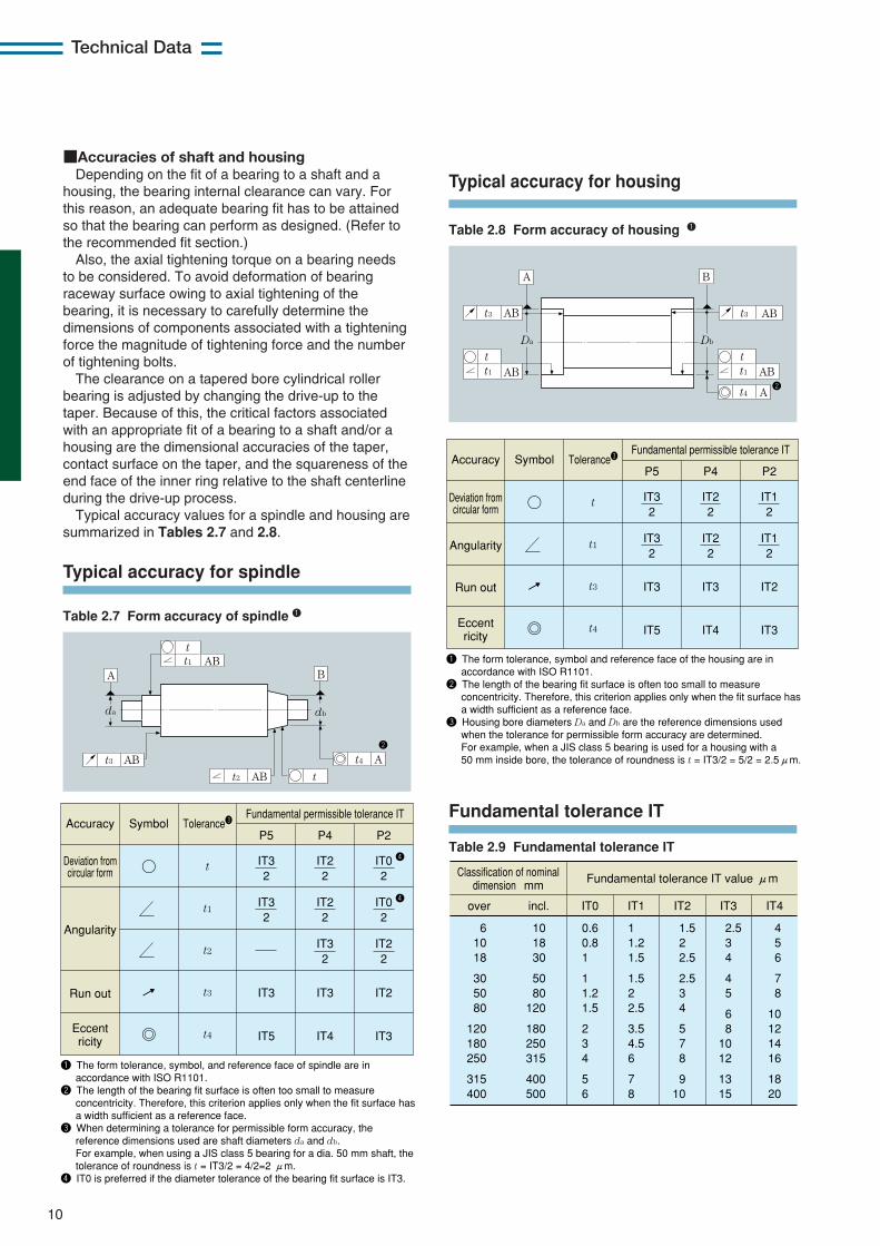
1 The form tolerance, symbol and reference face of the housing are in accordance with ISO R1101.
2 The length of the bearing fit surface is often too small to measure concentricity. Therefore, this criterion applies only when the fit surface has a width sufficient as a reference face.
3 Housing bore diameters Da and Db are the reference dimensions used when the tolerance for permissible form accuracy are determined. For example, when a JIS class 5 bearing is used for a housing with a 50 mm inside bore, the tolerance of roundness is t = IT3/2 = 5/2 = 2.5μm.
Accuracy Symbol Tolerance3Fundamental permissible tolerance IT
Typical accuracy for housing
Fundamental tolerance IT
Table 2.8 Form accuracy of housing 1
■Accuracies of shaft and housingDepending on the fit of a bearing to a shaft and a
housing, the bearing internal clearance can vary. Forthis reason, an adequate bearing fit has to be attainedso that the bearing can perform as designed. (Refer tothe recommended fit section.)
Also, the axial tightening torque on a bearing needsto be considered. To avoid deformation of bearingraceway surface owing to axial tightening of thebearing, it is necessary to carefully determine thedimensions of components associated with a tighteningforce the magnitude of tightening force and the numberof tightening bolts.
The clearance on a tapered bore cylindrical rollerbearing is adjusted by changing the drive-up to thetaper. Because of this, the critical factors associatedwith an appropriate fit of a bearing to a shaft and/or ahousing are the dimensional accuracies of the taper,contact surface on the taper, and the squareness of theend face of the inner ring relative to the shaft centerlineduring the drive-up process.
Typical accuracy values for a spindle and housing aresummarized in Tables 2.7 and 2.8.
11
Technical Data
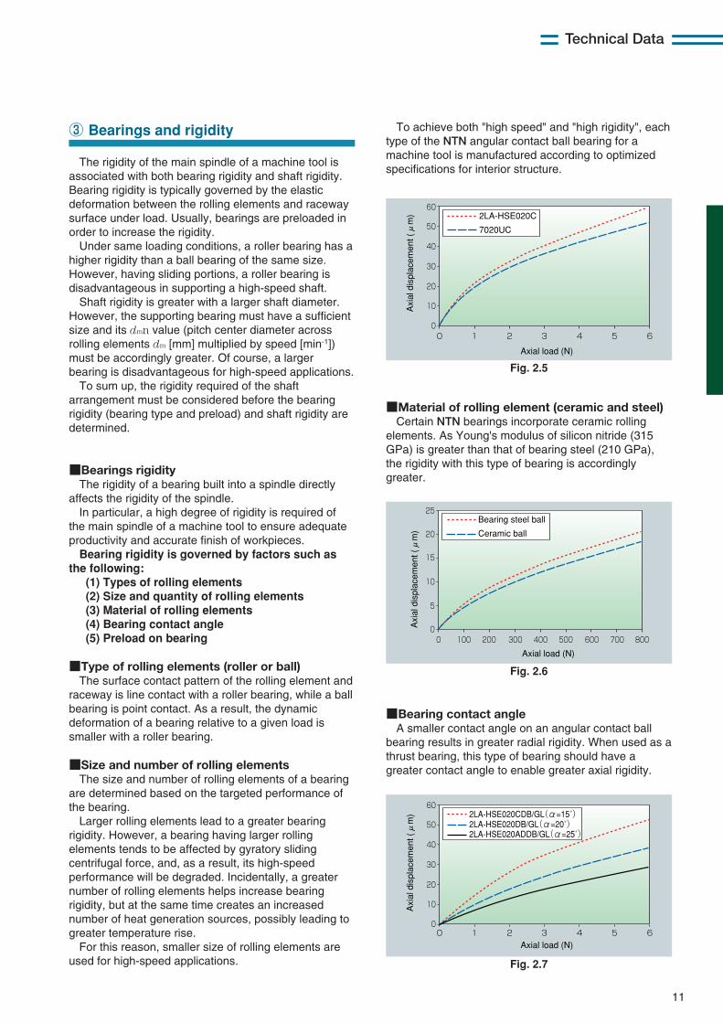
The rigidity of the main spindle of a machine tool isassociated with both bearing rigidity and shaft rigidity.Bearing rigidity is typically governed by the elasticdeformation between the rolling elements and racewaysurface under load. Usually, bearings are preloaded inorder to increase the rigidity.
Under same loading conditions, a roller bearing has ahigher rigidity than a ball bearing of the same size.However, having sliding portions, a roller bearing isdisadvantageous in supporting a high-speed shaft.
Shaft rigidity is greater with a larger shaft diameter.However, the supporting bearing must have a sufficientsize and its dmn value (pitch center diameter acrossrolling elements dm [mm] multiplied by speed [min-1])must be accordingly greater. Of course, a largerbearing is disadvantageous for high-speed applications.
To sum up, the rigidity required of the shaftarrangement must be considered before the bearingrigidity (bearing type and preload) and shaft rigidity aredetermined.
■Bearings rigidityThe rigidity of a bearing built into a spindle directly
affects the rigidity of the spindle.In particular, a high degree of rigidity is required of
the main spindle of a machine tool to ensure adequateproductivity and accurate finish of workpieces.Bearing rigidity is governed by factors such as
the following:(1) Types of rolling elements(2) Size and quantity of rolling elements(3) Material of rolling elements(4) Bearing contact angle(5) Preload on bearing
■Type of rolling elements (roller or ball)The surface contact pattern of the rolling element and
raceway is line contact with a roller bearing, while a ballbearing is point contact. As a result, the dynamicdeformation of a bearing relative to a given load issmaller with a roller bearing.
■Size and number of rolling elementsThe size and number of rolling elements of a bearing
are determined based on the targeted performance ofthe bearing.
Larger rolling elements lead to a greater bearingrigidity. However, a bearing having larger rollingelements tends to be affected by gyratory slidingcentrifugal force, and, as a result, its high-speedperformance will be degraded. Incidentally, a greaternumber of rolling elements helps increase bearingrigidity, but at the same time creates an increasednumber of heat generation sources, possibly leading togreater temperature rise.
For this reason, smaller size of rolling elements areused for high-speed applications.
③ Bearings and rigidity
50
60
40
30
20
10
010 2 3 4 5 6
Axial load (N)
Axi
al d
ispl
acem
ent (μ
m) 2LA-HSE020C
7020UC
Fig. 2.5
25
20
15
10
5
00 100 200 300 400 500 600 700 800
Axial load (N)
Axi
al d
ispl
acem
ent (μ
m)
Bearing steel ball
Ceramic ball
Fig. 2.6
50
60
40
30
20
10
010 2 3 4 5 6
Axial load (N)
Axi
al d
ispl
acem
ent (μ
m) 2LA-HSE020CDB/GL(α=15˚)
2LA-HSE020DB/GL(α=20˚) 2LA-HSE020ADDB/GL(α=25˚)
Fig. 2.7
■Material of rolling element (ceramic and steel)Certain NTN bearings incorporate ceramic rolling
elements. As Young's modulus of silicon nitride (315GPa) is greater than that of bearing steel (210 GPa),the rigidity with this type of bearing is accordinglygreater.
■Bearing contact angle A smaller contact angle on an angular contact ball
bearing results in greater radial rigidity. When used as athrust bearing, this type of bearing should have agreater contact angle to enable greater axial rigidity.
To achieve both "high speed" and "high rigidity", eachtype of the NTN angular contact ball bearing for amachine tool is manufactured according to optimizedspecifications for interior structure.
12
Technical Data
50
60
40
30
20
10
010 2 3 4 5 6
Axial load (kN)
Axi
al d
ispl
acem
ent (
µm) 2LA-HSE020DB/GL
2LA-HSE020DB/GN
2LA-HSE020DB/GM
Fig. 2.8
50
60
40
30
20
10
0
Axi
al d
ispl
acem
ent (
µm)
10 2 3 4 5 6
Axial load (kN)
2LA-HSE020DB/GL2LA-HSE020DBT/GL2LA-HSE020DTBT/GL
Fig. 2.9
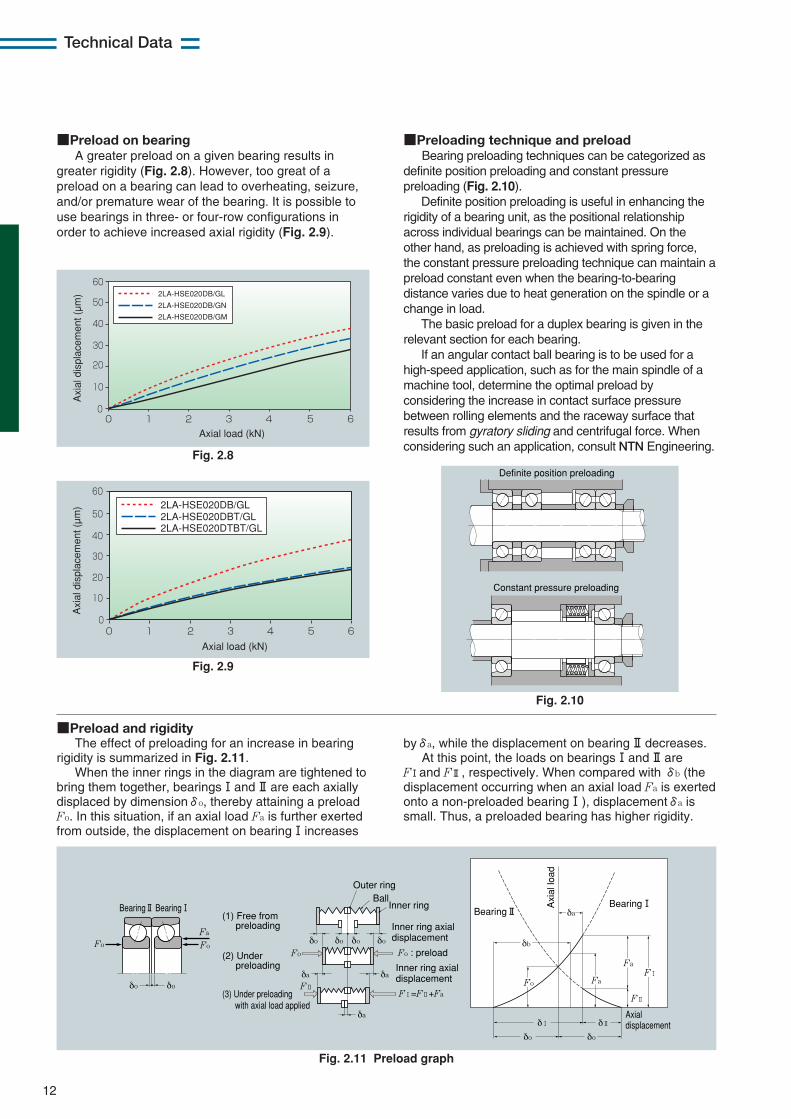
■Preload on bearingA greater preload on a given bearing results in
greater rigidity (Fig. 2.8). However, too great of apreload on a bearing can lead to overheating, seizure,and/or premature wear of the bearing. It is possible touse bearings in three- or four-row configurations inorder to achieve increased axial rigidity (Fig. 2.9).
■Preloading technique and preloadBearing preloading techniques can be categorized as
definite position preloading and constant pressurepreloading (Fig. 2.10).
Definite position preloading is useful in enhancing therigidity of a bearing unit, as the positional relationshipacross individual bearings can be maintained. On theother hand, as preloading is achieved with spring force,the constant pressure preloading technique can maintain apreload constant even when the bearing-to-bearingdistance varies due to heat generation on the spindle or achange in load.
The basic preload for a duplex bearing is given in therelevant section for each bearing.
If an angular contact ball bearing is to be used for ahigh-speed application, such as for the main spindle of amachine tool, determine the optimal preload byconsidering the increase in contact surface pressurebetween rolling elements and the raceway surface thatresults from gyratory sliding and centrifugal force. Whenconsidering such an application, consult NTN Engineering.
byδa, while the displacement on bearing!!decreases.At this point, the loads on bearings!and!!are
F!and F!!, respectively. When compared with δb (thedisplacement occurring when an axial load Fa is exertedonto a non-preloaded bearing!), displacementδa issmall. Thus, a preloaded bearing has higher rigidity.
Definite position preloading
Constant pressure preloading
Fig. 2.10
Fa
FoFo
δo δo
Inner ring axial displacement
Fo : preload Inner ring axial displacement
F1=F2+Fa
(1) Free from preloading
(2) Under preloading
(3) Under preloading with axial load applied
Fo
Bearing@ Bearing! Bearing@Bearing!
Axial displacement
δo
δ1 δ2
δo
Fo
Fa
FaF1
F2
Axi
al lo
ad
δb
δa
δoδoδoδo
F2
δa δa
δa
Outer ring
Inner ringBall
Fig. 2.11 Preload graph
■Preload and rigidityThe effect of preloading for an increase in bearing
rigidity is summarized in Fig. 2.11.When the inner rings in the diagram are tightened to
bring them together, bearings!and!!are each axiallydisplaced by dimensionδo, thereby attaining a preloadFo. In this situation, if an axial load Fa is further exertedfrom outside, the displacement on bearing!increases
13
Technical Data
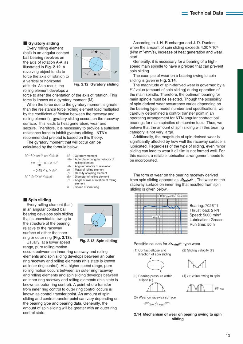
■ Gyratory slidingEvery rolling element
(ball) in an angular contactball bearing revolves onthe axis of rotation A-A' asillustrated in Fig. 2.12. Arevolving object tends toforce the axis of rotation toa vertical or horizontalattitude. As a result, therolling element develops aforce to alter the orientation of the axis of rotation. Thisforce is known as a gyratory moment (M).
When the force due to the gyratory moment is greaterthan the resistance force (rolling element load multipliedby the coefficient of friction between the raceway androlling element) , gyratory sliding occurs on the racewaysurface. This leads to heat generation, wear andseizure. Therefore, it is necessary to provide a sufficientresistance force to inhibit gyratory sliding. NTN'srecommended preload is based on this theory.
The gyratory moment that will occur can becalculated by the formula below.
■ Spin slidingEvery rolling element (ball)
in an angular contact ballbearing develops spin slidingthat is unavoidable owing tothe structure of the bearing,relative to the racewaysurface of either the innerring or outer ring (Fig. 2.13).
Usually, at a lower speedrange, pure rolling motionoccurs between an inner ring raceway and rollingelements and spin sliding develops between an outerring raceway and rolling elements (this state is knownas inner ring control). At a higher speed range, purerolling motion occurs between an outer ring racewayand rolling elements and spin sliding develops betweenan inner ring raceway and rolling elements (this state isknown as outer ring control). A point where transferfrom inner ring control to outer ring control occurs isknown as control transfer point. An amount of spinsliding and control transfer point can vary depending onthe bearing type and bearing data. Generally, theamount of spin sliding will be greater with an outer ringcontrol state.
Fig. 2.12 Gyratory sliding
M=k×ωb×ωc×sinβ
M∝dw5×n2×sinβ
k= 101
×m×dw2
=0.45×ρ×dw5
M :Gyratory moment ωb:Autorotation angular velocity of rolling element ωc:Angular velocity of revolution m :Mass of rolling element ρ :Density of rolling element dw:Diameter of rolling element β :Angle of axis of rotation of rolling element n :Speed of inner ring
A
A'
M
M
Fig. 2.13 Spin sliding
2.14 Mechanism of wear on bearing owing to spinsliding
According to J. H. Rumbarger and J. D. Dunfee,when the amount of spin sliding exceeds 4.20×10⁶
(N/m m2-mm/s), increase of heat generation and wearstart.
Generally, it is necessary for a bearing of a high-speed main spindle to have a preload that can preventspin sliding.
The example of wear on a bearing owing to spinsliding is given in Fig. 2.14.
The magnitude of spin-derived wear is governed by aPV value (amount of spin sliding) during operation ofthe main spindle. Therefore, the optimum bearing formain spindle must be selected. Though the possibilityof spin-derived wear occurrence varies depending onthe bearing type, model number and specifications, wecarefully determined a control transfer point in anoperating arrangement for NTN angular contract ballbearings for main spindles of machine tools. Thus, webelieve that the amount of spin sliding with this bearingcategory is not very large.
Additionally, the magnitude of spin-derived wear issignificantly affected by how well the raceway surface islubricated. Regardless of the type of sliding, even minorsliding can lead to wear if oil film is not formed well. Forthis reason, a reliable lubrication arrangement needs tobe incorporated.
2.5μm
Rolling contact area
Bearing: 7026T1 Thrust load: 2 kN Speed: 5000 min-1 Lubrication: Grease Run time: 50 h
PV max
(5) Wear on raceway surface
The form of wear on the bearing raceway derived from spin sliding appears as . The wear on the raceway surface on inner ring that resulted from spin sliding is given below.
Possible causes for type wear
(1) Contact ellipse and direction of spin sliding
(3) Bearing pressure within ellipse (P)
(2) Sliding velocity (V)
(4) PV value owing to spin
14
Technical Data
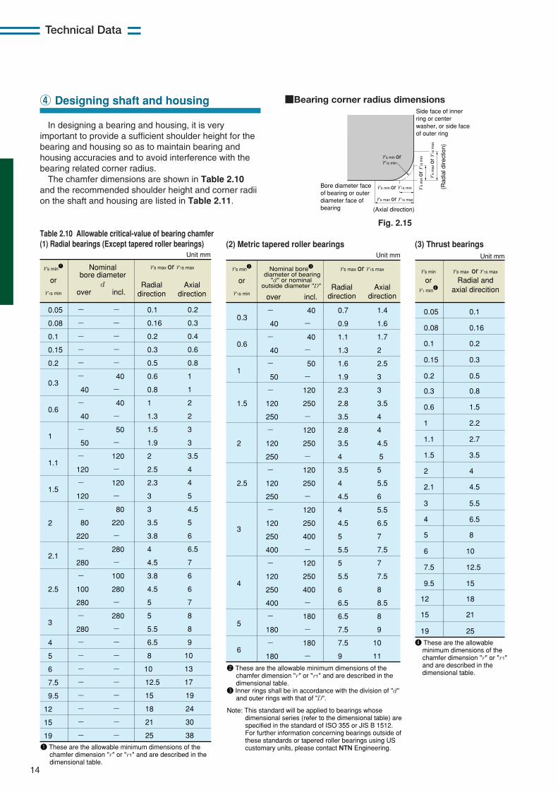
In designing a bearing and housing, it is veryimportant to provide a sufficient shoulder height for thebearing and housing so as to maintain bearing andhousing accuracies and to avoid interference with thebearing related corner radius.
The chamfer dimensions are shown in Table 2.10and the recommended shoulder height and corner radiion the shaft and housing are listed in Table 2.11.
④ Designing shaft and housing
Table 2.10 Allowable critical-value of bearing chamfer(1) Radial bearings (Except tapered roller bearings) (2) Metric tapered roller bearings
0.05
0.08
0.1
0.15
0.2
0.3
0.6
1
1.1
1.5
2.1
3
2.5
4
5
6
7.5
9.5
12
15
19
2
-
-
-
-
-
-
40
-
40
-
50
-
120
-
120
-
80
220
-
280
-
100
280
-
280
-
-
-
-
-
-
-
-
-
-
-
-
-
40
-
40
-
50
-
120
-
120
-
80
220
-
280
-
100
280
-
280
-
-
-
-
-
-
-
-
-
0.1
0.16
0.2
0.3
0.5
0.6
0.8
1
1.3
1.5
1.9
2
2.5
2.3
3
3
3.5
3.8
4
4.5
3.8
4.5
5
5
5.5
6.5
8
10
12.5
15
18
21
25
0.2
0.3
0.4
0.6
0.8
1
1
2
2
3
3
3.5
4
4
5
4.5
5
6
6.5
7
6
6
7
8
8
9
10
13
17
19
24
30
38
Unit mm
rs min1
or
r1s min
Nominal bore diameter
d over incl.
rs max or r1s max
Radial
directionAxial
direction
1 These are the allowable minimum dimensions of the chamfer dimension "r" or "r1" and are described in the dimensional table.
0.3
0.6
1
5
3
-
40
-
40
-
50
-
120
250
-
120
250
-
120
250
-
120
250
400
-
120
250
400
-
180
-
180
40
-
40
-
50
-
120
250
-
120
250
-
120
250
-
120
250
400
-
120
250
400
-
180
-
180
-
0.7
0.9
1.1
1.3
1.6
1.9
2.3
2.8
3.5
2.8
3.5
4
3.5
4
4.5
4
4.5
5
5.5
5
5.5
6
6.5
6.5
7.5
7.5
9
1.4
1.6
1.7
2
2.5
3
3
3.5
4
4
4.5
5
5
5.5
6
5.5
6.5
7
7.5
7
7.5
8
8.5
8
9
10
11
1.5
2
2.5
4
6
Unit mm
rs min2
or
r1s min
rs max or r1s max
Radial
directionAxial
direction
Nominal bore3 diameter of bearing
"d" or nominal outside diameter "D"
over incl.
2 These are the allowable minimum dimensions of the chamfer dimension "r" or "r1" and are described in the dimensional table. 3 Inner rings shall be in accordance with the division of "d" and outer rings with that of "D". Note: This standard will be applied to bearings whose dimensional series (refer to the dimensional table) are specified in the standard of ISO 355 or JIS B 1512. For further information concerning bearings outside of these standards or tapered roller bearings using US customary units, please contact NTN Engineering.
(3) Thrust bearings
0.05
0.08
0.1
0.15
0.2
0.3
0.6
1
1.1
1.5
2
2.1
4
3
5
6
7.5
9.5
19
12
15
0.1
0.16
0.2
0.3
0.5
0.8
1.5
2.2
2.7
3.5
4
4.5
5.5
6.5
21
15
25
10
8
12.5
18
4 These are the allowable minimum dimensions of the chamfer dimension "r" or "r1" and are described in the dimensional table.
rs max or r1s max
Radial and axial direcition
rs min
or r1 min
4
Unit mm
Side face of inner ring or center washer, or side face of outer ring
Bore diameter face of bearing or outer diameter face of bearing (Axial direction)
rs min or r1s min (Rad
ial d
irect
ion)
rs max or r1s max
rs m
in o
r r1
s m
in
rs m
ax o
r r1
s m
ax
rs min or r1s min
Fig. 2.15
■Bearing corner radius dimensions
15
Technical Data
Table 2.11 Fillet radius and abutment height
rs min ras max
0.050.080.1 0.150.2 0.3 0.6 1 1 1.5 2 2 2 2.5 3 4 5 6 8
10 12 15
0.050.080.1 0.150.2 0.3 0.6 1 1.1 1.5 2 2.1 2.5 3 4 5 6 7.5 9.5
12 15 19
0.3 0.3 0.4 0.6 0.8 1.252.252.753.5 4.255 6 6 7 9
11 14 18 22 27 32 42
Normal use1
Unit mm
1 If bearing supports large axial load, the height of the shoulder must exceed the value given here.
Note: ras max maximum allowable fillet radius.
h (min)
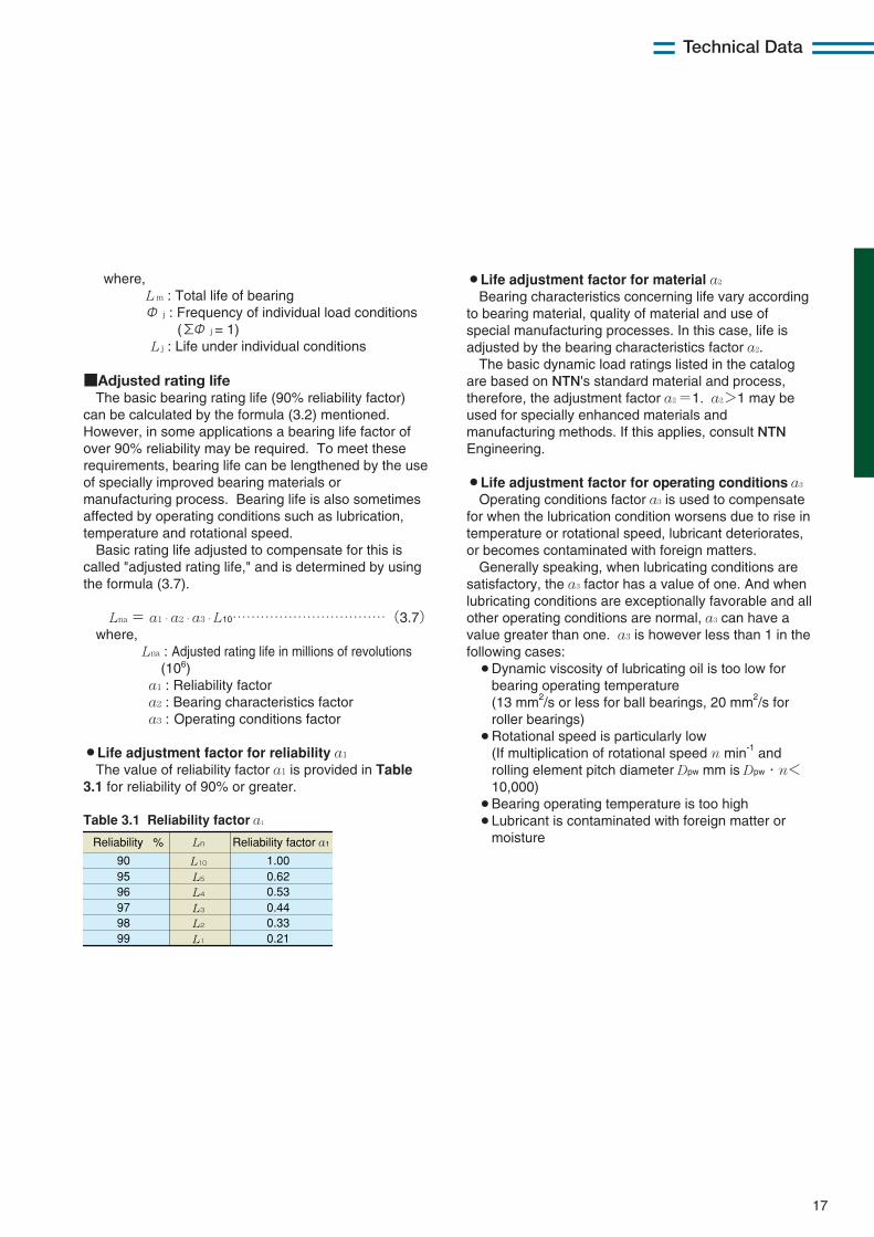
2.12 Relief dimensions for grounding
1
1.1
1.5
2
2.1
2.5
3
4
5
6
7.5
2
2.4
3.2
4
4
4
4.7
5.9
7.4
8.6
10
rs min
0.2
0.3
0.4
0.5
0.5
0.5
0.5
0.5
0.6
0.6
0.6
1.3
1.5
2
2.5
2.5
2.5
3
4
5
6
7
b t rcRelief dimensions
rs min
rs min
rs min
rs min
ra h
hra
rs min
rs min
rc
rc
b
b
t
t
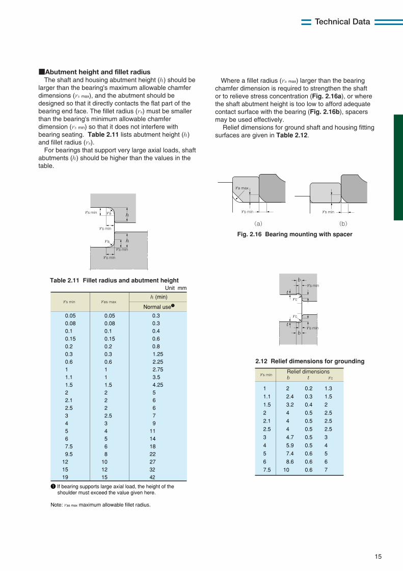
■Abutment height and fillet radiusThe shaft and housing abutment height (h) should be
larger than the bearing's maximum allowable chamferdimensions (rs max), and the abutment should bedesigned so that it directly contacts the flat part of thebearing end face. The fillet radius (ra) must be smallerthan the bearing's minimum allowable chamferdimension (rs min) so that it does not interfere withbearing seating. Table 2.11 lists abutment height (h)and fillet radius (ra).
For bearings that support very large axial loads, shaftabutments (h) should be higher than the values in thetable.
rs min
ra max
rs min
(a) (b)
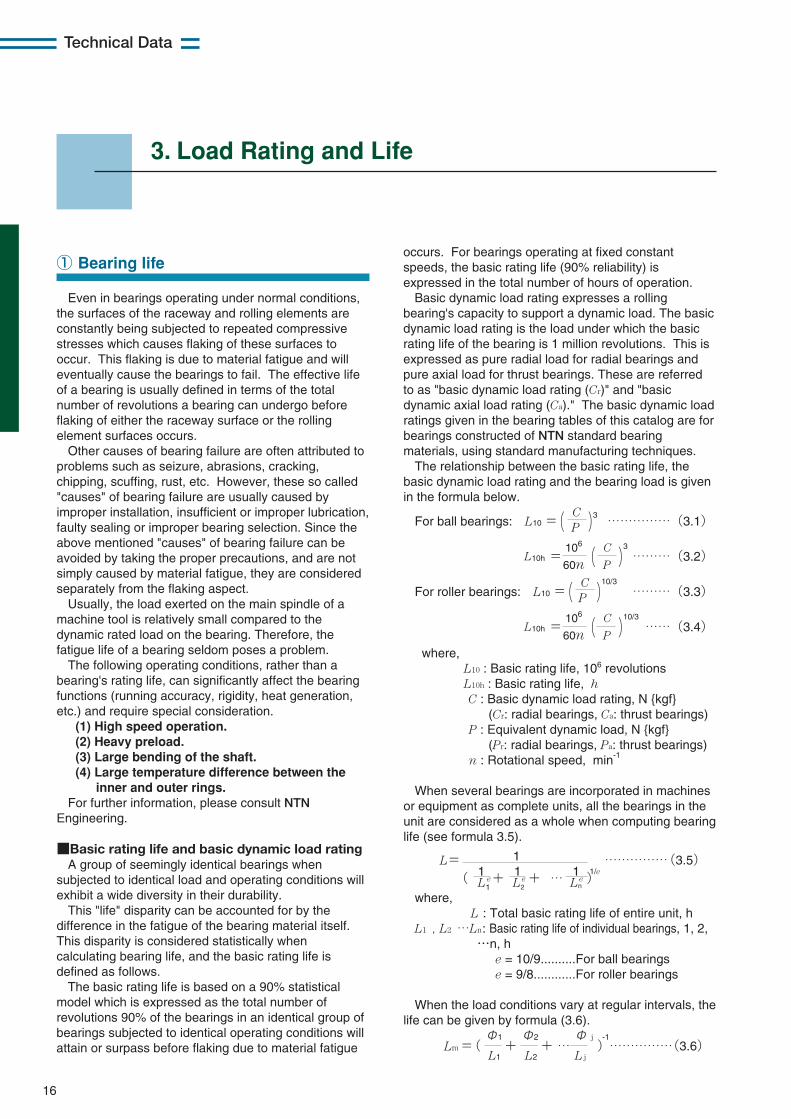
Fig. 2.16 Bearing mounting with spacer
Where a fillet radius (ra max) larger than the bearingchamfer dimension is required to strengthen the shaftor to relieve stress concentration (Fig. 2.16a), or wherethe shaft abutment height is too low to afford adequatecontact surface with the bearing (Fig. 2.16b), spacersmay be used effectively.
Relief dimensions for ground shaft and housing fittingsurfaces are given in Table 2.12.
16
Technical Data
3. Load Rating and Life
Even in bearings operating under normal conditions,the surfaces of the raceway and rolling elements areconstantly being subjected to repeated compressivestresses which causes flaking of these surfaces tooccur. This flaking is due to material fatigue and willeventually cause the bearings to fail. The effective lifeof a bearing is usually defined in terms of the totalnumber of revolutions a bearing can undergo beforeflaking of either the raceway surface or the rollingelement surfaces occurs.
Other causes of bearing failure are often attributed toproblems such as seizure, abrasions, cracking,chipping, scuffing, rust, etc. However, these so called"causes" of bearing failure are usually caused byimproper installation, insufficient or improper lubrication,faulty sealing or improper bearing selection. Since theabove mentioned "causes" of bearing failure can beavoided by taking the proper precautions, and are notsimply caused by material fatigue, they are consideredseparately from the flaking aspect.
Usually, the load exerted on the main spindle of amachine tool is relatively small compared to thedynamic rated load on the bearing. Therefore, thefatigue life of a bearing seldom poses a problem.
The following operating conditions, rather than abearing's rating life, can significantly affect the bearingfunctions (running accuracy, rigidity, heat generation,etc.) and require special consideration.
(1) High speed operation.(2) Heavy preload.(3) Large bending of the shaft.(4) Large temperature difference between the
inner and outer rings.For further information, please consult NTN
Engineering.
■Basic rating life and basic dynamic load ratingA group of seemingly identical bearings when
subjected to identical load and operating conditions willexhibit a wide diversity in their durability.
This "life" disparity can be accounted for by thedifference in the fatigue of the bearing material itself.This disparity is considered statistically whencalculating bearing life, and the basic rating life isdefined as follows.
The basic rating life is based on a 90% statisticalmodel which is expressed as the total number ofrevolutions 90% of the bearings in an identical group ofbearings subjected to identical operating conditions willattain or surpass before flaking due to material fatigue
occurs. For bearings operating at fixed constantspeeds, the basic rating life (90% reliability) isexpressed in the total number of hours of operation.
Basic dynamic load rating expresses a rollingbearing's capacity to support a dynamic load. The basicdynamic load rating is the load under which the basicrating life of the bearing is 1 million revolutions. This isexpressed as pure radial load for radial bearings andpure axial load for thrust bearings. These are referredto as "basic dynamic load rating (Cr)" and "basicdynamic axial load rating (Ca)." The basic dynamic loadratings given in the bearing tables of this catalog are forbearings constructed of NTN standard bearingmaterials, using standard manufacturing techniques.
The relationship between the basic rating life, thebasic dynamic load rating and the bearing load is givenin the formula below.
For ball bearings: L10 =(C
)3……………(3.1)P
L10h =106
(C
)3
………(3.2)60n P
For roller bearings: L10 =(C
)10/3
………(3.3)P
L10h =106
(C
)10/3
……(3.4)60n P
where,L10 : Basic rating life, 106 revolutionsL10h : Basic rating life, hC : Basic dynamic load rating, N {kgf}
(Cr: radial bearings, Ca: thrust bearings)P : Equivalent dynamic load, N {kgf}
(Pr: radial bearings, Pa: thrust bearings)n : Rotational speed, min-1
When several bearings are incorporated in machinesor equipment as complete units, all the bearings in theunit are considered as a whole when computing bearinglife (see formula 3.5).
1L=( 1 + 1 + … 1 )
1/e……………(3.5)
L1e L2
e Lne
where,L : Total basic rating life of entire unit, h
L1 , L2 …Ln: Basic rating life of individual bearings, 1, 2,…n, h
e = 10/9..........For ball bearingse = 9/8............For roller bearings
When the load conditions vary at regular intervals, thelife can be given by formula (3.6).
Lm =( Φ1
+Φ2
+ …Φ j
)-1……………(3.6)
L1 L2 L j
① Bearing life
17
Technical Data
where,L m : Total life of bearingΦ j : Frequency of individual load conditions
(ΣΦ j = 1)L j : Life under individual conditions
■Adjusted rating lifeThe basic bearing rating life (90% reliability factor)
can be calculated by the formula (3.2) mentioned.However, in some applications a bearing life factor ofover 90% reliability may be required. To meet theserequirements, bearing life can be lengthened by the useof specially improved bearing materials ormanufacturing process. Bearing life is also sometimesaffected by operating conditions such as lubrication,temperature and rotational speed.
Basic rating life adjusted to compensate for this iscalled "adjusted rating life," and is determined by usingthe formula (3.7).
Lna = a1・a2・a3・L10……………………………(3.7)where,
Lna : Adjusted rating life in millions of revolutions(106)
a1 : Reliability factora2 : Bearing characteristics factora3 : Operating conditions factor
¡Life adjustment factor for reliability a1
The value of reliability factor a1 is provided in Table3.1 for reliability of 90% or greater.
¡Life adjustment factor for material a2
Bearing characteristics concerning life vary accordingto bearing material, quality of material and use ofspecial manufacturing processes. In this case, life isadjusted by the bearing characteristics factor a2.
The basic dynamic load ratings listed in the catalogare based on NTN's standard material and process,therefore, the adjustment factor a2 =1. a2>1 may beused for specially enhanced materials andmanufacturing methods. If this applies, consult NTNEngineering.
¡Life adjustment factor for operating conditions a3
Operating conditions factor a3 is used to compensatefor when the lubrication condition worsens due to rise intemperature or rotational speed, lubricant deteriorates,or becomes contaminated with foreign matters.
Generally speaking, when lubricating conditions aresatisfactory, the a3 factor has a value of one. And whenlubricating conditions are exceptionally favorable and allother operating conditions are normal, a3 can have avalue greater than one. a3 is however less than 1 in thefollowing cases:¡Dynamic viscosity of lubricating oil is too low for
bearing operating temperature(13 mm2/s or less for ball bearings, 20 mm2/s forroller bearings)
¡Rotational speed is particularly low(If multiplication of rotational speed n min-1 androlling element pitch diameter Dpw mm is Dpw・n<10,000)
¡Bearing operating temperature is too high¡Lubricant is contaminated with foreign matter or
moistureTable 3.1 Reliability factor a1
Ln
909596979899
L10
L5
L4
L3
L2
L1
1.000.620.530.440.330.21
Reliability % Reliability factor a1
18
Technical Data
■New bearing life formulaBy dramatic improvement in bearing materials and
bearing manufacturing techniques, bearings can offer alife several times as long as that calculated from theformula (3.7) as long as they are mounted with minimalmounting errors are fully free from foreign matter andadequately lubricated. This finding was obtained by aseries of experiments performed by NTN. NTN's newbearing life calculation theory is based on a fatigue limittheory according to which under clean and efficientlubrication conditions, bearing life can be indefinite at aparticular contact surface pressure. For this purpose,NTN performs calculations based on the contactsurface pressure at a fatigue limit of 1.5 GPa that isdefined in ISO281: 1990/Amd2: 2000. Incidentally, ifforeign matter enters into a bearing, depending on thesize and amount of foreign matter, the actual life of thatbearing can be much shorter than the rating life that iscalculated by formula (3.7). Also, poor lubricatingconditions can cause the actual bearing life to beshorter than the rating life. NTN's new bearing lifecalculation is designed to determine a new lifecorrection factor aNTN by the following formula.
C pLnm=a1・aNTN・(——)……………………(3.8)
P
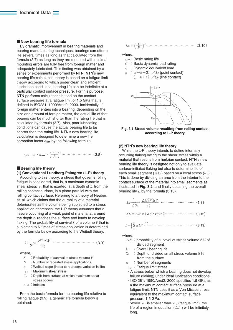
■Bearing life theory(1) Conventional Lundberg-Palmgren (L-P) theory
According to this theory, a stress that governs rollingfatigue is considered, that is, a maximum dynamicshear stress τo that is exerted, at a depth of Zo from therolling contact surface, in a plane parallel with therolling contact surface. Referring to a theory of Neuber,et. al. which claims that the durability of a materialdeteriorates as the volume being subjected to a stressapplication decreases, the L-P theory assumes that afissure occurring at a weak point of material at aroundthe depth Zo reaches the surface and leads to developflaking. The probability of survival S of a volume V that issubjected to N times of stress application is determinedby the formula below according to the Weibull theory.
1 N eτc0VRn —∝———— ……………………………(3.9)
S zh0
where,S :Probability of survival of stress volume V
N :Number of repeated stress applicationse :Weibull slope (index to represent variation in life)τo :Maximum shear stressZo :Depth from surface at which maximum shear
stress occursc,h:Indexes
From the basic formula for the bearing life relative torolling fatigue (3.9), a generic life formula below isobtained:
C pL10=(——)…………………………………(3.10)
P
where,L10:Basic rating lifeC :Basic dynamic load ratingP :Dynamic equivalent loadp :(c−h+2)/3e (point contact)
(c−h+1)/2e (line contact)
Fig. 3.1 Stress volume resulting from rolling contactaccording to L-P theory
2a
Z0
τ0
(2) NTN's new bearing life theoryWhile the L-P theory intends to define internally
occurring flaking owing to the shear stress within amaterial that results from hertzian contact, NTN's newbearing life theory is designed not only to evaluatesurface-initiated flaking but also to determine life ofeach small segment (ΔL1) based on a local stress (σ1).This is done by dividing an area from the interior to thecontact surface of the material into small segments asillustrated in Fig. 3.2, and finally obtaining the overallbearing life L by the formula (3.13).
1 ΔN eiσ
ciΔViRn ———∝—————— …………………………(3.11)
ΔSi zhi
ΔLi=ΔNi∝(σ-ci ΔV -1
i z hi )
1/e ……………………(3.12)
n -1/e
L={ΣΔLi-e }……………………………………(3.13)
i=1
where,ΔSi:probability of survival of stress volumeΔVi of
divided segmentL :Overall bearing lifeZi :Depth of divided small stress volumeΔVi
from the surfacen :Number of segmentsσu :Fatigue limit stress・A stress below which a bearing does not develop
failure (flaking) under ideal lubrication conditions.・ISO 281: 1990/Amd2: 2000 specifies 1.5 GPa as
a the maximum contact surface pressure at afatigue limit. NTN uses it as a Von Misses stressequivalent to the maximum contact surfacepressure 1.5 GPa.
・When σi is smaller than σu (fatigue limit), thelife of a region in question (ΔL1) will be infinitelylong.

19
Technical Data
■NTN's new bearing life formulaThe correlation between the NTN's life correction
factor aNTN and corrected rating life Lnm is defined by theformula (3.14) below.
C pLnm=a1・aNTN・(——)…………………………(3.14)
P
where,Lnm :Corrected rating lifea1 :Reliability coefficientaNTN:Life correction factor that reflects material
properties, fatigue limit stress, contamination with foreign matter and oil film parameter (Λ) (0.1 ≦aNTN≦50)
C :Basic dynamic load ratingP :Dynamic equivalent loadp :Index 3 (ball bearing) 10/3 (roller bearing)
(1) Effect of fatigue limitNTN's new bearing life formula introduces a concept
of fatigue life according to which the bearing life isinfinitely long at a particular contact surface pressure asillustrated in Fig. 3.3 assuming no foreign matter istrapped in the bearing and the bearing is reliablylubricated.
(3) Effect of oil film parameter (Λ)The oil film parameter can be used to calculate
bearing life. The oil film parameter, designated byΛ, isthe ratio of the oil film thickness to the roughness of thesurface. It can be used to calculate the average stressacross the surface layer of two contacting surfaces,such as a rolling element and raceway. From thissurface layer stress, the contact surface pressure canbe determined. Bearing life is then calculated from thecontact surface pressure.
Conditions of two objects on surface layerCalculation model
Z
Pmax
y
Fig. 3.2 Calculation model
Fig. 3.3 Basic concept of fatigue limit
Fig. 3.4 Contact surface pressure distribution resultingfrom dent
(2) Effect of foreign matterThe effect of foreign matter is treated as surface-
initiated flaking that starts from a dent resulting fromtrapped foreign matter. NTN performs a bearing lifecalculation, assuming that the size of foreign matter andthe stress concentration area in the middle portion (thesize of this area corresponds with that of the foreignmatter) in the surface layer as well as the amount offoreign matter significantly affect the bearing life.
Life
Contact surface pressure equivalent to fatigue limit
Con
tact
str
ess
Rating life
Life reflecting fatigue limit
Dented raceway
Normal raceway
Smooth surface
Oil film
Object having composite roughness
of two objects
Fig. 3.5 Model of stress load onto the surface layer
Table 3.2 Status of contamination
Condition of contamination
Contamination coefficient
NAS class
Guideline for application
ISO cleanliness code (ISO 4406)
Extremely clean Clean Normal Lightly contaminated
Moderately contaminated
Highly contaminated
Severely contaminated
1 0.8 0.5 0.4 0.3 0.2 0.1
Filtered No filter
Less than 10 µm 10~30μm 30~50μm 50~70μm 70~100μm
13/10 15/12 17/14 19/16 21/18 23/20 25/22
0 3 6 8 9 10 12
100 µm or more
Ingress of much dust
■New life calculation formula chartVarious statuses of contamination with foreign matter
are defined in Table 3.2. The values of ISO codes andNAS classes are those for ball bearings that aresubjected to more severe operating conditions.
Extremely clean
Clean
Normal
Lightly contaminated
Moderately contaminated
Highly contaminated
Severely contaminated
0.010.01
1
10
100
0.1
0.1 1
50
15
1.9
0.5aN
TN
P/C
Extremely cleanCleanNormal
Severely contaminated
0.01
1
10
100
0.1
0.1 1
5035
16
1.32.5
aN
TN
P/C
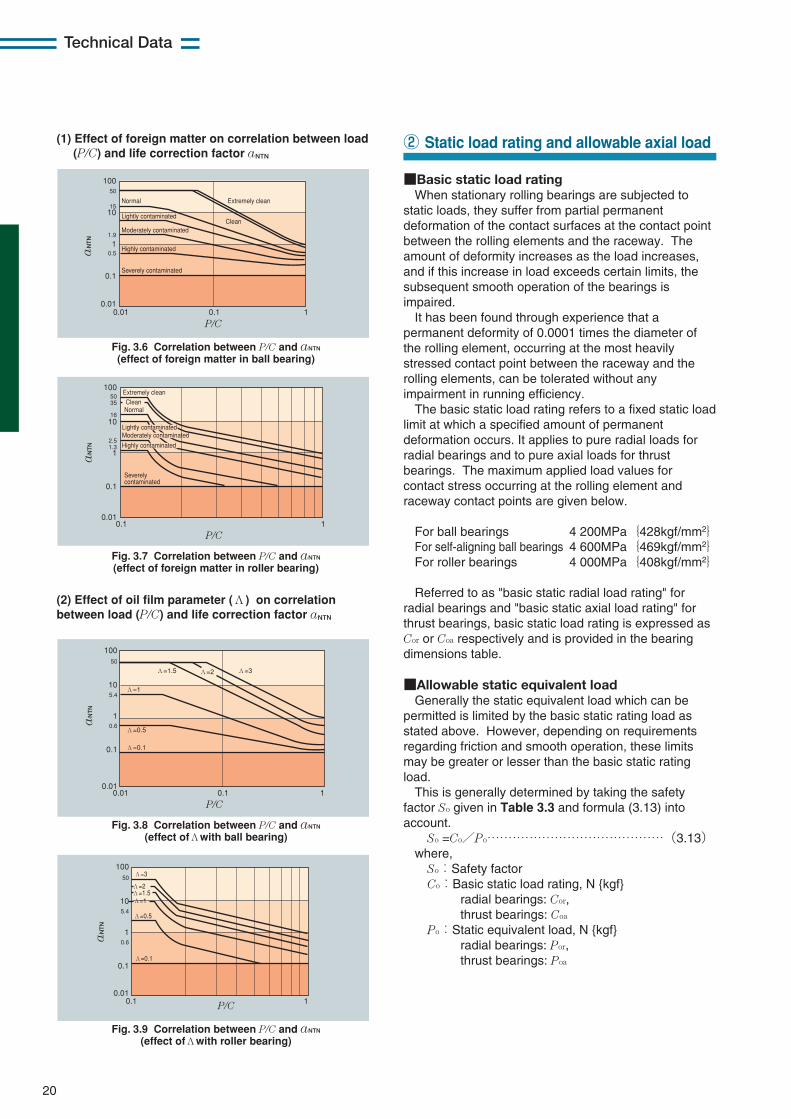
Fig. 3.6 Correlation between P/C and aNTN (effect of foreign matter in ball bearing)
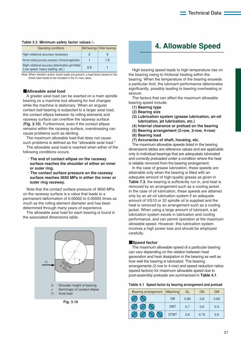
Fig. 3.8 Correlation between P/C and aNTN (effect ofΛwith ball bearing)
Fig. 3.9 Correlation between P/C and aNTN (effect ofΛwith roller bearing)
Fig. 3.7 Correlation between P/C and aNTN (effect of foreign matter in roller bearing)
0.01
1
10
100
0.1
0.01 0.1 1
50
0.6
5.4
aN
TN
P/C
Λ=3Λ=2Λ=1.5
Λ=1
Λ=0.5
Λ=0.1
0.01
1
10
100
0.1
0.1 1
50
0.6
5.4
aN
TN
P/C
Λ=3
Λ=1.5Λ=2
Λ=1
Λ=0.5
Λ=0.1
Lightly contaminatedModerately contaminated
Highly contaminated
20
Technical Data
■Basic static load ratingWhen stationary rolling bearings are subjected to
static loads, they suffer from partial permanentdeformation of the contact surfaces at the contact pointbetween the rolling elements and the raceway. Theamount of deformity increases as the load increases,and if this increase in load exceeds certain limits, thesubsequent smooth operation of the bearings isimpaired.
It has been found through experience that apermanent deformity of 0.0001 times the diameter ofthe rolling element, occurring at the most heavilystressed contact point between the raceway and therolling elements, can be tolerated without anyimpairment in running efficiency.
The basic static load rating refers to a fixed static loadlimit at which a specified amount of permanentdeformation occurs. It applies to pure radial loads forradial bearings and to pure axial loads for thrustbearings. The maximum applied load values forcontact stress occurring at the rolling element andraceway contact points are given below.
For ball bearings 4 200MPa{428kgf/mm2}For self-aligning ball bearings 4 600MPa{469kgf/mm2}For roller bearings 4 000MPa{408kgf/mm2}
Referred to as "basic static radial load rating" forradial bearings and "basic static axial load rating" forthrust bearings, basic static load rating is expressed asCor or Coa respectively and is provided in the bearingdimensions table.
■Allowable static equivalent loadGenerally the static equivalent load which can be
permitted is limited by the basic static rating load asstated above. However, depending on requirementsregarding friction and smooth operation, these limitsmay be greater or lesser than the basic static ratingload.
This is generally determined by taking the safetyfactor So given in Table 3.3 and formula (3.13) intoaccount.
So =Co/Po……………………………………(3.13)where,
So:Safety factorCo:Basic static load rating, N {kgf}
radial bearings: Cor,thrust bearings: Coa
Po:Static equivalent load, N {kgf}radial bearings: Por,thrust bearings: Poa
② Static load rating and allowable axial load(1) Effect of foreign matter on correlation between load(P/C) and life correction factor aNTN
(2) Effect of oil film parameter (Λ) on correlationbetween load (P/C) and life correction factor aNTN
21
Technical Data
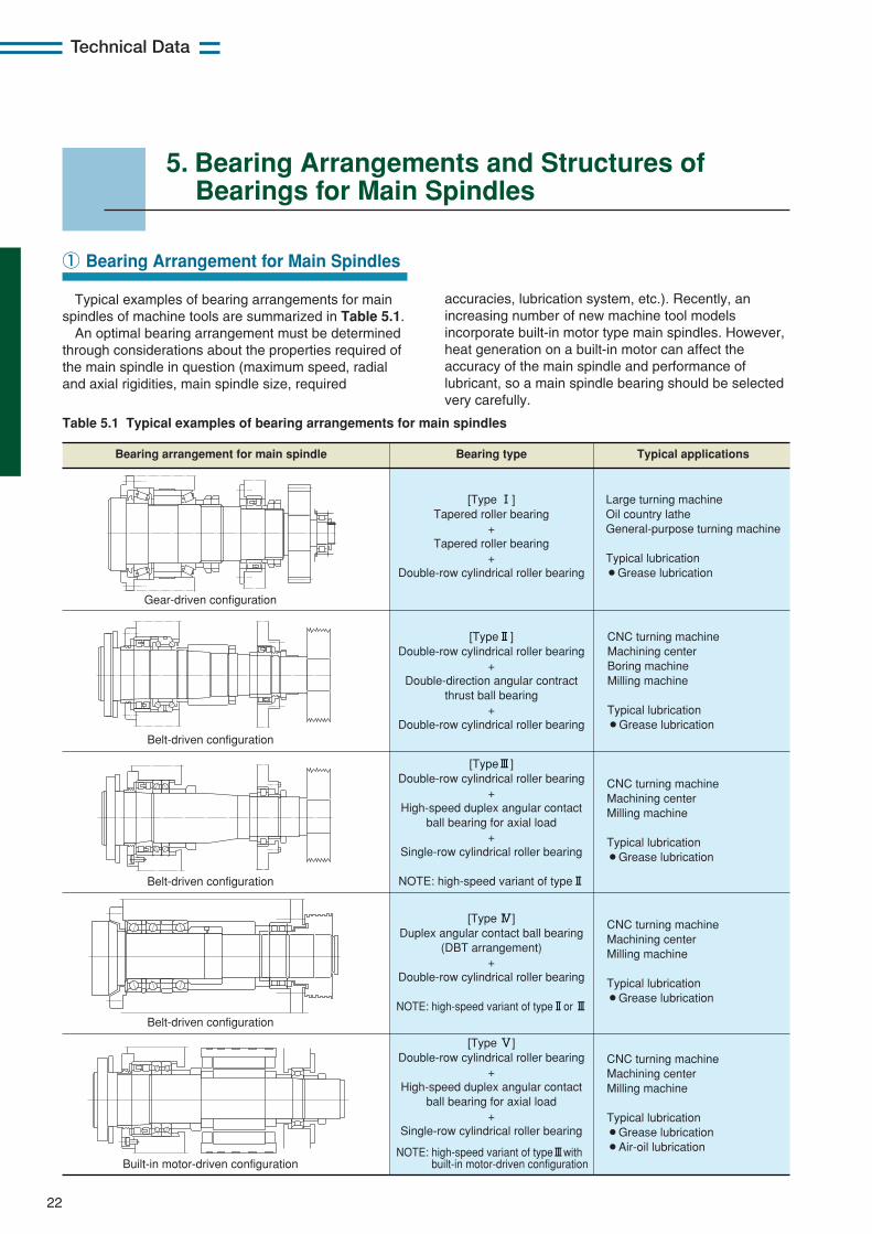
■Allowable axial loadA greater axial load can be exerted on a main spindle
bearing on a machine tool allowing for tool changeswhile the machine is stationary. When an angularcontact ball bearing is subjected to a larger axial load,the contact ellipse between its rolling elements andraceway surface can overflow the raceway surface(Fig. 3.10). Furthermore, even if the contact ellipseremains within the raceway surface, overstressing cancause problems such as denting.
The maximum allowable load that does not causesuch problems is defined as the "allowable axial load."
The allowable axial load is reached when either of thefollowing conditions occurs.
・The end of contact ellipse on the racewaysurface reaches the shoulder of either an inneror outer ring.
・The contact surface pressure on the racewaysurface reaches 3650 MPa in either the inner orouter ring raceway.
Note that the contact surface pressure of 3650 MPaon the raceway surface is a value that leads to apermanent deformation of 0.00002 to 0.00005 times asmuch as the rolling element diameter and has beendetermined through many years of experience.
The allowable axial load for each bearing is found inthe associated dimensions table.
Table 3.3 Minimum safety factor values So
Operating conditions Ball bearings Roller bearings
High rotational accuracy necessary 2
1
0.5
3
1.5
1
Normal rotating accuracy necessary (Universal application)
Slight rotational accuracy deterioration permitted (Low speed, heavy loading, etc.)
Note: When vibration and/or shock loads are present, a load factor based on the shock load needs to be included in the Po max value.
H : a : Fa :
Shoulder height of bearing Semimajor of contact ellipse Axial load
Fa
2a
H
Fig. 3.10
High bearing speed leads to high temperature rise onthe bearing owing to frictional heating within thebearing. When the temperature of the bearing exceedsa particular limit, the lubricant performance deterioratessignificantly, possibly leading to bearing overheating orseizure.
The factors that can affect the maximum allowablebearing speed include:(1) Bearing type(2) Bearing size(3) Lubrication system (grease lubrication, air-oil
lubrication, jet lubrication, etc.)(4) Internal clearance or preload on the bearing(5) Bearing arrangement (2-row, 3-row, 4-row)(6) Bearing load(7) Accuracies of shaft, housing, etc.The maximum allowable speeds listed in the bearing
dimensions tables are reference values and are applicableonly to individual bearings that are adequately lubricatedand correctly preloaded under a condition where the heatis reliably removed from the bearing arrangement.
In the case of grease lubrication, these speeds areattainable only when the bearing is filled with anadequate amount of high-quality grease as given inTable 7.3, the bearing is sufficiently run in, and heat isremoved by an arrangement such as a cooling jacket.In the case of oil lubrication, these speeds are attainedonly by an air-oil lubrication system if an adequateamount of VG10 or 32 spindle oil is supplied and theheat is removed by an arrangement such as a coolingjacket. When using a large amount of lubricant, a jetlubrication system excels in lubrication and coolingperformance, and can permit operation at the maximumallowable speed. However, this lubrication systeminvolves a high power loss and should be employedcarefully.
■Speed factorThe maximum allowable speed of a particular bearing
can vary depending on the relation between heatgeneration and heat dissipation in the bearing as well ashow well the bearing is lubricated. The bearingarrangements (2-row to 4-row) and speed reduction ratios(speed factors) for maximum allowable speed due topost-assembly preloads are summarized in Table 4.1.
4. Allowable Speed
Table 4.1 Speed factor by bearing arrangement and preload
Matching
DB
DBT
DTBT
GL GN GM
0.85 0.8 0.65
0.7 0.6 0.5
0.8 0.75 0.6
Bearing arrangement
5. Bearing Arrangements and Structures ofBearings for Main Spindles
22
Technical Data
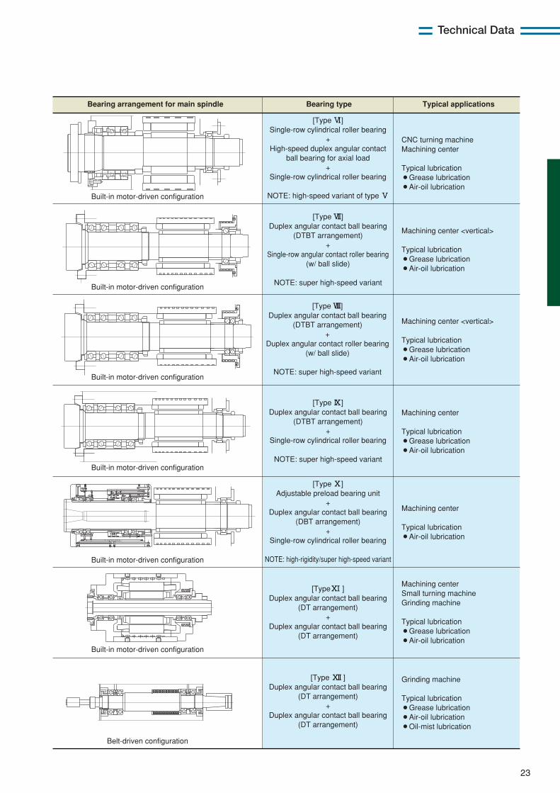
Typical examples of bearing arrangements for mainspindles of machine tools are summarized in Table 5.1.
An optimal bearing arrangement must be determinedthrough considerations about the properties required ofthe main spindle in question (maximum speed, radialand axial rigidities, main spindle size, required
① Bearing Arrangement for Main Spindles
Table 5.1 Typical examples of bearing arrangements for main spindles
Bearing arrangement for main spindle Bearing type
[Type !] Tapered roller bearing
+ Tapered roller bearing
+ Double-row cylindrical roller bearing
Large turning machine Oil country lathe General-purpose turning machine Typical lubrication ¡Grease lubrication
[Type@] Double-row cylindrical roller bearing
+ Double-direction angular contract
thrust ball bearing +
Double-row cylindrical roller bearing
CNC turning machine Machining center Boring machine Milling machine Typical lubrication ¡Grease lubrication
[Type#] Double-row cylindrical roller bearing
+ High-speed duplex angular contact
ball bearing for axial load +
Single-row cylindrical roller bearing
NOTE: high-speed variant of type@
[Type $] Duplex angular contact ball bearing
(DBT arrangement) +
Double-row cylindrical roller bearing
NOTE: high-speed variant of type@or #
[Type %] Double-row cylindrical roller bearing
+ High-speed duplex angular contact
ball bearing for axial load +
Single-row cylindrical roller bearing
CNC turning machine Machining center Milling machine Typical lubrication ¡Grease lubrication
CNC turning machine Machining center Milling machine Typical lubrication ¡Grease lubrication
CNC turning machine Machining center Milling machine Typical lubrication ¡Grease lubrication ¡Air-oil lubrication
Typical applications
Built-in motor-driven configuration
Belt-driven configuration
Belt-driven configuration
Belt-driven configuration
Gear-driven configuration
NOTE: high-speed variant of type#with built-in motor-driven configuration
accuracies, lubrication system, etc.). Recently, anincreasing number of new machine tool modelsincorporate built-in motor type main spindles. However,heat generation on a built-in motor can affect theaccuracy of the main spindle and performance oflubricant, so a main spindle bearing should be selectedvery carefully.
23
Technical Data
[Type ^] Single-row cylindrical roller bearing
+ High-speed duplex angular contact
ball bearing for axial load +
Single-row cylindrical roller bearing
NOTE: high-speed variant of type %
CNC turning machine Machining center Typical lubrication ¡Grease lubrication ¡Air-oil lubrication
[Type &] Duplex angular contact ball bearing
(DTBT arrangement) +
Single-row angular contact roller bearing (w/ ball slide)
NOTE: super high-speed variant
Machining center <vertical> Typical lubrication ¡Grease lubrication ¡Air-oil lubrication
Machining center <vertical> Typical lubrication ¡Grease lubrication ¡Air-oil lubrication
Machining center Typical lubrication ¡Grease lubrication ¡Air-oil lubrication
Machining center Typical lubrication ¡Air-oil lubrication
Machining center Small turning machine Grinding machine Typical lubrication ¡Grease lubrication ¡Air-oil lubrication
[Type *] Duplex angular contact ball bearing
(DTBT arrangement) +
Duplex angular contact roller bearing (w/ ball slide)
NOTE: super high-speed variant
[Type (] Duplex angular contact ball bearing
(DTBT arrangement) +
Single-row cylindrical roller bearing
NOTE: super high-speed variant
[Type )] Adjustable preload bearing unit
+ Duplex angular contact ball bearing
(DBT arrangement) +
Single-row cylindrical roller bearing
NOTE: high-rigidity/super high-speed variant
[Type)!] Duplex angular contact ball bearing
(DT arrangement) +
Duplex angular contact ball bearing (DT arrangement)
Grinding machine Typical lubrication ¡Grease lubrication ¡Air-oil lubrication ¡Oil-mist lubrication
[Type )@] Duplex angular contact ball bearing
(DT arrangement) +
Duplex angular contact ball bearing (DT arrangement)
Built-in motor-driven configuration
Built-in motor-driven configuration
Built-in motor-driven configuration
Built-in motor-driven configuration
Built-in motor-driven configuration
Built-in motor-driven configuration
Belt-driven configuration
Bearing arrangement for main spindle Bearing type Typical applications
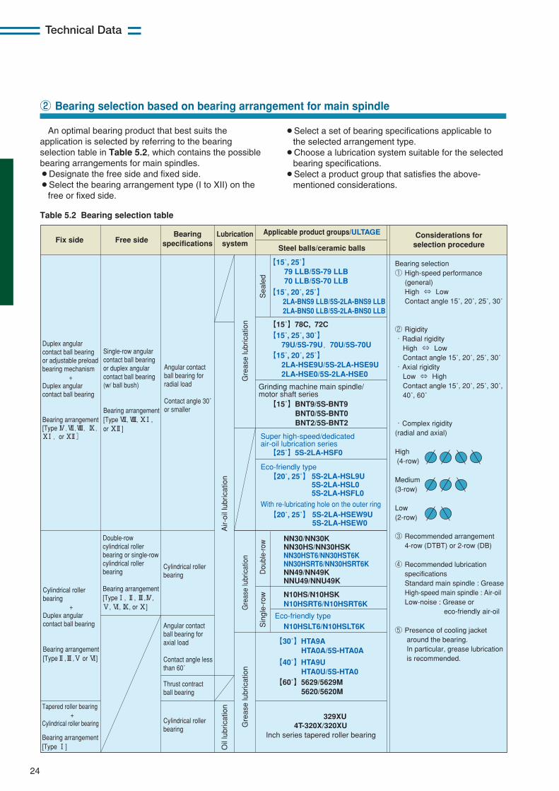
24
Technical Data
An optimal bearing product that best suits theapplication is selected by referring to the bearingselection table in Table 5.2, which contains the possiblebearing arrangements for main spindles.¡Designate the free side and fixed side.¡Select the bearing arrangement type (I to XII) on the
free or fixed side.
② Bearing selection based on bearing arrangement for main spindle
¡Select a set of bearing specifications applicable tothe selected arrangement type.
¡Choose a lubrication system suitable for the selectedbearing specifications.
¡Select a product group that satisfies the above-mentioned considerations.
【20˚, 25˚】
【20˚, 25˚】
Fix side Free sideBearing
specificationsConsiderations for
selection procedureLubrication
system
Duplex angularcontact ball bearingor adjustable preloadbearing mechanism +Duplex angularcontact ball bearing
Bearing arrangement[Type $,&,*,(,)!,or )@]
Single-row angularcontact ball bearingor duplex angularcontact ball bearing(w/ ball bush)
Bearing arrangement[Type &, *, )!,or )@]
Angular contactball bearing forradial load Contact angle 30˚or smaller
Angular contactball bearing foraxial load Contact angle lessthan 60˚
Cylindrical rollerbearing
Thrust contractball bearing
Cylindrical rollerbearing
Double-rowcylindrical rollerbearing or single-rowcylindrical rollerbearing
Bearing arrangement[Type!, @, #,$,%, ^, (, or )]
Cylindrical rollerbearing +Duplex angularcontact ball bearing
Bearing arrangement[Type@,#,% or ^]
Tapered roller bearing +Cylindrical roller bearing
Bearing arrangement[Type !]
Applicable product groups/ULTAGE
Steel balls/ceramic balls
Grinding machine main spindle/motor shaft series
Super high-speed/dedicatedair-oil lubrication series
Eco-friendly type
Eco-friendly type
Inch series tapered roller bearing
329XU 4T-320X/320XU
【25˚】5S-2LA-HSF0
Bearing selection① High-speed performance (general) High ⇔ Low Contact angle 15˚, 20˚, 25˚, 30˚
② Rigidity・Radial rigidity High ⇔ Low Contact angle 15˚, 20˚, 25˚, 30˚ ・Axial rigidity Low ⇔ High Contact angle 15˚, 20˚, 25˚, 30˚, 40˚, 60˚
・Complex rigidity(radial and axial)
High (4-row)
Medium(3-row)
Low(2-row)
③ Recommended arrangement 4-row (DTBT) or 2-row (DB)
④ Recommended lubrication specifications Standard main spindle : Grease High-speed main spindle : Air-oil Low-noise : Grease or eco-friendly air-oil
⑤ Presence of cooling jacket around the bearing. In particular, grease lubrication is recommended.
Air-
oil l
ubric
atio
nO
il lu
bric
atio
n
Gre
ase
lubr
icat
ion
Sea
led
Dou
ble-
row
Sin
gle-
row
Gre
ase
lubr
icat
ion
Gre
ase
lubr
icat
ion
【30˚】HTA9A HTA0A/5S-HTA0A
【40˚】HTA9U HTA0U/5S-HTA0【60˚】5629/5629M 5620/5620M
【15˚, 25˚】 79 LLB/5S-79 LLB 70 LLB/5S-70 LLB
【15˚】78C, 72C
【15˚】BNT9/5S-BNT9 BNT0/5S-BNT0 BNT2/5S-BNT2
NN30/NN30K NN30HS/NN30HSK NN30HST6/NN30HST6K NN30HSRT6/NN30HSRT6K NN49/NN49K NNU49/NNU49K
N10HS/N10HSK N10HSRT6/N10HSRT6K
N10HSLT6/N10HSLT6K
【15˚, 20˚, 25˚】 2LA-BNS9 LLB/5S-2LA-BNS9 LLB 2LA-BNS0 LLB/5S-2LA-BNS0 LLB
【15˚, 20˚, 25˚】 2LA-HSE9U/5S-2LA-HSE9U 2LA-HSE0/5S-2LA-HSE0
5S-2LA-HSL9U 5S-2LA-HSL0 5S-2LA-HSFL0
With re-lubricating hole on the outer ring 5S-2LA-HSEW9U 5S-2LA-HSEW0
【15˚, 25˚, 30˚】 79U/5S-79U,70U/5S-70U
Table 5.2 Bearing selection table
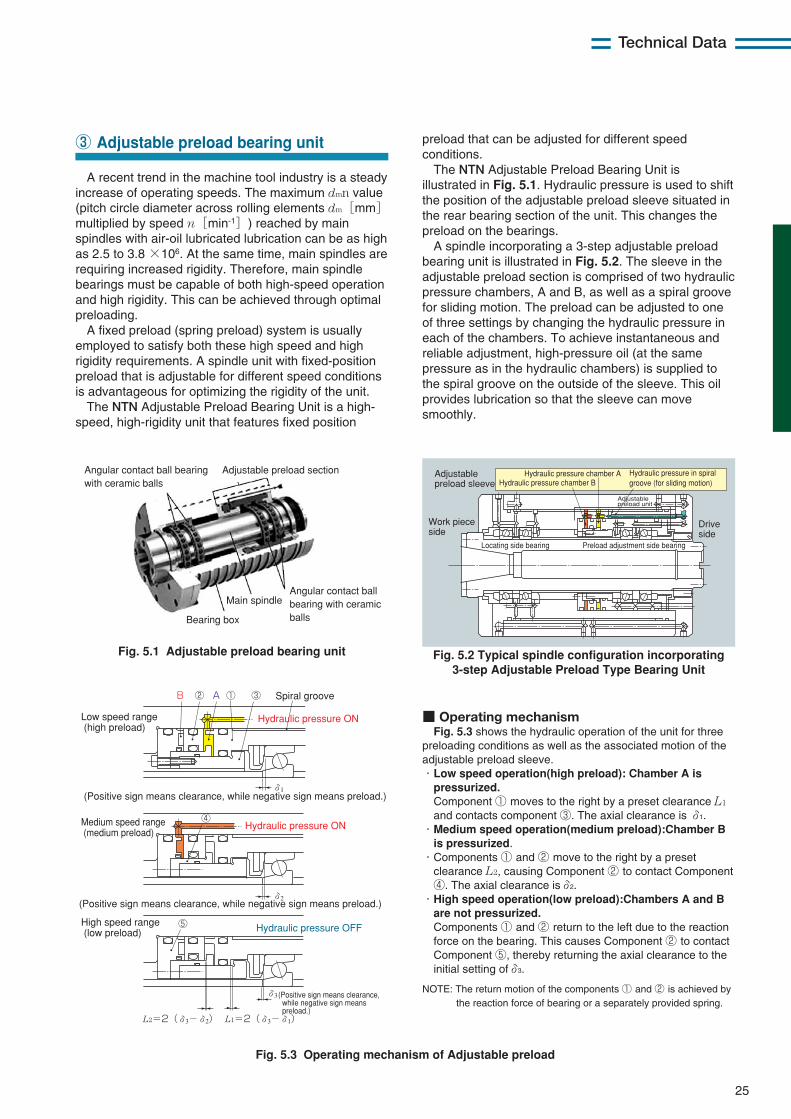
25
Technical Data
preload that can be adjusted for different speedconditions.
The NTN Adjustable Preload Bearing Unit isillustrated in Fig. 5.1. Hydraulic pressure is used to shiftthe position of the adjustable preload sleeve situated inthe rear bearing section of the unit. This changes thepreload on the bearings.
A spindle incorporating a 3-step adjustable preloadbearing unit is illustrated in Fig. 5.2. The sleeve in theadjustable preload section is comprised of two hydraulicpressure chambers, A and B, as well as a spiral groovefor sliding motion. The preload can be adjusted to oneof three settings by changing the hydraulic pressure ineach of the chambers. To achieve instantaneous andreliable adjustment, high-pressure oil (at the samepressure as in the hydraulic chambers) is supplied tothe spiral groove on the outside of the sleeve. This oilprovides lubrication so that the sleeve can movesmoothly.
A recent trend in the machine tool industry is a steadyincrease of operating speeds. The maximum dmn value(pitch circle diameter across rolling elements dm[mm]multiplied by speed n[min-1]) reached by mainspindles with air-oil lubricated lubrication can be as highas 2.5 to 3.8 ×10⁶. At the same time, main spindles arerequiring increased rigidity. Therefore, main spindlebearings must be capable of both high-speed operationand high rigidity. This can be achieved through optimalpreloading.
A fixed preload (spring preload) system is usuallyemployed to satisfy both these high speed and highrigidity requirements. A spindle unit with fixed-positionpreload that is adjustable for different speed conditionsis advantageous for optimizing the rigidity of the unit.
The NTN Adjustable Preload Bearing Unit is a high-speed, high-rigidity unit that features fixed position
③ Adjustable preload bearing unit
Main spindle
Adjustable preload section
Bearing box
Angular contact ball bearing with ceramic balls
Angular contact ball bearing with ceramic balls
Adjustable preload unit
Adjustable preload sleeve
Drive side
Hydraulic pressure chamber AHydraulic pressure chamber B
Locating side bearing Preload adjustment side bearing
Hydraulic pressure in spiral groove (for sliding motion)
Work piece side
Fig. 5.1 Adjustable preload bearing unit
Fig. 5.3 Operating mechanism of Adjustable preload
Fig. 5.2 Typical spindle configuration incorporating3-step Adjustable Preload Type Bearing Unit
L1=2(δ3-δ1)L2=2(δ3-δ2)
Low speed range (high preload)
Medium speed range (medium preload)
High speed range (low preload)
AB
Hydraulic pressure ON
Hydraulic pressure ON
Hydraulic pressure OFF
Spiral groove① ③
④
⑤
②
(Positive sign means clearance, while negative sign means preload.)
(Positive sign means clearance, while negative sign means preload.)
(Positive sign means clearance, while negative sign means preload.)
δ1
δ2
δ3
■ Operating mechanismFig. 5.3 shows the hydraulic operation of the unit for three
preloading conditions as well as the associated motion of theadjustable preload sleeve.・Low speed operation(high preload): Chamber A ispressurized.Component ① moves to the right by a preset clearance L1
and contacts component ③. The axial clearance is δ1.・Medium speed operation(medium preload):Chamber Bis pressurized.
・Components ① and ② move to the right by a presetclearance L2, causing Component ② to contact Component④. The axial clearance isδ2.
・High speed operation(low preload):Chambers A and Bare not pressurized.Components ① and ② return to the left due to the reactionforce on the bearing. This causes Component ② to contactComponent ⑤, thereby returning the axial clearance to theinitial setting ofδ3.
NOTE: The return motion of the components ① and ② is achieved bythe reaction force of bearing or a separately provided spring.
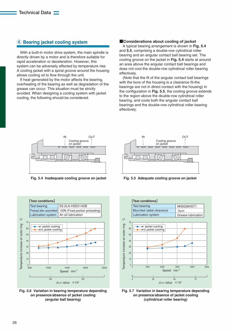
26
Technical Data
■Considerations about cooling of jacketA typical bearing arrangement is shown in Fig. 5.4
and 5.5, comprising a double-row cylindrical rollerbearing and an angular contact ball bearing set. Thecooling groove on the jacket in Fig. 5.4 starts at aroundan area above the angular contact ball bearings anddoes not cool the double-row cylindrical roller bearingeffectively.
(Note that the fit of the angular contact ball bearingswith the bore of the housing is a clearance fit-thebearings are not in direct contact with the housing) Inthe configuration in Fig. 5.5, the cooling groove extendsto the region above the double-row cylindrical rollerbearing, and cools both the angular contact ballbearings and the double-row cylindrical roller bearingeffectively.
With a built-in motor drive system, the main spindle isdirectly driven by a motor and is therefore suitable forrapid acceleration or deceleration. However, thissystem can be adversely affected by temperature rise.A cooling jacket with a spiral groove around the housingallows cooling oil to flow through the unit.
If heat generated by the motor affects the bearing,overheating of the bearing as well as degradation of thegrease can occur. This situation must be strictlyavoided. When designing a cooling system with jacketcooling, the following should be considered.
④ Bearing jacket cooling system
Fig. 5.4 Inadequate cooling groove on jacket Fig. 5.5 Adequate cooling groove on jacket
IN INOUT OUTCooling groove on jacket
Cooling groove on jacket
Fig. 5.6 Variation in bearing temperature dependingon presence/absence of jacket cooling
(angular ball bearing)
Fig. 5.7 Variation in bearing temperature dependingon presence/absence of jacket cooling
(cylindrical roller bearing)
6000
100 150
10000 14000 22000180000
10
20
30
40
50
60
70
Speed min-1
dmn value ×104
Tem
pera
ture
incr
ease
on
oute
r rin
g ˚
C
【Test conditions】
Test bearingPreload after assembledLubrication system
5S-2LA-HSE014DB100N (Fixed position preloading)Air-oil lubrication
w/o jacket coolingw/ jacket cooling
0
0 25 50 75
1000 2000 5000400030000
10
20
30
40
50
60
70
Speed min-1
dmn value ×104
Tem
pera
ture
incr
ease
on
oute
r rin
g ˚
C
【Test conditions】
Test bearingMounted radial clearanceLubrication system
NN3028HST7-5µmGrease lubrication
w/o jacket coolingw/ jacket cooling
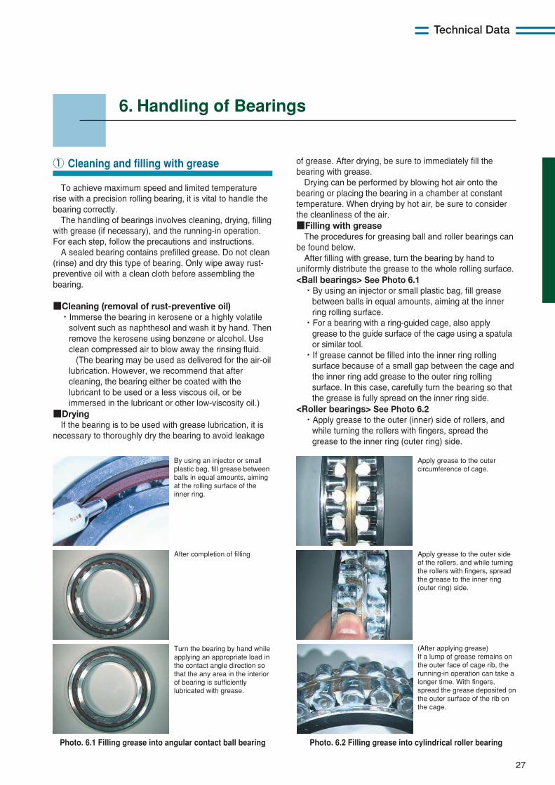
27
Technical Data
6. Handling of Bearings
of grease. After drying, be sure to immediately fill thebearing with grease.
Drying can be performed by blowing hot air onto thebearing or placing the bearing in a chamber at constanttemperature. When drying by hot air, be sure to considerthe cleanliness of the air.■Filling with grease
The procedures for greasing ball and roller bearings canbe found below.
After filling with grease, turn the bearing by hand touniformly distribute the grease to the whole rolling surface.<Ball bearings> See Photo 6.1・By using an injector or small plastic bag, fill grease
between balls in equal amounts, aiming at the innerring rolling surface.
・For a bearing with a ring-guided cage, also applygrease to the guide surface of the cage using a spatulaor similar tool.
・If grease cannot be filled into the inner ring rollingsurface because of a small gap between the cage andthe inner ring add grease to the outer ring rollingsurface. In this case, carefully turn the bearing so thatthe grease is fully spread on the inner ring side.
<Roller bearings> See Photo 6.2・Apply grease to the outer (inner) side of rollers, and
while turning the rollers with fingers, spread thegrease to the inner ring (outer ring) side.
To achieve maximum speed and limited temperaturerise with a precision rolling bearing, it is vital to handle thebearing correctly.
The handling of bearings involves cleaning, drying, fillingwith grease (if necessary), and the running-in operation.For each step, follow the precautions and instructions.
A sealed bearing contains prefilled grease. Do not clean(rinse) and dry this type of bearing. Only wipe away rust-preventive oil with a clean cloth before assembling thebearing.
■Cleaning (removal of rust-preventive oil)・Immerse the bearing in kerosene or a highly volatile
solvent such as naphthesol and wash it by hand. Thenremove the kerosene using benzene or alcohol. Useclean compressed air to blow away the rinsing fluid.
(The bearing may be used as delivered for the air-oillubrication. However, we recommend that aftercleaning, the bearing either be coated with thelubricant to be used or a less viscous oil, or beimmersed in the lubricant or other low-viscosity oil.)
■DryingIf the bearing is to be used with grease lubrication, it is
necessary to thoroughly dry the bearing to avoid leakage
① Cleaning and filling with grease
Photo. 6.1 Filling grease into angular contact ball bearing Photo. 6.2 Filling grease into cylindrical roller bearing
By using an injector or small plastic bag, fill grease between balls in equal amounts, aiming at the rolling surface of the inner ring.
Apply grease to the outer circumference of cage.
Apply grease to the outer side of the rollers, and while turning the rollers with fingers, spread the grease to the inner ring (outer ring) side.
(After applying grease) If a lump of grease remains on the outer face of cage rib, the running-in operation can take a longer time. With fingers, spread the grease deposited on the outer surface of the rib on the cage.
After completion of filling
Turn the bearing by hand while applying an appropriate load in the contact angle direction so that the any area in the interior of bearing is sufficiently lubricated with grease.
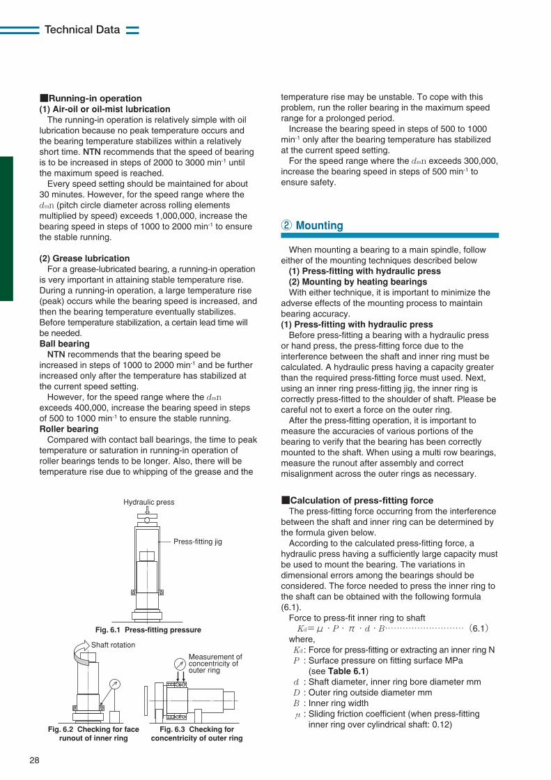
■Calculation of press-fitting forceThe press-fitting force occurring from the interference
between the shaft and inner ring can be determined bythe formula given below.
According to the calculated press-fitting force, ahydraulic press having a sufficiently large capacity mustbe used to mount the bearing. The variations indimensional errors among the bearings should beconsidered. The force needed to press the inner ring tothe shaft can be obtained with the following formula(6.1).
Force to press-fit inner ring to shaftKd=μ・P・π・d・B………………………(6.1)
where,Kd : Force for press-fitting or extracting an inner ring NP : Surface pressure on fitting surface MPa
(see Table 6.1)d : Shaft diameter, inner ring bore diameter mmD : Outer ring outside diameter mmB : Inner ring widthμ : Sliding friction coefficient (when press-fitting
inner ring over cylindrical shaft: 0.12)
28
Technical Data
■Running-in operation(1) Air-oil or oil-mist lubrication
The running-in operation is relatively simple with oillubrication because no peak temperature occurs andthe bearing temperature stabilizes within a relativelyshort time. NTN recommends that the speed of bearingis to be increased in steps of 2000 to 3000 min-1 untilthe maximum speed is reached.
Every speed setting should be maintained for about30 minutes. However, for the speed range where thedmn (pitch circle diameter across rolling elementsmultiplied by speed) exceeds 1,000,000, increase thebearing speed in steps of 1000 to 2000 min-1 to ensurethe stable running.
(2) Grease lubricationFor a grease-lubricated bearing, a running-in operation
is very important in attaining stable temperature rise.During a running-in operation, a large temperature rise(peak) occurs while the bearing speed is increased, andthen the bearing temperature eventually stabilizes.Before temperature stabilization, a certain lead time willbe needed.Ball bearing
NTN recommends that the bearing speed beincreased in steps of 1000 to 2000 min-1 and be furtherincreased only after the temperature has stabilized atthe current speed setting.
However, for the speed range where the dmnexceeds 400,000, increase the bearing speed in stepsof 500 to 1000 min-1 to ensure the stable running.Roller bearing
Compared with contact ball bearings, the time to peaktemperature or saturation in running-in operation ofroller bearings tends to be longer. Also, there will betemperature rise due to whipping of the grease and the
When mounting a bearing to a main spindle, followeither of the mounting techniques described below (1) Press-fitting with hydraulic press(2) Mounting by heating bearingsWith either technique, it is important to minimize the
adverse effects of the mounting process to maintainbearing accuracy.(1) Press-fitting with hydraulic press
Before press-fitting a bearing with a hydraulic pressor hand press, the press-fitting force due to theinterference between the shaft and inner ring must becalculated. A hydraulic press having a capacity greaterthan the required press-fitting force must used. Next,using an inner ring press-fitting jig, the inner ring iscorrectly press-fitted to the shoulder of shaft. Please becareful not to exert a force on the outer ring.
After the press-fitting operation, it is important tomeasure the accuracies of various portions of thebearing to verify that the bearing has been correctlymounted to the shaft. When using a multi row bearings,measure the runout after assembly and correctmisalignment across the outer rings as necessary.
② Mounting
Hydraulic press
Press-fitting jig
Fig. 6.1 Press-fitting pressure
Fig. 6.3 Checking for concentricity of outer ring
Fig. 6.2 Checking for face runout of inner ring
Shaft rotation
Measurement of concentricity of outer ring
temperature rise may be unstable. To cope with thisproblem, run the roller bearing in the maximum speedrange for a prolonged period.
Increase the bearing speed in steps of 500 to 1000min-1 only after the bearing temperature has stabilizedat the current speed setting.
For the speed range where the dmn exceeds 300,000,increase the bearing speed in steps of 500 min-1 toensure safety.
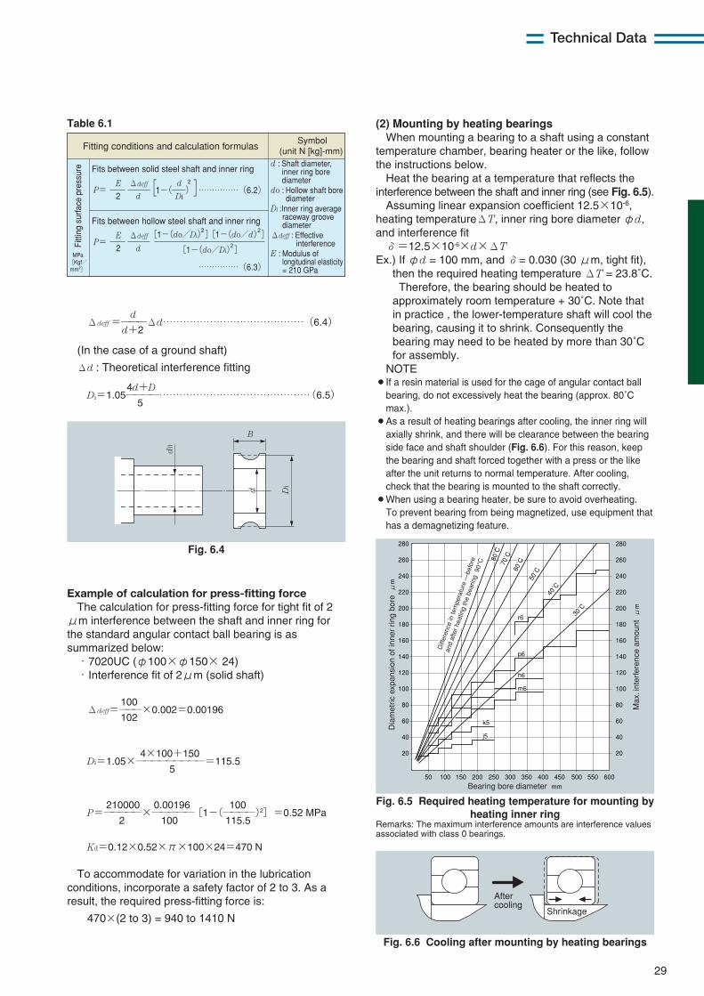
29
Technical Data
dΔdeff =———Δd……………………………………(6.4)
d+2
(In the case of a ground shaft)
Δd : Theoretical interference fitting
4d+DDi=1.05————………………………………………(6.5)
5
Table 6.1
Fitting conditions and calculation formulas
MPa [Kgf/ mm2]
Fits between solid steel shaft and inner ring
Fits between hollow steel shaft and inner ring
P= 2
2E
Di
d
d
Δdeff ] [ 1-( ) ……………(6.2)
P= 2 2
E
d
Δdeff
[1-(do/Di)]
2[1-(do/Di)] 2[1-(do/d)]
Symbol (unit N [kg]-mm)
……………(6.3)
d : Shaft diameter, inner ring bore diameter do : Hollow shaft bore diameter Di :Inner ring average raceway groove diameter Δdeff : Effective interference E : Modulus of longitudinal elasticity = 210 GPa
Fitti
ng s
urfa
ce p
ress
ure
Example of calculation for press-fitting forceThe calculation for press-fitting force for tight fit of 2
μm interference between the shaft and inner ring forthe standard angular contact ball bearing is assummarized below:
・7020UC (φ100×φ150× 24)・Interference fit of 2μm (solid shaft)
100Δdeff=———×0.002=0.00196
102
4×100+150Di=1.05×—————————=115.5
5
210000 0.00196 100P=—————×—————[1−(————)2]=0.52 MPa
2 100 115.5
Kd=0.12×0.52×π×100×24=470 N
To accommodate for variation in the lubricationconditions, incorporate a safety factor of 2 to 3. As aresult, the required press-fitting force is:
470×(2 to 3) = 940 to 1410 N
Fig. 6.4
Fig. 6.5 Required heating temperature for mounting byheating inner ring
Remarks: The maximum interference amounts are interference valuesassociated with class 0 bearings.
Fig. 6.6 Cooling after mounting by heating bearings
B
d0
Di
d
(2) Mounting by heating bearings When mounting a bearing to a shaft using a constant
temperature chamber, bearing heater or the like, followthe instructions below.
Heat the bearing at a temperature that reflects theinterference between the shaft and inner ring (see Fig. 6.5).
Assuming linear expansion coefficient 12.5×10⁻⁶,heating temperatureΔT, inner ring bore diameter φd,and interference fit
δ=12.5×10⁻⁶×d×ΔTEx.) If φd = 100 mm, and δ= 0.030 (30 μm, tight fit),
then the required heating temperature ΔT = 23.8˚C.Therefore, the bearing should be heated to
approximately room temperature + 30˚C. Note thatin practice , the lower-temperature shaft will cool thebearing, causing it to shrink. Consequently thebearing may need to be heated by more than 30˚Cfor assembly.
NOTE¡If a resin material is used for the cage of angular contact ball
bearing, do not excessively heat the bearing (approx. 80˚Cmax.).
¡As a result of heating bearings after cooling, the inner ring willaxially shrink, and there will be clearance between the bearingside face and shaft shoulder (Fig. 6.6). For this reason, keepthe bearing and shaft forced together with a press or the likeafter the unit returns to normal temperature. After cooling,check that the bearing is mounted to the shaft correctly.
¡When using a bearing heater, be sure to avoid overheating.To prevent bearing from being magnetized, use equipment thathas a demagnetizing feature.
280
260
240
220
200
180
160
140
120
100
80
60
40
20
50 100 150 200 250 300 350 400 450 500 550 600
280
260
240
220
200
180
160
140
120
100
80
60
40
20
r6
Dia
met
ric e
xpan
sion
of i
nner
rin
g bo
re μ
m
Max
. int
erfe
renc
e am
ount
μm
j5
30˚C
k5
m6
n6
p6
40˚C
50˚C60
˚C70˚C80
˚C
Bearing bore diameter mm
Diff
eren
ce in
tem
pera
ture
—be
fore
and
afte
r hea
ting
the
bear
ing
90°
C
After cooling
Shrinkage
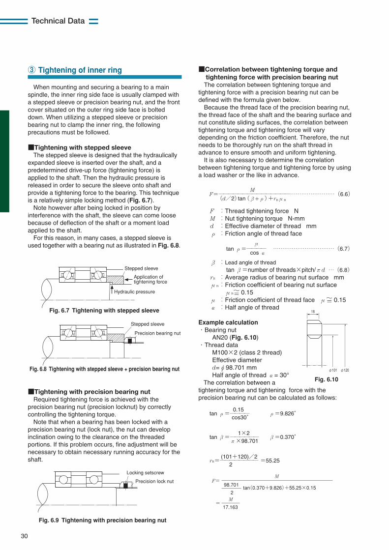
30
Technical Data
When mounting and securing a bearing to a mainspindle, the inner ring side face is usually clamped witha stepped sleeve or precision bearing nut, and the frontcover situated on the outer ring side face is bolteddown. When utilizing a stepped sleeve or precisionbearing nut to clamp the inner ring, the followingprecautions must be followed.
■Tightening with stepped sleeveThe stepped sleeve is designed that the hydraulically
expanded sleeve is inserted over the shaft, and apredetermined drive-up force (tightening force) isapplied to the shaft. Then the hydraulic pressure isreleased in order to secure the sleeve onto shaft andprovide a tightening force to the bearing. This techniqueis a relatively simple locking method (Fig. 6.7).
Note however after being locked in position byinterference with the shaft, the sleeve can come loosebecause of deflection of the shaft or a moment loadapplied to the shaft.
For this reason, in many cases, a stepped sleeve isused together with a bearing nut as illustrated in Fig. 6.8.
■Correlation between tightening torque andtightening force with precision bearing nut
The correlation between tightening torque andtightening force with a precision bearing nut can bedefined with the formula given below.
Because the thread face of the precision bearing nut,the thread face of the shaft and the bearing surface andnut constitute sliding surfaces, the correlation betweentightening torque and tightening force will varydepending on the friction coefficient. Therefore, the nutneeds to be thoroughly run on the shaft thread inadvance to ensure smooth and uniform tightening.
It is also necessary to determine the correlationbetween tightening torque and tightening force by usinga load washer or the like in advance.
MF=———————————————……………………(6.6)
(d/2)tan(β+ρ)+rnμn
F :Thread tightening force NM :Nut tightening torque N-mmd :Effective diameter of thread mmρ :Friction angle of thread face
μtan ρ=———— ……………………………(6.7)
cos α
β :Lead angle of threadtan β=number of threads×pitch/πd …(6.8)
rn :Average radius of bearing nut surface mmμn:Friction coefficient of bearing nut surface
μn〜= 0.15μ :Friction coefficient of thread face μ〜= 0.15α :Half angle of thread
Example calculation・Bearing nut
AN20 (Fig. 6.10)・Thread data
M100×2 (class 2 thread)Effective diameterd=φ98.701 mmHalf angle of thread α= 30°
The correlation between atightening torque and tightening force with theprecision bearing nut can be calculated as follows:
0.15tan ρ=———— ρ=9.826゜
cos30゜
1×2tan β=—————— β=0.370゜
π×98.701
(101+120)/2rn=———————— =55.25
2
③ Tightening of inner ring
Fig. 6.7 Tightening with stepped sleeve
Fig. 6.8 Tightening with stepped sleeve + precision bearing nut
Stepped sleeve
Application of tightening force
Stepped sleeve
Precision bearing nut
Hydraulic pressure
■Tightening with precision bearing nutRequired tightening force is achieved with the
precision bearing nut (precision locknut) by correctlycontrolling the tightening torque.
Note that when a bearing has been locked with aprecision bearing nut (lock nut), the nut can developinclination owing to the clearance on the threadedportions. If this problem occurs, fine adjustment will benecessary to obtain necessary running accuracy for theshaft.
Fig. 6.9 Tightening with precision bearing nut
Locking setscrew
Precision lock nut
Fig. 6.10
F= 98.701
2tan(0.370+9.826)+55.25×0.15
= M
M
17.163
φ101 φ120
18
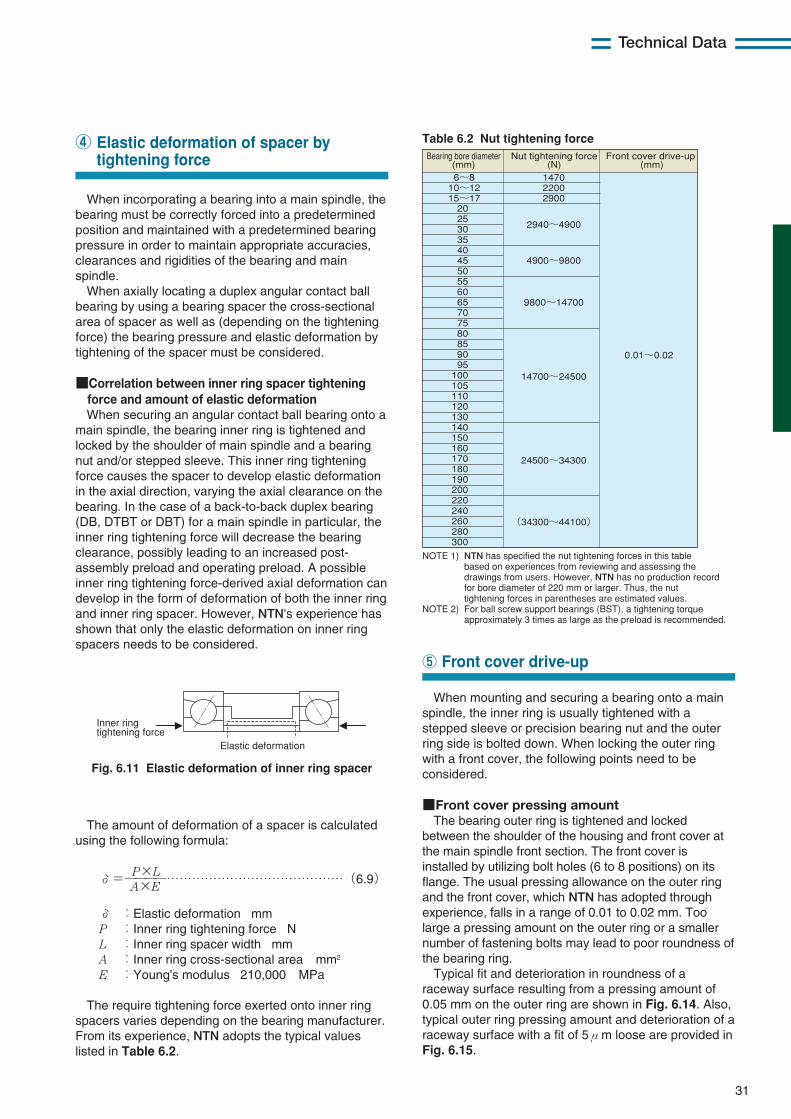
31
Technical Data
When incorporating a bearing into a main spindle, thebearing must be correctly forced into a predeterminedposition and maintained with a predetermined bearingpressure in order to maintain appropriate accuracies,clearances and rigidities of the bearing and mainspindle.
When axially locating a duplex angular contact ballbearing by using a bearing spacer the cross-sectionalarea of spacer as well as (depending on the tighteningforce) the bearing pressure and elastic deformation bytightening of the spacer must be considered.
■Correlation between inner ring spacer tightening force and amount of elastic deformationWhen securing an angular contact ball bearing onto a
main spindle, the bearing inner ring is tightened andlocked by the shoulder of main spindle and a bearingnut and/or stepped sleeve. This inner ring tighteningforce causes the spacer to develop elastic deformationin the axial direction, varying the axial clearance on thebearing. In the case of a back-to-back duplex bearing(DB, DTBT or DBT) for a main spindle in particular, theinner ring tightening force will decrease the bearingclearance, possibly leading to an increased post-assembly preload and operating preload. A possibleinner ring tightening force-derived axial deformation candevelop in the form of deformation of both the inner ringand inner ring spacer. However, NTN's experience hasshown that only the elastic deformation on inner ringspacers needs to be considered.
Table 6.2 Nut tightening force④ Elastic deformation of spacer bytightening force
Fig. 6.11 Elastic deformation of inner ring spacer
Elastic deformation
Inner ring tightening force
The amount of deformation of a spacer is calculatedusing the following formula:
P×Lδ=————……………………………………(6.9)A×E
δ :Elastic deformation mmP :Inner ring tightening force NL :Inner ring spacer width mmA :Inner ring cross-sectional area mm2
E :Young's modulus 210,000 MPa
The require tightening force exerted onto inner ringspacers varies depending on the bearing manufacturer.From its experience, NTN adopts the typical valueslisted in Table 6.2.
NOTE 1) NTN has specified the nut tightening forces in this table based on experiences from reviewing and assessing the drawings from users. However, NTN has no production record for bore diameter of 220 mm or larger. Thus, the nut tightening forces in parentheses are estimated values.NOTE 2) For ball screw support bearings (BST), a tightening torque approximately 3 times as large as the preload is recommended.
20253035404550556065707580859095
100105110120130140150160170180190200220240260280300
6~810~1215~17
2940~4900
290022001470
4900~9800
9800~14700
14700~24500
0.01~0.02
24500~34300
(34300~44100)
Bearing bore diameter(mm)
Nut tightening force(N)
Front cover drive-up (mm)
When mounting and securing a bearing onto a mainspindle, the inner ring is usually tightened with astepped sleeve or precision bearing nut and the outerring side is bolted down. When locking the outer ringwith a front cover, the following points need to beconsidered.
■Front cover pressing amount The bearing outer ring is tightened and locked
between the shoulder of the housing and front cover atthe main spindle front section. The front cover isinstalled by utilizing bolt holes (6 to 8 positions) on itsflange. The usual pressing allowance on the outer ringand the front cover, which NTN has adopted throughexperience, falls in a range of 0.01 to 0.02 mm. Toolarge a pressing amount on the outer ring or a smallernumber of fastening bolts may lead to poor roundness ofthe bearing ring.
Typical fit and deterioration in roundness of araceway surface resulting from a pressing amount of0.05 mm on the outer ring are shown in Fig. 6.14. Also,typical outer ring pressing amount and deterioration of araceway surface with a fit of 5μm loose are provided inFig. 6.15.
⑤ Front cover drive-up
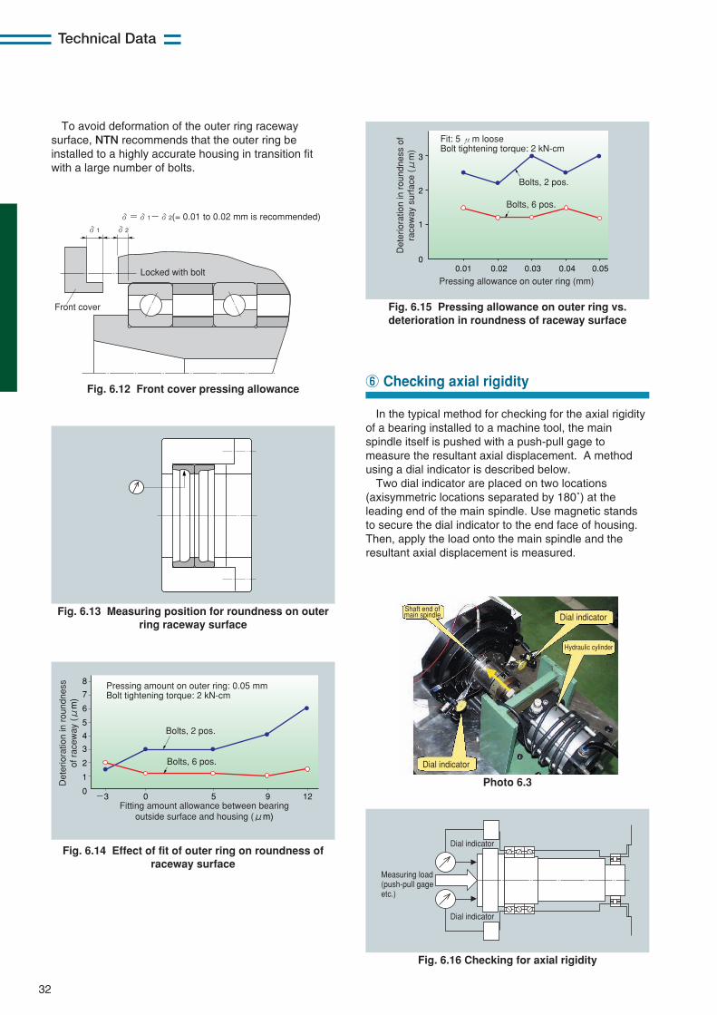
In the typical method for checking for the axial rigidityof a bearing installed to a machine tool, the mainspindle itself is pushed with a push-pull gage tomeasure the resultant axial displacement. A methodusing a dial indicator is described below.
Two dial indicator are placed on two locations(axisymmetric locations separated by 180˚) at theleading end of the main spindle. Use magnetic standsto secure the dial indicator to the end face of housing.Then, apply the load onto the main spindle and theresultant axial displacement is measured.
32
Technical DataD
eter
iora
tion
in r
ound
ness
of
rac
eway
(μ
m)
Pressing amount on outer ring: 0.05 mm Bolt tightening torque: 2 kN-cm
Bolts, 2 pos.
Bolts, 6 pos.
8
7
-3 0 5 9 12
6
5
4
3
2
1
0
Fitting amount allowance between bearing outside surface and housing (μm)
Fit: 5 μm loose Bolt tightening torque: 2 kN-cm
3
2
0.01 0.02 0.03 0.04 0.05
1
0
Det
erio
ratio
n in
rou
ndne
ss o
f ra
cew
ay s
urfa
ce (μ
m)
Pressing allowance on outer ring (mm)
Bolts, 2 pos.
Bolts, 6 pos.
Deterioration in roundness of raceway surface (μm) #13 #14 #15
Fig. 6.13 Measuring position for roundness on outerring raceway surface
Fig. 6.12 Front cover pressing allowance
Fig. 6.14 Effect of fit of outer ring on roundness ofraceway surface
Fig. 6.15 Pressing allowance on outer ring vs.deterioration in roundness of raceway surface
Fig. 6.16 Checking for axial rigidity
Photo 6.3
δ=δ1-δ2(= 0.01 to 0.02 mm is recommended)
Front cover
Locked with bolt
δ1 δ2
⑥ Checking axial rigidity
Dial indicator
Dial indicator
Hydraulic cylinder
Shaft end of main spindle
Dial indicator
Dial indicator
Measuring load (push-pull gage etc.)
To avoid deformation of the outer ring racewaysurface, NTN recommends that the outer ring beinstalled to a highly accurate housing in transition fitwith a large number of bolts.
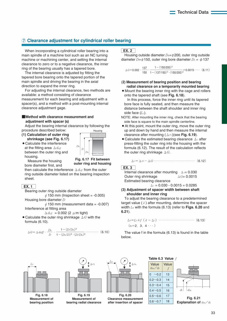
33
Technical Data
When incorporating a cylindrical roller bearing into amain spindle of a machine tool such as an NC turningmachine or machining center, and setting the internalclearance to zero or to a negative clearance, the innerring of the bearing usually has a tapered bore.
The internal clearance is adjusted by fitting thetapered bore bearing onto the tapered portion of themain spindle and driving the bearing in the axialdirection to expand the inner ring.
For adjusting the internal clearance, two methods areavailable: a method consisting of clearancemeasurement for each bearing and adjustment with aspacer(s), and a method with a post-mounting internalclearance adjustment gage.
■Method with clearance measurement andadjustment with spacer (s)Adjust the bearing internal clearance by following the
procedure described below:(1) Calculation of outer ring
shrinkage (see Fig. 6.17)¡Calculate the interference
at the fitting area Δdeff
between the outer ring andhousing.
Measure the housingbore diameter first, andthen calculate the interference Δdeff from the outerring outside diameter listed on the bearing inspectionsheet.
EX. 1Bearing outer ring outside diameter
φ150 mm (Inspection sheet = -0.005)Housing bore diameter D
φ150 mm (measurement data = -0.007)Interference at fitting area
Δdeff = 0.002 (2 μm tight)¡Calculate the outer ring shrinkage ΔG with the
formula (6.10).
⑦ Clearance adjustment for cylindrical roller bearing
Dh
DD0
Housing
Fig. 6.17 Fit betweenouter ring and housing
ΔG=0.002・ ・ ……(6.11) 150
137
1-(137/150)2・(150/200)2
1-(150/200)2
=0.0015
ΔG=Δdeff・ ・ …………(6.10) D
D0
1-(D0/D)2・(D/Dh)2
1-(D/Dh)2
Fig. 6.18 Measurement of bearing position
Fig. 6.19 Measurement of
bearing radial clearance
Fig. 6.20 Clearance measurement after insertion of spacer
L1Ln
Δr1 Δrn
Table 6.3 Value f
Value dm/di
Value f
0 ~0.2 13
14
15
16
17
18
0.2~0.3
0.3~0.4
0.4~0.5
0.5~0.6
0.6~0.7
di dm
Fig. 6.21 Explanation of dm/di
(2) Measurement of bearing position and bearingradial clearance on a temporarily mounted bearing
¡Mount the bearing inner ring with the cage and rollersonto the tapered shaft (see Fig. 6.18).
In this process, force the inner ring until its taperedbore face is fully seated, and then measure thedistance between the shaft shoulder and inner ringside face (L1).
NOTE: After mounting the inner ring, check that the bearingside face is square to the main spindle centerline.
¡At this point, mount the outer ring, move the outer ringup and down by hand and then measure the internalclearance after mounting (Δr1)(see Fig. 6.19).
¡Calculate the estimated bearing clearance Δ1 afterpress-fitting the outer ring into the housing with theformula (6.12). The result of the calculation reflectsthe outer ring shrinkage ΔG.
Δ1=Δr1−ΔG…………………………………(6.12)
EX. 3Internal clearance after mounting Δ1= 0.030Outer ring shrinkage ΔG= 0.0015Estimated bearing clearance
Δ1 = 0.030 - 0.0015 = 0.0285(3) Adjustment of spacer width between shaft
shoulder and inner ringTo adjust the bearing clearance to a predetermined
target value (δ) after mounting, determine the spacerwidth Ln with the formula (6.13) (refer to Figs. 6.20 and6.21).
Ln=L1+f(δ−Δ1)……………………………(6.13)
(n=2,3,4・・・)
The value f in the formula (6.13) is found in the tablebelow.
EX. 2Housing outside diameter Dh=φ200, outer ring outside
diameter D=φ150, outer ring bore diameter D0 = φ137
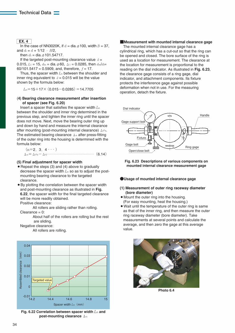
34
Technical Data
EX. 4In the case of NN3020K, if d = dia.φ100, width B = 37,
and di = d + 1/12 ・ B/2,then di = dia.φ101.54717.If the targeted post-mounting clearance value δ=
0.015, L1 = 15, dm = dia.φ60, Δ1 = 0.0285, then dm/di=60/101.5417 = 0.5909, and, therefore, f = 17.
Thus, the spacer width Ln between the shoulder andinner ring equivalent to δ= 0.015 will be the valueshown by the formula below:
Ln=15+17×(0.015−0.0285)=14.7705
(4) Bearing clearance measurement after insertionof spacer (see Fig. 6.20)
Insert a spacer that satisfies the spacer width Ln
between the shoulder and inner ring determined in theprevious step, and tighten the inner ring until the spacerdoes not move. Next, move the bearing outer ring upand down by hand and measure the internal clearanceafter mounting (post-mounting internal clearance) Δrn.The estimated bearing clearance Δn after press-fittingof the outer ring into the housing is determined with theformula below:
(n=2,3,4・・・)Δn=Δrn−ΔG……………………………………(6.14)
(5) Final adjustment for spacer width¡Repeat the steps (3) and (4) above to gradually
decrease the spacer width Ln so as to adjust the post-mounting bearing clearance to the targetedclearance.
¡By plotting the correlation between the spacer widthand post-mounting clearance as illustrated in Fig.6.22, the spacer width for the final targeted clearancewill be more readily obtained.Positive clearance:
All rollers are sliding rather than rolling.Clearance = 0:
About half of the rollers are rolling but the restare sliding.
Negative clearance: All rollers are rolling.
■Measurement with mounted internal clearance gageThe mounted internal clearance gage has a
cylindrical ring, which has a cut-out so that the ring canbe opened and closed. The bore surface of the ring isused as a location for measurement. The clearance atthe location for measurement is proportional to thereading on the dial indicator. As illustrated in Fig. 6.23,the clearance gage consists of a ring gage, dialindicator, and attachment components. Its fixtureprotects the interference gage against possibledeformation when not in use. For the measuringoperation, detach the fixture.
Fig. 6.22 Correlation between spacer width Ln andpost-mounting clearance Δn
Spacer width Ln(mm)
-0.0114.2 14.4 14.6 14.8 15
0
0.01
0.02
0.03
0.04
Ass
embl
ed c
lear
ance(
mm)
Targeted value
Handle
Dial indicator
Gage support bolt
Fixture
Gage bolt
Open/close boltRing gage
NTN
NN30XXK
Fig. 6.23 Descriptions of various components onmounted internal clearance measurement gage
Photo 6.4
●Usage of mounted internal clearance gage
(1) Measurement of outer ring raceway diameter(bore diameter)
¡Mount the outer ring into the housing.(For easy mounting, heat the housing.)
¡Wait until the temperature of the outer ring is sameas that of the inner ring, and then measure the outerring raceway diameter (bore diameter). Takemeasurements at several points and calculate theaverage, and then zero the gage at this averagevalue.
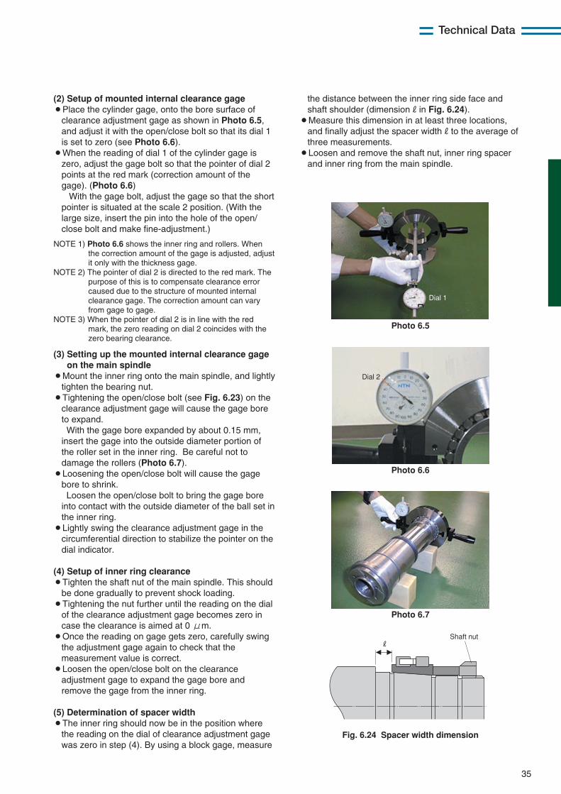
35
Technical Data
(2) Setup of mounted internal clearance gage¡Place the cylinder gage, onto the bore surface of
clearance adjustment gage as shown in Photo 6.5,and adjust it with the open/close bolt so that its dial 1is set to zero (see Photo 6.6).
¡When the reading of dial 1 of the cylinder gage iszero, adjust the gage bolt so that the pointer of dial 2points at the red mark (correction amount of thegage). (Photo 6.6)
With the gage bolt, adjust the gage so that the shortpointer is situated at the scale 2 position. (With thelarge size, insert the pin into the hole of the open/close bolt and make fine-adjustment.)
NOTE 1) Photo 6.6 shows the inner ring and rollers. Whenthe correction amount of the gage is adjusted, adjustit only with the thickness gage.
NOTE 2) The pointer of dial 2 is directed to the red mark. Thepurpose of this is to compensate clearance errorcaused due to the structure of mounted internalclearance gage. The correction amount can varyfrom gage to gage.
NOTE 3) When the pointer of dial 2 is in line with the redmark, the zero reading on dial 2 coincides with thezero bearing clearance.
(3) Setting up the mounted internal clearance gageon the main spindle
¡Mount the inner ring onto the main spindle, and lightlytighten the bearing nut.
¡Tightening the open/close bolt (see Fig. 6.23) on theclearance adjustment gage will cause the gage boreto expand.With the gage bore expanded by about 0.15 mm,
insert the gage into the outside diameter portion ofthe roller set in the inner ring. Be careful not todamage the rollers (Photo 6.7).
¡Loosening the open/close bolt will cause the gagebore to shrink.Loosen the open/close bolt to bring the gage bore
into contact with the outside diameter of the ball set inthe inner ring.
¡Lightly swing the clearance adjustment gage in thecircumferential direction to stabilize the pointer on thedial indicator.
(4) Setup of inner ring clearance¡Tighten the shaft nut of the main spindle. This should
be done gradually to prevent shock loading.¡Tightening the nut further until the reading on the dial
of the clearance adjustment gage becomes zero incase the clearance is aimed at 0 μm.
¡Once the reading on gage gets zero, carefully swingthe adjustment gage again to check that themeasurement value is correct.
¡Loosen the open/close bolt on the clearanceadjustment gage to expand the gage bore andremove the gage from the inner ring.
(5) Determination of spacer width¡The inner ring should now be in the position where
the reading on the dial of clearance adjustment gagewas zero in step (4). By using a block gage, measure
Photo 6.5
Dial 1
Photo 6.6
Dial 2
Photo 6.7
Fig. 6.24 Spacer width dimension
RShaft nut
the distance between the inner ring side face andshaft shoulder (dimensionRin Fig. 6.24).
¡Measure this dimension in at least three locations,and finally adjust the spacer widthRto the average ofthree measurements.
¡Loosen and remove the shaft nut, inner ring spacerand inner ring from the main spindle.
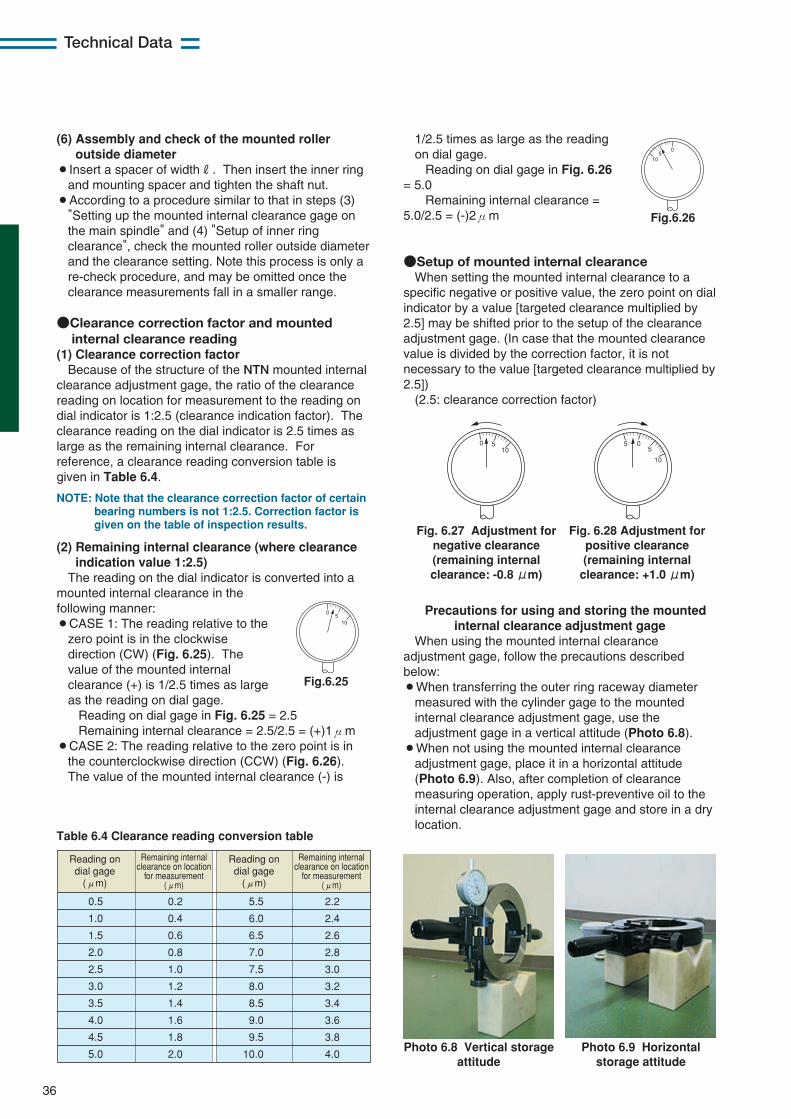
36
Technical Data
(6) Assembly and check of the mounted rolleroutside diameter
¡Insert a spacer of widthR. Then insert the inner ringand mounting spacer and tighten the shaft nut.
¡According to a procedure similar to that in steps (3)"Setting up the mounted internal clearance gage onthe main spindle" and (4) "Setup of inner ringclearance", check the mounted roller outside diameterand the clearance setting. Note this process is only are-check procedure, and may be omitted once theclearance measurements fall in a smaller range.
●Clearance correction factor and mountedinternal clearance reading
(1) Clearance correction factorBecause of the structure of the NTN mounted internal
clearance adjustment gage, the ratio of the clearancereading on location for measurement to the reading ondial indicator is 1:2.5 (clearance indication factor). Theclearance reading on the dial indicator is 2.5 times aslarge as the remaining internal clearance. Forreference, a clearance reading conversion table isgiven in Table 6.4.
NOTE: Note that the clearance correction factor of certainbearing numbers is not 1:2.5. Correction factor isgiven on the table of inspection results.
(2) Remaining internal clearance (where clearanceindication value 1:2.5)
The reading on the dial indicator is converted into amounted internal clearance in thefollowing manner:¡CASE 1: The reading relative to the
zero point is in the clockwisedirection (CW) (Fig. 6.25). Thevalue of the mounted internalclearance (+) is 1/2.5 times as largeas the reading on dial gage.
Reading on dial gage in Fig. 6.25 = 2.5Remaining internal clearance = 2.5/2.5 = (+)1μm
¡CASE 2: The reading relative to the zero point is inthe counterclockwise direction (CCW) (Fig. 6.26).The value of the mounted internal clearance (-) is
●Setup of mounted internal clearanceWhen setting the mounted internal clearance to a
specific negative or positive value, the zero point on dialindicator by a value [targeted clearance multiplied by2.5] may be shifted prior to the setup of the clearanceadjustment gage. (In case that the mounted clearancevalue is divided by the correction factor, it is notnecessary to the value [targeted clearance multiplied by2.5])
(2.5: clearance correction factor)
0510
Fig.6.25
Table 6.4 Clearance reading conversion table
0.5
1.0
1.5
2.0
2.5
3.0
3.5
4.0
4.5
5.0
0.2
0.4
0.6
0.8
1.0
1.2
1.4
1.6
1.8
2.0
5.5
6.0
6.5
7.0
7.5
8.0
8.5
9.0
9.5
10.0
2.2
2.4
2.6
2.8
3.0
3.2
3.4
3.6
3.8
4.0
Remaining internal clearance on location
for measurement (μm)
Remaining internal clearance on location
for measurement (μm)
Reading on dial gage
(μm)
Reading on dial gage
(μm)
0 510
055
10
Fig. 6.27 Adjustment fornegative clearance(remaining internalclearance: -0.8 μm)
Fig. 6.28 Adjustment forpositive clearance(remaining internalclearance: +1.0 μm)
Precautions for using and storing the mountedinternal clearance adjustment gage
When using the mounted internal clearanceadjustment gage, follow the precautions describedbelow:¡When transferring the outer ring raceway diameter
measured with the cylinder gage to the mountedinternal clearance adjustment gage, use theadjustment gage in a vertical attitude (Photo 6.8).
¡When not using the mounted internal clearanceadjustment gage, place it in a horizontal attitude(Photo 6.9). Also, after completion of clearancemeasuring operation, apply rust-preventive oil to theinternal clearance adjustment gage and store in a drylocation.
Photo 6.8 Vertical storageattitude
Photo 6.9 Horizontalstorage attitude
1/2.5 times as large as the readingon dial gage.
Reading on dial gage in Fig. 6.26= 5.0
Remaining internal clearance =5.0/2.5 = (-)2μm
05
10
Fig.6.26
37
Technical Data
In order for a precision bearing to perform asdesigned, it must be correctly mounted to a shaft andhousing. In particular, when employing a tapered borecylindrical roller bearing, accurate finish for the taperedmain spindle and appropriate fit between the bearingbore and the main spindle are very important to ensurehigh accuracy of the main spindle. NTN recommendsthat the customer use the NTN tapered shaft ring gage,which that is finished to same accuracies as thebearing, so that the customer can achieve higherprecision. NTN also offers a plug gage so that thecustomer can check the accuracy of the ring gage.
■Taper gage for precision roller bearingsEach NTN precision cylindrical roller bearing taper
gage consists of a female gage and a male gage (pluggage) (Fig. 6.29).
Using blue paste or an equivalent as well as a ringgage, check the fit of the bearing bore with the mainspindle taper. The correct fit between the main spindleand the bearing leads to higher accuracy of the mainspindle. The plug gage is intended to check theaccuracy of the associated ring gage. Use the pluggage to verify the taper accuracies of the associatedring gage (Fig. 6.30).
■Taper angleNTN machines the tapered bore of its cylindrical roller
bearings and the taper angle of its taper gagesaccording to the tolerances below:¡Nominal taper angle 1/12 (4˚ 46' 18.8")¡Tolerance for precision roller bearing with 1/12 taper
angle is +12"±12" (JIS class 4 and 2)¡Targeted tolerance for taper gage 1/12 is +9”.
⑧ Tapered bore cylindrical roller bearing and main spindle taper angle
Fig. 6.29 Taper gage
Fig. 6.30 Blue paste on taper gage
Ring gage (TB)
φd φdφDφd1
φd1
B
B
Taper 1/12
Taper 1/12
Plug gage (TA)
Fig. 6.31
Usually, Using blue paste between the tapered boreof a cylindrical roller bearing and a plug gage exhibits astrong contact mark on the small diameter side as showin Fig. 6.31. This is because NTN has slightly adjustedthe taper angle of the bearing bore to accommodate forthe difference in thickness of the inner ring below eachrow of rollers.
■Checking main spindle taper with ring gageWhen checking the main spindle taper angle with a
ring gage, perform the following steps.¡Thoroughly clean the surface of the ring gage, and
apply a thin layer of blue paste to four equally-spacedpoints.
¡Clean the tapered surface of the shaft, and gentlyinsert into the ring gage.
¡The ring gage to be lightly turning it.¡Check the patterns of blue paste deposited on the
shaft surface.¡At this point, attach a strip of clear adhesive tape
onto each blue paste spot, and peel off each strip.Attach strips of adhesive tape onto white paper and
check how much blue paste was deposited onto eachpoint. Check that more than 80% of the applied bluepaste was deposited on the tapered surface.
Fig. 6.32 Application of blue paste to ring gage
Table 6.5 Examples of blue paste records
Fig. 6.33 Regions subjected to measurement with
blue paste
Region A
Region B
Region C
Region D
Small: small diameter side Large: large diameter side
Small Large
Small Large
Small Large
Small Large
A
C
BD
38
Technical Data
Run-in is important for ensuringsmooth operation of grease-lubricatedmain spindle bearings.
The following two modes of running-inare recommended:(1) The bearing speed is gradually
increased in steps. After thetemperature is saturated at eachspeed setting, the speed isincreased to the next step (Fig.6.34).
(2) The bearing is run for one minute ataround the maximum operatingspeed of the spindel. This cycle isrepeated two or three times (Fig.6.35) as needed.
(1) is the ordinary method used,however it takes slightly longer to reachthe maximum operating speed of thespindel. In contrast, (2) can shorten therunning-in time, however higher risk ofsudden bearing temperature increase isconsiderable, so that running speed andits holding time must be set carefully.
Generally, the temperature of a mainspindle bearing is measured on the frontcover. The temperature differenceacross the bearing outer ring and frontcover reaches 2 to 3˚C, and at the sametime, the temperature differencebetween the hottest rolling element andthe inner ring raceway surface seems toreach 50 to 10˚C. For this reason, NTNrecommends that the machine isstopped if the temperature on frontcover reaches approximately 60˚C. Themachine should be allowed to cool offbefore the running-in operation isrestarted.
Fig. 6.35
Fig. 6.34
OR
tem
pera
ture ℃
Spe
ed
min
-1
40
35
30
25
200 1 2 3 4 5 6 7 8
0
4000
8000
12000
16000
Time h
OR temperature Room temperature Speed
Spe
ed
min
-1
OR
tem
pera
ture ℃
40
50
60
30
20
10
00 1 2 3 4 5
0
2000
4000
6000
8000
10000
12000
Time h
OR
tem
pera
ture ℃
Spe
ed
min
-1
70
60
50
40
30
20
10
0 2 4 106 12 148
0
1000
2000
3000
4000
5000
6000
Time h
OR
tem
pera
ture ℃
Spe
ed
min
-1
40
50
60
30
20
10
00 0.5 1 1.5 2
0
1000
2000
3000
4000
5000
6000
Time h
OR temperature Room temperature Speed
OR temperature Room temperature Speed
OR temperature Room temperature Speed
Bearing Mounted preload Jacket cooling
5S-7006CDLLBDB(φ30×φ55×13×2 rows) 180N(Fixed-position preload) Yes
Bearing Mounted preload Jacket cooling
5S-2LA-BNS020LLBDB(φ100×φ150×24×2 rows) 4kN(Constant pressure preload) Yes
Bearing Mounted radial clearance Jacket cooling
NN3020HSK(φ100×φ150×37) -5μm Yes
Bearing Mounted radial clearance Jacket cooling
NN3020HSK(φ100×φ150×37) -5μm Yes
⑨ Running-in operation for main spindle bearings
39
Technical Data
7. Lubrication of Bearings
In a bearing, lubrication forms a thin oil film on bothrolling and sliding surfaces to prevent metal-to-metalcontact. The benefits of lubrication can be summarizedas follows:(1) Alleviation of friction and wear(2) Removal of heat due to friction(3) Longer bearing life(4) Rust prevention(5) Protection against contamination by foreign
material
To achieve the full lubricating effect, it is necessary touse a lubricating system suited to the operatingconditions, select a quality lubricant, remove dust fromthe lubricant, and design an appropriate sealingstructure to prevent contamination as well as lubricantleakage.
The main spindle of a machine tool usually uses anextremely low volume of lubricant so heat generationfrom stirring of the lubricant is minimal.Fig. 7.1 summarizes the relationships between oil
volume, friction loss, and bearing temperature.The lubrication methods available for bearings in a
machine tool include grease lubrication, oil mistlubrication, air-oil lubrication, and jet lubrication. Eachmethod has unique advantages. Therefore, thelubricating system that best suits the lubricationrequirements should be used.Tables 7.1 and 7.2 summarize the features of various
lubrication methods.Friction loss
Fric
tion
loss
Oil volume large
EDCBA
Tem
pera
ture
incr
ease
high
high
Temperature increase
Fig. 7.1
Zone
A
B
C
D
E
Features Typical lubrication method
Grease lubrication Oil mist lubrication Air-oil lubrication
Circulating lubrication
Circulating lubrication
Forced circulating lubrication Jet lubrication
----
With an extremely low volume of oil, partial metal-to-metal contact occurs between the rolling elements and raceway surface, possibly leading to abnormal wear and bearing seizure.
A uniform, uninterrupted oil film is formed. Friction is minimal and bearing temperature is kept low.
Even with a greater oil volume, heat generation and cooling are in balance.
A further increase in oil volume contributes to a significant cooling effect, and the bearing temperature drops.
Temperature increase is constant regardless of oil volume.
Table 7.1 Oil volume, friction loss and bearing temperature (Fig. 7.1)
Criterion
Lubrication method Grease
lubricationOil mist
lubricationAir-oil
lubricationJet
lubrication
Handling
Reliability
Cooling effect
Power loss
☆☆☆☆
☆☆☆
☆☆
☆
☆☆
☆☆☆
☆☆☆
1.4×10⁶
☆☆☆
☆☆
☆☆
☆☆
☆☆☆
☆☆☆
☆
2.2×10⁶
☆☆☆
☆☆☆
☆☆☆
☆☆☆
☆☆☆
☆☆☆
☆☆
2.5×10⁶
☆☆
☆☆☆☆
☆☆☆☆
☆☆☆☆
☆
☆
☆☆☆
4.0×10⁶
Temperature increase
Sealing structure
Environmental contamination
Allowable dmn value 1
Legend ☆☆☆☆:Excellent ☆☆☆:Good ☆☆:Fair ☆:Poor 1 The permissible dmn values are approximate values: dmn: pitch circle diameter across rolling elements [mm] multiplied by speed [min-1]
Table 7.2 Evaluation of various lubricating systems
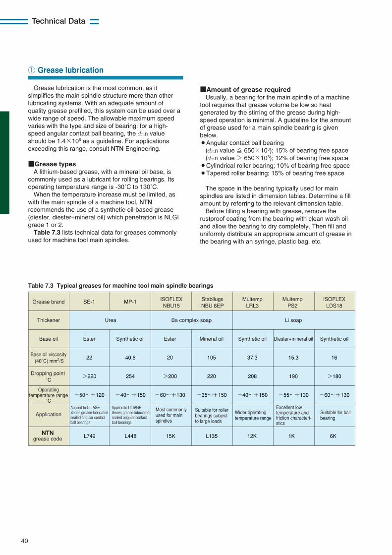
40
Technical Data
Grease lubrication is the most common, as itsimplifies the main spindle structure more than otherlubricating systems. With an adequate amount ofquality grease prefilled, this system can be used over awide range of speed. The allowable maximum speedvaries with the type and size of bearing: for a high-speed angular contact ball bearing, the dmn valueshould be 1.4×10⁶ as a guideline. For applicationsexceeding this range, consult NTN Engineering.
■Grease typesA lithium-based grease, with a mineral oil base, is
commonly used as a lubricant for rolling bearings. Itsoperating temperature range is -30˚C to 130˚C.
When the temperature increase must be limited, aswith the main spindle of a machine tool, NTNrecommends the use of a synthetic-oil-based grease(diester, diester+mineral oil) which penetration is NLGIgrade 1 or 2.Table 7.3 lists technical data for greases commonly
used for machine tool main spindles.
■Amount of grease requiredUsually, a bearing for the main spindle of a machine
tool requires that grease volume be low so heatgenerated by the stirring of the grease during high-speed operation is minimal. A guideline for the amountof grease used for a main spindle bearing is givenbelow.¡Angular contact ball bearing
(dmn value ≦ 650×103); 15% of bearing free space(dmn value > 650×103); 12% of bearing free space
¡Cylindrical roller bearing; 10% of bearing free space¡Tapered roller bearing; 15% of bearing free space
The space in the bearing typically used for mainspindles are listed in dimension tables. Determine a fillamount by referring to the relevant dimension table.
Before filling a bearing with grease, remove therustproof coating from the bearing with clean wash oiland allow the bearing to dry completely. Then fill anduniformly distribute an appropriate amount of grease inthe bearing with an syringe, plastic bag, etc.
① Grease lubrication
Grease brand
Thickener
Base oil
Base oil viscosity (40˚C) mm2/S
Dropping point ˚C
Operating temperature range
˚C
Application
Synthetic oil
16
>180
-60~+130
Suitable for ball bearing
Excellent low temperature and friction characteri- stics
Wider operating temperature range
Most commonly used for main spindles
Suitable for roller bearings subject to large loads
Li soap
Diester+mineral oil
15.3
190
-55~+130
Synthetic oil
37.3
208
-40~+150
Ester
20
>200
-60~+130
Ba complex soapUrea
Mineral oil
105
220
-35~+150
ISOFLEX LDS18
Multemp PS2
Multemp LRL3
ISOFLEX NBU15
Stabllugs NBU 8EP
Applied to ULTAGE Series grease-lubricated sealed angular contact ball bearings
Applied to ULTAGE Series grease-lubricated sealed angular contact ball bearings
Synthetic oil
40.6
254
-40~+150
MP-1
Ester
22
>220
-50~+120
SE-1
NTN grease code 6K1K12K15K L135L448L749
Table 7.3 Typical greases for machine tool main spindle bearings
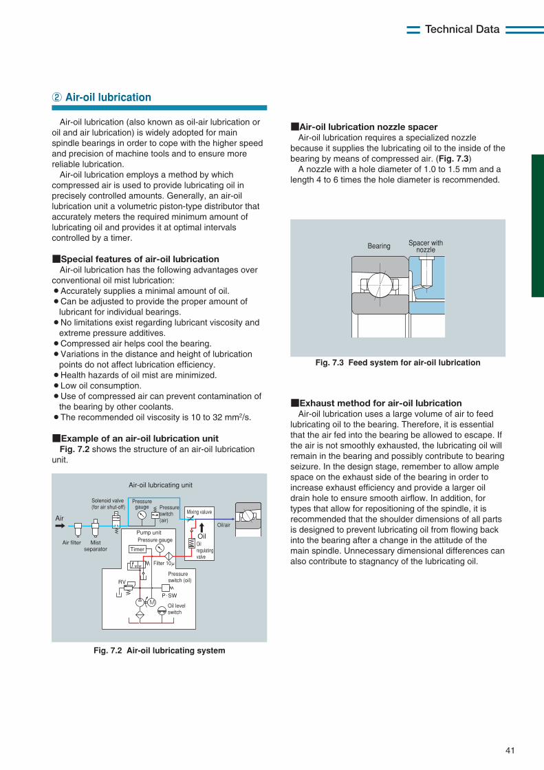
41
Technical Data
Air-oil lubrication (also known as oil-air lubrication oroil and air lubrication) is widely adopted for mainspindle bearings in order to cope with the higher speedand precision of machine tools and to ensure morereliable lubrication.
Air-oil lubrication employs a method by whichcompressed air is used to provide lubricating oil inprecisely controlled amounts. Generally, an air-oillubrication unit a volumetric piston-type distributor thataccurately meters the required minimum amount oflubricating oil and provides it at optimal intervalscontrolled by a timer.
■Special features of air-oil lubricationAir-oil lubrication has the following advantages over
conventional oil mist lubrication:¡Accurately supplies a minimal amount of oil.¡Can be adjusted to provide the proper amount of
lubricant for individual bearings.¡No limitations exist regarding lubricant viscosity and
extreme pressure additives. ¡Compressed air helps cool the bearing.¡Variations in the distance and height of lubrication
points do not affect lubrication efficiency.¡Health hazards of oil mist are minimized.¡Low oil consumption.¡Use of compressed air can prevent contamination of
the bearing by other coolants.¡The recommended oil viscosity is 10 to 32 mm2/s.
■Example of an air-oil lubrication unitFig. 7.2 shows the structure of an air-oil lubrication
unit.
■Air-oil lubrication nozzle spacerAir-oil lubrication requires a specialized nozzle
because it supplies the lubricating oil to the inside of thebearing by means of compressed air. (Fig. 7.3)
A nozzle with a hole diameter of 1.0 to 1.5 mm and alength 4 to 6 times the hole diameter is recommended.
② Air-oil lubrication
Air
Air-oil lubricating unit
Mist separator
Air filter
Air tank (level switch)
Pressure switch
Oil
Solenoid valveTimer
Air
Air-oil line
Nozzle
M
RV
Air filter
Air
Air-oil lubricating unit
Solenoid valve (for air shut-off)
Mist separator Timer
Pressure gauge
Filter 10μ
Oil level switch
P・SW
Pressure switch (oil)
Oil/air
Pressure switch (air)
Pressure gaugeOil regulating valve
Mixing valuve
Pump unitOil
Bearing Spacer with nozzle
Fig. 7.3 Feed system for air-oil lubrication
Fig. 7.2 Air-oil lubricating system
■Exhaust method for air-oil lubricationAir-oil lubrication uses a large volume of air to feed
lubricating oil to the bearing. Therefore, it is essentialthat the air fed into the bearing be allowed to escape. Ifthe air is not smoothly exhausted, the lubricating oil willremain in the bearing and possibly contribute to bearingseizure. In the design stage, remember to allow amplespace on the exhaust side of the bearing in order toincrease exhaust efficiency and provide a larger oildrain hole to ensure smooth airflow. In addition, fortypes that allow for repositioning of the spindle, it isrecommended that the shoulder dimensions of all partsis designed to prevent lubricating oil from flowing backinto the bearing after a change in the attitude of themain spindle. Unnecessary dimensional differences canalso contribute to stagnancy of the lubricating oil.
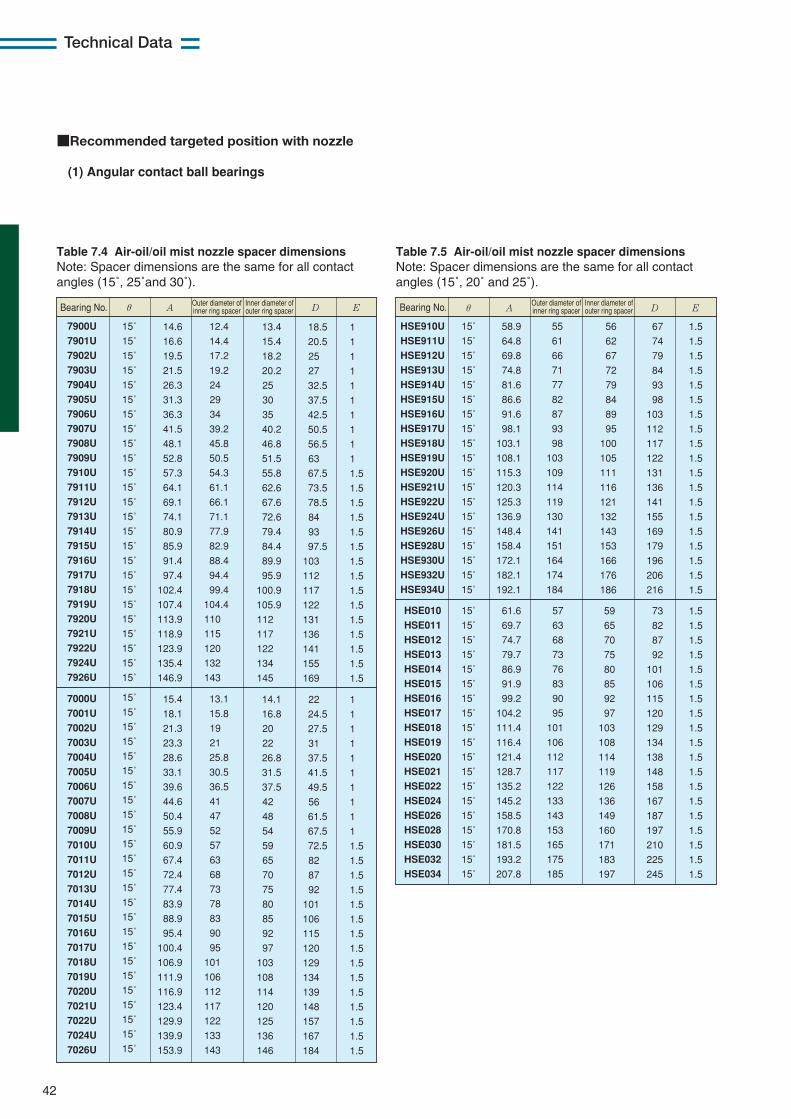
42
Technical Data
■Recommended targeted position with nozzle
(1) Angular contact ball bearings
Table 7.5 Air-oil/oil mist nozzle spacer dimensionsNote: Spacer dimensions are the same for all contactangles (15˚, 20˚ and 25˚).
HSE010
HSE011
HSE012
HSE013
HSE014
HSE015
HSE016
HSE017
HSE018
HSE019
HSE020
HSE021
HSE022
HSE024
HSE026
HSE028
HSE030
HSE032
HSE034
15˚
15˚
15˚
15˚
15˚
15˚
15˚
15˚
15˚
15˚
15˚
15˚
15˚
15˚
15˚
15˚
15˚
15˚
15˚
57
63
68
73
76
83
90
95
101
106
112
117
122
133
143
153
165
175
185
61.6
69.7
74.7
79.7
86.9
91.9
99.2
104.2
111.4
116.4
121.4
128.7
135.2
145.2
158.5
170.8
181.5
193.2
207.8
59
65
70
75
80
85
92
97
103
108
114
119
126
136
149
160
171
183
197
73
82
87
92
101
106
115
120
129
134
138
148
158
167
187
197
210
225
245
1.5
1.5
1.5
1.5
1.5
1.5
1.5
1.5
1.5
1.5
1.5
1.5
1.5
1.5
1.5
1.5
1.5
1.5
1.5
θ A D EBearing No. Outer diameter of inner ring spacer
Inner diameter of outer ring spacer
HSE910U
HSE911U
HSE912U
HSE913U
HSE914U
HSE915U
HSE916U
HSE917U
HSE918U
HSE919U
HSE920U
HSE921U
HSE922U
HSE924U
HSE926U
HSE928U
HSE930U
HSE932U
HSE934U
15˚
15˚
15˚
15˚
15˚
15˚
15˚
15˚
15˚
15˚
15˚
15˚
15˚
15˚
15˚
15˚
15˚
15˚
15˚
55
61
66
71
77
82
87
93
98
103
109
114
119
130
141
151
164
174
184
58.9
64.8
69.8
74.8
81.6
86.6
91.6
98.1
103.1
108.1
115.3
120.3
125.3
136.9
148.4
158.4
172.1
182.1
192.1
56
62
67
72
79
84
89
95
100
105
111
116
121
132
143
153
166
176
186
67
74
79
84
93
98
103
112
117
122
131
136
141
155
169
179
196
206
216
1.5
1.5
1.5
1.5
1.5
1.5
1.5
1.5
1.5
1.5
1.5
1.5
1.5
1.5
1.5
1.5
1.5
1.5
1.5
Table 7.4 Air-oil/oil mist nozzle spacer dimensionsNote: Spacer dimensions are the same for all contactangles (15˚, 25˚and 30˚).
7900U
7901U
7902U
7903U
7904U
7905U
7906U
7907U
7908U
7909U
7910U
7911U
7912U
7913U
7914U
7915U
7916U
7917U
7918U
7919U
7920U
7921U
7922U
7924U
7926U
7000U
7001U
7002U
7003U
7004U
7005U
7006U
7007U
7008U
7009U
7010U
7011U
7012U
7013U
7014U
7015U
7016U
7017U
7018U
7019U
7020U
7021U
7022U
7024U
7026U
15˚
15˚
15˚
15˚
15˚
15˚
15˚
15˚
15˚
15˚
15˚
15˚
15˚
15˚
15˚
15˚
15˚
15˚
15˚
15˚
15˚
15˚
15˚
15˚
15˚
15˚
15˚
15˚
15˚
15˚
15˚
15˚
15˚
15˚
15˚
15˚
15˚
15˚
15˚
15˚
15˚
15˚
15˚
15˚
15˚
15˚
15˚
15˚
15˚
15˚
12.4
14.4
17.2
19.2
24
29
34
39.2
45.8
50.5
54.3
61.1
66.1
71.1
77.9
82.9
88.4
94.4
99.4
104.4
110
115
120
132
143
13.1
15.8
19
21
25.8
30.5
36.5
41
47
52
57
63
68
73
78
83
90
95
101
106
112
117
122
133
143
14.6
16.6
19.5
21.5
26.3
31.3
36.3
41.5
48.1
52.8
57.3
64.1
69.1
74.1
80.9
85.9
91.4
97.4
102.4
107.4
113.9
118.9
123.9
135.4
146.9
15.4
18.1
21.3
23.3
28.6
33.1
39.6
44.6
50.4
55.9
60.9
67.4
72.4
77.4
83.9
88.9
95.4
100.4
106.9
111.9
116.9
123.4
129.9
139.9
153.9
13.4
15.4
18.2
20.2
25
30
35
40.2
46.8
51.5
55.8
62.6
67.6
72.6
79.4
84.4
89.9
95.9
100.9
105.9
112
117
122
134
145
14.1
16.8
20
22
26.8
31.5
37.5
42
48
54
59
65
70
75
80
85
92
97
103
108
114
120
125
136
146
18.5
20.5
25
27
32.5
37.5
42.5
50.5
56.5
63
67.5
73.5
78.5
84
93
97.5
103
112
117
122
131
136
141
155
169
22
24.5
27.5
31
37.5
41.5
49.5
56
61.5
67.5
72.5
82
87
92
101
106
115
120
129
134
139
148
157
167
184
1
1
1
1
1
1
1
1
1
1
1.5
1.5
1.5
1.5
1.5
1.5
1.5
1.5
1.5
1.5
1.5
1.5
1.5
1.5
1.5
1
1
1
1
1
1
1
1
1
1
1.5
1.5
1.5
1.5
1.5
1.5
1.5
1.5
1.5
1.5
1.5
1.5
1.5
1.5
1.5
Bearing No. θ A D EOuter diameter of inner ring spacer
Inner diameter of outer ring spacer
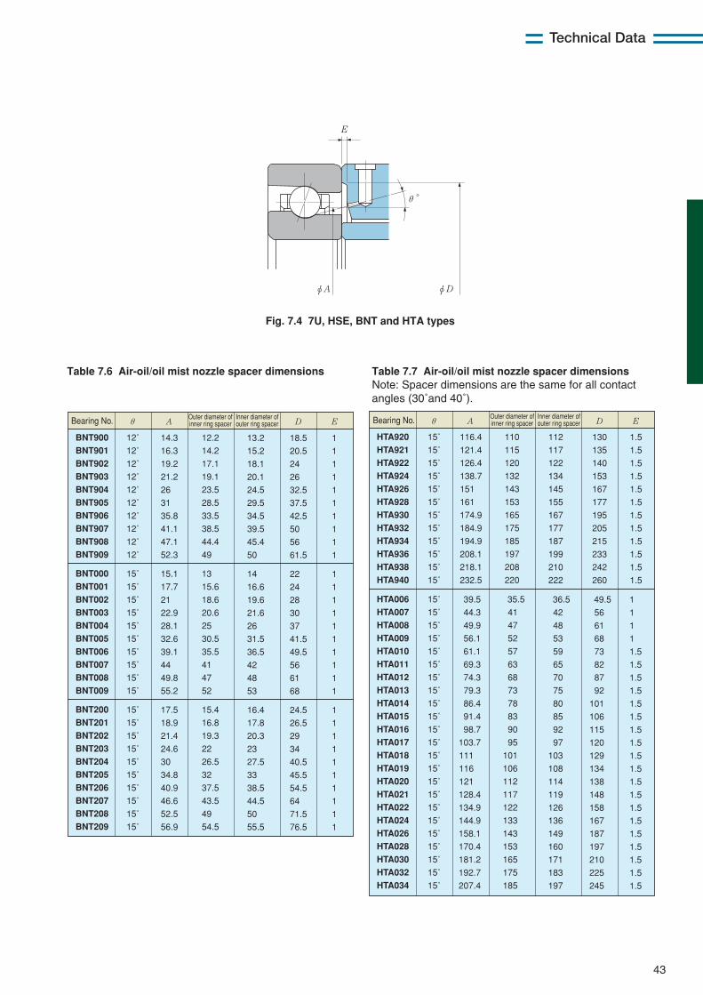
E
φDφA
θ°
43
Technical Data
Fig. 7.4 7U, HSE, BNT and HTA types
Table 7.7 Air-oil/oil mist nozzle spacer dimensionsNote: Spacer dimensions are the same for all contactangles (30˚and 40˚).
HTA920
HTA921
HTA922
HTA924
HTA926
HTA928
HTA930
HTA932
HTA934
HTA936
HTA938
HTA940
15˚
15˚
15˚
15˚
15˚
15˚
15˚
15˚
15˚
15˚
15˚
15˚
110
115
120
132
143
153
165
175
185
197
208
220
116.4
121.4
126.4
138.7
151
161
174.9
184.9
194.9
208.1
218.1
232.5
112
117
122
134
145
155
167
177
187
199
210
222
130
135
140
153
167
177
195
205
215
233
242
260
1.5
1.5
1.5
1.5
1.5
1.5
1.5
1.5
1.5
1.5
1.5
1.5
HTA006
HTA007
HTA008
HTA009
HTA010
HTA011
HTA012
HTA013
HTA014
HTA015
HTA016
HTA017
HTA018
HTA019
HTA020
HTA021
HTA022
HTA024
HTA026
HTA028
HTA030
HTA032
HTA034
15˚
15˚
15˚
15˚
15˚
15˚
15˚
15˚
15˚
15˚
15˚
15˚
15˚
15˚
15˚
15˚
15˚
15˚
15˚
15˚
15˚
15˚
15˚
35.5
41
47
52
57
63
68
73
78
83
90
95
101
106
112
117
122
133
143
153
165
175
185
39.5
44.3
49.9
56.1
61.1
69.3
74.3
79.3
86.4
91.4
98.7
103.7
111
116
121
128.4
134.9
144.9
158.1
170.4
181.2
192.7
207.4
36.5
42
48
53
59
65
70
75
80
85
92
97
103
108
114
119
126
136
149
160
171
183
197
49.5
56
61
68
73
82
87
92
101
106
115
120
129
134
138
148
158
167
187
197
210
225
245
1
1
1
1
1.5
1.5
1.5
1.5
1.5
1.5
1.5
1.5
1.5
1.5
1.5
1.5
1.5
1.5
1.5
1.5
1.5
1.5
1.5
θ A D EBearing No. Outer diameter of inner ring spacer
Inner diameter of outer ring spacer
Table 7.6 Air-oil/oil mist nozzle spacer dimensions
BNT900
BNT901
BNT902
BNT903
BNT904
BNT905
BNT906
BNT907
BNT908
BNT909
BNT000
BNT001
BNT002
BNT003
BNT004
BNT005
BNT006
BNT007
BNT008
BNT009
BNT200
BNT201
BNT202
BNT203
BNT204
BNT205
BNT206
BNT207
BNT208
BNT209
12˚
12˚
12˚
12˚
12˚
12˚
12˚
12˚
12˚
12˚
15˚
15˚
15˚
15˚
15˚
15˚
15˚
15˚
15˚
15˚
15˚
15˚
15˚
15˚
15˚
15˚
15˚
15˚
15˚
15˚
12.2
14.2
17.1
19.1
23.5
28.5
33.5
38.5
44.4
49
13
15.6
18.6
20.6
25
30.5
35.5
41
47
52
15.4
16.8
19.3
22
26.5
32
37.5
43.5
49
54.5
14.3
16.3
19.2
21.2
26
31
35.8
41.1
47.1
52.3
15.1
17.7
21
22.9
28.1
32.6
39.1
44
49.8
55.2
17.5
18.9
21.4
24.6
30
34.8
40.9
46.6
52.5
56.9
13.2
15.2
18.1
20.1
24.5
29.5
34.5
39.5
45.4
50
14
16.6
19.6
21.6
26
31.5
36.5
42
48
53
16.4
17.8
20.3
23
27.5
33
38.5
44.5
50
55.5
18.5
20.5
24
26
32.5
37.5
42.5
50
56
61.5
22
24
28
30
37
41.5
49.5
56
61
68
24.5
26.5
29
34
40.5
45.5
54.5
64
71.5
76.5
1
1
1
1
1
1
1
1
1
1
1
1
1
1
1
1
1
1
1
1
1
1
1
1
1
1
1
1
1
1
θ A D EBearing No. Outer diameter of inner ring spacer
Inner diameter of outer ring spacer
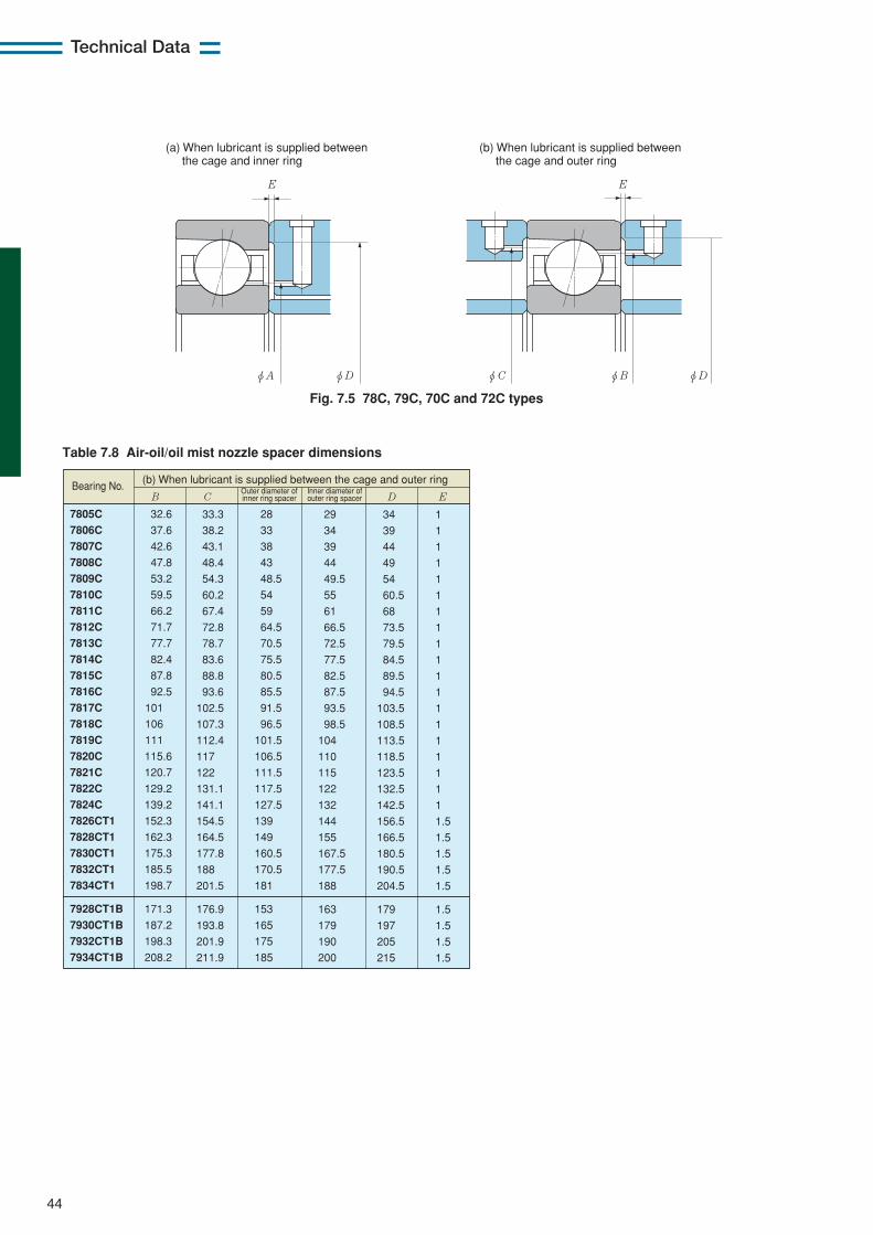
44
Technical Data
φDφBφDφA φC
EE
(a) When lubricant is supplied between the cage and inner ring
(b) When lubricant is supplied between the cage and outer ring
Fig. 7.5 78C, 79C, 70C and 72C types
Table 7.8 Air-oil/oil mist nozzle spacer dimensions
7805C
7806C
7807C
7808C
7809C
7810C
7811C
7812C
7813C
7814C
7815C
7816C
7817C
7818C
7819C
7820C
7821C
7822C
7824C
7826CT1
7828CT1
7830CT1
7832CT1
7834CT1
7928CT1B
7930CT1B
7932CT1B
7934CT1B
32.6
37.6
42.6
47.8
53.2
59.5
66.2
71.7
77.7
82.4
87.8
92.5
101
106
111
115.6
120.7
129.2
139.2
152.3
162.3
175.3
185.5
198.7
171.3
187.2
198.3
208.2
28
33
38
43
48.5
54
59
64.5
70.5
75.5
80.5
85.5
91.5
96.5
101.5
106.5
111.5
117.5
127.5
139
149
160.5
170.5
181
153
165
175
185
33.3
38.2
43.1
48.4
54.3
60.2
67.4
72.8
78.7
83.6
88.8
93.6
102.5
107.3
112.4
117
122
131.1
141.1
154.5
164.5
177.8
188
201.5
176.9
193.8
201.9
211.9
29
34
39
44
49.5
55
61
66.5
72.5
77.5
82.5
87.5
93.5
98.5
104
110
115
122
132
144
155
167.5
177.5
188
163
179
190
200
34
39
44
49
54
60.5
68
73.5
79.5
84.5
89.5
94.5
103.5
108.5
113.5
118.5
123.5
132.5
142.5
156.5
166.5
180.5
190.5
204.5
179
197
205
215
1
1
1
1
1
1
1
1
1
1
1
1
1
1
1
1
1
1
1
1.5
1.5
1.5
1.5
1.5
1.5
1.5
1.5
1.5
(b) When lubricant is supplied between the cage and outer ring
B C D EBearing No. Outer diameter of
inner ring spacer
Inner diameter of outer ring spacer
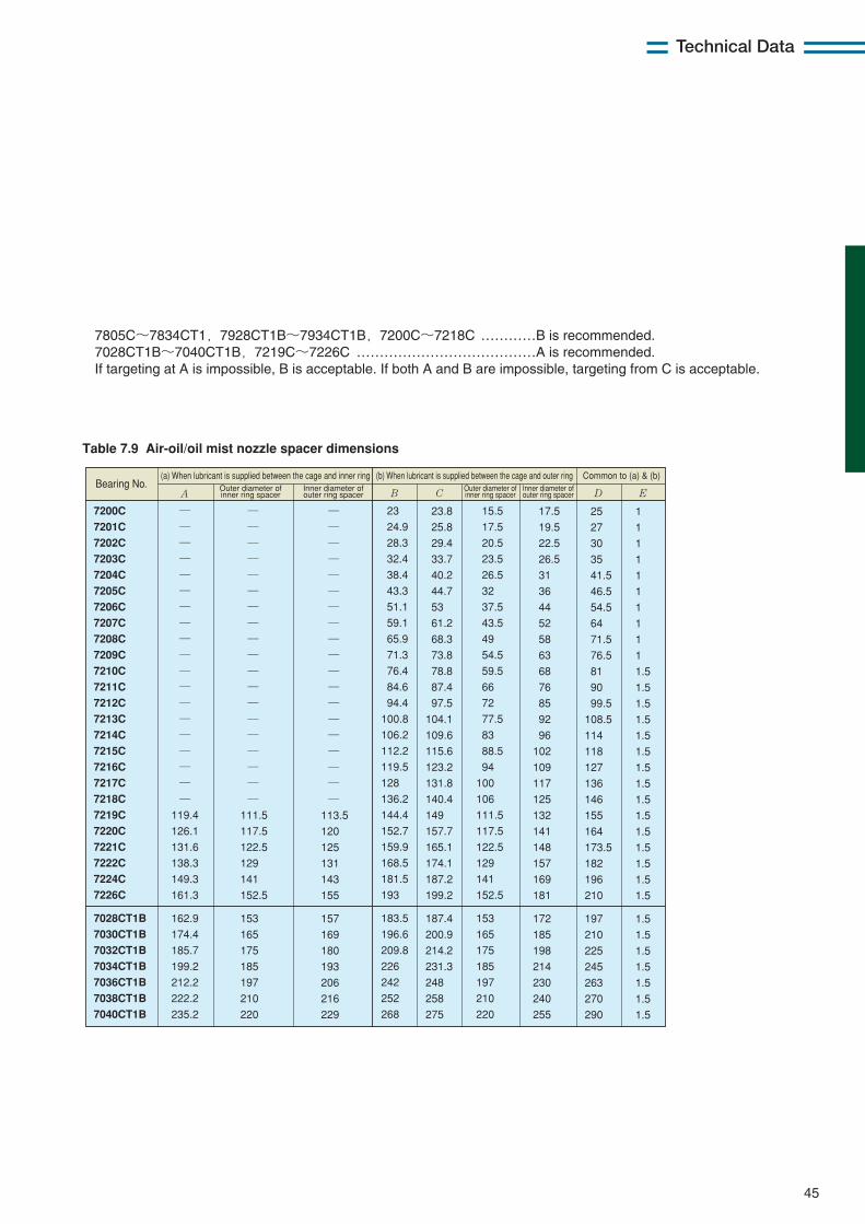
45
Technical Data
Table 7.9 Air-oil/oil mist nozzle spacer dimensions
23
24.9
28.3
32.4
38.4
43.3
51.1
59.1
65.9
71.3
76.4
84.6
94.4
100.8
106.2
112.2
119.5
128
136.2
144.4
152.7
159.9
168.5
181.5
193
183.5
196.6
209.8
226
242
252
268
15.5
17.5
20.5
23.5
26.5
32
37.5
43.5
49
54.5
59.5
66
72
77.5
83
88.5
94
100
106
111.5
117.5
122.5
129
141
152.5
153
165
175
185
197
210
220
23.8
25.8
29.4
33.7
40.2
44.7
53
61.2
68.3
73.8
78.8
87.4
97.5
104.1
109.6
115.6
123.2
131.8
140.4
149
157.7
165.1
174.1
187.2
199.2
187.4
200.9
214.2
231.3
248
258
275
17.5
19.5
22.5
26.5
31
36
44
52
58
63
68
76
85
92
96
102
109
117
125
132
141
148
157
169
181
172
185
198
214
230
240
255
25
27
30
35
41.5
46.5
54.5
64
71.5
76.5
81
90
99.5
108.5
114
118
127
136
146
155
164
173.5
182
196
210
197
210
225
245
263
270
290
1
1
1
1
1
1
1
1
1
1
1.5
1.5
1.5
1.5
1.5
1.5
1.5
1.5
1.5
1.5
1.5
1.5
1.5
1.5
1.5
1.5
1.5
1.5
1.5
1.5
1.5
1.5
(b) When lubricant is supplied between the cage and outer ring Common to (a) & (b)
B C D E
7200C
7201C
7202C
7203C
7204C
7205C
7206C
7207C
7208C
7209C
7210C
7211C
7212C
7213C
7214C
7215C
7216C
7217C
7218C
7219C
7220C
7221C
7222C
7224C
7226C
7028CT1B
7030CT1B
7032CT1B
7034CT1B
7036CT1B
7038CT1B
7040CT1B
―
―
―
―
―
―
―
―
―
―
―
―
―
―
―
―
―
―
―
119.4
126.1
131.6
138.3
149.3
161.3
162.9
174.4
185.7
199.2
212.2
222.2
235.2
―
―
―
―
―
―
―
―
―
―
―
―
―
―
―
―
―
―
―
111.5
117.5
122.5
129
141
152.5
153
165
175
185
197
210
220
―
―
―
―
―
―
―
―
―
―
―
―
―
―
―
―
―
―
―
113.5
120
125
131
143
155
157
169
180
193
206
216
229
ABearing No. Outer diameter of
inner ring spacer
Inner diameter of outer ring spacer
Outer diameter of inner ring spacer
Inner diameter of outer ring spacer
(a) When lubricant is supplied between the cage and inner ring
7805C〜7834CT1,7928CT1B〜7934CT1B,7200C〜7218C …………B is recommended.7028CT1B〜7040CT1B,7219C〜7226C …………………………………A is recommended.If targeting at A is impossible, B is acceptable. If both A and B are impossible, targeting from C is acceptable.
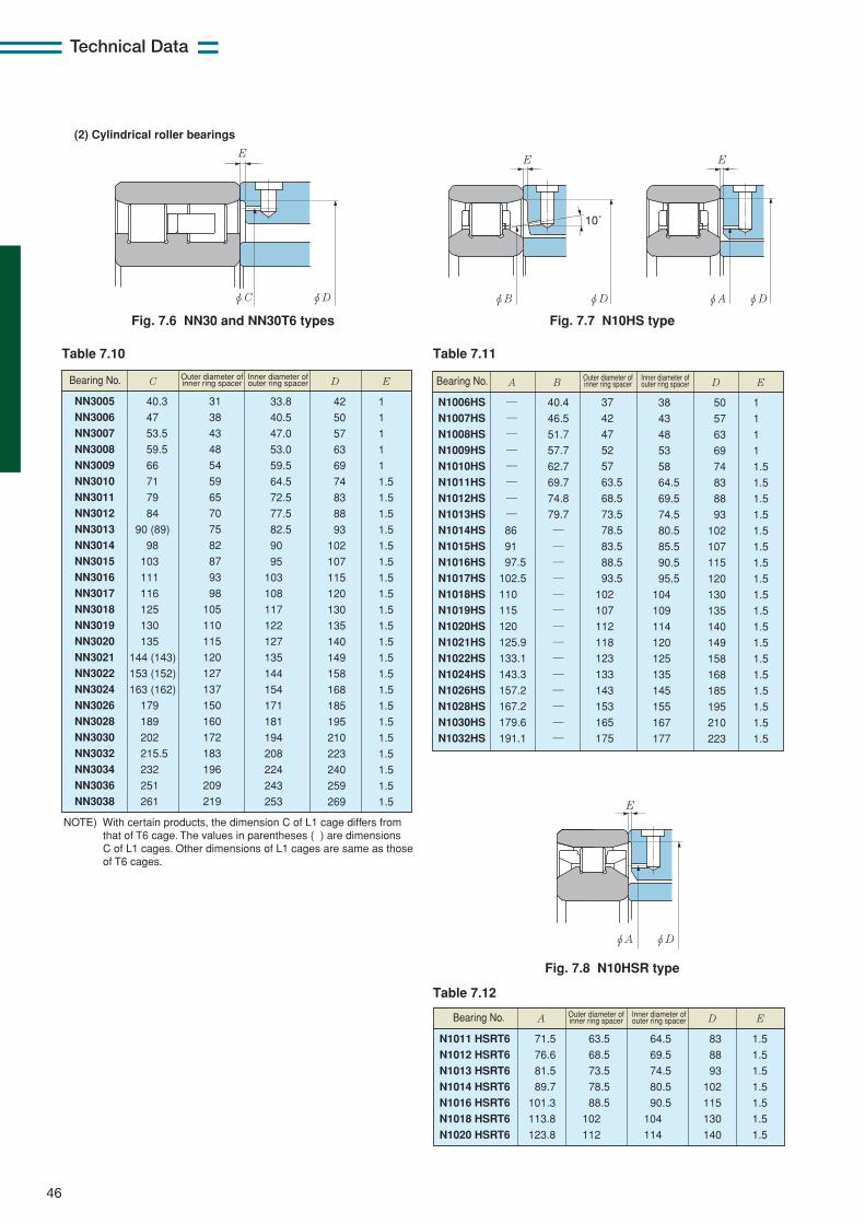
46
Technical Data
φDφC
E
(2) Cylindrical roller bearings
Fig. 7.6 NN30 and NN30T6 types Fig. 7.7 N10HS type
Table 7.10 Table 7.11
NN3005
NN3006
NN3007
NN3008
NN3009
NN3010
NN3011
NN3012
NN3013
NN3014
NN3015
NN3016
NN3017
NN3018
NN3019
NN3020
NN3021
NN3022
NN3024
NN3026
NN3028
NN3030
NN3032
NN3034
NN3036
NN3038
31
38
43
48
54
59
65
70
75
82
87
93
98
105
110
115
120
127
137
150
160
172
183
196
209
219
40.3
47
53.5
59.5
66
71
79
84
90 (89)
98
103
111
116
125
130
135
144 (143)
153 (152)
163 (162)
179
189
202
215.5
232
251
261
33.8
40.5
47.0
53.0
59.5
64.5
72.5
77.5
82.5
90
95
103
108
117
122
127
135
144
154
171
181
194
208
224
243
253
42
50
57
63
69
74
83
88
93
102
107
115
120
130
135
140
149
158
168
185
195
210
223
240
259
269
1
1
1
1
1
1.5
1.5
1.5
1.5
1.5
1.5
1.5
1.5
1.5
1.5
1.5
1.5
1.5
1.5
1.5
1.5
1.5
1.5
1.5
1.5
1.5
C D EBearing No. Outer diameter of inner ring spacer
Inner diameter of outer ring spacer
NOTE) With certain products, the dimension C of L1 cage differs from that of T6 cage. The values in parentheses ( ) are dimensions C of L1 cages. Other dimensions of L1 cages are same as those of T6 cages.
N1006HS
N1007HS
N1008HS
N1009HS
N1010HS
N1011HS
N1012HS
N1013HS
N1014HS
N1015HS
N1016HS
N1017HS
N1018HS
N1019HS
N1020HS
N1021HS
N1022HS
N1024HS
N1026HS
N1028HS
N1030HS
N1032HS
―
―
―
―
―
―
―
―
86
91
97.5
102.5
110
115
120
125.9
133.1
143.3
157.2
167.2
179.6
191.1
37
42
47
52
57
63.5
68.5
73.5
78.5
83.5
88.5
93.5
102
107
112
118
123
133
143
153
165
175
40.4
46.5
51.7
57.7
62.7
69.7
74.8
79.7
―
―
―
―
―
―
―
―
―
―
―
―
―
―
38
43
48
53
58
64.5
69.5
74.5
80.5
85.5
90.5
95.5
104
109
114
120
125
135
145
155
167
177
50
57
63
69
74
83
88
93
102
107
115
120
130
135
140
149
158
168
185
195
210
223
1
1
1
1
1.5
1.5
1.5
1.5
1.5
1.5
1.5
1.5
1.5
1.5
1.5
1.5
1.5
1.5
1.5
1.5
1.5
1.5
A B D EBearing No. Outer diameter of inner ring spacer
Inner diameter of outer ring spacer
Table 7.12
N1011 HSRT6
N1012 HSRT6
N1013 HSRT6
N1014 HSRT6
N1016 HSRT6
N1018 HSRT6
N1020 HSRT6
63.5
68.5
73.5
78.5
88.5
102
112
71.5
76.6
81.5
89.7
101.3
113.8
123.8
64.5
69.5
74.5
80.5
90.5
104
114
83
88
93
102
115
130
140
1.5
1.5
1.5
1.5
1.5
1.5
1.5
A D EBearing No. Outer diameter of inner ring spacer
Inner diameter of outer ring spacer
φA φD
EE
φDφB
10˚
Fig. 7.8 N10HSR type
φA φDφDφB
E
10˚

47
Technical Data
With this lubricating system, a high-speed jet oflubricant is injected into the bearing from the side. Thisis the most reliable lubricating technique and is typicallyused on the main spindle bearings of jet engines andgas turbines. It is currently capable of a dmn value of upto approximately 4.0×10⁶.
When used as a lubricating system for the mainspindle of a machine tool, it can minimize thetemperature increase of the bearing. However, the
③ Jet lubrication
Bearing : 2LA-HSE020, bore 100 mm, outside diameter 150 mm Rolling element : Bearing steel
Tem
pera
ture
incr
ease
on
oute
r rin
g ˚
C
Air-oil (Oil volume: 0.03 mL/min, air: 75 NL/min)
Jet (Oil volume: 3.1L/min)
Speed min-1
dmn value ×106
60
50
40
30
5000 10000 15000 20000
20
10
0
1.25 2.5
Speed min-150000
4
3
2
1
10000 15000 20000
Bearing : 2LA-HSE020, bore 100 mm, outside diameter 150 mm Rolling element : Bearing steel
Pow
er lo
ss k
W /
bear
ing
Jet (Oil volume: 3.1L/min)
Air-oil (Oil volume: 0.03 mL/min air: 75 NL/min)
dmn value ×106
1.25 2.5
Fig. 7.10 Comparison of power loss with air-oillubrication and with jet lubrication
Fig. 7.9 Comparison of temperature increase of outerring with air-oil lubrication and jet lubrication
(The temperature increase with air-oil lubrication is relative toroom temperature; the temperature with jet lubrication is relative tolubricant temperature.)
resultant torque loss is great, as a large amount of oil issupplied to each bearing. Therefore, this arrangementrequires a powerful motor to drive the main spindle.Low viscosity oil (2-3 mm2/s) is used.Fig. 7.9 shows examples of the temperature increase
with air-oil lubrication and jet lubrication, while Fig. 7.10graphically plots test results of power loss.
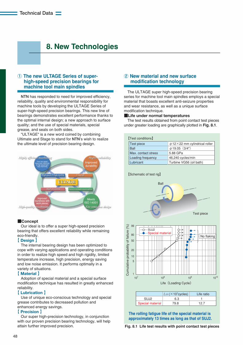
48
Technical Data
8. New Technologies
NTN has responded to need for improved efficiency,reliability, quality and environmental responsibility formachine tools by developing the ULTAGE Series ofsuper-high-speed precision bearings. This new line ofbearings demonstrates excellent performance thanks tothe optimal internal design; a new approach to surfacequality; and the use of special materials, specialgrease, and seals on both sides.
"ULTAGE" is a new word coined by combiningUltimate and Stage to stand for NTN’s wish to realizethe ultimate level of precision bearing design.
The ULTAGE super high-speed precision bearingseries for machine tool main spindles employs a specialmaterial that boasts excellent anti-seizure propertiesand wear resistance, as well as a unique surfacemodification technique.■Life under normal temperatures
The test results obtained from point contact test piecesunder greater loading are graphically plotted in Fig. 8.1.
① The new ULTAGE Series of super-high-speed precision bearings for machine tool main spindles
Improved roundness with
work pieces
From low-speed heavy-duty machining
to high-speed light -duty machining
Improved durability
Meets ISO 14001
■ConceptOur ideal is to offer a super high-speed precision
bearing that offers excellent reliability while remainingeco-friendly.
【 Design 】The internal bearing design has been optimized to
cope with varying applications and operating conditionsin order to realize high speed and high rigidity, limitedtemperature increase, high precision, energy savingand low noise emission. It performs optimally in avariety of situations.
【 Material 】Adoption of special material and a special surface
modification technique has resulted in greatly enhancedreliability.
【 Lubrication 】Use of unique eco-conscious technology and special
grease contributes to decreased pollution andenhanced energy savings.【 Precision 】
Our super high-precision technology, in conjunctionwith our proven precision bearing technology, will helpattain further improved precision.
② New material and new surface modification technology
Fig. 8.1 Life test results with point contact test pieces
【Schematic of test rig】
SUJ2
No flakingSpecial material
107 108 109 10101
5
10
50
80
99
20
Life(Loading Cycle)
Cum
ulat
ive
prob
abili
ty o
f fai
lure
(%
)
Ball
Test piece
Test piece Ball Max. contact stress Loading frequency Lubricant
φ12×22 mm cylindrical roller φ19.05(3/4") 5.88 GPa 46,240 cycles/min Turbine VG56 (oil bath)
【Test conditions】
SUJ2Special material
6.379.8
112.7
Life ratioL10 (×107cycles)
The rolling fatigue life of the special material is approximately 13 times as long as that of SUJ2.

49
Technical Data
■Life under high temperatureThe test results obtained from thrust-type test pieces
at 200˚C are graphically plotted in Fig. 8.2.
■ Improved wear resistanceTest results with a Sawin type friction and wear test
machine are illustrated in Fig. 8.3.
Fig. 8.2 High temperature life test results with thrust-type test pieces
【Test conditions】
【Schematic of test rig】
SUJ2
No flaking
Special material
105 106 107 1081
5
10
50
80
99
20
Life (loading cycles)
Cum
ulat
ive
prob
abili
ty o
f fai
lure
(%
)
Ceramic ball
Test piece (flat plate)
Test piece Ball Max. contact stress Loading frequency Oil temperature Lubricant
φ47×φ29×t7 flat plate φ6.35(1/4")Ceramic ball 5.5 GPa 3,000 cycles/min 200˚C Ether-based oil
SUJ2Special material
9.1No flaking
1>30
Life ratioL10 (×105cycles)
The rolling fatigue life of the special material at a high temperature of 200˚C is more than 30 times as long as that of SUJ2.
Fig. 8.3 Test results with Sawin type friction and weartest machine
The wear resistance of the special material is 6 times better than that with SUJ2.
【Test conditions】 【Schematic of test rig】
SUJ2 144×10-6 mm3
Amount of wear
23×10-6 mm3Special material
Rotating test piece
Fixed test piece
Speed Peripheral speed Test duration Max. contact stress Lubricant Rotating test piece Fixed test piece
4775 min-1 10 m/s 10 min 2.0 GPa VG2 Material being tested Si3N4
■ Improved anti-seizure propertyTest results with a two roller testing machine are
illustrated in Fig. 8.4.
Fig. 8.4 Test results with a two roller testing machine
The anti-seizure property of the special material is more than 15 times better than as that with SUJ2.
【Test conditions】 【Schematic of test rig】
Driven roller
Driving roller
SUJ2
Duration
3000 min or longer
200min
Special material
Driving side speed Driven side speed Sliding velocity Max. contact stress Lubricant Driving roller Driven roller
200 min-1 120 min-1 10.1 m/s 2.9 GPa VG2 Material being tested Material being tested
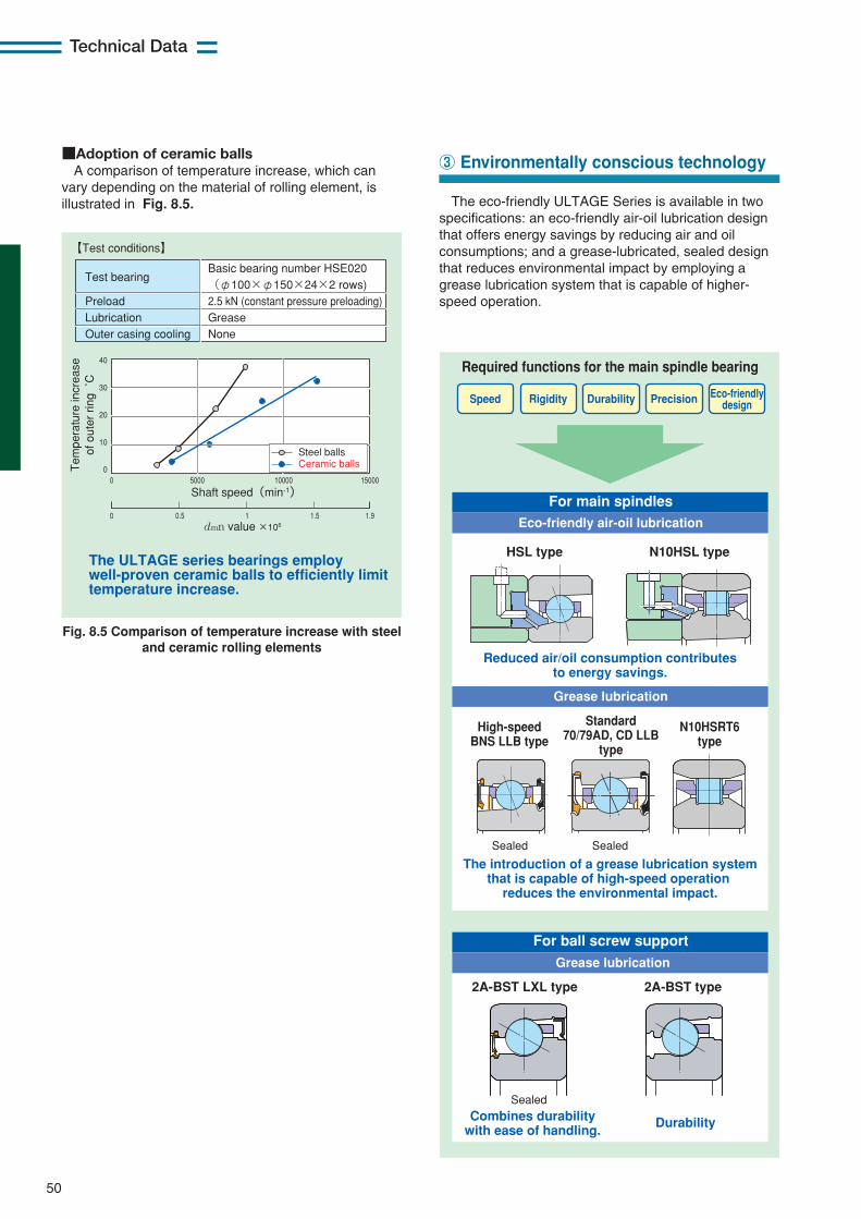
50
Technical Data
■Adoption of ceramic ballsA comparison of temperature increase, which can
vary depending on the material of rolling element, isillustrated in Fig. 8.5.
Fig. 8.5 Comparison of temperature increase with steeland ceramic rolling elements
The ULTAGE series bearings employ well-proven ceramic balls to efficiently limit temperature increase.
【Test conditions】
0
0 0.5 1 1.5 1.9
5000 10000 15000
40
30
20
10
0
Shaft speed(min-1)
dmn value ×106
Tem
pera
ture
incr
ease
of
out
er r
ing
˚C
Steel balls Ceramic balls
Test bearing Preload Lubrication Outer casing cooling
Basic bearing number HSE020 (φ100×φ150×24×2 rows) 2.5 kN (constant pressure preloading) Grease None
The eco-friendly ULTAGE Series is available in twospecifications: an eco-friendly air-oil lubrication designthat offers energy savings by reducing air and oilconsumptions; and a grease-lubricated, sealed designthat reduces environmental impact by employing agrease lubrication system that is capable of higher-speed operation.
③ Environmentally conscious technology
Required functions for the main spindle bearing
Speed Rigidity Durability Precision Eco-friendly design
For main spindles
Eco-friendly air-oil lubrication
For ball screw support
Grease lubrication
Grease lubrication
HSL type N10HSL type
Reduced air/oil consumption contributes to energy savings.
Sealed
Sealed
Sealed
The introduction of a grease lubrication system that is capable of high-speed operation
reduces the environmental impact.
High-speed BNS LLB type
N10HSRT6 type
Standard 70/79AD, CD LLB
type
2A-BST LXL type 2A-BST type
Combines durability with ease of handling.
Durability

51
Technical Data
Table 8.1 Bearing combinations and seal colors
■ Grease-lubricated sealed angular contact ball bearings(1) Ease of handling
ULTAGE angular contact ball bearings with seals are grease-prefilled bearings. No grease filling is necessary; youneed only wipe off the rust-preventive oil before assembly. Seals of different colors are employed to differentiate thefront and back. The black front face and orange back face are easily identified, which also makes it easy to orient thebearings in combinations (Table 8.1).
(2) Suggestions for simplified spindle structureThe ULTAGE Series sealed angular contact ball bearing makes possible high-speed operation with grease
lubrication thanks to optimized internal design. Grease lubrication with minimal mist splash simplifies main spindlestructure and contributes to lower environmental impact as well as cost reduction (Fig. 8.6).
DB set (back-to-back)
+
DF set (face-to-face)
Orange seal Orange seal + Black seal Black seal
Fig. 8.6 Alteration to lubrication system (air-oil lubrication to grease lubrication)
Simplifies the main spindle structure and reduces both the initial cost and operating cost.
Air-oil lubrication Grease lubrication
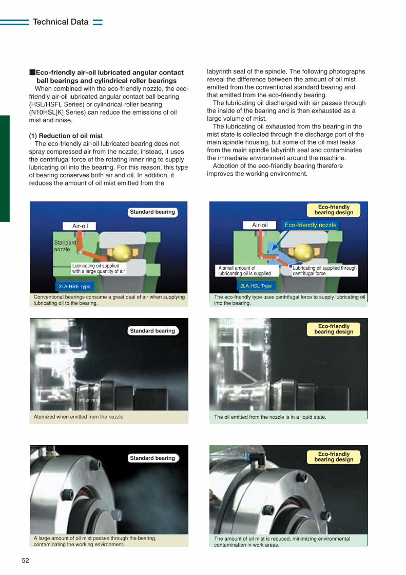
52
Technical Data
■Eco-friendly air-oil lubricated angular contact ball bearings and cylindrical roller bearingsWhen combined with the eco-friendly nozzle, the eco-
friendly air-oil lubricated angular contact ball bearing(HSL/HSFL Series) or cylindrical roller bearing(N10HSL[K] Series) can reduce the emissions of oilmist and noise.
(1) Reduction of oil mistThe eco-friendly air-oil lubricated bearing does not
spray compressed air from the nozzle; instead, it usesthe centrifugal force of the rotating inner ring to supplylubricating oil into the bearing. For this reason, this typeof bearing conserves both air and oil. In addition, itreduces the amount of oil mist emitted from the
Eco-friendly bearing design
Eco-friendly bearing design
Eco-friendly bearing design
Air-oil Air-oil Eco-friendly nozzle
Conventional bearings consume a great deal of air when supplying lubricating oil to the bearing.
Standard nozzle
Inner ring
Lubricating oil supplied with a large quantity of air
A small amount of lubricanting oil is supplied
Lubricating oil supplied through centrifugal force
2LA-HSE type 2LA-HSL Type
The eco-friendly type uses centrifugal force to supply lubricating oil into the bearing.
The oil emitted from the nozzle is in a liquid state.
The amount of oil mist is reduced, minimizing environmental contamination in work areas.
Atomized when emitted from the nozzle
A large amount of oil mist passes through the bearing, contaminating the working environment.
Standard bearing
Standard bearing
Standard bearing
labyrinth seal of the spindle. The following photographsreveal the difference between the amount of oil mistemitted from the conventional standard bearing andthat emitted from the eco-friendly bearing.
The lubricating oil discharged with air passes throughthe inside of the bearing and is then exhausted as alarge volume of mist.
The lubricating oil exhausted from the bearing in themist state is collected through the discharge port of themain spindle housing, but some of the oil mist leaksfrom the main spindle labyrinth seal and contaminatesthe immediate environment around the machine.
Adoption of the eco-friendly bearing thereforeimproves the working environment.
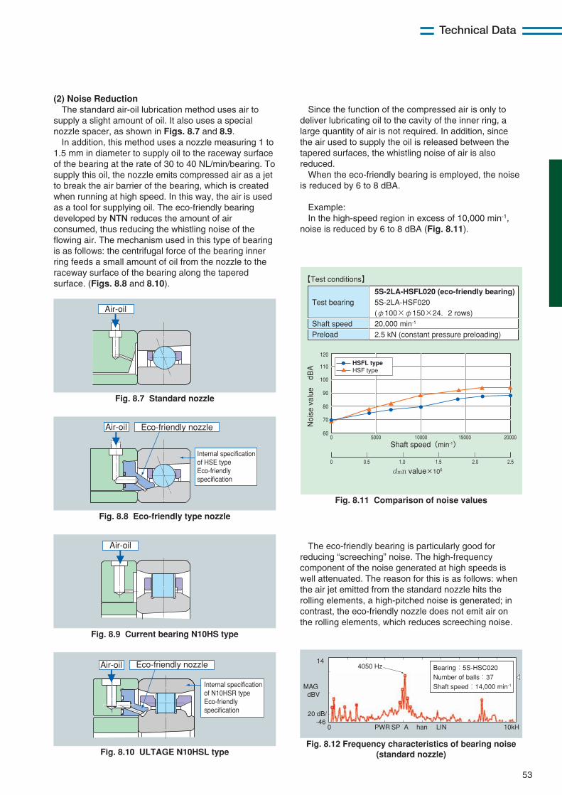
53
Technical Data
(2) Noise ReductionThe standard air-oil lubrication method uses air to
supply a slight amount of oil. It also uses a specialnozzle spacer, as shown in Figs. 8.7 and 8.9.
In addition, this method uses a nozzle measuring 1 to1.5 mm in diameter to supply oil to the raceway surfaceof the bearing at the rate of 30 to 40 NL/min/bearing. Tosupply this oil, the nozzle emits compressed air as a jetto break the air barrier of the bearing, which is createdwhen running at high speed. In this way, the air is usedas a tool for supplying oil. The eco-friendly bearingdeveloped by NTN reduces the amount of airconsumed, thus reducing the whistling noise of theflowing air. The mechanism used in this type of bearingis as follows: the centrifugal force of the bearing innerring feeds a small amount of oil from the nozzle to theraceway surface of the bearing along the taperedsurface. (Figs. 8.8 and 8.10).
Fig. 8.7 Standard nozzle
Air-oil
Fig. 8.8 Eco-friendly type nozzle
Air-oil Eco-friendly nozzle
Internal specification of HSE type Eco-friendly specification
Fig. 8.9 Current bearing N10HS type
Air-oil
Fig. 8.10 ULTAGE N10HSL type
Air-oil Eco-friendly nozzle
Internal specification of N10HSR type Eco-friendly specification
Since the function of the compressed air is only todeliver lubricating oil to the cavity of the inner ring, alarge quantity of air is not required. In addition, sincethe air used to supply the oil is released between thetapered surfaces, the whistling noise of air is alsoreduced.
When the eco-friendly bearing is employed, the noiseis reduced by 6 to 8 dBA.
Example:In the high-speed region in excess of 10,000 min-1,
noise is reduced by 6 to 8 dBA (Fig. 8.11).
Fig. 8.11 Comparison of noise values
Fig. 8.12 Frequency characteristics of bearing noise(standard nozzle)
0
0 0.5 1.0 1.5 2.0 2.5
5000 10000 200001500060
70
80
90
100
110
120
Shaft speed(min-1)
dmn value×106
Noi
se v
alue
dBA
【Test conditions】
Test bearing Shaft speed Preload
5S-2LA-HSFL020 (eco-friendly bearing) 5S-2LA-HSF020 (φ100×φ150×24, 2 rows) 20,000 min-1 2.5 kN (constant pressure preloading)
HSF typeHSFL type
The eco-friendly bearing is particularly good forreducing “screeching” noise. The high-frequencycomponent of the noise generated at high speeds iswell attenuated. The reason for this is as follows: whenthe air jet emitted from the standard nozzle hits therolling elements, a high-pitched noise is generated; incontrast, the eco-friendly nozzle does not emit air onthe rolling elements, which reduces screeching noise.
10kHLINhanASPPWR0
14
MAG dBV
20 dB/ -46
4050 Hz Bearing:5S-HSC020 Number of balls:37 Shaft speed:14,000 min-1

NTN Main Spindle Bearings
54
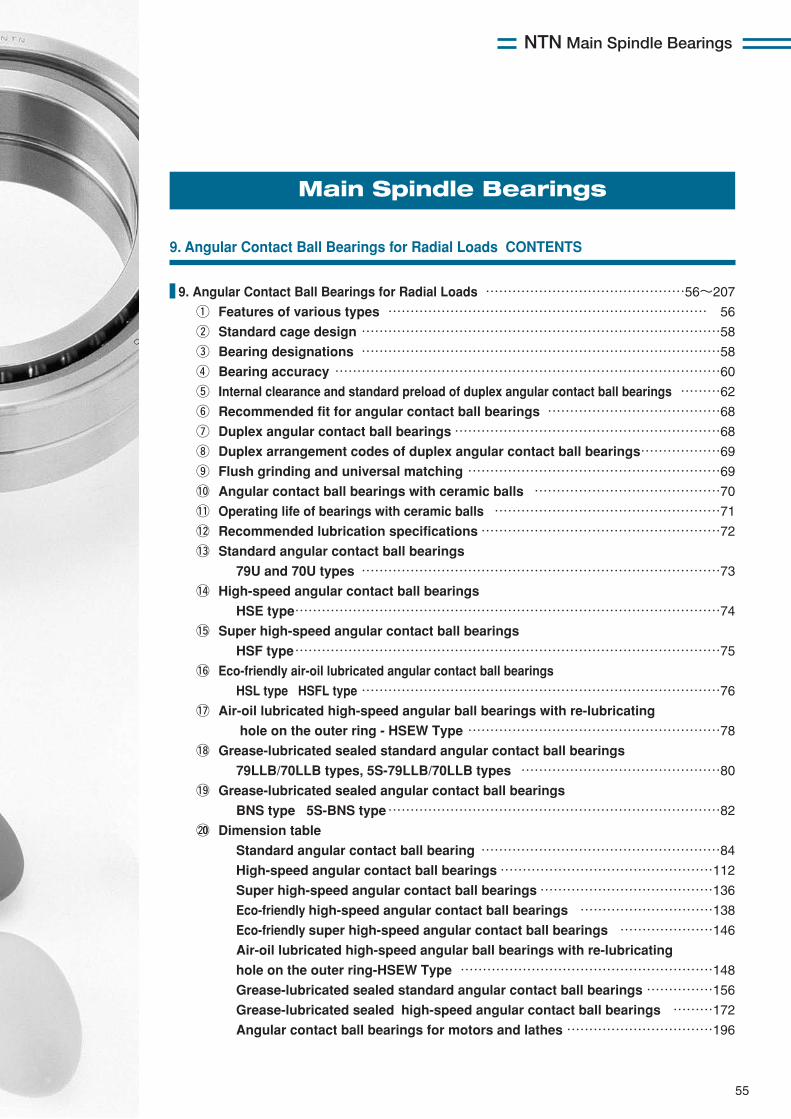
NTN Main Spindle Bearings
55
Main Spindle Bearings
9. Angular Contact Ball Bearings for Radial Loads CONTENTS
9. Angular Contact Ball Bearings for Radial Loads ………………………………………56〜207
q Features of various types ……………………………………………………………… 56
w Standard cage design ………………………………………………………………………58
e Bearing designations ………………………………………………………………………58
r Bearing accuracy ……………………………………………………………………………60
t Internal clearance and standard preload of duplex angular contact ball bearings ………62
y Recommended fit for angular contact ball bearings …………………………………68
u Duplex angular contact ball bearings……………………………………………………68
i Duplex arrangement codes of duplex angular contact ball bearings………………69
o Flush grinding and universal matching …………………………………………………69
!0 Angular contact ball bearings with ceramic balls ……………………………………70
!1 Operating life of bearings with ceramic balls ……………………………………………71
!2 Recommended lubrication specifications………………………………………………72
!3 Standard angular contact ball bearings
79U and 70U types ………………………………………………………………………73
!4 High-speed angular contact ball bearings
HSE type……………………………………………………………………………………74
!5 Super high-speed angular contact ball bearings
HSF type……………………………………………………………………………………75
!6 Eco-friendly air-oil lubricated angular contact ball bearings
HSL type HSFL type ………………………………………………………………………76
!7 Air-oil lubricated high-speed angular ball bearings with re-lubricating
hole on the outer ring - HSEW Type …………………………………………………78
!8 Grease-lubricated sealed standard angular contact ball bearings
79LLB/70LLB types, 5S-79LLB/70LLB types ………………………………………80
!9 Grease-lubricated sealed angular contact ball bearings
BNS type 5S-BNS type…………………………………………………………………82
@00 Dimension table
Standard angular contact ball bearing ………………………………………………84
High-speed angular contact ball bearings…………………………………………112
Super high-speed angular contact ball bearings…………………………………136
Eco-friendly high-speed angular contact ball bearings …………………………138
Eco-friendly super high-speed angular contact ball bearings …………………146
Air-oil lubricated high-speed angular ball bearings with re-lubricating
hole on the outer ring-HSEW Type …………………………………………………148
Grease-lubricated sealed standard angular contact ball bearings……………156
Grease-lubricated sealed high-speed angular contact ball bearings ………172
Angular contact ball bearings for motors and lathes……………………………196
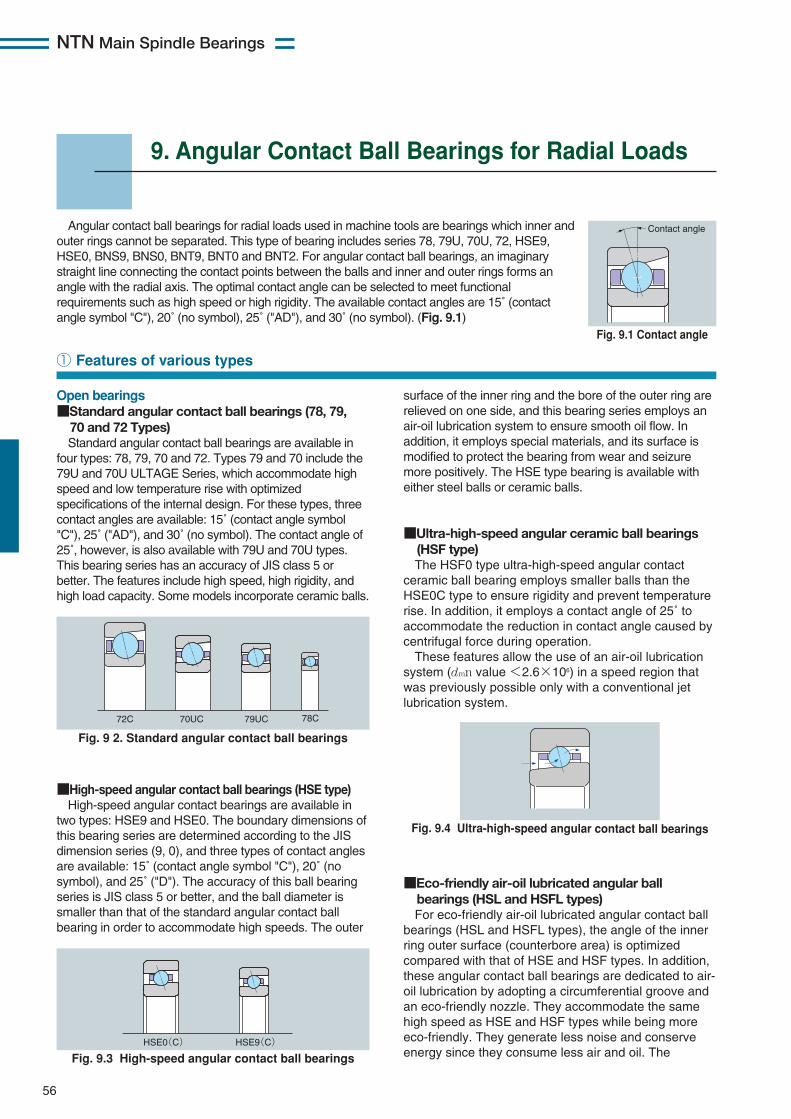
NTN Main Spindle Bearings
56
9. Angular Contact Ball Bearings for Radial Loads
Angular contact ball bearings for radial loads used in machine tools are bearings which inner andouter rings cannot be separated. This type of bearing includes series 78, 79U, 70U, 72, HSE9,HSE0, BNS9, BNS0, BNT9, BNT0 and BNT2. For angular contact ball bearings, an imaginarystraight line connecting the contact points between the balls and inner and outer rings forms anangle with the radial axis. The optimal contact angle can be selected to meet functionalrequirements such as high speed or high rigidity. The available contact angles are 15˚ (contactangle symbol "C"), 20˚ (no symbol), 25˚ ("AD"), and 30˚ (no symbol). (Fig. 9.1)
■High-speed angular contact ball bearings (HSE type)High-speed angular contact bearings are available in
two types: HSE9 and HSE0. The boundary dimensions ofthis bearing series are determined according to the JISdimension series (9, 0), and three types of contact anglesare available: 15˚ (contact angle symbol "C"), 20˚ (nosymbol), and 25˚ ("D"). The accuracy of this ball bearingseries is JIS class 5 or better, and the ball diameter issmaller than that of the standard angular contact ballbearing in order to accommodate high speeds. The outer
① Features of various types
Contact angle
Fig. 9.1 Contact angle
Fig. 9.4 Ultra-high-speed angular contact ball bearings
72C 70UC 79UC 78C
Fig. 9 2. Standard angular contact ball bearings
HSE0(C) HSE9(C)
Fig. 9.3 High-speed angular contact ball bearings
Open bearings■Standard angular contact ball bearings (78, 79, 70 and 72 Types)Standard angular contact ball bearings are available in
four types: 78, 79, 70 and 72. Types 79 and 70 include the79U and 70U ULTAGE Series, which accommodate highspeed and low temperature rise with optimizedspecifications of the internal design. For these types, threecontact angles are available: 15˚ (contact angle symbol"C"), 25˚ ("AD"), and 30˚ (no symbol). The contact angle of25˚, however, is also available with 79U and 70U types.This bearing series has an accuracy of JIS class 5 orbetter. The features include high speed, high rigidity, andhigh load capacity. Some models incorporate ceramic balls.
surface of the inner ring and the bore of the outer ring arerelieved on one side, and this bearing series employs anair-oil lubrication system to ensure smooth oil flow. Inaddition, it employs special materials, and its surface ismodified to protect the bearing from wear and seizuremore positively. The HSE type bearing is available witheither steel balls or ceramic balls.
■Ultra-high-speed angular ceramic ball bearings(HSF type)The HSF0 type ultra-high-speed angular contact
ceramic ball bearing employs smaller balls than theHSE0C type to ensure rigidity and prevent temperaturerise. In addition, it employs a contact angle of 25˚ toaccommodate the reduction in contact angle caused bycentrifugal force during operation.These features allow the use of an air-oil lubrication
system (dmn value <2.6×10⁶) in a speed region thatwas previously possible only with a conventional jetlubrication system.
■Eco-friendly air-oil lubricated angular ball bearings (HSL and HSFL types)For eco-friendly air-oil lubricated angular contact ball
bearings (HSL and HSFL types), the angle of the innerring outer surface (counterbore area) is optimizedcompared with that of HSE and HSF types. In addition,these angular contact ball bearings are dedicated to air-oil lubrication by adopting a circumferential groove andan eco-friendly nozzle. They accommodate the samehigh speed as HSE and HSF types while being moreeco-friendly. They generate less noise and conserveenergy since they consume less air and oil. The
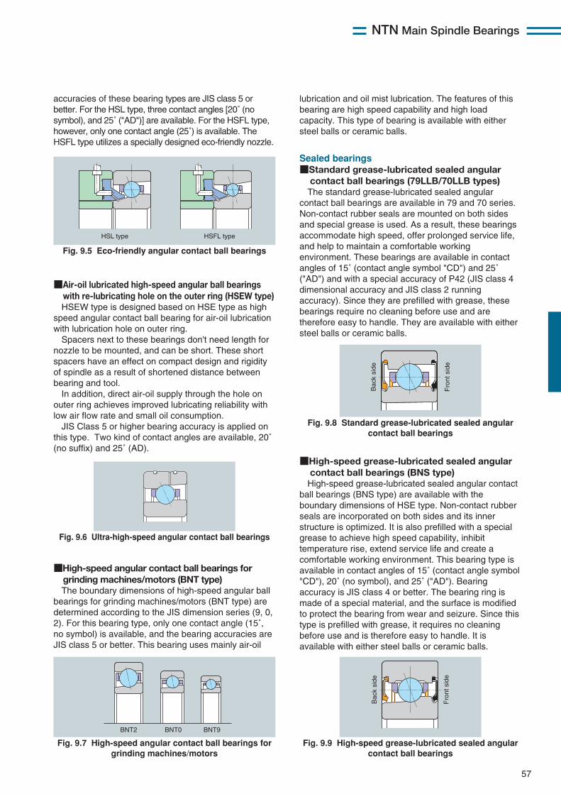
NTN Main Spindle Bearings
57
Bac
k si
de
Fro
nt s
ide
Fig. 9.8 Standard grease-lubricated sealed angularcontact ball bearings
BNT2 BNT0 BNT9
Fig. 9.7 High-speed angular contact ball bearings forgrinding machines/motors
HSL type HSFL type
Fig. 9.5 Eco-friendly angular contact ball bearings
Sealed bearings■Standard grease-lubricated sealed angular contact ball bearings (79LLB/70LLB types)The standard grease-lubricated sealed angular
contact ball bearings are available in 79 and 70 series.Non-contact rubber seals are mounted on both sidesand special grease is used. As a result, these bearingsaccommodate high speed, offer prolonged service life,and help to maintain a comfortable workingenvironment. These bearings are available in contactangles of 15˚ (contact angle symbol "CD") and 25˚("AD") and with a special accuracy of P42 (JIS class 4dimensional accuracy and JIS class 2 runningaccuracy). Since they are prefilled with grease, thesebearings require no cleaning before use and aretherefore easy to handle. They are available with eithersteel balls or ceramic balls.
Bac
k si
de
Fro
nt s
ide
Fig. 9.9 High-speed grease-lubricated sealed angularcontact ball bearings
■High-speed grease-lubricated sealed angular contact ball bearings (BNS type)High-speed grease-lubricated sealed angular contact
ball bearings (BNS type) are available with theboundary dimensions of HSE type. Non-contact rubberseals are incorporated on both sides and its innerstructure is optimized. It is also prefilled with a specialgrease to achieve high speed capability, inhibittemperature rise, extend service life and create acomfortable working environment. This bearing type isavailable in contact angles of 15˚ (contact angle symbol"CD"), 20˚ (no symbol), and 25˚ ("AD"). Bearingaccuracy is JIS class 4 or better. The bearing ring ismade of a special material, and the surface is modifiedto protect the bearing from wear and seizure. Since thistype is prefilled with grease, it requires no cleaningbefore use and is therefore easy to handle. It isavailable with either steel balls or ceramic balls.
■High-speed angular contact ball bearings for grinding machines/motors (BNT type)The boundary dimensions of high-speed angular ball
bearings for grinding machines/motors (BNT type) aredetermined according to the JIS dimension series (9, 0,2). For this bearing type, only one contact angle (15˚,no symbol) is available, and the bearing accuracies areJIS class 5 or better. This bearing uses mainly air-oil
accuracies of these bearing types are JIS class 5 orbetter. For the HSL type, three contact angles [20˚ (nosymbol), and 25˚ ("AD")] are available. For the HSFL type,however, only one contact angle (25˚) is available. TheHSFL type utilizes a specially designed eco-friendly nozzle.
Fig. 9.6 Ultra-high-speed angular contact ball bearings
■Air-oil lubricated high-speed angular ball bearingswith re-lubricating hole on the outer ring (HSEW type)HSEW type is designed based on HSE type as high
speed angular contact ball bearing for air-oil lubricationwith lubrication hole on outer ring.Spacers next to these bearings don't need length for
nozzle to be mounted, and can be short. These shortspacers have an effect on compact design and rigidityof spindle as a result of shortened distance betweenbearing and tool.In addition, direct air-oil supply through the hole on
outer ring achieves improved lubricating reliability withlow air flow rate and small oil consumption.JIS Class 5 or higher bearing accuracy is applied on
this type. Two kind of contact angles are available, 20˚(no suffix) and 25˚ (AD).
lubrication and oil mist lubrication. The features of thisbearing are high speed capability and high loadcapacity. This type of bearing is available with eithersteel balls or ceramic balls.
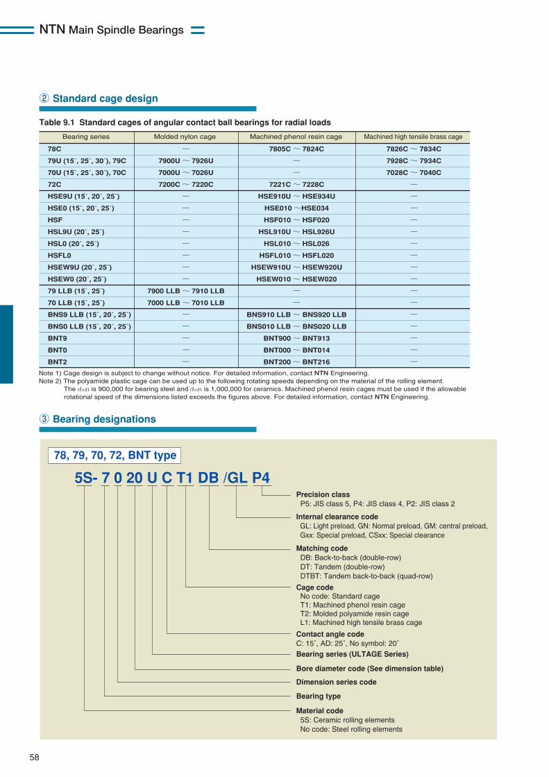
NTN Main Spindle Bearings
58
② Standard cage design
Table 9.1 Standard cages of angular contact ball bearings for radial loads
Note 1) Cage design is subject to change without notice. For detailed information, contact NTN Engineering.Note 2) The polyamide plastic cage can be used up to the following rotating speeds depending on the material of the rolling element. The dmn is 900,000 for bearing steel and dmn is 1,000,000 for ceramics. Machined phenol resin cages must be used if the allowable rotational speed of the dimensions listed exceeds the figures above. For detailed information, contact NTN Engineering.
78C
79U (15˚, 25˚, 30˚), 79C
70U (15˚, 25˚, 30˚), 70C
72C
HSE9U (15˚, 20˚, 25˚)
HSE0 (15˚, 20˚, 25˚)
HSF
HSL9U (20˚, 25˚)
HSL0 (20˚, 25˚)
HSFL0
HSEW9U (20˚, 25˚)
HSEW0 (20˚, 25˚)
79 LLB (15˚, 25˚)
70 LLB (15˚, 25˚)
BNS9 LLB (15˚, 20˚, 25˚)
BNS0 LLB (15˚, 20˚, 25˚)
BNT9
BNT0
BNT2
7900U ~ 7926U
7000U ~ 7026U
7200C ~ 7220C
7900 LLB ~ 7910 LLB
7000 LLB ~ 7010 LLB
7805C ~ 7824C
7221C ~ 7228C
HSE910U ~ HSE934U
HSE010 ~HSE034
HSF010 ~ HSF020
HSL910U ~ HSL926U
HSL010 ~ HSL026
HSFL010 ~ HSFL020
HSEW910U ~ HSEW920U
HSEW010 ~ HSEW020
BNS910 LLB ~ BNS920 LLB
BNS010 LLB ~ BNS020 LLB
BNT900 ~ BNT913
BNT000 ~ BNT014
BNT200 ~ BNT216
7826C ~ 7834C
7928C ~ 7934C
7028C ~ 7040C
Bearing series Molded nylon cage Machined phenol resin cage Machined high tensile brass cage
③ Bearing designations
5S- 7 0 20 U C T1 DB /GL P4
78, 79, 70, 72, BNT type
Precision class P5: JIS class 5, P4: JIS class 4, P2: JIS class 2
Internal clearance code GL: Light preload, GN: Normal preload, GM: central preload, Gxx: Special preload, CSxx: Special clearance
Matching code DB: Back-to-back (double-row) DT: Tandem (double-row) DTBT: Tandem back-to-back (quad-row) Cage code No code: Standard cage T1: Machined phenol resin cage T2: Molded polyamide resin cage L1: Machined high tensile brass cage Contact angle code C: 15˚, AD: 25˚, No symbol: 20˚
Bearing series (ULTAGE Series)
Bore diameter code (See dimension table)
Dimension series code
Bearing type
Material code 5S: Ceramic rolling elements No code: Steel rolling elements
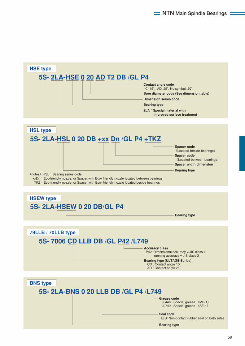
NTN Main Spindle Bearings
59
5S- 2LA-HSE 0 20 AD T2 DB /GL P4HSE type
5S- 2LA-HSL 0 20 DB +xx Dn /GL P4 +TKZHSL type
Spacer code(Located beside bearings)Spacer code(Located between bearings)Spacer width dimension
Bearing type(notes)HSL:Bearing series code xxDn:Eco-friendly nozzle, or Spacer with Eco- friendly nozzle located between bearings TKZ:Eco-friendly nozzle, or Spacer with Eco- friendly nozzle located beside bearings
5S- 2LA-HSEW 0 20 DB/GL P4HSEW type
Bearing type
5S- 7006 CD LLB DB /GL P42 /L74979LLB / 70LLB type
Accuracy class P42: Dimensional accuracy = JIS class 4, running accuracy = JIS class 2
Bearing type (ULTAGE Series) CD : Contact angle 15゜ AD : Contact angle 25゜
5S- 2LA-BNS 0 20 LLB DB /GL P4 /L749 BNS type
Grease code /L448 : Special grease (MP-1) /L749 : Special grease (SE-1)
Seal code LLB: Non-contact rubber seal on both sides
Bearing type
Contact angle code C: 15˚, AD: 25˚, No symbol: 20˚
Bore diameter code (See dimension table)
Dimension series code
Bearing type
2LA:Special material with improved surface treatment
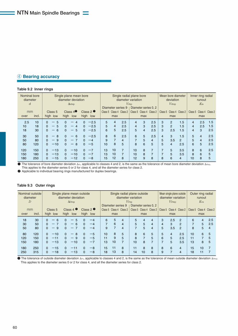
NTN Main Spindle Bearings
60
④ Bearing accuracy
Table 9.2 Inner rings
Nominal bore diameter
d mm
Single plane mean bore diameter deviation
∆dmp
Class 5 Class 41 Class 2 1
Single radial plane bore diameter variation
Vdsp
Diameter series 9
2.5 10 18
30 50 80
120 150 180
10 18 30
50 80
120
150 180 250
0 0 0
0 0 0
0 0 0
- 5 - 5 - 6
- 8 - 9 -10
-13 -13 -15
0 0 0
0 0 0
0 0 0
- 4 - 4 - 5
- 6 - 7 - 8
-10 -10 -12
0 0 0
0 0 0
0 0 0
5 5 6
8 9
10
13 13 15
4 4 5
6 7 8
10 10 12
2.5 2.5 2.5
2.5 4 5
7 7 8
-2.5 -2.5 -2.5
-2.5 -4 -5
-7 -7 -8
over incl. high low
high low high low
4 4 5
6 7 8
10 10 12
3 3 4
5 5 6
8 8 9
2.5 2.5 2.5
2.5 4 5
7 7 8
3 3 3
4 5 5
7 7 8
2 2 2.5
3 3.5 4
5 5 6
1.5 1.5 1.5
1.5 2 2.5
3.5 3.5 4
4 4 4
5 5 6
8 8
10
2.5 2.5 3
4 4 5
6 6 8
1.5 1.5 2.5
2.5 2.5 2.5
2.5 5 5
Diameter series 0, 2
Mean bore diameter deviation
Vdmp
Inner ring radial runout
Kia
Class 5 Class 4 Class 2max
Class 5 Class 4 Class 2max
Class 5 Class 4 Class 2max
Class 5 Class 4 Class 2max
1 The tolerance of bore diameter deviation ∆ds, applicable to classes 4 and 2, is the same as the tolerance of mean bore diameter deviation ∆dmp. This applies to the diameter series 0 or 2 for class 4, and all the diameter series for class 2. 2 Applicable to individual bearing rings manufactured for duplex bearings.
Table 9.3 Outer rings
Nominal outside diameter
D mm
Single plane mean outside diameter deviation
∆Dmp
Class 5 Class 4 3 Class 2 3
Single radial plane outside diameter variation
VDsp
Diameter series 9
18 30 50
80 120 150
180 250
30 50 80
120 150 180
250 315
0 0 0
0 0 0
0 0
- 6 - 7 - 9
-10 -11 -13
-15 -18
0 0 0
0 0 0
0 0
- 5 - 6 - 7
- 8 - 9 -10
-11 -13
0 0 0
0 0 0
0 0
6 7 9
10 11 13
15 18
5 6 7
8 9
10
11 13
4 4 4
5 5 7
8 8
-4 -4 -4
-5 -5 -7
-8 -8
over incl. high low
high low high low
5 5 7
8 8
10
11 14
4 5 5
6 7 8
8 10
4 4 4
5 5 7
8 8
3 4 5
5 6 7
8 9
2.5 3 3.5
4 5 5
6 7
2 2 2
2.5 2.5 3.5
4 4
6 7 8
10 11 13
15 18
4 5 5
6 7 8
10 11
2.5 2.5 4
5 5 5
7 7
Diameter series 0, 2
Mean single plane outside diameter variation
VDmp
Outer ring radial runout
Kea
Class 5 Class 4 Class 2max
Class 5 Class 4 Class 2max
Class 5 Class 4 Class 2max
Class 5 Class 4 Class 2max
3 The tolerance of outside diameter deviation ∆Ds, applicable to classes 4 and 2, is the same as the tolerance of mean outside diameter deviation ∆Dmp. This applies to the diameter series 0 or 2 for class 4, and all the diameter series for class 2.
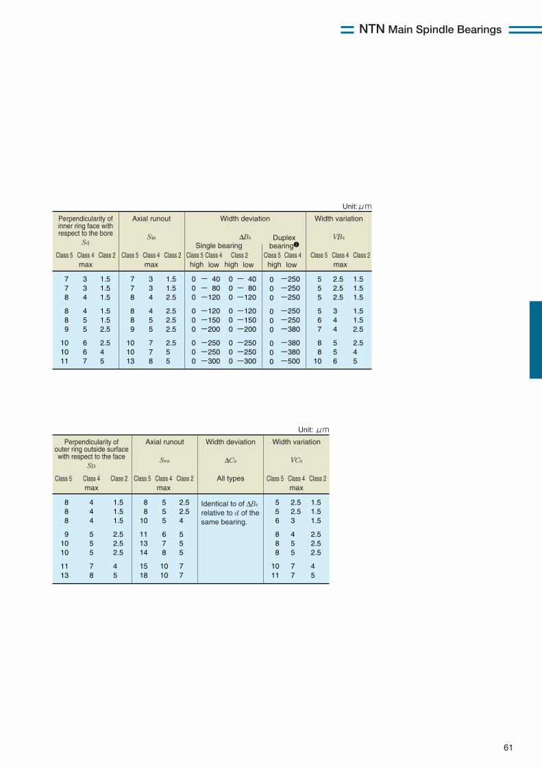
NTN Main Spindle Bearings
61
Axial runout
Sia
Width deviation
∆Bs
Width variation
VBs
7 7 8
8 8 9
10 10 13
1.5 1.5 2.5
2.5 2.5 2.5
2.5 5 5
3 3 4
4 5 5
7 7 8
5 5 5
5 6 7
8 8
10
1.5 1.5 1.5
1.5 1.5 2.5
2.5 4 5
2.5 2.5 2.5
3 4 4
5 5 6
0 0 0
0 0 0
0 0 0
- 40 - 80 -120
-120 -150 -200
-250 -250 -300
0 0 0
0 0 0
0 0 0
- 40 - 80 -120
-120 -150 -200
-250 -250 -300
0 0 0
0 0 0
0 0 0
-250 -250 -250
-250 -250 -380
-380 -380 -500
high low high low
Class 5 Class 4 Class 2max
Class 5 Class 5 Class 5Class 4 Class 4 Class 4Class 2 Class 2max
Class 5 Class 4 Class 2max
Single bearing
Duplex bearing2
high low
Perpendicularity of inner ring face with respect to the bore
Sd
7 7 8
8 8 9
10 10 11
1.5 1.5 1.5
1.5 1.5 2.5
2.5 4 5
3 3 4
4 5 5
6 6 7
Unit:μm
This applies to the diameter series 0 or 2 for class 4, and all the diameter series for class 2. 2
Axial runout
Sea
Width deviation
∆Cs
All types
Width variation
VCs
8 8
10
11 13 14
15 18
2.5 2.5 4
5 5 5
7 7
5 5 5
6 7 8
10 10
5 5 6
8 8 8
10 11
1.5 1.5 1.5
2.5 2.5 2.5
4 5
2.5 2.5 3
4 5 5
7 7
Identical to of ∆Bs relative to d of the same bearing.
Class 5 Class 4 Class 2max
Class 5 Class 4 Class 2max
Class 5 Class 4 Class 2max
Perpendicularity of outer ring outside surface with respect to the face
SD
8 8 8
9 10 10
11 13
1.5 1.5 1.5
2.5 2.5 2.5
4 5
4 4 4
5 5 5
7 8
Unit: μm
This applies to the diameter series 0 or 2 for class 4, and all the diameter series for class 2.
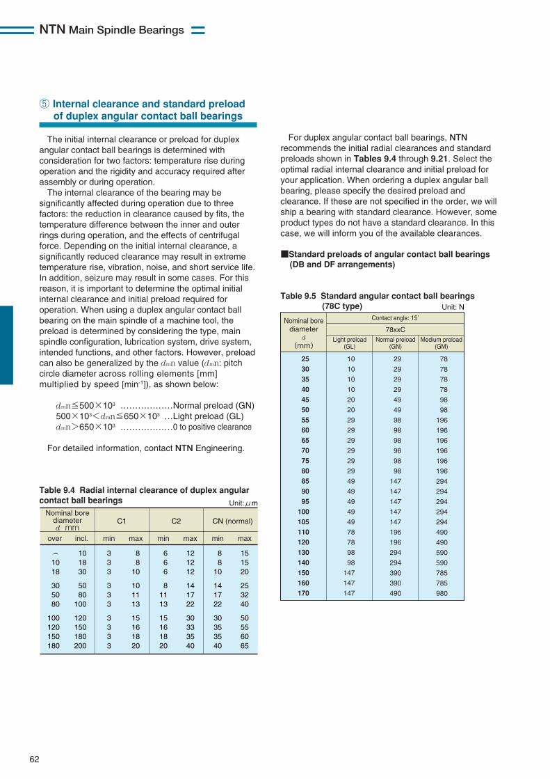
NTN Main Spindle Bearings
62
The initial internal clearance or preload for duplexangular contact ball bearings is determined withconsideration for two factors: temperature rise duringoperation and the rigidity and accuracy required afterassembly or during operation. The internal clearance of the bearing may be
significantly affected during operation due to threefactors: the reduction in clearance caused by fits, thetemperature difference between the inner and outerrings during operation, and the effects of centrifugalforce. Depending on the initial internal clearance, asignificantly reduced clearance may result in extremetemperature rise, vibration, noise, and short service life.In addition, seizure may result in some cases. For thisreason, it is important to determine the optimal initialinternal clearance and initial preload required foroperation. When using a duplex angular contact ballbearing on the main spindle of a machine tool, thepreload is determined by considering the type, mainspindle configuration, lubrication system, drive system,intended functions, and other factors. However, preloadcan also be generalized by the dmn value (dmn: pitchcircle diameter across rolling elements [mm]multiplied by speed [min-1]), as shown below:
dmn≦500×103 ………………Normal preload (GN)500×103<dmn≦650×103 …Light preload (GL)dmn>650×103 ………………0 to positive clearance
For detailed information, contact NTN Engineering.
⑤ Internal clearance and standard preload of duplex angular contact ball bearings
Nominal bore diameter d mm
C1
over incl. min max
C2
min max
CN (normal)
min max
– 10 18
30 50 80
100 120 150 180
10 18 30
50 80
100
120 150 180 200
3 3 3
3 3 3
3 3 3 3
8 8
10
10 11 13
15 16 18 20
6 6 6
8 11 13
15 16 18 20
12 12 12
14 17 22
30 33 35 40
8 8
10
14 17 22
30 35 35 40
15 15 20
25 32 40
50 55 60 65
Unit:μm
Table 9.4 Radial internal clearance of duplex angularcontact ball bearings
Table 9.5 Standard angular contact ball bearings(78C type)
25
30
35
40
45
50
55
60
65
70
75
80
85
90
95
100
105
110
120
130
140
150
160
170
10
10
10
10
20
20
29
29
29
29
29
29
49
49
49
49
49
78
78
98
98
147
147
147
29
29
29
29
49
49
98
98
98
98
98
98
147
147
147
147
147
196
196
294
294
390
390
490
78
78
78
78
98
98
196
196
196
196
196
196
294
294
294
294
294
490
490
590
590
785
785
980
Nominal bore diameter
d (mm)
Contact angle: 15˚
78xxCLight preload
(GL)Normal preload
(GN)Medium preload
(GM)
Unit: N
For duplex angular contact ball bearings, NTNrecommends the initial radial clearances and standardpreloads shown in Tables 9.4 through 9.21. Select theoptimal radial internal clearance and initial preload foryour application. When ordering a duplex angular ballbearing, please specify the desired preload andclearance. If these are not specified in the order, we willship a bearing with standard clearance. However, someproduct types do not have a standard clearance. In thiscase, we will inform you of the available clearances.
■Standard preloads of angular contact ball bearings (DB and DF arrangements)
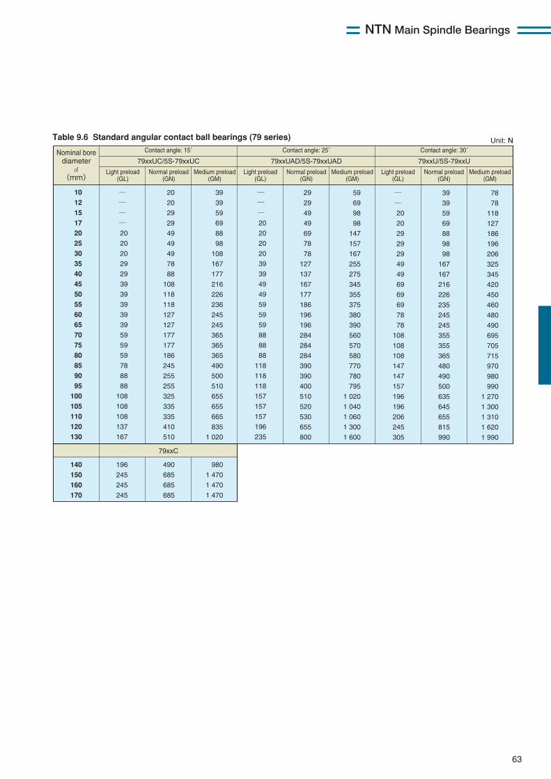
NTN Main Spindle Bearings
63
Table 9.6 Standard angular contact ball bearings (79 series)
10
12
15
17
20
25
30
35
40
45
50
55
60
65
70
75
80
85
90
95
100
105
110
120
130
―
―
―
―
20
20
20
29
29
39
39
39
39
39
59
59
59
78
88
88
108
108
108
137
167
―
―
―
20
20
20
20
39
39
49
49
59
59
59
88
88
88
118
118
118
157
157
157
196
235
20
20
29
29
49
49
49
78
88
108
118
118
127
127
177
177
186
245
255
255
325
335
335
410
510
39
39
59
69
88
98
108
167
177
216
226
236
245
245
365
365
365
490
500
510
655
655
665
835
1 020
140
150
160
170
196
245
245
245
490
685
685
685
980
1 470
1 470
1 470
29
29
49
49
69
78
78
127
137
167
177
186
196
196
284
284
284
390
390
400
510
520
530
655
800
59
69
98
98
147
157
167
255
275
345
355
375
380
390
560
570
580
770
780
795
1 020
1 040
1 060
1 300
1 600
―
―
20
20
29
29
29
49
49
69
69
69
78
78
108
108
108
147
147
157
196
196
206
245
305
39
39
59
69
88
98
98
167
167
216
226
235
245
245
355
355
365
480
490
500
635
645
655
815
990
78
78
118
127
186
196
206
325
345
420
450
460
480
490
695
705
715
970
980
990
1 270
1 300
1 310
1 620
1 990
Contact angle: 15˚
79xxUC/5S-79xxUC
79xxC
Contact angle: 25˚
79xxUAD/5S-79xxUAD
Contact angle: 30˚
79xxU/5S-79xxUNominal bore
diameter d
(mm) Light preload
(GL)Normal preload
(GN)Medium preload
(GM)Light preload
(GL)Normal preload
(GN)Medium preload
(GM)Light preload
(GL)Normal preload
(GN)Medium preload
(GM)
Unit: N

NTN Main Spindle Bearings
64
Table 9.8 Standard angular contact ball bearings (72C series)
Table 9.7 Standard angular contact ball bearings (70 series)
10
12
15
17
20
25
30
35
40
45
50
55
60
65
70
75
80
85
90
95
100
105
110
120
130
140
150
160
170
180
190
200
―
―
―
20
20
29
29
39
39
49
49
69
69
78
98
98
118
127
147
157
157
186
206
216
265
294
294
490
490
490
590
590
20
20
20
20
29
39
49
59
59
69
78
98
108
108
137
137
177
177
206
216
226
255
294
305
380
29
39
39
49
69
78
98
118
127
147
157
216
216
226
294
294
365
375
440
460
460
550
630
635
800
785
785
980
980
980
1 470
1 470
59
69
78
98
137
147
186
235
255
300
325
420
430
460
580
600
725
750
890
910
930
1 090
1 250
1 270
1 600
1 960
1 960
2 450
2 450
2 450
3 450
3 450
49
59
59
78
108
118
147
186
206
245
255
335
345
365
460
470
580
590
705
715
740
860
990
1 010
1 270
108
108
127
157
216
235
305
380
400
480
510
665
680
725
920
940
1 150
1 180
1 400
1 430
1 470
1 720
1 980
2 020
2 530
20
20
29
29
39
49
59
69
78
88
98
127
127
137
177
177
216
226
265
275
284
335
380
380
480
69
69
78
98
137
147
186
235
255
305
325
420
430
450
580
590
715
735
875
900
920
1 070
1 230
1 260
1 570
127
137
157
196
265
294
375
480
510
600
635
845
855
900
1 150
1 180
1 430
1 470
1 750
1 790
1 830
2 140
2 460
2 510
3 150
Contact angle: 15˚
70xxUC/5S-70xxUC
70xxC
Contact angle: 25˚
70xxUAD/5S-70xxUAD
Contact angle: 30˚
70xxU/5S-70xxUNominal bore
diameter d
(mm) Light preload
(GL)Normal preload
(GN)Medium preload
(GM)Light preload
(GL)Normal preload
(GN)Medium preload
(GM)Light preload
(GL)Normal preload
(GN)Medium preload
(GM)
Unit: N
10
12
15
17
20
25
30
35
40
45
50
55
60
65
70
75
80
85
90
95
100
105
110
120
130
20
20
20
20
49
49
49
78
78
98
98
147
147
147
196
196
196
294
294
294
294
390
390
390
490
49
49
49
49
98
98
98
196
196
294
294
390
390
390
490
490
490
685
685
685
685
980
980
980
1 470
98
98
147
147
294
294
294
490
490
590
590
785
785
785
980
980
980
1 470
1 470
1 960
1 960
2 450
2 450
2 450
2 940
72xxC
Contact angle: 15˚ Nominal bore diameter
d (mm)
Light preload (GL)
Normal preload (GN)
Medium preload (GM)
Unit: N
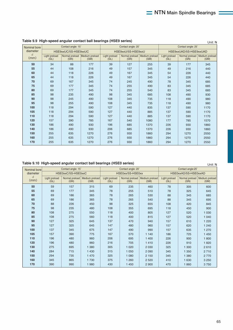
NTN Main Spindle Bearings
65
Table 9.9 High-speed angular contact ball bearings (HSE9 series)
Table 9.10 High-speed angular contact ball bearings (HSE0 series)
50
55
60
65
70
75
80
85
90
95
100
105
110
120
130
140
150
160
170
34
44
44
44
69
69
69
98
98
98
118
118
118
157
186
186
255
255
255
39
49
49
49
74
74
74
98
108
108
127
127
127
167
196
206
276
276
276
88
108
118
118
167
177
177
235
245
255
294
294
294
390
490
490
635
635
635
177
216
226
226
345
345
345
490
490
490
590
590
590
785
930
930
1270
1270
1270
127
157
167
167
245
255
255
345
345
345
440
440
440
540
685
685
930
930
930
255
345
345
345
490
490
540
685
735
735
835
885
885
1080
1370
1370
1860
1860
1860
39
49
54
54
78
83
83
108
118
118
137
137
137
177
226
226
294
294
294
177
216
226
226
345
345
345
490
490
490
590
590
590
785
930
930
1270
1270
1270
345
440
440
440
685
685
685
930
980
980
1170
1170
1170
1570
1860
1860
2550
2550
2550
Contact angle: 15˚
HSE9xxUC/5S-HSE9xxUC HSE9xxU/5S-HSE9xxU HSE9xxUAD/5S-HSE9xxUAD
Contact angle: 20˚ Contact angle: 25˚ Nominal bore diameter
d (mm)
Light preload (GL)
Normal preload (GN)
Medium preload (GM)
Light preload (GL)
Normal preload (GN)
Medium preload (GM)
Light preload (GL)
Normal preload (GN)
Medium preload (GM)
Unit: N
50
55
60
65
70
75
80
85
90
95
100
105
110
120
130
140
150
160
170
59
69
69
69
88
98
108
108
127
127
137
157
196
196
275
284
294
345
390
69
78
78
78
98
108
118
118
137
147
147
167
206
216
305
315
325
375
430
157
177
186
186
226
235
275
275
325
325
345
390
480
480
695
715
735
865
990
315
345
365
365
450
480
550
560
645
645
675
775
960
960
1 380
1 430
1 470
1 730
1 980
235
255
265
265
325
355
400
400
470
480
490
570
695
705
1 020
1 050
1 080
1 260
1 450
460
510
530
540
655
695
805
815
940
960
990
1 140
1 400
1 410
2 030
2 090
2 150
2 520
2 900
78
78
88
88
108
118
127
127
157
157
157
186
226
226
325
345
345
410
470
305
325
345
345
420
450
520
520
610
620
635
725
900
910
1 300
1 350
1 380
1 630
1 860
600
645
685
695
845
900
1 030
1 040
1 220
1 240
1 270
1 450
1 800
1 820
2 610
2 710
2 770
3 250
3 750
Contact angle: 15˚
HSE0xxC/5S-HSE0xxC HSE0xx/5S-HSE0xx HSE0xxAD/5S-HSE0xxAD
Contact angle: 20˚ Contact angle:25˚ Nominal bore diameter
d (mm)
Light preload (GL)
Normal preload (GN)
Medium preload (GM)
Light preload (GL)
Normal preload (GN)
Medium preload (GM)
Light preload (GL)
Normal preload (GN)
Medium preload (GM)
Unit: N
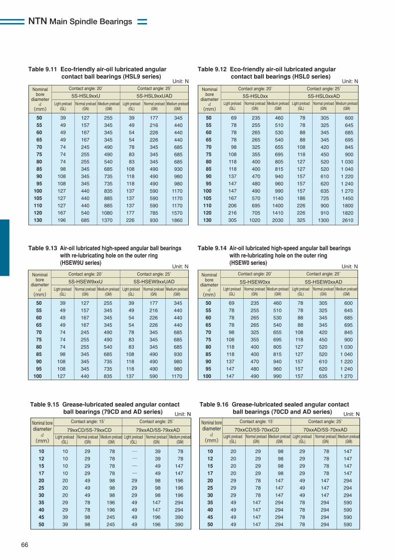
NTN Main Spindle Bearings
66
Table 9.15 Grease-lubricated sealed angular contact ball bearings (79CD and AD series)
50
55
60
65
70
75
80
85
90
95
100
105
110
120
130
39
49
49
49
74
74
74
98
108
108
127
127
127
167
196
39
49
54
54
78
83
83
108
118
118
137
137
137
177
226
127
157
167
167
245
255
255
345
345
345
440
440
440
540
685
255
345
345
345
490
490
540
685
735
735
835
885
885
1080
1370
177
216
226
226
345
345
345
490
490
490
590
590
590
785
930
345
440
440
440
685
685
685
930
980
980
1170
1170
1170
1570
1860
Nominalbore
diameterd
(mm)
Contact angle: 20˚
5S-HSL9xxU 5S-HSL9xxUAD
Contact angle: 25˚
Unit: N
Light preload(GL)
Light preload(GL)
Normal preload(GN)
Normal preload(GN)
Medium preload(GM)
Medium preload(GM)
50
55
60
65
70
75
80
85
90
95
100
105
110
120
130
69
78
78
78
98
108
118
118
137
147
147
167
206
216
305
78
78
88
88
108
118
127
127
157
157
157
186
226
226
325
235
255
265
265
325
355
400
400
470
480
490
570
695
705
1020
460
510
530
540
655
695
805
815
940
960
990
1140
1400
1410
2030
305
325
345
345
420
450
520
520
610
620
635
725
900
910
1300
600
645
685
695
845
900
1 030
1 040
1 220
1 240
1 270
1450
1800
1820
2610
Nominalbore
diameterd
(mm)
Contact angle: 20˚
5S-HSL0xx 5S-HSL0xxAD
Contact angle: 25˚
Unit: N
Light preload(GL)
Normal preload(GN)
Medium preload(GM)
Light preload(GL)
Normal preload(GN)
Medium preload(GM)
10
12
15
17
20
25
30
35
40
45
50
10
10
10
10
20
20
20
29
29
39
39
―
―
―
―
29
29
29
49
49
49
49
29
29
29
29
49
49
49
78
78
98
98
78
78
78
78
98
98
98
196
196
245
245
39
39
49
49
98
98
98
147
147
196
196
78
78
147
147
196
196
196
294
294
390
390
Contact angle: 15˚
79xxCD/5S-79xxCD 79xxAD/5S-79xxAD
Contact angle: 25˚ Nominal bore diameter
d (mm)
Light preload (GL)
Normal preload (GN)
Medium preload (GM)
Light preload (GL)
Normal preload (GN)
Medium preload (GM)
Unit: N
Table 9.16 Grease-lubricated sealed angular contact ball bearings (70CD and AD series)
10
12
15
17
20
25
30
35
40
45
50
20
20
20
20
29
29
29
49
49
49
49
29
29
29
29
49
49
49
78
78
78
78
29
29
29
29
78
78
78
147
147
147
147
98
98
98
98
147
147
147
294
294
294
294
78
78
78
78
147
147
147
294
294
294
294
147
147
147
147
294
294
294
590
590
590
590
Contact angle: 15˚
70xxCD/5S-70xxCD 70xxAD/5S-70xxAD
Contact angle: 25˚ Nominal bore diameter
d (mm)
Light preload (GL)
Normal preload (GN)
Medium preload (GM)
Light preload (GL)
Normal preload (GN)
Medium preload (GM)
Unit: N
Table 9.11 Eco-friendly air-oil lubricated angularcontact ball bearings (HSL9 series)
Table 9.12 Eco-friendly air-oil lubricated angularcontact ball bearings (HSL0 series)
Table 9.13 Air-oil lubricated high-speed angular ball bearingswith re-lubricating hole on the outer ring(HSEW9U series)
Table 9.14 Air-oil lubricated high-speed angular ball bearingswith re-lubricating hole on the outer ring(HSEW0 series)
50
55
60
65
70
75
80
85
90
95
100
39
49
49
49
74
74
74
98
108
108
127
39
49
54
54
78
83
83
108
118
118
137
127
157
167
167
245
255
255
345
345
345
440
255
345
345
345
490
490
540
685
735
735
835
177
216
226
226
345
345
345
490
490
490
590
345
440
440
440
685
685
685
930
980
980
1170
Nominalbore
diameterd
(mm)
Contact angle: 20˚
5S-HSEW9xxU 5S-HSEW9xxUAD
Contact angle: 25˚
Unit: N
Light preload(GL)
Normal preload(GN)
Medium preload(GM)
Light preload(GL)
Normal preload(GN)
Medium preload(GM)
50
55
60
65
70
75
80
85
90
95
100
69
78
78
78
98
108
118
118
137
147
147
78
78
88
88
108
118
127
127
157
157
157
235
255
265
265
325
355
400
400
470
480
490
460
510
530
540
655
695
805
815
940
960
990
305
325
345
345
420
450
520
520
610
620
635
600
645
685
695
845
900
1 030
1 040
1 220
1 240
1 270
Nominalbore
diameterd
(mm)
Contact angle: 20˚
5S-HSEW0xx 5S-HSEW0xxAD
Contact angle: 25˚
Unit: N
Light preload(GL)
Normal preload(GN)
Medium preload(GM)
Light preload(GL)
Normal preload(GN)
Medium preload(GM)
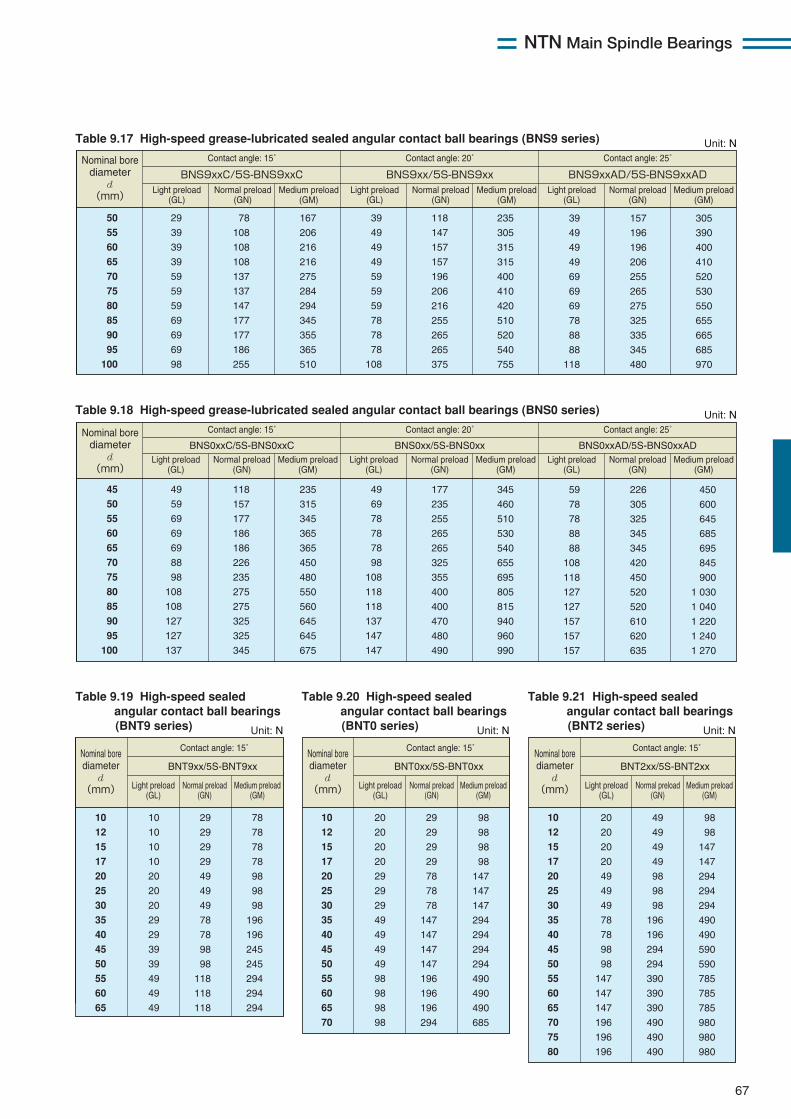
NTN Main Spindle Bearings
67
Table 9.21 High-speed sealed angular contact ball bearings(BNT2 series)
Table 9.17 High-speed grease-lubricated sealed angular contact ball bearings (BNS9 series)
Table 9.19 High-speed sealed angular contact ball bearings(BNT9 series)
Table 9.20 High-speed sealed angular contact ball bearings(BNT0 series)
50
55
60
65
70
75
80
85
90
95
100
29
39
39
39
59
59
59
69
69
69
98
39
49
49
49
59
59
59
78
78
78
108
78
108
108
108
137
137
147
177
177
186
255
167
206
216
216
275
284
294
345
355
365
510
118
147
157
157
196
206
216
255
265
265
375
235
305
315
315
400
410
420
510
520
540
755
39
49
49
49
69
69
69
78
88
88
118
157
196
196
206
255
265
275
325
335
345
480
305
390
400
410
520
530
550
655
665
685
970
Contact angle: 15˚
BNS9xxC/5S-BNS9xxC BNS9xx/5S-BNS9xx BNS9xxAD/5S-BNS9xxAD
Contact angle: 20˚ Contact angle: 25˚ Nominal bore diameter
d (mm)
Light preload (GL)
Normal preload (GN)
Medium preload (GM)
Light preload (GL)
Normal preload (GN)
Medium preload (GM)
Light preload (GL)
Normal preload (GN)
Medium preload (GM)
Unit: N
Table 9.18 High-speed grease-lubricated sealed angular contact ball bearings (BNS0 series)
45
50
55
60
65
70
75
80
85
90
95
100
49
59
69
69
69
88
98
108
108
127
127
137
49
69
78
78
78
98
108
118
118
137
147
147
118
157
177
186
186
226
235
275
275
325
325
345
235
315
345
365
365
450
480
550
560
645
645
675
177
235
255
265
265
325
355
400
400
470
480
490
345
460
510
530
540
655
695
805
815
940
960
990
59
78
78
88
88
108
118
127
127
157
157
157
226
305
325
345
345
420
450
520
520
610
620
635
450
600
645
685
695
845
900
1 030
1 040
1 220
1 240
1 270
Contact angle: 15˚
BNS0xxC/5S-BNS0xxC BNS0xx/5S-BNS0xx BNS0xxAD/5S-BNS0xxAD
Contact angle: 20˚ Contact angle: 25˚ Nominal bore diameter
d (mm)
Light preload (GL)
Normal preload (GN)
Medium preload (GM)
Light preload (GL)
Normal preload (GN)
Medium preload (GM)
Light preload (GL)
Normal preload (GN)
Medium preload (GM)
Unit: N
10
12
15
17
20
25
30
35
40
45
50
55
60
65
10
10
10
10
20
20
20
29
29
39
39
49
49
49
29
29
29
29
49
49
49
78
78
98
98
118
118
118
78
78
78
78
98
98
98
196
196
245
245
294
294
294
Contact angle: 15˚
BNT9xx/5S-BNT9xx
10
12
15
17
20
25
30
35
40
45
50
55
60
65
70
20
20
20
20
29
29
29
49
49
49
49
98
98
98
98
29
29
29
29
78
78
78
147
147
147
147
196
196
196
294
98
98
98
98
147
147
147
294
294
294
294
490
490
490
685
Contact angle: 15˚
BNT0xx/5S-BNT0xx
10
12
15
17
20
25
30
35
40
45
50
55
60
65
70
75
80
20
20
20
20
49
49
49
78
78
98
98
147
147
147
196
196
196
49
49
49
49
98
98
98
196
196
294
294
390
390
390
490
490
490
98
98
147
147
294
294
294
490
490
590
590
785
785
785
980
980
980
Contact angle: 15˚
BNT2xx/5S-BNT2xxNominal bore diameter
d (mm)
Nominal bore diameter
d (mm)
Nominal bore diameter
d (mm) Light preload
(GL)Normal preload
(GN)Medium preload
(GM)Light preload
(GL)Normal preload
(GN)Medium preload
(GM)Light preload
(GL)Normal preload
(GN)Medium preload
(GM)
Unit: N Unit: N Unit: N
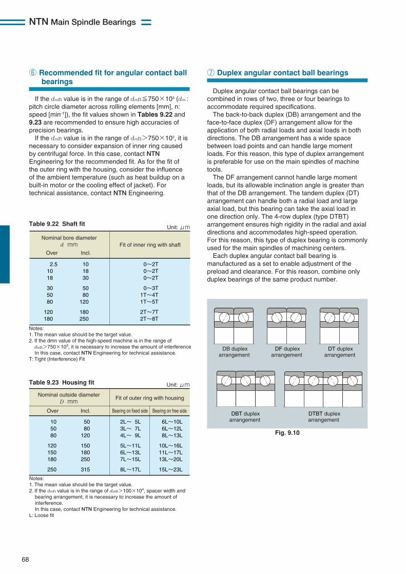
NTN Main Spindle Bearings
68
If the dmn value is in the range of dmn≦750×103 (dm :pitch circle diameter across rolling elements [mm], n:speed [min-1]), the fit values shown in Tables 9.22 and9.23 are recommended to ensure high accuracies ofprecision bearings.If the dmn value is in the range of dmn>750×103, it is
necessary to consider expansion of inner ring causedby centrifugal force. In this case, contact NTNEngineering for the recommended fit. As for the fit ofthe outer ring with the housing, consider the influenceof the ambient temperature (such as heat buildup on abuilt-in motor or the cooling effect of jacket). Fortechnical assistance, contact NTN Engineering.
⑥ Recommended fit for angular contact ballbearings
Table 9.22 Shaft fit
Table 9.23 Housing fit
Nominal bore diameter d mm Fit of inner ring with shaft
Over Incl.
2.5 10 18
30 50 80
120 180
10 18 30
50 80
120
180 250
0~2T 0~2T 0~2T
0~3T 1T~4T 1T~5T
2T~7T 2T~8T
Unit: μm
Notes: 1. The mean value should be the target value. 2. If the dmn value of the high-speed machine is in the range of dmn>750×103, it is necessary to increase the amount of interference. In this case, contact NTN Engineering for technical assistance. T: Tight (Interference) Fit
Nominal outside diameter D mm
Fit of outer ring with housing
Over Incl. Bearing on fixed side Bearing on free side
10 50 80
120 150 180
250
50 80
120
150 180 250
315
2L~ 5L 3L~ 7L 4L~ 9L
5L~11L 6L~13L 7L~15L
8L~17L
6L~10L 6L~12L 8L~13L
10L~16L 11L~17L 13L~20L
15L~23L
Unit: μm
Notes: 1. The mean value should be the target value. 2. If the dmn value is in the range of dmn>100×104, spacer width and bearing arrangement, it is necessary to increase the amount of interference. In this case, contact NTN Engineering for technical assistance. L: Loose fit
Duplex angular contact ball bearings can becombined in rows of two, three or four bearings toaccommodate required specifications.The back-to-back duplex (DB) arrangement and the
face-to-face duplex (DF) arrangement allow for theapplication of both radial loads and axial loads in bothdirections. The DB arrangement has a wide spacebetween load points and can handle large momentloads. For this reason, this type of duplex arrangementis preferable for use on the main spindles of machinetools.The DF arrangement cannot handle large moment
loads, but its allowable inclination angle is greater thanthat of the DB arrangement. The tandem duplex (DT)arrangement can handle both a radial load and largeaxial load, but this bearing can take the axial load inone direction only. The 4-row duplex (type DTBT)arrangement ensures high rigidity in the radial and axialdirections and accommodates high-speed operation.For this reason, this type of duplex bearing is commonlyused for the main spindles of machining centers.Each duplex angular contact ball bearing is
manufactured as a set to enable adjustment of thepreload and clearance. For this reason, combine onlyduplex bearings of the same product number.
⑦ Duplex angular contact ball bearings
DB duplex arrangement
DF duplex arrangement
DT duplex arrangement
DBT duplex arrangement
DTBT duplex arrangement
Fig. 9.10
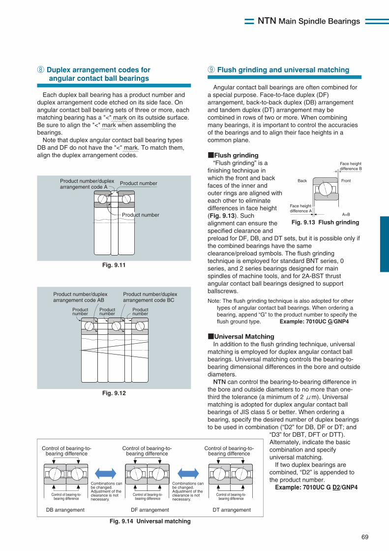
NTN Main Spindle Bearings
69
Each duplex ball bearing has a product number andduplex arrangement code etched on its side face. Onangular contact ball bearing sets of three or more, eachmatching bearing has a "<" mark on its outside surface.Be sure to align the "<" mark when assembling thebearings.Note that duplex angular contact ball bearing types
DB and DF do not have the "<" mark. To match them,align the duplex arrangement codes.
⑧ Duplex arrangement codes forangular contact ball bearings
Angular contact ball bearings are often combined fora special purpose. Face-to-face duplex (DF)arrangement, back-to-back duplex (DB) arrangementand tandem duplex (DT) arrangement may becombined in rows of two or more. When combiningmany bearings, it is important to control the accuraciesof the bearings and to align their face heights in acommon plane.
■Flush grinding“Flush grinding” is a
finishing technique inwhich the front and backfaces of the inner andouter rings are aligned witheach other to eliminatedifferences in face height(Fig. 9.13). Suchalignment can ensure thespecified clearance andpreload for DF, DB, and DT sets, but it is possible only ifthe combined bearings have the sameclearance/preload symbols. The flush grindingtechnique is employed for standard BNT series, 0series, and 2 series bearings designed for mainspindles of machine tools, and for 2A-BST thrustangular contact ball bearings designed to supportballscrews.
Note: The flush grinding technique is also adopted for othertypes of angular contact ball bearings. When ordering abearing, append “G” to the product number to specify theflush ground type. Example: 7010UC G/GNP4
■Universal MatchingIn addition to the flush grinding technique, universal
matching is employed for duplex angular contact ballbearings. Universal matching controls the bearing-to-bearing dimensional differences in the bore and outsidediameters.
NTN can control the bearing-to-bearing difference inthe bore and outside diameters to no more than one-third the tolerance (a minimum of 2 μm). Universalmatching is adopted for duplex angular contact ballbearings of JIS class 5 or better. When ordering abearing, specify the desired number of duplex bearingsto be used in combination (“D2” for DB, DF or DT; and
“D3” for DBT, DFT or DTT).Alternately, indicate the basiccombination and specifyuniversal matching.If two duplex bearings are
combined, “D2” is appended tothe product number.Example: 7010UC G D2/GNP4
⑨ Flush grinding and universal matching
Product numberProduct number/duplex arrangement code A
Product number
Product number/duplex arrangement code AB
Product number/duplex arrangement code BC
Product number
Product number
Product number
Fig. 9.11
Fig. 9.12
Fig. 9.13 Flush grinding
~~~
~~~
~~~
Back Front
Face height difference A
Face height difference B
A=B
Fig. 9.14 Universal matching
Control of bearing-to- bearing difference
Control of bearing-to- bearing difference
Control of bearing-to- bearing difference
Control of bearing-to- bearing difference
Control of bearing-to- bearing difference
Control of bearing-to- bearing difference
DB arrangement DF arrangement DT arrangement
Combinations can be changed. Adjustment of the clearance is not necessary.
Combinations can be changed. Adjustment of the clearance is not necessary.
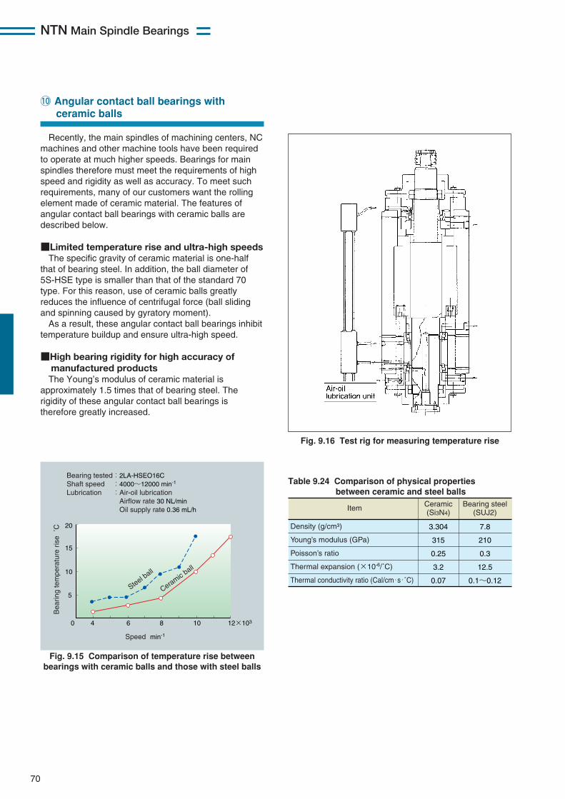
NTN Main Spindle Bearings
70
Recently, the main spindles of machining centers, NCmachines and other machine tools have been requiredto operate at much higher speeds. Bearings for mainspindles therefore must meet the requirements of highspeed and rigidity as well as accuracy. To meet suchrequirements, many of our customers want the rollingelement made of ceramic material. The features ofangular contact ball bearings with ceramic balls aredescribed below.
■Limited temperature rise and ultra-high speedsThe specific gravity of ceramic material is one-half
that of bearing steel. In addition, the ball diameter of5S-HSE type is smaller than that of the standard 70type. For this reason, use of ceramic balls greatlyreduces the influence of centrifugal force (ball slidingand spinning caused by gyratory moment).As a result, these angular contact ball bearings inhibit
temperature buildup and ensure ultra-high speed.
■High bearing rigidity for high accuracy ofmanufactured productsThe Young’s modulus of ceramic material is
approximately 1.5 times that of bearing steel. Therigidity of these angular contact ball bearings istherefore greatly increased.
!0 Angular contact ball bearings with ceramic balls
Bearing tested:2LA-HSEO16C Shaft speed :4000~12000 min-1 Lubrication :Air-oil lubrication Airflow rate 30 NL/min Oil supply rate 0.36 mL/h
Bea
ring
tem
pera
ture
ris
e ˚
C
Steel ball
Ceramic ball
Speed min-1
20
15
10
5
40 6 8 10 12×103
Fig. 9.15 Comparison of temperature rise betweenbearings with ceramic balls and those with steel balls
Fig. 9.16 Test rig for measuring temperature rise
Item Ceramic (Si3N4)
Bearing steel (SUJ2)
3.304
315
0.25
3.2
0.07
7.8
210
0.3
12.5
0.1~0.12
Density (g/cm3)
Young’s modulus (GPa)
Poisson’s ratio
Thermal expansion (×10-6/˚C)
Thermal conductivity ratio (Cal/cm・s・˚C)
Table 9.24 Comparison of physical properties between ceramic and steel balls

NTN Main Spindle Bearings
71
!1 Operating life of bearings with ceramic balls
Coupling
Pulley
Loading spring
Support bearing6312
Test bearing
Fig. 9.17 Radial load-type bearing life test machine
99
80
50
20
10
5
101 2 4 6 8102 2 4 8103 2 4 6 82 4 6 8104
Hatched area: With steel balls ▲: With ceramic balls
Acc
umul
ativ
e pr
obab
ility
of f
ailu
re %
Operating life(Ln)
Fig. 9.18 Operating life of ball bearing with ceramic balls
70
60
50
40
30
20
10
0
5,0000 10,000 15,000 20,000
Speed(min-1)
Bea
ring
fric
tion
torq
ue(
N・
mm)
Steel ball
Ceramic ball
Fig. 9.19 Frictional torque
25
20
15
10
5
00 100 200 300 400 500 600 700 800
Axial load(N)
Dis
plac
emen
t in
axia
l dire
ctio
n(μm)
Steel ball
Ceramic ball
Fig. 9.20 Displacement in axial direction
Test conditionsBearing tested:6206 Bearing load :6860 N{700 kgf}Shaft speed :2000 min-1
Lubrication :Class 1 turbine oil (VG56), circulating lubrication
Test machine
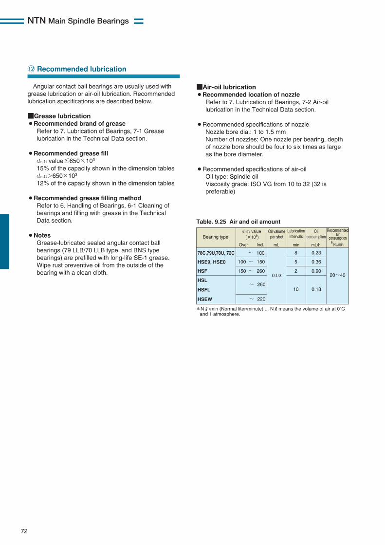
NTN Main Spindle Bearings
72
Angular contact ball bearings are usually used withgrease lubrication or air-oil lubrication. Recommendedlubrication specifications are described below.
■Grease lubrication¡Recommended brand of grease
Refer to 7. Lubrication of Bearings, 7-1 Greaselubrication in the Technical Data section.
¡Recommended grease filldmn value≦650×103
15% of the capacity shown in the dimension tablesdmn>650×103
12% of the capacity shown in the dimension tables
¡Recommended grease filling methodRefer to 6. Handling of Bearings, 6-1 Cleaning ofbearings and filling with grease in the TechnicalData section.
¡NotesGrease-lubricated sealed angular contact ballbearings (79 LLB/70 LLB type, and BNS typebearings) are prefilled with long-life SE-1 grease.Wipe rust preventive oil from the outside of thebearing with a clean cloth.
!2 Recommended lubrication
Table. 9.25 Air and oil amount
78C,79U,70U, 72C
HSE9, HSE0
HSF
HSL
HSEW
HSFL
~ 100
100 ~ 150
0.03
8
5
2
10
150 ~ 26020~40
~ 260
~ 220
0.23
0.36
0.90
0.18
*NR/min (Normal liter/minute) ... NRmeans the volume of air at 0˚C and 1 atmosphere.
*NL/min
Bearing typedmn value
(×106)
Over Incl.
Oil valumeper shot
minmL mL/h
Oilconsumption
Recommendedair
consumption
Lubricationintervals
■Air-oil lubrication¡Recommended location of nozzle
Refer to 7. Lubrication of Bearings, 7-2 Air-oillubrication in the Technical Data section.
¡Recommended specifications of nozzleNozzle bore dia.: 1 to 1.5 mmNumber of nozzles: One nozzle per bearing, depthof nozzle bore should be four to six times as largeas the bore diameter.
¡Recommended specifications of air-oilOil type: Spindle oilViscosity grade: ISO VG from 10 to 32 (32 ispreferable)
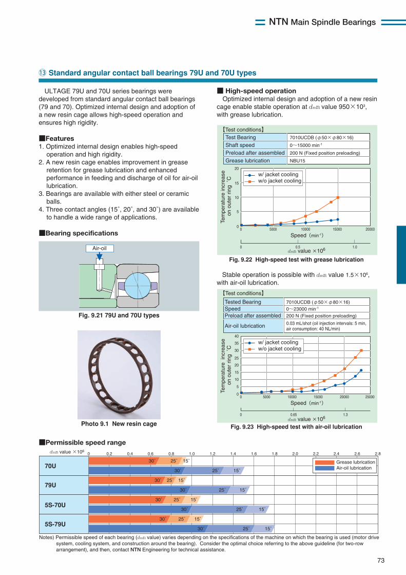
NTN Main Spindle Bearings
73
ULTAGE 79U and 70U series bearings weredeveloped from standard angular contact ball bearings(79 and 70). Optimized internal design and adoption ofa new resin cage allows high-speed operation andensures high rigidity.
■Features1. Optimized internal design enables high-speed
operation and high rigidity.2. A new resin cage enables improvement in grease
retention for grease lubrication and enhancedperformance in feeding and discharge of oil for air-oillubrication.
3. Bearings are available with either steel or ceramicballs.
4. Three contact angles (15˚, 20˚, and 30˚) are availableto handle a wide range of applications.
■Bearing specifications
!3 Standard angular contact ball bearings 79U and 70U types
Fig. 9.21 79U and 70U types
■Permissible speed range
■ High-speed operationOptimized internal design and adoption of a new resin
cage enable stable operation at dmn value 950×103,with grease lubrication.
70U
79U
5S-70U
5S-79U
0 0.2 0.4 0.6 0.8 1.0 1.2 1.4 1.6 1.8 2.0 2.2 2.4 2.6 2.8
30˚ 25˚ 15˚
30˚ 25˚ 15˚
30˚ 25˚ 15˚
30˚ 25˚ 15˚
30˚ 25˚ 15˚
30˚ 25˚ 15˚
30˚ 25˚ 15˚
30˚ 25˚ 15˚
Grease lubrication Air-oil lubrication
Notes) Permissible speed of each bearing (dmn value) varies depending on the specifications of the machine on which the bearing is used (motor drive system, cooling system, and construction around the bearing). Consider the optimal choice referring to the above guideline (for two-row arrangement), and then, contact NTN Engineering for technical assistance.
dmn value ×106
Photo 9.1 New resin cage
Air-oil
Tem
pera
ture
incr
ease
on
out
er r
ing
˚C
Tem
pera
ture
inc
reas
e on
out
er r
ing
˚C
Test Bearing Shaft speedPreload after assembledGrease lubrication
7010UCDB (φ50×φ80×16)
0~15000 min-1
200 N (Fixed position preloading)
NBU15
【Test conditions】
【Test conditions】
Tested Bearing SpeedPreload after assembled
Air-oil lubrication
7010UCDB (φ50×φ80×16)0~23000 min-1
200 N (Fixed position preloading)
Fig. 9.22 High-speed test with grease lubrication
Fig. 9.23 High-speed test with air-oil lubrication
Stable operation is possible with dmn value 1.5×10⁶, with air-oil lubrication.
0.03 mL/shot (oil injection intervals: 5 min, air consumption: 40 NL/min)
0
0 0.5 1.0
5000 10000 20000150000
5
10
15
20
Speed(min-1)
dmn value ×106
w/o jacket coolingw/ jacket cooling
0
0 0.65 1.3
5000 10000 20000 25000150000
5
10
15
20
25
40
35
30
Speed(min-1)
dmn value ×106
w/o jacket coolingw/ jacket cooling
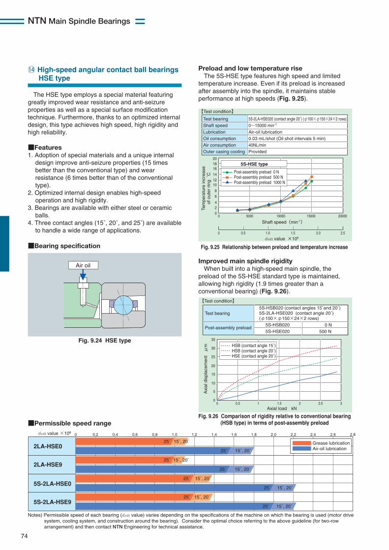
NTN Main Spindle Bearings
74
The HSE type employs a special material featuringgreatly improved wear resistance and anti-seizureproperties as well as a special surface modificationtechnique. Furthermore, thanks to an optimized internaldesign, this type achieves high speed, high rigidity andhigh reliability.
■Features1. Adoption of special materials and a unique internal
design improve anti-seizure properties (15 timesbetter than the conventional type) and wearresistance (6 times better than of the conventionaltype).
2. Optimized internal design enables high-speedoperation and high rigidity.
3. Bearings are available with either steel or ceramicballs.
4. Three contact angles (15˚, 20˚, and 25˚) are availableto handle a wide range of applications.
■Bearing specification
!4 High-speed angular contact ball bearingsHSE type
Fig. 9.24 HSE type
■Permissible speed range
Preload and low temperature riseThe 5S-HSE type features high speed and limited
temperature increase. Even if its preload is increasedafter assembly into the spindle, it maintains stableperformance at high speeds (Fig. 9.25).
Improved main spindle rigidityWhen built into a high-speed main spindle, the
preload of the 5S-HSE standard type is maintained,allowing high rigidity (1.9 times greater than aconventional bearing) (Fig. 9.26).
2LA-HSE0
2LA-HSE9
5S-2LA-HSE0
5S-2LA-HSE9
0 0.2 0.4 0.6 0.8 1.0 1.2 1.4 1.6 1.8 2.0 2.2 2.4 2.6 2.8
25˚ 15˚, 20˚
25˚ 15˚, 20˚
25˚ 15˚, 20˚
25˚ 15˚, 20˚
25˚ 15˚, 20˚
25˚ 15˚, 20˚
25˚ 15˚, 20˚
25˚ 15˚, 20˚
Grease lubrication Air-oil lubrication
Notes) Permissible speed of each bearing (dmn value) varies depending on the specifications of the machine on which the bearing is used (motor drive system, cooling system, and construction around the bearing). Consider the optimal choice referring to the above guideline (for two-row arrangement) and then contact NTN Engineering for technical assistance.
dmn value ×106
Air oil
Fig. 9.25 Relationship between preload and temperature increase
Test bearingShaft speedLubricationOil consumptionAir consumptionOuter casing cooling
5S-2LA-HSE020 (contact angle 20˚) (φ100×φ150×24×2 rows)0~15000 min-1
Air-oil lubrication0.03 mL/shot (Oil shot intervals 5 min)40NL/minProvided
【Test condition】
0
0 0.5 1.0 1.5 2.0 2.5
5000 10000 2000015000
161820
101214
68
024
Shaft speed(min-1)
dmn value ×106
Tem
pera
ture
incr
ease
of o
uter
rin
g ˚
C Post-assembly preload 0 NPost-assembly preload 500 NPost-assembly preload 1000 N
5S-HSE type
Fig. 9.26 Comparison of rigidity relative to conventional bearing(HSB type) in terms of post-assembly preload
0 0.5 1 2 2.5 31.50
5
10
15
20
25
30
35
Axial load kN
Axi
al d
ispl
acem
ent
μm HSB (contact angle 15˚)
HSB (contact angle 20˚)HSE (contact angle 20˚)
Test bearing
Post-assembly preload
5S-HSB020 (contact angles 15˚and 20˚)5S-2LA-HSE020 (contact angle 20˚)(φ100×φ150×24×2 rows) 5S-HSB020 5S-HSE020
0 N500 N
【Test condition】
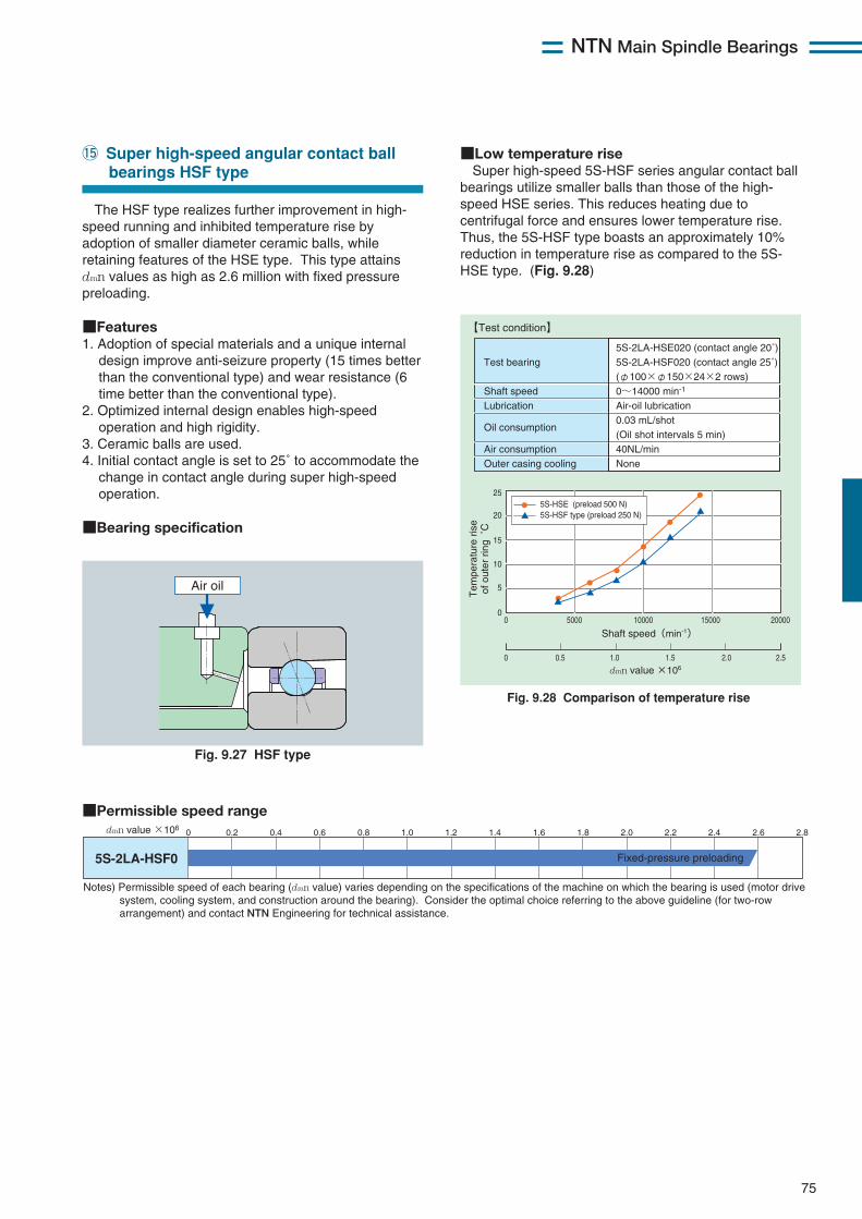
NTN Main Spindle Bearings
75
The HSF type realizes further improvement in high-speed running and inhibited temperature rise byadoption of smaller diameter ceramic balls, whileretaining features of the HSE type. This type attainsdmn values as high as 2.6 million with fixed pressurepreloading.
■Features1. Adoption of special materials and a unique internal
design improve anti-seizure property (15 times betterthan the conventional type) and wear resistance (6time better than the conventional type).
2. Optimized internal design enables high-speedoperation and high rigidity.
3. Ceramic balls are used.4. Initial contact angle is set to 25˚ to accommodate the
change in contact angle during super high-speedoperation.
■Bearing specification
!5 Super high-speed angular contact ball bearings HSF type
■Low temperature riseSuper high-speed 5S-HSF series angular contact ball
bearings utilize smaller balls than those of the high-speed HSE series. This reduces heating due tocentrifugal force and ensures lower temperature rise.Thus, the 5S-HSF type boasts an approximately 10%reduction in temperature rise as compared to the 5S-HSE type. (Fig. 9.28)
■Permissible speed range
5S-2LA-HSF0
0 0.2 0.4 0.6 0.8 1.0 1.2 1.4 1.6 1.8 2.0 2.2 2.4 2.6 2.8
Notes) Permissible speed of each bearing (dmn value) varies depending on the specifications of the machine on which the bearing is used (motor drive system, cooling system, and construction around the bearing). Consider the optimal choice referring to the above guideline (for two-row arrangement) and contact NTN Engineering for technical assistance.
dmn value ×106
Fixed-pressure preloading
Fig. 9.27 HSF type
Air oil
Fig. 9.28 Comparison of temperature rise
【Test condition】
Test bearing
Shaft speedLubrication
Oil consumption
Air consumptionOuter casing cooling
5S-2LA-HSE020 (contact angle 20˚)5S-2LA-HSF020 (contact angle 25˚)(φ100×φ150×24×2 rows)0~14000 min-1
Air-oil lubrication0.03 mL/shot(Oil shot intervals 5 min)40NL/minNone
0
0 0.5 1.0 1.5 2.0 2.5
5000 10000 2000015000
25
20
15
5
0
10
Shaft speed(min-1)
dmn value ×106
Tem
pera
ture
ris
eof
out
er r
ing
˚C
5S-HSE (preload 500 N)5S-HSF type (preload 250 N)
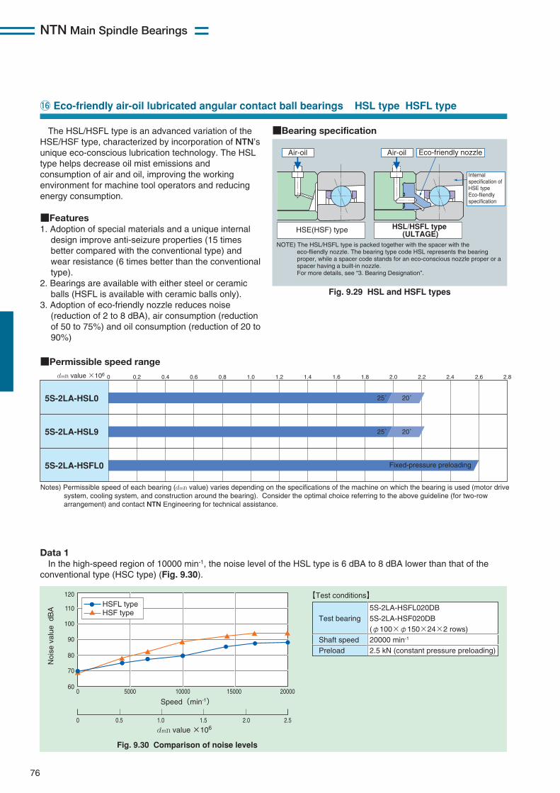
NTN Main Spindle Bearings
The HSL/HSFL type is an advanced variation of theHSE/HSF type, characterized by incorporation of NTN’sunique eco-conscious lubrication technology. The HSLtype helps decrease oil mist emissions andconsumption of air and oil, improving the workingenvironment for machine tool operators and reducingenergy consumption.
■Features1. Adoption of special materials and a unique internal
design improve anti-seizure properties (15 timesbetter compared with the conventional type) andwear resistance (6 times better than the conventionaltype).
2. Bearings are available with either steel or ceramicballs (HSFL is available with ceramic balls only).
3. Adoption of eco-friendly nozzle reduces noise(reduction of 2 to 8 dBA), air consumption (reductionof 50 to 75%) and oil consumption (reduction of 20 to90%)
76
!6 Eco-friendly air-oil lubricated angular contact ball bearings HSL type HSFL type
Fig. 9.29 HSL and HSFL types
■Permissible speed range
Data 1In the high-speed region of 10000 min-1, the noise level of the HSL type is 6 dBA to 8 dBA lower than that of the
conventional type (HSC type) (Fig. 9.30).
5S-2LA-HSL0
5S-2LA-HSL9
5S-2LA-HSFL0
0 0.2 0.4 0.6 0.8 1.0 1.2 1.4 1.6 1.8 2.0 2.2 2.4 2.6 2.8
25˚ 20˚
25˚ 20˚
Notes) Permissible speed of each bearing (dmn value) varies depending on the specifications of the machine on which the bearing is used (motor drive system, cooling system, and construction around the bearing). Consider the optimal choice referring to the above guideline (for two-row arrangement) and contact NTN Engineering for technical assistance.
dmn value ×106
Fixed-pressure preloading
Air-oil Air-oil Eco-friendly nozzle
HSE(HSF) type HSL/HSFL type (ULTAGE)
NOTE) The HSL/HSFL type is packed together with the spacer with the eco-fliendly nozzle. The bearing type code HSL represents the bearing proper, while a spacer code stands for an eco-conscious nozzle proper or a spacer having a built-in nozzle. For more details, see “3. Bearing Designation”.
Internal specification of HSE type Eco-fliendly specification
■Bearing specification
0
0 0.5 1.0 1.5 2.0 2.5
5000 10000 200001500060
70
80
90
100
110
120
Speed(min-1)
Fig. 9.30 Comparison of noise levels
dmn value ×106
Noi
se v
alue
dB
A HSF typeHSFL type
Test bearing
Shaft speedPreload
5S-2LA-HSFL020DB5S-2LA-HSF020DB(φ100×φ150×24×2 rows)20000 min-1 2.5 kN (constant pressure preloading)
【Test conditions】
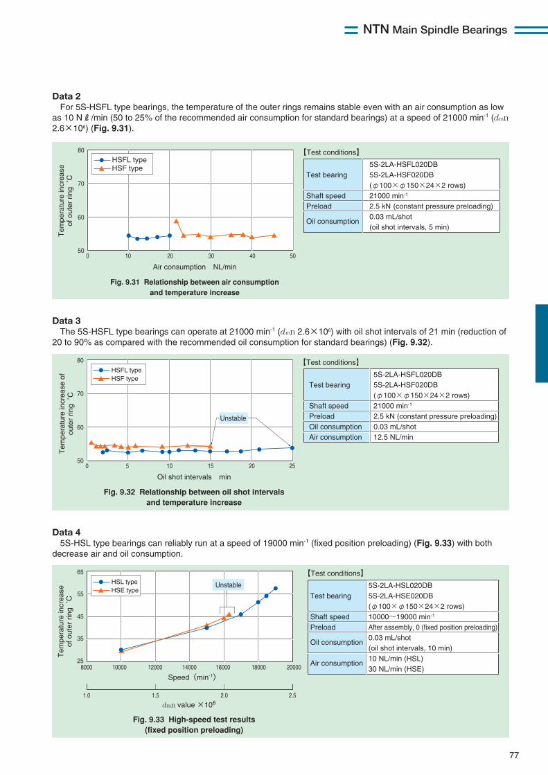
NTN Main Spindle Bearings
77
Data 2For 5S-HSFL type bearings, the temperature of the outer rings remains stable even with an air consumption as low
as 10 NR/min (50 to 25% of the recommended air consumption for standard bearings) at a speed of 21000 min-1 (dmn2.6×106) (Fig. 9.31).
0 10 30 40 502050
60
70
80
Air consumption NL/min
Fig. 9.31 Relationship between air consumptionand temperature increase
Tem
pera
ture
incr
ease
of o
uter
rin
g ˚
C Test bearing
Shaft speedPreload
Oil consumption
5S-2LA-HSFL020DB5S-2LA-HSF020DB(φ100×φ150×24×2 rows)21000 min-1
2.5 kN (constant pressure preloading)0.03 mL/shot(oil shot intervals, 5 min)
【Test conditions】
HSF typeHSFL type
Data 3The 5S-HSFL type bearings can operate at 21000 min-1 (dmn 2.6×10⁶) with oil shot intervals of 21 min (reduction of
20 to 90% as compared with the recommended oil consumption for standard bearings) (Fig. 9.32).
0 5 15 20 251050
60
70
80
Oil shot intervals min
Fig. 9.32 Relationship between oil shot intervalsand temperature increase
Tem
pera
ture
incr
ease
of
oute
r rin
g ˚
C
Test bearing
Shaft speedPreloadOil consumptionAir consumption
5S-2LA-HSFL020DB5S-2LA-HSF020DB(φ100×φ150×24×2 rows)21000 min-1
2.5 kN (constant pressure preloading)0.03 mL/shot12.5 NL/min
【Test conditions】
HSF typeHSFL type
Unstable
Data 45S-HSL type bearings can reliably run at a speed of 19000 min-1 (fixed position preloading) (Fig. 9.33) with both
decrease air and oil consumption.
1.0 1.5 2.0 2.5
8000 10000 14000 16000 18000 2000012000
65
55
45
35
25
Speed(min-1)
Fig. 9.33 High-speed test results(fixed position preloading)
dmn value ×106
Tem
pera
ture
incr
ease
of o
uter
rin
g ˚
C Test bearing
Shaft speedPreload
Oil consumption
Air consumption
5S-2LA-HSL020DB5S-2LA-HSE020DB(φ100×φ150×24×2 rows)10000~19000 min-1
After assembly, 0 (fixed position preloading)0.03 mL/shot(oil shot intervals, 10 min)10 NL/min (HSL)30 NL/min (HSE)
【Test conditions】
HSE typeHSL type Unstable
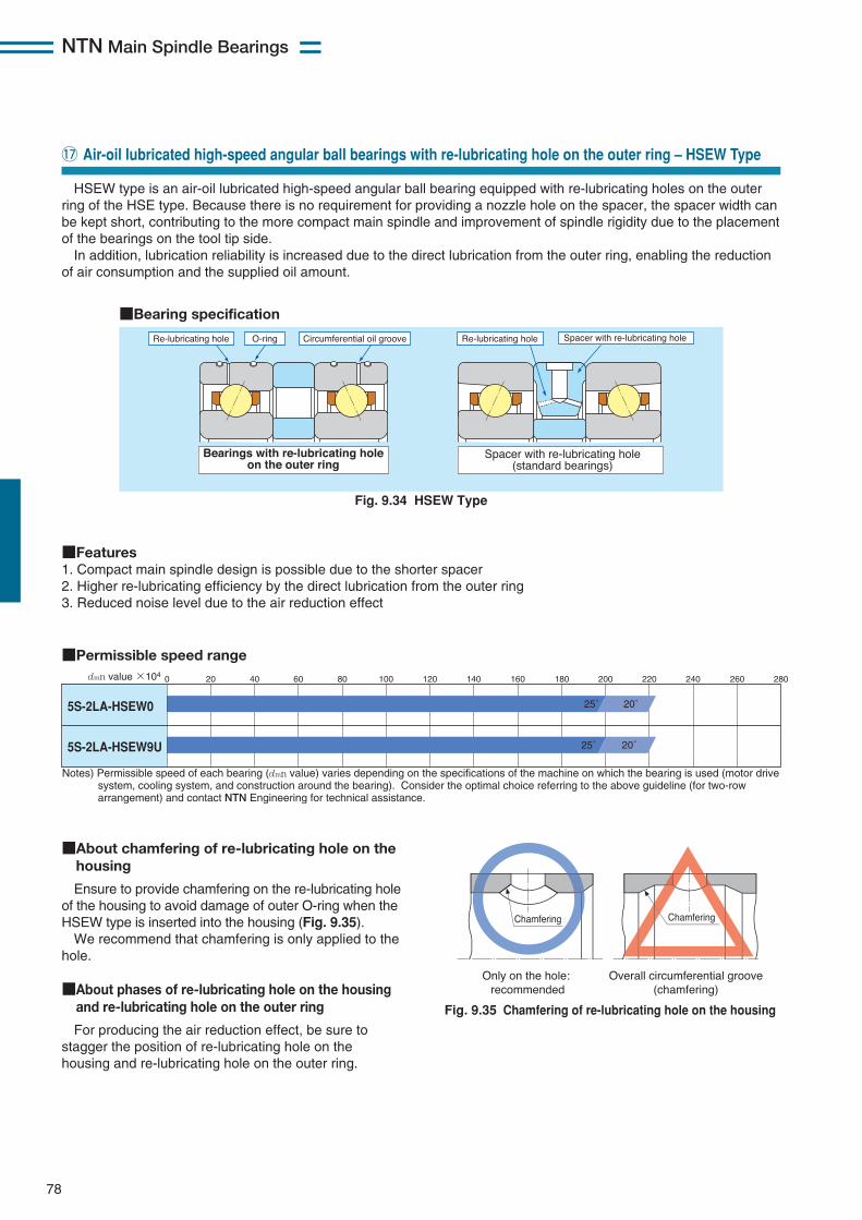
78
NTN Main Spindle Bearings
!7 Air-oil lubricated high-speed angular ball bearings with re-lubricating hole on the outer ring – HSEW Type
HSEW type is an air-oil lubricated high-speed angular ball bearing equipped with re-lubricating holes on the outerring of the HSE type. Because there is no requirement for providing a nozzle hole on the spacer, the spacer width canbe kept short, contributing to the more compact main spindle and improvement of spindle rigidity due to the placementof the bearings on the tool tip side. In addition, lubrication reliability is increased due to the direct lubrication from the outer ring, enabling the reduction
of air consumption and the supplied oil amount.
Fig. 9.34 HSEW Type
Fig. 9.35 Chamfering of re-lubricating hole on the housing
■Permissible speed range
Notes) Permissible speed of each bearing (dmn value) varies depending on the specifications of the machine on which the bearing is used (motor drive system, cooling system, and construction around the bearing). Consider the optimal choice referring to the above guideline (for two-row arrangement) and contact NTN Engineering for technical assistance.
5S-2LA-HSEW0
5S-2LA-HSEW9U
0dmn value ×104 20 40 60 80 100 120 140 160 180 200 220 240 260 280
25˚ 20˚
25˚ 20˚
Re-lubricating hole Re-lubricating hole Spacer with re-lubricating holeO-ring
Spacer with re-lubricating hole(standard bearings)
Circumferential oil groove
Bearings with re-lubricating holeon the outer ring
■Bearing specification
■Features1. Compact main spindle design is possible due to the shorter spacer2. Higher re-lubricating efficiency by the direct lubrication from the outer ring3. Reduced noise level due to the air reduction effect
■About chamfering of re-lubricating hole on thehousing
Ensure to provide chamfering on the re-lubricating holeof the housing to avoid damage of outer O-ring when theHSEW type is inserted into the housing (Fig. 9.35).We recommend that chamfering is only applied to the
hole.
■About phases of re-lubricating hole on the housingand re-lubricating hole on the outer ring
For producing the air reduction effect, be sure tostagger the position of re-lubricating hole on thehousing and re-lubricating hole on the outer ring.
Chamfering
Only on the hole: recommended
Overall circumferential groove(chamfering)
Chamfering
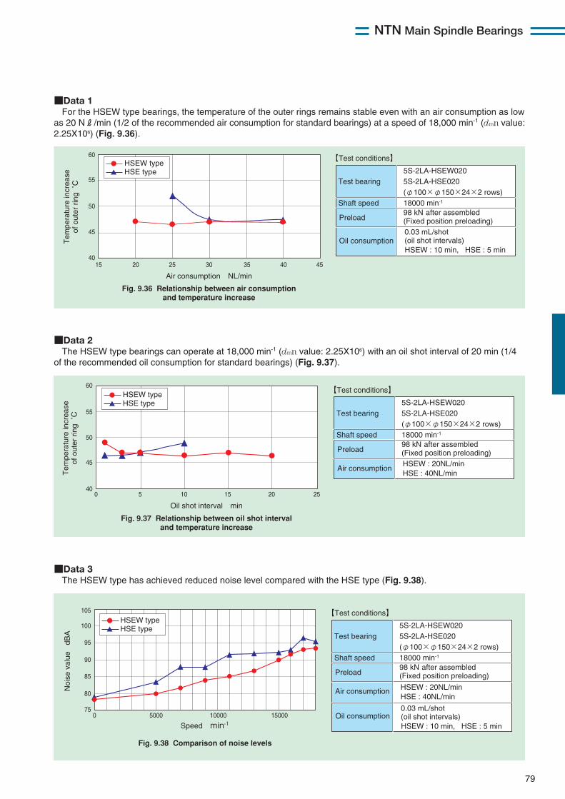
79
NTN Main Spindle Bearings
■Data 3The HSEW type has achieved reduced noise level compared with the HSE type (Fig. 9.38).
0 5000 10000 1500075
80
85
90
95
100
105
Speed min-1
Noi
se v
alue
dB
A
HSE typeHSEW type
Fig. 9.38 Comparison of noise levels
Test bearing
Shaft speed
5S-2LA-HSEW0205S-2LA-HSE020(φ100×φ150×24×2 rows)18000 min-1
【Test conditions】
HSEW : 20NL/minHSE : 40NL/min
98 kN after assembled(Fixed position preloading)Preload
Air consumption
HSEW : 10 min, HSE : 5 min
0.03 mL/shot(oil shot intervals)Oil consumption
■Data 1For the HSEW type bearings, the temperature of the outer rings remains stable even with an air consumption as low
as 20 NR/min (1/2 of the recommended air consumption for standard bearings) at a speed of 18,000 min-1 (dmn value:2.25X10⁶) (Fig. 9.36).
15 20 30 35 40 452540
45
50
60
55
Air consumption NL/min
Fig. 9.36 Relationship between air consumptionand temperature increase
Tem
pera
ture
incr
ease
of o
uter
rin
g ˚
C
HSE typeHSEW type
Test bearing
Shaft speed
5S-2LA-HSEW0205S-2LA-HSE020(φ100×φ150×24×2 rows)18000 min-1
【Test conditions】
HSEW : 10 min, HSE : 5 min
0.03 mL/shot(oil shot intervals)
98 kN after assembled(Fixed position preloading)Preload
Oil consumption
■Data 2The HSEW type bearings can operate at 18,000 min-1 (dmn value: 2.25X10⁶) with an oil shot interval of 20 min (1/4
of the recommended oil consumption for standard bearings) (Fig. 9.37).
0 5 15 20 251040
45
50
55
60
Oil shot interval min
Fig. 9.37 Relationship between oil shot intervaland temperature increase
HSE typeHSEW type
Tem
pera
ture
incr
ease
of o
uter
rin
g ˚
C Test bearing
Shaft speed
5S-2LA-HSEW0205S-2LA-HSE020(φ100×φ150×24×2 rows)18000 min-1
【Test conditions】
HSEW : 20NL/minHSE : 40NL/min
98 kN after assembled(Fixed position preloading)Preload
Air consumption
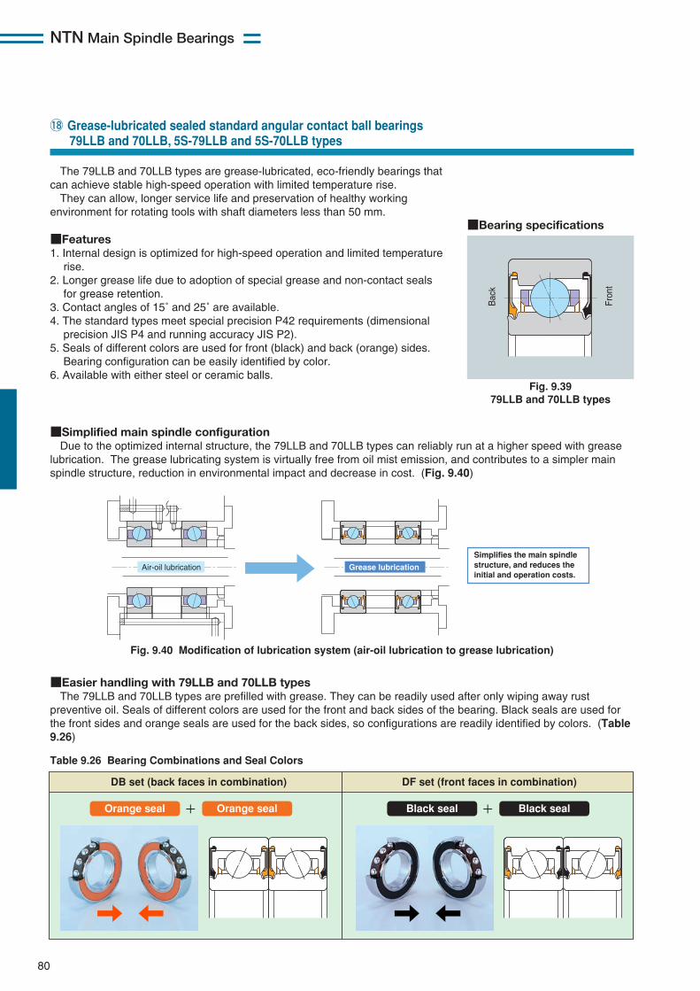
NTN Main Spindle Bearings
80
The 79LLB and 70LLB types are grease-lubricated, eco-friendly bearings thatcan achieve stable high-speed operation with limited temperature rise.They can allow, longer service life and preservation of healthy working
environment for rotating tools with shaft diameters less than 50 mm.
■Features1. Internal design is optimized for high-speed operation and limited temperature
rise.2. Longer grease life due to adoption of special grease and non-contact seals
for grease retention.3. Contact angles of 15˚ and 25˚ are available.4. The standard types meet special precision P42 requirements (dimensional
precision JIS P4 and running accuracy JIS P2).5. Seals of different colors are used for front (black) and back (orange) sides.
Bearing configuration can be easily identified by color.6. Available with either steel or ceramic balls.
!8 Grease-lubricated sealed standard angular contact ball bearings79LLB and 70LLB, 5S-79LLB and 5S-70LLB types
Fig. 9.3979LLB and 70LLB types
Bac
k Fr
ont
■Bearing specifications
■Simplified main spindle configurationDue to the optimized internal structure, the 79LLB and 70LLB types can reliably run at a higher speed with grease
lubrication. The grease lubricating system is virtually free from oil mist emission, and contributes to a simpler mainspindle structure, reduction in environmental impact and decrease in cost. (Fig. 9.40)
Fig. 9.40 Modification of lubrication system (air-oil lubrication to grease lubrication)
Air-oil lubrication Grease lubrication
Simplifies the main spindle structure, and reduces the initial and operation costs.
■Easier handling with 79LLB and 70LLB typesThe 79LLB and 70LLB types are prefilled with grease. They can be readily used after only wiping away rust
preventive oil. Seals of different colors are used for the front and back sides of the bearing. Black seals are used forthe front sides and orange seals are used for the back sides, so configurations are readily identified by colors. (Table9.26)
Table 9.26 Bearing Combinations and Seal Colors
DB set (back faces in combination)
+
DF set (front faces in combination)
Orange seal Orange seal + Black seal Black seal
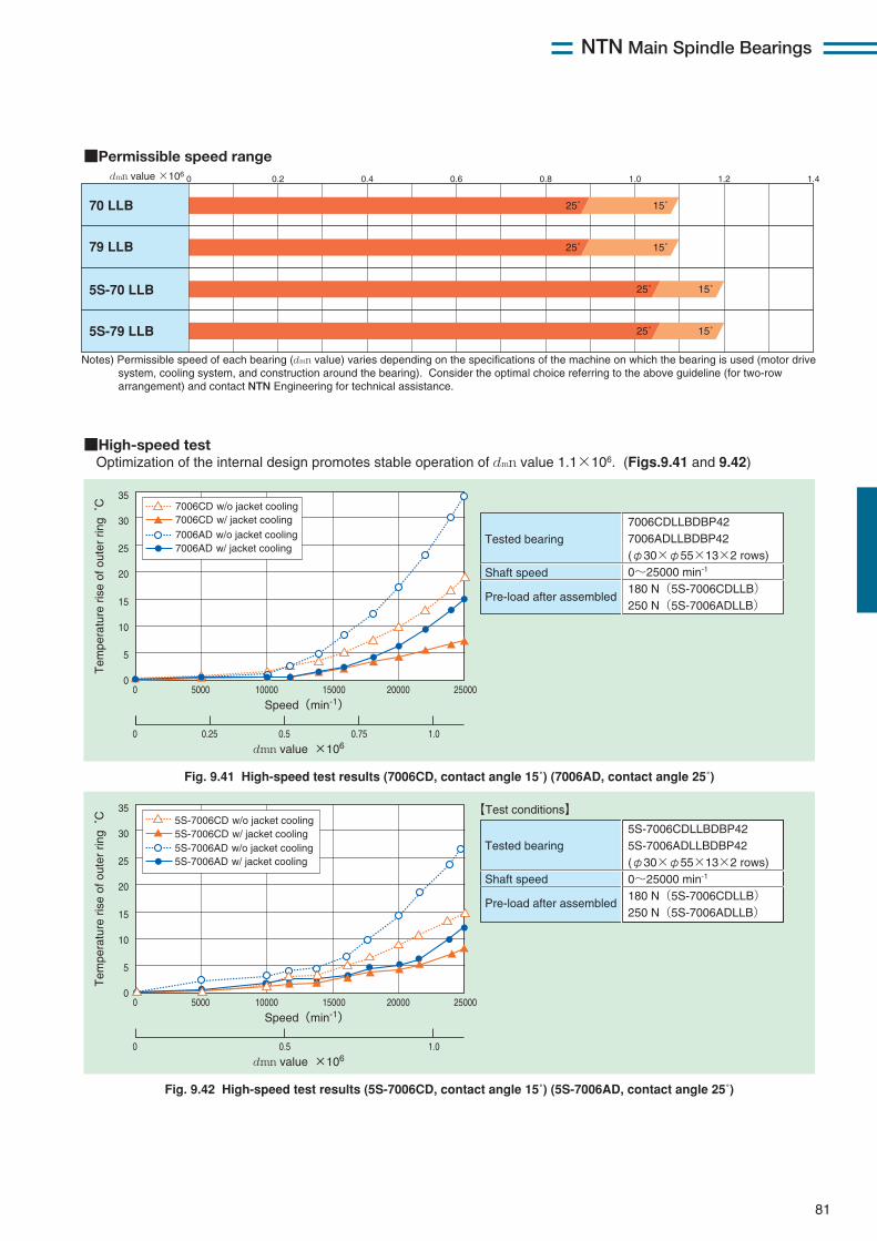
NTN Main Spindle Bearings
81
■High-speed testOptimization of the internal design promotes stable operation of dmn value 1.1×10⁶. (Figs.9.41 and 9.42)
Fig. 9.41 High-speed test results (7006CD, contact angle 15˚) (7006AD, contact angle 25˚)
Tested bearing
Shaft speed
Pre-load after assembled
7006CDLLBDBP427006ADLLBDBP42(φ30×φ55×13×2 rows)0~25000 min-1
180 N(5S-7006CDLLB)250 N(5S-7006ADLLB)
0 15000 20000 250005000 10000
35
30
25
20
15
10
5
0
Fig. 9.42 High-speed test results (5S-7006CD, contact angle 15˚) (5S-7006AD, contact angle 25˚)
0 0.5 1.0
Speed(min-1)
dmn value ×106
Tem
pera
ture
ris
e of
out
er r
ing
˚C
Tested bearing
Shaft speed
Pre-load after assembled
5S-7006CDLLBDBP425S-7006ADLLBDBP42(φ30×φ55×13×2 rows)0~25000 min-1
180 N(5S-7006CDLLB)250 N(5S-7006ADLLB)
【Test conditions】
5S-7006CD w/ jacket cooling5S-7006CD w/o jacket cooling
5S-7006AD w/ jacket cooling5S-7006AD w/o jacket cooling
0 15000 20000 250005000 10000
35
30
25
20
15
10
5
0
0 0.25 0.750.5 1.0
Speed(min-1)
dmn value ×106
Tem
pera
ture
ris
e of
out
er r
ing
˚C
7006AD w/ jacket cooling7006AD w/o jacket cooling7006CD w/ jacket cooling7006CD w/o jacket cooling
■Permissible speed range
70 LLB
79 LLB
5S-70 LLB
5S-79 LLB
0 0.2 0.4 0.6 0.8 1.0 1.2 1.4
25˚ 15˚
25˚ 15˚
25˚ 15˚
25˚ 15˚
Notes) Permissible speed of each bearing (dmn value) varies depending on the specifications of the machine on which the bearing is used (motor drive system, cooling system, and construction around the bearing). Consider the optimal choice referring to the above guideline (for two-row arrangement) and contact NTN Engineering for technical assistance.
dmn value ×106

NTN Main Spindle Bearings
82
By the optimized material and internal structure, BNS LLB typebearings have excellent performance at higher speeds. This helps toreduce pollution and cost.
■Features1. Adoption of special materials and unique internal design improve
anti-seizure properties (15 times better than the conventional type)and wear resistance (6 times better than the conventional type).
2. Optimized internal design enables high-speed operation and highrigidity.
3. Available with either steel or ceramic balls.4. Adoption of grease pockets, special grease, and non-contact seals
improves service life of the grease.
!8 Grease-lubricated sealed angular contact ball bearings BNS LLB and 5S-2LA-BNS LLB types
Fig. 9.43 BNS LLB type
■Bearing specification
■Simplified main spindle configurationBNS LLB type bearings can reliably operate at a higher speed with grease lubrication. The grease lubrication
system is virtually free from oil mist emission can simplify the main spindle structure, reduce pollution and decreasecost (Fig. 9.44).
Fig. 9.44 Modification of lubrication system (air-oil lubrication to grease lubrication)
Simplifies the main spindle structure and reduces the initial and operating costs.
Air-oil lubrication Grease lubrication
Capable of replacing air-oil lubricated bearings up to dmn value of 1,400,000.
■Easier handling with BNS LLB typeThe BNS LLB type has been packed with grease in advance. They can be used after wiping away rust preventive
oil . Seals in different colors are used for the front and back sides of the bearings. Black seals are used for the frontsides and orange seals are used for the back sides, so configurations can be easily identified by color. (Table 9.27)
Table 9.27 Bearing Combinations and Seal Colors
DB set (back faces in combination)
+
DF set (front faces in combination)
Orange seal Orange seal + Black seal Black seal
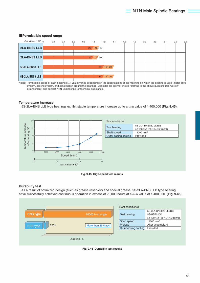
NTN Main Spindle Bearings
83
■Permissible speed range
2LA-BNS0 LLB
2LA-BNS9 LLB
5S-2LA-BNS0 LLB
5S-2LA-BNS9 LLB
0 0.2 0.4 0.6 0.8 1.0 1.2 1.4 1.6 1.8 2.0 2.2 2.4 2.6 2.8
25˚ 15˚, 20˚
25˚ 15˚, 20˚
25˚ 15˚, 20˚
25˚ 15˚, 20˚
Notes) Permissible speed of each bearing (dmn value) varies depending on the specifications of the machine on which the bearing is used (motor drive system, cooling system, and construction around the bearing). Consider the optimal choice referring to the above guideline (for two-row arrangement) and contact NTN Engineering for technical assistance.
dmn value ×106
Test bearing
Shaft speedPreloadOuter casing cooling
5S-2LA-BNS020 LLBDB5S-HSB020C(φ100×φ150×24×2 rows)11000 min-1
After assembly, 0Provided
【Test conditions】
【Test conditions】
Duration, h
20000 h or longer
650h
BNS type
HSB type More than 25 times
0
0 0.5 1.0 1.5
2000 4000 8000 10000 1200060000
5
10
15
20
Speed(min-1)
dmn value ×106
Tem
pera
ture
incr
ease
of o
uter
rin
g ˚
C Test bearing
Shaft speedOuter casing cooling
5S-2LA-BNS020 LLBDB(φ100×φ150×24×2 rows)11000 min-1
Provided
Fig. 9.45 High-speed test results
Fig. 9.46 Durability test results
Durability test As a result of optimized design (such as grease reservoir) and special grease, 5S-2LA-BNS LLB type bearing have successfully achieved continuous operation in excess of 20,000 hours at a dmn value of 1,400,000 (Fig. 9.46).
■データ1/温度上昇 5S-2LA-BNSタイプはdmn値140万の高速領域まで安定した温度上昇を示します。(図9.39)
Temperature increase 5S-2LA-BNS LLB type bearings exhibit stable temperature increase up to a dmn value of 1,400,000 (Fig. 9.45).
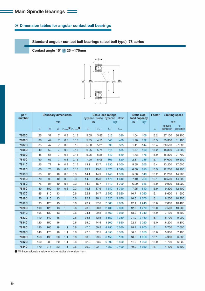
Main Spindle Bearings
84
@00 Dimension tables for angular contact ball bearings
φD φD1 φD2φd φd1
B
a
r
r r1
r
7805C 25 37 7 0.3 0.15 5.05 3.85 515 390 1.04 106 16.2 27 100 36 100
7806C 30 42 7 0.3 0.15 5.35 4.50 545 460 1.20 122 16.5 23 300 31 100
7807C 35 47 7 0.3 0.15 5.80 5.25 590 535 1.41 144 16.4 20 500 27 300
7808C 40 52 7 0.3 0.15 6.05 5.75 615 585 1.57 160 16.2 18 300 24 300
7809C 45 58 7 0.3 0.15 6.25 6.25 640 640 1.73 176 16.0 16 300 21 700
7810C 50 65 7 0.3 0.15 7.90 8.05 805 820 2.31 236 16.1 14 600 19 500
7811C 55 72 9 0.3 0.15 13.1 12.7 1 330 1 300 5.55 565 16.4 13 200 17 600
7812C 60 78 10 0.3 0.15 13.4 13.6 1 370 1 390 6.00 610 16.3 12 200 16 200
7813C 65 85 10 0.6 0.3 14.1 14.9 1 440 1 520 5.30 540 16.2 11 200 14 900
7814C 70 90 10 0.6 0.3 14.5 15.8 1 470 1 610 7.10 720 16.1 10 500 14 000
7815C 75 95 10 0.6 0.3 14.8 16.7 1 510 1 700 6.00 615 16.0 9 900 13 200
7816C 80 100 10 0.6 0.3 15.1 17.6 1 540 1 790 7.95 810 15.9 9 300 12 400
7817C 85 110 13 1 0.6 22.1 24.7 2 250 2 520 10.7 1 090 16.1 8 600 11 500
7818C 90 115 13 1 0.6 22.7 26.1 2 320 2 670 10.5 1 070 16.1 8 200 10 900
7819C 95 120 13 1 0.6 23.4 27.6 2 380 2 820 12.1 1 240 16.0 7 800 10 400
7820C 100 125 13 1 0.6 23.5 28.3 2 400 2 890 12.5 1 270 16.0 7 500 10 000
7821C 105 130 13 1 0.6 24.1 29.8 2 460 3 050 13.2 1 340 15.9 7 100 9 500
7822C 110 140 16 1 0.6 34.5 42.5 3 550 4 350 21.0 2 140 16.1 6 700 9 000
7824C 120 150 16 1 0.6 35.0 44.5 3 600 4 550 22.1 2 260 16.0 6 200 8 300
7826C 130 165 18 1.1 0.6 47.0 59.5 4 750 6 050 28.4 2 900 16.1 5 700 7 600
7828C 140 175 18 1.1 0.6 47.5 62.5 4 850 6 350 30.0 3 050 16.0 5 300 7 100
7830C 150 190 20 1.1 0.6 60.5 79.5 6 150 8 100 48.5 4 950 16.1 4 900 6 600
7832C 160 200 20 1.1 0.6 62.0 83.5 6 300 8 500 41.0 4 200 16.0 4 700 6 200
7834C 170 215 22 1.1 0.6 76.0 102 7 750 10 400 49.0 4 950 16.1 4 400 5 800
part Boundary dimensions Basic load ratings Static axial Factor Limiting speednumber dynamic static dynamic static load capacity
mm kN kgf kN kgf min-1
grease oild D B rs min1 r1s min1 Cr Cor Cr Cor fo lubrication lubrication
1 Minimum allowable value for corner radius dimension r or r1.
Standard angular contact ball bearings (steel ball type) 78 series
Contact angle 15˚ d 25〜170mm
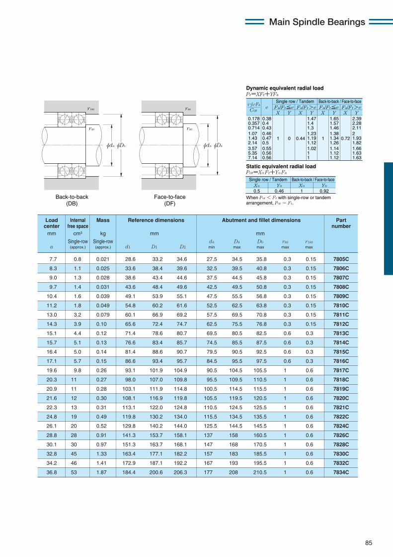
85
0.178 0.357 0.714 1.07 1.43 2.14 3.57 5.35 7.14
eX Y
Dynamic equivalent radial loadPr=XFr+YFa
Static equivalent radial loadPor=Xo Fr+Yo Fa
Fa/Fr≦e Fa/Fr>eSingle row / Tandem Back-to-back / Face-to-face
Fa/Fr≦e Fa/Fr>eX Y X Y X Y
0.38 0.4 0.43 0.46 0.47 0.5 0.55 0.56 0.56
1 0 0.44
1.47 1.4 1.3 1.23 1.19 1.12 1.02 1 1
1
1.65 1.57 1.46 1.38 1.34 1.26 1.14 1.12 1.12
0.72
2.39 2.28 2.11 2 1.93 1.82 1.66 1.63 1.63
Xo
Single row / Tandem Back-to-back / Face-to-face
0.5Yo Xo Yo
0.46 1 0.92
Cor
i・fo・Fa
When Por < Fr with single-row or tandem arrangement, Por = Fr.
φDbφda
ras
r1as
φDaφda
ras
ras
Back-to-back (DB)
Face-to-face (DF)
7.7 0.8 0.021 28.6 33.2 34.6 27.5 34.5 35.8 0.3 0.15 7805C
8.3 1.1 0.025 33.6 38.4 39.6 32.5 39.5 40.8 0.3 0.15 7806C
9.0 1.3 0.028 38.6 43.4 44.6 37.5 44.5 45.8 0.3 0.15 7807C
9.7 1.4 0.031 43.6 48.4 49.6 42.5 49.5 50.8 0.3 0.15 7808C
10.4 1.6 0.039 49.1 53.9 55.1 47.5 55.5 56.8 0.3 0.15 7809C
11.2 1.8 0.049 54.8 60.2 61.6 52.5 62.5 63.8 0.3 0.15 7810C
13.0 3.2 0.079 60.1 66.9 69.2 57.5 69.5 70.8 0.3 0.15 7811C
14.3 3.9 0.10 65.6 72.4 74.7 62.5 75.5 76.8 0.3 0.15 7812C
15.1 4.4 0.12 71.4 78.6 80.7 69.5 80.5 82.5 0.6 0.3 7813C
15.7 5.1 0.13 76.6 83.4 85.7 74.5 85.5 87.5 0.6 0.3 7814C
16.4 5.0 0.14 81.4 88.6 90.7 79.5 90.5 92.5 0.6 0.3 7815C
17.1 5.7 0.15 86.6 93.4 95.7 84.5 95.5 97.5 0.6 0.3 7816C
19.6 9.8 0.26 93.1 101.9 104.9 90.5 104.5 105.5 1 0.6 7817C
20.3 11 0.27 98.0 107.0 109.8 95.5 109.5 110.5 1 0.6 7818C
20.9 11 0.28 103.1 111.9 114.8 100.5 114.5 115.5 1 0.6 7819C
21.6 12 0.30 108.1 116.9 119.8 105.5 119.5 120.5 1 0.6 7820C
22.3 13 0.31 113.1 122.0 124.8 110.5 124.5 125.5 1 0.6 7821C
24.8 19 0.49 119.8 130.2 134.0 115.5 134.5 135.5 1 0.6 7822C
26.1 20 0.52 129.8 140.2 144.0 125.5 144.5 145.5 1 0.6 7824C
28.8 28 0.91 141.3 153.7 158.1 137 158 160.5 1 0.6 7826C
30.1 30 0.97 151.3 163.7 168.1 147 168 170.5 1 0.6 7828C
32.8 45 1.33 163.4 177.1 182.2 157 183 185.5 1 0.6 7830C
34.2 46 1.41 172.9 187.1 192.2 167 193 195.5 1 0.6 7832C
36.8 53 1.87 184.4 200.6 206.3 177 208 210.5 1 0.6 7834C
Load Internal Mass Reference dimensions Abutment and fillet dimensions Part center free space numbermm cm3 kg mm mm
Single-row Single-row da Da Db ras r1asa (approx.) (approx.) d1 D1 D2 min max max max max
Main Spindle Bearings
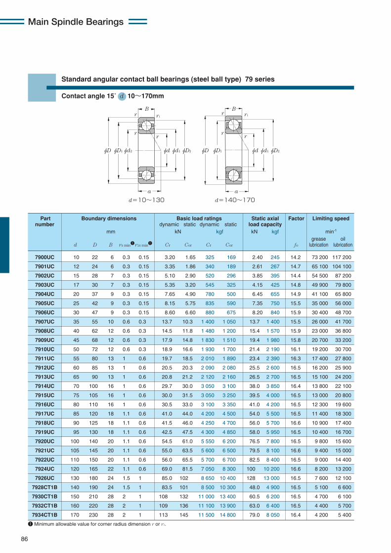
Main Spindle Bearings
86
φD φD1 φD2φd2 φdφd1
B
a
d=10~130 d=140~170
φD φD1 φD2φdφd1
B
a
r1r
rr
r
rr
r1
7900UC 10 22 6 0.3 0.15 3.20 1.65 325 169 2.40 245 14.2 73 200 117 200
7901UC 12 24 6 0.3 0.15 3.35 1.86 340 189 2.61 267 14.7 65 100 104 100
7902UC 15 28 7 0.3 0.15 5.10 2.90 520 296 3.85 395 14.4 54 500 87 200
7903UC 17 30 7 0.3 0.15 5.35 3.20 545 325 4.15 425 14.8 49 900 79 800
7904UC 20 37 9 0.3 0.15 7.65 4.90 780 500 6.45 655 14.9 41 100 65 800
7905UC 25 42 9 0.3 0.15 8.15 5.75 835 590 7.35 750 15.5 35 000 56 000
7906UC 30 47 9 0.3 0.15 8.60 6.60 880 675 8.20 840 15.9 30 400 48 700
7907UC 35 55 10 0.6 0.3 13.7 10.3 1 400 1 050 13.7 1 400 15.5 26 000 41 700
7908UC 40 62 12 0.6 0.3 14.5 11.8 1 480 1 200 15.4 1 570 15.9 23 000 36 800
7909UC 45 68 12 0.6 0.3 17.9 14.8 1 830 1 510 19.4 1 980 15.8 20 700 33 200
7910UC 50 72 12 0.6 0.3 18.9 16.6 1 930 1 700 21.4 2 190 16.1 19 200 30 700
7911UC 55 80 13 1 0.6 19.7 18.5 2 010 1 890 23.4 2 390 16.3 17 400 27 800
7912UC 60 85 13 1 0.6 20.5 20.3 2 090 2 080 25.5 2 600 16.5 16 200 25 900
7913UC 65 90 13 1 0.6 20.8 21.2 2 120 2 160 26.5 2 700 16.5 15 100 24 200
7914UC 70 100 16 1 0.6 29.7 30.0 3 050 3 100 38.0 3 850 16.4 13 800 22 100
7915UC 75 105 16 1 0.6 30.0 31.5 3 050 3 250 39.5 4 000 16.5 13 000 20 800
7916UC 80 110 16 1 0.6 30.5 33.0 3 100 3 350 41.0 4 200 16.5 12 300 19 600
7917UC 85 120 18 1.1 0.6 41.0 44.0 4 200 4 500 54.0 5 500 16.5 11 400 18 300
7918UC 90 125 18 1.1 0.6 41.5 46.0 4 250 4 700 56.0 5 700 16.6 10 900 17 400
7919UC 95 130 18 1.1 0.6 42.5 47.5 4 300 4 850 58.0 5 950 16.5 10 400 16 700
7920UC 100 140 20 1.1 0.6 54.5 61.0 5 550 6 200 76.5 7 800 16.5 9 800 15 600
7921UC 105 145 20 1.1 0.6 55.0 63.5 5 600 6 500 79.5 8 100 16.6 9 400 15 000
7922UC 110 150 20 1.1 0.6 56.0 65.5 5 700 6 700 82.5 8 400 16.5 9 000 14 400
7924UC 120 165 22 1.1 0.6 69.0 81.5 7 050 8 300 100 10 200 16.6 8 200 13 200
7926UC 130 180 24 1.5 1 85.0 102 8 650 10 400 128 13 000 16.5 7 600 12 100
7928CT1B 140 190 24 1.5 1 83.5 101 8 500 10 300 48.0 4 900 16.5 5 100 6 600
7930CT1B 150 210 28 2 1 108 132 11 000 13 400 60.5 6 200 16.5 4 700 6 100
7932CT1B 160 220 28 2 1 109 136 11 100 13 900 63.0 6 400 16.5 4 400 5 700
7934CT1B 170 230 28 2 1 113 145 11 500 14 800 79.0 8 050 16.4 4 200 5 400
Part Boundary dimensions Basic load ratings Static axial Factor Limiting speednumber dynamic static dynamic static load capacity
mm kN kgf kN kgf min-1
grease oild D B rs min1r1s min1 Cr Cor Cr Cor fo lubrication lubrication
1 Minimum allowable value for corner radius dimension r or r1.
Standard angular contact ball bearings (steel ball type) 79 series
Contact angle 15˚ d 10〜170mm
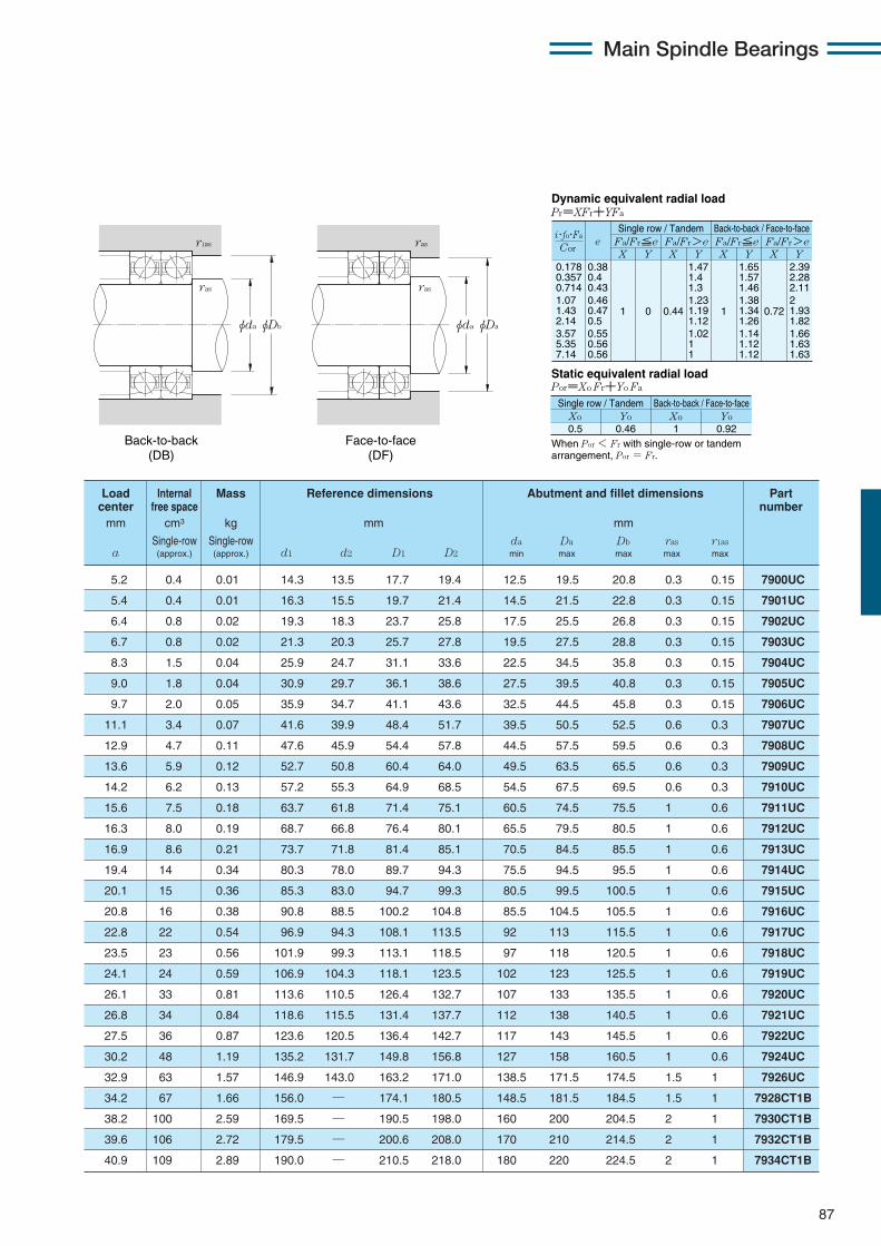
Main Spindle Bearings
87
5.2 0.4 0.01 14.3 13.5 17.7 19.4 12.5 19.5 20.8 0.3 0.15 7900UC
5.4 0.4 0.01 16.3 15.5 19.7 21.4 14.5 21.5 22.8 0.3 0.15 7901UC
6.4 0.8 0.02 19.3 18.3 23.7 25.8 17.5 25.5 26.8 0.3 0.15 7902UC
6.7 0.8 0.02 21.3 20.3 25.7 27.8 19.5 27.5 28.8 0.3 0.15 7903UC
8.3 1.5 0.04 25.9 24.7 31.1 33.6 22.5 34.5 35.8 0.3 0.15 7904UC
9.0 1.8 0.04 30.9 29.7 36.1 38.6 27.5 39.5 40.8 0.3 0.15 7905UC
9.7 2.0 0.05 35.9 34.7 41.1 43.6 32.5 44.5 45.8 0.3 0.15 7906UC
11.1 3.4 0.07 41.6 39.9 48.4 51.7 39.5 50.5 52.5 0.6 0.3 7907UC
12.9 4.7 0.11 47.6 45.9 54.4 57.8 44.5 57.5 59.5 0.6 0.3 7908UC
13.6 5.9 0.12 52.7 50.8 60.4 64.0 49.5 63.5 65.5 0.6 0.3 7909UC
14.2 6.2 0.13 57.2 55.3 64.9 68.5 54.5 67.5 69.5 0.6 0.3 7910UC
15.6 7.5 0.18 63.7 61.8 71.4 75.1 60.5 74.5 75.5 1 0.6 7911UC
16.3 8.0 0.19 68.7 66.8 76.4 80.1 65.5 79.5 80.5 1 0.6 7912UC
16.9 8.6 0.21 73.7 71.8 81.4 85.1 70.5 84.5 85.5 1 0.6 7913UC
19.4 14 0.34 80.3 78.0 89.7 94.3 75.5 94.5 95.5 1 0.6 7914UC
20.1 15 0.36 85.3 83.0 94.7 99.3 80.5 99.5 100.5 1 0.6 7915UC
20.8 16 0.38 90.8 88.5 100.2 104.8 85.5 104.5 105.5 1 0.6 7916UC
22.8 22 0.54 96.9 94.3 108.1 113.5 92 113 115.5 1 0.6 7917UC
23.5 23 0.56 101.9 99.3 113.1 118.5 97 118 120.5 1 0.6 7918UC
24.1 24 0.59 106.9 104.3 118.1 123.5 102 123 125.5 1 0.6 7919UC
26.1 33 0.81 113.6 110.5 126.4 132.7 107 133 135.5 1 0.6 7920UC
26.8 34 0.84 118.6 115.5 131.4 137.7 112 138 140.5 1 0.6 7921UC
27.5 36 0.87 123.6 120.5 136.4 142.7 117 143 145.5 1 0.6 7922UC
30.2 48 1.19 135.2 131.7 149.8 156.8 127 158 160.5 1 0.6 7924UC
32.9 63 1.57 146.9 143.0 163.2 171.0 138.5 171.5 174.5 1.5 1 7926UC
34.2 67 1.66 156.0 — 174.1 180.5 148.5 181.5 184.5 1.5 1 7928CT1B
38.2 100 2.59 169.5 — 190.5 198.0 160 200 204.5 2 1 7930CT1B
39.6 106 2.72 179.5 — 200.6 208.0 170 210 214.5 2 1 7932CT1B
40.9 109 2.89 190.0 — 210.5 218.0 180 220 224.5 2 1 7934CT1B
Load Internal Mass Reference dimensions Abutment and fillet dimensions Part center free space numbermm cm3 kg mm mm
Single-row Single-row da Da Db ras r1asa (approx.) (approx.) d1 d2 D1 D2 min max max max max
φDbφda
ras
r1as
φDaφda
ras
ras
Back-to-back (DB)
Face-to-face (DF)
0.178 0.357 0.714 1.07 1.43 2.14 3.57 5.35 7.14
eX Y
Dynamic equivalent radial loadPr=XFr+YFa
Static equivalent radial loadPor=Xo Fr+Yo Fa
Fa/Fr≦e Fa/Fr>eSingle row / Tandem Back-to-back / Face-to-face
Fa/Fr≦e Fa/Fr>eX Y X Y X Y
0.38 0.4 0.43 0.46 0.47 0.5 0.55 0.56 0.56
1 0 0.44
1.47 1.4 1.3 1.23 1.19 1.12 1.02 1 1
1
1.65 1.57 1.46 1.38 1.34 1.26 1.14 1.12 1.12
0.72
2.39 2.28 2.11 2 1.93 1.82 1.66 1.63 1.63
Xo
Single row / Tandem Back-to-back / Face-to-face
0.5Yo Xo Yo
0.46 1 0.92
Cor
i・fo・Fa
When Por < Fr with single-row or tandem arrangement, Por = Fr.
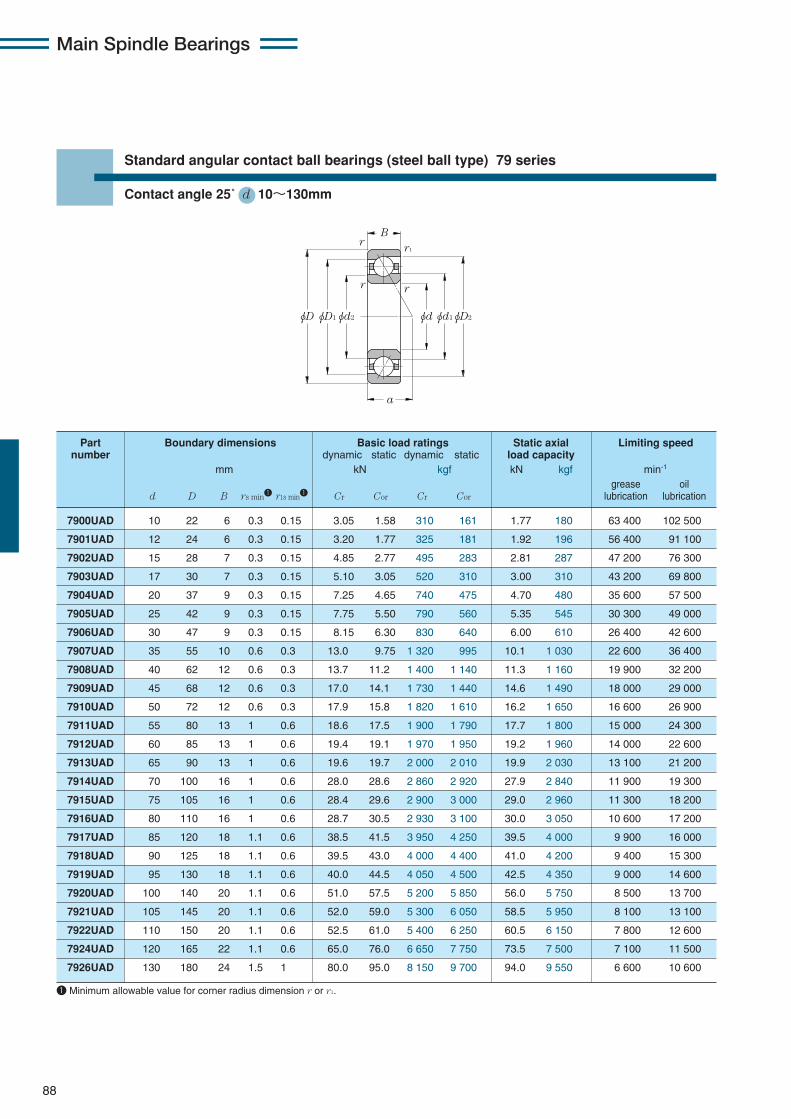
Main Spindle Bearings
88
Standard angular contact ball bearings (steel ball type) 79 series
Contact angle 25˚ d 10〜130mm
φDφD1 φD2φd2 φdφd1
B
a
r1
rr
r
7900UAD 10 22 6 0.3 0.15 3.05 1.58 310 161 1.77 180 63 400 102 500
7901UAD 12 24 6 0.3 0.15 3.20 1.77 325 181 1.92 196 56 400 91 100
7902UAD 15 28 7 0.3 0.15 4.85 2.77 495 283 2.81 287 47 200 76 300
7903UAD 17 30 7 0.3 0.15 5.10 3.05 520 310 3.00 310 43 200 69 800
7904UAD 20 37 9 0.3 0.15 7.25 4.65 740 475 4.70 480 35 600 57 500
7905UAD 25 42 9 0.3 0.15 7.75 5.50 790 560 5.35 545 30 300 49 000
7906UAD 30 47 9 0.3 0.15 8.15 6.30 830 640 6.00 610 26 400 42 600
7907UAD 35 55 10 0.6 0.3 13.0 9.75 1 320 995 10.1 1 030 22 600 36 400
7908UAD 40 62 12 0.6 0.3 13.7 11.2 1 400 1 140 11.3 1 160 19 900 32 200
7909UAD 45 68 12 0.6 0.3 17.0 14.1 1 730 1 440 14.6 1 490 18 000 29 000
7910UAD 50 72 12 0.6 0.3 17.9 15.8 1 820 1 610 16.2 1 650 16 600 26 900
7911UAD 55 80 13 1 0.6 18.6 17.5 1 900 1 790 17.7 1 800 15 000 24 300
7912UAD 60 85 13 1 0.6 19.4 19.1 1 970 1 950 19.2 1 960 14 000 22 600
7913UAD 65 90 13 1 0.6 19.6 19.7 2 000 2 010 19.9 2 030 13 100 21 200
7914UAD 70 100 16 1 0.6 28.0 28.6 2 860 2 920 27.9 2 840 11 900 19 300
7915UAD 75 105 16 1 0.6 28.4 29.6 2 900 3 000 29.0 2 960 11 300 18 200
7916UAD 80 110 16 1 0.6 28.7 30.5 2 930 3 100 30.0 3 050 10 600 17 200
7917UAD 85 120 18 1.1 0.6 38.5 41.5 3 950 4 250 39.5 4 000 9 900 16 000
7918UAD 90 125 18 1.1 0.6 39.5 43.0 4 000 4 400 41.0 4 200 9 400 15 300
7919UAD 95 130 18 1.1 0.6 40.0 44.5 4 050 4 500 42.5 4 350 9 000 14 600
7920UAD 100 140 20 1.1 0.6 51.0 57.5 5 200 5 850 56.0 5 750 8 500 13 700
7921UAD 105 145 20 1.1 0.6 52.0 59.0 5 300 6 050 58.5 5 950 8 100 13 100
7922UAD 110 150 20 1.1 0.6 52.5 61.0 5 400 6 250 60.5 6 150 7 800 12 600
7924UAD 120 165 22 1.1 0.6 65.0 76.0 6 650 7 750 73.5 7 500 7 100 11 500
7926UAD 130 180 24 1.5 1 80.0 95.0 8 150 9 700 94.0 9 550 6 600 10 600
Part Boundary dimensions Basic load ratings Static axial Limiting speednumber dynamic static dynamic static load capacity
mm kN kgf kN kgf min-1
grease oild D B rs min1 r1s min1 Cr Cor Cr Cor lubrication lubrication
1 Minimum allowable value for corner radius dimension r or r1.
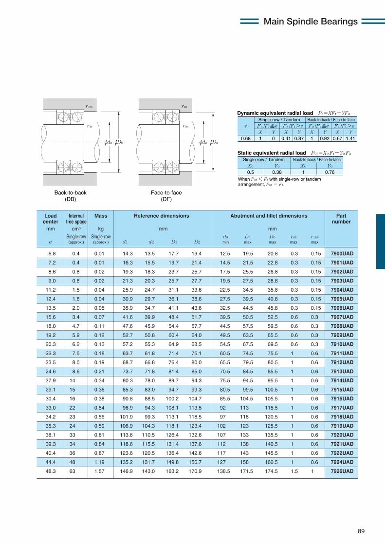
Main Spindle Bearings
89
X Y X Y X Y X Y0.68 1 0 0.41 0.87 1 0.92 0.67 1.41
Fa /Fr≦e Fa /Fr>e Fa /Fr≦e Fa /Fr>ee
Static equivalent radial load Por=Xo Fr+Yo Fa
When Por < Fr with single-row or tandem arrangement, Por = Fr.
Xo Yo Xo Yo
0.5 0.38 1 0.76
Dynamic equivalent radial load Pr=XFr+YFa
Single row / Tandem Back-to-back / Face-to-face
Single row / Tandem Back-to-back / Face-to-face
6.8 0.4 0.01 14.3 13.5 17.7 19.4 12.5 19.5 20.8 0.3 0.15 7900UAD
7.2 0.4 0.01 16.3 15.5 19.7 21.4 14.5 21.5 22.8 0.3 0.15 7901UAD
8.6 0.8 0.02 19.3 18.3 23.7 25.7 17.5 25.5 26.8 0.3 0.15 7902UAD
9.0 0.8 0.02 21.3 20.3 25.7 27.7 19.5 27.5 28.8 0.3 0.15 7903UAD
11.2 1.5 0.04 25.9 24.7 31.1 33.6 22.5 34.5 35.8 0.3 0.15 7904UAD
12.4 1.8 0.04 30.9 29.7 36.1 38.6 27.5 39.5 40.8 0.3 0.15 7905UAD
13.5 2.0 0.05 35.9 34.7 41.1 43.6 32.5 44.5 45.8 0.3 0.15 7906UAD
15.6 3.4 0.07 41.6 39.9 48.4 51.7 39.5 50.5 52.5 0.6 0.3 7907UAD
18.0 4.7 0.11 47.6 45.9 54.4 57.7 44.5 57.5 59.5 0.6 0.3 7908UAD
19.2 5.9 0.12 52.7 50.8 60.4 64.0 49.5 63.5 65.5 0.6 0.3 7909UAD
20.3 6.2 0.13 57.2 55.3 64.9 68.5 54.5 67.5 69.5 0.6 0.3 7910UAD
22.3 7.5 0.18 63.7 61.8 71.4 75.1 60.5 74.5 75.5 1 0.6 7911UAD
23.5 8.0 0.19 68.7 66.8 76.4 80.0 65.5 79.5 80.5 1 0.6 7912UAD
24.6 8.6 0.21 73.7 71.8 81.4 85.0 70.5 84.5 85.5 1 0.6 7913UAD
27.9 14 0.34 80.3 78.0 89.7 94.3 75.5 94.5 95.5 1 0.6 7914UAD
29.1 15 0.36 85.3 83.0 94.7 99.3 80.5 99.5 100.5 1 0.6 7915UAD
30.4 16 0.38 90.8 88.5 100.2 104.7 85.5 104.5 105.5 1 0.6 7916UAD
33.0 22 0.54 96.9 94.3 108.1 113.5 92 113 115.5 1 0.6 7917UAD
34.2 23 0.56 101.9 99.3 113.1 118.5 97 118 120.5 1 0.6 7918UAD
35.3 24 0.59 106.9 104.3 118.1 123.4 102 123 125.5 1 0.6 7919UAD
38.1 33 0.81 113.6 110.5 126.4 132.6 107 133 135.5 1 0.6 7920UAD
39.3 34 0.84 118.6 115.5 131.4 137.6 112 138 140.5 1 0.6 7921UAD
40.4 36 0.87 123.6 120.5 136.4 142.6 117 143 145.5 1 0.6 7922UAD
44.4 48 1.19 135.2 131.7 149.8 156.7 127 158 160.5 1 0.6 7924UAD
48.3 63 1.57 146.9 143.0 163.2 170.9 138.5 171.5 174.5 1.5 1 7926UAD
Load Internal Mass Reference dimensions Abutment and fillet dimensions Part center free space numbermm cm3 kg mm mm
Single-row Single-row da Da Db ras r1asa (approx.) (approx.) d1 d2 D1 D2 min max max max max
φDbφda
ras
r1as
φDaφda
ras
ras
Back-to-back (DB)
Face-to-face (DF)
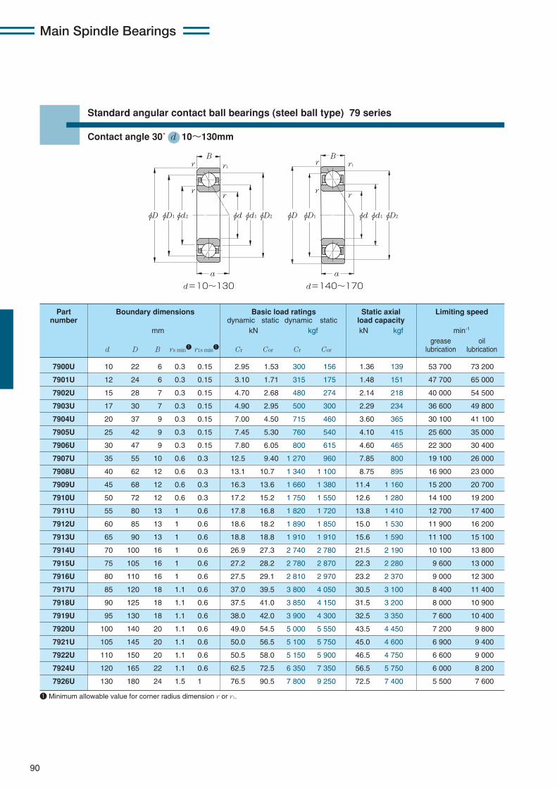
7900U 10 22 6 0.3 0.15 2.95 1.53 300 156 1.36 139 53 700 73 200
7901U 12 24 6 0.3 0.15 3.10 1.71 315 175 1.48 151 47 700 65 000
7902U 15 28 7 0.3 0.15 4.70 2.68 480 274 2.14 218 40 000 54 500
7903U 17 30 7 0.3 0.15 4.90 2.95 500 300 2.29 234 36 600 49 800
7904U 20 37 9 0.3 0.15 7.00 4.50 715 460 3.60 365 30 100 41 100
7905U 25 42 9 0.3 0.15 7.45 5.30 760 540 4.10 415 25 600 35 000
7906U 30 47 9 0.3 0.15 7.80 6.05 800 615 4.60 465 22 300 30 400
7907U 35 55 10 0.6 0.3 12.5 9.40 1 270 960 7.85 800 19 100 26 000
7908U 40 62 12 0.6 0.3 13.1 10.7 1 340 1 100 8.75 895 16 900 23 000
7909U 45 68 12 0.6 0.3 16.3 13.6 1 660 1 380 11.4 1 160 15 200 20 700
7910U 50 72 12 0.6 0.3 17.2 15.2 1 750 1 550 12.6 1 280 14 100 19 200
7911U 55 80 13 1 0.6 17.8 16.8 1 820 1 720 13.8 1 410 12 700 17 400
7912U 60 85 13 1 0.6 18.6 18.2 1 890 1 850 15.0 1 530 11 900 16 200
7913U 65 90 13 1 0.6 18.8 18.8 1 910 1 910 15.6 1 590 11 100 15 100
7914U 70 100 16 1 0.6 26.9 27.3 2 740 2 780 21.5 2 190 10 100 13 800
7915U 75 105 16 1 0.6 27.2 28.2 2 780 2 870 22.3 2 280 9 600 13 000
7916U 80 110 16 1 0.6 27.5 29.1 2 810 2 970 23.2 2 370 9 000 12 300
7917U 85 120 18 1.1 0.6 37.0 39.5 3 800 4 050 30.5 3 100 8 400 11 400
7918U 90 125 18 1.1 0.6 37.5 41.0 3 850 4 150 31.5 3 200 8 000 10 900
7919U 95 130 18 1.1 0.6 38.0 42.0 3 900 4 300 32.5 3 350 7 600 10 400
7920U 100 140 20 1.1 0.6 49.0 54.5 5 000 5 550 43.5 4 450 7 200 9 800
7921U 105 145 20 1.1 0.6 50.0 56.5 5 100 5 750 45.0 4 600 6 900 9 400
7922U 110 150 20 1.1 0.6 50.5 58.0 5 150 5 900 46.5 4 750 6 600 9 000
7924U 120 165 22 1.1 0.6 62.5 72.5 6 350 7 350 56.5 5 750 6 000 8 200
7926U 130 180 24 1.5 1 76.5 90.5 7 800 9 250 72.5 7 400 5 500 7 600
Main Spindle Bearings
90
Standard angular contact ball bearings (steel ball type) 79 series
Contact angle 30˚ d 10〜130mm
φD φD1 φD2φd2 φdφd1
B
a
d=10~130 d=140~170
φD φD1 φD2φdφd1
B
a
r1r
rr
r
rr
r1
Part Boundary dimensions Basic load ratings Static axial Limiting speednumber dynamic static dynamic static load capacity
mm kN kgf kN kgf min-1
grease oild D B rs min1 r1s min1 Cr Cor Cr Cor lubrication lubrication
1 Minimum allowable value for corner radius dimension r or r1.

Load Internal Mass Reference dimensions Abutment and fillet dimensions Part center free space numbermm cm3 kg mm mm
Single-row Single-row da Da Db ras r1asa (approx.) (approx.) d1 d2 D1 D2 min max max max max
7.7 0.4 0.01 14.3 13.5 17.7 19.3 12.5 19.5 20.8 0.3 0.15 7900U
8.2 0.4 0.01 16.3 15.5 19.7 21.3 14.5 21.5 22.8 0.3 0.15 7901U
9.8 0.8 0.02 19.3 18.3 23.7 25.7 17.5 25.5 26.8 0.3 0.15 7902U
10.3 0.8 0.02 21.3 20.3 25.7 27.7 19.5 27.5 28.8 0.3 0.15 7903U
12.8 1.5 0.04 25.9 24.7 31.1 33.5 22.5 34.5 35.8 0.3 0.15 7904U
14.2 1.8 0.04 30.9 29.7 36.1 38.5 27.5 39.5 40.8 0.3 0.15 7905U
15.7 2.0 0.05 35.9 34.7 41.1 43.5 32.5 44.5 45.8 0.3 0.15 7906U
18.1 3.4 0.07 41.6 39.9 48.4 51.6 39.5 50.5 52.5 0.6 0.3 7907U
20.8 4.7 0.11 47.6 45.9 54.4 57.7 44.5 57.5 59.5 0.6 0.3 7908U
22.4 5.9 0.12 52.7 50.8 60.4 64.0 49.5 63.5 65.5 0.6 0.3 7909U
23.7 6.2 0.13 57.2 55.3 64.9 68.4 54.5 67.5 69.5 0.6 0.3 7910U
26.1 7.5 0.18 63.7 61.8 71.4 75.0 60.5 74.5 75.5 1 0.6 7911U
27.5 8.0 0.19 68.7 66.8 76.4 80.0 65.5 79.5 80.5 1 0.6 7912U
29.0 8.6 0.21 73.7 71.8 81.4 85.0 70.5 84.5 85.5 1 0.6 7913U
32.6 14 0.34 80.3 78.0 89.7 94.2 75.5 94.5 95.5 1 0.6 7914U
34.1 15 0.36 85.3 83.0 94.7 99.2 80.5 99.5 100.5 1 0.6 7915U
35.7 16 0.38 90.8 88.5 100.2 104.7 85.5 104.5 105.5 1 0.6 7916U
38.7 22 0.54 96.9 94.3 108.1 113.4 92 113 115.5 1 0.6 7917U
40.2 23 0.56 101.9 99.3 113.1 118.4 97 118 120.5 1 0.6 7918U
41.6 24 0.59 106.9 104.3 118.1 123.4 102 123 125.5 1 0.6 7919U
44.8 33 0.81 113.6 110.5 126.4 132.6 107 133 135.5 1 0.6 7920U
46.2 34 0.84 118.6 115.5 131.4 137.6 112 138 140.5 1 0.6 7921U
47.7 36 0.87 123.6 120.5 136.4 142.6 117 143 145.5 1 0.6 7922U
52.3 48 1.19 135.2 131.7 149.8 156.7 127 158 160.5 1 0.6 7924U
56.9 63 1.57 146.9 143.0 163.2 170.9 138.5 171.5 174.5 1.5 1 7926U
Main Spindle Bearings
91
X Y X Y X Y X Y0.8 1 0 0.39 0.76 1 0.78 0.63 1.24
Fa /Fr≦e Fa /Fr>e Fa /Fr≦e Fa /Fr>eSingle row / Tandem Back-to-back / Face-to-face
e
Static equivalent radial load Por=Xo Fr+Yo Fa
When Por < Fr with single-row or tandem arrangement, Por = Fr.
Xo Yo Xo Yo
0.5 0.33 1 0.66
Single row / Tandem Back-to-back / Face-to-face
Dynamic equivalent radial load Pr=XFr+YFa
φDbφda
ras
r1as
φDaφda
ras
ras
Back-to-back (DB)
Face-to-face (DF)
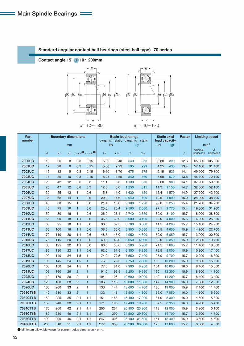
Main Spindle Bearings
92
Standard angular contact ball bearings (steel ball type) 70 series
Contact angle 15˚ d 10〜200mm
7000UC 10 26 8 0.3 0.15 5.30 2.48 540 253 3.80 390 12.6 65 800 105 300
7001UC 12 28 8 0.3 0.15 5.80 2.93 595 299 4.25 435 13.4 57 100 91 400
7002UC 15 32 9 0.3 0.15 6.60 3.70 675 375 5.15 525 14.1 49 900 79 800
7003UC 17 35 10 0.3 0.15 8.25 4.55 840 460 6.60 670 13.8 45 100 72 100
7004UC 20 42 12 0.6 0.3 11.1 6.6 1 130 670 9.60 980 14.1 37 200 59 500
7005UC 25 47 12 0.6 0.3 12.3 8.0 1 250 815 11.3 1 150 14.7 32 500 52 100
7006UC 30 55 13 1 0.6 15.8 11.0 1 620 1 120 15.4 1 570 14.9 27 200 43 600
7007UC 35 62 14 1 0.6 20.0 14.6 2 040 1 490 19.5 1 990 15.0 24 200 38 700
7008UC 40 68 15 1 0.6 21.4 16.8 2 180 1 720 22.0 2 250 15.4 21 700 34 700
7009UC 45 75 16 1 0.6 25.3 20.4 2 580 2 080 27.1 2 770 15.4 19 500 31 200
7010UC 50 80 16 1 0.6 26.9 23.1 2 740 2 350 30.0 3 100 15.7 18 000 28 800
7011UC 55 90 18 1.1 0.6 35.5 30.0 3 600 3 100 39.0 4 000 15.5 16 200 25 900
7012UC 60 95 18 1.1 0.6 36.5 32.5 3 700 3 300 41.5 4 200 15.7 15 100 24 200
7013UC 65 100 18 1.1 0.6 38.5 36.0 3 900 3 650 45.5 4 650 15.9 14 200 22 700
7014UC 70 110 20 1.1 0.6 48.5 45.0 4 950 4 600 59.0 6 050 15.7 13 000 20 800
7015UC 75 115 20 1.1 0.6 49.5 48.0 5 050 4 900 62.0 6 350 15.9 12 300 19 700
7016UC 80 125 22 1.1 0.6 60.5 58.0 6 200 5 900 74.5 7 600 15.7 11 400 18 300
7017UC 85 130 22 1.1 0.6 62.0 61.5 6 350 6 250 78.5 8 000 15.9 10 900 17 400
7018UC 90 140 24 1.5 1 74.0 72.5 7 550 7 400 95.0 9 700 15.7 10 200 16 300
7019UC 95 145 24 1.5 1 76.0 76.5 7 750 7 800 100 10 200 15.9 9 800 15 600
7020UC 100 150 24 1.5 1 77.5 81.0 7 900 8 250 104 10 600 16.0 9 400 15 000
7021UC 105 160 26 2 1 91.0 93.5 9 250 9 550 120 12 300 15.9 8 800 14 100
7022UC 110 170 28 2 1 104 106 10 600 10 900 140 14 200 15.7 8 400 13 400
7024UC 120 180 28 2 1 106 113 10 800 11 500 147 14 900 16.0 7 800 12 500
7026UC 130 200 33 2 1 133 144 13 600 14 700 186 19 000 15.9 7 100 11 400
7028CT1B 140 210 33 2 1 132 145 13 500 14 800 69.0 7 050 16.0 4 800 6 200
7030CT1B 150 225 35 2.1 1.1 151 168 15 400 17 200 81.0 8 300 16.0 4 500 5 800
7032CT1B 160 240 38 2.1 1.1 171 193 17 400 19 700 87.5 8 950 16.0 4 200 5 400
7034CT1B 170 260 42 2.1 1.1 205 234 20 900 23 900 118 12 000 15.9 3 900 5 100
7036CT1B 180 280 46 2.1 1.1 241 290 24 500 29 600 144 14 700 15.7 3 700 4 700
7038CT1B 190 290 46 2.1 1.1 247 305 25 100 31 500 151 15 400 15.9 3 500 4 500
7040CT1B 200 310 51 2.1 1.1 277 355 28 200 36 000 173 17 600 15.7 3 300 4 300
Part Boundary dimensions Basic load ratings Static axial Factor Limiting speednumber dynamic static dynamic static load capacity
mm kN kgf kN kgf min-1
grease oild D B rs min1 r1s min1 Cr Cor Cr Cor fo lubrication lubrication
φD φD1 φD2φd2 φdφd1
B
a
d=10~130 d=140~170
φD φD1 φD2φdφd1
B
a
r1r
rr
r
rr
r1
1 Minimum allowable value for corner radius dimension r or r1.
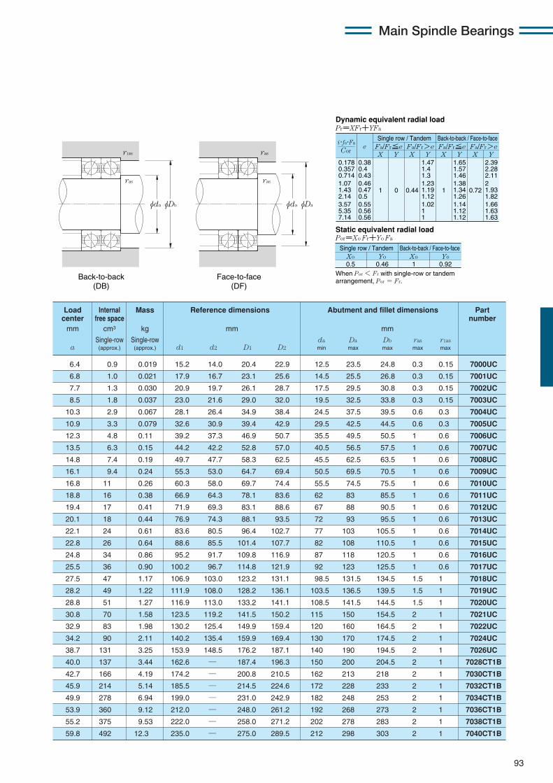
Main Spindle Bearings
93
0.178 0.357 0.714 1.07 1.43 2.14 3.57 5.35 7.14
eX Y
Dynamic equivalent radial loadPr=XFr+YFa
Static equivalent radial loadPor=Xo Fr+Yo Fa
Fa/Fr≦e Fa/Fr>eSingle row / Tandem Back-to-back / Face-to-face
Fa/Fr≦e Fa/Fr>eX Y X Y X Y
0.38 0.4 0.43 0.46 0.47 0.5 0.55 0.56 0.56
1 0 0.44
1.47 1.4 1.3 1.23 1.19 1.12 1.02 1 1
1
1.65 1.57 1.46 1.38 1.34 1.26 1.14 1.12 1.12
0.72
2.39 2.28 2.11 2 1.93 1.82 1.66 1.63 1.63
Xo
Single row / Tandem Back-to-back / Face-to-face
0.5Yo Xo Yo
0.46 1 0.92
Cor
i・fo・Fa
When Por < Fr with single-row or tandem arrangement, Por = Fr.
Load Internal Mass Reference dimensions Abutment and fillet dimensions Part center free space numbermm cm3 kg mm mm
Single-row Single-row da Da Db ras r1asa (approx.) (approx.) d1 d2 D1 D2 min max max max max
φDbφda
ras
r1as
φDaφda
ras
ras
Back-to-back (DB)
Face-to-face (DF)
6.4 0.9 0.019 15.2 14.0 20.4 22.9 12.5 23.5 24.8 0.3 0.15 7000UC
6.8 1.0 0.021 17.9 16.7 23.1 25.6 14.5 25.5 26.8 0.3 0.15 7001UC
7.7 1.3 0.030 20.9 19.7 26.1 28.7 17.5 29.5 30.8 0.3 0.15 7002UC
8.5 1.8 0.037 23.0 21.6 29.0 32.0 19.5 32.5 33.8 0.3 0.15 7003UC
10.3 2.9 0.067 28.1 26.4 34.9 38.4 24.5 37.5 39.5 0.6 0.3 7004UC
10.9 3.3 0.079 32.6 30.9 39.4 42.9 29.5 42.5 44.5 0.6 0.3 7005UC
12.3 4.8 0.11 39.2 37.3 46.9 50.7 35.5 49.5 50.5 1 0.6 7006UC
13.5 6.3 0.15 44.2 42.2 52.8 57.0 40.5 56.5 57.5 1 0.6 7007UC
14.8 7.4 0.19 49.7 47.7 58.3 62.5 45.5 62.5 63.5 1 0.6 7008UC
16.1 9.4 0.24 55.3 53.0 64.7 69.4 50.5 69.5 70.5 1 0.6 7009UC
16.8 11 0.26 60.3 58.0 69.7 74.4 55.5 74.5 75.5 1 0.6 7010UC
18.8 16 0.38 66.9 64.3 78.1 83.6 62 83 85.5 1 0.6 7011UC
19.4 17 0.41 71.9 69.3 83.1 88.6 67 88 90.5 1 0.6 7012UC
20.1 18 0.44 76.9 74.3 88.1 93.5 72 93 95.5 1 0.6 7013UC
22.1 24 0.61 83.6 80.5 96.4 102.7 77 103 105.5 1 0.6 7014UC
22.8 26 0.64 88.6 85.5 101.4 107.7 82 108 110.5 1 0.6 7015UC
24.8 34 0.86 95.2 91.7 109.8 116.9 87 118 120.5 1 0.6 7016UC
25.5 36 0.90 100.2 96.7 114.8 121.9 92 123 125.5 1 0.6 7017UC
27.5 47 1.17 106.9 103.0 123.2 131.1 98.5 131.5 134.5 1.5 1 7018UC
28.2 49 1.22 111.9 108.0 128.2 136.1 103.5 136.5 139.5 1.5 1 7019UC
28.8 51 1.27 116.9 113.0 133.2 141.1 108.5 141.5 144.5 1.5 1 7020UC
30.8 70 1.58 123.5 119.2 141.5 150.2 115 150 154.5 2 1 7021UC
32.9 83 1.98 130.2 125.4 149.9 159.4 120 160 164.5 2 1 7022UC
34.2 90 2.11 140.2 135.4 159.9 169.4 130 170 174.5 2 1 7024UC
38.7 131 3.25 153.9 148.5 176.2 187.1 140 190 194.5 2 1 7026UC
40.0 137 3.44 162.6 — 187.4 196.3 150 200 204.5 2 1 7028CT1B
42.7 166 4.19 174.2 — 200.8 210.5 162 213 218 2 1 7030CT1B
45.9 214 5.14 185.5 — 214.5 224.6 172 228 233 2 1 7032CT1B
49.9 278 6.94 199.0 — 231.0 242.9 182 248 253 2 1 7034CT1B
53.9 360 9.12 212.0 — 248.0 261.2 192 268 273 2 1 7036CT1B
55.2 375 9.53 222.0 — 258.0 271.2 202 278 283 2 1 7038CT1B
59.8 492 12.3 235.0 — 275.0 289.5 212 298 303 2 1 7040CT1B
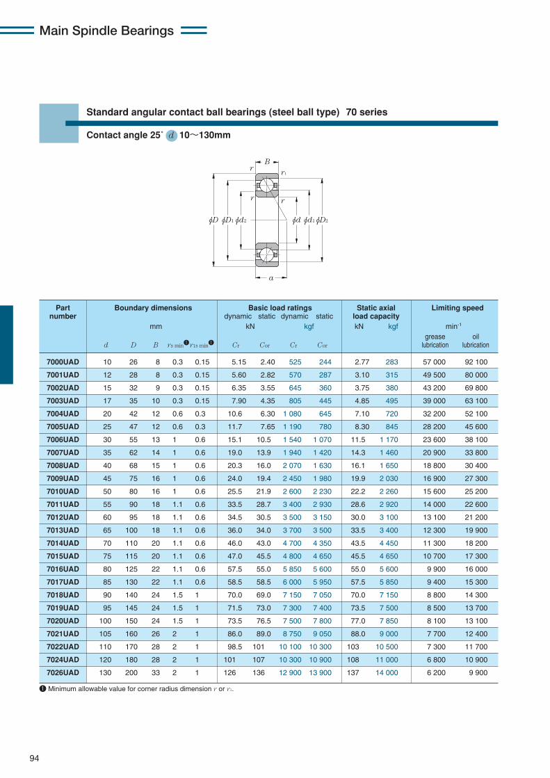
Main Spindle Bearings
94
Standard angular contact ball bearings (steel ball type) 70 series
Contact angle 25˚ d 10〜130mm
7000UAD 10 26 8 0.3 0.15 5.15 2.40 525 244 2.77 283 57 000 92 100
7001UAD 12 28 8 0.3 0.15 5.60 2.82 570 287 3.10 315 49 500 80 000
7002UAD 15 32 9 0.3 0.15 6.35 3.55 645 360 3.75 380 43 200 69 800
7003UAD 17 35 10 0.3 0.15 7.90 4.35 805 445 4.85 495 39 000 63 100
7004UAD 20 42 12 0.6 0.3 10.6 6.30 1 080 645 7.10 720 32 200 52 100
7005UAD 25 47 12 0.6 0.3 11.7 7.65 1 190 780 8.30 845 28 200 45 600
7006UAD 30 55 13 1 0.6 15.1 10.5 1 540 1 070 11.5 1 170 23 600 38 100
7007UAD 35 62 14 1 0.6 19.0 13.9 1 940 1 420 14.3 1 460 20 900 33 800
7008UAD 40 68 15 1 0.6 20.3 16.0 2 070 1 630 16.1 1 650 18 800 30 400
7009UAD 45 75 16 1 0.6 24.0 19.4 2 450 1 980 19.9 2 030 16 900 27 300
7010UAD 50 80 16 1 0.6 25.5 21.9 2 600 2 230 22.2 2 260 15 600 25 200
7011UAD 55 90 18 1.1 0.6 33.5 28.7 3 400 2 930 28.6 2 920 14 000 22 600
7012UAD 60 95 18 1.1 0.6 34.5 30.5 3 500 3 150 30.0 3 100 13 100 21 200
7013UAD 65 100 18 1.1 0.6 36.0 34.0 3 700 3 500 33.5 3 400 12 300 19 900
7014UAD 70 110 20 1.1 0.6 46.0 43.0 4 700 4 350 43.5 4 450 11 300 18 200
7015UAD 75 115 20 1.1 0.6 47.0 45.5 4 800 4 650 45.5 4 650 10 700 17 300
7016UAD 80 125 22 1.1 0.6 57.5 55.0 5 850 5 600 55.0 5 600 9 900 16 000
7017UAD 85 130 22 1.1 0.6 58.5 58.5 6 000 5 950 57.5 5 850 9 400 15 300
7018UAD 90 140 24 1.5 1 70.0 69.0 7 150 7 050 70.0 7 150 8 800 14 300
7019UAD 95 145 24 1.5 1 71.5 73.0 7 300 7 400 73.5 7 500 8 500 13 700
7020UAD 100 150 24 1.5 1 73.5 76.5 7 500 7 800 77.0 7 850 8 100 13 100
7021UAD 105 160 26 2 1 86.0 89.0 8 750 9 050 88.0 9 000 7 700 12 400
7022UAD 110 170 28 2 1 98.5 101 10 100 10 300 103 10 500 7 300 11 700
7024UAD 120 180 28 2 1 101 107 10 300 10 900 108 11 000 6 800 10 900
7026UAD 130 200 33 2 1 126 136 12 900 13 900 137 14 000 6 200 9 900
Part Boundary dimensions Basic load ratings Static axial Limiting speednumber dynamic static dynamic static load capacity
mm kN kgf kN kgf min-1
grease oild D B rs min1r1s min1 Cr Cor Cr Cor lubrication lubrication
φDφD1 φD2φd2 φdφd1
B
a
r1
rr
r
1 Minimum allowable value for corner radius dimension r or r1.
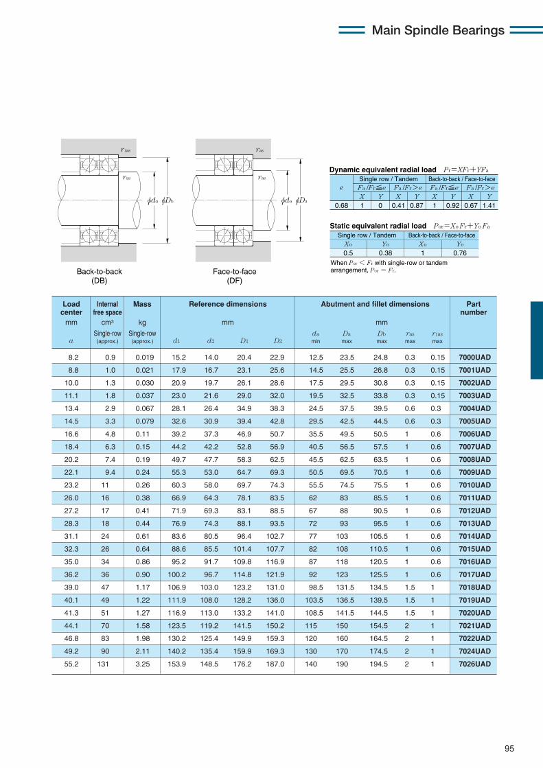
Main Spindle Bearings
95
Load Internal Mass Reference dimensions Abutment and fillet dimensions Partcenter free space numbermm cm3 kg mm mm
Single-row Single-row da Da Db ras r1asa (approx.) (approx.) d1 d2 D1 D2 min max max max max
X Y X Y X Y X Y0.68 1 0 0.41 0.87 1 0.92 0.67 1.41
Fa /Fr≦e Fa /Fr>e Fa /Fr≦e Fa /Fr>ee
Static equivalent radial load Por=Xo Fr+Yo Fa
When Por < Fr with single-row or tandem arrangement, Por = Fr.
Xo Yo Xo Yo
0.5 0.38 1 0.76
Dynamic equivalent radial load Pr=XFr+YFa
Single row / Tandem Back-to-back / Face-to-face
Single row / Tandem Back-to-back / Face-to-face
φDbφda
ras
r1as
φDaφda
ras
ras
Back-to-back (DB)
Face-to-face (DF)
8.2 0.9 0.019 15.2 14.0 20.4 22.9 12.5 23.5 24.8 0.3 0.15 7000UAD
8.8 1.0 0.021 17.9 16.7 23.1 25.6 14.5 25.5 26.8 0.3 0.15 7001UAD
10.0 1.3 0.030 20.9 19.7 26.1 28.6 17.5 29.5 30.8 0.3 0.15 7002UAD
11.1 1.8 0.037 23.0 21.6 29.0 32.0 19.5 32.5 33.8 0.3 0.15 7003UAD
13.4 2.9 0.067 28.1 26.4 34.9 38.3 24.5 37.5 39.5 0.6 0.3 7004UAD
14.5 3.3 0.079 32.6 30.9 39.4 42.8 29.5 42.5 44.5 0.6 0.3 7005UAD
16.6 4.8 0.11 39.2 37.3 46.9 50.7 35.5 49.5 50.5 1 0.6 7006UAD
18.4 6.3 0.15 44.2 42.2 52.8 56.9 40.5 56.5 57.5 1 0.6 7007UAD
20.2 7.4 0.19 49.7 47.7 58.3 62.5 45.5 62.5 63.5 1 0.6 7008UAD
22.1 9.4 0.24 55.3 53.0 64.7 69.3 50.5 69.5 70.5 1 0.6 7009UAD
23.2 11 0.26 60.3 58.0 69.7 74.3 55.5 74.5 75.5 1 0.6 7010UAD
26.0 16 0.38 66.9 64.3 78.1 83.5 62 83 85.5 1 0.6 7011UAD
27.2 17 0.41 71.9 69.3 83.1 88.5 67 88 90.5 1 0.6 7012UAD
28.3 18 0.44 76.9 74.3 88.1 93.5 72 93 95.5 1 0.6 7013UAD
31.1 24 0.61 83.6 80.5 96.4 102.7 77 103 105.5 1 0.6 7014UAD
32.3 26 0.64 88.6 85.5 101.4 107.7 82 108 110.5 1 0.6 7015UAD
35.0 34 0.86 95.2 91.7 109.8 116.9 87 118 120.5 1 0.6 7016UAD
36.2 36 0.90 100.2 96.7 114.8 121.9 92 123 125.5 1 0.6 7017UAD
39.0 47 1.17 106.9 103.0 123.2 131.0 98.5 131.5 134.5 1.5 1 7018UAD
40.1 49 1.22 111.9 108.0 128.2 136.0 103.5 136.5 139.5 1.5 1 7019UAD
41.3 51 1.27 116.9 113.0 133.2 141.0 108.5 141.5 144.5 1.5 1 7020UAD
44.1 70 1.58 123.5 119.2 141.5 150.2 115 150 154.5 2 1 7021UAD
46.8 83 1.98 130.2 125.4 149.9 159.3 120 160 164.5 2 1 7022UAD
49.2 90 2.11 140.2 135.4 159.9 169.3 130 170 174.5 2 1 7024UAD
55.2 131 3.25 153.9 148.5 176.2 187.0 140 190 194.5 2 1 7026UAD
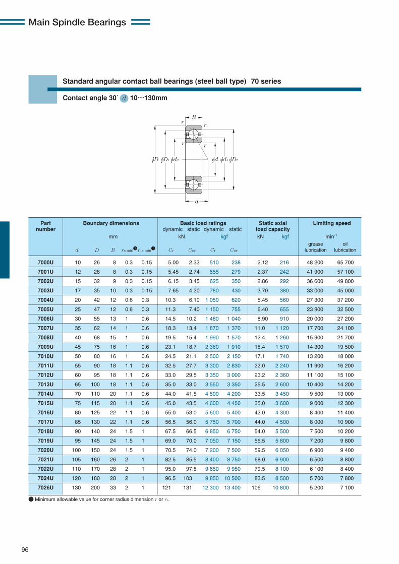
Main Spindle Bearings
96
Standard angular contact ball bearings (steel ball type) 70 series
Contact angle 30˚ d 10〜130mm
7000U 10 26 8 0.3 0.15 5.00 2.33 510 238 2.12 216 48 200 65 700
7001U 12 28 8 0.3 0.15 5.45 2.74 555 279 2.37 242 41 900 57 100
7002U 15 32 9 0.3 0.15 6.15 3.45 625 350 2.86 292 36 600 49 800
7003U 17 35 10 0.3 0.15 7.65 4.20 780 430 3.70 380 33 000 45 000
7004U 20 42 12 0.6 0.3 10.3 6.10 1 050 620 5.45 560 27 300 37 200
7005U 25 47 12 0.6 0.3 11.3 7.40 1 150 755 6.40 655 23 900 32 500
7006U 30 55 13 1 0.6 14.5 10.2 1 480 1 040 8.90 910 20 000 27 200
7007U 35 62 14 1 0.6 18.3 13.4 1 870 1 370 11.0 1 120 17 700 24 100
7008U 40 68 15 1 0.6 19.5 15.4 1 990 1 570 12.4 1 260 15 900 21 700
7009U 45 75 16 1 0.6 23.1 18.7 2 360 1 910 15.4 1 570 14 300 19 500
7010U 50 80 16 1 0.6 24.5 21.1 2 500 2 150 17.1 1 740 13 200 18 000
7011U 55 90 18 1.1 0.6 32.5 27.7 3 300 2 830 22.0 2 240 11 900 16 200
7012U 60 95 18 1.1 0.6 33.0 29.5 3 350 3 000 23.2 2 360 11 100 15 100
7013U 65 100 18 1.1 0.6 35.0 33.0 3 550 3 350 25.5 2 600 10 400 14 200
7014U 70 110 20 1.1 0.6 44.0 41.5 4 500 4 200 33.5 3 450 9 500 13 000
7015U 75 115 20 1.1 0.6 45.0 43.5 4 600 4 450 35.0 3 600 9 000 12 300
7016U 80 125 22 1.1 0.6 55.0 53.0 5 600 5 400 42.0 4 300 8 400 11 400
7017U 85 130 22 1.1 0.6 56.5 56.0 5 750 5 700 44.0 4 500 8 000 10 900
7018U 90 140 24 1.5 1 67.5 66.5 6 850 6 750 54.0 5 500 7 500 10 200
7019U 95 145 24 1.5 1 69.0 70.0 7 050 7 150 56.5 5 800 7 200 9 800
7020U 100 150 24 1.5 1 70.5 74.0 7 200 7 500 59.5 6 050 6 900 9 400
7021U 105 160 26 2 1 82.5 85.5 8 400 8 750 68.0 6 900 6 500 8 800
7022U 110 170 28 2 1 95.0 97.5 9 650 9 950 79.5 8 100 6 100 8 400
7024U 120 180 28 2 1 96.5 103 9 850 10 500 83.5 8 500 5 700 7 800
7026U 130 200 33 2 1 121 131 12 300 13 400 106 10 800 5 200 7 100
Part Boundary dimensions Basic load ratings Static axial Limiting speednumber dynamic static dynamic static load capacity
mm kN kgf kN kgf min-1
grease oild D B rs min1r1s min1 Cr Cor Cr Cor lubrication lubrication
φDφD1 φD2φd2 φdφd1
B
a
r1
rr
r
1 Minimum allowable value for corner radius dimension r or r1.

Main Spindle Bearings
97
Load Internal Mass Reference dimensions Abutment and fillet dimensions Partcenter free space numbermm cm3 kg mm mm
Single-row Single-row da Da Db ras r1asa (approx.) (approx.) d1 d2 D1 D2 min max max max max
X Y X Y X Y X Y0.8 1 0 0.39 0.76 1 0.78 0.63 1.24
Fa /Fr≦e Fa /Fr>e Fa /Fr≦e Fa /Fr>eSingle row / Tandem Back-to-back / Face-to-face
e
Static equivalent radial load Por=Xo Fr+Yo Fa
When Por < Fr with single-row or tandem arrangement, Por = Fr.
Xo Yo Xo Yo
0.5 0.33 1 0.66
Single row / Tandem Back-to-back / Face-to-face
Dynamic equivalent radial load Pr=XFr+YFa
φDbφda
ras
r1as
φDaφda
ras
ras
Back-to-back (DB)
Face-to-face (DF)
9.2 0.9 0.019 15.2 14.0 20.4 22.8 12.5 23.5 24.8 0.3 0.15 7000U
10.0 1.0 0.021 17.9 16.7 23.1 25.5 14.5 25.5 26.8 0.3 0.15 7001U
11.3 1.3 0.030 20.9 19.7 26.1 28.6 17.5 29.5 30.8 0.3 0.15 7002U
12.6 1.8 0.037 23.0 21.6 29.0 31.9 19.5 32.5 33.8 0.3 0.15 7003U
15.2 2.9 0.067 28.1 26.4 34.9 38.3 24.5 37.5 39.5 0.6 0.3 7004U
16.5 3.3 0.079 32.6 30.9 39.4 42.8 29.5 42.5 44.5 0.6 0.3 7005U
19.0 4.8 0.11 39.2 37.3 46.9 50.6 35.5 49.5 50.5 1 0.6 7006U
21.1 6.3 0.15 44.2 42.2 52.8 56.9 40.5 56.5 57.5 1 0.6 7007U
23.2 7.4 0.19 49.7 47.7 58.3 62.4 45.5 62.5 63.5 1 0.6 7008U
25.4 9.4 0.24 55.3 53.0 64.7 69.3 50.5 69.5 70.5 1 0.6 7009U
26.9 11 0.26 60.3 58.0 69.7 74.3 55.5 74.5 75.5 1 0.6 7010U
30.1 16 0.38 66.9 64.3 78.1 83.5 62 83 85.5 1 0.6 7011U
31.5 17 0.41 71.9 69.3 83.1 88.5 67 88 90.5 1 0.6 7012U
32.9 18 0.44 76.9 74.3 88.1 93.4 72 93 95.5 1 0.6 7013U
36.1 24 0.61 83.6 80.5 96.4 102.6 77 103 105.5 1 0.6 7014U
37.6 26 0.64 88.6 85.5 101.4 107.6 82 108 110.5 1 0.6 7015U
40.8 34 0.86 95.2 91.7 109.8 116.8 87 118 120.5 1 0.6 7016U
42.2 36 0.90 100.2 96.7 114.8 121.8 92 123 125.5 1 0.6 7017U
45.4 47 1.17 106.9 103.0 123.2 131.0 98.5 131.5 134.5 1.5 1 7018U
46.8 49 1.22 111.9 108.0 128.2 136.0 103.5 136.5 139.5 1.5 1 7019U
48.3 51 1.27 116.9 113.0 133.2 141.0 108.5 141.5 144.5 1.5 1 7020U
51.5 70 1.58 123.5 119.2 141.5 150.1 115 150 154.5 2 1 7021U
54.6 83 1.98 130.2 125.4 149.9 159.3 120 160 164.5 2 1 7022U
57.5 90 2.11 140.2 135.4 159.9 169.2 130 170 174.5 2 1 7024U
64.4 131 3.25 153.9 148.5 176.2 186.9 140 190 194.5 2 1 7026U
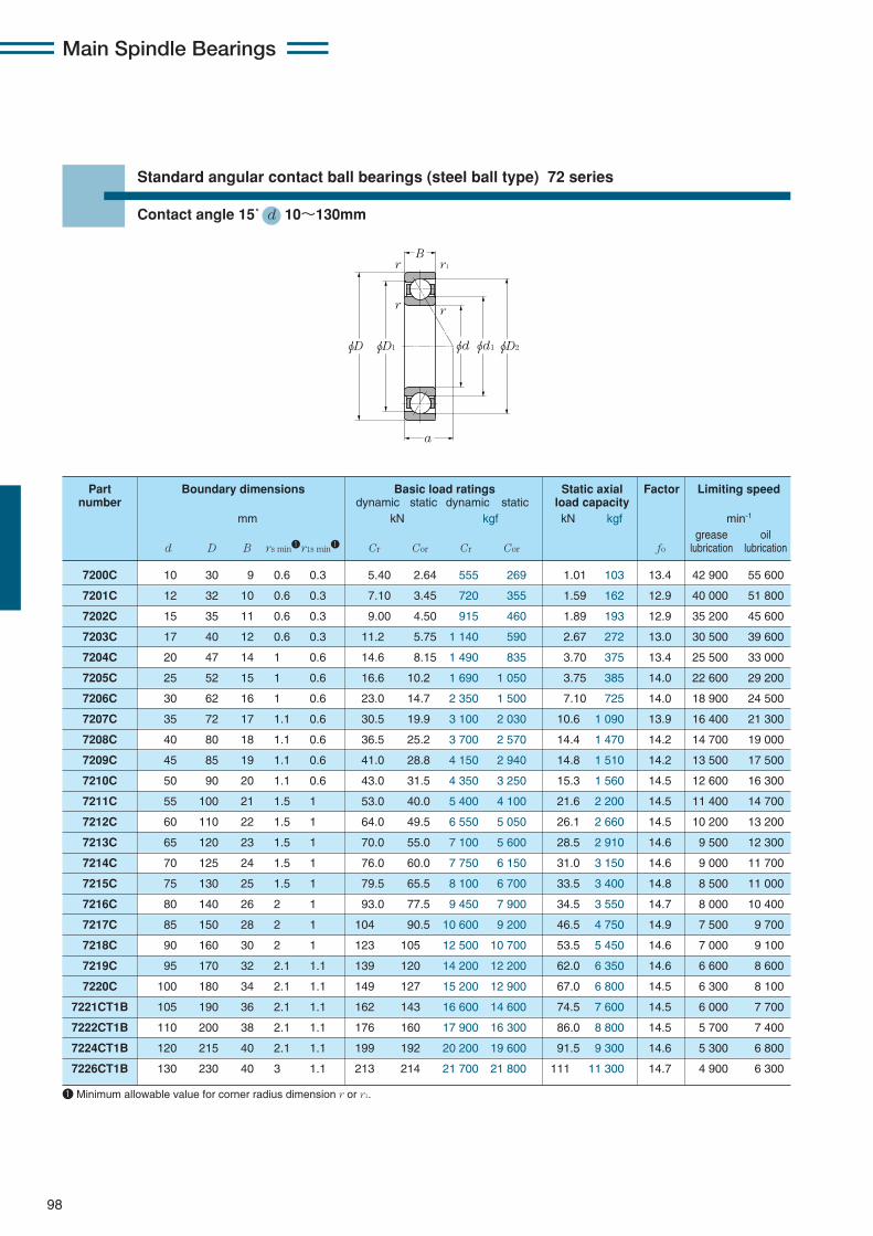
Main Spindle Bearings
98
Standard angular contact ball bearings (steel ball type) 72 series
Contact angle 15˚ d 10〜130mm
7200C 10 30 9 0.6 0.3 5.40 2.64 555 269 1.01 103 13.4 42 900 55 600
7201C 12 32 10 0.6 0.3 7.10 3.45 720 355 1.59 162 12.9 40 000 51 800
7202C 15 35 11 0.6 0.3 9.00 4.50 915 460 1.89 193 12.9 35 200 45 600
7203C 17 40 12 0.6 0.3 11.2 5.75 1 140 590 2.67 272 13.0 30 500 39 600
7204C 20 47 14 1 0.6 14.6 8.15 1 490 835 3.70 375 13.4 25 500 33 000
7205C 25 52 15 1 0.6 16.6 10.2 1 690 1 050 3.75 385 14.0 22 600 29 200
7206C 30 62 16 1 0.6 23.0 14.7 2 350 1 500 7.10 725 14.0 18 900 24 500
7207C 35 72 17 1.1 0.6 30.5 19.9 3 100 2 030 10.6 1 090 13.9 16 400 21 300
7208C 40 80 18 1.1 0.6 36.5 25.2 3 700 2 570 14.4 1 470 14.2 14 700 19 000
7209C 45 85 19 1.1 0.6 41.0 28.8 4 150 2 940 14.8 1 510 14.2 13 500 17 500
7210C 50 90 20 1.1 0.6 43.0 31.5 4 350 3 250 15.3 1 560 14.5 12 600 16 300
7211C 55 100 21 1.5 1 53.0 40.0 5 400 4 100 21.6 2 200 14.5 11 400 14 700
7212C 60 110 22 1.5 1 64.0 49.5 6 550 5 050 26.1 2 660 14.5 10 200 13 200
7213C 65 120 23 1.5 1 70.0 55.0 7 100 5 600 28.5 2 910 14.6 9 500 12 300
7214C 70 125 24 1.5 1 76.0 60.0 7 750 6 150 31.0 3 150 14.6 9 000 11 700
7215C 75 130 25 1.5 1 79.5 65.5 8 100 6 700 33.5 3 400 14.8 8 500 11 000
7216C 80 140 26 2 1 93.0 77.5 9 450 7 900 34.5 3 550 14.7 8 000 10 400
7217C 85 150 28 2 1 104 90.5 10 600 9 200 46.5 4 750 14.9 7 500 9 700
7218C 90 160 30 2 1 123 105 12 500 10 700 53.5 5 450 14.6 7 000 9 100
7219C 95 170 32 2.1 1.1 139 120 14 200 12 200 62.0 6 350 14.6 6 600 8 600
7220C 100 180 34 2.1 1.1 149 127 15 200 12 900 67.0 6 800 14.5 6 300 8 100
7221CT1B 105 190 36 2.1 1.1 162 143 16 600 14 600 74.5 7 600 14.5 6 000 7 700
7222CT1B 110 200 38 2.1 1.1 176 160 17 900 16 300 86.0 8 800 14.5 5 700 7 400
7224CT1B 120 215 40 2.1 1.1 199 192 20 200 19 600 91.5 9 300 14.6 5 300 6 800
7226CT1B 130 230 40 3 1.1 213 214 21 700 21 800 111 11 300 14.7 4 900 6 300
Part Boundary dimensions Basic load ratings Static axial Factor Limiting speednumber dynamic static dynamic static load capacity
mm kN kgf kN kgf min-1
grease oild D B rs min1r1s min1 Cr Cor Cr Cor fo lubrication lubrication
φD φD1 φD2φd φd1
B
a
r
r r1
r
1 Minimum allowable value for corner radius dimension r or r1.

Main Spindle Bearings
99
0.178 0.357 0.714 1.07 1.43 2.14 3.57 5.35 7.14
eX Y
Dynamic equivalent radial loadPr=XFr+YFa
Static equivalent radial loadPor=Xo Fr+Yo Fa
Fa/Fr≦e Fa/Fr>eSingle row / Tandem Back-to-back / Face-to-face
Fa/Fr≦e Fa/Fr>eX Y X Y X Y
0.38 0.4 0.43 0.46 0.47 0.5 0.55 0.56 0.56
1 0 0.44
1.47 1.4 1.3 1.23 1.19 1.12 1.02 1 1
1
1.65 1.57 1.46 1.38 1.34 1.26 1.14 1.12 1.12
0.72
2.39 2.28 2.11 2 1.93 1.82 1.66 1.63 1.63
Xo
Single row / Tandem Back-to-back / Face-to-face
0.5Yo Xo Yo
0.46 1 0.92
Cor
i・fo・Fa
When Por < Fr with single-row or tandem arrangement, Por = Fr.
Load Internal Mass Reference dimensions Abutment and fillet dimensions Partcenter free space numbermm cm3 kg mm mm
Single-row Single-row da Da Db ras r1asa (approx.) (approx.) d1 D1 D2 min max max max max
φDbφda
ras
r1as
φDaφda
ras
ras
Back-to-back (DB)
Face-to-face (DF)
7.3 0.9 0.029 17.4 23.5 25.5 14.5 25.5 27.5 0.6 0.3 7200C
8.0 1.3 0.036 18.4 25.6 27.8 16.5 27.5 29.5 0.6 0.3 7201C
8.9 1.5 0.045 20.8 29.0 31.6 19.5 30.5 32.5 0.6 0.3 7202C
9.9 2.1 0.062 24.2 33.2 36.2 21.5 35.5 37.5 0.6 0.3 7203C
11.6 3.1 0.10 29.4 39.4 42.8 25.5 41.5 42.5 1 0.6 7204C
12.7 4.1 0.12 33.8 44.2 47.3 30.5 46.5 47.5 1 0.6 7205C
14.3 6.6 0.19 40.6 52.2 56.4 35.5 56.5 57.5 1 0.6 7206C
15.7 8.8 0.27 46.8 60.2 65.0 42 65 67.5 1 0.6 7207C
17.1 11 0.35 53.0 67.0 72.3 47 73 75.5 1 0.6 7208C
18.2 14 0.40 57.3 72.5 78.1 52 78 80.5 1 0.6 7209C
19.4 17 0.45 62.2 77.6 83.2 57 83 85.5 1 0.6 7210C
20.9 21 0.59 69.0 86.0 92.3 63.5 91.5 94.5 1.5 1 7211C
22.6 28 0.76 77.0 96.0 102.9 68.5 101.5 104.5 1.5 1 7212C
23.9 34 0.95 82.5 102.5 109.7 73.5 111.5 114.5 1.5 1 7213C
25.1 40 1.04 87.0 108.0 115.5 78.5 116.5 119.5 1.5 1 7214C
26.4 43 1.14 93.0 114.0 121.5 83.5 121.5 124.5 1.5 1 7215C
27.8 54 1.39 98.1 121.4 129.6 90 130 134.5 2 1 7216C
29.9 63 1.73 106.1 129.9 138.5 95 140 144.5 2 1 7217C
31.8 80 2.13 111.6 138.5 147.9 100 150 154.5 2 1 7218C
33.8 96 2.58 118.2 146.8 157.0 107 158 163 2 1 7219C
35.8 119 3.21 124.8 155.2 166.2 112 168 173 2 1 7220C
37.8 147 3.81 131.3 163.7 175.3 117 178 183 2 1 7221CT1B
39.9 171 4.49 138.0 172.0 184.4 122 188 193 2 1 7222CT1B
42.5 206 5.44 149.0 186.0 198.6 132 203 208 2 1 7224CT1B
44.2 232 6.19 161.0 199.0 212.6 144 216 223 2.5 1 7226CT1B

Main Spindle Bearings
100
Standard angular contact ball bearings (ceramic ball type) 5S-79 series
Contact angle 15˚ d 10〜130mm
5S-7900UC 10 22 6 0.3 0.15 3.20 1.15 325 117 1.94 198 9.8 84 000 136 800
5S-7901UC 12 24 6 0.3 0.15 3.35 1.29 340 131 2.18 223 10.2 74 600 121 600
5S-7902UC 15 28 7 0.3 0.15 5.10 2.01 520 205 3.40 345 10.0 62 500 101 900
5S-7903UC 17 30 7 0.3 0.15 5.35 2.22 545 226 3.75 385 10.3 57 200 93 200
5S-7904UC 20 37 9 0.3 0.15 7.65 3.40 780 345 5.75 585 10.3 47 100 76 800
5S-7905UC 25 42 9 0.3 0.15 8.15 4.00 835 405 6.80 695 10.7 40 100 65 400
5S-7906UC 30 47 9 0.3 0.15 8.60 4.60 880 470 7.85 800 11.0 34 900 56 900
5S-7907UC 35 55 10 0.6 0.3 13.7 7.10 1 400 725 12.1 1 240 10.7 29 900 48 700
5S-7908UC 40 62 12 0.6 0.3 14.5 8.15 1 480 830 13.9 1 420 11.0 26 300 42 900
5S-7909UC 45 68 12 0.6 0.3 17.9 10.3 1 830 1 050 17.6 1 790 11.0 23 800 38 800
5S-7910UC 50 72 12 0.6 0.3 18.9 11.5 1 930 1 180 19.7 2 010 11.1 22 000 35 900
5S-7911UC 55 80 13 1 0.6 19.7 12.8 2 010 1 310 22.0 2 240 11.3 19 900 32 400
5S-7912UC 60 85 13 1 0.6 20.5 14.1 2 090 1 440 24.2 2 460 11.4 18 500 30 200
5S-7913UC 65 90 13 1 0.6 20.8 14.8 2 120 1 510 25.4 2 590 11.4 17 300 28 300
5S-7914UC 70 100 16 1 0.6 29.7 20.9 3 050 2 140 36.0 3 650 11.4 15 800 25 800
5S-7915UC 75 105 16 1 0.6 30.0 22.0 3 050 2 240 37.5 3 850 11.5 14 900 24 300
5S-7916UC 80 110 16 1 0.6 30.5 23.0 3 100 2 340 39.5 4 000 11.4 14 100 22 900
5S-7917UC 85 120 18 1.1 0.6 41.0 30.5 4 200 3 100 52.0 5 350 11.4 13 100 21 400
5S-7918UC 90 125 18 1.1 0.6 41.5 32.0 4 250 3 250 54.5 5 550 11.5 12 500 20 400
5S-7919UC 95 130 18 1.1 0.6 42.5 33.5 4 300 3 400 57.0 5 800 11.4 11 900 19 500
5S-7920UC 100 140 20 1.1 0.6 54.5 42.5 5 550 4 300 72.5 7 400 11.4 11 200 18 200
5S-7921UC 105 145 20 1.1 0.6 55.0 44.0 5 600 4 500 75.5 7 700 11.5 10 800 17 500
5S-7922UC 110 150 20 1.1 0.6 56.0 46.0 5 700 4 700 78.5 8 050 11.4 10 300 16 800
5S-7924UC 120 165 22 1.1 0.6 69.0 56.5 7 050 5 800 97.0 9 900 11.5 9 400 15 400
5S-7926UC 130 180 24 1.5 1 85.0 70.5 8 650 7 200 121 12 300 11.5 8 700 14 100
Part Boundary dimensions Basic load ratings Static axial Factor Limiting speednumber dynamic static dynamic static load capacity
mm kN kgf kN kgf min-1
grease oild D B rs min1r1s min1 Cr Cor Cr Cor fo lubrication lubrication
φDφD1 φD2φd2 φdφd1
B
a
r1
rr
r
1 Minimum allowable value for corner radius dimension r or r1.
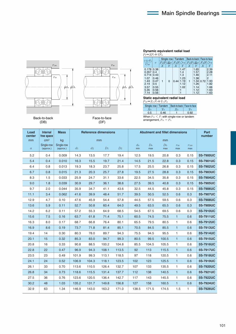
Main Spindle Bearings
101
0.178 0.357 0.714 1.07 1.43 2.14 3.57 5.35 7.14
eX Y
Dynamic equivalent radial loadPr=XFr+YFa
Static equivalent radial loadPor=Xo Fr+Yo Fa
Fa/Fr≦e Fa/Fr>eSingle row / Tandem Back-to-back / Face-to-face
Fa/Fr≦e Fa/Fr>eX Y X Y X Y
0.38 0.4 0.43 0.46 0.47 0.5 0.55 0.56 0.56
1 0 0.44
1.47 1.4 1.3 1.23 1.19 1.12 1.02 1 1
1
1.65 1.57 1.46 1.38 1.34 1.26 1.14 1.12 1.12
0.72
2.39 2.28 2.11 2 1.93 1.82 1.66 1.63 1.63
Xo
Single row / Tandem Back-to-back / Face-to-face
0.5Yo Xo Yo
0.46 1 0.92
Cor
i・fo・Fa
When Por < Fr with single-row or tandem arrangement, Por = Fr.
Load Internal Mass Reference dimensions Abutment and fillet dimensions Partcenter free space numbermm cm3 kg mm mm
Single-row Single-row da Da Db ras r1asa (approx.) (approx.) d1 d2 D1 D2 min max max max max
φDbφda
ras
r1as
φDaφda
ras
ras
Back-to-back (DB)
Face-to-face (DF)
5.2 0.4 0.009 14.3 13.5 17.7 19.4 12.5 19.5 20.8 0.3 0.15 5S-7900UC
5.4 0.4 0.010 16.3 15.5 19.7 21.4 14.5 21.5 22.8 0.3 0.15 5S-7901UC
6.4 0.8 0.013 19.3 18.3 23.7 25.8 17.5 25.5 26.8 0.3 0.15 5S-7902UC
6.7 0.8 0.015 21.3 20.3 25.7 27.8 19.5 27.5 28.8 0.3 0.15 5S-7903UC
8.3 1.5 0.033 25.9 24.7 31.1 33.6 22.5 34.5 35.8 0.3 0.15 5S-7904UC
9.0 1.8 0.039 30.9 29.7 36.1 38.6 27.5 39.5 40.8 0.3 0.15 5S-7905UC
9.7 2.0 0.044 35.9 34.7 41.1 43.6 32.5 44.5 45.8 0.3 0.15 5S-7906UC
11.1 3.4 0.062 41.6 39.9 48.4 51.7 39.5 50.5 52.5 0.6 0.3 5S-7907UC
12.9 4.7 0.10 47.6 45.9 54.4 57.8 44.5 57.5 59.5 0.6 0.3 5S-7908UC
13.6 5.9 0.11 52.7 50.8 60.4 64.0 49.5 63.5 65.5 0.6 0.3 5S-7909UC
14.2 6.2 0.11 57.2 55.3 64.9 68.5 54.5 67.5 69.5 0.6 0.3 5S-7910UC
15.6 7.5 0.16 63.7 61.8 71.4 75.1 60.5 74.5 75.5 1 0.6 5S-7911UC
16.3 8.0 0.17 68.7 66.8 76.4 80.1 65.5 79.5 80.5 1 0.6 5S-7912UC
16.9 8.6 0.19 73.7 71.8 81.4 85.1 70.5 84.5 85.5 1 0.6 5S-7913UC
19.4 14 0.30 80.3 78.0 89.7 94.3 75.5 94.5 95.5 1 0.6 5S-7914UC
20.1 15 0.32 85.3 83.0 94.7 99.3 80.5 99.5 100.5 1 0.6 5S-7915UC
20.8 16 0.33 90.8 88.5 100.2 104.8 85.5 104.5 105.5 1 0.6 5S-7916UC
22.8 22 0.47 96.9 94.3 108.1 113.5 92 113 115.5 1 0.6 5S-7917UC
23.5 23 0.49 101.9 99.3 113.1 118.5 97 118 120.5 1 0.6 5S-7918UC
24.1 24 0.52 106.9 104.3 118.1 123.5 102 123 125.5 1 0.6 5S-7919UC
26.1 33 0.70 113.6 110.5 126.4 132.7 107 133 135.5 1 0.6 5S-7920UC
26.8 34 0.73 118.6 115.5 131.4 137.7 112 138 140.5 1 0.6 5S-7921UC
27.5 36 0.76 123.6 120.5 136.4 142.7 117 143 145.5 1 0.6 5S-7922UC
30.2 48 1.03 135.2 131.7 149.8 156.8 127 158 160.5 1 0.6 5S-7924UC
32.9 63 1.34 146.9 143.0 163.2 171.0 138.5 171.5 174.5 1.5 1 5S-7926UC

Main Spindle Bearings
102
Standard angular contact ball bearings (ceramic ball type) 5S-79 series
Contact angle 25˚ d 10〜130mm
5S-7900UAD 10 22 6 0.3 0.15 3.05 1.10 310 112 2.12 216 73 200 120 100
5S-7901UAD 12 24 6 0.3 0.15 3.20 1.23 325 125 2.30 234 65 100 106 800
5S-7902UAD 15 28 7 0.3 0.15 4.85 1.92 495 196 3.35 345 54 500 89 400
5S-7903UAD 17 30 7 0.3 0.15 5.10 2.12 520 216 3.60 370 49 800 81 800
5S-7904UAD 20 37 9 0.3 0.15 7.25 3.25 740 330 5.60 575 41 100 67 400
5S-7905UAD 25 42 9 0.3 0.15 7.75 3.80 790 385 6.40 650 35 000 57 400
5S-7906UAD 30 47 9 0.3 0.15 8.15 4.35 830 445 7.15 730 30 400 49 900
5S-7907UAD 35 55 10 0.6 0.3 13.0 6.75 1 320 690 12.1 1 240 26 000 42 700
5S-7908UAD 40 62 12 0.6 0.3 13.7 7.75 1 400 790 13.6 1 380 23 000 37 700
5S-7909UAD 45 68 12 0.6 0.3 17.0 9.75 1 730 995 17.5 1 790 20 700 34 000
5S-7910UAD 50 72 12 0.6 0.3 17.9 10.9 1 820 1 110 19.3 1 970 19 200 31 500
5S-7911UAD 55 80 13 1 0.6 18.6 12.2 1 900 1 240 21.1 2 160 17 400 28 500
5S-7912UAD 60 85 13 1 0.6 19.4 13.3 1 970 1 360 23.0 2 340 16 200 26 500
5S-7913UAD 65 90 13 1 0.6 19.6 14.0 2 000 1 430 23.9 2 430 15 100 24 800
5S-7914UAD 70 100 16 1 0.6 28.0 19.8 2 860 2 020 33.5 3 400 13 800 22 600
5S-7915UAD 75 105 16 1 0.6 28.4 20.8 2 900 2 120 34.5 3 550 13 000 21 400
5S-7916UAD 80 110 16 1 0.6 28.7 21.7 2 930 2 220 36.0 3 700 12 300 20 100
5S-7917UAD 85 120 18 1.1 0.6 38.5 28.9 3 950 2 950 47.0 4 800 11 400 18 800
5S-7918UAD 90 125 18 1.1 0.6 39.5 30.0 4 000 3 100 49.0 5 000 10 900 17 900
5S-7919UAD 95 130 18 1.1 0.6 40.0 31.5 4 050 3 200 51.0 5 200 10 400 17 100
5S-7920UAD 100 140 20 1.1 0.6 51.0 40.0 5 200 4 100 67.5 6 850 9 800 16 000
5S-7921UAD 105 145 20 1.1 0.6 52.0 41.5 5 300 4 250 70.0 7 100 9 400 15 400
5S-7922UAD 110 150 20 1.1 0.6 52.5 43.5 5 400 4 450 72.5 7 400 9 000 14 800
5S-7924UAD 120 165 22 1.1 0.6 65.0 53.5 6 650 5 450 88.0 8 950 8 200 13 500
5S-7926UAD 130 180 24 1.5 1 80.0 66.5 8 150 6 800 112 11 400 7 600 12 400
Part Boundary dimensions Basic load ratings Static axial Limiting speednumber dynamic static dynamic static load capacity
mm kN kgf kN kgf min-1
grease oild D B rs min1 r1s min1 Cr Cor Cr Cor lubrication lubrication
φDφD1 φD2φd2 φdφd1
B
a
r1
rr
r
1 Minimum allowable value for corner radius dimension r or r1.
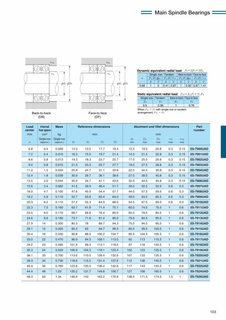
Main Spindle Bearings
103
X Y X Y X Y X Y0.68 1 0 0.41 0.87 1 0.92 0.67 1.41
Fa /Fr≦e Fa /Fr>e Fa /Fr≦e Fa /Fr>ee
Static equivalent radial load Por=Xo Fr+Yo Fa
When Por < Fr with single-row or tandem arrangement, Por = Fr.
Xo Yo Xo Yo
0.5 0.38 1 0.76
Dynamic equivalent radial load Pr=XFr+YFa
Single row / Tandem Back-to-back / Face-to-face
Single row / Tandem Back-to-back / Face-to-face
6.8 0.4 0.009 14.3 13.5 17.7 19.4 12.5 19.5 20.8 0.3 0.15 5S-7900UAD
7.2 0.4 0.010 16.3 15.5 19.7 21.4 14.5 21.5 22.8 0.3 0.15 5S-7901UAD
8.6 0.8 0.013 19.3 18.3 23.7 25.7 17.5 25.5 26.8 0.3 0.15 5S-7902UAD
9.0 0.8 0.015 21.3 20.3 25.7 27.7 19.5 27.5 28.8 0.3 0.15 5S-7903UAD
11.2 1.5 0.033 25.9 24.7 31.1 33.6 22.5 34.5 35.8 0.3 0.15 5S-7904UAD
12.4 1.8 0.039 30.9 29.7 36.1 38.6 27.5 39.5 40.8 0.3 0.15 5S-7905UAD
13.5 2.0 0.044 35.9 34.7 41.1 43.6 32.5 44.5 45.8 0.3 0.15 5S-7906UAD
15.6 3.4 0.062 41.6 39.9 48.4 51.7 39.5 50.5 52.5 0.6 0.3 5S-7907UAD
18.0 4.7 0.100 47.6 45.9 54.4 57.7 44.5 57.5 59.5 0.6 0.3 5S-7908UAD
19.2 5.9 0.110 52.7 50.8 60.4 64.0 49.5 63.5 65.5 0.6 0.3 5S-7909UAD
20.3 6.2 0.110 57.2 55.3 64.9 68.5 54.5 67.5 69.5 0.6 0.3 5S-7910UAD
22.3 7.5 0.160 63.7 61.8 71.4 75.1 60.5 74.5 75.5 1 0.6 5S-7911UAD
23.5 8.0 0.170 68.7 66.8 76.4 80.0 65.5 79.5 80.5 1 0.6 5S-7912UAD
24.6 8.6 0.190 73.7 71.8 81.4 85.0 70.5 84.5 85.5 1 0.6 5S-7913UAD
27.9 14 0.300 80.3 78 89.7 94.3 75.5 94.5 95.5 1 0.6 5S-7914UAD
29.1 15 0.320 85.3 83 94.7 99.3 80.5 99.5 100.5 1 0.6 5S-7915UAD
30.4 16 0.330 90.8 88.5 100.2 104.7 85.5 104.5 105.5 1 0.6 5S-7916UAD
33.0 22 0.470 96.9 94.3 108.1 113.5 92 113 115.5 1 0.6 5S-7917UAD
34.2 23 0.490 101.9 99.3 113.1 118.5 97 118 120.5 1 0.6 5S-7918UAD
35.3 24 0.520 106.9 104.3 118.1 123.4 102 123 125.5 1 0.6 5S-7919UAD
38.1 33 0.700 113.6 110.5 126.4 132.6 107 133 135.5 1 0.6 5S-7920UAD
39.3 34 0.730 118.6 115.5 131.4 137.6 112 138 140.5 1 0.6 5S-7921UAD
40.4 36 0.760 123.6 120.5 136.4 142.6 117 143 145.5 1 0.6 5S-7922UAD
44.4 48 1.03 135.2 131.7 149.8 156.7 127 158 160.5 1 0.6 5S-7924UAD
48.3 63 1.34 146.9 143 163.2 170.9 138.5 171.5 174.5 1.5 1 5S-7926UAD
Load Internal Mass Reference dimensions Abutment and fillet dimensions Part center free space numbermm cm3 kg mm mm
Single-row Single-row da Da Db ras r1asa (approx.) (approx.) d1 d2 D1 D2 min max max max max
φDbφda
ras
r1as
φDaφda
ras
ras
Back-to-back (DB)
Face-to-face (DF)
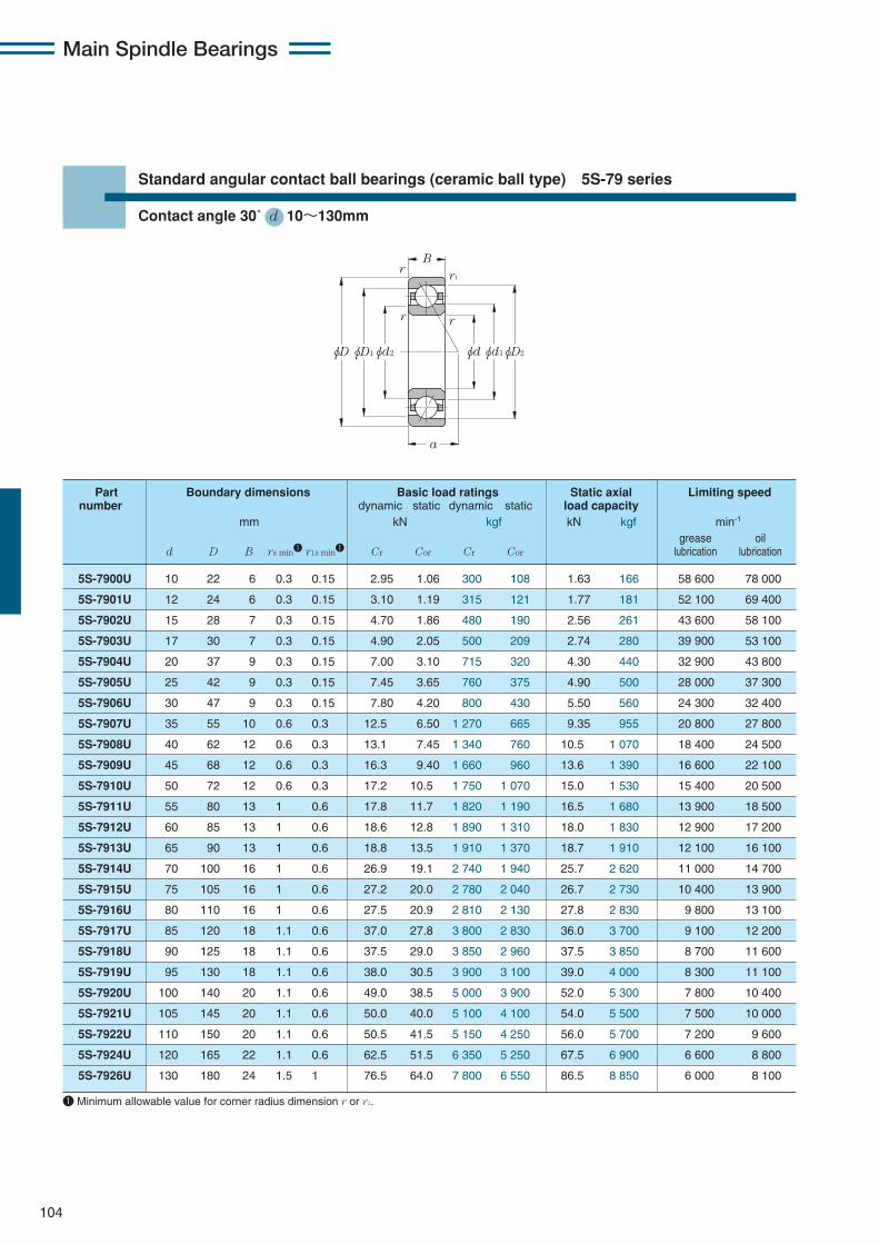
Main Spindle Bearings
104
Standard angular contact ball bearings (ceramic ball type) 5S-79 series
Contact angle 30˚ d 10〜130mm
5S-7900U 10 22 6 0.3 0.15 2.95 1.06 300 108 1.63 166 58 600 78 000
5S-7901U 12 24 6 0.3 0.15 3.10 1.19 315 121 1.77 181 52 100 69 400
5S-7902U 15 28 7 0.3 0.15 4.70 1.86 480 190 2.56 261 43 600 58 100
5S-7903U 17 30 7 0.3 0.15 4.90 2.05 500 209 2.74 280 39 900 53 100
5S-7904U 20 37 9 0.3 0.15 7.00 3.10 715 320 4.30 440 32 900 43 800
5S-7905U 25 42 9 0.3 0.15 7.45 3.65 760 375 4.90 500 28 000 37 300
5S-7906U 30 47 9 0.3 0.15 7.80 4.20 800 430 5.50 560 24 300 32 400
5S-7907U 35 55 10 0.6 0.3 12.5 6.50 1 270 665 9.35 955 20 800 27 800
5S-7908U 40 62 12 0.6 0.3 13.1 7.45 1 340 760 10.5 1 070 18 400 24 500
5S-7909U 45 68 12 0.6 0.3 16.3 9.40 1 660 960 13.6 1 390 16 600 22 100
5S-7910U 50 72 12 0.6 0.3 17.2 10.5 1 750 1 070 15.0 1 530 15 400 20 500
5S-7911U 55 80 13 1 0.6 17.8 11.7 1 820 1 190 16.5 1 680 13 900 18 500
5S-7912U 60 85 13 1 0.6 18.6 12.8 1 890 1 310 18.0 1 830 12 900 17 200
5S-7913U 65 90 13 1 0.6 18.8 13.5 1 910 1 370 18.7 1 910 12 100 16 100
5S-7914U 70 100 16 1 0.6 26.9 19.1 2 740 1 940 25.7 2 620 11 000 14 700
5S-7915U 75 105 16 1 0.6 27.2 20.0 2 780 2 040 26.7 2 730 10 400 13 900
5S-7916U 80 110 16 1 0.6 27.5 20.9 2 810 2 130 27.8 2 830 9 800 13 100
5S-7917U 85 120 18 1.1 0.6 37.0 27.8 3 800 2 830 36.0 3 700 9 100 12 200
5S-7918U 90 125 18 1.1 0.6 37.5 29.0 3 850 2 960 37.5 3 850 8 700 11 600
5S-7919U 95 130 18 1.1 0.6 38.0 30.5 3 900 3 100 39.0 4 000 8 300 11 100
5S-7920U 100 140 20 1.1 0.6 49.0 38.5 5 000 3 900 52.0 5 300 7 800 10 400
5S-7921U 105 145 20 1.1 0.6 50.0 40.0 5 100 4 100 54.0 5 500 7 500 10 000
5S-7922U 110 150 20 1.1 0.6 50.5 41.5 5 150 4 250 56.0 5 700 7 200 9 600
5S-7924U 120 165 22 1.1 0.6 62.5 51.5 6 350 5 250 67.5 6 900 6 600 8 800
5S-7926U 130 180 24 1.5 1 76.5 64.0 7 800 6 550 86.5 8 850 6 000 8 100
Part Boundary dimensions Basic load ratings Static axial Limiting speednumber dynamic static dynamic static load capacity
mm kN kgf kN kgf min-1
grease oild D B rs min1 r1s min1 Cr Cor Cr Cor lubrication lubrication
φDφD1 φD2φd2 φdφd1
B
a
r1
rr
r
1 Minimum allowable value for corner radius dimension r or r1.

Main Spindle Bearings
105
Load Internal Mass Reference dimensions Abutment and fillet dimensions Part center free space numbermm cm3 kg mm mm
Single-row Single-row da Da Db ras r1asa (approx.) (approx.) d1 d2 D1 D2 min max max max max
X Y X Y X Y X Y0.8 1 0 0.39 0.76 1 0.78 0.63 1.24
Fa /Fr≦e Fa /Fr>e Fa /Fr≦e Fa /Fr>eSingle row / Tandem Back-to-back / Face-to-face
e
Static equivalent radial load Por=Xo Fr+Yo Fa
When Por < Fr with single-row or tandem arrangement, Por = Fr.
Xo Yo Xo Yo
0.5 0.33 1 0.66
Single row / Tandem Back-to-back / Face-to-face
Dynamic equivalent radial load Pr=XFr+YFa
φDbφda
ras
r1as
φDaφda
ras
ras
Back-to-back (DB)
Face-to-face (DF)
7.7 0.4 0.009 14.3 13.5 17.7 19.3 12.5 19.5 20.8 0.3 0.15 5S-7900U
8.2 0.4 0.010 16.3 15.5 19.7 21.3 14.5 21.5 22.8 0.3 0.15 5S-7901U
9.8 0.8 0.013 19.3 18.3 23.7 25.7 17.5 25.5 26.8 0.3 0.15 5S-7902U
10.3 0.8 0.015 21.3 20.3 25.7 27.7 19.5 27.5 28.8 0.3 0.15 5S-7903U
12.8 1.5 0.033 25.9 24.7 31.1 33.5 22.5 34.5 35.8 0.3 0.15 5S-7904U
14.2 1.8 0.039 30.9 29.7 36.1 38.5 27.5 39.5 40.8 0.3 0.15 5S-7905U
15.7 2.0 0.044 35.9 34.7 41.1 43.5 32.5 44.5 45.8 0.3 0.15 5S-7906U
18.1 3.4 0.062 41.6 39.9 48.4 51.6 39.5 50.5 52.5 0.6 0.3 5S-7907U
20.8 4.7 0.10 47.6 45.9 54.4 57.7 44.5 57.5 59.5 0.6 0.3 5S-7908U
22.4 5.9 0.11 52.7 50.8 60.4 64.0 49.5 63.5 65.5 0.6 0.3 5S-7909U
23.7 6.2 0.11 57.2 55.3 64.9 68.4 54.5 67.5 69.5 0.6 0.3 5S-7910U
26.1 7.5 0.16 63.7 61.8 71.4 75.0 60.5 74.5 75.5 1 0.6 5S-7911U
27.5 8.0 0.17 68.7 66.8 76.4 80.0 65.5 79.5 80.5 1 0.6 5S-7912U
29.0 8.6 0.19 73.7 71.8 81.4 85.0 70.5 84.5 85.5 1 0.6 5S-7913U
32.6 14 0.30 80.3 78.0 89.7 94.2 75.5 94.5 95.5 1 0.6 5S-7914U
34.1 15 0.32 85.3 83.0 94.7 99.2 80.5 99.5 100.5 1 0.6 5S-7915U
35.7 16 0.30 90.8 88.5 100.2 104.7 85.5 104.5 105.5 1 0.6 5S-7916U
38.7 22 0.47 96.9 94.3 108.1 113.4 92 113 115.5 1 0.6 5S-7917U
40.2 23 0.49 101.9 99.3 113.1 118.4 97 118 120.5 1 0.6 5S-7918U
41.6 24 0.52 106.9 104.3 118.1 123.4 102 123 125.5 1 0.6 5S-7919U
44.8 33 0.70 113.6 110.5 126.4 132.6 107 133 135.5 1 0.6 5S-7920U
46.2 34 0.73 118.6 115.5 131.4 137.6 112 138 140.5 1 0.6 5S-7921U
47.7 36 0.76 123.6 120.5 136.4 142.6 117 143 145.5 1 0.6 5S-7922U
52.3 48 1.03 135.2 131.7 149.8 156.7 127 158 160.5 1 0.6 5S-7924U
56.9 63 1.34 146.9 143.0 163.2 170.9 138.5 171.5 174.5 1.5 1 5S-7926U
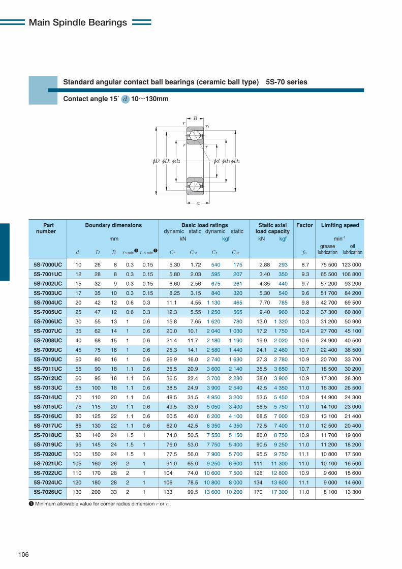
Main Spindle Bearings
106
Standard angular contact ball bearings (ceramic ball type) 5S-70 series
Contact angle 15˚ d 10〜130mm
5S-7000UC 10 26 8 0.3 0.15 5.30 1.72 540 175 2.88 293 8.7 75 500 123 000
5S-7001UC 12 28 8 0.3 0.15 5.80 2.03 595 207 3.40 350 9.3 65 500 106 800
5S-7002UC 15 32 9 0.3 0.15 6.60 2.56 675 261 4.35 440 9.7 57 200 93 200
5S-7003UC 17 35 10 0.3 0.15 8.25 3.15 840 320 5.30 540 9.6 51 700 84 200
5S-7004UC 20 42 12 0.6 0.3 11.1 4.55 1 130 465 7.70 785 9.8 42 700 69 500
5S-7005UC 25 47 12 0.6 0.3 12.3 5.55 1 250 565 9.40 960 10.2 37 300 60 800
5S-7006UC 30 55 13 1 0.6 15.8 7.65 1 620 780 13.0 1 320 10.3 31 200 50 900
5S-7007UC 35 62 14 1 0.6 20.0 10.1 2 040 1 030 17.2 1 750 10.4 27 700 45 100
5S-7008UC 40 68 15 1 0.6 21.4 11.7 2 180 1 190 19.9 2 020 10.6 24 900 40 500
5S-7009UC 45 75 16 1 0.6 25.3 14.1 2 580 1 440 24.1 2 460 10.7 22 400 36 500
5S-7010UC 50 80 16 1 0.6 26.9 16.0 2 740 1 630 27.3 2 780 10.9 20 700 33 700
5S-7011UC 55 90 18 1.1 0.6 35.5 20.9 3 600 2 140 35.5 3 650 10.7 18 500 30 200
5S-7012UC 60 95 18 1.1 0.6 36.5 22.4 3 700 2 280 38.0 3 900 10.9 17 300 28 300
5S-7013UC 65 100 18 1.1 0.6 38.5 24.9 3 900 2 540 42.5 4 350 11.0 16 300 26 500
5S-7014UC 70 110 20 1.1 0.6 48.5 31.5 4 950 3 200 53.5 5 450 10.9 14 900 24 300
5S-7015UC 75 115 20 1.1 0.6 49.5 33.0 5 050 3 400 56.5 5 750 11.0 14 100 23 000
5S-7016UC 80 125 22 1.1 0.6 60.5 40.0 6 200 4 100 68.5 7 000 10.9 13 100 21 400
5S-7017UC 85 130 22 1.1 0.6 62.0 42.5 6 350 4 350 72.5 7 400 11.0 12 500 20 400
5S-7018UC 90 140 24 1.5 1 74.0 50.5 7 550 5 150 86.0 8 750 10.9 11 700 19 000
5S-7019UC 95 145 24 1.5 1 76.0 53.0 7 750 5 400 90.5 9 250 11.0 11 200 18 200
5S-7020UC 100 150 24 1.5 1 77.5 56.0 7 900 5 700 95.5 9 750 11.1 10 800 17 500
5S-7021UC 105 160 26 2 1 91.0 65.0 9 250 6 600 111 11 300 11.0 10 100 16 500
5S-7022UC 110 170 28 2 1 104 74.0 10 600 7 500 126 12 800 10.9 9 600 15 600
5S-7024UC 120 180 28 2 1 106 78.5 10 800 8 000 134 13 600 11.1 9 000 14 600
5S-7026UC 130 200 33 2 1 133 99.5 13 600 10 200 170 17 300 11.0 8 100 13 300
Part Boundary dimensions Basic load ratings Static axial Factor Limiting speednumber dynamic static dynamic static load capacity
mm kN kgf kN kgf min-1
grease oild D B rs min1 r1s min1 Cr Cor Cr Cor fo lubrication lubrication
φDφD1 φD2φd2 φdφd1
B
a
r1
rr
r
1 Minimum allowable value for corner radius dimension r or r1.
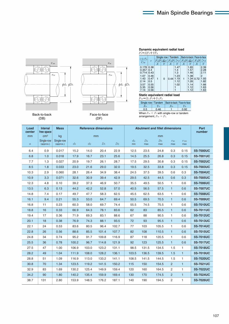
Main Spindle Bearings
107
0.178 0.357 0.714 1.07 1.43 2.14 3.57 5.35 7.14
eX Y
Dynamic equivalent radial loadPr=XFr+YFa
Static equivalent radial loadPor=Xo Fr+Yo Fa
Fa/Fr≦e Fa/Fr>eSingle row / Tandem Back-to-back / Face-to-face
Fa/Fr≦e Fa/Fr>eX Y X Y X Y
0.38 0.4 0.43 0.46 0.47 0.5 0.55 0.56 0.56
1 0 0.44
1.47 1.4 1.3 1.23 1.19 1.12 1.02 1 1
1
1.65 1.57 1.46 1.38 1.34 1.26 1.14 1.12 1.12
0.72
2.39 2.28 2.11 2 1.93 1.82 1.66 1.63 1.63
Xo
Single row / Tandem Back-to-back / Face-to-face
0.5Yo Xo Yo
0.46 1 0.92
Cor
i・fo・Fa
When Por < Fr with single-row or tandem arrangement, Por = Fr.
Load Internal Mass Reference dimensions Abutment and fillet dimensions Partcenter free space numbermm cm3 kg mm mm
Single-row Single-row da Da Db ras r1asa (approx.) (approx.) d1 d2 D1 D2 min max max max max
φDbφda
ras
r1as
φDaφda
ras
ras
Back-to-back (DB)
Face-to-face (DF)
6.4 0.9 0.017 15.2 14.0 20.4 22.9 12.5 23.5 24.8 0.3 0.15 5S-7000UC
6.8 1.0 0.018 17.9 16.7 23.1 25.6 14.5 25.5 26.8 0.3 0.15 5S-7001UC
7.7 1.3 0.027 20.9 19.7 26.1 28.7 17.5 29.5 30.8 0.3 0.15 5S-7002UC
8.5 1.8 0.033 23.0 21.6 29.0 32.0 19.5 32.5 33.8 0.3 0.15 5S-7003UC
10.3 2.9 0.060 28.1 26.4 34.9 38.4 24.5 37.5 39.5 0.6 0.3 5S-7004UC
10.9 3.3 0.071 32.6 30.9 39.4 42.9 29.5 42.5 44.5 0.6 0.3 5S-7005UC
12.3 4.8 0.10 39.2 37.3 46.9 50.7 35.5 49.5 50.5 1 0.6 5S-7006UC
13.5 6.3 0.13 44.2 42.2 52.8 57.0 40.5 56.5 57.5 1 0.6 5S-7007UC
14.8 7.4 0.17 49.7 47.7 58.3 62.5 45.5 62.5 63.5 1 0.6 5S-7008UC
16.1 9.4 0.21 55.3 53.0 64.7 69.4 50.5 69.5 70.5 1 0.6 5S-7009UC
16.8 11 0.23 60.3 58.0 69.7 74.4 55.5 74.5 75.5 1 0.6 5S-7010UC
18.8 16 0.33 66.9 64.3 78.1 83.6 62 83 85.5 1 0.6 5S-7011UC
19.4 17 0.36 71.9 69.3 83.1 88.6 67 88 90.5 1 0.6 5S-7012UC
20.1 18 0.38 76.9 74.3 88.1 93.5 72 93 95.5 1 0.6 5S-7013UC
22.1 24 0.53 83.6 80.5 96.4 102.7 77 103 105.5 1 0.6 5S-7014UC
22.8 26 0.56 88.6 85.5 101.4 107.7 82 108 110.5 1 0.6 5S-7015UC
24.8 34 0.74 95.2 91.7 109.8 116.9 87 118 120.5 1 0.6 5S-7016UC
25.5 36 0.78 100.2 96.7 114.8 121.9 92 123 125.5 1 0.6 5S-7017UC
27.5 47 1.00 106.9 103.0 123.2 131.1 98.5 131.5 134.5 1.5 1 5S-7018UC
28.2 49 1.04 111.9 108.0 128.2 136.1 103.5 136.5 139.5 1.5 1 5S-7019UC
28.8 51 1.09 116.9 113.0 133.2 141.1 108.5 141.5 144.5 1.5 1 5S-7020UC
30.8 70 1.34 123.5 119.2 141.5 150.2 115 150 154.5 2 1 5S-7021UC
32.9 83 1.69 130.2 125.4 149.9 159.4 120 160 164.5 2 1 5S-7022UC
34.2 90 1.80 140.2 135.4 159.9 169.4 130 170 174.5 2 1 5S-7024UC
38.7 131 2.80 153.9 148.5 176.2 187.1 140 190 194.5 2 1 5S-7026UC
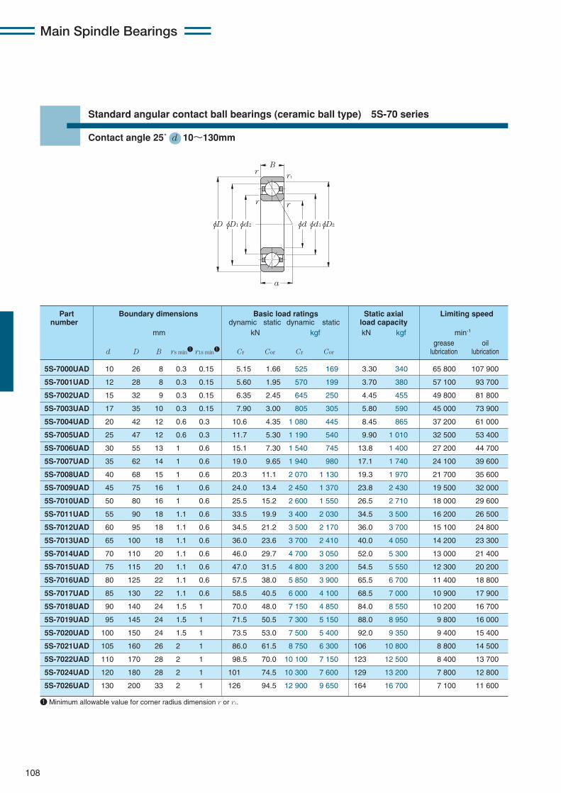
Main Spindle Bearings
108
Standard angular contact ball bearings (ceramic ball type) 5S-70 series
Contact angle 25˚ d 10〜130mm
5S-7000UAD 10 26 8 0.3 0.15 5.15 1.66 525 169 3.30 340 65 800 107 900
5S-7001UAD 12 28 8 0.3 0.15 5.60 1.95 570 199 3.70 380 57 100 93 700
5S-7002UAD 15 32 9 0.3 0.15 6.35 2.45 645 250 4.45 455 49 800 81 800
5S-7003UAD 17 35 10 0.3 0.15 7.90 3.00 805 305 5.80 590 45 000 73 900
5S-7004UAD 20 42 12 0.6 0.3 10.6 4.35 1 080 445 8.45 865 37 200 61 000
5S-7005UAD 25 47 12 0.6 0.3 11.7 5.30 1 190 540 9.90 1 010 32 500 53 400
5S-7006UAD 30 55 13 1 0.6 15.1 7.30 1 540 745 13.8 1 400 27 200 44 700
5S-7007UAD 35 62 14 1 0.6 19.0 9.65 1 940 980 17.1 1 740 24 100 39 600
5S-7008UAD 40 68 15 1 0.6 20.3 11.1 2 070 1 130 19.3 1 970 21 700 35 600
5S-7009UAD 45 75 16 1 0.6 24.0 13.4 2 450 1 370 23.8 2 430 19 500 32 000
5S-7010UAD 50 80 16 1 0.6 25.5 15.2 2 600 1 550 26.5 2 710 18 000 29 600
5S-7011UAD 55 90 18 1.1 0.6 33.5 19.9 3 400 2 030 34.5 3 500 16 200 26 500
5S-7012UAD 60 95 18 1.1 0.6 34.5 21.2 3 500 2 170 36.0 3 700 15 100 24 800
5S-7013UAD 65 100 18 1.1 0.6 36.0 23.6 3 700 2 410 40.0 4 050 14 200 23 300
5S-7014UAD 70 110 20 1.1 0.6 46.0 29.7 4 700 3 050 52.0 5 300 13 000 21 400
5S-7015UAD 75 115 20 1.1 0.6 47.0 31.5 4 800 3 200 54.5 5 550 12 300 20 200
5S-7016UAD 80 125 22 1.1 0.6 57.5 38.0 5 850 3 900 65.5 6 700 11 400 18 800
5S-7017UAD 85 130 22 1.1 0.6 58.5 40.5 6 000 4 100 68.5 7 000 10 900 17 900
5S-7018UAD 90 140 24 1.5 1 70.0 48.0 7 150 4 850 84.0 8 550 10 200 16 700
5S-7019UAD 95 145 24 1.5 1 71.5 50.5 7 300 5 150 88.0 8 950 9 800 16 000
5S-7020UAD 100 150 24 1.5 1 73.5 53.0 7 500 5 400 92.0 9 350 9 400 15 400
5S-7021UAD 105 160 26 2 1 86.0 61.5 8 750 6 300 106 10 800 8 800 14 500
5S-7022UAD 110 170 28 2 1 98.5 70.0 10 100 7 150 123 12 500 8 400 13 700
5S-7024UAD 120 180 28 2 1 101 74.5 10 300 7 600 129 13 200 7 800 12 800
5S-7026UAD 130 200 33 2 1 126 94.5 12 900 9 650 164 16 700 7 100 11 600
Part Boundary dimensions Basic load ratings Static axial Limiting speednumber dynamic static dynamic static load capacity
mm kN kgf kN kgf min-1
grease oild D B rs min1 r1s min1 Cr Cor Cr Cor lubrication lubrication
φDφD1 φD2φd2 φdφd1
B
a
r1
rr
r
1 Minimum allowable value for corner radius dimension r or r1.
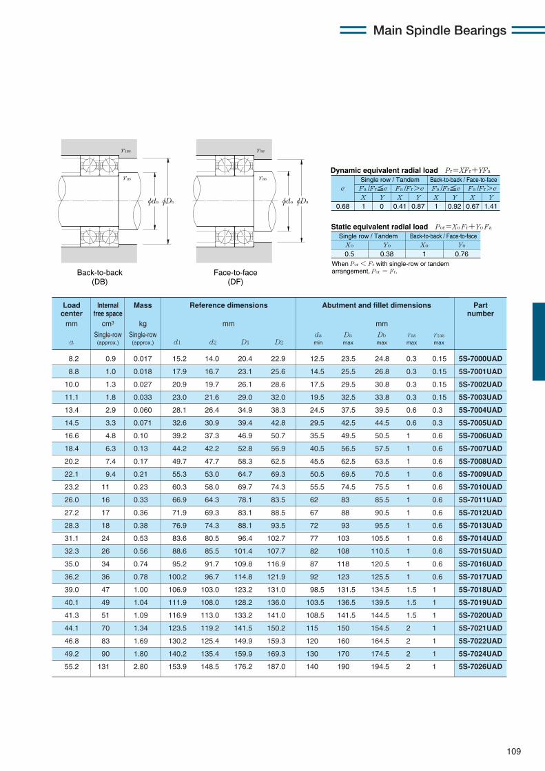
Main Spindle Bearings
109
Load Internal Mass Reference dimensions Abutment and fillet dimensions Part center free space numbermm cm3 kg mm mm
Single-row Single-row da Da Db ras r1asa (approx.) (approx.) d1 d2 D1 D2 min max max max max
X Y X Y X Y X Y0.68 1 0 0.41 0.87 1 0.92 0.67 1.41
Fa /Fr≦e Fa /Fr>e Fa /Fr≦e Fa /Fr>ee
Static equivalent radial load Por=Xo Fr+Yo Fa
When Por < Fr with single-row or tandem arrangement, Por = Fr.
Xo Yo Xo Yo
0.5 0.38 1 0.76
Dynamic equivalent radial load Pr=XFr+YFa
Single row / Tandem Back-to-back / Face-to-face
Single row / Tandem Back-to-back / Face-to-face
φDbφda
ras
r1as
φDaφda
ras
ras
Back-to-back (DB)
Face-to-face (DF)
8.2 0.9 0.017 15.2 14.0 20.4 22.9 12.5 23.5 24.8 0.3 0.15 5S-7000UAD
8.8 1.0 0.018 17.9 16.7 23.1 25.6 14.5 25.5 26.8 0.3 0.15 5S-7001UAD
10.0 1.3 0.027 20.9 19.7 26.1 28.6 17.5 29.5 30.8 0.3 0.15 5S-7002UAD
11.1 1.8 0.033 23.0 21.6 29.0 32.0 19.5 32.5 33.8 0.3 0.15 5S-7003UAD
13.4 2.9 0.060 28.1 26.4 34.9 38.3 24.5 37.5 39.5 0.6 0.3 5S-7004UAD
14.5 3.3 0.071 32.6 30.9 39.4 42.8 29.5 42.5 44.5 0.6 0.3 5S-7005UAD
16.6 4.8 0.10 39.2 37.3 46.9 50.7 35.5 49.5 50.5 1 0.6 5S-7006UAD
18.4 6.3 0.13 44.2 42.2 52.8 56.9 40.5 56.5 57.5 1 0.6 5S-7007UAD
20.2 7.4 0.17 49.7 47.7 58.3 62.5 45.5 62.5 63.5 1 0.6 5S-7008UAD
22.1 9.4 0.21 55.3 53.0 64.7 69.3 50.5 69.5 70.5 1 0.6 5S-7009UAD
23.2 11 0.23 60.3 58.0 69.7 74.3 55.5 74.5 75.5 1 0.6 5S-7010UAD
26.0 16 0.33 66.9 64.3 78.1 83.5 62 83 85.5 1 0.6 5S-7011UAD
27.2 17 0.36 71.9 69.3 83.1 88.5 67 88 90.5 1 0.6 5S-7012UAD
28.3 18 0.38 76.9 74.3 88.1 93.5 72 93 95.5 1 0.6 5S-7013UAD
31.1 24 0.53 83.6 80.5 96.4 102.7 77 103 105.5 1 0.6 5S-7014UAD
32.3 26 0.56 88.6 85.5 101.4 107.7 82 108 110.5 1 0.6 5S-7015UAD
35.0 34 0.74 95.2 91.7 109.8 116.9 87 118 120.5 1 0.6 5S-7016UAD
36.2 36 0.78 100.2 96.7 114.8 121.9 92 123 125.5 1 0.6 5S-7017UAD
39.0 47 1.00 106.9 103.0 123.2 131.0 98.5 131.5 134.5 1.5 1 5S-7018UAD
40.1 49 1.04 111.9 108.0 128.2 136.0 103.5 136.5 139.5 1.5 1 5S-7019UAD
41.3 51 1.09 116.9 113.0 133.2 141.0 108.5 141.5 144.5 1.5 1 5S-7020UAD
44.1 70 1.34 123.5 119.2 141.5 150.2 115 150 154.5 2 1 5S-7021UAD
46.8 83 1.69 130.2 125.4 149.9 159.3 120 160 164.5 2 1 5S-7022UAD
49.2 90 1.80 140.2 135.4 159.9 169.3 130 170 174.5 2 1 5S-7024UAD
55.2 131 2.80 153.9 148.5 176.2 187.0 140 190 194.5 2 1 5S-7026UAD

Main Spindle Bearings
110
Standard angular contact ball bearings (ceramic ball type) 5S-70 series
Contact angle 30˚ d 10〜130mm
5S-7000U 10 26 8 0.3 0.15 5.00 1.62 510 165 2.54 259 52 600 70 100
5S-7001U 12 28 8 0.3 0.15 5.45 1.90 555 193 2.84 289 45 700 60 900
5S-7002U 15 32 9 0.3 0.15 6.15 2.38 625 242 3.40 350 39 900 53 100
5S-7003U 17 35 10 0.3 0.15 7.65 2.92 780 298 4.45 455 36 000 48 000
5S-7004U 20 42 12 0.6 0.3 10.3 4.25 1 050 430 6.55 670 29 700 39 600
5S-7005U 25 47 12 0.6 0.3 11.3 5.10 1 150 520 7.65 780 26 000 34 700
5S-7006U 30 55 13 1 0.6 14.5 7.05 1 480 715 10.7 1 090 21 800 29 000
5S-7007U 35 62 14 1 0.6 18.3 9.30 1 870 950 13.2 1 340 19 300 25 700
5S-7008U 40 68 15 1 0.6 19.5 10.7 1 990 1 090 14.8 1 510 17 400 23 100
5S-7009U 45 75 16 1 0.6 23.1 13.0 2 360 1 320 18.4 1 870 15 600 20 800
5S-7010U 50 80 16 1 0.6 24.5 14.6 2 500 1 490 20.5 2 090 14 400 19 200
5S-7011U 55 90 18 1.1 0.6 32.5 19.2 3 300 1 960 26.3 2 680 12 900 17 200
5S-7012U 60 95 18 1.1 0.6 33.0 20.5 3 350 2 090 27.7 2 830 12 100 16 100
5S-7013U 65 100 18 1.1 0.6 35.0 22.8 3 550 2 320 30.5 3 100 11 400 15 100
5S-7014U 70 110 20 1.1 0.6 44.0 28.6 4 500 2 920 40.0 4 100 10 400 13 900
5S-7015U 75 115 20 1.1 0.6 45.0 30.5 4 600 3 100 42.0 4 300 9 900 13 100
5S-7016U 80 125 22 1.1 0.6 55.0 37.0 5 600 3 750 50.5 5 150 9 100 12 200
5S-7017U 85 130 22 1.1 0.6 56.5 39.0 5 750 3 950 53.0 5 400 8 700 11 600
5S-7018U 90 140 24 1.5 1 67.5 46.0 6 850 4 700 64.5 6 600 8 200 10 900
5S-7019U 95 145 24 1.5 1 69.0 48.5 7 050 4 950 68.0 6 900 7 800 10 400
5S-7020U 100 150 24 1.5 1 70.5 51.0 7 200 5 200 71.0 7 250 7 500 10 000
5S-7021U 105 160 26 2 1 82.5 59.5 8 400 6 050 81.0 8 300 7 100 9 400
5S-7022U 110 170 28 2 1 95.0 67.5 9 650 6 900 95.0 9 700 6 700 8 900
5S-7024U 120 180 28 2 1 96.5 71.5 9 850 7 300 99.5 10 200 6 200 8 300
5S-7026U 130 200 33 2 1 121 91.0 12 300 9 300 126 12 900 5 700 7 600
Part Boundary dimensions Basic load ratings Static axial Limiting speednumber dynamic static dynamic static load capacity
mm kN kgf kN kgf min-1
grease oild D B rs min1 r1s min1 Cr Cor Cr Cor lubrication lubrication
φDφD1 φD2φd2 φdφd1
B
a
r1
rr
r
1 Minimum allowable value for corner radius dimension r or r1.
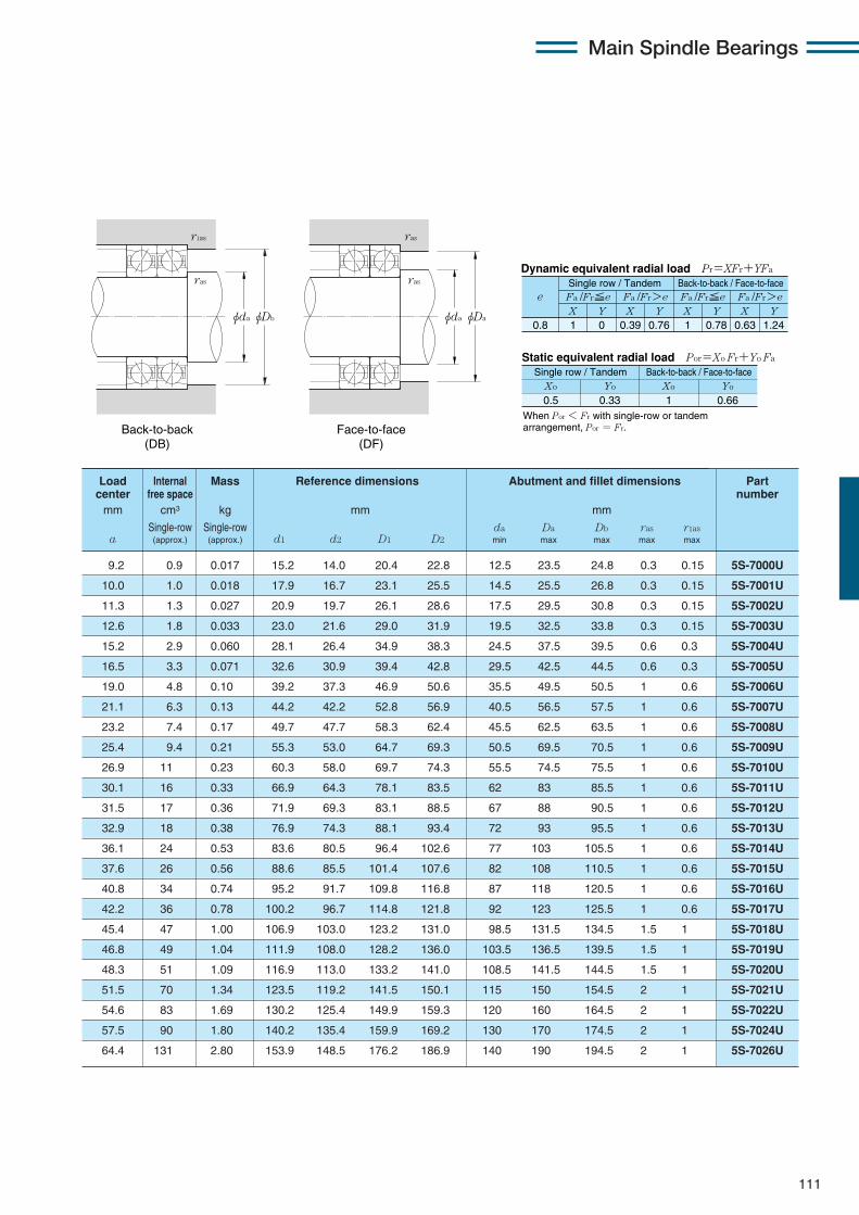
Main Spindle Bearings
111
Load Internal Mass Reference dimensions Abutment and fillet dimensions Partcenter free space numbermm cm3 kg mm mm
Single-row Single-row da Da Db ras r1asa (approx.) (approx.) d1 d2 D1 D2 min max max max max
X Y X Y X Y X Y0.8 1 0 0.39 0.76 1 0.78 0.63 1.24
Fa /Fr≦e Fa /Fr>e Fa /Fr≦e Fa /Fr>eSingle row / Tandem Back-to-back / Face-to-face
e
Static equivalent radial load Por=Xo Fr+Yo Fa
When Por < Fr with single-row or tandem arrangement, Por = Fr.
Xo Yo Xo Yo
0.5 0.33 1 0.66
Single row / Tandem Back-to-back / Face-to-face
Dynamic equivalent radial load Pr=XFr+YFa
φDbφda
ras
r1as
φDaφda
ras
ras
Back-to-back (DB)
Face-to-face (DF)
9.2 0.9 0.017 15.2 14.0 20.4 22.8 12.5 23.5 24.8 0.3 0.15 5S-7000U
10.0 1.0 0.018 17.9 16.7 23.1 25.5 14.5 25.5 26.8 0.3 0.15 5S-7001U
11.3 1.3 0.027 20.9 19.7 26.1 28.6 17.5 29.5 30.8 0.3 0.15 5S-7002U
12.6 1.8 0.033 23.0 21.6 29.0 31.9 19.5 32.5 33.8 0.3 0.15 5S-7003U
15.2 2.9 0.060 28.1 26.4 34.9 38.3 24.5 37.5 39.5 0.6 0.3 5S-7004U
16.5 3.3 0.071 32.6 30.9 39.4 42.8 29.5 42.5 44.5 0.6 0.3 5S-7005U
19.0 4.8 0.10 39.2 37.3 46.9 50.6 35.5 49.5 50.5 1 0.6 5S-7006U
21.1 6.3 0.13 44.2 42.2 52.8 56.9 40.5 56.5 57.5 1 0.6 5S-7007U
23.2 7.4 0.17 49.7 47.7 58.3 62.4 45.5 62.5 63.5 1 0.6 5S-7008U
25.4 9.4 0.21 55.3 53.0 64.7 69.3 50.5 69.5 70.5 1 0.6 5S-7009U
26.9 11 0.23 60.3 58.0 69.7 74.3 55.5 74.5 75.5 1 0.6 5S-7010U
30.1 16 0.33 66.9 64.3 78.1 83.5 62 83 85.5 1 0.6 5S-7011U
31.5 17 0.36 71.9 69.3 83.1 88.5 67 88 90.5 1 0.6 5S-7012U
32.9 18 0.38 76.9 74.3 88.1 93.4 72 93 95.5 1 0.6 5S-7013U
36.1 24 0.53 83.6 80.5 96.4 102.6 77 103 105.5 1 0.6 5S-7014U
37.6 26 0.56 88.6 85.5 101.4 107.6 82 108 110.5 1 0.6 5S-7015U
40.8 34 0.74 95.2 91.7 109.8 116.8 87 118 120.5 1 0.6 5S-7016U
42.2 36 0.78 100.2 96.7 114.8 121.8 92 123 125.5 1 0.6 5S-7017U
45.4 47 1.00 106.9 103.0 123.2 131.0 98.5 131.5 134.5 1.5 1 5S-7018U
46.8 49 1.04 111.9 108.0 128.2 136.0 103.5 136.5 139.5 1.5 1 5S-7019U
48.3 51 1.09 116.9 113.0 133.2 141.0 108.5 141.5 144.5 1.5 1 5S-7020U
51.5 70 1.34 123.5 119.2 141.5 150.1 115 150 154.5 2 1 5S-7021U
54.6 83 1.69 130.2 125.4 149.9 159.3 120 160 164.5 2 1 5S-7022U
57.5 90 1.80 140.2 135.4 159.9 169.2 130 170 174.5 2 1 5S-7024U
64.4 131 2.80 153.9 148.5 176.2 186.9 140 190 194.5 2 1 5S-7026U
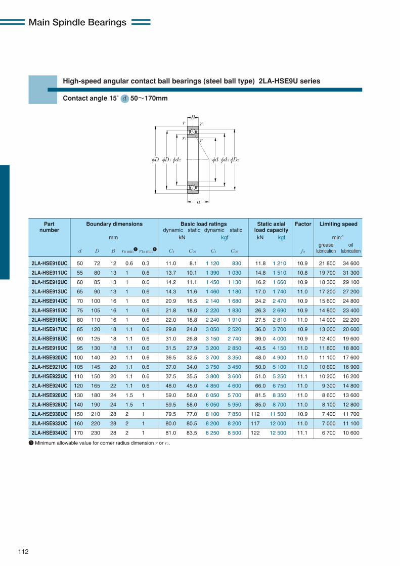
Main Spindle Bearings
112
High-speed angular contact ball bearings (steel ball type) 2LA-HSE9U series
Contact angle 15˚ d 50〜170mm
φD φD1 φD2φd2 φdφd1
B
a
r1
rr1
r
2LA-HSE910UC 50 72 12 0.6 0.3 11.0 8.1 1 120 830 11.8 1 210 10.9 21 800 34 600
2LA-HSE911UC 55 80 13 1 0.6 13.7 10.1 1 390 1 030 14.8 1 510 10.8 19 700 31 300
2LA-HSE912UC 60 85 13 1 0.6 14.2 11.1 1 450 1 130 16.2 1 660 10.9 18 300 29 100
2LA-HSE913UC 65 90 13 1 0.6 14.3 11.6 1 460 1 180 17.0 1 740 11.0 17 200 27 200
2LA-HSE914UC 70 100 16 1 0.6 20.9 16.5 2 140 1 680 24.2 2 470 10.9 15 600 24 800
2LA-HSE915UC 75 105 16 1 0.6 21.8 18.0 2 220 1 830 26.3 2 690 10.9 14 800 23 400
2LA-HSE916UC 80 110 16 1 0.6 22.0 18.8 2 240 1 910 27.5 2 810 11.0 14 000 22 200
2LA-HSE917UC 85 120 18 1.1 0.6 29.8 24.8 3 050 2 520 36.0 3 700 10.9 13 000 20 600
2LA-HSE918UC 90 125 18 1.1 0.6 31.0 26.8 3 150 2 740 39.0 4 000 10.9 12 400 19 600
2LA-HSE919UC 95 130 18 1.1 0.6 31.5 27.9 3 200 2 850 40.5 4 150 11.0 11 800 18 800
2LA-HSE920UC 100 140 20 1.1 0.6 36.5 32.5 3 700 3 350 48.0 4 900 11.0 11 100 17 600
2LA-HSE921UC 105 145 20 1.1 0.6 37.0 34.0 3 750 3 450 50.0 5 100 11.0 10 600 16 900
2LA-HSE922UC 110 150 20 1.1 0.6 37.5 35.5 3 800 3 600 51.0 5 250 11.1 10 200 16 200
2LA-HSE924UC 120 165 22 1.1 0.6 48.0 45.0 4 850 4 600 66.0 6 750 11.0 9 300 14 800
2LA-HSE926UC 130 180 24 1.5 1 59.0 56.0 6 050 5 700 81.5 8 350 11.0 8 600 13 600
2LA-HSE928UC 140 190 24 1.5 1 59.5 58.0 6 050 5 950 85.0 8 700 11.0 8 100 12 800
2LA-HSE930UC 150 210 28 2 1 79.5 77.0 8 100 7 850 112 11 500 10.9 7 400 11 700
2LA-HSE932UC 160 220 28 2 1 80.0 80.5 8 200 8 200 117 12 000 11.0 7 000 11 100
2LA-HSE934UC 170 230 28 2 1 81.0 83.5 8 250 8 500 122 12 500 11.1 6 700 10 600
Part Boundary dimensions Basic load ratings Static axial Factor Limiting speednumber dynamic static dynamic static load capacity
mm kN kgf kN kgf min-1
grease oild D B rs min1 r1s min1 Cr Cor Cr Cor fo lubrication lubrication
1 Minimum allowable value for corner radius dimension r or r1.
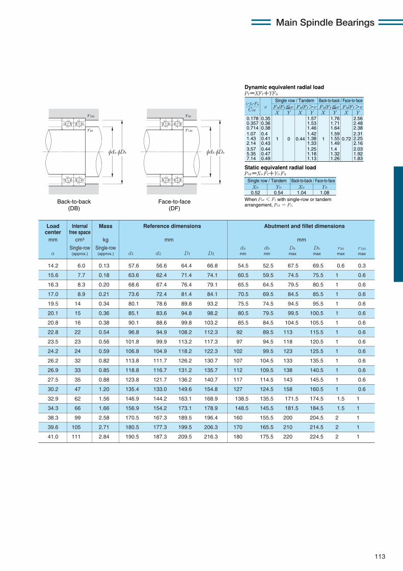
Main Spindle Bearings
113
0.178 0.357 0.714 1.07 1.43 2.14 3.57 5.35 7.14
eX Y
Dynamic equivalent radial loadPr=XFr+YFa
Static equivalent radial loadPor=Xo Fr+Yo Fa
Fa/Fr≦e Fa/Fr>e Fa/Fr≦e Fa/Fr>eX Y X Y X Y
0.35 0.36 0.38 0.4 0.41 0.43 0.44 0.47 0.49
1 0 0.44
1.57 1.53 1.46 1.42 1.38 1.33 1.25 1.18 1.13
1
1.76 1.71 1.64 1.59 1.55 1.49 1.4 1.32 1.26
0.72
2.56 2.48 2.38 2.31 2.25 2.16 2.03 1.92 1.83
When Por < Fr with single-row or tandem arrangement, Por = Fr.
Xo0.52
Yo Xo Yo0.54 1.04 1.08
Cor
i・fo・Fa
Single row / Tandem Back-to-back / Face-to-face
Single row / Tandem Back-to-back / Face-to-face
14.2 6.0 0.13 57.6 56.6 64.4 66.8 54.5 52.5 67.5 69.5 0.6 0.3
15.6 7.7 0.18 63.6 62.4 71.4 74.1 60.5 59.5 74.5 75.5 1 0.6
16.3 8.3 0.20 68.6 67.4 76.4 79.1 65.5 64.5 79.5 80.5 1 0.6
17.0 8.9 0.21 73.6 72.4 81.4 84.1 70.5 69.5 84.5 85.5 1 0.6
19.5 14 0.34 80.1 78.6 89.8 93.2 75.5 74.5 94.5 95.5 1 0.6
20.1 15 0.36 85.1 83.6 94.8 98.2 80.5 79.5 99.5 100.5 1 0.6
20.8 16 0.38 90.1 88.6 99.8 103.2 85.5 84.5 104.5 105.5 1 0.6
22.8 22 0.54 96.8 94.9 108.2 112.3 92 89.5 113 115.5 1 0.6
23.5 23 0.56 101.8 99.9 113.2 117.3 97 94.5 118 120.5 1 0.6
24.2 24 0.59 106.8 104.9 118.2 122.3 102 99.5 123 125.5 1 0.6
26.2 32 0.82 113.8 111.7 126.2 130.7 107 104.5 133 135.5 1 0.6
26.9 33 0.85 118.8 116.7 131.2 135.7 112 109.5 138 140.5 1 0.6
27.5 35 0.88 123.8 121.7 136.2 140.7 117 114.5 143 145.5 1 0.6
30.2 47 1.20 135.4 133.0 149.6 154.8 127 124.5 158 160.5 1 0.6
32.9 62 1.56 146.9 144.2 163.1 168.9 138.5 135.5 171.5 174.5 1.5 1
34.3 66 1.66 156.9 154.2 173.1 178.9 148.5 145.5 181.5 184.5 1.5 1
38.3 99 2.58 170.5 167.3 189.5 196.4 160 155.5 200 204.5 2 1
39.6 105 2.71 180.5 177.3 199.5 206.3 170 165.5 210 214.5 2 1
41.0 111 2.84 190.5 187.3 209.5 216.3 180 175.5 220 224.5 2 1
Load Internal Mass Reference dimensions Abutment and fillet dimensionscenter free spacemm cm3 kg mm mm
Single-row Single-row da db Da Db ras r1asa (approx.) (approx.) d1 d2 D1 D2 min min max max max max
φDbφda
r1as
ras
φDaφdb
r1as
ras
Back-to-back (DB)
Face-to-face (DF)

Main Spindle Bearings
114
High-speed angular contact ball bearings (steel ball type) 2LA-HSE9U series
Contact angle 20˚ d 50〜170mm
φD φD1 φD2φd2 φdφd1
B
a
r1
rr1
r
2LA-HSE910U 50 72 12 0.6 0.3 10.7 7.95 1 090 810 13.2 1 350 23 100 37 200
2LA-HSE911U 55 80 13 1 0.6 13.3 9.90 1 360 1 010 16.5 1 690 20 800 33 600
2LA-HSE912U 60 85 13 1 0.6 13.8 10.8 1 410 1 100 18.1 1 850 19 400 31 300
2LA-HSE913U 65 90 13 1 0.6 13.9 11.3 1 420 1 150 18.9 1 930 18 200 29 300
2LA-HSE914U 70 100 16 1 0.6 20.4 16.1 2 080 1 640 26.9 2 750 16 600 26 700
2LA-HSE915U 75 105 16 1 0.6 21.2 17.5 2 160 1 790 29.4 3 000 15 600 25 200
2LA-HSE916U 80 110 16 1 0.6 21.4 18.3 2 190 1 870 30.0 3 100 14 800 23 900
2LA-HSE917U 85 120 18 1.1 0.6 29.1 24.2 2 960 2 470 40.0 4 100 13 700 22 100
2LA-HSE918U 90 125 18 1.1 0.6 30.0 26.2 3 100 2 670 43.5 4 450 13 100 21 100
2LA-HSE919U 95 130 18 1.1 0.6 30.5 27.3 3 100 2 780 45.5 4 650 12 500 20 200
2LA-HSE920U 100 140 20 1.1 0.6 35.5 32.0 3 600 3 250 53.0 5 450 11 700 18 900
2LA-HSE921U 105 145 20 1.1 0.6 36.0 33.0 3 650 3 400 55.0 5 650 11 300 18 200
2LA-HSE922U 110 150 20 1.1 0.6 36.5 34.5 3 700 3 500 57.0 5 850 10 800 17 500
2LA-HSE924U 120 165 22 1.1 0.6 46.5 44.0 4 750 4 500 74.0 7 550 9 900 15 900
2LA-HSE926U 130 180 24 1.5 1 57.5 54.5 5 850 5 550 91.0 9 300 9 100 14 600
2LA-HSE928U 140 190 24 1.5 1 58.0 57.0 5 900 5 800 95.0 9 700 8 500 13 800
2LA-HSE930U 150 210 28 2 1 77.5 75.5 7 900 7 700 125 12 800 7 800 12 600
2LA-HSE932U 160 220 28 2 1 78.0 78.5 7 950 8 000 131 13 400 7 400 11 900
2LA-HSE934U 170 230 28 2 1 79.0 81.5 8 050 8 300 136 13 900 7 000 11 300
Part Boundary dimensions Basic load ratings Static axial Limiting speednumber dynamic static dynamic static load capacity
mm kN kgf kN kgf min-1
grease oild D B rs min1 r1s min1 Cr Cor Cr Cor lubrication lubrication
1 Minimum allowable value for corner radius dimension r or r1.

Main Spindle Bearings
115
X Y X Y X Y X Y0.57 1 0 0.43 1 1 1.09 0.7 1.63
Fa /Fr≦e Fa /Fr>e Fa /Fr≦e Fa /Fr>ee
Static equivalent radial load Por=Xo Fr+Yo Fa
When Por < Fr with single-row or tandem arrangement, Por = Fr.
Xo Yo Xo Yo
0.5 0.42 1 0.84
Dynamic equivalent radial load Pr=XFr+YFa
Single row / Tandem Back-to-back / Face-to-face
Single row / Tandem Back-to-back / Face-to-face
17.2 6.0 0.13 57.6 56.6 64.4 66.8 54.5 52.5 67.5 69.5 0.6 0.3
18.9 7.7 0.18 63.6 62.4 71.4 74.1 60.5 59.5 74.5 75.5 1 0.6
19.8 8.3 0.20 68.6 67.4 76.4 79.1 65.5 64.5 79.5 80.5 1 0.6
20.7 8.9 0.21 73.6 72.4 81.4 84.0 70.5 69.5 84.5 85.5 1 0.6
23.6 14 0.34 80.1 78.6 89.8 93.2 75.5 74.5 94.5 95.5 1 0.6
24.5 15 0.36 85.1 83.6 94.8 98.2 80.5 79.5 99.5 100.5 1 0.6
25.4 16 0.38 90.1 88.6 99.8 103.2 85.5 84.5 104.5 105.5 1 0.6
27.8 22 0.54 96.8 94.9 108.2 112.3 92 89.5 113 115.5 1 0.6
28.7 23 0.56 101.8 99.9 113.2 117.3 97 94.5 118 120.5 1 0.6
29.6 24 0.59 106.8 104.9 118.2 122.3 102 99.5 123 125.5 1 0.6
32.0 32 0.82 113.8 111.7 126.2 130.6 107 104.5 133 135.5 1 0.6
32.9 33 0.85 118.8 116.7 131.2 135.6 112 109.5 138 140.5 1 0.6
33.8 35 0.88 123.8 121.7 136.2 140.6 117 114.5 143 145.5 1 0.6
37.1 47 1.20 135.4 133.0 149.6 154.7 127 124.5 158 160.5 1 0.6
40.4 62 1.56 146.9 144.2 163.1 168.9 138.5 135.5 171.5 174.5 1.5 1
42.2 66 1.66 156.9 154.2 173.1 178.8 148.5 145.5 181.5 184.5 1.5 1
47.0 99 2.58 170.5 167.3 189.5 196.3 160 155.5 200 204.5 2 1
48.8 105 2.71 180.5 177.3 199.5 206.3 170 165.5 210 214.5 2 1
50.6 111 2.84 190.5 187.3 209.5 216.3 180 175.5 220 224.5 2 1
Load Internal Mass Reference dimensions Abutment and fillet dimensionscenter free spacemm cm3 kg mm mm
Single-row Single-row da db Da Db ras r1asa (approx.) (approx.) d1 d2 D1 D2 min min max max max max
φDbφda
r1as
ras
φDaφdb
r1as
ras
Back-to-back (DB)
Face-to-face (DF)

Main Spindle Bearings
116
High-speed angular contact ball bearings (steel ball type) 2LA-HSE9U series
Contact angle 25˚ d 50〜170mm
φD φD1 φD2φd2 φdφd1
B
a
r1
rr1
r
2LA-HSE910UAD 50 72 12 0.6 0.3 10.3 7.70 1 050 785 14.8 1 510 20 500 32 100
2LA-HSE911UAD 55 80 13 1 0.6 12.9 9.60 1 310 980 18.4 1 880 18 500 29 000
2LA-HSE912UAD 60 85 13 1 0.6 13.3 10.5 1 360 1 070 20.2 2 060 17 200 27 000
2LA-HSE913UAD 65 90 13 1 0.6 13.5 11.0 1 370 1 120 21.1 2 160 16 100 25 300
2LA-HSE914UAD 70 100 16 1 0.6 19.7 15.6 2 010 1 590 29.9 3 050 14 700 23 000
2LA-HSE915UAD 75 105 16 1 0.6 20.5 17.0 2 090 1 730 32.0 3 300 13 900 21 700
2LA-HSE916UAD 80 110 16 1 0.6 20.7 17.7 2 110 1 810 33.5 3 450 13 200 20 600
2LA-HSE917UAD 85 120 18 1.1 0.6 28.1 23.4 2 860 2 390 45.0 4 600 12 200 19 100
2LA-HSE918UAD 90 125 18 1.1 0.6 29.2 25.4 2 980 2 590 48.5 4 950 11 600 18 200
2LA-HSE919UAD 95 130 18 1.1 0.6 29.5 26.4 3 000 2 690 50.5 5 200 11 100 17 400
2LA-HSE920UAD 100 140 20 1.1 0.6 34.5 31.0 3 500 3 150 59.0 6 050 10 400 16 300
2LA-HSE921UAD 105 145 20 1.1 0.6 34.5 32.0 3 550 3 300 61.5 6 300 10 000 15 700
2LA-HSE922UAD 110 150 20 1.1 0.6 35.0 33.5 3 600 3 400 64.0 6 550 9 600 15 100
2LA-HSE924UAD 120 165 22 1.1 0.6 45.0 42.5 4 600 4 350 82.0 8 400 8 800 13 700
2LA-HSE926UAD 130 180 24 1.5 1 55.5 53.0 5 700 5 400 101 10 400 8 100 12 600
2LA-HSE928UAD 140 190 24 1.5 1 56.0 55.0 5 700 5 600 105 10 800 7 600 11 900
2LA-HSE930UAD 150 210 28 2 1 75.0 73.0 7 650 7 450 140 14 300 6 900 10 900
2LA-HSE932UAD 160 220 28 2 1 75.5 76.0 7 700 7 750 146 14 900 6 600 10 300
2LA-HSE934UAD 170 230 28 2 1 76.0 79.0 7 750 8 050 152 15 500 6 200 9 800
Part Boundary dimensions Basic load ratings Static axial Limiting speednumber dynamic static dynamic static load capacity
mm kN kgf kN kgf min-1
grease oild D B rs min1 r1s min1 Cr Cor Cr Cor lubrication lubrication
1 Minimum allowable value for corner radius dimension r or r1.

Main Spindle Bearings
117
X Y X Y X Y X Y0.68 1 0 0.41 0.87 1 0.92 0.67 1.41
Fa /Fr≦e Fa /Fr>e Fa /Fr≦e Fa /Fr>ee
Static equivalent radial load Por=Xo Fr+Yo Fa
When Por < Fr with single-row or tandem arrangement, Por = Fr.
Xo Yo Xo Yo
0.5 0.38 1 0.76
Dynamic equivalent radial load Pr=XFr+YFa
Single row / Tandem Back-to-back / Face-to-face
Single row / Tandem Back-to-back / Face-to-face
20.3 6.0 0.13 57.6 56.6 64.4 66.7 54.5 52.5 67.5 69.5 0.6 0.3
22.4 7.7 0.18 63.6 62.4 71.4 74.1 60.5 59.5 74.5 75.5 1 0.6
23.5 8.3 0.20 68.6 67.4 76.4 79.0 65.5 64.5 79.5 80.5 1 0.6
24.7 8.9 0.21 73.6 72.4 81.4 84.0 70.5 69.5 84.5 85.5 1 0.6
28.0 14 0.34 80.1 78.6 89.8 93.2 75.5 74.5 94.5 95.5 1 0.6
29.1 15 0.36 85.1 83.6 94.8 98.2 80.5 79.5 99.5 100.5 1 0.6
30.3 16 0.38 90.1 88.6 99.8 103.2 85.5 84.5 104.5 105.5 1 0.6
33.1 22 0.54 96.8 94.9 108.2 112.3 92 89.5 113 115.5 1 0.6
34.2 23 0.56 101.8 99.9 113.2 117.3 97 94.5 118 120.5 1 0.6
35.4 24 0.59 106.8 104.9 118.2 122.3 102 99.5 123 125.5 1 0.6
38.2 32 0.82 113.8 111.7 126.2 130.6 107 104.5 133 135.5 1 0.6
39.3 33 0.85 118.8 116.7 131.2 135.6 112 109.5 138 140.5 1 0.6
40.5 35 0.88 123.8 121.7 136.2 140.6 117 114.5 143 145.5 1 0.6
44.4 47 1.20 135.4 133.0 149.6 154.7 127 124.5 158 160.5 1 0.6
48.4 62 1.56 146.9 144.2 163.1 168.8 138.5 135.5 171.5 174.5 1.5 1
50.7 66 1.66 156.9 154.2 173.1 178.8 148.5 145.5 181.5 184.5 1.5 1
56.3 99 2.58 170.5 167.3 189.5 196.3 160 155.5 200 204.5 2 1
58.6 105 2.71 180.5 177.3 199.5 206.3 170 165.5 210 214.5 2 1
60.9 111 2.84 190.5 187.3 209.5 216.3 180 175.5 220 224.5 2 1
Load Internal Mass Reference dimensions Abutment and fillet dimensionscenter free spacemm cm3 kg mm mm
Single-row Single-row da db Da Db ras r1asa (approx.) (approx.) d1 d2 D1 D2 min min max max max max
φDbφda
r1as
ras
φDaφdb
r1as
ras
Back-to-back (DB)
Face-to-face (DF)

Main Spindle Bearings
118
High-speed angular contact ball bearings (steel ball type) 2LA-HSE0 series
Contact angle 15˚ d 50〜170mm
φD φD1 φD2φd2 φdφd1
B
a
r1
rr1
r
2LA-HSE010C 50 80 16 1 0.6 15.9 11.4 1 620 1 160 16.7 1 700 10.4 20 500 32 500
2LA-HSE011C 55 90 18 1.1 0.6 17.3 13.6 1 760 1 380 19.9 2 030 10.6 18 300 29 100
2LA-HSE012C 60 95 18 1.1 0.6 18.1 15.0 1 850 1 530 22.0 2 240 10.7 17 200 27 200
2LA-HSE013C 65 100 18 1.1 0.6 18.4 15.8 1 870 1 610 23.2 2 360 10.8 16 100 25 600
2LA-HSE014C 70 110 20 1.1 0.6 22.5 19.9 2 290 2 030 29.2 2 980 10.8 14 800 23 400
2LA-HSE015C 75 115 20 1.1 0.6 23.9 22.4 2 440 2 290 33.0 3 350 10.9 14 000 22 200
2LA-HSE016C 80 125 22 1.1 0.6 27.4 25.7 2 790 2 620 38.0 3 850 10.9 13 000 20 600
2LA-HSE017C 85 130 22 1.1 0.6 27.7 26.8 2 830 2 740 39.5 4 000 10.9 12 400 19 600
2LA-HSE018C 90 140 24 1.5 1 32.0 31.5 3 300 3 200 46.0 4 700 10.9 11 600 18 300
2LA-HSE019C 95 145 24 1.5 1 32.5 32.5 3 300 3 350 48.0 4 900 11.0 11 100 17 600
2LA-HSE020C 100 150 24 1.5 1 33.5 35.0 3 450 3 600 51.5 5 250 11.0 10 600 16 900
2LA-HSE021C 105 160 26 2 1 38.5 40.5 3 950 4 150 60.0 6 100 11.0 10 000 15 900
2LA-HSE022C 110 170 28 2 1 48.0 49.5 4 900 5 000 72.5 7 400 10.9 9 500 15 100
2LA-HSE024C 120 180 28 2 1 48.0 51.5 4 900 5 250 75.5 7 700 11.0 8 900 14 100
2LA-HSE026C 130 200 33 2 1 69.0 71.0 7 050 7 250 104 10 600 10.8 8 100 12 800
2LA-HSE028C 140 210 33 2 1 71.5 77.0 7 300 7 850 113 11 500 10.9 7 600 12 100
2LA-HSE030C 150 225 35 2.1 1.1 73.5 83.0 7 500 8 450 122 12 400 11.0 7 100 11 300
2LA-HSE032C 160 240 38 2.1 1.1 86.0 97.0 8 800 9 850 142 14 500 11.0 6 700 10 600
2LA-HSE034C 170 260 42 2.1 1.1 99.0 111 10 100 11 300 163 16 700 10.9 6 200 9 800
Part Boundary dimensions Basic load ratings Static axial Factor Limiting speednumber dynamic static dynamic static load capacity
mm kN kgf kN kgf min-1
grease oild D B rs min1 r1s min1 Cr Cor Cr Cor fo lubrication lubrication
1 Minimum allowable value for corner radius dimension r or r1.

Main Spindle Bearings
119
0.178 0.357 0.714 1.07 1.43 2.14 3.57 5.35 7.14
eX Y
Dynamic equivalent radial loadPr=XFr+YFa
Static equivalent radial loadPor=Xo Fr+Yo Fa
Fa/Fr≦e Fa/Fr>e Fa/Fr≦e Fa/Fr>eX Y X Y X Y
0.35 0.36 0.38 0.4 0.41 0.43 0.44 0.47 0.49
1 0 0.44
1.57 1.53 1.46 1.42 1.38 1.33 1.25 1.18 1.13
1
1.76 1.71 1.64 1.59 1.55 1.49 1.4 1.32 1.26
0.72
2.56 2.48 2.38 2.31 2.25 2.16 2.03 1.92 1.83
When Por < Fr with single-row or tandem arrangement, Por = Fr.
Xo0.52
Yo Xo Yo0.54 1.04 1.08
Cor
i・fo・Fa
Single row / Tandem Back-to-back / Face-to-face
Single row / Tandem Back-to-back / Face-to-face
16.8 12 0.26 60.1 58.6 69.9 73.3 55.5 54.5 74.5 75.5 1 0.6
18.8 16 0.40 67.6 66.2 77.4 80.8 62 59.5 83 85.5 1 0.6
19.5 17 0.42 72.6 71.2 82.4 85.8 67 64.5 88 90.5 1 0.6
20.1 18 0.45 77.6 76.2 87.4 90.8 72 69.5 93 95.5 1 0.6
22.2 24 0.64 84.8 83.0 95.2 99.1 77 74.5 103 105.5 1 0.6
22.8 25 0.68 89.8 88.0 100.2 104.1 82 79.5 108 110.5 1 0.6
24.8 34 0.91 96.8 94.9 108.2 112.5 87 84.5 118 120.5 1 0.6
25.5 35 0.96 101.8 99.9 113.2 117.5 92 89.5 123 125.5 1 0.6
27.5 45 1.25 108.8 106.7 121.2 125.8 98.5 95.5 131.5 134.5 1.5 1
28.2 47 1.30 113.8 111.7 126.2 130.8 103.5 100.5 136.5 139.5 1.5 1
28.9 49 1.36 118.8 116.7 131.2 135.8 108.5 105.5 141.5 144.5 1.5 1
30.9 61 1.73 125.8 123.6 139.2 144.1 115 110.5 150 154.5 2 1
32.9 77 2.13 132.4 129.8 147.6 153.3 120 115.5 160 164.5 2 1
34.2 82 2.28 142.4 139.8 157.6 163.3 130 125.5 170 174.5 2 1
38.8 130 3.40 155.5 152.3 174.5 181.6 140 135.5 190 194.5 2 1
40.1 129 3.68 165.5 162.3 184.5 191.5 150 145.5 200 204.5 2 1
42.8 163 4.46 178.0 174.8 197.0 204.1 162 157 213 218 2 1
46.0 206 5.46 189.5 186.0 210.5 218.2 172 167 228 233 2 1
50.0 272 7.37 203.6 199.8 226.4 234.9 182 177 248 253 2 1
Load Internal Mass Reference dimensions Abutment and fillet dimensionscenter free spacemm cm3 kg mm mm
Single-row Single-row da db Da Db ras r1asa (approx.) (approx.) d1 d2 D1 D2 min min max max max max
φDbφda
r1as
ras
φDaφdb
r1as
ras
Back-to-back (DB)
Face-to-face (DF)

Main Spindle Bearings
120
High-speed angular contact ball bearings (steel ball type) 2LA-HSE0 series
Contact angle 20˚ d 50〜170mm
φD φD1 φD2φd2 φdφd1
B
a
r1
rr1
r
2LA-HSE010 50 80 16 1 0.6 15.5 11.2 1 580 1 140 18.7 1 900 21 600 34 900
2LA-HSE011 55 90 18 1.1 0.6 16.8 13.3 1 720 1 350 22.2 2 260 19 400 31 300
2LA-HSE012 60 95 18 1.1 0.6 17.6 14.7 1 800 1 490 24.6 2 500 18 200 29 300
2LA-HSE013 65 100 18 1.1 0.6 17.9 15.4 1 830 1 570 25.9 2 640 17 100 27 500
2LA-HSE014 70 110 20 1.1 0.6 21.9 19.4 2 230 1 980 32.5 3 300 15 600 25 200
2LA-HSE015 75 115 20 1.1 0.6 23.3 21.9 2 380 2 230 36.5 3 750 14 800 23 900
2LA-HSE016 80 125 22 1.1 0.6 26.7 25.1 2 720 2 560 42.0 4 300 13 700 22 100
2LA-HSE017 85 130 22 1.1 0.6 27.0 26.2 2 760 2 670 44.0 4 500 13 100 21 100
2LA-HSE018 90 140 24 1.5 1 31.5 30.5 3 200 3 150 51.5 5 250 12 200 19 700
2LA-HSE019 95 145 24 1.5 1 31.5 32.0 3 250 3 250 53.5 5 450 11 700 18 900
2LA-HSE020 100 150 24 1.5 1 33.0 34.5 3 350 3 500 57.5 5 850 11 300 18 200
2LA-HSE021 105 160 26 2 1 37.5 39.5 3 850 4 050 66.5 6 800 10 600 17 100
2LA-HSE022 110 170 28 2 1 46.5 48.0 4 750 4 900 80.5 8 200 10 000 16 200
2LA-HSE024 120 180 28 2 1 47.0 50.0 4 800 5 100 84.0 8 600 9 400 15 100
2LA-HSE026 130 200 33 2 1 67.5 69.5 6 900 7 100 116 11 900 8 500 13 800
2LA-HSE028 140 210 33 2 1 70.0 75.0 7 100 7 650 126 12 800 8 000 13 000
2LA-HSE030 150 225 35 2.1 1.1 72.0 81.0 7 300 8 250 136 13 900 7 500 12 100
2LA-HSE032 160 240 38 2.1 1.1 84.0 94.5 8 550 9 650 159 16 200 7 000 11 300
2LA-HSE034 170 260 42 2.1 1.1 96.5 108 9 850 11 100 182 18 600 6 500 10 600
Part Boundary dimensions Basic load ratings Static axial Limiting speednumber dynamic static dynamic static load capacity
mm kN kgf kN kgf min-1
grease oild D B rs min1 r1s min1 Cr Cor Cr Cor lubrication lubrication
1 Minimum allowable value for corner radius dimension r or r1.

Main Spindle Bearings
121
19.9 12 0.26 60.1 58.6 69.9 73.2 55.5 54.5 74.5 75.5 1 0.6
22.3 16 0.40 67.6 66.2 77.4 80.8 62 59.5 83 85.5 1 0.6
23.2 17 0.42 72.6 71.2 82.4 85.8 67 64.5 88 90.5 1 0.6
24.1 18 0.45 77.6 76.2 87.4 90.8 72 69.5 93 95.5 1 0.6
26.5 24 0.64 84.8 83.0 95.2 99.1 77 74.5 103 105.5 1 0.6
27.4 25 0.68 89.8 88.0 100.2 104.1 82 79.5 108 110.5 1 0.6
29.8 34 0.91 96.8 94.9 108.2 112.5 87 84.5 118 120.5 1 0.6
30.7 35 0.96 101.8 99.9 113.2 117.4 92 89.5 123 125.5 1 0.6
33.1 45 1.25 108.8 106.7 121.2 125.8 98.5 95.5 131.5 134.5 1.5 1
34.0 47 1.30 113.8 111.7 126.2 130.8 103.5 100.5 136.5 139.5 1.5 1
34.9 49 1.36 118.8 116.7 131.2 135.8 108.5 105.5 141.5 144.5 1.5 1
37.3 61 1.73 125.8 123.6 139.2 144.1 115 110.5 150 154.5 2 1
39.7 77 2.13 132.4 129.8 147.6 153.2 120 115.5 160 164.5 2 1
41.5 82 2.28 142.4 139.8 157.6 163.2 130 125.5 170 174.5 2 1
46.8 130 3.40 155.5 152.3 174.5 181.5 140 135.5 190 194.5 2 1
48.6 129 3.68 165.5 162.3 184.5 191.5 150 145.5 200 204.5 2 1
51.9 163 4.46 178.0 174.8 197.0 204.0 162 157 213 218 2 1
55.7 206 5.46 189.5 186.0 210.5 218.2 172 167 228 233 2 1
60.4 272 7.37 203.6 199.8 226.4 234.9 182 177 248 253 2 1
Load Internal Mass Reference dimensions Abutment and fillet dimensionscenter free spacemm cm3 kg mm mm
Single-row Single-row da db Da Db ras r1asa (approx.) (approx.) d1 d2 D1 D2 min min max max max max
X Y X Y X Y X Y0.57 1 0 0.43 1 1 1.09 0.7 1.63
Fa /Fr≦e Fa /Fr>e Fa /Fr≦e Fa /Fr>ee
Static equivalent radial load Por=Xo Fr+Yo Fa
When Por < Fr with single-row or tandem arrangement, Por = Fr.
Xo Yo Xo Yo
0.5 0.42 1 0.84
Dynamic equivalent radial load Pr=XFr+YFa
Single row / Tandem Back-to-back / Face-to-face
Single row / Tandem Back-to-back / Face-to-face
φDbφda
r1as
ras
φDaφdb
r1as
ras
Back-to-back (DB)
Face-to-face (DF)

Main Spindle Bearings
122
High-speed angular contact ball bearings (steel ball type) 2LA-HSE0 series
Contact angle 25˚ d 50〜170mm
φD φD1 φD2φd2 φdφd1
B
a
r1
rr1
r
2LA-HSE010AD 50 80 16 1 0.6 15.0 10.8 1 530 1 100 20.9 2 130 19 200 30 100
2LA-HSE011AD 55 90 18 1.1 0.6 16.3 12.9 1 660 1 310 24.8 2 530 17 200 27 000
2LA-HSE012AD 60 95 18 1.1 0.6 17.1 14.2 1 740 1 450 27.4 2 800 16 100 25 300
2LA-HSE013AD 65 100 18 1.1 0.6 17.3 14.9 1 770 1 520 28.9 2 940 15 100 23 700
2LA-HSE014AD 70 110 20 1.1 0.6 21.2 18.8 2 160 1 920 36.5 3 700 13 900 21 700
2LA-HSE015AD 75 115 20 1.1 0.6 22.5 21.2 2 300 2 160 41.0 4 200 13 200 20 600
2LA-HSE016AD 80 125 22 1.1 0.6 25.8 24.3 2 630 2 480 47.0 4 800 12 200 19 100
2LA-HSE017AD 85 130 22 1.1 0.6 26.1 25.4 2 660 2 590 49.0 5 000 11 600 18 200
2LA-HSE018AD 90 140 24 1.5 1 30.5 29.7 3 100 3 050 57.5 5 850 10 900 17 000
2LA-HSE019AD 95 145 24 1.5 1 30.5 31.0 3 150 3 150 60.0 6 100 10 400 16 300
2LA-HSE020AD 100 150 24 1.5 1 31.5 33.0 3 250 3 400 64.0 6 550 10 000 15 700
2LA-HSE021AD 105 160 26 2 1 36.5 38.5 3 700 3 900 74.5 7 600 9 400 14 800
2LA-HSE022AD 110 170 28 2 1 45.0 46.5 4 600 4 750 90.0 9 150 8 900 14 000
2LA-HSE024AD 120 180 28 2 1 45.5 48.5 4 650 4 950 94.0 9 550 8 300 13 000
2LA-HSE026AD 130 200 33 2 1 65.0 67.5 6 650 6 850 130 13 200 7 600 11 900
2LA-HSE028AD 140 210 33 2 1 67.5 73.0 6 900 7 400 141 14 300 7 100 11 200
2LA-HSE030AD 150 225 35 2.1 1.1 69.5 78.5 7 050 8 000 151 15 400 6 700 10 400
2LA-HSE032AD 160 240 38 2.1 1.1 81.0 91.5 8 300 9 350 177 18 000 6 200 9 800
2LA-HSE034AD 170 260 42 2.1 1.1 93.0 105 9 500 10 700 203 20 700 5 800 9 100
Part Boundary dimensions Basic load ratings Static axial Limiting speednumber dynamic static dynamic static load capacity
mm kN kgf kN kgf min-1
grease oild D B rs min1 r1s min1 Cr Cor Cr Cor lubrication lubrication
1 Minimum allowable value for corner radius dimension r or r1.

Main Spindle Bearings
123
23.3 12 0.26 60.1 58.6 69.9 73.2 55.5 54.5 74.5 75.5 1 0.6
26.1 16 0.40 67.6 66.2 77.4 80.8 62 59.5 83 85.5 1 0.6
27.2 17 0.42 72.6 71.2 82.4 85.8 67 64.5 88 90.5 1 0.6
28.4 18 0.45 77.6 76.2 87.4 90.8 72 69.5 93 95.5 1 0.6
31.1 24 0.64 84.8 83.0 95.2 99.1 77 74.5 103 105.5 1 0.6
32.3 25 0.68 89.8 88.0 100.2 104.1 82 79.5 108 110.5 1 0.6
35.1 34 0.91 96.8 94.9 108.2 112.5 87 84.5 118 120.5 1 0.6
36.2 35 0.96 101.8 99.9 113.2 117.4 92 89.5 123 125.5 1 0.6
39.0 45 1.25 108.8 106.7 121.2 125.8 98.5 95.5 131.5 134.5 1.5 1
40.2 47 1.30 113.8 111.7 126.2 130.8 103.5 100.5 136.5 139.5 1.5 1
41.3 49 1.36 118.8 116.7 131.2 135.8 108.5 105.5 141.5 144.5 1.5 1
44.1 61 1.73 125.8 123.6 139.2 144.1 115 110.5 150 154.5 2 1
46.9 77 2.13 132.4 129.8 147.6 153.2 120 115.5 160 164.5 2 1
49.2 82 2.28 142.4 139.8 157.6 163.2 130 125.5 170 174.5 2 1
55.3 130 3.40 155.5 152.3 174.5 181.5 140 135.5 190 194.5 2 1
57.6 129 3.68 165.5 162.3 184.5 191.5 150 145.5 200 204.5 2 1
61.5 163 4.46 178.0 174.8 197.0 204.0 162 157 213 218 2 1
66.0 206 5.46 189.5 186.0 210.5 218.2 172 167 228 233 2 1
71.5 272 7.37 203.6 199.8 226.4 234.9 182 177 248 253 2 1
Load Internal Mass Reference dimensions Abutment and fillet dimensionscenter free spacemm cm3 kg mm mm
Single-row Single-row da db Da Db ras r1asa (approx.) (approx.) d1 d2 D1 D2 min min max max max max
X Y X Y X Y X Y0.68 1 0 0.41 0.87 1 0.92 0.67 1.41
Fa /Fr≦e Fa /Fr>e Fa /Fr≦e Fa /Fr>ee
Static equivalent radial load Por=Xo Fr+Yo Fa
When Por < Fr with single-row or tandem arrangement, Por = Fr.
Xo Yo Xo Yo
0.5 0.38 1 0.76
Dynamic equivalent radial load Pr=XFr+YFa
Single row / Tandem Back-to-back / Face-to-face
Single row / Tandem Back-to-back / Face-to-face
φDbφda
r1as
ras
φDaφdb
r1as
ras
Back-to-back (DB)
Face-to-face (DF)

Main Spindle Bearings
124
High-speed angular contact ball bearings (ceramic ball type) 5S-2LA-HSE9U series
Contact angle 15˚ d 50〜170mm
φD φD1 φD2φd2 φdφd1
B
a
r1
rr1
r
5S-2LA-HSE910UC 50 72 12 0.6 0.3 11.0 5.65 1 120 575 7.45 760 7.6 25 600 42 400
5S-2LA-HSE911UC 55 80 13 1 0.6 13.7 7.05 1 390 715 9.30 950 7.5 23 100 38 300
5S-2LA-HSE912UC 60 85 13 1 0.6 14.2 7.70 1 450 785 10.1 1 040 7.6 21 500 35 700
5S-2LA-HSE913UC 65 90 13 1 0.6 14.3 8.05 1 460 820 10.6 1 090 7.6 20 100 33 400
5S-2LA-HSE914UC 70 100 16 1 0.6 20.9 11.5 2 140 1 170 15.2 1 560 7.5 18 400 30 400
5S-2LA-HSE915UC 75 105 16 1 0.6 21.8 12.5 2 220 1 270 16.6 1 700 7.6 17 300 28 700
5S-2LA-HSE916UC 80 110 16 1 0.6 22.0 13.0 2 240 1 330 17.3 1 770 7.6 16 400 27 200
5S-2LA-HSE917UC 85 120 18 1.1 0.6 29.8 17.2 3 050 1 750 22.9 2 340 7.5 15 200 25 200
5S-2LA-HSE918UC 90 125 18 1.1 0.6 31.0 18.6 3 150 1 900 24.8 2 530 7.6 14 500 24 100
5S-2LA-HSE919UC 95 130 18 1.1 0.6 31.5 19.4 3 200 1 970 25.8 2 640 7.6 13 900 23 000
5S-2LA-HSE920UC 100 140 20 1.1 0.6 36.5 22.7 3 700 2 310 29.9 3 050 7.6 13 000 21 600
5S-2LA-HSE921UC 105 145 20 1.1 0.6 37.0 23.6 3 750 2 400 31.0 3 200 7.6 12 500 20 700
5S-2LA-HSE922UC 110 150 20 1.1 0.6 37.5 24.5 3 800 2 500 32.0 3 300 7.7 12 000 19 900
5S-2LA-HSE924UC 120 165 22 1.1 0.6 48.0 31.5 4 850 3 200 41.5 4 250 7.6 10 900 18 200
5S-2LA-HSE926UC 130 180 24 1.5 1 59.0 38.5 6 050 3 950 51.0 5 250 7.6 10 100 16 700
5S-2LA-HSE928UC 140 190 24 1.5 1 59.5 40.5 6 050 4 100 53.5 5 500 7.6 9 500 15 700
5S-2LA-HSE930UC 150 210 28 2 1 79.5 53.5 8 100 5 450 71.5 7 300 7.6 8 700 14 400
5S-2LA-HSE932UC 160 220 28 2 1 80.0 55.5 8 200 5 700 74.5 7 600 7.6 8 200 13 600
5S-2LA-HSE934UC 170 230 28 2 1 81.0 58.0 8 250 5 900 77.0 7 900 7.7 7 800 12 900
Part Boundary dimensions Basic load ratings Static axial Factor Limiting speednumber dynamic static dynamic static load capacity
mm kN kgf kN kgf min-1
grease oild D B rs min1 r1s min1 Cr Cor Cr Cor fo lubrication lubrication
1 Minimum allowable value for corner radius dimension r or r1.

Main Spindle Bearings
125
0.178 0.357 0.714 1.07 1.43 2.14 3.57 5.35 7.14
eX Y
Dynamic equivalent radial loadPr=XFr+YFa
Static equivalent radial loadPor=Xo Fr+Yo Fa
Fa/Fr≦e Fa/Fr>e Fa/Fr≦e Fa/Fr>eX Y X Y X Y
0.35 0.36 0.38 0.4 0.41 0.43 0.44 0.47 0.49
1 0 0.44
1.57 1.53 1.46 1.42 1.38 1.33 1.25 1.18 1.13
1
1.76 1.71 1.64 1.59 1.55 1.49 1.4 1.32 1.26
0.72
2.56 2.48 2.38 2.31 2.25 2.16 2.03 1.92 1.83
When Por < Fr with single-row or tandem arrangement, Por = Fr.
Xo0.52
Yo Xo Yo0.54 1.04 1.08
Cor
i・fo・Fa
Single row / Tandem Back-to-back / Face-to-face
Single row / Tandem Back-to-back / Face-to-face
14.2 6.0 0.12 57.6 56.6 64.4 66.8 54.5 52.5 67.5 69.5 0.6 0.3
15.6 7.7 0.17 63.6 62.4 71.4 74.1 60.5 59.5 74.5 75.5 1 0.6
16.3 8.3 0.18 68.6 67.4 76.4 79.1 65.5 64.5 79.5 80.5 1 0.6
17.0 8.9 0.19 73.6 72.4 81.4 84.1 70.5 69.5 84.5 85.5 1 0.6
19.5 14 0.31 80.1 78.6 89.8 93.2 75.5 74.5 94.5 95.5 1 0.6
20.1 15 0.33 85.1 83.6 94.8 98.2 80.5 79.5 99.5 100.5 1 0.6
20.8 16 0.34 90.1 88.6 99.8 103.2 85.5 84.5 104.5 105.5 1 0.6
22.8 22 0.48 96.8 94.9 108.2 112.3 92 89.5 113 115.5 1 0.6
23.5 23 0.51 101.8 99.9 113.2 117.3 97 94.5 118 120.5 1 0.6
24.2 24 0.53 106.8 104.9 118.2 122.3 102 99.5 123 125.5 1 0.6
26.2 32 0.74 113.8 111.7 126.2 130.7 107 104.5 133 135.5 1 0.6
26.9 33 0.77 118.8 116.7 131.2 135.7 112 109.5 138 140.5 1 0.6
27.5 35 0.80 123.8 121.7 136.2 140.7 117 114.5 143 145.5 1 0.6
30.2 47 1.08 135.4 133.0 149.6 154.8 127 124.5 158 160.5 1 0.6
32.9 62 1.40 146.9 144.2 163.1 168.9 138.5 135.5 171.5 174.5 1.5 1
34.3 66 1.48 156.9 154.2 173.1 178.9 148.5 145.5 181.5 184.5 1.5 1
38.3 99 2.30 170.5 167.3 189.5 196.4 160 155.5 200 204.5 2 1
39.6 105 2.42 180.5 177.3 199.5 206.3 170 165.5 210 214.5 2 1
41.0 111 2.55 190.5 187.3 209.5 216.3 180 175.5 220 224.5 2 1
Load Internal Mass Reference dimensions Abutment and fillet dimensionscenter free spacemm cm3 kg mm mm
Single-row Single-row da db Da Db ras r1asa (approx.) (approx.) d1 d2 D1 D2 min min max max max max
φDbφda
r1as
ras
φDaφdb
r1as
ras
Back-to-back (DB)
Face-to-face (DF)

Main Spindle Bearings
126
High-speed angular contact ball bearings (ceramic ball type) 5S-2LA-HSE9U series
Contact angle 20˚ d 50〜170mm
φD φD1 φD2φd2 φdφd1
B
a
r1
rr1
r
5S-2LA-HSE910U 50 72 12 0.6 0.3 10.7 5.50 1 090 560 8.55 875 28 200 46 100
5S-2LA-HSE911U 55 80 13 1 0.6 13.3 6.85 1 360 700 10.6 1 090 25 500 41 700
5S-2LA-HSE912U 60 85 13 1 0.6 13.8 7.50 1 410 765 11.6 1 190 23700 38 800
5S-2LA-HSE913U 65 90 13 1 0.6 13.9 7.85 1 420 800 12.2 1 250 22 200 36 300
5S-2LA-HSE914U 70 100 16 1 0.6 20.4 11.2 2 080 1 140 17.4 1 780 20 200 33 100
5S-2LA-HSE915U 75 105 16 1 0.6 21.2 12.2 2 160 1 240 19.0 1 940 19 100 31 300
5S-2LA-HSE916U 80 110 16 1 0.6 21.4 12.7 2 190 1 290 19.8 2 020 18 100 29 600
5S-2LA-HSE917U 85 120 18 1.1 0.6 29.1 16.8 2 960 1 710 26.1 2 670 16 800 27 400
5S-2LA-HSE918U 90 125 18 1.1 0.6 30.0 18.1 3 100 1 850 28.3 2 890 16 000 26 200
5S-2LA-HSE919U 95 130 18 1.1 0.6 30.5 18.9 3 100 1 930 29.4 3 000 15 300 25 000
5S-2LA-HSE920U 100 140 20 1.1 0.6 35.5 22.1 3 600 2 260 34.0 3 500 14 300 23 400
5S-2LA-HSE921U 105 145 20 1.1 0.6 36.0 23.0 3 650 2 350 35.5 3 650 13 800 22 500
5S-2LA-HSE922U 110 150 20 1.1 0.6 36.5 23.9 3 700 2 430 37.0 3 800 13 200 21 600
5S-2LA-HSE924U 120 165 22 1.1 0.6 46.5 30.5 4 750 3 100 47.5 4 850 12 100 19 700
5S-2LA-HSE926U 130 180 24 1.5 1 57.5 38.0 5 850 3 850 58.5 6 000 11 100 18 100
5S-2LA-HSE928U 140 190 24 1.5 1 58.0 39.5 5 900 4 000 61.0 6 250 10 400 17 000
5S-2LA-HSE930U 150 210 28 2 1 77.5 52.0 7 900 5 350 81.0 8 300 9 600 15 600
5S-2LA-HSE932U 160 220 28 2 1 78.0 54.5 7 950 5 550 84.5 8 650 9 100 14 800
5S-2LA-HSE934U 170 230 28 2 1 79.0 56.5 8 050 5 750 88.0 9 000 8 600 14 100
Part Boundary dimensions Basic load ratings Static axial Limiting speednumber dynamic static dynamic static load capacity
mm kN kgf kN kgf min-1
grease oild D B rs min1 r1s min1 Cr Cor Cr Cor lubrication lubrication
1 Minimum allowable value for corner radius dimension r or r1.

Main Spindle Bearings
127
17.2 6.0 0.12 57.6 56.6 64.4 66.8 54.5 52.5 67.5 69.5 0.6 0.3
18.9 7.7 0.17 63.6 62.4 71.4 74.1 60.5 59.5 74.5 75.5 1 0.6
19.8 8.3 0.18 68.6 67.4 76.4 79.1 65.5 64.5 79.5 80.5 1 0.6
20.7 8.9 0.19 73.6 72.4 81.4 84.0 70.5 69.5 84.5 85.5 1 0.6
23.6 14 0.31 80.1 78.6 89.8 93.2 75.5 74.5 94.5 95.5 1 0.6
24.5 15 0.33 85.1 83.6 94.8 98.2 80.5 79.5 99.5 100.5 1 0.6
25.4 16 0.34 90.1 88.6 99.8 103.2 85.5 84.5 104.5 105.5 1 0.6
27.8 22 0.48 96.8 94.9 108.2 112.3 92 89.5 113 115.5 1 0.6
28.7 23 0.51 101.8 99.9 113.2 117.3 97 94.5 118 120.5 1 0.6
29.6 24 0.53 106.8 104.9 118.2 122.3 102 99.5 123 125.5 1 0.6
32.0 32 0.74 113.8 111.7 126.2 130.6 107 104.5 133 135.5 1 0.6
32.9 33 0.77 118.8 116.7 131.2 135.6 112 109.5 138 140.5 1 0.6
33.8 35 0.80 123.8 121.7 136.2 140.6 117 114.5 143 145.5 1 0.6
37.1 47 1.08 135.4 133.0 149.6 154.7 127 124.5 158 160.5 1 0.6
40.4 62 1.40 146.9 144.2 163.1 168.9 138.5 135.5 171.5 174.5 1.5 1
42.2 66 1.48 156.9 154.2 173.1 178.8 148.5 145.5 181.5 184.5 1.5 1
47.0 99 2.30 170.5 167.3 189.5 196.3 160 155.5 200 204.5 2 1
48.8 105 2.42 180.5 177.3 199.5 206.3 170 165.5 210 214.5 2 1
50.6 111 2.55 190.5 187.3 209.5 216.3 180 175.5 220 224.5 2 1
Load Internal Mass Reference dimensions Abutment and fillet dimensionscenter free spacemm cm3 kg mm mm
Single-row Single-row da db Da Db ras r1asa (approx.) (approx.) d1 d2 D1 D2 min min max max max max
X Y X Y X Y X Y0.57 1 0 0.43 1 1 1.09 0.7 1.63
Fa /Fr≦e Fa /Fr>e Fa /Fr≦e Fa /Fr>ee
Static equivalent radial load Por=Xo Fr+Yo Fa
When Por < Fr with single-row or tandem arrangement, Por = Fr.
Xo Yo Xo Yo
0.5 0.42 1 0.84
Dynamic equivalent radial load Pr=XFr+YFa
Single row / Tandem Back-to-back / Face-to-face
Single row / Tandem Back-to-back / Face-to-face
φDbφda
r1as
ras
φDaφdb
r1as
ras
Back-to-back (DB)
Face-to-face (DF)
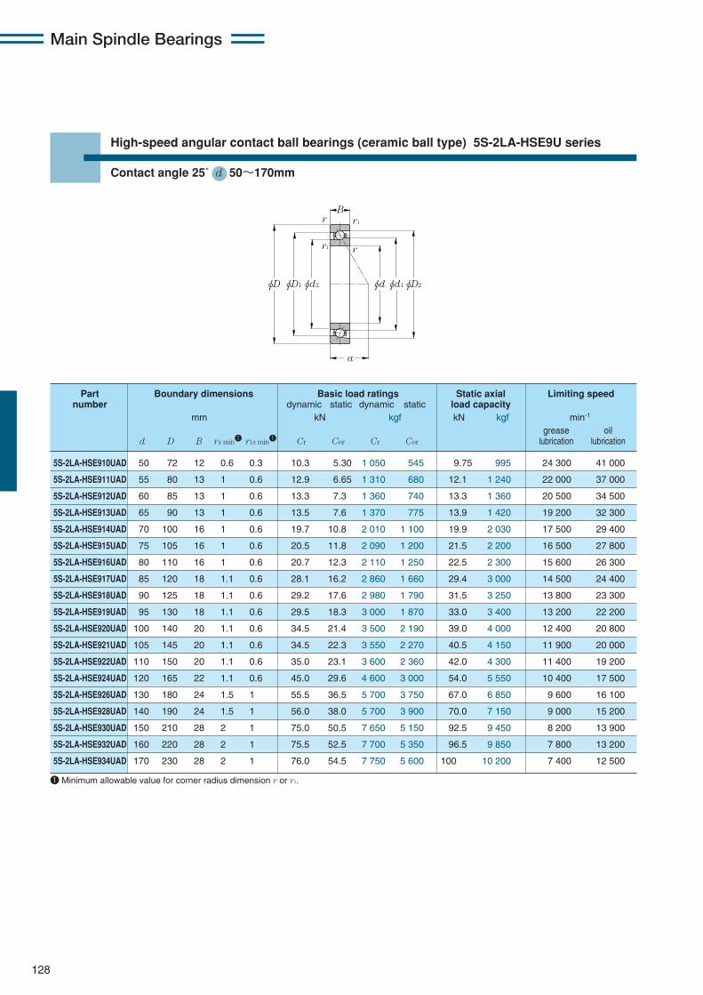
Main Spindle Bearings
φD φD1 φD2φd2 φdφd1
B
a
r1
rr1
r
128
High-speed angular contact ball bearings (ceramic ball type) 5S-2LA-HSE9U series
Contact angle 25˚ d 50〜170mm
5S-2LA-HSE910UAD 50 72 12 0.6 0.3 10.3 5.30 1 050 545 9.75 995 24 300 41 000
5S-2LA-HSE911UAD 55 80 13 1 0.6 12.9 6.65 1 310 680 12.1 1 240 22 000 37 000
5S-2LA-HSE912UAD 60 85 13 1 0.6 13.3 7.3 1 360 740 13.3 1 360 20 500 34 500
5S-2LA-HSE913UAD 65 90 13 1 0.6 13.5 7.6 1 370 775 13.9 1 420 19 200 32 300
5S-2LA-HSE914UAD 70 100 16 1 0.6 19.7 10.8 2 010 1 100 19.9 2 030 17 500 29 400
5S-2LA-HSE915UAD 75 105 16 1 0.6 20.5 11.8 2 090 1 200 21.5 2 200 16 500 27 800
5S-2LA-HSE916UAD 80 110 16 1 0.6 20.7 12.3 2 110 1 250 22.5 2 300 15 600 26 300
5S-2LA-HSE917UAD 85 120 18 1.1 0.6 28.1 16.2 2 860 1 660 29.4 3 000 14 500 24 400
5S-2LA-HSE918UAD 90 125 18 1.1 0.6 29.2 17.6 2 980 1 790 31.5 3 250 13 800 23 300
5S-2LA-HSE919UAD 95 130 18 1.1 0.6 29.5 18.3 3 000 1 870 33.0 3 400 13 200 22 200
5S-2LA-HSE920UAD 100 140 20 1.1 0.6 34.5 21.4 3 500 2 190 39.0 4 000 12 400 20 800
5S-2LA-HSE921UAD 105 145 20 1.1 0.6 34.5 22.3 3 550 2 270 40.5 4 150 11 900 20 000
5S-2LA-HSE922UAD 110 150 20 1.1 0.6 35.0 23.1 3 600 2 360 42.0 4 300 11 400 19 200
5S-2LA-HSE924UAD 120 165 22 1.1 0.6 45.0 29.6 4 600 3 000 54.0 5 550 10 400 17 500
5S-2LA-HSE926UAD 130 180 24 1.5 1 55.5 36.5 5 700 3 750 67.0 6 850 9 600 16 100
5S-2LA-HSE928UAD 140 190 24 1.5 1 56.0 38.0 5 700 3 900 70.0 7 150 9 000 15 200
5S-2LA-HSE930UAD 150 210 28 2 1 75.0 50.5 7 650 5 150 92.5 9 450 8 200 13 900
5S-2LA-HSE932UAD 160 220 28 2 1 75.5 52.5 7 700 5 350 96.5 9 850 7 800 13 200
5S-2LA-HSE934UAD 170 230 28 2 1 76.0 54.5 7 750 5 600 100 10 200 7 400 12 500
Part Boundary dimensions Basic load ratings Static axial Limiting speednumber dynamic static dynamic static load capacity
mm kN kgf kN kgf min-1
grease oild D B rs min1 r1s min1 Cr Cor Cr Cor lubrication lubrication
1 Minimum allowable value for corner radius dimension r or r1.
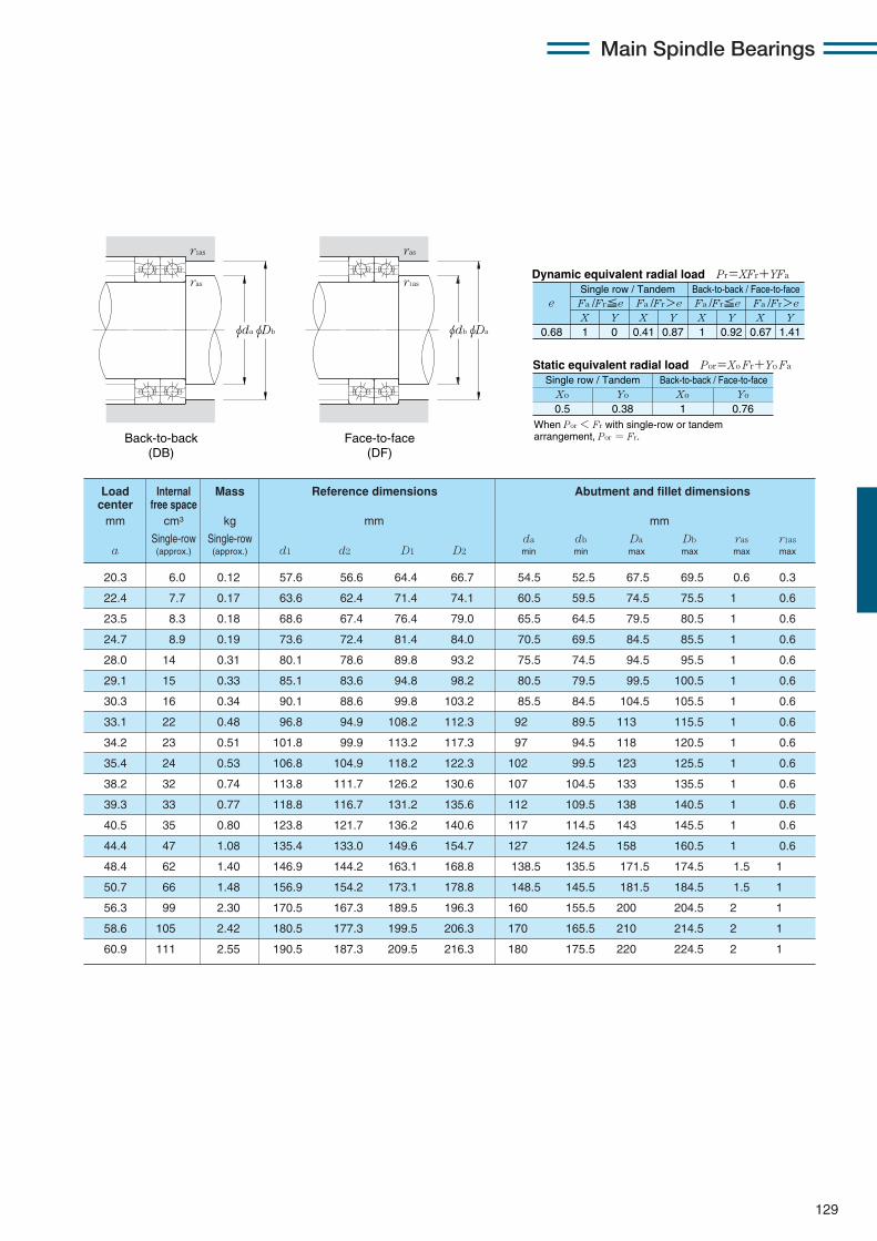
Main Spindle Bearings
129
20.3 6.0 0.12 57.6 56.6 64.4 66.7 54.5 52.5 67.5 69.5 0.6 0.3
22.4 7.7 0.17 63.6 62.4 71.4 74.1 60.5 59.5 74.5 75.5 1 0.6
23.5 8.3 0.18 68.6 67.4 76.4 79.0 65.5 64.5 79.5 80.5 1 0.6
24.7 8.9 0.19 73.6 72.4 81.4 84.0 70.5 69.5 84.5 85.5 1 0.6
28.0 14 0.31 80.1 78.6 89.8 93.2 75.5 74.5 94.5 95.5 1 0.6
29.1 15 0.33 85.1 83.6 94.8 98.2 80.5 79.5 99.5 100.5 1 0.6
30.3 16 0.34 90.1 88.6 99.8 103.2 85.5 84.5 104.5 105.5 1 0.6
33.1 22 0.48 96.8 94.9 108.2 112.3 92 89.5 113 115.5 1 0.6
34.2 23 0.51 101.8 99.9 113.2 117.3 97 94.5 118 120.5 1 0.6
35.4 24 0.53 106.8 104.9 118.2 122.3 102 99.5 123 125.5 1 0.6
38.2 32 0.74 113.8 111.7 126.2 130.6 107 104.5 133 135.5 1 0.6
39.3 33 0.77 118.8 116.7 131.2 135.6 112 109.5 138 140.5 1 0.6
40.5 35 0.80 123.8 121.7 136.2 140.6 117 114.5 143 145.5 1 0.6
44.4 47 1.08 135.4 133.0 149.6 154.7 127 124.5 158 160.5 1 0.6
48.4 62 1.40 146.9 144.2 163.1 168.8 138.5 135.5 171.5 174.5 1.5 1
50.7 66 1.48 156.9 154.2 173.1 178.8 148.5 145.5 181.5 184.5 1.5 1
56.3 99 2.30 170.5 167.3 189.5 196.3 160 155.5 200 204.5 2 1
58.6 105 2.42 180.5 177.3 199.5 206.3 170 165.5 210 214.5 2 1
60.9 111 2.55 190.5 187.3 209.5 216.3 180 175.5 220 224.5 2 1
Load Internal Mass Reference dimensions Abutment and fillet dimensionscenter free spacemm cm3 kg mm mm
Single-row Single-row da db Da Db ras r1asa (approx.) (approx.) d1 d2 D1 D2 min min max max max max
X Y X Y X Y X Y0.68 1 0 0.41 0.87 1 0.92 0.67 1.41
Fa /Fr≦e Fa /Fr>e Fa /Fr≦e Fa /Fr>ee
Static equivalent radial load Por=Xo Fr+Yo Fa
When Por < Fr with single-row or tandem arrangement, Por = Fr.
Xo Yo Xo Yo
0.5 0.38 1 0.76
Dynamic equivalent radial load Pr=XFr+YFa
Single row / Tandem Back-to-back / Face-to-face
Single row / Tandem Back-to-back / Face-to-face
φDbφda
r1as
ras
φDaφdb
r1as
ras
Back-to-back (DB)
Face-to-face (DF)

Main Spindle Bearings
130
High-speed angular contact ball bearings (ceramic ball type) 5S-2LA-HSE0 series
Contact angle 15˚ d 50〜170mm
5S-2LA-HSE010C 50 80 16 1 0.6 15.9 7.90 1 620 805 10.5 1 070 7.2 24 000 39 800
5S-2LA-HSE011C 55 90 18 1.1 0.6 17.3 9.40 1 760 960 12.5 1 280 7.4 21 500 35 700
5S-2LA-HSE012C 60 95 18 1.1 0.6 18.1 10.4 1 850 1 060 13.9 1 420 7.4 20 100 33 400
5S-2LA-HSE013C 65 100 18 1.1 0.6 18.4 10.9 1 870 1 120 14.6 1 490 7.5 18 900 31 400
5S-2LA-HSE014C 70 110 20 1.1 0.6 22.5 13.8 2 290 1 410 18.4 1 880 7.5 17 300 28 700
5S-2LA-HSE015C 75 115 20 1.1 0.6 23.9 15.5 2 440 1 590 20.8 2 120 7.5 16 400 27 200
5S-2LA-HSE016C 80 125 22 1.1 0.6 27.4 17.8 2 790 1 820 23.8 2 430 7.5 15 200 25 200
5S-2LA-HSE017C 85 130 22 1.1 0.6 27.7 18.6 2 830 1 900 24.9 2 540 7.6 14 500 24 100
5S-2LA-HSE018C 90 140 24 1.5 1 32.0 21.8 3 300 2 220 29.2 2 970 7.6 13 600 22 500
5S-2LA-HSE019C 95 145 24 1.5 1 32.5 22.7 3 300 2 310 30.5 3 100 7.6 13 000 21 600
5S-2LA-HSE020C 100 150 24 1.5 1 33.5 24.4 3 450 2 480 32.5 3 350 7.6 12 500 20 700
5S-2LA-HSE021C 105 160 26 2 1 38.5 28.2 3 950 2 880 38.0 3 850 7.6 11 800 19 500
5S-2LA-HSE022C 110 170 28 2 1 48.0 34.0 4 900 3 500 45.5 4 650 7.6 11 100 18 500
5S-2LA-HSE024C 120 180 28 2 1 48.0 35.5 4 900 3 650 47.5 4 850 7.6 10 400 17 200
5S-2LA-HSE026C 130 200 33 2 1 69.0 49.5 7 050 5 000 66.0 6 700 7.5 9 500 15 700
5S-2LA-HSE028C 140 210 33 2 1 71.5 53.5 7 300 5 450 71.5 7 300 7.6 8 900 14 800
5S-2LA-HSE030C 150 225 35 2.1 1.1 73.5 57.5 7 500 5 850 77.0 7 850 7.6 8 300 13 800
5S-2LA-HSE032C 160 240 38 2.1 1.1 86.0 67.0 8 800 6 850 90.0 9 150 7.6 7 800 12 900
5S-2LA-HSE034C 170 260 42 2.1 1.1 99.0 77.0 10 100 7 850 103 10 500 7.6 7 300 12 000
Part Boundary dimensions Basic load ratings Static axial Factor Limiting speednumber dynamic static dynamic static load capacity
mm kN kgf kN kgf min-1
grease oild D B rs min1 r1s min1 Cr Cor Cr Cor fo lubrication lubrication
φD φD1 φD2φd2 φdφd1
B
a
r1
rr1
r
1 Minimum allowable value for corner radius dimension r or r1.
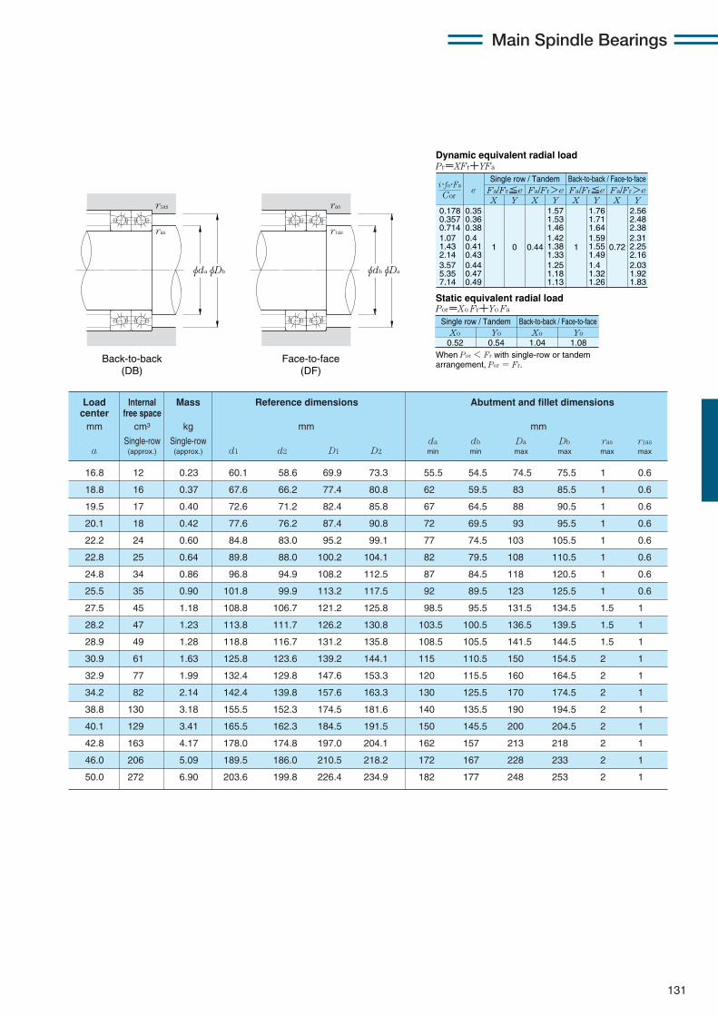
Main Spindle Bearings
131
16.8 12 0.23 60.1 58.6 69.9 73.3 55.5 54.5 74.5 75.5 1 0.6
18.8 16 0.37 67.6 66.2 77.4 80.8 62 59.5 83 85.5 1 0.6
19.5 17 0.40 72.6 71.2 82.4 85.8 67 64.5 88 90.5 1 0.6
20.1 18 0.42 77.6 76.2 87.4 90.8 72 69.5 93 95.5 1 0.6
22.2 24 0.60 84.8 83.0 95.2 99.1 77 74.5 103 105.5 1 0.6
22.8 25 0.64 89.8 88.0 100.2 104.1 82 79.5 108 110.5 1 0.6
24.8 34 0.86 96.8 94.9 108.2 112.5 87 84.5 118 120.5 1 0.6
25.5 35 0.90 101.8 99.9 113.2 117.5 92 89.5 123 125.5 1 0.6
27.5 45 1.18 108.8 106.7 121.2 125.8 98.5 95.5 131.5 134.5 1.5 1
28.2 47 1.23 113.8 111.7 126.2 130.8 103.5 100.5 136.5 139.5 1.5 1
28.9 49 1.28 118.8 116.7 131.2 135.8 108.5 105.5 141.5 144.5 1.5 1
30.9 61 1.63 125.8 123.6 139.2 144.1 115 110.5 150 154.5 2 1
32.9 77 1.99 132.4 129.8 147.6 153.3 120 115.5 160 164.5 2 1
34.2 82 2.14 142.4 139.8 157.6 163.3 130 125.5 170 174.5 2 1
38.8 130 3.18 155.5 152.3 174.5 181.6 140 135.5 190 194.5 2 1
40.1 129 3.41 165.5 162.3 184.5 191.5 150 145.5 200 204.5 2 1
42.8 163 4.17 178.0 174.8 197.0 204.1 162 157 213 218 2 1
46.0 206 5.09 189.5 186.0 210.5 218.2 172 167 228 233 2 1
50.0 272 6.90 203.6 199.8 226.4 234.9 182 177 248 253 2 1
Load Internal Mass Reference dimensions Abutment and fillet dimensionscenter free spacemm cm3 kg mm mm
Single-row Single-row da db Da Db ras r1asa (approx.) (approx.) d1 d2 D1 D2 min min max max max max
0.178 0.357 0.714 1.07 1.43 2.14 3.57 5.35 7.14
eX Y
Dynamic equivalent radial loadPr=XFr+YFa
Static equivalent radial loadPor=Xo Fr+Yo Fa
Fa/Fr≦e Fa/Fr>e Fa/Fr≦e Fa/Fr>eX Y X Y X Y
0.35 0.36 0.38 0.4 0.41 0.43 0.44 0.47 0.49
1 0 0.44
1.57 1.53 1.46 1.42 1.38 1.33 1.25 1.18 1.13
1
1.76 1.71 1.64 1.59 1.55 1.49 1.4 1.32 1.26
0.72
2.56 2.48 2.38 2.31 2.25 2.16 2.03 1.92 1.83
When Por < Fr with single-row or tandem arrangement, Por = Fr.
Xo0.52
Yo Xo Yo0.54 1.04 1.08
Cor
i・fo・Fa
Single row / Tandem Back-to-back / Face-to-face
Single row / Tandem Back-to-back / Face-to-face
φDbφda
r1as
ras
φDaφdb
r1as
ras
Back-to-back (DB)
Face-to-face (DF)

Main Spindle Bearings
132
High-speed angular contact ball bearings (ceramic ball type) 5S-2LA-HSE0 series
Contact angle 20˚ d 50〜170mm
φD φD1 φD2φd2 φdφd1
B
a
r1
rr1
r
5S-2LA-HSE010 50 80 16 1 0.6 15.5 7.75 1 580 790 12.1 1 230 26 500 43 300
5S-2LA-HSE011 55 90 18 1.1 0.6 16.8 9.20 1 720 935 14.4 1 460 23 700 38 800
5S-2LA-HSE012 60 95 18 1.1 0.6 17.6 10.2 1 800 1 040 15.9 1 620 22 200 36 300
5S-2LA-HSE013 65 100 18 1.1 0.6 17.9 10.7 1 830 1 090 16.7 1 710 20 800 34 100
5S-2LA-HSE014 70 110 20 1.1 0.6 21.9 13.5 2 230 1 370 21.1 2 150 19 100 31 200
5S-2LA-HSE015 75 115 20 1.1 0.6 23.3 15.2 2 380 1 550 23.8 2 420 18 100 29 600
5S-2LA-HSE016 80 125 22 1.1 0.6 26.7 17.4 2 720 1 770 27.2 2 780 16 800 27 400
5S-2LA-HSE017 85 130 22 1.1 0.6 27.0 18.1 2 760 1 850 28.4 2 900 16 000 26 200
5S-2LA-HSE018 90 140 24 1.5 1 31.5 21.3 3 200 2 170 33.5 3 400 15 000 24 500
5S-2LA-HSE019 95 145 24 1.5 1 31.5 22.1 3 250 2 260 34.5 3 550 14 300 23 400
5S-2LA-HSE020 100 150 24 1.5 1 33.0 23.8 3 350 2 420 37.5 3 800 13 800 22 500
5S-2LA-HSE021 105 160 26 2 1 37.5 27.5 3 850 2 810 43.0 4 400 13 000 21 200
5S-2LA-HSE022 110 170 28 2 1 46.5 33.5 4 750 3 400 52.0 5 300 12 300 20 100
5S-2LA-HSE024 120 180 28 2 1 47.0 35.0 4 800 3 550 54.5 5 550 11 500 18 700
5S-2LA-HSE026 130 200 33 2 1 67.5 48.0 6 900 4 900 75.5 7 700 10 400 17 000
5S-2LA-HSE028 140 210 33 2 1 70.0 52.0 7 100 5 300 81.5 8 300 9 800 16 100
5S-2LA-HSE030 150 225 35 2.1 1.1 72.0 56.0 7 300 5 700 88.0 8 950 9 200 15 000
5S-2LA-HSE032 160 240 38 2.1 1.1 84.0 65.5 8 550 6 700 103 10 500 8 600 14 100
5S-2LA-HSE034 170 260 42 2.1 1.1 96.5 75.0 9 850 7 650 118 12 000 8 000 13 100
Part Boundary dimensions Basic load ratings Static axial Limiting speednumber dynamic static dynamic static load capacity
mm kN kgf kN kgf min-1
grease oild D B rs min1 r1s min1 Cr Cor Cr Cor lubrication lubrication
1 Minimum allowable value for corner radius dimension r or r1.

Main Spindle Bearings
133
19.9 12 0.23 60.1 58.6 69.9 73.2 55.5 54.5 74.5 75.5 1 0.6
22.3 16 0.37 67.6 66.2 77.4 80.8 62 59.5 83 85.5 1 0.6
23.2 17 0.40 72.6 71.2 82.4 85.8 67 64.5 88 90.5 1 0.6
24.1 18 0.42 77.6 76.2 87.4 90.8 72 69.5 93 95.5 1 0.6
26.5 24 0.60 84.8 83.0 95.2 99.1 77 74.5 103 105.5 1 0.6
27.4 25 0.64 89.8 88.0 100.2 104.1 82 79.5 108 110.5 1 0.6
29.8 34 0.86 96.8 94.9 108.2 112.5 87 84.5 118 120.5 1 0.6
30.7 35 0.90 101.8 99.9 113.2 117.4 92 89.5 123 125.5 1 0.6
33.1 45 1.18 108.8 106.7 121.2 125.8 98.5 95.5 131.5 134.5 1.5 1
34.0 47 1.23 113.8 111.7 126.2 130.8 103.5 100.5 136.5 139.5 1.5 1
34.9 49 1.28 118.8 116.7 131.2 135.8 108.5 105.5 141.5 144.5 1.5 1
37.3 61 1.63 125.8 123.6 139.2 144.1 115 110.5 150 154.5 2 1
39.7 77 1.99 132.4 129.8 147.6 153.2 120 115.5 160 164.5 2 1
41.5 82 2.14 142.4 139.8 157.6 163.2 130 125.5 170 174.5 2 1
46.8 130 3.18 155.5 152.3 174.5 181.5 140 135.5 190 194.5 2 1
48.6 129 3.41 165.5 162.3 184.5 191.5 150 145.5 200 204.5 2 1
51.9 163 4.17 178.0 174.8 197.0 204.0 162 157 213 218 2 1
55.7 206 5.09 189.5 186.0 210.5 218.2 172 167 228 233 2 1
60.4 272 6.90 203.6 199.8 226.4 234.9 182 177 248 253 2 1
Load Internal Mass Reference dimensions Abutment and fillet dimensionscenter free spacemm cm3 kg mm mm
Single-row Single-row da db Da Db ras r1asa (approx.) (approx.) d1 d2 D1 D2 min min max max max max
X Y X Y X Y X Y0.57 1 0 0.43 1 1 1.09 0.7 1.63
Fa /Fr≦e Fa /Fr>e Fa /Fr≦e Fa /Fr>ee
Static equivalent radial load Por=Xo Fr+Yo Fa
When Por < Fr with single-row or tandem arrangement, Por = Fr.
Xo Yo Xo Yo
0.5 0.42 1 0.84
Dynamic equivalent radial load Pr=XFr+YFa
Single row / Tandem Back-to-back / Face-to-face
Single row / Tandem Back-to-back / Face-to-face
φDbφda
r1as
ras
φDaφdb
r1as
ras
Back-to-back (DB)
Face-to-face (DF)
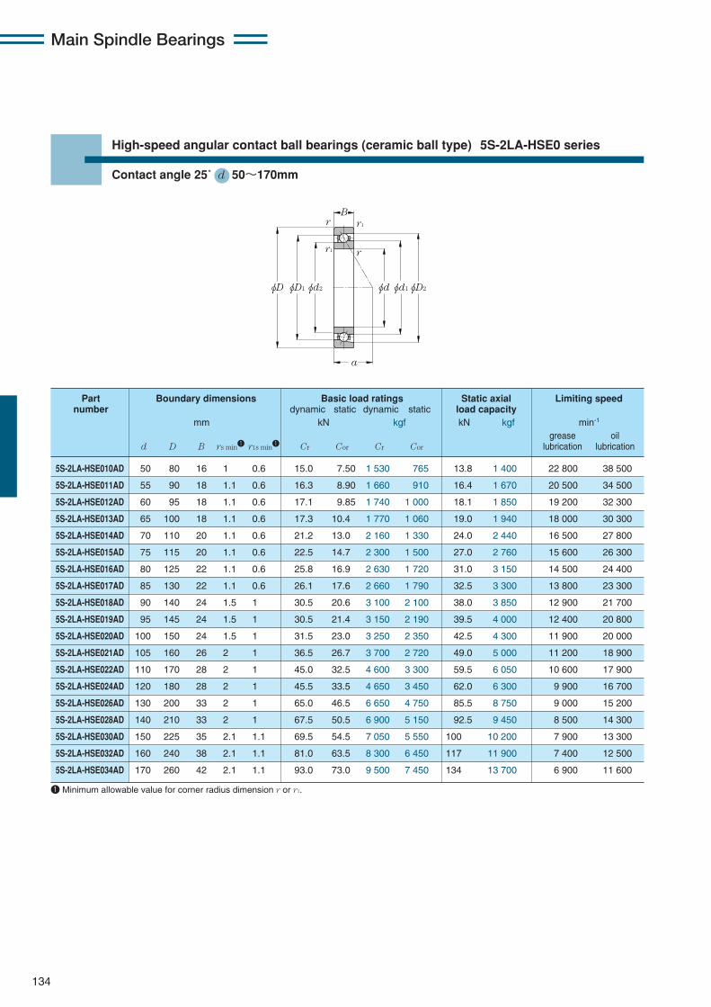
Main Spindle Bearings
134
High-speed angular contact ball bearings (ceramic ball type) 5S-2LA-HSE0 series
Contact angle 25˚ d 50〜170mm
φD φD1 φD2φd2 φdφd1
B
a
r1
rr1
r
5S-2LA-HSE010AD 50 80 16 1 0.6 15.0 7.50 1 530 765 13.8 1 400 22 800 38 500
5S-2LA-HSE011AD 55 90 18 1.1 0.6 16.3 8.90 1 660 910 16.4 1 670 20 500 34 500
5S-2LA-HSE012AD 60 95 18 1.1 0.6 17.1 9.85 1 740 1 000 18.1 1 850 19 200 32 300
5S-2LA-HSE013AD 65 100 18 1.1 0.6 17.3 10.4 1 770 1 060 19.0 1 940 18 000 30 300
5S-2LA-HSE014AD 70 110 20 1.1 0.6 21.2 13.0 2 160 1 330 24.0 2 440 16 500 27 800
5S-2LA-HSE015AD 75 115 20 1.1 0.6 22.5 14.7 2 300 1 500 27.0 2 760 15 600 26 300
5S-2LA-HSE016AD 80 125 22 1.1 0.6 25.8 16.9 2 630 1 720 31.0 3 150 14 500 24 400
5S-2LA-HSE017AD 85 130 22 1.1 0.6 26.1 17.6 2 660 1 790 32.5 3 300 13 800 23 300
5S-2LA-HSE018AD 90 140 24 1.5 1 30.5 20.6 3 100 2 100 38.0 3 850 12 900 21 700
5S-2LA-HSE019AD 95 145 24 1.5 1 30.5 21.4 3 150 2 190 39.5 4 000 12 400 20 800
5S-2LA-HSE020AD 100 150 24 1.5 1 31.5 23.0 3 250 2 350 42.5 4 300 11 900 20 000
5S-2LA-HSE021AD 105 160 26 2 1 36.5 26.7 3 700 2 720 49.0 5 000 11 200 18 900
5S-2LA-HSE022AD 110 170 28 2 1 45.0 32.5 4 600 3 300 59.5 6 050 10 600 17 900
5S-2LA-HSE024AD 120 180 28 2 1 45.5 33.5 4 650 3 450 62.0 6 300 9 900 16 700
5S-2LA-HSE026AD 130 200 33 2 1 65.0 46.5 6 650 4 750 85.5 8 750 9 000 15 200
5S-2LA-HSE028AD 140 210 33 2 1 67.5 50.5 6 900 5 150 92.5 9 450 8 500 14 300
5S-2LA-HSE030AD 150 225 35 2.1 1.1 69.5 54.5 7 050 5 550 100 10 200 7 900 13 300
5S-2LA-HSE032AD 160 240 38 2.1 1.1 81.0 63.5 8 300 6 450 117 11 900 7 400 12 500
5S-2LA-HSE034AD 170 260 42 2.1 1.1 93.0 73.0 9 500 7 450 134 13 700 6 900 11 600
Part Boundary dimensions Basic load ratings Static axial Limiting speednumber dynamic static dynamic static load capacity
mm kN kgf kN kgf min-1
grease oild D B rs min1 r1s min1 Cr Cor Cr Cor lubrication lubrication
1 Minimum allowable value for corner radius dimension r or r1.

Main Spindle Bearings
135
23.3 12 0.23 60.1 58.6 69.9 73.2 55.5 54.5 74.5 75.5 1 0.6
26.1 16 0.37 67.6 66.2 77.4 80.8 62 59.5 83 85.5 1 0.6
27.2 17 0.40 72.6 71.2 82.4 85.8 67 64.5 88 90.5 1 0.6
28.4 18 0.40 77.6 76.2 87.4 90.8 72 69.5 93 95.5 1 0.6
31.1 24 0.60 84.8 83.0 95.2 99.1 77 74.5 103 105.5 1 0.6
32.3 25 0.64 89.8 88.0 100.2 104.1 82 79.5 108 110.5 1 0.6
35.1 34 0.86 96.8 94.9 108.2 112.5 87 84.5 118 120.5 1 0.6
36.2 35 0.90 101.8 99.9 113.2 117.4 92 89.5 123 125.5 1 0.6
39.0 45 1.18 108.8 106.7 121.2 125.8 98.5 95.5 131.5 134.5 1.5 1
40.2 47 1.23 113.8 111.7 126.2 130.8 103.5 100.5 136.5 139.5 1.5 1
41.3 49 1.28 118.8 116.7 131.2 135.8 108.5 105.5 141.5 144.5 1.5 1
44.1 61 1.63 125.8 123.6 139.2 144.1 115 110.5 150 154.5 2 1
46.9 77 1.99 132.4 129.8 147.6 153.2 120 115.5 160 164.5 2 1
49.2 82 2.14 142.4 139.8 157.6 163.2 130 125.5 170 174.5 2 1
55.3 130 3.18 155.5 152.3 174.5 181.5 140 135.5 190 194.5 2 1
57.6 129 3.41 165.5 162.3 184.5 191.5 150 145.5 200 204.5 2 1
61.5 163 4.17 178.0 174.8 197.0 204.0 162 157 213 218 2 1
66.0 206 5.09 189.5 186.0 210.5 218.2 172 167 228 233 2 1
71.5 272 6.90 203.6 199.8 226.4 234.9 182 177 248 253 2 1
Load Internal Mass Reference dimensions Abutment and fillet dimensionscenter free spacemm cm3 kg mm mm
Single-row Single-row da db Da Db ras r1asa (approx.) (approx.) d1 d2 D1 D2 min min max max max max
X Y X Y X Y X Y0.68 1 0 0.41 0.87 1 0.92 0.67 1.41
Fa /Fr≦e Fa /Fr>e Fa /Fr≦e Fa /Fr>ee
Static equivalent radial load Por=Xo Fr+Yo Fa
When Por < Fr with single-row or tandem arrangement, Por = Fr.
Xo Yo Xo Yo
0.5 0.38 1 0.76
Dynamic equivalent radial load Pr=XFr+YFa
Single row / Tandem Back-to-back / Face-to-face
Single row / Tandem Back-to-back / Face-to-face
φDbφda
r1as
ras
φDaφdb
r1as
ras
Back-to-back (DB)
Face-to-face (DF)

Main Spindle Bearings
136
Super high-speed angular contact ball bearings 5S-2LA-HSF0 series
Contact angle 25˚ d 50〜100mm
φDφD1 φD2φd1φd2 φd
B
a
r
r1
r1
r
5S-2LA-HSF010AD 50 80 16 1 0.6 10.1 6.20 1 030 635 11.4 1 170 50 000
5S-2LA-HSF011AD 55 90 18 1.1 0.6 12.6 7.80 1 280 800 14.4 1 470 44 800
5S-2LA-HSF012AD 60 95 18 1.1 0.6 12.9 8.45 1 320 860 15.5 1 580 41 900
5S-2LA-HSF013AD 65 100 18 1.1 0.6 13.3 9.05 1 360 925 16.7 1 700 39 400
5S-2LA-HSF014AD 70 110 20 1.1 0.6 16.2 11.1 1 650 1 130 20.4 2 080 36 100
5S-2LA-HSF015AD 75 115 20 1.1 0.6 16.7 11.9 1 700 1 210 21.8 2 220 34 200
5S-2LA-HSF016AD 80 125 22 1.1 0.6 19.9 14.2 2 030 1 440 26.0 2 660 31 700
5S-2LA-HSF017AD 85 130 22 1.1 0.6 20.1 14.7 2 050 1 500 27.0 2 750 30 200
5S-2LA-HSF018AD 90 140 24 1.5 1 24.5 18.2 2 500 1 860 33.5 3 400 28 300
5S-2LA-HSF019AD 95 145 24 1.5 1 24.7 18.8 2 520 1 920 34.5 3 550 27 100
5S-2LA-HSF020AD 100 150 24 1.5 1 25.3 20.0 2 580 2 040 37.0 3 750 26 000
Part Boundary dimensions Basic load ratings Static axial Limitingnumber dynamic static dynamic static load capacity speed
mm kN kgf kN kgf min-1
oild D B rs min1 r1s min1 Cr Cor Cr Cor lubrication
1 Minimum allowable value for corner radius dimension r or r1.
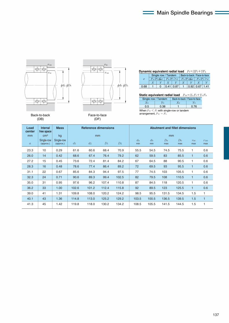
Main Spindle Bearings
137
X Y X Y X Y X Y0.68 1 0 0.41 0.87 1 0.92 0.67 1.41
Fa /Fr≦e Fa /Fr>e Fa /Fr≦e Fa /Fr>ee
Static equivalent radial load Por=Xo Fr+Yo Fa
When Por < Fr with single-row or tandem arrangement, Por = Fr.
Xo Yo Xo Yo
0.5 0.38 1 0.76
Dynamic equivalent radial load Pr=XFr+YFa
Single row / Tandem Back-to-back / Face-to-face
Single row / Tandem Back-to-back / Face-to-face
23.3 10 0.29 61.6 60.6 68.4 70.9 55.5 54.5 74.5 75.5 1 0.6
26.0 14 0.42 68.6 67.4 76.4 79.2 62 59.5 83 85.5 1 0.6
27.2 15 0.45 73.6 72.4 81.4 84.2 67 64.5 88 90.5 1 0.6
28.3 16 0.48 78.6 77.4 86.4 89.2 72 69.5 93 95.5 1 0.6
31.1 22 0.67 85.6 84.3 94.4 97.5 77 74.5 103 105.5 1 0.6
32.3 24 0.71 90.6 89.3 99.4 102.5 82 79.5 108 110.5 1 0.6
35.0 31 0.95 97.6 96.2 107.4 110.8 87 84.5 118 120.5 1 0.6
36.2 33 1.00 102.6 101.2 112.4 115.8 92 89.5 123 125.5 1 0.6
39.0 41 1.31 109.8 108.0 120.2 124.2 98.5 95.5 131.5 134.5 1.5 1
40.1 43 1.36 114.8 113.0 125.2 129.2 103.5 100.5 136.5 139.5 1.5 1
41.3 45 1.42 119.8 118.0 130.2 134.2 108.5 105.5 141.5 144.5 1.5 1
Load Internal Mass Reference dimensions Abutment and fillet dimensionscenter free spacemm cm3 kg mm mm
Single-row Single-row da db Da Db ras r1asa (approx.) (approx.) d1 d2 D1 D2 min min max max max max
Back-to-back (DB)
Face-to-face (DF)
φDbφda
r1as
ras
φDaφdb
ras
r1as

Main Spindle Bearings
138
Eco-friendly angular contact ball bearings (ceramic ball type) 5S-2LA-HSL9U series
Contact angle 20˚ d 50〜130mm
φD φdφd1φD2
B
a
r
rr1
r1
5S-2LA-HSL910U 50 72 12 0.6 0.3 10.7 5.50 1 090 560 8.55 875 46 100
5S-2LA-HSL911U 55 80 13 1 0.6 13.3 6.85 1 360 700 10.6 1 090 41 700
5S-2LA-HSL912U 60 85 13 1 0.6 13.8 7.50 1 410 765 11.6 1 190 38 800
5S-2LA-HSL913U 65 90 13 1 0.6 13.9 7.85 1 420 800 12.2 1 250 36 300
5S-2LA-HSL914U 70 100 16 1 0.6 20.4 11.2 2 080 1 140 17.4 1 780 33 100
5S-2LA-HSL915U 75 105 16 1 0.6 21.2 12.2 2 160 1 240 19.0 1 940 31 300
5S-2LA-HSL916U 80 110 16 1 0.6 21.4 12.7 2 190 1 290 19.8 2 020 29 600
5S-2LA-HSL917U 85 120 18 1.1 0.6 29.1 16.8 2 960 1 710 26.1 2 670 27 400
5S-2LA-HSL918U 90 125 18 1.1 0.6 30.0 18.1 3 100 1 850 28.3 2 890 26 200
5S-2LA-HSL919U 95 130 18 1.1 0.6 30.5 18.9 3 100 1 930 29.4 3 000 25 000
5S-2LA-HSL920U 100 140 20 1.1 0.6 35.5 22.1 3 600 2 260 34.0 3 500 23 400
5S-2LA-HSL921U 105 145 20 1.1 0.6 36.0 23.0 3 650 2 350 35.5 3 650 22 500
5S-2LA-HSL922U 110 150 20 1.1 0.6 36.5 23.9 3 700 2 430 37.0 3 800 21 600
5S-2LA-HSL924U 120 165 22 1.1 0.6 46.5 30.5 4 750 3 100 47.5 4 850 19 700
5S-2LA-HSL926U 130 180 24 1.5 1 57.5 38.0 5 850 3 850 58.5 6 000 18 100
Part Boundary dimensions Basic load ratings Static axial Limitingnumber dynamic static dynamic static load capacity speed
mm kN kgf kN kgf min-1
oild D B rs min1 r1s min1 Cr Cor Cr Cor lubrication
1 Minimum allowable value for corner radius dimension r or r1.2 For the details of spacer dimensions, please contact NTN Engineering.

Main Spindle Bearings
139
X Y X Y X Y X Y0.57 1 0 0.43 1 1 1.09 0.7 1.63
Fa /Fr≦e Fa /Fr>e Fa /Fr≦e Fa /Fr>ee
Static equivalent radial load Por=Xo Fr+Yo Fa
When Por < Fr with single-row or tandem arrangement, Por = Fr.
Xo Yo Xo Yo
0.5 0.42 1 0.84
Dynamic equivalent radial load Pr=XFr+YFa
Single row / Tandem Back-to-back / Face-to-face
Single row / Tandem Back-to-back / Face-to-face
17.2 0.11 57.6 66.8 54.5 69.5 0.3 8.5 5S-2LA-HSL910U
18.9 0.16 63.6 74.1 60.5 75.5 0.6 8.5 5S-2LA-HSL911U
19.8 0.17 68.6 79.1 65.5 80.5 0.6 8.5 5S-2LA-HSL912U
20.7 0.17 73.6 84.0 70.5 85.5 0.6 8.5 5S-2LA-HSL913U
23.6 0.29 80.1 93.2 75.5 95.5 0.6 8.5 5S-2LA-HSL914U
24.5 0.31 85.1 98.2 80.5 100.5 0.6 9 5S-2LA-HSL915U
25.4 0.32 90.1 103.2 85.5 105.5 0.6 9 5S-2LA-HSL916U
27.8 0.45 96.8 112.3 92 115.5 0.6 9 5S-2LA-HSL917U
28.7 0.48 101.8 117.3 97 120.5 0.6 9 5S-2LA-HSL918U
29.6 0.50 106.8 122.3 102 125.5 0.6 9 5S-2LA-HSL919U
32.0 0.69 113.8 130.6 107 135.5 0.6 9 5S-2LA-HSL920U
32.9 0.72 118.8 135.6 112 140.5 0.6 9 5S-2LA-HSL921U
33.8 0.75 123.8 140.6 117 145.5 0.6 9 5S-2LA-HSL922U
37.1 1.01 135.4 154.7 127 160.5 0.6 9 5S-2LA-HSL924U
40.4 1.32 146.9 168.9 138.5 174.5 1 9 5S-2LA-HSL926U
Load Mass Reference Abutment and fillet dimensions Partcenter dimensions numbermm kg mm mm
Single-row da Db r1as l 2
a (approx.) d1 D2 min max max min
φda φDb
r1as
l
ras
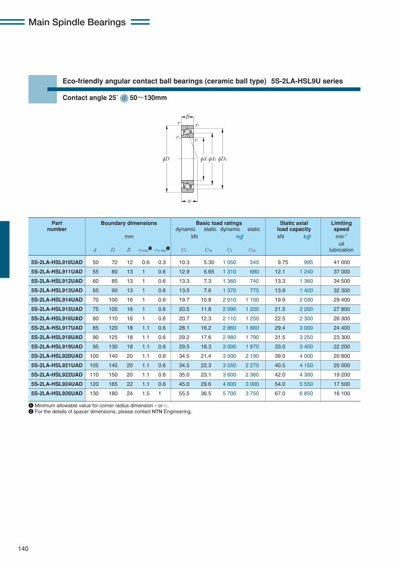
Main Spindle Bearings
140
Eco-friendly angular contact ball bearings (ceramic ball type) 5S-2LA-HSL9U series
Contact angle 25˚ d 50〜130mm
φD φdφd1φD2
B
a
r
rr1
r1
5S-2LA-HSL910UAD 50 72 12 0.6 0.3 10.3 5.30 1 050 545 9.75 995 41 000
5S-2LA-HSL911UAD 55 80 13 1 0.6 12.9 6.65 1 310 680 12.1 1 240 37 000
5S-2LA-HSL912UAD 60 85 13 1 0.6 13.3 7.3 1 360 740 13.3 1 360 34 500
5S-2LA-HSL913UAD 65 90 13 1 0.6 13.5 7.6 1 370 775 13.9 1 420 32 300
5S-2LA-HSL914UAD 70 100 16 1 0.6 19.7 10.8 2 010 1 100 19.9 2 030 29 400
5S-2LA-HSL915UAD 75 105 16 1 0.6 20.5 11.8 2 090 1 200 21.5 2 200 27 800
5S-2LA-HSL916UAD 80 110 16 1 0.6 20.7 12.3 2 110 1 250 22.5 2 300 26 300
5S-2LA-HSL917UAD 85 120 18 1.1 0.6 28.1 16.2 2 860 1 660 29.4 3 000 24 400
5S-2LA-HSL918UAD 90 125 18 1.1 0.6 29.2 17.6 2 980 1 790 31.5 3 250 23 300
5S-2LA-HSL919UAD 95 130 18 1.1 0.6 29.5 18.3 3 000 1 870 33.0 3 400 22 200
5S-2LA-HSL920UAD 100 140 20 1.1 0.6 34.5 21.4 3 500 2 190 39.0 4 000 20 800
5S-2LA-HSL921UAD 105 145 20 1.1 0.6 34.5 22.3 3 550 2 270 40.5 4 150 20 000
5S-2LA-HSL922UAD 110 150 20 1.1 0.6 35.0 23.1 3 600 2 360 42.0 4 300 19 200
5S-2LA-HSL924UAD 120 165 22 1.1 0.6 45.0 29.6 4 600 3 000 54.0 5 550 17 500
5S-2LA-HSL926UAD 130 180 24 1.5 1 55.5 36.5 5 700 3 750 67.0 6 850 16 100
Part Boundary dimensions Basic load ratings Static axial Limitingnumber dynamic static dynamic static load capacity speed
mm kN kgf kN kgf min-1
oild D B rs min1 r1s min1 Cr Cor Cr Cor lubrication
1 Minimum allowable value for corner radius dimension r or r1.2 For the details of spacer dimensions, please contact NTN Engineering.
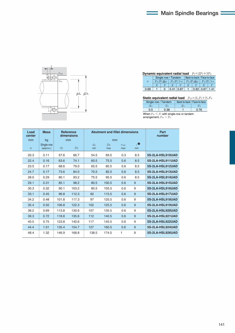
Main Spindle Bearings
141
X Y X Y X Y X Y0.68 1 0 0.41 0.87 1 0.92 0.67 1.41
Fa /Fr≦e Fa /Fr>e Fa /Fr≦e Fa /Fr>ee
Static equivalent radial load Por=Xo Fr+Yo Fa
When Por < Fr with single-row or tandem arrangement, Por = Fr.
Xo Yo Xo Yo
0.5 0.38 1 0.76
Dynamic equivalent radial load Pr=XFr+YFa
Single row / Tandem Back-to-back / Face-to-face
Single row / Tandem Back-to-back / Face-to-face
20.3 0.11 57.6 66.7 54.5 69.5 0.3 8.5 5S-2LA-HSL910UAD
22.4 0.16 63.6 74.1 60.5 75.5 0.6 8.5 5S-2LA-HSL911UAD
23.5 0.17 68.6 79.0 65.5 80.5 0.6 8.5 5S-2LA-HSL912UAD
24.7 0.17 73.6 84.0 70.5 85.5 0.6 8.5 5S-2LA-HSL913UAD
28.0 0.29 80.1 93.2 75.5 95.5 0.6 8.5 5S-2LA-HSL914UAD
29.1 0.31 85.1 98.2 80.5 100.5 0.6 9 5S-2LA-HSL915UAD
30.3 0.32 90.1 103.2 85.5 105.5 0.6 9 5S-2LA-HSL916UAD
33.1 0.45 96.8 112.3 92 115.5 0.6 9 5S-2LA-HSL917UAD
34.2 0.48 101.8 117.3 97 120.5 0.6 9 5S-2LA-HSL918UAD
35.4 0.50 106.8 122.3 102 125.5 0.6 9 5S-2LA-HSL919UAD
38.2 0.69 113.8 130.6 107 135.5 0.6 9 5S-2LA-HSL920UAD
39.3 0.72 118.8 135.6 112 140.5 0.6 9 5S-2LA-HSL921UAD
40.5 0.75 123.8 140.6 117 145.5 0.6 9 5S-2LA-HSL922UAD
44.4 1.01 135.4 154.7 127 160.5 0.6 9 5S-2LA-HSL924UAD
48.4 1.32 146.9 168.8 138.5 174.5 1 9 5S-2LA-HSL926UAD
Load Mass Reference Abutment and fillet dimensions Partcenter dimensions numbermm kg mm mm
Single-row da Db r1as l 2
a (approx.) d1 D2 min max max min
φda φDb
r1as
l
ras
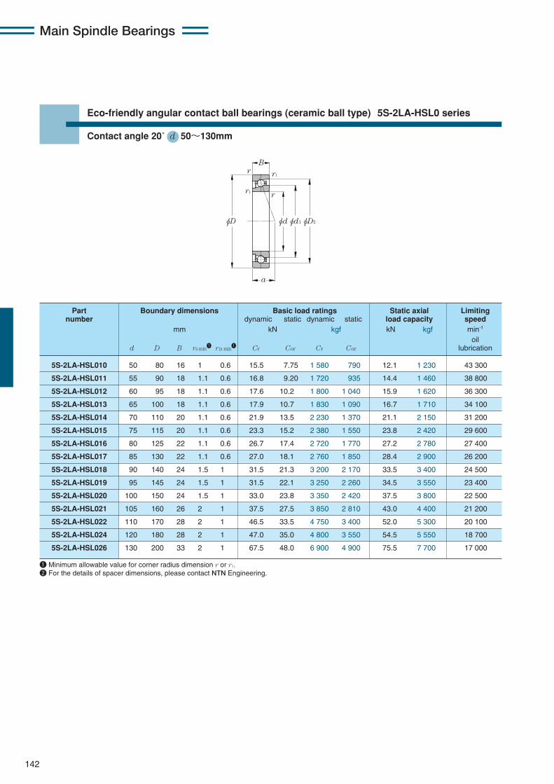
Main Spindle Bearings
142
Eco-friendly angular contact ball bearings (ceramic ball type) 5S-2LA-HSL0 series
Contact angle 20˚ d 50〜130mm
φD φdφd1φD2
B
a
r
rr1
r1
5S-2LA-HSL010 50 80 16 1 0.6 15.5 7.75 1 580 790 12.1 1 230 43 300
5S-2LA-HSL011 55 90 18 1.1 0.6 16.8 9.20 1 720 935 14.4 1 460 38 800
5S-2LA-HSL012 60 95 18 1.1 0.6 17.6 10.2 1 800 1 040 15.9 1 620 36 300
5S-2LA-HSL013 65 100 18 1.1 0.6 17.9 10.7 1 830 1 090 16.7 1 710 34 100
5S-2LA-HSL014 70 110 20 1.1 0.6 21.9 13.5 2 230 1 370 21.1 2 150 31 200
5S-2LA-HSL015 75 115 20 1.1 0.6 23.3 15.2 2 380 1 550 23.8 2 420 29 600
5S-2LA-HSL016 80 125 22 1.1 0.6 26.7 17.4 2 720 1 770 27.2 2 780 27 400
5S-2LA-HSL017 85 130 22 1.1 0.6 27.0 18.1 2 760 1 850 28.4 2 900 26 200
5S-2LA-HSL018 90 140 24 1.5 1 31.5 21.3 3 200 2 170 33.5 3 400 24 500
5S-2LA-HSL019 95 145 24 1.5 1 31.5 22.1 3 250 2 260 34.5 3 550 23 400
5S-2LA-HSL020 100 150 24 1.5 1 33.0 23.8 3 350 2 420 37.5 3 800 22 500
5S-2LA-HSL021 105 160 26 2 1 37.5 27.5 3 850 2 810 43.0 4 400 21 200
5S-2LA-HSL022 110 170 28 2 1 46.5 33.5 4 750 3 400 52.0 5 300 20 100
5S-2LA-HSL024 120 180 28 2 1 47.0 35.0 4 800 3 550 54.5 5 550 18 700
5S-2LA-HSL026 130 200 33 2 1 67.5 48.0 6 900 4 900 75.5 7 700 17 000
Part Boundary dimensions Basic load ratings Static axial Limitingnumber dynamic static dynamic static load capacity speed
mm kN kgf kN kgf min-1
oild D B rs min1 r1s min1 Cr Cor Cr Cor lubrication
1 Minimum allowable value for corner radius dimension r or r1.2 For the details of spacer dimensions, please contact NTN Engineering.
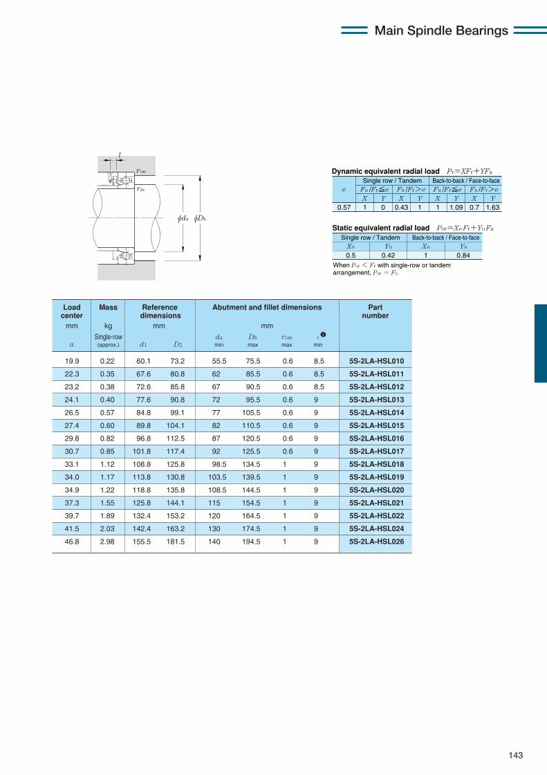
Main Spindle Bearings
143
X Y X Y X Y X Y0.57 1 0 0.43 1 1 1.09 0.7 1.63
Fa /Fr≦e Fa /Fr>e Fa /Fr≦e Fa /Fr>ee
Static equivalent radial load Por=Xo Fr+Yo Fa
When Por < Fr with single-row or tandem arrangement, Por = Fr.
Xo Yo Xo Yo
0.5 0.42 1 0.84
Dynamic equivalent radial load Pr=XFr+YFa
Single row / Tandem Back-to-back / Face-to-face
Single row / Tandem Back-to-back / Face-to-face
19.9 0.22 60.1 73.2 55.5 75.5 0.6 8.5 5S-2LA-HSL010
22.3 0.35 67.6 80.8 62 85.5 0.6 8.5 5S-2LA-HSL011
23.2 0.38 72.6 85.8 67 90.5 0.6 8.5 5S-2LA-HSL012
24.1 0.40 77.6 90.8 72 95.5 0.6 9 5S-2LA-HSL013
26.5 0.57 84.8 99.1 77 105.5 0.6 9 5S-2LA-HSL014
27.4 0.60 89.8 104.1 82 110.5 0.6 9 5S-2LA-HSL015
29.8 0.82 96.8 112.5 87 120.5 0.6 9 5S-2LA-HSL016
30.7 0.85 101.8 117.4 92 125.5 0.6 9 5S-2LA-HSL017
33.1 1.12 108.8 125.8 98.5 134.5 1 9 5S-2LA-HSL018
34.0 1.17 113.8 130.8 103.5 139.5 1 9 5S-2LA-HSL019
34.9 1.22 118.8 135.8 108.5 144.5 1 9 5S-2LA-HSL020
37.3 1.55 125.8 144.1 115 154.5 1 9 5S-2LA-HSL021
39.7 1.89 132.4 153.2 120 164.5 1 9 5S-2LA-HSL022
41.5 2.03 142.4 163.2 130 174.5 1 9 5S-2LA-HSL024
46.8 2.98 155.5 181.5 140 194.5 1 9 5S-2LA-HSL026
Load Mass Reference Abutment and fillet dimensions Partcenter dimensions numbermm kg mm mm
Single-row da Db r1as l 2
a (approx.) d1 D2 min max max min
φda φDb
r1as
l
ras

Main Spindle Bearings
144
Eco-friendly angular contact ball bearings (ceramic ball type) 5S-2LA-HSL0 series
Contact angle 25˚ d 50〜130mm
φD φdφd1φD2
B
a
r
rr1
r1
5S-2LA-HSL010AD 50 80 16 1 0.6 15.0 7.50 1 530 765 13.8 1 400 38 500
5S-2LA-HSL011AD 55 90 18 1.1 0.6 16.3 8.90 1 660 910 16.4 1 670 34 500
5S-2LA-HSL012AD 60 95 18 1.1 0.6 17.1 9.85 1 740 1 000 18.1 1 850 32 300
5S-2LA-HSL013AD 65 100 18 1.1 0.6 17.3 10.4 1 770 1 060 19.0 1 940 30 300
5S-2LA-HSL014AD 70 110 20 1.1 0.6 21.2 13.0 2 160 1 330 24.0 2 440 27 800
5S-2LA-HSL015AD 75 115 20 1.1 0.6 22.5 14.7 2 300 1 500 27.0 2 760 26 300
5S-2LA-HSL016AD 80 125 22 1.1 0.6 25.8 16.9 2 630 1 720 31.0 3 150 24 400
5S-2LA-HSL017AD 85 130 22 1.1 0.6 26.1 17.6 2 660 1 790 32.5 3 300 23 300
5S-2LA-HSL018AD 90 140 24 1.5 1 30.5 20.6 3 100 2 100 38.0 3 850 21 700
5S-2LA-HSL019AD 95 145 24 1.5 1 30.5 21.4 3 150 2 190 39.5 4 000 20 800
5S-2LA-HSL020AD 100 150 24 1.5 1 31.5 23.0 3 250 2 350 42.5 4 300 20 000
5S-2LA-HSL021AD 105 160 26 2 1 36.5 26.7 3 700 2 720 49.0 5 000 18 900
5S-2LA-HSL022AD 110 170 28 2 1 45.0 32.5 4 600 3 300 59.5 6 050 17 700
5S-2LA-HSL024AD 120 180 28 2 1 45.5 33.5 4 650 3 450 62.0 6 300 16 700
5S-2LA-HSL026AD 130 200 33 2 1 65.0 46.5 6 650 4 750 85.5 8 750 15 200
Part Boundary dimensions Basic load ratings Static axial Limitingnumber dynamic static dynamic static load capacity speed
mm kN kgf kN kgf min-1
oild D B rs min1 r1s min1 Cr Cor Cr Cor lubrication
1 Minimum allowable value for corner radius dimension r or r1.2 For the details of spacer dimensions, please contact NTN Engineering.

Main Spindle Bearings
145
X Y X Y X Y X Y0.68 1 0 0.41 0.87 1 0.92 0.67 1.41
Fa /Fr≦e Fa /Fr>e Fa /Fr≦e Fa /Fr>ee
Static equivalent radial load Por=Xo Fr+Yo Fa
When Por < Fr with single-row or tandem arrangement, Por = Fr.
Xo Yo Xo Yo
0.5 0.38 1 0.76
Dynamic equivalent radial load Pr=XFr+YFa
Single row / Tandem Back-to-back / Face-to-face
Single row / Tandem Back-to-back / Face-to-face
23.3 0.22 60.1 73.2 55.5 75.5 0.6 8.5 5S-2LA-HSL010AD
26.1 0.35 67.6 80.8 62 85.5 0.6 8.5 5S-2LA-HSL011AD
27.2 0.38 72.6 85.8 67 90.5 0.6 8.5 5S-2LA-HSL012AD
28.4 0.40 77.6 90.8 72 95.5 0.6 9 5S-2LA-HSL013AD
31.1 0.57 84.8 99.1 77 105.5 0.6 9 5S-2LA-HSL014AD
32.3 0.60 89.8 104.1 82 110.5 0.6 9 5S-2LA-HSL015AD
35.1 0.82 96.8 112.5 87 120.5 0.6 9 5S-2LA-HSL016AD
36.2 0.85 101.8 117.4 92 125.5 0.6 9 5S-2LA-HSL017AD
39.0 1.12 108.8 125.8 98.5 134.5 1 9 5S-2LA-HSL018AD
40.2 1.17 113.8 130.8 103.5 139.5 1 9 5S-2LA-HSL019AD
41.3 1.22 118.8 135.8 108.5 144.5 1 9 5S-2LA-HSL020AD
44.1 1.55 125.8 144.1 115 154.5 1 9 5S-2LA-HSL021AD
46.9 1.89 132.4 153.2 120 164.5 1 9 5S-2LA-HSL022AD
49.2 2.03 142.4 163.2 130 174.5 1 9 5S-2LA-HSL024AD
55.3 2.98 155.5 181.5 140 194.5 1 9 5S-2LA-HSL026AD
Load Mass Reference Abutment and fillet dimensions Partcenter dimensions numbermm kg mm mm
Single-row da Db r1as l 2
a (approx.) d1 D2 min max max min
φda φDb
r1as
l
ras
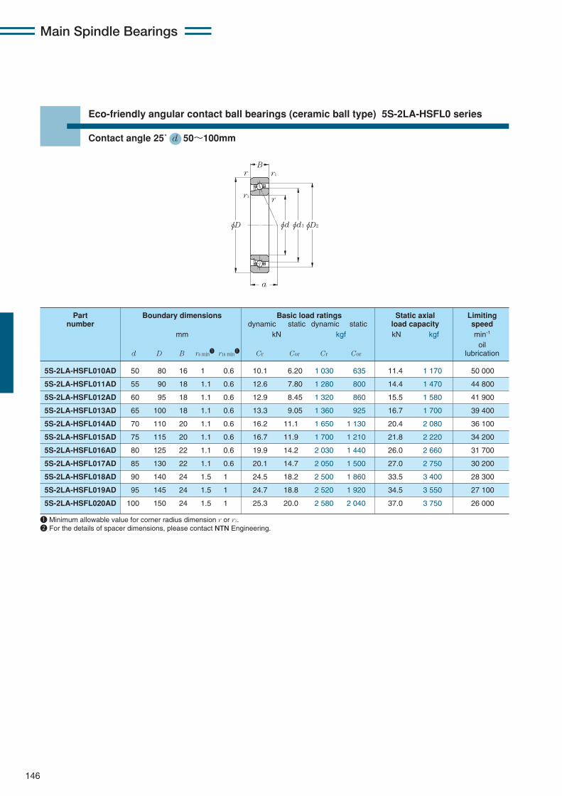
Main Spindle Bearings
146
Eco-friendly angular contact ball bearings (ceramic ball type) 5S-2LA-HSFL0 series
Contact angle 25˚ d 50〜100mm
φD φD2φdφd1
B
a
r1
r1
r
r
5S-2LA-HSFL010AD 50 80 16 1 0.6 10.1 6.20 1 030 635 11.4 1 170 50 000
5S-2LA-HSFL011AD 55 90 18 1.1 0.6 12.6 7.80 1 280 800 14.4 1 470 44 800
5S-2LA-HSFL012AD 60 95 18 1.1 0.6 12.9 8.45 1 320 860 15.5 1 580 41 900
5S-2LA-HSFL013AD 65 100 18 1.1 0.6 13.3 9.05 1 360 925 16.7 1 700 39 400
5S-2LA-HSFL014AD 70 110 20 1.1 0.6 16.2 11.1 1 650 1 130 20.4 2 080 36 100
5S-2LA-HSFL015AD 75 115 20 1.1 0.6 16.7 11.9 1 700 1 210 21.8 2 220 34 200
5S-2LA-HSFL016AD 80 125 22 1.1 0.6 19.9 14.2 2 030 1 440 26.0 2 660 31 700
5S-2LA-HSFL017AD 85 130 22 1.1 0.6 20.1 14.7 2 050 1 500 27.0 2 750 30 200
5S-2LA-HSFL018AD 90 140 24 1.5 1 24.5 18.2 2 500 1 860 33.5 3 400 28 300
5S-2LA-HSFL019AD 95 145 24 1.5 1 24.7 18.8 2 520 1 920 34.5 3 550 27 100
5S-2LA-HSFL020AD 100 150 24 1.5 1 25.3 20.0 2 580 2 040 37.0 3 750 26 000
Part Boundary dimensions Basic load ratings Static axial Limitingnumber dynamic static dynamic static load capacity speed
mm kN kgf kN kgf min-1
oild D B rs min1 r1s min1 Cr Cor Cr Cor lubrication
1 Minimum allowable value for corner radius dimension r or r1.2 For the details of spacer dimensions, please contact NTN Engineering.
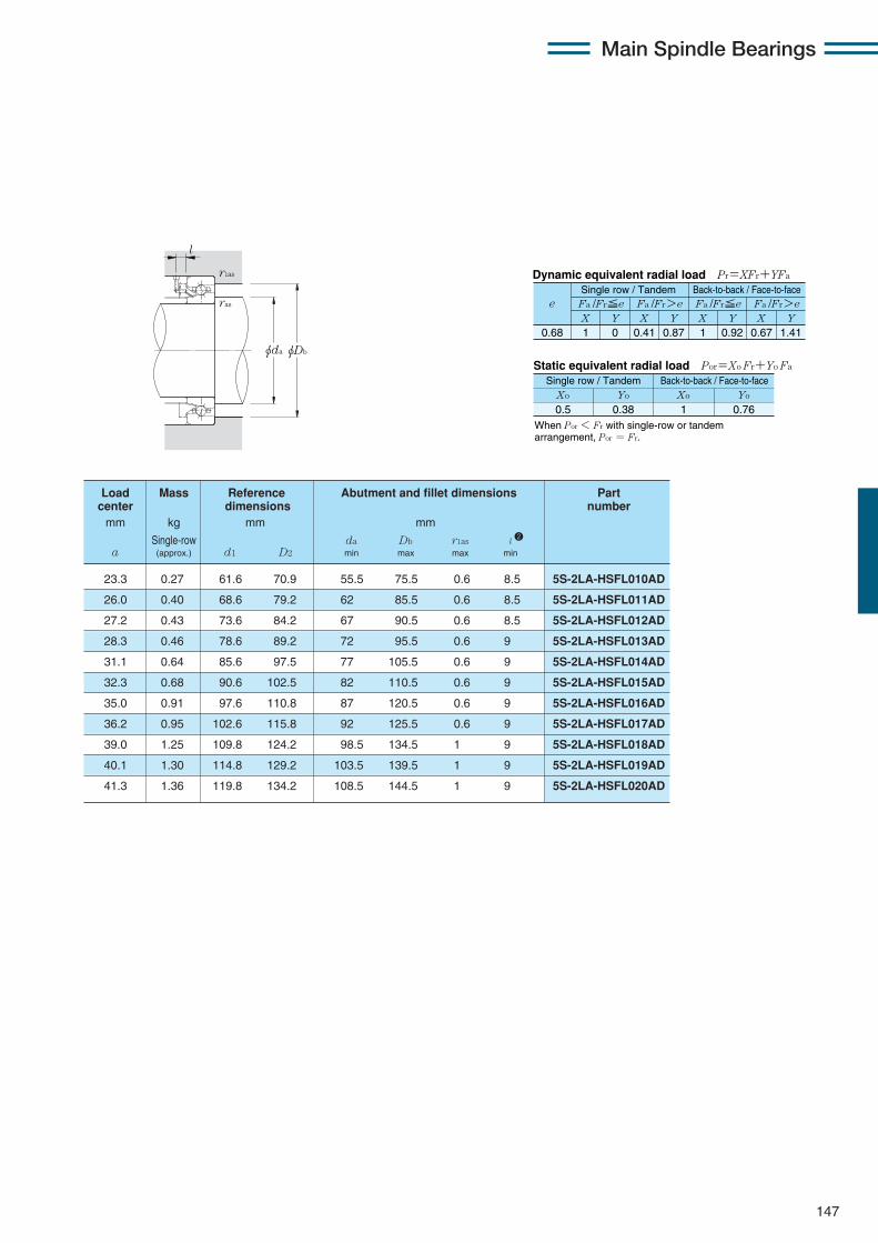
Main Spindle Bearings
147
X Y X Y X Y X Y0.68 1 0 0.41 0.87 1 0.92 0.67 1.41
Fa /Fr≦e Fa /Fr>e Fa /Fr≦e Fa /Fr>ee
Static equivalent radial load Por=Xo Fr+Yo Fa
When Por < Fr with single-row or tandem arrangement, Por = Fr.
Xo Yo Xo Yo
0.5 0.38 1 0.76
Dynamic equivalent radial load Pr=XFr+YFa
Single row / Tandem Back-to-back / Face-to-face
Single row / Tandem Back-to-back / Face-to-face
φDbφda
r1as
ras
l
23.3 0.27 61.6 70.9 55.5 75.5 0.6 8.5 5S-2LA-HSFL010AD
26.0 0.40 68.6 79.2 62 85.5 0.6 8.5 5S-2LA-HSFL011AD
27.2 0.43 73.6 84.2 67 90.5 0.6 8.5 5S-2LA-HSFL012AD
28.3 0.46 78.6 89.2 72 95.5 0.6 9 5S-2LA-HSFL013AD
31.1 0.64 85.6 97.5 77 105.5 0.6 9 5S-2LA-HSFL014AD
32.3 0.68 90.6 102.5 82 110.5 0.6 9 5S-2LA-HSFL015AD
35.0 0.91 97.6 110.8 87 120.5 0.6 9 5S-2LA-HSFL016AD
36.2 0.95 102.6 115.8 92 125.5 0.6 9 5S-2LA-HSFL017AD
39.0 1.25 109.8 124.2 98.5 134.5 1 9 5S-2LA-HSFL018AD
40.1 1.30 114.8 129.2 103.5 139.5 1 9 5S-2LA-HSFL019AD
41.3 1.36 119.8 134.2 108.5 144.5 1 9 5S-2LA-HSFL020AD
Load Mass Reference Abutment and fillet dimensions Partcenter dimensions numbermm kg mm mm
Single-row da Db r1as l 2
a (approx.) d1 D2 min max max min

148
Main Spindle Bearings
Air-oil lubricated high-speed angular ball bearings with re-lubricating hole on the outer ring5S-2LA-HSEW9U type
Contact angle 20˚ d 50〜100mm
r1
r1 r
r
a
φD φD1 φd2
BSn
Sb
Bn
Gb Gb
Bn
φD2φd φd1
Enlargedview
5S-2LA-HSEW910U 50 72 12 2.2 6.6 1.2 1.3 0.6 0.3 10.7 5.50 1 090 560 8.55 875 46 100
5S-2LA-HSEW911U 55 80 13 2.8 7.2 1.2 1.3 1 0.6 13.3 6.85 1 360 700 10.6 1 090 41 700
5S-2LA-HSEW912U 60 85 13 2.8 7.2 1.2 1.3 1 0.6 13.8 7.50 1 410 765 11.6 1 190 38 800
5S-2LA-HSEW913U 65 90 13 2.8 7.2 1.2 1.3 1 0.6 13.9 7.85 1 420 800 12.2 1 250 36 300
5S-2LA-HSEW914U 70 100 16 3.1 9.3 1.4 1.9 1 0.6 20.4 11.2 2 080 1 140 17.4 1 780 33 100
5S-2LA-HSEW915U 75 105 16 3.1 9.3 1.4 1.9 1 0.6 21.2 12.2 2 160 1 240 19.0 1 940 31 300
5S-2LA-HSEW916U 80 110 16 3.1 9.3 1.4 1.9 1 0.6 21.4 12.7 2 190 1 290 19.8 2 020 29 600
5S-2LA-HSEW917U 85 120 18 4 10.4 1.6 1.9 1.1 0.6 29.1 16.8 2 960 1 710 26.1 2 670 27 400
5S-2LA-HSEW918U 90 125 18 4 10.4 1.6 1.9 1.1 0.6 30.0 18.1 3 100 1 850 28.3 2 890 26 200
5S-2LA-HSEW919U 95 130 18 4 10.4 1.6 1.9 1.1 0.6 30.5 18.9 3 100 1 930 29.4 3 000 25 000
5S-2LA-HSEW920U 100 140 20 4 12 1.6 1.9 1.1 0.6 35.5 22.1 3 600 2 260 34.0 3 500 23 400
Part Boundary dimensions Basic load ratings Static axial Limitingnumber dynamic static dynamic static load capacity speed
mm kN kgf kN kgf min-1
oild D B Bn Sn Sb Gb rs min1 r1s min1 Cr Cor Cr Cor (Static) lubrication
1 Minimum allowable value for corner radius dimension r or r1.
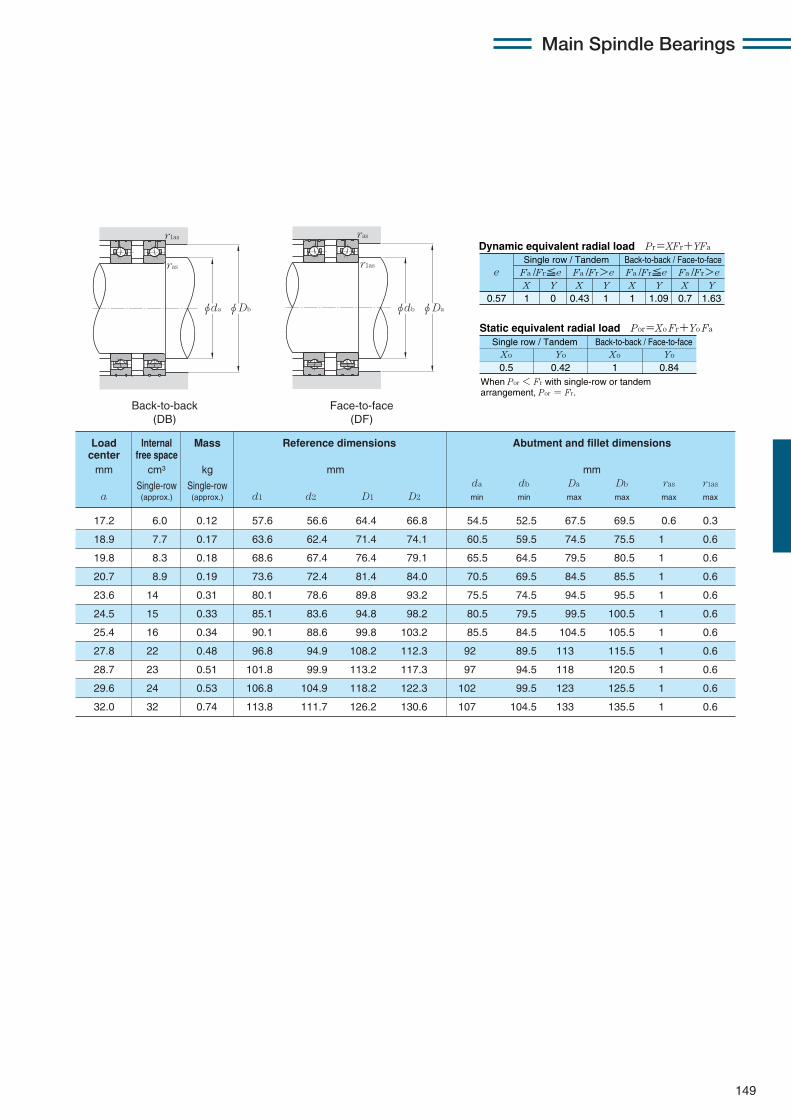
149
Main Spindle Bearings
17.2 6.0 0.12 57.6 56.6 64.4 66.8 54.5 52.5 67.5 69.5 0.6 0.3
18.9 7.7 0.17 63.6 62.4 71.4 74.1 60.5 59.5 74.5 75.5 1 0.6
19.8 8.3 0.18 68.6 67.4 76.4 79.1 65.5 64.5 79.5 80.5 1 0.6
20.7 8.9 0.19 73.6 72.4 81.4 84.0 70.5 69.5 84.5 85.5 1 0.6
23.6 14 0.31 80.1 78.6 89.8 93.2 75.5 74.5 94.5 95.5 1 0.6
24.5 15 0.33 85.1 83.6 94.8 98.2 80.5 79.5 99.5 100.5 1 0.6
25.4 16 0.34 90.1 88.6 99.8 103.2 85.5 84.5 104.5 105.5 1 0.6
27.8 22 0.48 96.8 94.9 108.2 112.3 92 89.5 113 115.5 1 0.6
28.7 23 0.51 101.8 99.9 113.2 117.3 97 94.5 118 120.5 1 0.6
29.6 24 0.53 106.8 104.9 118.2 122.3 102 99.5 123 125.5 1 0.6
32.0 32 0.74 113.8 111.7 126.2 130.6 107 104.5 133 135.5 1 0.6
Load Internal Mass Reference dimensions Abutment and fillet dimensionscenter free spacemm cm3 kg mm mm
Single-row Single-row da db Da Db ras r1as
a (approx.) (approx.) d1 d2 D1 D2 min min max max max max
X Y X Y X Y X Y0.57 1 0 0.43 1 1 1.09 0.7 1.63
Fa /Fr≦e Fa /Fr>e Fa /Fr≦e Fa /Fr>ee
Static equivalent radial load Por=Xo Fr+Yo Fa
When Por < Fr with single-row or tandem arrangement, Por = Fr.
Xo Yo Xo Yo
0.5 0.42 1 0.84
Dynamic equivalent radial load Pr=XFr+YFa
Single row / Tandem Back-to-back / Face-to-face
Single row / Tandem Back-to-back / Face-to-face
Back-to-back(DB)
Face-to-face(DF)
φda
ras
ras
r1as
r1as
φDb φdb φDa

150
Main Spindle Bearings
5S-2LA-HSEW910UAD 50 72 12 2.2 6.6 1.2 1.3 0.6 0.3 10.3 5.30 1 050 545 9.75 995 41 000
5S-2LA-HSEW911UAD 55 80 13 2.8 7.2 1.2 1.3 1 0.6 12.9 6.65 1 310 680 12.1 1 240 37 000
5S-2LA-HSEW912UAD 60 85 13 2.8 7.2 1.2 1.3 1 0.6 13.3 7.3 1 360 740 13.3 1 360 34 500
5S-2LA-HSEW913UAD 65 90 13 2.8 7.2 1.2 1.3 1 0.6 13.5 7.6 1 370 775 13.9 1 420 32 300
5S-2LA-HSEW914UAD 70 100 16 3.1 9.3 1.4 1.9 1 0.6 19.7 10.8 2 010 1 100 19.9 2 030 29 400
5S-2LA-HSEW915UAD 75 105 16 3.1 9.3 1.4 1.9 1 0.6 20.5 11.8 2 090 1 200 21.5 2 200 27 800
5S-2LA-HSEW916UAD 80 110 16 3.1 9.3 1.4 1.9 1 0.6 20.7 12.3 2 110 1 250 22.5 2 300 26 300
5S-2LA-HSEW917UAD 85 120 18 4 10.4 1.6 1.9 1.1 0.6 28.1 16.2 2 860 1 660 29.4 3 000 24 400
5S-2LA-HSEW918UAD 90 125 18 4 10.4 1.6 1.9 1.1 0.6 29.2 17.6 2 980 1 790 31.5 3 250 23 300
5S-2LA-HSEW919UAD 95 130 18 4 10.4 1.6 1.9 1.1 0.6 29.5 18.3 3 000 1 870 33.0 3 400 22 200
5S-2LA-HSEW920UAD 100 140 20 4 12 1.6 1.9 1.1 0.6 34.5 21.4 3 500 2 190 39.0 4 000 20 800
Part Boundary dimensions Basic load ratings Static axial Limitingnumber dynamic static dynamic static load capacity speed
mm kN kgf kN kgf min-1
oild D B Bn Sn Sb Gb rs min1 r1s min1 Cr Cor Cr Cor (Static) lubrication
1 Minimum allowable value for corner radius dimension r or r1.
Air-oil lubricated high-speed angular ball bearings with re-lubricating hole on the outer ring5S-2LA-HSEW9U type
Contact angle 25˚ d 50〜100mm
r1
r1 r
r
a
φD φD1 φd2
BSn
Sb
Bn
Gb Gb
Bn
φD2φd φd1
Enlargedview

151
Main Spindle Bearings
20.3 6.0 0.12 57.6 56.6 64.4 66.7 54.5 52.5 67.5 69.5 0.6 0.3
22.4 7.7 0.17 63.6 62.4 71.4 74.1 60.5 59.5 74.5 75.5 1 0.6
23.5 8.3 0.18 68.6 67.4 76.4 79.0 65.5 64.5 79.5 80.5 1 0.6
24.7 8.9 0.19 73.6 72.4 81.4 84.0 70.5 69.5 84.5 85.5 1 0.6
28.0 14 0.31 80.1 78.6 89.8 93.2 75.5 74.5 94.5 95.5 1 0.6
29.1 15 0.33 85.1 83.6 94.8 98.2 80.5 79.5 99.5 100.5 1 0.6
30.3 16 0.34 90.1 88.6 99.8 103.2 85.5 84.5 104.5 105.5 1 0.6
33.1 22 0.48 96.8 94.9 108.2 112.3 92 89.5 113 115.5 1 0.6
34.2 23 0.51 101.8 99.9 113.2 117.3 97 94.5 118 120.5 1 0.6
35.4 24 0.53 106.8 104.9 118.2 122.3 102 99.5 123 125.5 1 0.6
38.2 32 0.74 113.8 111.7 126.2 130.6 107 104.5 133 135.5 1 0.6
Load Internal Mass Reference dimensions Abutment and fillet dimensionscenter free spacemm cm3 kg mm mm
Single-row Single-row da db Da Db ras r1as
a (approx.) (approx.) d1 d2 D1 D2 min min max max max max
X Y X Y X Y X Y0.68 1 0 0.41 0.87 1 0.92 0.67 1.41
Fa /Fr≦e Fa /Fr>e Fa /Fr≦e Fa /Fr>ee
Static equivalent radial load Por=Xo Fr+Yo Fa
When Por < Fr with single-row or tandem arrangement, Por = Fr.
Xo Yo Xo Yo
0.5 0.38 1 0.76
Dynamic equivalent radial load Pr=XFr+YFa
Single row / Tandem Back-to-back / Face-to-face
Single row / Tandem Back-to-back / Face-to-face
Back-to-back(DB)
Face-to-face(DF)
φda
ras
ras
r1as
r1as
φDb φdb φDa

152
Main Spindle Bearings
5S-2LA-HSEW010 50 80 16 3.4 9.3 1.4 1.9 1 0.6 15.5 7.75 1 580 790 12.1 1 230 43 300
5S-2LA-HSEW011 55 90 18 4.3 9.7 1.4 1.9 1.1 0.6 16.8 9.20 1 720 935 14.4 1 460 38 800
5S-2LA-HSEW012 60 95 18 4.3 9.7 1.4 1.9 1.1 0.6 17.6 10.2 1 800 1 040 15.9 1 620 36 300
5S-2LA-HSEW013 65 100 18 4 10.4 1.6 1.9 1.1 0.6 17.9 10.7 1 830 1 090 16.7 1 710 34 100
5S-2LA-HSEW014 70 110 20 4 11.6 1.6 1.9 1.1 0.6 21.9 13.5 2 230 1 370 21.1 2 150 31 200
5S-2LA-HSEW015 75 115 20 4 11.6 1.6 2.4 1.1 0.6 23.3 15.2 2 380 1 550 23.8 2 420 29 600
5S-2LA-HSEW016 80 125 22 4.7 12.2 1.6 2.4 1.1 0.6 26.7 17.4 2 720 1 770 27.2 2 780 27 400
5S-2LA-HSEW017 85 130 22 4.7 12.2 1.6 2.4 1.1 0.6 27.0 18.1 2 760 1 850 28.4 2 900 26 200
5S-2LA-HSEW018 90 140 24 5.5 14.5 1.6 1.9 1.5 1 31.5 21.3 3 200 2 170 33.5 3 400 24 500
5S-2LA-HSEW019 95 145 24 5.5 14.5 1.6 2.4 1.5 1 31.5 22.1 3 250 2 260 34.5 3 550 23 400
5S-2LA-HSEW020 100 150 24 5.5 14.5 1.6 1.9 1.5 1 33.0 23.8 3 350 2 420 37.5 3 800 22 500
Part Boundary dimensions Basic load ratings Static axial Limitingnumber dynamic static dynamic static load capacity speed
mm kN kgf kN kgf min-1
oild D B Bn Sn Sb Gb rs min1 r1s min1 Cr Cor Cr Cor (Static) lubrication
1 Minimum allowable value for corner radius dimension r or r1.
Air-oil lubricated high-speed angular ball bearings with re-lubricating hole on the outer ring5S-2LA-HSEW0 type
Contact angle 20˚ d 50〜100mm
r1
r1 r
r
a
φD φD1 φd2
BSn
Sb
Bn
Gb Gb
Bn
φD2φd φd1
Enlargedview

153
Main Spindle Bearings
19.9 12 0.23 60.1 58.6 69.9 73.2 55.5 54.5 74.5 75.5 1 0.6
22.3 16 0.37 67.6 66.2 77.4 80.8 62 59.5 83 85.5 1 0.6
23.2 17 0.40 72.6 71.2 82.4 85.8 67 64.5 88 90.5 1 0.6
24.1 18 0.42 77.6 76.2 87.4 90.8 72 69.5 93 95.5 1 0.6
26.5 24 0.60 84.8 83.0 95.2 99.1 77 74.5 103 105.5 1 0.6
27.4 25 0.64 89.8 88.0 100.2 104.1 82 79.5 108 110.5 1 0.6
29.8 34 0.86 96.8 94.9 108.2 112.5 87 84.5 118 120.5 1 0.6
30.7 35 0.90 101.8 99.9 113.2 117.4 92 89.5 123 125.5 1 0.6
33.1 45 1.18 108.8 106.7 121.2 125.8 98.5 95.5 131.5 134.5 1.5 1
34.0 47 1.23 113.8 111.7 126.2 130.8 103.5 100.5 136.5 139.5 1.5 1
34.9 49 1.28 118.8 116.7 131.2 135.8 108.5 105.5 141.5 144.5 1.5 1
Load Internal Mass Reference dimensions Abutment and fillet dimensionscenter free spacemm cm3 kg mm mm
Single-row Single-row da db Da Db ras r1as
a (approx.) (approx.) d1 d2 D1 D2 min min max max max max
X Y X Y X Y X Y0.57 1 0 0.43 1 1 1.09 0.7 1.63
Fa /Fr≦e Fa /Fr>e Fa /Fr≦e Fa /Fr>ee
Static equivalent radial load Por=Xo Fr+Yo Fa
When Por < Fr with single-row or tandem arrangement, Por = Fr.
Xo Yo Xo Yo
0.5 0.42 1 0.84
Dynamic equivalent radial load Pr=XFr+YFa
Single row / Tandem Back-to-back / Face-to-face
Single row / Tandem Back-to-back / Face-to-face
Back-to-back(DB)
Face-to-face(DF)
φda
ras
ras
r1as
r1as
φDb φdb φDa
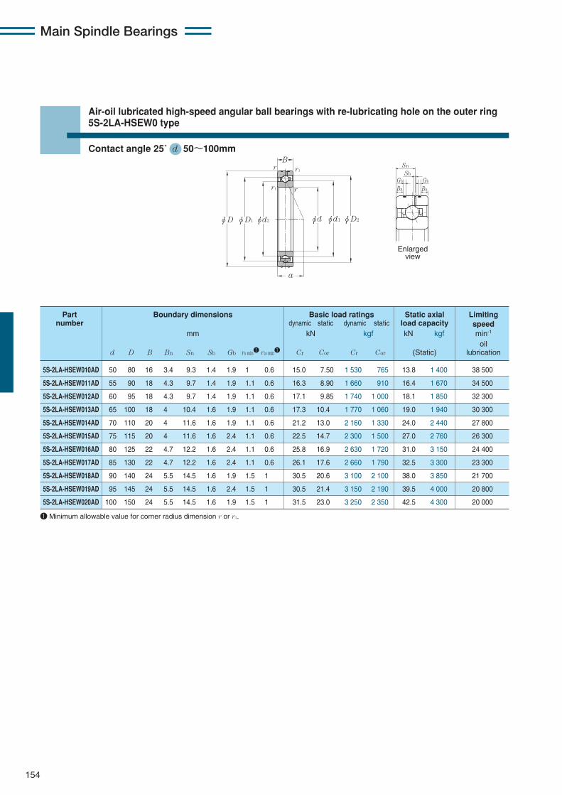
154
Main Spindle Bearings
5S-2LA-HSEW010AD 50 80 16 3.4 9.3 1.4 1.9 1 0.6 15.0 7.50 1 530 765 13.8 1 400 38 500
5S-2LA-HSEW011AD 55 90 18 4.3 9.7 1.4 1.9 1.1 0.6 16.3 8.90 1 660 910 16.4 1 670 34 500
5S-2LA-HSEW012AD 60 95 18 4.3 9.7 1.4 1.9 1.1 0.6 17.1 9.85 1 740 1 000 18.1 1 850 32 300
5S-2LA-HSEW013AD 65 100 18 4 10.4 1.6 1.9 1.1 0.6 17.3 10.4 1 770 1 060 19.0 1 940 30 300
5S-2LA-HSEW014AD 70 110 20 4 11.6 1.6 1.9 1.1 0.6 21.2 13.0 2 160 1 330 24.0 2 440 27 800
5S-2LA-HSEW015AD 75 115 20 4 11.6 1.6 2.4 1.1 0.6 22.5 14.7 2 300 1 500 27.0 2 760 26 300
5S-2LA-HSEW016AD 80 125 22 4.7 12.2 1.6 2.4 1.1 0.6 25.8 16.9 2 630 1 720 31.0 3 150 24 400
5S-2LA-HSEW017AD 85 130 22 4.7 12.2 1.6 2.4 1.1 0.6 26.1 17.6 2 660 1 790 32.5 3 300 23 300
5S-2LA-HSEW018AD 90 140 24 5.5 14.5 1.6 1.9 1.5 1 30.5 20.6 3 100 2 100 38.0 3 850 21 700
5S-2LA-HSEW019AD 95 145 24 5.5 14.5 1.6 2.4 1.5 1 30.5 21.4 3 150 2 190 39.5 4 000 20 800
5S-2LA-HSEW020AD 100 150 24 5.5 14.5 1.6 1.9 1.5 1 31.5 23.0 3 250 2 350 42.5 4 300 20 000
Part Boundary dimensions Basic load ratings Static axial Limitingnumber dynamic static dynamic static load capacity speed
mm kN kgf kN kgf min-1
oild D B Bn Sn Sb Gb rs min1 r1s min1 Cr Cor Cr Cor (Static) lubrication
1 Minimum allowable value for corner radius dimension r or r1.
Air-oil lubricated high-speed angular ball bearings with re-lubricating hole on the outer ring5S-2LA-HSEW0 type
Contact angle 25˚ d 50〜100mm
r1
r1 r
r
a
φD φD1 φd2
BSn
Sb
Bn
Gb Gb
Bn
φD2φd φd1
Enlargedview

155
Main Spindle Bearings
23.3 12 0.23 60.1 58.6 69.9 73.2 55.5 54.5 74.5 75.5 1 0.6
26.1 16 0.37 67.6 66.2 77.4 80.8 62 59.5 83 85.5 1 0.6
27.2 17 0.40 72.6 71.2 82.4 85.8 67 64.5 88 90.5 1 0.6
28.4 18 0.40 77.6 76.2 87.4 90.8 72 69.5 93 95.5 1 0.6
31.1 24 0.60 84.8 83.0 95.2 99.1 77 74.5 103 105.5 1 0.6
32.3 25 0.64 89.8 88.0 100.2 104.1 82 79.5 108 110.5 1 0.6
35.1 34 0.86 96.8 94.9 108.2 112.5 87 84.5 118 120.5 1 0.6
36.2 35 0.90 101.8 99.9 113.2 117.4 92 89.5 123 125.5 1 0.6
39.0 45 1.18 108.8 106.7 121.2 125.8 98.5 95.5 131.5 134.5 1.5 1
40.2 47 1.23 113.8 111.7 126.2 130.8 103.5 100.5 136.5 139.5 1.5 1
41.3 49 1.28 118.8 116.7 131.2 135.8 108.5 105.5 141.5 144.5 1.5 1
Load Internal Mass Reference dimensions Abutment and fillet dimensionscenter free spacemm cm3 kg mm mm
Single-row Single-row da db Da Db ras r1as
a (approx.) (approx.) d1 d2 D1 D2 min min max max max max
X Y X Y X Y X Y0.68 1 0 0.41 0.87 1 0.92 0.67 1.41
Fa /Fr≦e Fa /Fr>e Fa /Fr≦e Fa /Fr>ee
Static equivalent radial load Por=Xo Fr+Yo Fa
When Por < Fr with single-row or tandem arrangement, Por = Fr.
Xo Yo Xo Yo
0.5 0.38 1 0.76
Dynamic equivalent radial load Pr=XFr+YFa
Single row / Tandem Back-to-back / Face-to-face
Single row / Tandem Back-to-back / Face-to-face
Back-to-back(DB)
Face-to-face(DF)
φda
ras
ras
r1as
r1as
φDb φdb φDa
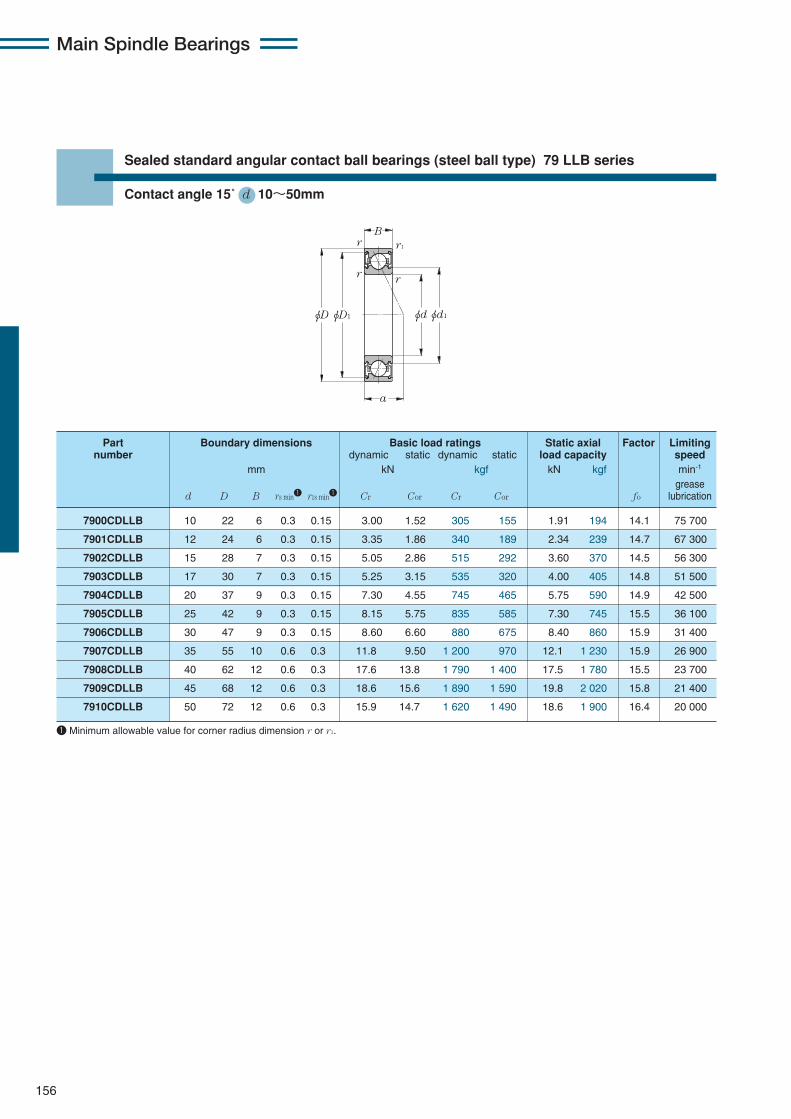
Main Spindle Bearings
156
Sealed standard angular contact ball bearings (steel ball type) 79 LLB series
Contact angle 15˚ d 10〜50mm
φDφD1 φdφd1
B
a
r
r
r1
r
7900CDLLB 10 22 6 0.3 0.15 3.00 1.52 305 155 1.91 194 14.1 75 700
7901CDLLB 12 24 6 0.3 0.15 3.35 1.86 340 189 2.34 239 14.7 67 300
7902CDLLB 15 28 7 0.3 0.15 5.05 2.86 515 292 3.60 370 14.5 56 300
7903CDLLB 17 30 7 0.3 0.15 5.25 3.15 535 320 4.00 405 14.8 51 500
7904CDLLB 20 37 9 0.3 0.15 7.30 4.55 745 465 5.75 590 14.9 42 500
7905CDLLB 25 42 9 0.3 0.15 8.15 5.75 835 585 7.30 745 15.5 36 100
7906CDLLB 30 47 9 0.3 0.15 8.60 6.60 880 675 8.40 860 15.9 31 400
7907CDLLB 35 55 10 0.6 0.3 11.8 9.50 1 200 970 12.1 1 230 15.9 26 900
7908CDLLB 40 62 12 0.6 0.3 17.6 13.8 1 790 1 400 17.5 1 780 15.5 23 700
7909CDLLB 45 68 12 0.6 0.3 18.6 15.6 1 890 1 590 19.8 2 020 15.8 21 400
7910CDLLB 50 72 12 0.6 0.3 15.9 14.7 1 620 1 490 18.6 1 900 16.4 20 000
Part Boundary dimensions Basic load ratings Static axial Factor Limitingnumber dynamic static dynamic static load capacity speed
mm kN kgf kN kgf min-1
greased D B rs min1 r1s min1 Cr Cor Cr Cor fo lubrication
1 Minimum allowable value for corner radius dimension r or r1.
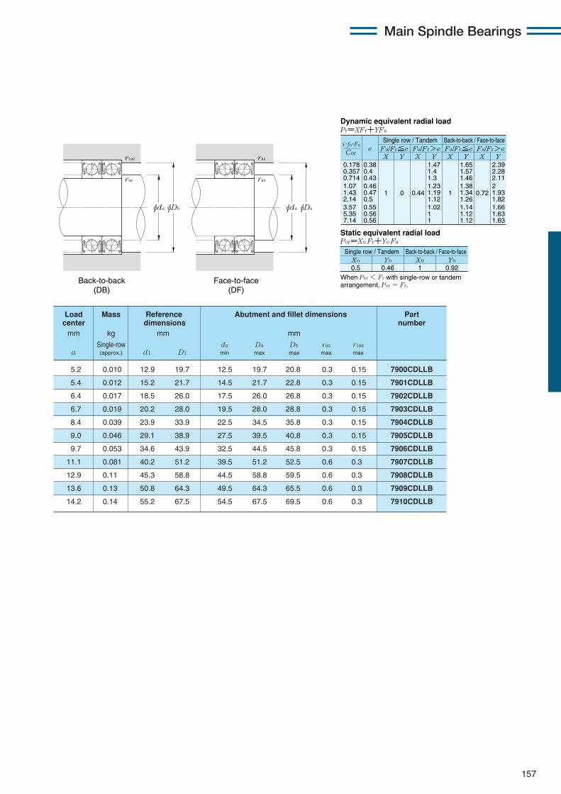
Main Spindle Bearings
157
0.178 0.357 0.714 1.07 1.43 2.14 3.57 5.35 7.14
eX Y
Dynamic equivalent radial loadPr=XFr+YFa
Static equivalent radial loadPor=Xo Fr+Yo Fa
Fa/Fr≦e Fa/Fr>eSingle row / Tandem Back-to-back / Face-to-face
Fa/Fr≦e Fa/Fr>eX Y X Y X Y
0.38 0.4 0.43 0.46 0.47 0.5 0.55 0.56 0.56
1 0 0.44
1.47 1.4 1.3 1.23 1.19 1.12 1.02 1 1
1
1.65 1.57 1.46 1.38 1.34 1.26 1.14 1.12 1.12
0.72
2.39 2.28 2.11 2 1.93 1.82 1.66 1.63 1.63
Xo
Single row / Tandem Back-to-back / Face-to-face
0.5Yo Xo Yo
0.46 1 0.92
Cor
i・fo・Fa
When Por < Fr with single-row or tandem arrangement, Por = Fr.Back-to-back
(DB)Face-to-face
(DF)
φdaφDb
r1as
ras
φdaφDa
ras
ras
5.2 0.010 12.9 19.7 12.5 19.7 20.8 0.3 0.15 7900CDLLB
5.4 0.012 15.2 21.7 14.5 21.7 22.8 0.3 0.15 7901CDLLB
6.4 0.017 18.5 26.0 17.5 26.0 26.8 0.3 0.15 7902CDLLB
6.7 0.019 20.2 28.0 19.5 28.0 28.8 0.3 0.15 7903CDLLB
8.4 0.039 23.9 33.9 22.5 34.5 35.8 0.3 0.15 7904CDLLB
9.0 0.046 29.1 38.9 27.5 39.5 40.8 0.3 0.15 7905CDLLB
9.7 0.053 34.6 43.9 32.5 44.5 45.8 0.3 0.15 7906CDLLB
11.1 0.081 40.2 51.2 39.5 51.2 52.5 0.6 0.3 7907CDLLB
12.9 0.11 45.3 58.8 44.5 58.8 59.5 0.6 0.3 7908CDLLB
13.6 0.13 50.8 64.3 49.5 64.3 65.5 0.6 0.3 7909CDLLB
14.2 0.14 55.2 67.5 54.5 67.5 69.5 0.6 0.3 7910CDLLB
Load Mass Reference Abutment and fillet dimensions Partcenter dimensions numbermm kg mm mm
Single-row da Da Db ras r1asa (approx.) d1 D1 min max max max max

Main Spindle Bearings
158
Sealed standard angular contact ball bearings (steel ball type) 79 LLB series
Contact angle 25˚ d 10〜50mm
7900ADLLB 10 22 6 0.3 0.15 2.88 1.45 294 148 2.20 225 65 600
7901ADLLB 12 24 6 0.3 0.15 3.20 1.77 325 181 2.61 267 58 300
7902ADLLB 15 28 7 0.3 0.15 4.80 2.74 490 279 4.40 450 48 800
7903ADLLB 17 30 7 0.3 0.15 5.00 3.00 510 305 4.75 485 44 700
7904ADLLB 20 37 9 0.3 0.15 6.95 4.35 710 445 6.35 645 36 800
7905ADLLB 25 42 9 0.3 0.15 7.75 5.50 790 560 7.75 790 31 300
7906ADLLB 30 47 9 0.3 0.15 8.15 6.30 830 640 8.65 885 27 300
7907ADLLB 35 55 10 0.6 0.3 11.1 9.00 1 130 920 13.1 1 340 23 300
7908ADLLB 40 62 12 0.6 0.3 16.7 13.1 1 700 1 330 19.3 1 960 20 600
7909ADLLB 45 68 12 0.6 0.3 17.6 14.8 1 790 1 510 21.5 2 190 18 600
7910ADLLB 50 72 12 0.6 0.3 15.0 13.9 1 530 1 420 13.6 1 380 17 400
Part Boundary dimensions Basic load ratings Static axial Limitingnumber dynamic static dynamic static load capacity speed
mm kN kgf kN kgf min-1
greased D B rs min1 r1s min1 Cr Cor Cr Cor lubrication
φDφD1 φdφd1
B
a
r
r
r1
r
1 Minimum allowable value for corner radius dimension r or r1.
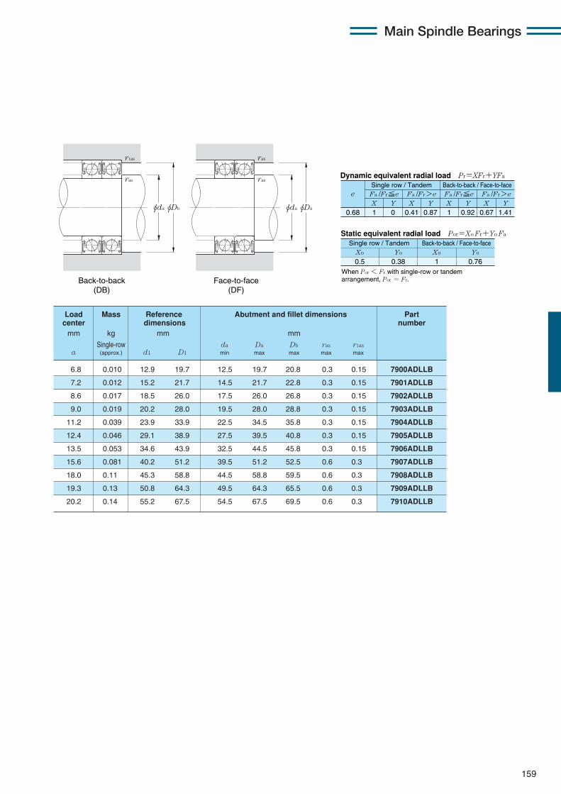
Main Spindle Bearings
159
X Y X Y X Y X Y0.68 1 0 0.41 0.87 1 0.92 0.67 1.41
Fa /Fr≦e Fa /Fr>e Fa /Fr≦e Fa /Fr>ee
Static equivalent radial load Por=Xo Fr+Yo Fa
When Por < Fr with single-row or tandem arrangement, Por = Fr.
Xo Yo Xo Yo
0.5 0.38 1 0.76
Dynamic equivalent radial load Pr=XFr+YFa
Single row / Tandem Back-to-back / Face-to-face
Single row / Tandem Back-to-back / Face-to-face
6.8 0.010 12.9 19.7 12.5 19.7 20.8 0.3 0.15 7900ADLLB
7.2 0.012 15.2 21.7 14.5 21.7 22.8 0.3 0.15 7901ADLLB
8.6 0.017 18.5 26.0 17.5 26.0 26.8 0.3 0.15 7902ADLLB
9.0 0.019 20.2 28.0 19.5 28.0 28.8 0.3 0.15 7903ADLLB
11.2 0.039 23.9 33.9 22.5 34.5 35.8 0.3 0.15 7904ADLLB
12.4 0.046 29.1 38.9 27.5 39.5 40.8 0.3 0.15 7905ADLLB
13.5 0.053 34.6 43.9 32.5 44.5 45.8 0.3 0.15 7906ADLLB
15.6 0.081 40.2 51.2 39.5 51.2 52.5 0.6 0.3 7907ADLLB
18.0 0.11 45.3 58.8 44.5 58.8 59.5 0.6 0.3 7908ADLLB
19.3 0.13 50.8 64.3 49.5 64.3 65.5 0.6 0.3 7909ADLLB
20.2 0.14 55.2 67.5 54.5 67.5 69.5 0.6 0.3 7910ADLLB
Load Mass Reference Abutment and fillet dimensions Partcenter dimensions numbermm kg mm mm
Single-row da Da Db ras r1asa (approx.) d1 D1 min max max max max
Back-to-back (DB)
Face-to-face (DF)
φdaφDb
r1as
ras
φdaφDa
ras
ras

Main Spindle Bearings
160
Sealed standard angular contact ball bearings (steel ball type) 70 LLB series
Contact angle 15˚ d 10〜50mm
φDφD1 φdφd1
B
a
r
r
r1
r
7000CDLLB 10 26 8 0.3 0.15 5.30 2.49 540 254 3.10 315 12.6 67 300
7001CDLLB 12 28 8 0.3 0.15 5.80 2.90 590 296 3.65 370 13.2 60 600
7002CDLLB 15 32 9 0.3 0.15 6.25 3.40 635 345 4.25 435 14.0 51 500
7003CDLLB 17 35 10 0.3 0.15 8.25 4.50 840 460 5.70 580 13.8 46 600
7004CDLLB 20 42 12 0.6 0.3 10.5 6.00 1 070 610 7.55 770 14.0 39 100
7005CDLLB 25 47 12 0.6 0.3 12.3 8.00 1 250 815 10.1 1 030 14.7 33 600
7006CDLLB 30 55 13 1 0.6 15.1 10.3 1 540 1 050 13.0 1 320 14.9 28 500
7007CDLLB 35 62 14 1 0.6 19.1 13.7 1 950 1 390 17.3 1 760 15.0 25 000
7008CDLLB 40 68 15 1 0.6 20.6 15.9 2 100 1 620 20.1 2 050 15.4 22 400
7009CDLLB 45 75 16 1 0.6 27.7 21.1 2 820 2 160 26.7 2 730 15.1 20 200
7010CDLLB 50 80 16 1 0.6 28.6 22.9 2 910 2 330 29.0 2 960 15.4 18 600
Part Boundary dimensions Basic load ratings Static axial Factor Limitingnumber dynamic static dynamic static load capacity speed
mm kN kgf kN kgf min-1
greased D B rs min1 r1s min1 Cr Cor Cr Cor fo lubrication
1 Minimum allowable value for corner radius dimension r or r1.
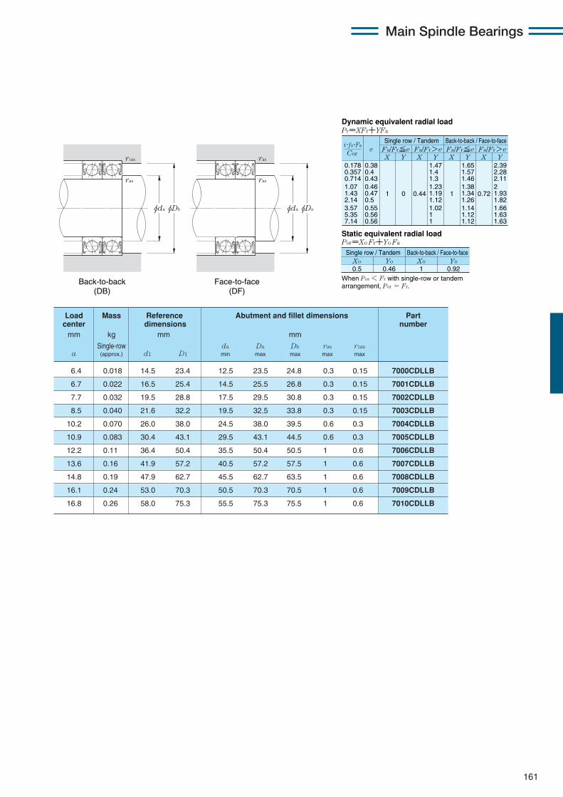
Main Spindle Bearings
161
0.178 0.357 0.714 1.07 1.43 2.14 3.57 5.35 7.14
eX Y
Dynamic equivalent radial loadPr=XFr+YFa
Static equivalent radial loadPor=Xo Fr+Yo Fa
Fa/Fr≦e Fa/Fr>eSingle row / Tandem Back-to-back / Face-to-face
Fa/Fr≦e Fa/Fr>eX Y X Y X Y
0.38 0.4 0.43 0.46 0.47 0.5 0.55 0.56 0.56
1 0 0.44
1.47 1.4 1.3 1.23 1.19 1.12 1.02 1 1
1
1.65 1.57 1.46 1.38 1.34 1.26 1.14 1.12 1.12
0.72
2.39 2.28 2.11 2 1.93 1.82 1.66 1.63 1.63
Xo
Single row / Tandem Back-to-back / Face-to-face
0.5Yo Xo Yo
0.46 1 0.92
Cor
i・fo・Fa
When Por < Fr with single-row or tandem arrangement, Por = Fr.
6.4 0.018 14.5 23.4 12.5 23.5 24.8 0.3 0.15 7000CDLLB
6.7 0.022 16.5 25.4 14.5 25.5 26.8 0.3 0.15 7001CDLLB
7.7 0.032 19.5 28.8 17.5 29.5 30.8 0.3 0.15 7002CDLLB
8.5 0.040 21.6 32.2 19.5 32.5 33.8 0.3 0.15 7003CDLLB
10.2 0.070 26.0 38.0 24.5 38.0 39.5 0.6 0.3 7004CDLLB
10.9 0.083 30.4 43.1 29.5 43.1 44.5 0.6 0.3 7005CDLLB
12.2 0.11 36.4 50.4 35.5 50.4 50.5 1 0.6 7006CDLLB
13.6 0.16 41.9 57.2 40.5 57.2 57.5 1 0.6 7007CDLLB
14.8 0.19 47.9 62.7 45.5 62.7 63.5 1 0.6 7008CDLLB
16.1 0.24 53.0 70.3 50.5 70.3 70.5 1 0.6 7009CDLLB
16.8 0.26 58.0 75.3 55.5 75.3 75.5 1 0.6 7010CDLLB
Load Mass Reference Abutment and fillet dimensions Partcenter dimensions numbermm kg mm mm
Single-row da Da Db ras r1asa (approx.) d1 D1 min max max max max
Back-to-back (DB)
Face-to-face (DF)
φdaφDb
r1as
ras
φdaφDa
ras
ras

Main Spindle Bearings
162
Sealed standard angular contact ball bearings (steel ball type) 70 LLB series
Contact angle 25˚ d 10〜50mm
φDφD1 φdφd1
B
a
r
r
r1
r
7000ADLLB 10 26 8 0.3 0.15 5.15 2.41 525 245 3.85 395 58 300
7001ADLLB 12 28 8 0.3 0.15 5.60 2.79 570 285 4.50 455 52 500
7002ADLLB 15 32 9 0.3 0.15 5.95 3.25 610 330 4.95 505 44 700
7003ADLLB 17 35 10 0.3 0.15 7.90 4.35 805 445 6.95 710 40 400
7004ADLLB 20 42 12 0.6 0.3 10.0 5.75 1 020 585 8.80 900 33 900
7005ADLLB 25 47 12 0.6 0.3 11.7 7.65 1 190 780 11.3 1 150 29 200
7006ADLLB 30 55 13 1 0.6 14.4 9.80 1 470 995 14.9 1 520 24 700
7007ADLLB 35 62 14 1 0.6 18.2 13.0 1 850 1 330 20.4 2 080 21 600
7008ADLLB 40 68 15 1 0.6 19.5 15.1 1 990 1 540 23.2 2 370 19 400
7009ADLLB 45 75 16 1 0.6 26.3 20.1 2 680 2 050 31.0 3 150 17 500
7010ADLLB 50 80 16 1 0.6 27.1 21.8 2 760 2 220 33.0 3 350 16 200
Part Boundary dimensions Basic load ratings Static axial Limitingnumber dynamic static dynamic static load capacity speed
mm kN kgf kN kgf min-1
greased D B rs min1 r1s min1 Cr Cor Cr Cor lubrication
1 Minimum allowable value for corner radius dimension r or r1.

Main Spindle Bearings
163
X Y X Y X Y X Y0.68 1 0 0.41 0.87 1 0.92 0.67 1.41
Fa /Fr≦e Fa /Fr>e Fa /Fr≦e Fa /Fr>ee
Static equivalent radial load Por=Xo Fr+Yo Fa
When Por < Fr with single-row or tandem arrangement, Por = Fr.
Xo Yo Xo Yo
0.5 0.38 1 0.76
Dynamic equivalent radial load Pr=XFr+YFa
Single row / Tandem Back-to-back / Face-to-face
Single row / Tandem Back-to-back / Face-to-face
8.3 0.018 14.5 23.4 12.5 23.5 24.8 0.3 0.15 7000ADLLB
8.7 0.022 16.5 25.4 14.5 25.5 26.8 0.3 0.15 7001ADLLB
10.0 0.032 19.5 28.8 17.5 29.5 30.8 0.3 0.15 7002ADLLB
11.1 0.040 21.6 32.2 19.5 32.5 33.8 0.3 0.15 7003ADLLB
13.3 0.070 26.0 38.0 24.5 38.0 39.5 0.6 0.3 7004ADLLB
14.5 0.083 30.4 43.1 29.5 43.1 44.5 0.6 0.3 7005ADLLB
16.5 0.11 36.4 50.4 35.5 50.4 50.5 1 0.6 7006ADLLB
18.4 0.16 41.9 57.2 40.5 57.2 57.5 1 0.6 7007ADLLB
20.2 0.19 47.9 62.7 45.5 62.7 63.5 1 0.6 7008ADLLB
22.1 0.24 53.0 70.3 50.5 70.3 70.5 1 0.6 7009ADLLB
23.3 0.26 58.0 75.3 55.5 75.3 75.5 1 0.6 7010ADLLB
Load Mass Reference Abutment and fillet dimensions Partcenter dimensions numbermm kg mm mm
Single-row da Da Db ras r1asa (approx.) d1 D1 min max max max max
Back-to-back (DB)
Face-to-face (DF)
φdaφDb
r1as
ras
φdaφDa
ras
ras

Main Spindle Bearings
164
Sealed standard angular contact ball bearings (ceramic ball type) 5S-79 LLB series
Contact angle 15˚ d 10〜50mm
φDφD1 φdφd1
B
a
r
r
r1
r
5S-7900CDLLB 10 22 6 0.3 0.15 3.00 1.05 305 107 1.19 121 9.8 89 800
5S-7901CDLLB 12 24 6 0.3 0.15 3.35 1.29 340 131 1.46 149 10.2 79 800
5S-7902CDLLB 15 28 7 0.3 0.15 5.05 1.98 515 202 2.25 230 10.0 66 800
5S-7903CDLLB 17 30 7 0.3 0.15 5.25 2.19 535 223 2.49 254 10.3 61 100
5S-7904CDLLB 20 37 9 0.3 0.15 7.30 3.15 745 325 3.60 365 10.3 50 400
5S-7905CDLLB 25 42 9 0.3 0.15 8.15 4.00 835 405 4.55 465 10.7 42 900
5S-7906CDLLB 30 47 9 0.3 0.15 8.60 4.60 880 470 5.25 535 11.0 37 300
5S-7907CDLLB 35 55 10 0.6 0.3 11.8 6.60 1 200 670 7.55 770 11.0 31 900
5S-7908CDLLB 40 62 12 0.6 0.3 17.6 9.55 1 790 975 10.9 1 110 10.8 28 200
5S-7909CDLLB 45 68 12 0.6 0.3 18.6 10.8 1 890 1 100 12.4 1 260 11.0 24 100
5S-7910CDLLB 50 72 12 0.6 0.3 15.9 10.2 1 620 1 040 11.7 1 190 11.3 22 500
Part Boundary dimensions Basic load ratings Static axial Factor Limitingnumber dynamic static dynamic static load capacity speed
mm kN kgf kN kgf min-1
greased D B rs min1 r1s min1 Cr Cor Cr Cor fo lubrication
1 Minimum allowable value for corner radius dimension r or r1.
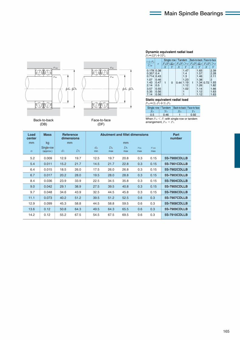
Main Spindle Bearings
165
0.178 0.357 0.714 1.07 1.43 2.14 3.57 5.35 7.14
eX Y
Dynamic equivalent radial loadPr=XFr+YFa
Static equivalent radial loadPor=Xo Fr+Yo Fa
Fa/Fr≦e Fa/Fr>eSingle row / Tandem Back-to-back / Face-to-face
Fa/Fr≦e Fa/Fr>eX Y X Y X Y
0.38 0.4 0.43 0.46 0.47 0.5 0.55 0.56 0.56
1 0 0.44
1.47 1.4 1.3 1.23 1.19 1.12 1.02 1 1
1
1.65 1.57 1.46 1.38 1.34 1.26 1.14 1.12 1.12
0.72
2.39 2.28 2.11 2 1.93 1.82 1.66 1.63 1.63
Xo
Single row / Tandem Back-to-back / Face-to-face
0.5Yo Xo Yo
0.46 1 0.92
Cor
i・fo・Fa
When Por < Fr with single-row or tandem arrangement, Por = Fr.
5.2 0.009 12.9 19.7 12.5 19.7 20.8 0.3 0.15 5S-7900CDLLB
5.4 0.011 15.2 21.7 14.5 21.7 22.8 0.3 0.15 5S-7901CDLLB
6.4 0.015 18.5 26.0 17.5 26.0 26.8 0.3 0.15 5S-7902CDLLB
6.7 0.017 20.2 28.0 19.5 28.0 28.8 0.3 0.15 5S-7903CDLLB
8.4 0.036 23.9 33.9 22.5 34.5 35.8 0.3 0.15 5S-7904CDLLB
9.0 0.042 29.1 38.9 27.5 39.5 40.8 0.3 0.15 5S-7905CDLLB
9.7 0.048 34.6 43.9 32.5 44.5 45.8 0.3 0.15 5S-7906CDLLB
11.1 0.073 40.2 51.2 39.5 51.2 52.5 0.6 0.3 5S-7907CDLLB
12.9 0.099 45.3 58.8 44.5 58.8 59.5 0.6 0.3 5S-7908CDLLB
13.6 0.12 50.8 64.3 49.5 64.3 65.5 0.6 0.3 5S-7909CDLLB
14.2 0.12 55.2 67.5 54.5 67.5 69.5 0.6 0.3 5S-7910CDLLB
Load Mass Reference Abutment and fillet dimensions Partcenter dimensions numbermm kg mm mm
Single-row da Da Db ras r1asa (approx.) d1 D1 min max max max max
Back-to-back (DB)
Face-to-face (DF)
φdaφDb
r1as
ras
φdaφDa
ras
ras

Main Spindle Bearings
166
Sealed standard angular contact ball bearings (ceramic ball type) 5S-79 LLB series
Contact angle 25˚ d 10〜50mm
φDφD1 φdφd1
B
a
r
r
r1
r
5S-7900ADLLB 10 22 6 0.3 0.15 2.88 1.01 294 103 1.52 155 79 700
5S-7901ADLLB 12 24 6 0.3 0.15 3.20 1.23 325 125 1.86 189 70 800
5S-7902ADLLB 15 28 7 0.3 0.15 4.80 1.90 490 193 2.86 292 59 300
5S-7903ADLLB 17 30 7 0.3 0.15 5.00 2.09 510 213 3.15 320 54 300
5S-7904ADLLB 20 37 9 0.3 0.15 6.95 3.00 710 310 4.55 465 44 700
5S-7905ADLLB 25 42 9 0.3 0.15 7.75 3.80 790 385 5.75 585 38 100
5S-7906ADLLB 30 47 9 0.3 0.15 8.15 4.35 830 445 6.60 670 33 100
5S-7907ADLLB 35 55 10 0.6 0.3 11.1 6.25 1 130 635 9.45 965 28 300
5S-7908ADLLB 40 62 12 0.6 0.3 16.7 9.05 1 700 925 13.7 1 400 25 000
5S-7909ADLLB 45 68 12 0.6 0.3 17.6 10.3 1 790 1 050 15.6 1 590 21 400
5S-7910ADLLB 50 72 12 0.6 0.3 15.0 9.60 1 530 980 14.6 1 490 20 000
Part Boundary dimensions Basic load ratings Static axial Limitingnumber dynamic static dynamic static load capacity speed
mm kN kgf kN kgf min-1
greased D B rs min1 r1s min1 Cr Cor Cr Cor lubrication
1 Minimum allowable value for corner radius dimension r or r1.
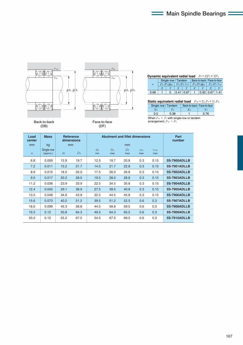
Main Spindle Bearings
167
X Y X Y X Y X Y0.68 1 0 0.41 0.87 1 0.92 0.67 1.41
Fa /Fr≦e Fa /Fr>e Fa /Fr≦e Fa /Fr>ee
Static equivalent radial load Por=Xo Fr+Yo Fa
When Por < Fr with single-row or tandem arrangement, Por = Fr.
Xo Yo Xo Yo
0.5 0.38 1 0.76
Dynamic equivalent radial load Pr=XFr+YFa
Single row / Tandem Back-to-back / Face-to-face
Single row / Tandem Back-to-back / Face-to-face
6.8 0.009 12.9 19.7 12.5 19.7 20.8 0.3 0.15 5S-7900ADLLB
7.2 0.011 15.2 21.7 14.5 21.7 22.8 0.3 0.15 5S-7901ADLLB
8.6 0.015 18.5 26.0 17.5 26.0 26.8 0.3 0.15 5S-7902ADLLB
9.0 0.017 20.2 28.0 19.5 28.0 28.8 0.3 0.15 5S-7903ADLLB
11.2 0.036 23.9 33.9 22.5 34.5 35.8 0.3 0.15 5S-7904ADLLB
12.4 0.042 29.1 38.9 27.5 39.5 40.8 0.3 0.15 5S-7905ADLLB
13.5 0.048 34.6 43.9 32.5 44.5 45.8 0.3 0.15 5S-7906ADLLB
15.6 0.073 40.2 51.2 39.5 51.2 52.5 0.6 0.3 5S-7907ADLLB
18.0 0.099 45.3 58.8 44.5 58.8 59.5 0.6 0.3 5S-7908ADLLB
19.3 0.12 50.8 64.3 49.5 64.3 65.5 0.6 0.3 5S-7909ADLLB
20.2 0.12 55.2 67.5 54.5 67.5 69.5 0.6 0.3 5S-7910ADLLB
Load Mass Reference Abutment and fillet dimensions Partcenter dimensions numbermm kg mm mm
Single-row da Da Db ras r1asa (approx.) d1 D1 min max max max max
Back-to-back (DB)
Face-to-face (DF)
φdaφDb
r1as
ras
φdaφDa
ras
ras

Main Spindle Bearings
168
Sealed standard angular contact ball bearings (ceramic ball type) 5S-70 LLB series
Contact angle 15˚ d 10〜50mm
φDφD1 φdφd1
B
a
r
r
r1
r
5S-7000CDLLB 10 26 8 0.3 0.15 5.30 1.73 540 176 1.93 197 8.8 80 600
5S-7001CDLLB 12 28 8 0.3 0.15 5.80 2.01 590 205 2.26 231 9.2 72 600
5S-7002CDLLB 15 32 9 0.3 0.15 6.25 2.35 635 239 2.66 271 9.7 61 800
5S-7003CDLLB 17 35 10 0.3 0.15 8.25 3.15 840 320 3.55 360 9.6 55 800
5S-7004CDLLB 20 42 12 0.6 0.3 10.5 4.15 1 070 425 4.70 480 9.7 46 800
5S-7005CDLLB 25 47 12 0.6 0.3 12.3 5.55 1 250 565 6.30 640 10.2 40 300
5S-7006CDLLB 30 55 13 1 0.6 15.1 7.10 1 540 725 8.10 825 10.3 34 100
5S-7007CDLLB 35 62 14 1 0.6 19.1 9.45 1 950 965 10.8 1 100 10.4 29 900
5S-7008CDLLB 40 68 15 1 0.6 20.6 11.0 2 100 1 120 12.6 1 280 10.6 26 900
5S-7009CDLLB 45 75 16 1 0.6 27.7 14.6 2 820 1 490 16.7 1 700 10.4 23 300
5S-7010CDLLB 50 80 16 1 0.6 28.6 15.9 2 910 1 620 18.1 1 850 10.6 21 500
Part Boundary dimensions Basic load ratings Static axial Factor Limitingnumber dynamic static dynamic static load capacity speed
mm kN kgf kN kgf min-1
greased D B rs min1 r1s min1 Cr Cor Cr Cor fo lubrication
1 Minimum allowable value for corner radius dimension r or r1.

Main Spindle Bearings
169
0.178 0.357 0.714 1.07 1.43 2.14 3.57 5.35 7.14
eX Y
Dynamic equivalent radial loadPr=XFr+YFa
Static equivalent radial loadPor=Xo Fr+Yo Fa
Fa/Fr≦e Fa/Fr>eSingle row / Tandem Back-to-back / Face-to-face
Fa/Fr≦e Fa/Fr>eX Y X Y X Y
0.38 0.4 0.43 0.46 0.47 0.5 0.55 0.56 0.56
1 0 0.44
1.47 1.4 1.3 1.23 1.19 1.12 1.02 1 1
1
1.65 1.57 1.46 1.38 1.34 1.26 1.14 1.12 1.12
0.72
2.39 2.28 2.11 2 1.93 1.82 1.66 1.63 1.63
Xo
Single row / Tandem Back-to-back / Face-to-face
0.5Yo Xo Yo
0.46 1 0.92
Cor
i・fo・Fa
When Por < Fr with single-row or tandem arrangement, Por = Fr.
6.4 0.014 14.5 23.4 12.5 23.5 24.8 0.3 0.15 5S-7000CDLLB
6.7 0.020 16.5 25.4 14.5 25.5 26.8 0.3 0.15 5S-7001CDLLB
7.7 0.029 19.5 28.8 17.5 29.5 30.8 0.3 0.15 5S-7002CDLLB
8.5 0.035 21.6 32.2 19.5 32.5 33.8 0.3 0.15 5S-7003CDLLB
10.2 0.064 26.0 38.0 24.5 38.0 39.5 0.6 0.3 5S-7004CDLLB
10.9 0.075 30.4 43.1 29.5 43.1 44.5 0.6 0.3 5S-7005CDLLB
12.2 0.096 36.4 50.4 35.5 50.4 50.5 1 0.6 5S-7006CDLLB
13.6 0.14 41.9 57.2 40.5 57.2 57.5 1 0.6 5S-7007CDLLB
14.8 0.17 47.9 62.7 45.5 62.7 63.5 1 0.6 5S-7008CDLLB
16.1 0.21 53.0 70.3 50.5 70.3 70.5 1 0.6 5S-7009CDLLB
16.8 0.23 58.0 75.3 55.5 75.3 75.5 1 0.6 5S-7010CDLLB
Load Mass Reference Abutment and fillet dimensions Partcenter dimensions numbermm kg mm mm
Single-row da Da Db ras r1asa (approx.) d1 D1 min max max max max
Back-to-back (DB)
Face-to-face (DF)
φdaφDb
r1as
ras
φdaφDa
ras
ras

Main Spindle Bearings
170
Sealed standard angular contact ball bearings (ceramic ball type) 5S-70 LLB series
Contact angle 25˚ d 10〜50mm
φDφD1 φdφd1
B
a
r
r
r1
r
5S-7000ADLLB 10 26 8 0.3 0.15 5.15 1.67 525 170 2.51 256 70 600
5S-7001ADLLB 12 28 8 0.3 0.15 5.60 1.93 570 197 2.92 297 63 500
5S-7002ADLLB 15 32 9 0.3 0.15 5.95 2.25 610 229 3.40 345 54 000
5S-7003ADLLB 17 35 10 0.3 0.15 7.90 3.00 805 305 4.55 465 48 800
5S-7004ADLLB 20 42 12 0.6 0.3 10.0 4.00 1 020 405 6.00 615 41 000
5S-7005ADLLB 25 47 12 0.6 0.3 11.7 5.30 1 190 540 8.00 815 35 300
5S-7006ADLLB 30 55 13 1 0.6 14.4 6.80 1 470 690 10.2 1 040 29 900
5S-7007ADLLB 35 62 14 1 0.6 18.2 9.00 1 850 920 13.6 1 390 26 200
5S-7008ADLLB 40 68 15 1 0.6 19.5 10.5 1 990 1 070 15.8 1 620 23 500
5S-7009ADLLB 45 75 16 1 0.6 26.3 14.0 2 680 1 420 21.1 2 150 20 300
5S-7010ADLLB 50 80 16 1 0.6 27.1 15.1 2 760 1 540 22.8 2 330 18 800
Part Boundary dimensions Basic load ratings Static axial Limitingnumber dynamic static dynamic static load capacity speed
mm kN kgf kN kgf min-1
greased D B rs min1 r1s min1 Cr Cor Cr Cor lubrication
1 Minimum allowable value for corner radius dimension r or r1.

Main Spindle Bearings
171
X Y X Y X Y X Y0.68 1 0 0.41 0.87 1 0.92 0.67 1.41
Fa /Fr≦e Fa /Fr>e Fa /Fr≦e Fa /Fr>ee
Static equivalent radial load Por=Xo Fr+Yo Fa
When Por < Fr with single-row or tandem arrangement, Por = Fr.
Xo Yo Xo Yo
0.5 0.38 1 0.76
Dynamic equivalent radial load Pr=XFr+YFa
Single row / Tandem Back-to-back / Face-to-face
Single row / Tandem Back-to-back / Face-to-face
8.3 0.014 14.5 23.4 12.5 23.5 24.8 0.3 0.15 5S-7000ADLLB
8.7 0.020 16.5 25.4 14.5 25.5 26.8 0.3 0.15 5S-7001ADLLB
10.0 0.029 19.5 28.8 17.5 29.5 30.8 0.3 0.15 5S-7002ADLLB
11.1 0.035 21.6 32.2 19.5 32.5 33.8 0.3 0.15 5S-7003ADLLB
13.3 0.064 26.0 38.0 24.5 38.0 39.5 0.6 0.3 5S-7004ADLLB
14.5 0.075 30.4 43.1 29.5 43.1 44.5 0.6 0.3 5S-7005ADLLB
16.5 0.096 36.4 50.4 35.5 50.4 50.5 1 0.6 5S-7006ADLLB
18.4 0.14 41.9 57.2 40.5 57.2 57.5 1 0.6 5S-7007ADLLB
20.2 0.17 47.9 62.7 45.5 62.7 63.5 1 0.6 5S-7008ADLLB
22.1 0.21 53.0 70.3 50.5 70.3 70.5 1 0.6 5S-7009ADLLB
23.3 0.23 58.0 75.3 55.5 75.3 75.5 1 0.6 5S-7010ADLLB
Load Mass Reference Abutment and fillet dimensions Partcenter dimensions number
mm kg mm mm
Single-row da Da Db ras r1asa (approx.) d1 D1 min max max max max
Back-to-back (DB)
Face-to-face (DF)
φdaφDb
r1as
ras
φdaφDa
ras
ras

Main Spindle Bearings
172
Sealed high-speed angular contact ball bearings (steel ball type) 2LA-BNS9 LLB series
Contact angle 15˚ d 50〜100mm
1 Minimum allowable value for corner radius dimension r or r1.
φD φd2 φd1φdφD1
B
a
r r
rr1
2LA-BNS910CLLB 50 72 12 0.6 0.3 8.10 7.30 825 745 10.7 1 090 11.1 21 800
2LA-BNS911CLLB 55 80 13 1 0.6 10.3 9.20 1 050 940 13.5 1 380 11.0 19 700
2LA-BNS912CLLB 60 85 13 1 0.6 10.6 10.0 1 080 1 010 14.6 1 490 11.1 18 300
2LA-BNS913CLLB 65 90 13 1 0.6 10.9 10.7 1 110 1 090 15.7 1 600 11.2 17 200
2LA-BNS914CLLB 70 100 16 1 0.6 13.7 13.5 1 400 1 370 19.8 2 020 11.1 15 600
2LA-BNS915CLLB 75 105 16 1 0.6 14.1 14.4 1 440 1 470 21.2 2 170 11.2 14 800
2LA-BNS916CLLB 80 110 16 1 0.6 14.5 15.4 1 480 1 570 22.6 2 310 11.3 14 000
2LA-BNS917CLLB 85 120 18 1.1 0.6 17.4 18.3 1 770 1 860 26.9 2 740 11.2 13 000
2LA-BNS918CLLB 90 125 18 1.1 0.6 17.9 19.5 1 820 1 980 28.7 2 920 11.3 12 400
2LA-BNS919CLLB 95 130 18 1.1 0.6 18.3 20.6 1 870 2 110 30.5 3 100 11.3 11 800
2LA-BNS920CLLB 100 140 20 1.1 0.6 25.7 28.0 2 620 2 850 41.0 4 200 11.2 11 100
Part Boundary dimensions Basic load ratings Static axial Factor Limitingnumber dynamic static dynamic static load capacity speed
mm kN kgf kN kgf min-1
greased D B rs min1 r1s min1 Cr Cor Cr Cor fo lubrication
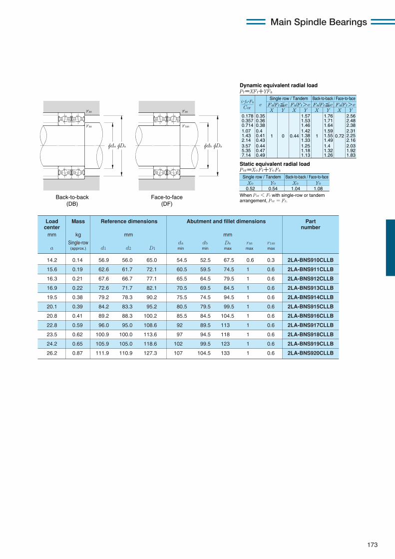
173
Main Spindle Bearings
0.178 0.357 0.714 1.07 1.43 2.14 3.57 5.35 7.14
eX Y
Dynamic equivalent radial loadPr=XFr+YFa
Static equivalent radial loadPor=Xo Fr+Yo Fa
Fa/Fr≦e Fa/Fr>e Fa/Fr≦e Fa/Fr>eX Y X Y X Y
0.35 0.36 0.38 0.4 0.41 0.43 0.44 0.47 0.49
1 0 0.44
1.57 1.53 1.46 1.42 1.38 1.33 1.25 1.18 1.13
1
1.76 1.71 1.64 1.59 1.55 1.49 1.4 1.32 1.26
0.72
2.56 2.48 2.38 2.31 2.25 2.16 2.03 1.92 1.83
When Por < Fr with single-row or tandem arrangement, Por = Fr.
Xo0.52
Yo Xo Yo0.54 1.04 1.08
Cor
i・fo・Fa
Single row / Tandem Back-to-back / Face-to-face
Single row / Tandem Back-to-back / Face-to-face
Back-to-back (DB)
Face-to-face (DF)
φdbφDa
ras
r1as
φdaφDa
ras
ras
14.2 0.14 56.9 56.0 65.0 54.5 52.5 67.5 0.6 0.3 2LA-BNS910CLLB
15.6 0.19 62.6 61.7 72.1 60.5 59.5 74.5 1 0.6 2LA-BNS911CLLB
16.3 0.21 67.6 66.7 77.1 65.5 64.5 79.5 1 0.6 2LA-BNS912CLLB
16.9 0.22 72.6 71.7 82.1 70.5 69.5 84.5 1 0.6 2LA-BNS913CLLB
19.5 0.38 79.2 78.3 90.2 75.5 74.5 94.5 1 0.6 2LA-BNS914CLLB
20.1 0.39 84.2 83.3 95.2 80.5 79.5 99.5 1 0.6 2LA-BNS915CLLB
20.8 0.41 89.2 88.3 100.2 85.5 84.5 104.5 1 0.6 2LA-BNS916CLLB
22.8 0.59 96.0 95.0 108.6 92 89.5 113 1 0.6 2LA-BNS917CLLB
23.5 0.62 100.9 100.0 113.6 97 94.5 118 1 0.6 2LA-BNS918CLLB
24.2 0.65 105.9 105.0 118.6 102 99.5 123 1 0.6 2LA-BNS919CLLB
26.2 0.87 111.9 110.9 127.3 107 104.5 133 1 0.6 2LA-BNS920CLLB
Load Mass Reference dimensions Abutment and fillet dimensions Part center number
mm kg mm mm
Single-row da db Da ras r1asa (approx.) d1 d2 D1 min min max max max

174
Sealed high-speed angular contact ball bearings (steel ball type) 2LA-BNS9 LLB series
Contact angle 20˚ d 50〜100mm
1 Minimum allowable value for corner radius dimension r or r1.
Main Spindle Bearings
φD φd2 φd1φdφD1
B
a
r r
rr1
2LA-BNS910LLB 50 72 12 0.6 0.3 7.90 7.10 805 725 11.9 1 220 23 100
2LA-BNS911LLB 55 80 13 1 0.6 10.1 9.00 1 030 915 15.1 1 540 20 800
2LA-BNS912LLB 60 85 13 1 0.6 10.4 9.70 1 060 990 16.3 1 660 19 400
2LA-BNS913LLB 65 90 13 1 0.6 10.6 10.4 1 080 1 060 17.5 1 790 18 200
2LA-BNS914LLB 70 100 16 1 0.6 13.4 13.1 1 360 1 340 22.1 2 250 16 600
2LA-BNS915LLB 75 105 16 1 0.6 13.7 14.1 1 400 1 430 23.6 2 410 15 600
2LA-BNS916LLB 80 110 16 1 0.6 14.1 15.0 1 440 1 530 25.2 2 570 14 800
2LA-BNS917LLB 85 120 18 1.1 0.6 16.9 17.8 1 730 1 820 29.9 3 050 13 700
2LA-BNS918LLB 90 125 18 1.1 0.6 17.4 19.0 1 770 1 930 32.0 3 250 13 100
2LA-BNS919LLB 95 130 18 1.1 0.6 17.8 20.1 1 820 2 050 34.0 3 450 12 500
2LA-BNS920LLB 100 140 20 1.1 0.6 25.1 27.3 2 560 2 780 46.0 4 700 11 700
Part Boundary dimensions Basic load ratings Static axial Limitingnumber dynamic static dynamic static load capacity speed
mm kN kgf kN kgf min-1
greased D B rs min1 r1s min1 Cr Cor Cr Cor lubrication
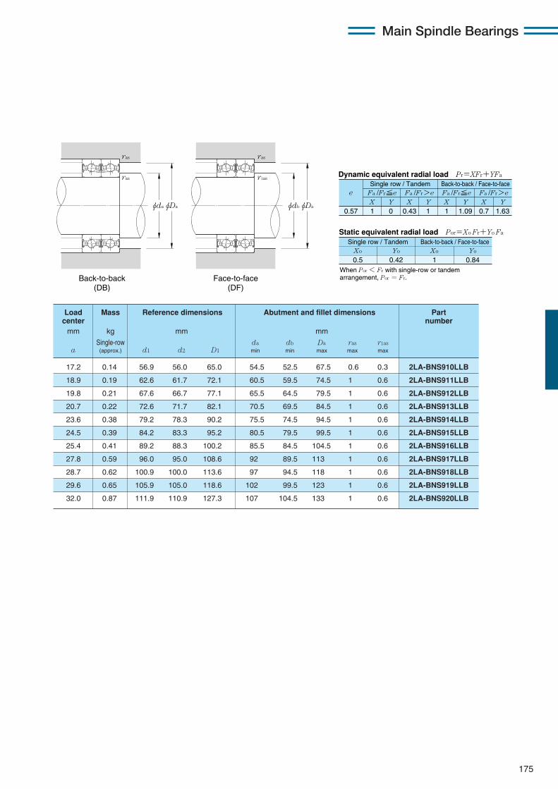
175
Main Spindle Bearings
X Y X Y X Y X Y0.57 1 0 0.43 1 1 1.09 0.7 1.63
Fa /Fr≦e Fa /Fr>e Fa /Fr≦e Fa /Fr>ee
Static equivalent radial load Por=Xo Fr+Yo Fa
When Por < Fr with single-row or tandem arrangement, Por = Fr.
Xo Yo Xo Yo
0.5 0.42 1 0.84
Dynamic equivalent radial load Pr=XFr+YFa
Single row / Tandem Back-to-back / Face-to-face
Single row / Tandem Back-to-back / Face-to-face
17.2 0.14 56.9 56.0 65.0 54.5 52.5 67.5 0.6 0.3 2LA-BNS910LLB
18.9 0.19 62.6 61.7 72.1 60.5 59.5 74.5 1 0.6 2LA-BNS911LLB
19.8 0.21 67.6 66.7 77.1 65.5 64.5 79.5 1 0.6 2LA-BNS912LLB
20.7 0.22 72.6 71.7 82.1 70.5 69.5 84.5 1 0.6 2LA-BNS913LLB
23.6 0.38 79.2 78.3 90.2 75.5 74.5 94.5 1 0.6 2LA-BNS914LLB
24.5 0.39 84.2 83.3 95.2 80.5 79.5 99.5 1 0.6 2LA-BNS915LLB
25.4 0.41 89.2 88.3 100.2 85.5 84.5 104.5 1 0.6 2LA-BNS916LLB
27.8 0.59 96.0 95.0 108.6 92 89.5 113 1 0.6 2LA-BNS917LLB
28.7 0.62 100.9 100.0 113.6 97 94.5 118 1 0.6 2LA-BNS918LLB
29.6 0.65 105.9 105.0 118.6 102 99.5 123 1 0.6 2LA-BNS919LLB
32.0 0.87 111.9 110.9 127.3 107 104.5 133 1 0.6 2LA-BNS920LLB
Load Mass Reference dimensions Abutment and fillet dimensions Partcenter number
mm kg mm mm
Single-row da db Da ras r1asa (approx.) d1 d2 D1 min min max max max
Back-to-back (DB)
Face-to-face (DF)
φdbφDa
ras
r1as
φdaφDa
ras
ras
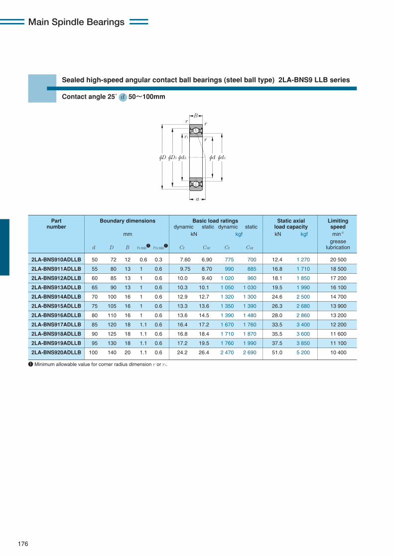
176
Sealed high-speed angular contact ball bearings (steel ball type) 2LA-BNS9 LLB series
Contact angle 25˚ d 50〜100mm
1 Minimum allowable value for corner radius dimension r or r1.
Main Spindle Bearings
φD φd2 φd1φdφD1
B
a
r r
rr1
2LA-BNS910ADLLB 50 72 12 0.6 0.3 7.60 6.90 775 700 12.4 1 270 20 500
2LA-BNS911ADLLB 55 80 13 1 0.6 9.75 8.70 990 885 16.8 1 710 18 500
2LA-BNS912ADLLB 60 85 13 1 0.6 10.0 9.40 1 020 960 18.1 1 850 17 200
2LA-BNS913ADLLB 65 90 13 1 0.6 10.3 10.1 1 050 1 030 19.5 1 990 16 100
2LA-BNS914ADLLB 70 100 16 1 0.6 12.9 12.7 1 320 1 300 24.6 2 500 14 700
2LA-BNS915ADLLB 75 105 16 1 0.6 13.3 13.6 1 350 1 390 26.3 2 680 13 900
2LA-BNS916ADLLB 80 110 16 1 0.6 13.6 14.5 1 390 1 480 28.0 2 860 13 200
2LA-BNS917ADLLB 85 120 18 1.1 0.6 16.4 17.2 1 670 1 760 33.5 3 400 12 200
2LA-BNS918ADLLB 90 125 18 1.1 0.6 16.8 18.4 1 710 1 870 35.5 3 600 11 600
2LA-BNS919ADLLB 95 130 18 1.1 0.6 17.2 19.5 1 760 1 990 37.5 3 850 11 100
2LA-BNS920ADLLB 100 140 20 1.1 0.6 24.2 26.4 2 470 2 690 51.0 5 200 10 400
Part Boundary dimensions Basic load ratings Static axial Limitingnumber dynamic static dynamic static load capacity speed
mm kN kgf kN kgf min-1
greased D B rs min1 r1s min1 Cr Cor Cr Cor lubrication

177
Main Spindle Bearings
X Y X Y X Y X Y0.68 1 0 0.41 0.87 1 0.92 0.67 1.41
Fa /Fr≦e Fa /Fr>e Fa /Fr≦e Fa /Fr>ee
Static equivalent radial load Por=Xo Fr+Yo Fa
When Por < Fr with single-row or tandem arrangement, Por = Fr.
Xo Yo Xo Yo
0.5 0.38 1 0.76
Dynamic equivalent radial load Pr=XFr+YFa
Single row / Tandem Back-to-back / Face-to-face
Single row / Tandem Back-to-back / Face-to-face
20.3 0.14 56.9 56.0 65.0 54.5 52.5 67.5 0.6 0.3 2LA-BNS910ADLLB
22.3 0.19 62.6 61.7 72.1 60.5 59.5 74.5 1 0.6 2LA-BNS911ADLLB
23.5 0.21 67.6 66.7 77.1 65.5 64.5 79.5 1 0.6 2LA-BNS912ADLLB
24.7 0.22 72.6 71.7 82.1 70.5 69.5 84.5 1 0.6 2LA-BNS913ADLLB
27.9 0.38 79.2 78.3 90.2 75.5 74.5 94.5 1 0.6 2LA-BNS914ADLLB
29.1 0.39 84.2 83.3 95.2 80.5 79.5 99.5 1 0.6 2LA-BNS915ADLLB
30.3 0.41 89.2 88.3 100.2 85.5 84.5 104.5 1 0.6 2LA-BNS916ADLLB
33.0 0.59 96.0 95.0 108.6 92 89.5 113 1 0.6 2LA-BNS917ADLLB
34.2 0.62 100.9 100.0 113.6 97 94.5 118 1 0.6 2LA-BNS918ADLLB
35.4 0.65 105.9 105.0 118.6 102 99.5 123 1 0.6 2LA-BNS919ADLLB
38.1 0.87 111.9 110.9 127.3 107 104.5 133 1 0.6 2LA-BNS920ADLLB
Load Mass Reference dimensions Abutment and fillet dimensions Partcenter number
mm kg mm mm
Single-row da db Da ras r1asa (approx.) d1 d2 D1 min min max max max
Back-to-back (DB)
Face-to-face (DF)
φdbφDa
ras
r1as
φdaφDa
ras
ras

Part Boundary dimensions Basic load ratings Static axial Factor Limitingnumber dynamic static dynamic static load capacity speed
mm kN kgf kN kgf min-1
greased D B rs min1 r1s min1 Cr Cor Cr Cor fo lubrication
178
Sealed high-speed angular contact ball bearings (steel ball type) 2LA-BNS0 LLB series
Contact angle 15˚ d 45〜100mm
1 Minimum allowable value for corner radius dimension r or r1.
Main Spindle Bearings
φD φd2 φd1φdφD1
B
a
r r
rr1
2LA-BNS009CLLB 45 75 16 1 0.6 11.8 9.15 1 210 930 13.4 1 370 10.7 22 200
2LA-BNS010CLLB 50 80 16 1 0.6 14.7 11.5 1 500 1 170 16.8 1 720 10.7 20 500
2LA-BNS011CLLB 55 90 18 1.1 0.6 17.3 13.6 1 760 1 380 19.9 2 030 10.6 18 300
2LA-BNS012CLLB 60 95 18 1.1 0.6 18.1 15.0 1 850 1 530 22.0 2 240 10.7 17 200
2LA-BNS013CLLB 65 100 18 1.1 0.6 18.4 15.8 1 870 1 610 23.2 2 360 10.8 16 100
2LA-BNS014CLLB 70 110 20 1.1 0.6 22.4 19.9 2 290 2 030 29.2 2 980 10.8 14 800
2LA-BNS015CLLB 75 115 20 1.1 0.6 23.9 22.4 2 440 2 290 33.0 3 350 10.9 14 000
2LA-BNS016CLLB 80 125 22 1.1 0.6 27.4 25.7 2 790 2 620 38.0 3 850 10.9 13 000
2LA-BNS017CLLB 85 130 22 1.1 0.6 27.7 26.8 2 830 2 740 39.5 4 000 10.9 12 400
2LA-BNS018CLLB 90 140 24 1.5 1 32.0 31.5 3 300 3 200 46.0 4 700 10.9 11 600
2LA-BNS019CLLB 95 145 24 1.5 1 32.5 32.5 3 300 3 350 48.0 4 900 11.0 11 100
2LA-BNS020CLLB 100 150 24 1.5 1 33.5 35.0 3 450 3 600 51.5 5 250 11.0 10 600
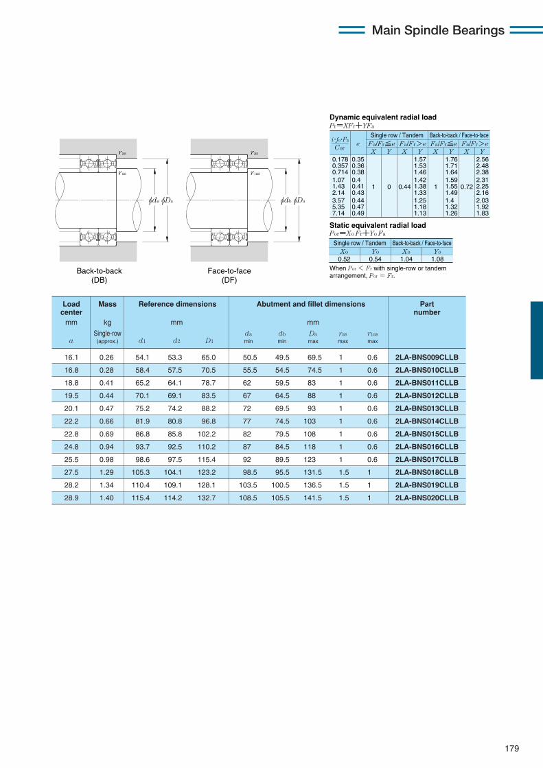
179
Main Spindle Bearings
0.178 0.357 0.714 1.07 1.43 2.14 3.57 5.35 7.14
eX Y
Dynamic equivalent radial loadPr=XFr+YFa
Static equivalent radial loadPor=Xo Fr+Yo Fa
Fa/Fr≦e Fa/Fr>e Fa/Fr≦e Fa/Fr>eX Y X Y X Y
0.35 0.36 0.38 0.4 0.41 0.43 0.44 0.47 0.49
1 0 0.44
1.57 1.53 1.46 1.42 1.38 1.33 1.25 1.18 1.13
1
1.76 1.71 1.64 1.59 1.55 1.49 1.4 1.32 1.26
0.72
2.56 2.48 2.38 2.31 2.25 2.16 2.03 1.92 1.83
When Por < Fr with single-row or tandem arrangement, Por = Fr.
Xo0.52
Yo Xo Yo0.54 1.04 1.08
Cor
i・fo・Fa
Single row / Tandem Back-to-back / Face-to-face
Single row / Tandem Back-to-back / Face-to-face
16.1 0.26 54.1 53.3 65.0 50.5 49.5 69.5 1 0.6 2LA-BNS009CLLB
16.8 0.28 58.4 57.5 70.5 55.5 54.5 74.5 1 0.6 2LA-BNS010CLLB
18.8 0.41 65.2 64.1 78.7 62 59.5 83 1 0.6 2LA-BNS011CLLB
19.5 0.44 70.1 69.1 83.5 67 64.5 88 1 0.6 2LA-BNS012CLLB
20.1 0.47 75.2 74.2 88.2 72 69.5 93 1 0.6 2LA-BNS013CLLB
22.2 0.66 81.9 80.8 96.8 77 74.5 103 1 0.6 2LA-BNS014CLLB
22.8 0.69 86.8 85.8 102.2 82 79.5 108 1 0.6 2LA-BNS015CLLB
24.8 0.94 93.7 92.5 110.2 87 84.5 118 1 0.6 2LA-BNS016CLLB
25.5 0.98 98.6 97.5 115.4 92 89.5 123 1 0.6 2LA-BNS017CLLB
27.5 1.29 105.3 104.1 123.2 98.5 95.5 131.5 1.5 1 2LA-BNS018CLLB
28.2 1.34 110.4 109.1 128.1 103.5 100.5 136.5 1.5 1 2LA-BNS019CLLB
28.9 1.40 115.4 114.2 132.7 108.5 105.5 141.5 1.5 1 2LA-BNS020CLLB
Load Mass Reference dimensions Abutment and fillet dimensions Part center number
mm kg mm mm
Single-row da db Da ras r1asa (approx.) d1 d2 D1 min min max max max
Back-to-back (DB)
Face-to-face (DF)
φdbφDa
ras
r1as
φdaφDa
ras
ras

180
Sealed high-speed angular contact ball bearings (steel ball type) 2LA-BNS0 LLB series
Contact angle 20˚ d 45〜100mm
1 Minimum allowable value for corner radius dimension r or r1.
Main Spindle Bearings
φD φd2 φd1φdφD1
B
a
r r
rr1
2LA-BNS009LLB 45 75 16 1 0.6 11.5 8.95 1 180 910 15.0 1 530 23 500
2LA-BNS010LLB 50 80 16 1 0.6 14.4 11.2 1 470 1 150 18.8 1 920 21 600
2LA-BNS011LLB 55 90 18 1.1 0.6 16.8 13.3 1 720 1 350 22.2 2 260 19 400
2LA-BNS012LLB 60 95 18 1.1 0.6 17.6 14.7 1 800 1 490 24.6 2 500 18 200
2LA-BNS013LLB 65 100 18 1.1 0.6 17.9 15.4 1 830 1 570 25.9 2 640 17 100
2LA-BNS014LLB 70 110 20 1.1 0.6 21.9 19.4 2 230 1 980 32.5 3 300 15 600
2LA-BNS015LLB 75 115 20 1.1 0.6 23.3 21.9 2 380 2 230 36.5 3 750 14 800
2LA-BNS016LLB 80 125 22 1.1 0.6 26.7 25.1 2 720 2 560 42.0 4 300 13 700
2LA-BNS017LLB 85 130 22 1.1 0.6 27.0 26.2 2 760 2 670 44.0 4 500 13 100
2LA-BNS018LLB 90 140 24 1.5 1 31.5 30.5 3 200 3 150 51.5 5 250 12 200
2LA-BNS019LLB 95 145 24 1.5 1 31.5 32.0 3 250 3 250 53.5 5 450 11 700
2LA-BNS020LLB 100 150 24 1.5 1 33.0 34.5 3 350 3 500 57.5 5 850 11 300
Part Boundary dimensions Basic load ratings Static axial Limitingnumber dynamic static dynamic static load capacity speed
mm kN kgf kN kgf min-1
greased D B rs min1 r1s min1 Cr Cor Cr Cor lubrication

181
Main Spindle Bearings
X Y X Y X Y X Y0.57 1 0 0.43 1 1 1.09 0.7 1.63
Fa /Fr≦e Fa /Fr>e Fa /Fr≦e Fa /Fr>ee
Static equivalent radial load Por=Xo Fr+Yo Fa
When Por < Fr with single-row or tandem arrangement, Por = Fr.
Xo Yo Xo Yo
0.5 0.42 1 0.84
Dynamic equivalent radial load Pr=XFr+YFa
Single row / Tandem Back-to-back / Face-to-face
Single row / Tandem Back-to-back / Face-to-face
19.0 0.26 54.1 53.3 65.0 50.5 49.5 69.5 1 0.6 2LA-BNS009LLB
19.9 0.28 58.4 57.5 70.5 55.5 54.5 74.5 1 0.6 2LA-BNS010LLB
22.3 0.41 65.2 64.2 78.7 62 59.5 83 1 0.6 2LA-BNS011LLB
23.2 0.44 70.1 69.2 83.5 67 64.5 88 1 0.6 2LA-BNS012LLB
24.1 0.47 75.2 74.2 88.2 72 69.5 93 1 0.6 2LA-BNS013LLB
26.5 0.66 81.9 80.8 96.8 77 74.5 103 1 0.6 2LA-BNS014LLB
27.4 0.69 86.8 85.8 102.2 82 79.5 108 1 0.6 2LA-BNS015LLB
29.8 0.94 93.7 92.5 110.2 87 84.5 118 1 0.6 2LA-BNS016LLB
30.7 0.98 98.6 97.5 115.4 92 89.5 123 1 0.6 2LA-BNS017LLB
33.1 1.29 105.3 104.2 123.2 98.5 95.5 131.5 1.5 1 2LA-BNS018LLB
34.0 1.34 110.4 109.2 128.1 103.5 100.5 136.5 1.5 1 2LA-BNS019LLB
34.9 1.40 115.4 114.2 132.7 108.5 105.5 141.5 1.5 1 2LA-BNS020LLB
Load Mass Reference dimensions Abutment and fillet dimensions Partcenter number
mm kg mm mm
Single-row da db Da ras r1asa (approx.) d1 d2 D1 min min max max max
Back-to-back (DB)
Face-to-face (DF)
φdbφDa
ras
r1as
φdaφDa
ras
ras

182
Sealed high-speed angular contact ball bearings (steel ball type) 2LA-BNS0 LLB series
Contact angle 25˚ d 45〜100mm
1 Minimum allowable value for corner radius dimension r or r1.
Main Spindle Bearings
φD φd2 φd1φdφD1
B
a
r r
rr1
2LA-BNS009ADLLB 45 75 16 1 0.6 11.2 8.65 1 140 885 16.7 1 700 20 800
2LA-BNS010ADLLB 50 80 16 1 0.6 13.9 10.9 1 420 1 110 21.0 2 140 19 200
2LA-BNS011ADLLB 55 90 18 1.1 0.6 16.3 12.9 1 660 1 310 24.8 2 530 17 200
2LA-BNS012ADLLB 60 95 18 1.1 0.6 17.1 14.2 1 740 1 450 27.4 2 800 16 100
2LA-BNS013ADLLB 65 100 18 1.1 0.6 17.3 14.9 1 770 1 520 28.9 2 940 15 200
2LA-BNS014ADLLB 70 110 20 1.1 0.6 21.2 18.8 2 160 1 920 36.5 3 700 13 900
2LA-BNS015ADLLB 75 115 20 1.1 0.6 22.5 21.2 2 300 2 160 41.0 4 200 13 200
2LA-BNS016ADLLB 80 125 22 1.1 0.6 25.8 24.3 2 630 2 480 47.0 4 800 12 200
2LA-BNS017ADLLB 85 130 22 1.1 0.6 26.1 25.4 2 670 2 590 49.0 5 000 11 600
2LA-BNS018ADLLB 90 140 24 1.5 1 30.5 29.7 3 100 3 050 57.5 5 850 10 900
2LA-BNS019ADLLB 95 145 24 1.5 1 30.5 31.0 3 150 3 150 60.0 6 100 10 400
2LA-BNS020ADLLB 100 150 24 1.5 1 32.0 33.0 3 250 3 400 64.0 6 550 10 000
Part Boundary dimensions Basic load ratings Static axial Limitingnumber dynamic static dynamic static load capacity speed
mm kN kgf kN kgf min-1
greased D B rs min1 r1s min1 Cr Cor Cr Cor lubrication

183
Main Spindle Bearings
22.1 0.26 54.1 53.3 65.0 50.5 49.5 69.5 1 0.6 2LA-BNS009ADLLB
23.3 0.28 58.4 57.6 70.5 55.5 54.5 74.5 1 0.6 2LA-BNS010ADLLB
26.0 0.41 65.2 64.2 78.7 62 59.5 83 1 0.6 2LA-BNS011ADLLB
27.2 0.44 70.1 69.2 83.5 67 64.5 88 1 0.6 2LA-BNS012ADLLB
28.4 0.47 75.2 74.2 88.2 72 69.5 93 1 0.6 2LA-BNS013ADLLB
31.1 0.66 81.9 80.9 96.8 77 74.5 103 1 0.6 2LA-BNS014ADLLB
32.3 0.69 86.8 85.9 102.2 82 79.5 108 1 0.6 2LA-BNS015ADLLB
35.1 0.94 93.7 92.6 110.2 87 84.5 118 1 0.6 2LA-BNS016ADLLB
36.2 0.98 98.6 97.6 115.4 92 89.5 123 1 0.6 2LA-BNS017ADLLB
39.0 1.29 105.3 104.2 123.2 98.5 95.5 131.5 1.5 1 2LA-BNS018ADLLB
40.2 1.34 110.4 109.2 128.1 103.5 100.5 136.5 1.5 1 2LA-BNS019ADLLB
41.3 1.40 115.4 114.2 132.7 108.5 105.5 141.5 1.5 1 2LA-BNS020ADLLB
Load Mass Reference dimensions Abutment and fillet dimensions Partcenter number
mm kg mm mm
Single-row da db Da ras r1asa (approx.) d1 d2 D1 min min max max max
X Y X Y X Y X Y0.68 1 0 0.41 0.87 1 0.92 0.67 1.41
Fa /Fr≦e Fa /Fr>e Fa /Fr≦e Fa /Fr>ee
Static equivalent radial load Por=Xo Fr+Yo Fa
When Por < Fr with single-row or tandem arrangement, Por = Fr.
Xo Yo Xo Yo
0.5 0.38 1 0.76
Dynamic equivalent radial load Pr=XFr+YFa
Single row / Tandem Back-to-back / Face-to-face
Single row / Tandem Back-to-back / Face-to-face
Back-to-back (DB)
Face-to-face (DF)
φdbφDa
ras
r1as
φdaφDa
ras
ras
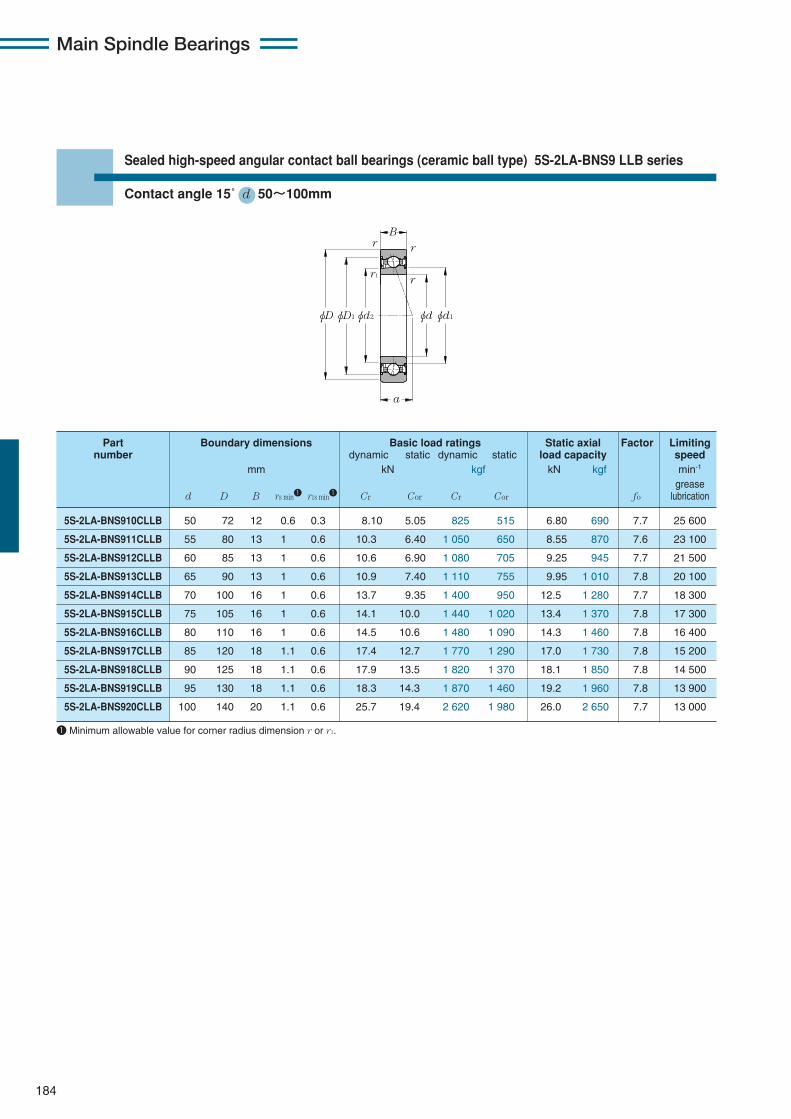
Part Boundary dimensions Basic load ratings Static axial Factor Limitingnumber dynamic static dynamic static load capacity speed
mm kN kgf kN kgf min-1
greased D B rs min1 r1s min1 Cr Cor Cr Cor fo lubrication
184
Sealed high-speed angular contact ball bearings (ceramic ball type) 5S-2LA-BNS9 LLB series
Contact angle 15˚ d 50〜100mm
1 Minimum allowable value for corner radius dimension r or r1.
Main Spindle Bearings
φD φd2 φd1φdφD1
B
a
r r
rr1
5S-2LA-BNS910CLLB 50 72 12 0.6 0.3 8.10 5.05 825 515 6.80 690 7.7 25 600
5S-2LA-BNS911CLLB 55 80 13 1 0.6 10.3 6.40 1 050 650 8.55 870 7.6 23 100
5S-2LA-BNS912CLLB 60 85 13 1 0.6 10.6 6.90 1 080 705 9.25 945 7.7 21 500
5S-2LA-BNS913CLLB 65 90 13 1 0.6 10.9 7.40 1 110 755 9.95 1 010 7.8 20 100
5S-2LA-BNS914CLLB 70 100 16 1 0.6 13.7 9.35 1 400 950 12.5 1 280 7.7 18 300
5S-2LA-BNS915CLLB 75 105 16 1 0.6 14.1 10.0 1 440 1 020 13.4 1 370 7.8 17 300
5S-2LA-BNS916CLLB 80 110 16 1 0.6 14.5 10.6 1 480 1 090 14.3 1 460 7.8 16 400
5S-2LA-BNS917CLLB 85 120 18 1.1 0.6 17.4 12.7 1 770 1 290 17.0 1 730 7.8 15 200
5S-2LA-BNS918CLLB 90 125 18 1.1 0.6 17.9 13.5 1 820 1 370 18.1 1 850 7.8 14 500
5S-2LA-BNS919CLLB 95 130 18 1.1 0.6 18.3 14.3 1 870 1 460 19.2 1 960 7.8 13 900
5S-2LA-BNS920CLLB 100 140 20 1.1 0.6 25.7 19.4 2 620 1 980 26.0 2 650 7.7 13 000

185
Main Spindle Bearings
14.2 0.14 56.9 56.0 65.0 54.5 52.5 67.5 0.6 0.3 5S-2LA-BNS910CLLB
15.6 0.18 62.6 61.7 72.1 60.5 59.5 74.5 1 0.6 5S-2LA-BNS911CLLB
16.3 0.20 67.6 66.7 77.1 65.5 64.5 79.5 1 0.6 5S-2LA-BNS912CLLB
16.9 0.21 72.6 71.7 82.1 70.5 69.5 84.5 1 0.6 5S-2LA-BNS913CLLB
19.5 0.36 79.2 78.3 90.2 75.5 74.5 94.5 1 0.6 5S-2LA-BNS914CLLB
20.1 0.37 84.2 83.3 95.2 80.5 79.5 99.5 1 0.6 5S-2LA-BNS915CLLB
20.8 0.39 89.2 88.3 100.2 85.5 84.5 104.5 1 0.6 5S-2LA-BNS916CLLB
22.8 0.57 96.0 95.0 108.6 92 89.5 113 1 0.6 5S-2LA-BNS917CLLB
23.5 0.59 100.9 100.0 113.6 97 94.5 118 1 0.6 5S-2LA-BNS918CLLB
24.2 0.62 105.9 105.0 118.6 102 99.5 123 1 0.6 5S-2LA-BNS919CLLB
26.2 0.82 111.9 110.9 127.3 107 104.5 133 1 0.6 5S-2LA-BNS920CLLB
Load Mass Reference dimensions Abutment and fillet dimensions Partcenter number
mm kg mm mm
Single-row da db Da ras r1asa (approx.) d1 d2 D1 min min max max max
0.178 0.357 0.714 1.07 1.43 2.14 3.57 5.35 7.14
eX Y
Dynamic equivalent radial loadPr=XFr+YFa
Static equivalent radial loadPor=Xo Fr+Yo Fa
Fa/Fr≦e Fa/Fr>e Fa/Fr≦e Fa/Fr>eX Y X Y X Y
0.35 0.36 0.38 0.4 0.41 0.43 0.44 0.47 0.49
1 0 0.44
1.57 1.53 1.46 1.42 1.38 1.33 1.25 1.18 1.13
1
1.76 1.71 1.64 1.59 1.55 1.49 1.4 1.32 1.26
0.72
2.56 2.48 2.38 2.31 2.25 2.16 2.03 1.92 1.83
When Por < Fr with single-row or tandem arrangement, Por = Fr.
Xo0.52
Yo Xo Yo0.54 1.04 1.08
Cor
i・fo・Fa
Single row / Tandem Back-to-back / Face-to-face
Single row / Tandem Back-to-back / Face-to-face
Back-to-back (DB)
Face-to-face (DF)
φdbφDa
ras
r1as
φdaφDa
ras
ras

186
Sealed high-speed angular contact ball bearings (ceramic ball type) 5S-2LA-BNS9 LLB series
Contact angle 20˚ d 50〜100mm
1 Minimum allowable value for corner radius dimension r or r1.
Main Spindle Bearings
φD φd2 φd1φdφD1
B
a
r r
rr1
5S-2LA-BNS910LLB 50 72 12 0.6 0.3 7.90 4.95 805 505 7.75 790 28 200
5S-2LA-BNS911LLB 55 80 13 1 0.6 10.1 6.25 1 030 635 9.75 995 25 500
5S-2LA-BNS912LLB 60 85 13 1 0.6 10.4 6.70 1 060 685 10.5 1 080 23 700
5S-2LA-BNS913LLB 65 90 13 1 0.6 10.6 7.20 1 080 735 11.3 1 160 22 200
5S-2LA-BNS914LLB 70 100 16 1 0.6 13.4 9.10 1 360 930 14.3 1 460 20 200
5S-2LA-BNS915LLB 75 105 16 1 0.6 13.7 9.75 1 400 995 15.3 1 560 19 100
5S-2LA-BNS916LLB 80 110 16 1 0.6 14.1 10.4 1 440 1 060 16.3 1 660 18 100
5S-2LA-BNS917LLB 85 120 18 1.1 0.6 16.9 12.3 1 730 1 260 19.4 1 980 16 800
5S-2LA-BNS918LLB 90 125 18 1.1 0.6 17.4 13.1 1 770 1 340 20.6 2 100 16 000
5S-2LA-BNS919LLB 95 130 18 1.1 0.6 17.8 14.0 1 820 1 420 21.9 2 230 15 300
5S-2LA-BNS920LLB 100 140 20 1.1 0.6 25.1 18.9 2 560 1 930 29.7 3 050 14 300
Part Boundary dimensions Basic load ratings Static axial Limitingnumber dynamic static dynamic static load capacity speed
mm kN kgf kN kgf min-1
greased D B rs min1 r1s min1 Cr Cor Cr Cor lubrication
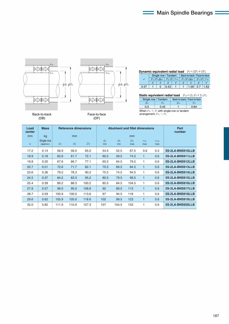
Load Mass Reference dimensions Abutment and fillet dimensions Partcenter number
mm kg mm mm
Single-row da db Da ras r1asa (approx.) d1 d2 D1 min min max max max
187
Main Spindle Bearings
17.2 0.14 56.9 56.0 65.0 54.5 52.5 67.5 0.6 0.3 5S-2LA-BNS910LLB
18.9 0.18 62.6 61.7 72.1 60.5 59.5 74.5 1 0.6 5S-2LA-BNS911LLB
19.8 0.20 67.6 66.7 77.1 65.5 64.5 79.5 1 0.6 5S-2LA-BNS912LLB
20.7 0.21 72.6 71.7 82.1 70.5 69.5 84.5 1 0.6 5S-2LA-BNS913LLB
23.6 0.36 79.2 78.3 90.2 75.5 74.5 94.5 1 0.6 5S-2LA-BNS914LLB
24.5 0.37 84.2 83.3 95.2 80.5 79.5 99.5 1 0.6 5S-2LA-BNS915LLB
25.4 0.39 89.2 88.3 100.2 85.5 84.5 104.5 1 0.6 5S-2LA-BNS916LLB
27.8 0.57 96.0 95.0 108.6 92 89.5 113 1 0.6 5S-2LA-BNS917LLB
28.7 0.59 100.9 100.0 113.6 97 94.5 118 1 0.6 5S-2LA-BNS918LLB
29.6 0.62 105.9 105.0 118.6 102 99.5 123 1 0.6 5S-2LA-BNS919LLB
32.0 0.82 111.9 110.9 127.3 107 104.5 133 1 0.6 5S-2LA-BNS920LLB
X Y X Y X Y X Y0.57 1 0 0.43 1 1 1.09 0.7 1.63
Fa /Fr≦e Fa /Fr>e Fa /Fr≦e Fa /Fr>ee
Static equivalent radial load Por=Xo Fr+Yo Fa
When Por < Fr with single-row or tandem arrangement, Por = Fr.
Xo Yo Xo Yo
0.5 0.42 1 0.84
Dynamic equivalent radial load Pr=XFr+YFa
Single row / Tandem Back-to-back / Face-to-face
Single row / Tandem Back-to-back / Face-to-face
Back-to-back (DB)
Face-to-face (DF)
φdbφDa
ras
r1as
φdaφDa
ras
ras

188
Sealed high-speed angular contact ball bearings (ceramic ball type) 5S-2LA-BNS9 LLB series
Contact angle 25˚ d 50〜100mm
1 Minimum allowable value for corner radius dimension r or r1.
Main Spindle Bearings
φD φd2 φd1φdφD1
B
a
r r
rr1
5S-2LA-BNS910ADLLB 50 72 12 0.6 0.3 7.60 4.75 775 485 8.80 895 25 600
5S-2LA-BNS911ADLLB 55 80 13 1 0.6 9.75 6.05 990 615 11.1 1 130 23 200
5S-2LA-BNS912ADLLB 60 85 13 1 0.6 10.0 6.50 1 020 665 12.0 1 220 21 600
5S-2LA-BNS913ADLLB 65 90 13 1 0.6 10.3 7.00 1 050 715 12.9 1 310 20 200
5S-2LA-BNS914ADLLB 70 100 16 1 0.6 12.9 8.80 1 320 900 16.2 1 650 18 400
5S-2LA-BNS915ADLLB 75 105 16 1 0.6 13.3 9.45 1 350 960 17.3 1 770 17 400
5S-2LA-BNS916ADLLB 80 110 16 1 0.6 13.6 10.0 1 390 1 020 18.5 1 890 16 500
5S-2LA-BNS917ADLLB 85 120 18 1.1 0.6 16.4 11.9 1 670 1 220 22.0 2 240 15 300
5S-2LA-BNS918ADLLB 90 125 18 1.1 0.6 16.8 12.7 1 710 1 300 23.4 2 390 14 500
5S-2LA-BNS919ADLLB 95 130 18 1.1 0.6 17.2 13.5 1 760 1 380 24.8 2 530 13 900
5S-2LA-BNS920ADLLB 100 140 20 1.1 0.6 24.2 18.3 2 470 1 870 33.5 3 450 13 000
Part Boundary dimensions Basic load ratings Static axial Limitingnumber dynamic static dynamic static load capacity speed
mm kN kgf kN kgf min-1
greased D B rs min1 r1s min1 Cr Cor Cr Cor lubrication

189
Main Spindle Bearings
20.3 0.14 56.9 56.0 65.0 54.5 52.5 67.5 0.6 0.3 5S-2LA-BNS910ADLLB
22.3 0.18 62.6 61.7 72.1 60.5 59.5 74.5 1 0.6 5S-2LA-BNS911ADLLB
23.5 0.20 67.6 66.7 77.1 65.5 64.5 79.5 1 0.6 5S-2LA-BNS912ADLLB
24.7 0.21 72.6 71.7 82.1 70.5 69.5 84.5 1 0.6 5S-2LA-BNS913ADLLB
27.9 0.36 79.2 78.3 90.2 75.5 74.5 94.5 1 0.6 5S-2LA-BNS914ADLLB
29.1 0.37 84.2 83.3 95.2 80.5 79.5 99.5 1 0.6 5S-2LA-BNS915ADLLB
30.3 0.39 89.2 88.3 100.2 85.5 84.5 104.5 1 0.6 5S-2LA-BNS916ADLLB
33.0 0.57 96.0 95.0 108.6 92 89.5 113 1 0.6 5S-2LA-BNS917ADLLB
34.2 0.59 100.9 100.0 113.6 97 94.5 118 1 0.6 5S-2LA-BNS918ADLLB
35.4 0.62 105.9 105.0 118.6 102 99.5 123 1 0.6 5S-2LA-BNS919ADLLB
38.1 0.82 111.9 110.9 127.3 107 104.5 133 1 0.6 5S-2LA-BNS920ADLLB
Load Mass Reference dimensions Abutment and fillet dimensions Partcenter number
mm kg mm mm
Single-row da db Da ras r1asa (approx.) d1 d2 D1 min min max max max
X Y X Y X Y X Y0.68 1 0 0.41 0.87 1 0.92 0.67 1.41
Fa /Fr≦e Fa /Fr>e Fa /Fr≦e Fa /Fr>ee
Static equivalent radial load Por=Xo Fr+Yo Fa
When Por < Fr with single-row or tandem arrangement, Por = Fr.
Xo Yo Xo Yo
0.5 0.38 1 0.76
Dynamic equivalent radial load Pr=XFr+YFa
Single row / Tandem Back-to-back / Face-to-face
Single row / Tandem Back-to-back / Face-to-face
Back-to-back (DB)
Face-to-face (DF)
φdbφDa
ras
r1as
φdaφDa
ras
ras
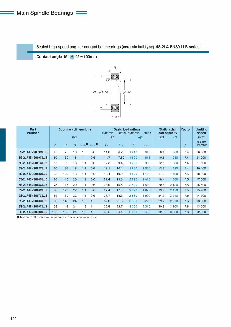
Part Boundary dimensions Basic load ratings Static axial Factor Limitingnumber dynamic static dynamic static load capacity speed
mm kN kgf kN kgf min-1
greased D B rs min1 r1s min1 Cr Cor Cr Cor fo lubrication
190
Sealed high-speed angular contact ball bearings (ceramic ball type) 5S-2LA-BNS0 LLB series
Contact angle 15˚ d 45〜100mm
1 Minimum allowable value for corner radius dimension r or r1.
Main Spindle Bearings
φD φd2 φd1φdφD1
B
a
r r
rr1
5S-2LA-BNS009CLLB 45 75 16 1 0.6 11.8 6.20 1 210 645 8.45 860 7.4 26 000
5S-2LA-BNS010CLLB 50 80 16 1 0.6 14.7 7.50 1 500 815 10.6 1 080 7.4 24 000
5S-2LA-BNS011CLLB 55 90 18 1.1 0.6 17.3 9.40 1 760 960 12.5 1 280 7.4 21 500
5S-2LA-BNS012CLLB 60 95 18 1.1 0.6 18.1 10.4 1 850 1 060 13.9 1 420 7.4 20 100
5S-2LA-BNS013CLLB 65 100 18 1.1 0.6 18.4 10.9 1 870 1 120 14.6 1 490 7.5 18 900
5S-2LA-BNS014CLLB 70 110 20 1.1 0.6 22.4 13.8 2 290 1 410 18.4 1 880 7.5 17 300
5S-2LA-BNS015CLLB 75 115 20 1.1 0.6 23.9 15.5 2 440 1 590 20.8 2 120 7.5 16 400
5S-2LA-BNS016CLLB 80 125 22 1.1 0.6 27.4 17.8 2 790 1 820 23.8 2 430 7.5 15 200
5S-2LA-BNS017CLLB 85 130 22 1.1 0.6 27.7 18.6 2 830 1 900 24.9 2 540 7.6 14 500
5S-2LA-BNS018CLLB 90 140 24 1.5 1 32.0 21.8 3 300 2 220 29.2 2 970 7.6 13 600
5S-2LA-BNS019CLLB 95 145 24 1.5 1 32.5 22.7 3 300 2 310 30.5 3 100 7.6 13 000
5S-2LA-BNS020CLLB 100 150 24 1.5 1 33.5 24.4 3 450 2 480 32.5 3 350 7.6 12 500
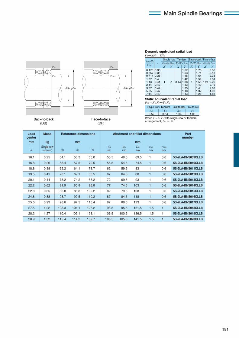
191
Main Spindle Bearings
16.1 0.25 54.1 53.3 65.0 50.5 49.5 69.5 1 0.6 5S-2LA-BNS009CLLB
16.8 0.26 58.4 57.5 70.5 55.5 54.5 74.5 1 0.6 5S-2LA-BNS010CLLB
18.8 0.38 65.2 64.1 78.7 62 59.5 83 1 0.6 5S-2LA-BNS011CLLB
19.5 0.41 70.1 69.1 83.5 67 64.5 88 1 0.6 5S-2LA-BNS012CLLB
20.1 0.44 75.2 74.2 88.2 72 69.5 93 1 0.6 5S-2LA-BNS013CLLB
22.2 0.62 81.9 80.8 96.8 77 74.5 103 1 0.6 5S-2LA-BNS014CLLB
22.8 0.65 86.8 85.8 102.2 82 79.5 108 1 0.6 5S-2LA-BNS015CLLB
24.8 0.88 93.7 92.5 110.2 87 84.5 118 1 0.6 5S-2LA-BNS016CLLB
25.5 0.93 98.6 97.5 115.4 92 89.5 123 1 0.6 5S-2LA-BNS017CLLB
27.5 1.22 105.3 104.1 123.2 98.5 95.5 131.5 1.5 1 5S-2LA-BNS018CLLB
28.2 1.27 110.4 109.1 128.1 103.5 100.5 136.5 1.5 1 5S-2LA-BNS019CLLB
28.9 1.32 115.4 114.2 132.7 108.5 105.5 141.5 1.5 1 5S-2LA-BNS020CLLB
Load Mass Reference dimensions Abutment and fillet dimensions Partcenter number
mm kg mm mm
Single-row da db Da ras r1asa (approx.) d1 d2 D1 min min max max max
0.178 0.357 0.714 1.07 1.43 2.14 3.57 5.35 7.14
eX Y
Dynamic equivalent radial loadPr=XFr+YFa
Static equivalent radial loadPor=Xo Fr+Yo Fa
Fa/Fr≦e Fa/Fr>e Fa/Fr≦e Fa/Fr>eX Y X Y X Y
0.35 0.36 0.38 0.4 0.41 0.43 0.44 0.47 0.49
1 0 0.44
1.57 1.53 1.46 1.42 1.38 1.33 1.25 1.18 1.13
1
1.76 1.71 1.64 1.59 1.55 1.49 1.4 1.32 1.26
0.72
2.56 2.48 2.38 2.31 2.25 2.16 2.03 1.92 1.83
When Por < Fr with single-row or tandem arrangement, Por = Fr.
Xo0.52
Yo Xo Yo0.54 1.04 1.08
Cor
i・fo・Fa
Single row / Tandem Back-to-back / Face-to-face
Single row / Tandem Back-to-back / Face-to-face
Back-to-back (DB)
Face-to-face (DF)
φdbφDa
ras
r1as
φdaφDa
ras
ras

192
Sealed high-speed angular contact ball bearings (ceramic ball type) 5S-2LA-BNS0 LLB series
Contact angle 20˚ d 45〜100mm
1 Minimum allowable value for corner radius dimension r or r1.
Main Spindle Bearings
φD φd2 φd1φdφD1
B
a
r r
rr1
5S-2LA-BNS009LLB 45 75 16 1 0.6 11.5 6.2 1 180 630 9.70 985 28 700
5S-2LA-BNS010LLB 50 80 16 1 0.6 14.4 7.8 1 470 795 12.2 1 240 26 500
5S-2LA-BNS011LLB 55 90 18 1.1 0.6 16.8 9.2 1 720 935 14.4 1 460 23 700
5S-2LA-BNS012LLB 60 95 18 1.1 0.6 17.6 10.2 1 800 1 040 15.9 1 620 22 200
5S-2LA-BNS013LLB 65 100 18 1.1 0.6 17.9 10.7 1 830 1 090 16.7 1 710 20 800
5S-2LA-BNS014LLB 70 110 20 1.1 0.6 21.9 13.5 2 230 1 370 21.1 2 150 19 100
5S-2LA-BNS015LLB 75 115 20 1.1 0.6 23.3 15.2 2 380 1 550 23.8 2 420 18 100
5S-2LA-BNS016LLB 80 125 22 1.1 0.6 26.7 17.4 2 720 1 770 27.2 2 780 16 800
5S-2LA-BNS017LLB 85 130 22 1.1 0.6 27.0 18.1 2 760 1 850 28.4 2 900 16 000
5S-2LA-BNS018LLB 90 140 24 1.5 1 31.5 21.3 3 200 2 170 33.5 3 400 15 000
5S-2LA-BNS019LLB 95 145 24 1.5 1 31.5 22.1 3 250 2 260 34.5 3 550 14 300
5S-2LA-BNS020LLB 100 150 24 1.5 1 33.0 23.8 3 350 2 420 37.5 3 800 13 800
Part Boundary dimensions Basic load ratings Static axial Limitingnumber dynamic static dynamic static load capacity speed
mm kN kgf kN kgf min-1
greased D B rs min1 r1s min1 Cr Cor Cr Cor lubrication
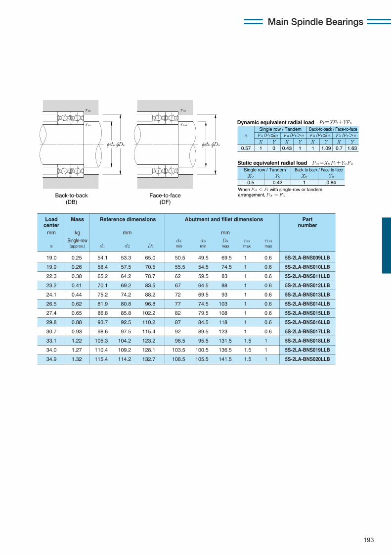
193
Main Spindle Bearings
19.0 0.25 54.1 53.3 65.0 50.5 49.5 69.5 1 0.6 5S-2LA-BNS009LLB
19.9 0.26 58.4 57.5 70.5 55.5 54.5 74.5 1 0.6 5S-2LA-BNS010LLB
22.3 0.38 65.2 64.2 78.7 62 59.5 83 1 0.6 5S-2LA-BNS011LLB
23.2 0.41 70.1 69.2 83.5 67 64.5 88 1 0.6 5S-2LA-BNS012LLB
24.1 0.44 75.2 74.2 88.2 72 69.5 93 1 0.6 5S-2LA-BNS013LLB
26.5 0.62 81.9 80.8 96.8 77 74.5 103 1 0.6 5S-2LA-BNS014LLB
27.4 0.65 86.8 85.8 102.2 82 79.5 108 1 0.6 5S-2LA-BNS015LLB
29.8 0.88 93.7 92.5 110.2 87 84.5 118 1 0.6 5S-2LA-BNS016LLB
30.7 0.93 98.6 97.5 115.4 92 89.5 123 1 0.6 5S-2LA-BNS017LLB
33.1 1.22 105.3 104.2 123.2 98.5 95.5 131.5 1.5 1 5S-2LA-BNS018LLB
34.0 1.27 110.4 109.2 128.1 103.5 100.5 136.5 1.5 1 5S-2LA-BNS019LLB
34.9 1.32 115.4 114.2 132.7 108.5 105.5 141.5 1.5 1 5S-2LA-BNS020LLB
Load Mass Reference dimensions Abutment and fillet dimensions Partcenter number
mm kg mm mm
Single-row da db Da ras r1asa (approx.) d1 d2 D1 min min max max max
X Y X Y X Y X Y0.57 1 0 0.43 1 1 1.09 0.7 1.63
Fa /Fr≦e Fa /Fr>e Fa /Fr≦e Fa /Fr>ee
Static equivalent radial load Por=Xo Fr+Yo Fa
When Por < Fr with single-row or tandem arrangement, Por = Fr.
Xo Yo Xo Yo
0.5 0.42 1 0.84
Dynamic equivalent radial load Pr=XFr+YFa
Single row / Tandem Back-to-back / Face-to-face
Single row / Tandem Back-to-back / Face-to-face
Back-to-back (DB)
Face-to-face (DF)
φdbφDa
ras
r1as
φdaφDa
ras
ras
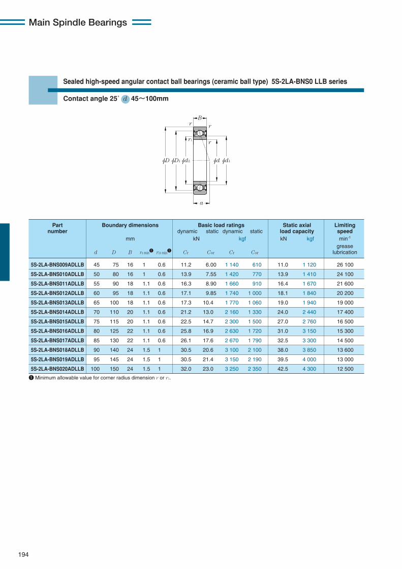
194
Sealed high-speed angular contact ball bearings (ceramic ball type) 5S-2LA-BNS0 LLB series
Contact angle 25˚ d 45〜100mm
1 Minimum allowable value for corner radius dimension r or r1.
Main Spindle Bearings
φD φd2 φd1φdφD1
B
a
r r
rr1
5S-2LA-BNS009ADLLB 45 75 16 1 0.6 11.2 6.00 1 140 610 11.0 1 120 26 100
5S-2LA-BNS010ADLLB 50 80 16 1 0.6 13.9 7.55 1 420 770 13.9 1 410 24 100
5S-2LA-BNS011ADLLB 55 90 18 1.1 0.6 16.3 8.90 1 660 910 16.4 1 670 21 600
5S-2LA-BNS012ADLLB 60 95 18 1.1 0.6 17.1 9.85 1 740 1 000 18.1 1 840 20 200
5S-2LA-BNS013ADLLB 65 100 18 1.1 0.6 17.3 10.4 1 770 1 060 19.0 1 940 19 000
5S-2LA-BNS014ADLLB 70 110 20 1.1 0.6 21.2 13.0 2 160 1 330 24.0 2 440 17 400
5S-2LA-BNS015ADLLB 75 115 20 1.1 0.6 22.5 14.7 2 300 1 500 27.0 2 760 16 500
5S-2LA-BNS016ADLLB 80 125 22 1.1 0.6 25.8 16.9 2 630 1 720 31.0 3 150 15 300
5S-2LA-BNS017ADLLB 85 130 22 1.1 0.6 26.1 17.6 2 670 1 790 32.5 3 300 14 500
5S-2LA-BNS018ADLLB 90 140 24 1.5 1 30.5 20.6 3 100 2 100 38.0 3 850 13 600
5S-2LA-BNS019ADLLB 95 145 24 1.5 1 30.5 21.4 3 150 2 190 39.5 4 000 13 000
5S-2LA-BNS020ADLLB 100 150 24 1.5 1 32.0 23.0 3 250 2 350 42.5 4 300 12 500
Part Boundary dimensions Basic load ratings Static axial Limitingnumber dynamic static dynamic static load capacity speed
mm kN kgf kN kgf min-1
greased D B rs min1 r1s min1 Cr Cor Cr Cor lubrication
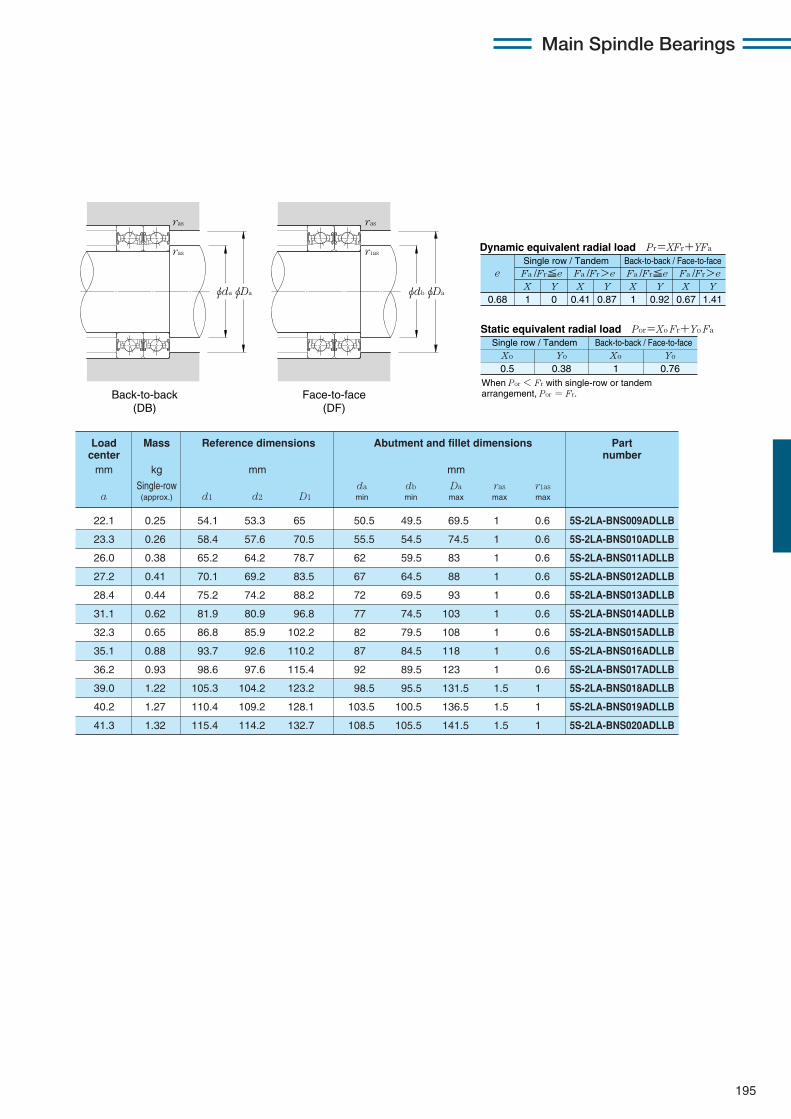
195
Main Spindle Bearings
22.1 0.25 54.1 53.3 65 50.5 49.5 69.5 1 0.6 5S-2LA-BNS009ADLLB
23.3 0.26 58.4 57.6 70.5 55.5 54.5 74.5 1 0.6 5S-2LA-BNS010ADLLB
26.0 0.38 65.2 64.2 78.7 62 59.5 83 1 0.6 5S-2LA-BNS011ADLLB
27.2 0.41 70.1 69.2 83.5 67 64.5 88 1 0.6 5S-2LA-BNS012ADLLB
28.4 0.44 75.2 74.2 88.2 72 69.5 93 1 0.6 5S-2LA-BNS013ADLLB
31.1 0.62 81.9 80.9 96.8 77 74.5 103 1 0.6 5S-2LA-BNS014ADLLB
32.3 0.65 86.8 85.9 102.2 82 79.5 108 1 0.6 5S-2LA-BNS015ADLLB
35.1 0.88 93.7 92.6 110.2 87 84.5 118 1 0.6 5S-2LA-BNS016ADLLB
36.2 0.93 98.6 97.6 115.4 92 89.5 123 1 0.6 5S-2LA-BNS017ADLLB
39.0 1.22 105.3 104.2 123.2 98.5 95.5 131.5 1.5 1 5S-2LA-BNS018ADLLB
40.2 1.27 110.4 109.2 128.1 103.5 100.5 136.5 1.5 1 5S-2LA-BNS019ADLLB
41.3 1.32 115.4 114.2 132.7 108.5 105.5 141.5 1.5 1 5S-2LA-BNS020ADLLB
Load Mass Reference dimensions Abutment and fillet dimensions Partcenter number
mm kg mm mm
Single-row da db Da ras r1asa (approx.) d1 d2 D1 min min max max max
X Y X Y X Y X Y0.68 1 0 0.41 0.87 1 0.92 0.67 1.41
Fa /Fr≦e Fa /Fr>e Fa /Fr≦e Fa /Fr>ee
Static equivalent radial load Por=Xo Fr+Yo Fa
When Por < Fr with single-row or tandem arrangement, Por = Fr.
Xo Yo Xo Yo
0.5 0.38 1 0.76
Dynamic equivalent radial load Pr=XFr+YFa
Single row / Tandem Back-to-back / Face-to-face
Single row / Tandem Back-to-back / Face-to-face
Back-to-back (DB)
Face-to-face (DF)
φdbφDa
ras
r1as
φdaφDa
ras
ras
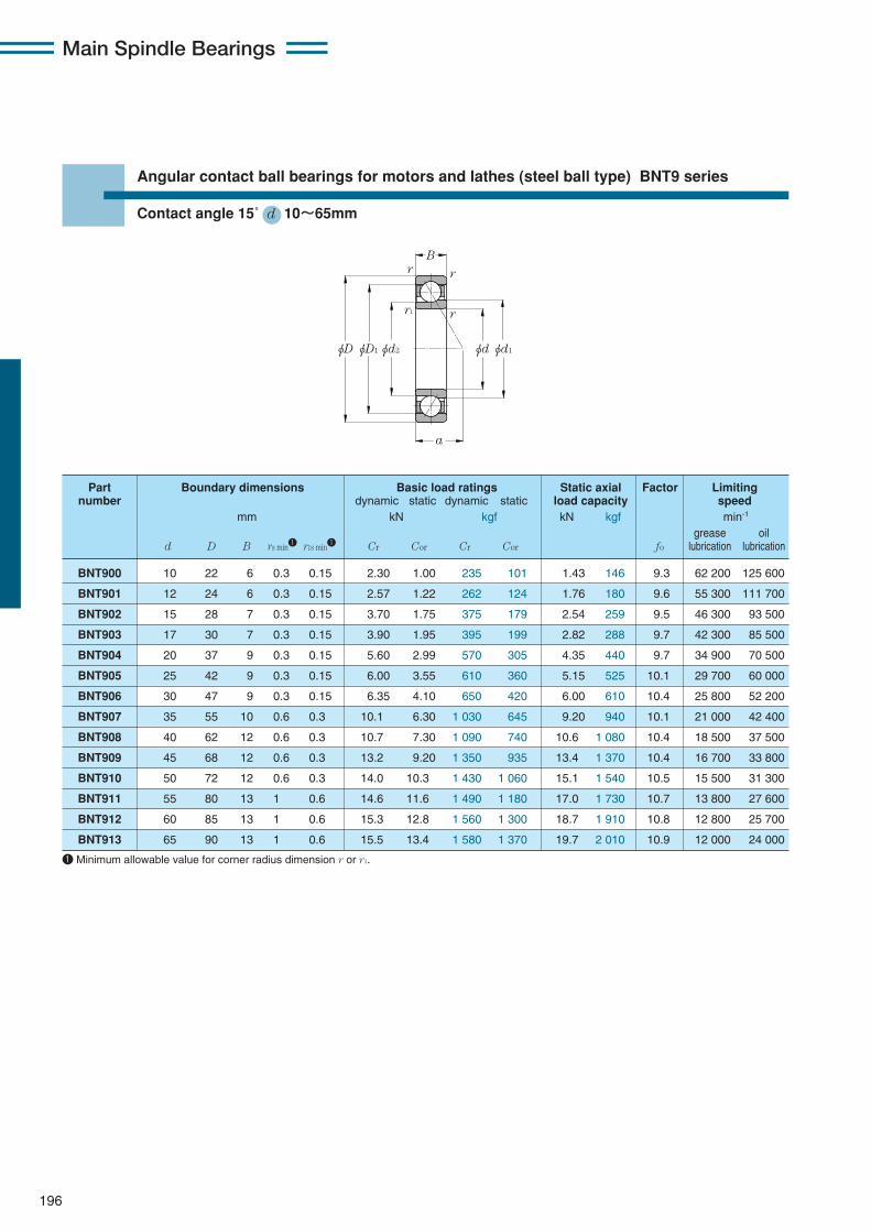
196
Angular contact ball bearings for motors and lathes (steel ball type) BNT9 series
Contact angle 15˚ d 10〜65mm
1 Minimum allowable value for corner radius dimension r or r1.
Main Spindle Bearings
φD
a
B
φD1φd2 φdφd1
r r
rr1
BNT900 10 22 6 0.3 0.15 2.30 1.00 235 101 1.43 146 9.3 62 200 125 600
BNT901 12 24 6 0.3 0.15 2.57 1.22 262 124 1.76 180 9.6 55 300 111 700
BNT902 15 28 7 0.3 0.15 3.70 1.75 375 179 2.54 259 9.5 46 300 93 500
BNT903 17 30 7 0.3 0.15 3.90 1.95 395 199 2.82 288 9.7 42 300 85 500
BNT904 20 37 9 0.3 0.15 5.60 2.99 570 305 4.35 440 9.7 34 900 70 500
BNT905 25 42 9 0.3 0.15 6.00 3.55 610 360 5.15 525 10.1 29 700 60 000
BNT906 30 47 9 0.3 0.15 6.35 4.10 650 420 6.00 610 10.4 25 800 52 200
BNT907 35 55 10 0.6 0.3 10.1 6.30 1 030 645 9.20 940 10.1 21 000 42 400
BNT908 40 62 12 0.6 0.3 10.7 7.30 1 090 740 10.6 1 080 10.4 18 500 37 500
BNT909 45 68 12 0.6 0.3 13.2 9.20 1 350 935 13.4 1 370 10.4 16 700 33 800
BNT910 50 72 12 0.6 0.3 14.0 10.3 1 430 1 060 15.1 1 540 10.5 15 500 31 300
BNT911 55 80 13 1 0.6 14.6 11.6 1 490 1 180 17.0 1 730 10.7 13 800 27 600
BNT912 60 85 13 1 0.6 15.3 12.8 1 560 1 300 18.7 1 910 10.8 12 800 25 700
BNT913 65 90 13 1 0.6 15.5 13.4 1 580 1 370 19.7 2 010 10.9 12 000 24 000
Part Boundary dimensions Basic load ratings Static axial Factor Limitingnumber dynamic static dynamic static load capacity speed
mm kN kgf kN kgf min-1
grease oild D B rs min1 r1s min1 Cr Cor Cr Cor fo lubrication lubrication
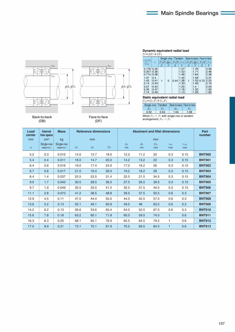
197
Main Spindle Bearings
0.178 0.357 0.714 1.07 1.43 2.14 3.57 5.35 7.14
eX Y
Dynamic equivalent radial loadPr=XFr+YFa
Static equivalent radial loadPor=Xo Fr+Yo Fa
Fa/Fr≦e Fa/Fr>e Fa/Fr≦e Fa/Fr>eX Y X Y X Y
0.35 0.36 0.38 0.4 0.41 0.43 0.44 0.47 0.49
1 0 0.44
1.57 1.53 1.46 1.42 1.38 1.33 1.25 1.18 1.13
1
1.76 1.71 1.64 1.59 1.55 1.49 1.4 1.32 1.26
0.72
2.56 2.48 2.38 2.31 2.25 2.16 2.03 1.92 1.83
When Por < Fr with single-row or tandem arrangement, Por = Fr.
Xo0.52
Yo Xo Yo0.54 1.04 1.08
Cor
i・fo・Fa
Single row / Tandem Back-to-back / Face-to-face
Single row / Tandem Back-to-back / Face-to-face
Back-to-back (DB)
Face-to-face (DF)
φDaφdbφDaφda
ras
ras
ras
r1as
5.2 0.3 0.010 14.0 12.7 18.0 12.2 11.2 20 0.3 0.15 BNT900
5.4 0.4 0.011 16.0 14.7 20.0 14.2 13.2 22 0.3 0.15 BNT901
6.4 0.6 0.016 19.0 17.4 24.0 17.2 16.2 26 0.3 0.15 BNT902
6.7 0.8 0.017 21.0 19.4 26.0 19.2 18.2 28 0.3 0.15 BNT903
8.4 1.4 0.037 25.5 23.5 31.4 22.5 21.5 34.5 0.3 0.15 BNT904
9.0 1.7 0.043 30.5 28.5 36.5 27.5 26.5 39.5 0.3 0.15 BNT905
9.7 1.9 0.049 35.5 33.5 41.5 32.5 31.5 44.5 0.3 0.15 BNT906
11.1 2.8 0.073 41.2 38.5 48.8 39.5 37.5 50.5 0.6 0.3 BNT907
12.9 4.5 0.11 47.0 44.4 55.0 44.5 42.5 57.5 0.6 0.3 BNT908
13.6 5.2 0.13 52.1 49.1 60.9 49.5 48 63.5 0.6 0.3 BNT909
14.2 6.2 0.13 56.6 53.6 65.4 54.5 52.5 67.5 0.6 0.3 BNT910
15.6 7.8 0.18 63.2 60.1 71.8 60.5 59.5 74.5 1 0.6 BNT911
16.3 8.3 0.20 68.1 65.1 76.9 65.5 64.5 79.5 1 0.6 BNT912
17.0 8.9 0.21 73.1 70.1 81.9 70.5 69.5 84.5 1 0.6 BNT913
Load Internal Mass Reference dimensions Abutment and fillet dimensions Partcenter free space number
mm cm3 kg mm mm
Single-row Single-row da db Da ras r1asa (approx.) (approx.) d1 d2 D1 min min max max max
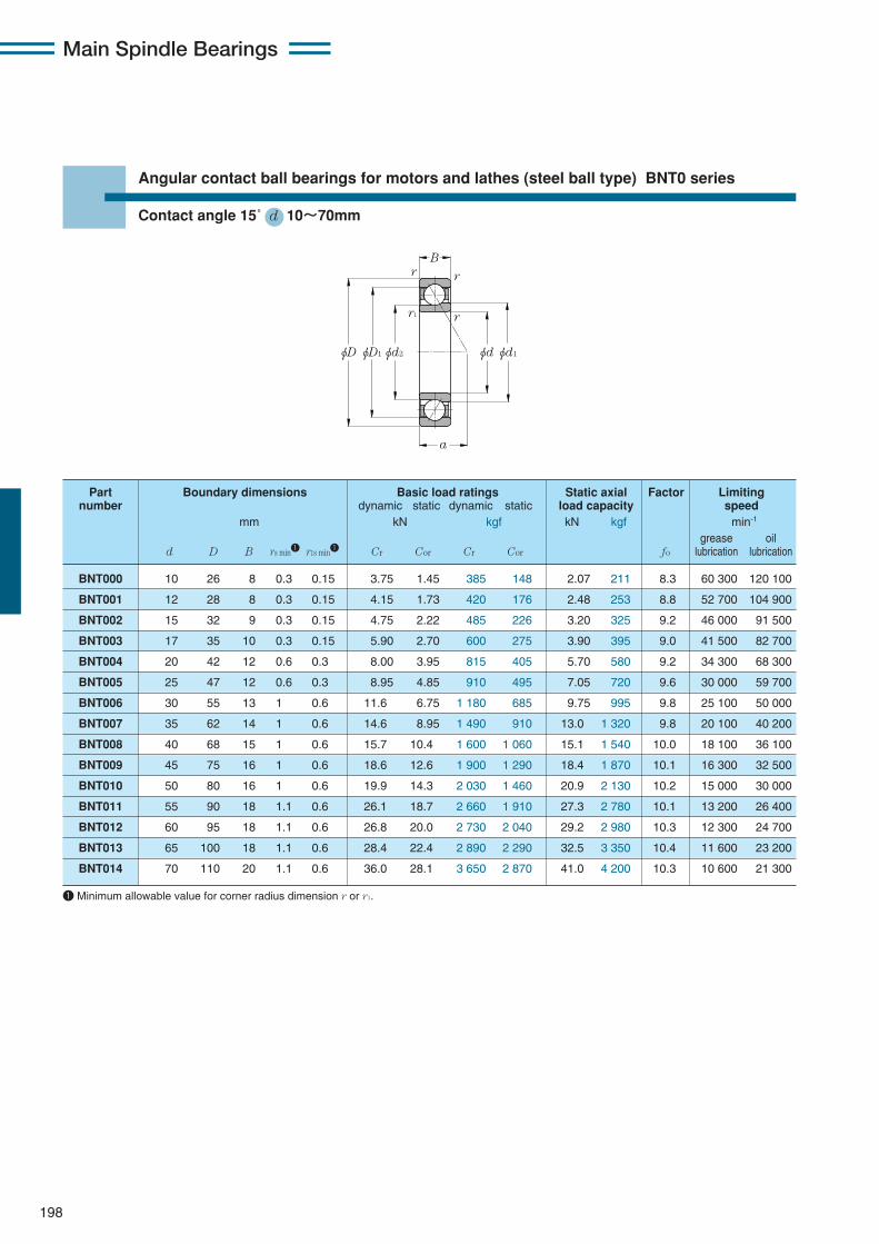
198
Angular contact ball bearings for motors and lathes (steel ball type) BNT0 series
Contact angle 15˚ d 10〜70mm
1 Minimum allowable value for corner radius dimension r or r1.
Main Spindle Bearings
φD
a
B
φD1φd2 φdφd1
r r
rr1
BNT000 10 26 8 0.3 0.15 3.75 1.45 385 148 2.07 211 8.3 60 300 120 100
BNT001 12 28 8 0.3 0.15 4.15 1.73 420 176 2.48 253 8.8 52 700 104 900
BNT002 15 32 9 0.3 0.15 4.75 2.22 485 226 3.20 325 9.2 46 000 91 500
BNT003 17 35 10 0.3 0.15 5.90 2.70 600 275 3.90 395 9.0 41 500 82 700
BNT004 20 42 12 0.6 0.3 8.00 3.95 815 405 5.70 580 9.2 34 300 68 300
BNT005 25 47 12 0.6 0.3 8.95 4.85 910 495 7.05 720 9.6 30 000 59 700
BNT006 30 55 13 1 0.6 11.6 6.75 1 180 685 9.75 995 9.8 25 100 50 000
BNT007 35 62 14 1 0.6 14.6 8.95 1 490 910 13.0 1 320 9.8 20 100 40 200
BNT008 40 68 15 1 0.6 15.7 10.4 1 600 1 060 15.1 1 540 10.0 18 100 36 100
BNT009 45 75 16 1 0.6 18.6 12.6 1 900 1 290 18.4 1 870 10.1 16 300 32 500
BNT010 50 80 16 1 0.6 19.9 14.3 2 030 1 460 20.9 2 130 10.2 15 000 30 000
BNT011 55 90 18 1.1 0.6 26.1 18.7 2 660 1 910 27.3 2 780 10.1 13 200 26 400
BNT012 60 95 18 1.1 0.6 26.8 20.0 2 730 2 040 29.2 2 980 10.3 12 300 24 700
BNT013 65 100 18 1.1 0.6 28.4 22.4 2 890 2 290 32.5 3 350 10.4 11 600 23 200
BNT014 70 110 20 1.1 0.6 36.0 28.1 3 650 2 870 41.0 4 200 10.3 10 600 21 300
Part Boundary dimensions Basic load ratings Static axial Factor Limitingnumber dynamic static dynamic static load capacity speed
mm kN kgf kN kgf min-1
grease oild D B rs min1 r1s min1 Cr Cor Cr Cor fo lubrication lubrication
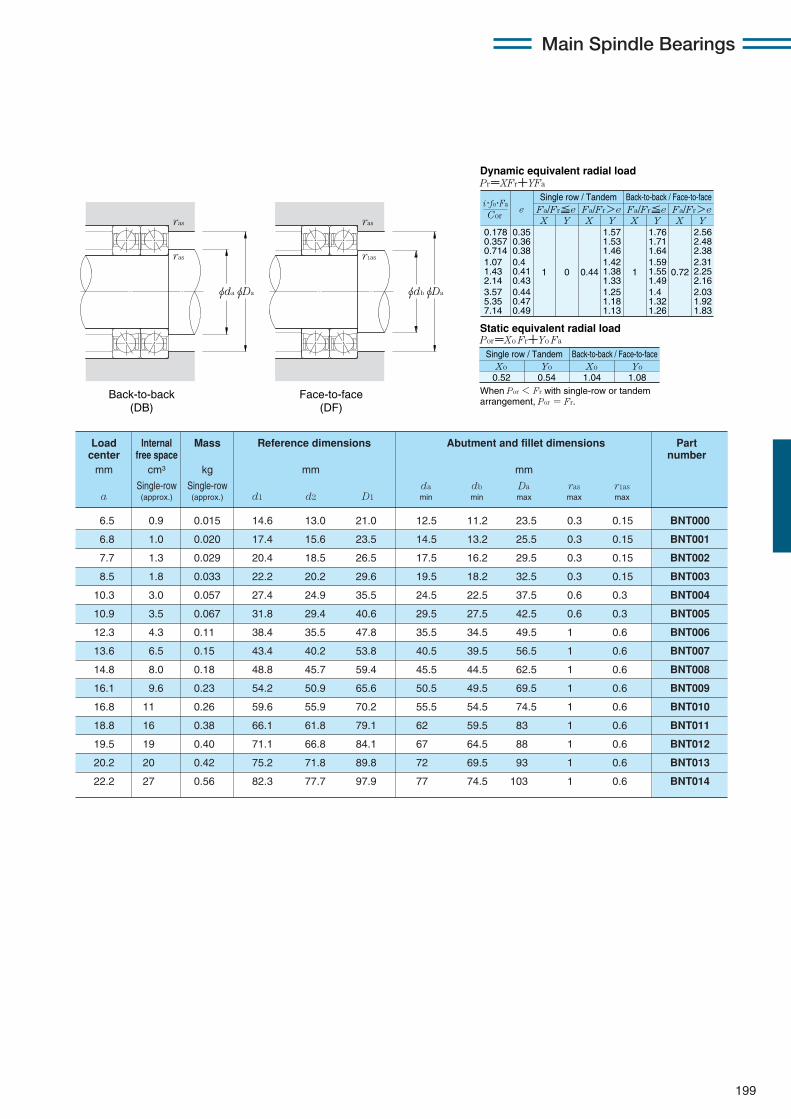
199
Main Spindle Bearings
0.178 0.357 0.714 1.07 1.43 2.14 3.57 5.35 7.14
eX Y
Dynamic equivalent radial loadPr=XFr+YFa
Static equivalent radial loadPor=Xo Fr+Yo Fa
Fa/Fr≦e Fa/Fr>e Fa/Fr≦e Fa/Fr>eX Y X Y X Y
0.35 0.36 0.38 0.4 0.41 0.43 0.44 0.47 0.49
1 0 0.44
1.57 1.53 1.46 1.42 1.38 1.33 1.25 1.18 1.13
1
1.76 1.71 1.64 1.59 1.55 1.49 1.4 1.32 1.26
0.72
2.56 2.48 2.38 2.31 2.25 2.16 2.03 1.92 1.83
When Por < Fr with single-row or tandem arrangement, Por = Fr.
Xo0.52
Yo Xo Yo0.54 1.04 1.08
Cor
i・fo・Fa
Single row / Tandem Back-to-back / Face-to-face
Single row / Tandem Back-to-back / Face-to-face
6.5 0.9 0.015 14.6 13.0 21.0 12.5 11.2 23.5 0.3 0.15 BNT000
6.8 1.0 0.020 17.4 15.6 23.5 14.5 13.2 25.5 0.3 0.15 BNT001
7.7 1.3 0.029 20.4 18.5 26.5 17.5 16.2 29.5 0.3 0.15 BNT002
8.5 1.8 0.033 22.2 20.2 29.6 19.5 18.2 32.5 0.3 0.15 BNT003
10.3 3.0 0.057 27.4 24.9 35.5 24.5 22.5 37.5 0.6 0.3 BNT004
10.9 3.5 0.067 31.8 29.4 40.6 29.5 27.5 42.5 0.6 0.3 BNT005
12.3 4.3 0.11 38.4 35.5 47.8 35.5 34.5 49.5 1 0.6 BNT006
13.6 6.5 0.15 43.4 40.2 53.8 40.5 39.5 56.5 1 0.6 BNT007
14.8 8.0 0.18 48.8 45.7 59.4 45.5 44.5 62.5 1 0.6 BNT008
16.1 9.6 0.23 54.2 50.9 65.6 50.5 49.5 69.5 1 0.6 BNT009
16.8 11 0.26 59.6 55.9 70.2 55.5 54.5 74.5 1 0.6 BNT010
18.8 16 0.38 66.1 61.8 79.1 62 59.5 83 1 0.6 BNT011
19.5 19 0.40 71.1 66.8 84.1 67 64.5 88 1 0.6 BNT012
20.2 20 0.42 75.2 71.8 89.8 72 69.5 93 1 0.6 BNT013
22.2 27 0.56 82.3 77.7 97.9 77 74.5 103 1 0.6 BNT014
Load Internal Mass Reference dimensions Abutment and fillet dimensions Part center free space number
mm cm3 kg mm mm
Single-row Single-row da db Da ras r1asa (approx.) (approx.) d1 d2 D1 min min max max max
Back-to-back (DB)
Face-to-face (DF)
φDaφdbφDaφda
ras
ras
ras
r1as
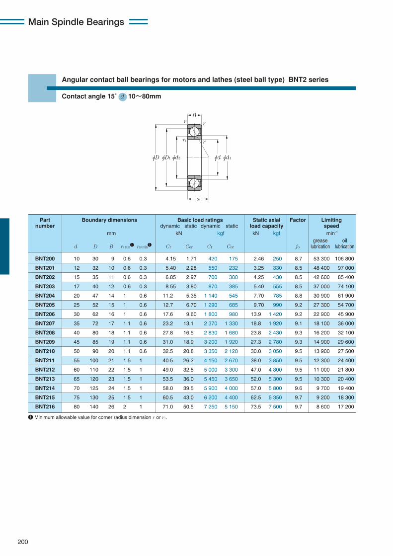
200
Angular contact ball bearings for motors and lathes (steel ball type) BNT2 series
Contact angle 15˚ d 10〜80mm
1 Minimum allowable value for corner radius dimension r or r1.
Main Spindle Bearings
φD
a
B
φD1φd2 φdφd1
r r
rr1
BNT200 10 30 9 0.6 0.3 4.15 1.71 420 175 2.46 250 8.7 53 300 106 800
BNT201 12 32 10 0.6 0.3 5.40 2.28 550 232 3.25 330 8.5 48 400 97 000
BNT202 15 35 11 0.6 0.3 6.85 2.97 700 300 4.25 430 8.5 42 600 85 400
BNT203 17 40 12 0.6 0.3 8.55 3.80 870 385 5.40 555 8.5 37 000 74 100
BNT204 20 47 14 1 0.6 11.2 5.35 1 140 545 7.70 785 8.8 30 900 61 900
BNT205 25 52 15 1 0.6 12.7 6.70 1 290 685 9.70 990 9.2 27 300 54 700
BNT206 30 62 16 1 0.6 17.6 9.60 1 800 980 13.9 1 420 9.2 22 900 45 900
BNT207 35 72 17 1.1 0.6 23.2 13.1 2 370 1 330 18.8 1 920 9.1 18 100 36 000
BNT208 40 80 18 1.1 0.6 27.8 16.5 2 830 1 680 23.8 2 430 9.3 16 200 32 100
BNT209 45 85 19 1.1 0.6 31.0 18.9 3 200 1 920 27.3 2 780 9.3 14 900 29 600
BNT210 50 90 20 1.1 0.6 32.5 20.8 3 350 2 120 30.0 3 050 9.5 13 900 27 500
BNT211 55 100 21 1.5 1 40.5 26.2 4 150 2 670 38.0 3 850 9.5 12 300 24 400
BNT212 60 110 22 1.5 1 49.0 32.5 5 000 3 300 47.0 4 800 9.5 11 000 21 800
BNT213 65 120 23 1.5 1 53.5 36.0 5 450 3 650 52.0 5 300 9.5 10 300 20 400
BNT214 70 125 24 1.5 1 58.0 39.5 5 900 4 000 57.0 5 800 9.6 9 700 19 400
BNT215 75 130 25 1.5 1 60.5 43.0 6 200 4 400 62.5 6 350 9.7 9 200 18 300
BNT216 80 140 26 2 1 71.0 50.5 7 250 5 150 73.5 7 500 9.7 8 600 17 200
Part Boundary dimensions Basic load ratings Static axial Factor Limitingnumber dynamic static dynamic static load capacity speed
mm kN kgf kN kgf min-1
grease oild D B rs min1 r1s min1 Cr Cor Cr Cor fo lubrication lubrication
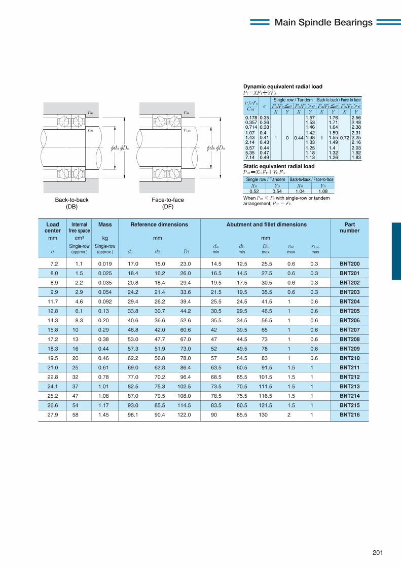
201
Main Spindle Bearings
0.178 0.357 0.714 1.07 1.43 2.14 3.57 5.35 7.14
eX Y
Dynamic equivalent radial loadPr=XFr+YFa
Static equivalent radial loadPor=Xo Fr+Yo Fa
Fa/Fr≦e Fa/Fr>e Fa/Fr≦e Fa/Fr>eX Y X Y X Y
0.35 0.36 0.38 0.4 0.41 0.43 0.44 0.47 0.49
1 0 0.44
1.57 1.53 1.46 1.42 1.38 1.33 1.25 1.18 1.13
1
1.76 1.71 1.64 1.59 1.55 1.49 1.4 1.32 1.26
0.72
2.56 2.48 2.38 2.31 2.25 2.16 2.03 1.92 1.83
When Por < Fr with single-row or tandem arrangement, Por = Fr.
Xo0.52
Yo Xo Yo0.54 1.04 1.08
Cor
i・fo・Fa
Single row / Tandem Back-to-back / Face-to-face
Single row / Tandem Back-to-back / Face-to-face
7.2 1.1 0.019 17.0 15.0 23.0 14.5 12.5 25.5 0.6 0.3 BNT200
8.0 1.5 0.025 18.4 16.2 26.0 16.5 14.5 27.5 0.6 0.3 BNT201
8.9 2.2 0.035 20.8 18.4 29.4 19.5 17.5 30.5 0.6 0.3 BNT202
9.9 2.9 0.054 24.2 21.4 33.6 21.5 19.5 35.5 0.6 0.3 BNT203
11.7 4.6 0.092 29.4 26.2 39.4 25.5 24.5 41.5 1 0.6 BNT204
12.8 6.1 0.13 33.8 30.7 44.2 30.5 29.5 46.5 1 0.6 BNT205
14.3 8.3 0.20 40.6 36.6 52.6 35.5 34.5 56.5 1 0.6 BNT206
15.8 10 0.29 46.8 42.0 60.6 42 39.5 65 1 0.6 BNT207
17.2 13 0.38 53.0 47.7 67.0 47 44.5 73 1 0.6 BNT208
18.3 16 0.44 57.3 51.9 73.0 52 49.5 78 1 0.6 BNT209
19.5 20 0.46 62.2 56.8 78.0 57 54.5 83 1 0.6 BNT210
21.0 25 0.61 69.0 62.8 86.4 63.5 60.5 91.5 1.5 1 BNT211
22.8 32 0.78 77.0 70.2 96.4 68.5 65.5 101.5 1.5 1 BNT212
24.1 37 1.01 82.5 75.3 102.5 73.5 70.5 111.5 1.5 1 BNT213
25.2 47 1.08 87.0 79.5 108.0 78.5 75.5 116.5 1.5 1 BNT214
26.6 54 1.17 93.0 85.5 114.5 83.5 80.5 121.5 1.5 1 BNT215
27.9 58 1.45 98.1 90.4 122.0 90 85.5 130 2 1 BNT216
Load Internal Mass Reference dimensions Abutment and fillet dimensions Partcenter free space number
mm cm3 kg mm mm
Single-row Single-row da db Da ras r1asa (approx.) (approx.) d1 d2 D1 min min max max max
Back-to-back (DB)
Face-to-face (DF)
φDaφdbφDaφda
ras
ras
ras
r1as
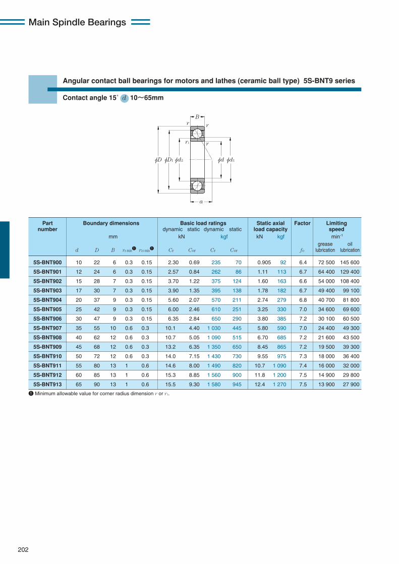
202
Angular contact ball bearings for motors and lathes (ceramic ball type) 5S-BNT9 series
Contact angle 15˚ d 10〜65mm
1 Minimum allowable value for corner radius dimension r or r1.
Main Spindle Bearings
φD
a
B
φD1φd2 φdφd1
r r
rr1
5S-BNT900 10 22 6 0.3 0.15 2.30 0.69 235 70 0.905 92 6.4 72 500 145 600
5S-BNT901 12 24 6 0.3 0.15 2.57 0.84 262 86 1.11 113 6.7 64 400 129 400
5S-BNT902 15 28 7 0.3 0.15 3.70 1.22 375 124 1.60 163 6.6 54 000 108 400
5S-BNT903 17 30 7 0.3 0.15 3.90 1.35 395 138 1.78 182 6.7 49 400 99 100
5S-BNT904 20 37 9 0.3 0.15 5.60 2.07 570 211 2.74 279 6.8 40 700 81 800
5S-BNT905 25 42 9 0.3 0.15 6.00 2.46 610 251 3.25 330 7.0 34 600 69 600
5S-BNT906 30 47 9 0.3 0.15 6.35 2.84 650 290 3.80 385 7.2 30 100 60 500
5S-BNT907 35 55 10 0.6 0.3 10.1 4.40 1 030 445 5.80 590 7.0 24 400 49 300
5S-BNT908 40 62 12 0.6 0.3 10.7 5.05 1 090 515 6.70 685 7.2 21 600 43 500
5S-BNT909 45 68 12 0.6 0.3 13.2 6.35 1 350 650 8.45 865 7.2 19 500 39 300
5S-BNT910 50 72 12 0.6 0.3 14.0 7.15 1 430 730 9.55 975 7.3 18 000 36 400
5S-BNT911 55 80 13 1 0.6 14.6 8.00 1 490 820 10.7 1 090 7.4 16 000 32 000
5S-BNT912 60 85 13 1 0.6 15.3 8.85 1 560 900 11.8 1 200 7.5 14 900 29 800
5S-BNT913 65 90 13 1 0.6 15.5 9.30 1 580 945 12.4 1 270 7.5 13 900 27 900
Part Boundary dimensions Basic load ratings Static axial Factor Limitingnumber dynamic static dynamic static load capacity speed
mm kN kgf kN kgf min-1
grease oild D B rs min1 r1s min1 Cr Cor Cr Cor fo lubrication lubrication
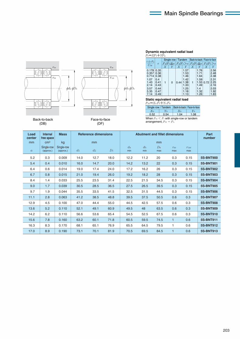
203
Main Spindle Bearings
0.178 0.357 0.714 1.07 1.43 2.14 3.57 5.35 7.14
eX Y
Dynamic equivalent radial loadPr=XFr+YFa
Static equivalent radial loadPor=Xo Fr+Yo Fa
Fa/Fr≦e Fa/Fr>e Fa/Fr≦e Fa/Fr>eX Y X Y X Y
0.35 0.36 0.38 0.4 0.41 0.43 0.44 0.47 0.49
1 0 0.44
1.57 1.53 1.46 1.42 1.38 1.33 1.25 1.18 1.13
1
1.76 1.71 1.64 1.59 1.55 1.49 1.4 1.32 1.26
0.72
2.56 2.48 2.38 2.31 2.25 2.16 2.03 1.92 1.83
When Por < Fr with single-row or tandem arrangement, Por = Fr.
Xo0.52
Yo Xo Yo0.54 1.04 1.08
Cor
i・fo・Fa
Single row / Tandem Back-to-back / Face-to-face
Single row / Tandem Back-to-back / Face-to-face
5.2 0.3 0.009 14.0 12.7 18.0 12.2 11.2 20 0.3 0.15 5S-BNT900
5.4 0.4 0.010 16.0 14.7 20.0 14.2 13.2 22 0.3 0.15 5S-BNT901
6.4 0.6 0.014 19.0 17.4 24.0 17.2 16.2 26 0.3 0.15 5S-BNT902
6.7 0.8 0.015 21.0 19.4 26.0 19.2 18.2 28 0.3 0.15 5S-BNT903
8.4 1.4 0.033 25.5 23.5 31.4 22.5 21.5 34.5 0.3 0.15 5S-BNT904
9.0 1.7 0.039 30.5 28.5 36.5 27.5 26.5 39.5 0.3 0.15 5S-BNT905
9.7 1.9 0.044 35.5 33.5 41.5 32.5 31.5 44.5 0.3 0.15 5S-BNT906
11.1 2.8 0.063 41.2 38.5 48.8 39.5 37.5 50.5 0.6 0.3 5S-BNT907
12.9 4.5 0.100 47.0 44.4 55.0 44.5 42.5 57.5 0.6 0.3 5S-BNT908
13.6 5.2 0.110 52.1 49.1 60.9 49.5 48 63.5 0.6 0.3 5S-BNT909
14.2 6.2 0.110 56.6 53.6 65.4 54.5 52.5 67.5 0.6 0.3 5S-BNT910
15.6 7.8 0.160 63.2 60.1 71.8 60.5 59.5 74.5 1 0.6 5S-BNT911
16.3 8.3 0.170 68.1 65.1 76.9 65.5 64.5 79.5 1 0.6 5S-BNT912
17.0 8.9 0.190 73.1 70.1 81.9 70.5 69.5 84.5 1 0.6 5S-BNT913
Load Internal Mass Reference dimensions Abutment and fillet dimensions Partcenter free space number
mm cm3 kg mm mm
Single-row Single-row da db Da ras r1asa (approx.) (approx.) d1 d2 D1 min min max max max
Back-to-back (DB)
Face-to-face (DF)
φDaφdbφDaφda
ras
ras
ras
r1as

204
Angular contact ball bearings for motors and lathes (ceramic ball type) 5S-BNT0 series
Contact angle 15˚ d 10〜70mm
1 Minimum allowable value for corner radius dimension r or r1.
Main Spindle Bearings
φD
a
B
φD1φd2 φdφd1
r r
rr1
5S-BNT000 10 26 8 0.3 0.15 3.75 1.01 385 103 1.31 133 5.7 70 100 140 200
5S-BNT001 12 28 8 0.3 0.15 4.15 1.20 420 122 1.57 160 6.1 61 200 122 400
5S-BNT002 15 32 9 0.3 0.15 4.75 1.54 485 157 2.02 206 6.4 53 400 106 800
5S-BNT003 17 35 10 0.3 0.15 5.90 1.87 600 191 2.45 250 6.3 48 300 96 500
5S-BNT004 20 42 12 0.6 0.3 8.00 2.74 815 279 3.60 365 6.4 39 800 79 700
5S-BNT005 25 47 12 0.6 0.3 8.95 3.35 910 345 4.45 455 6.7 34 900 69 700
5S-BNT006 30 55 13 1 0.6 11.6 4.65 1 180 475 6.15 630 6.8 29 200 58 400
5S-BNT007 35 62 14 1 0.6 14.6 6.20 1 490 630 8.20 835 6.8 23 500 46 900
5S-BNT008 40 68 15 1 0.6 15.7 7.20 1 600 735 9.55 975 7.0 21 100 42 100
5S-BNT009 45 75 16 1 0.6 18.6 8.75 1 900 890 11.6 1 180 7.0 19 000 37 900
5S-BNT010 50 80 16 1 0.6 19.9 9.90 2 030 1 010 13.2 1 340 7.1 17 500 35 000
5S-BNT011 55 90 18 1.1 0.6 26.1 13.0 2 660 1 320 17.2 1 760 7.0 15 500 31 000
5S-BNT012 60 95 18 1.1 0.6 26.8 13.9 2 730 1 420 18.4 1 880 7.1 14 500 29 000
5S-BNT013 65 100 18 1.1 0.6 28.4 15.5 2 890 1 580 20.7 2 110 7.2 13 600 27 300
5S-BNT014 70 110 20 1.1 0.6 36.0 19.5 3 650 1 990 25.9 2 640 7.1 12 500 25 000
Part Boundary dimensions Basic load ratings Static axial Factor Limitingnumber dynamic static dynamic static load capacity speed
mm kN kgf kN kgf min-1
grease oild D B rs min1 r1s min1 Cr Cor Cr Cor fo lubrication lubrication

205
Main Spindle Bearings
0.178 0.357 0.714 1.07 1.43 2.14 3.57 5.35 7.14
eX Y
Dynamic equivalent radial loadPr=XFr+YFa
Static equivalent radial loadPor=Xo Fr+Yo Fa
Fa/Fr≦e Fa/Fr>e Fa/Fr≦e Fa/Fr>eX Y X Y X Y
0.35 0.36 0.38 0.4 0.41 0.43 0.44 0.47 0.49
1 0 0.44
1.57 1.53 1.46 1.42 1.38 1.33 1.25 1.18 1.13
1
1.76 1.71 1.64 1.59 1.55 1.49 1.4 1.32 1.26
0.72
2.56 2.48 2.38 2.31 2.25 2.16 2.03 1.92 1.83
When Por < Fr with single-row or tandem arrangement, Por = Fr.
Xo0.52
Yo Xo Yo0.54 1.04 1.08
Cor
i・fo・Fa
Single row / Tandem Back-to-back / Face-to-face
Single row / Tandem Back-to-back / Face-to-face
6.5 0.9 0.013 14.6 13.0 21.0 12.5 11.2 23.5 0.3 0.15 5S-BNT000
6.8 1.0 0.018 17.4 15.6 23.5 14.5 13.2 25.5 0.3 0.15 5S-BNT001
7.7 1.3 0.026 20.4 18.5 26.5 17.5 16.2 29.5 0.3 0.15 5S-BNT002
8.5 1.8 0.029 22.2 20.2 29.6 19.5 18.2 32.5 0.3 0.15 5S-BNT003
10.3 3.0 0.050 27.4 24.9 35.5 24.5 22.5 37.5 0.6 0.3 5S-BNT004
10.9 3.5 0.060 31.8 29.4 40.6 29.5 27.5 42.5 0.6 0.3 5S-BNT005
12.3 4.3 0.10 38.4 35.5 47.8 35.5 34.5 49.5 1 0.6 5S-BNT006
13.6 6.5 0.13 43.4 40.2 53.8 40.5 39.5 56.5 1 0.6 5S-BNT007
14.8 8.0 0.16 48.8 45.7 59.4 45.5 44.5 62.5 1 0.6 5S-BNT008
16.1 9.6 0.21 54.2 50.9 65.6 50.5 49.5 69.5 1 0.6 5S-BNT009
16.8 11 0.24 59.6 55.9 70.2 55.5 54.5 74.5 1 0.6 5S-BNT010
18.8 16 0.35 66.1 61.8 79.1 62 59.5 83 1 0.6 5S-BNT011
19.5 19 0.36 71.1 66.8 84.1 67 64.5 88 1 0.6 5S-BNT012
20.2 20 0.37 75.2 71.8 89.8 72 69.5 93 1 0.6 5S-BNT013
22.2 27 0.50 82.3 77.7 97.9 77 74.5 103 1 0.6 5S-BNT014
Load Internal Mass Reference dimensions Abutment and fillet dimensions Partcenter free space number
mm cm3 kg mm mm
Single-row Single-row da db Da ras r1asa (approx.) (approx.) d1 d2 D1 min min max max max
Back-to-back (DB)
Face-to-face (DF)
φDaφdbφDaφda
ras
ras
ras
r1as
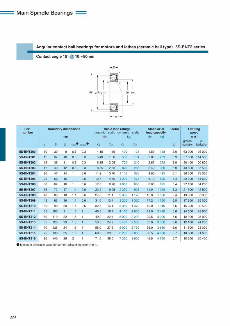
206
Angular contact ball bearings for motors and lathes (ceramic ball type) 5S-BNT2 series
Contact angle 15˚ d 10〜80mm
1 Minimum allowable value for corner radius dimension r or r1.
Main Spindle Bearings
φD
a
B
φD1φd2 φdφd1
r r
rr1
5S-BNT200 10 30 9 0.6 0.3 4.15 1.19 420 121 1.55 158 6.0 63 000 126 000
5S-BNT201 12 32 10 0.6 0.3 5.40 1.58 550 161 2.05 209 5.9 57 300 114 500
5S-BNT202 15 35 11 0.6 0.3 6.85 2.05 700 210 2.67 272 5.9 50 400 100 800
5S-BNT203 17 40 12 0.6 0.3 8.55 2.63 870 268 3.40 350 5.9 43 800 87 500
5S-BNT204 20 47 14 1 0.6 11.2 3.70 1 140 380 4.85 495 6.1 36 500 73 000
5S-BNT205 25 52 15 1 0.6 12.7 4.65 1 290 475 6.10 625 6.4 32 300 64 600
5S-BNT206 30 62 16 1 0.6 17.6 6.70 1 800 680 8.80 895 6.4 27 100 54 200
5S-BNT207 35 72 17 1.1 0.6 23.2 9.05 2 370 925 11.9 1 210 6.3 21 300 42 500
5S-BNT208 40 80 18 1.1 0.6 27.8 11.4 2 830 1 170 15.0 1 530 6.4 19 000 37 900
5S-BNT209 45 85 19 1.1 0.6 31.0 13.1 3 200 1 330 17.2 1 750 6.5 17 500 35 000
5S-BNT210 50 90 20 1.1 0.6 32.5 14.4 3 350 1 470 19.0 1 940 6.6 16 300 32 500
5S-BNT211 55 100 21 1.5 1 40.5 18.1 4 150 1 850 23.9 2 440 6.6 14 500 28 900
5S-BNT212 60 110 22 1.5 1 49.0 22.4 5 000 2 290 29.5 3 000 6.6 12 900 25 900
5S-BNT213 65 120 23 1.5 1 53.5 24.9 5 450 2 530 33.0 3 350 6.6 12 100 24 200
5S-BNT214 70 125 24 1.5 1 58.0 27.3 5 900 2 790 36.0 3 650 6.6 11 500 23 000
5S-BNT215 75 130 25 1.5 1 60.5 29.8 6 200 3 050 39.5 4 000 6.7 10 800 21 600
5S-BNT216 80 140 26 2 1 71.0 35.0 7 250 3 600 46.5 4 750 6.7 10 200 20 400
Part Boundary dimensions Basic load ratings Static axial Factor Limitingnumber dynamic static dynamic static load capacity speed
mm kN kgf kN kgf min-1
grease oild D B rs min1 r1s min1 Cr Cor Cr Cor fo lubrication lubrication

207
Main Spindle Bearings
0.178 0.357 0.714 1.07 1.43 2.14 3.57 5.35 7.14
eX Y
Dynamic equivalent radial loadPr=XFr+YFa
Static equivalent radial loadPor=Xo Fr+Yo Fa
Fa/Fr≦e Fa/Fr>e Fa/Fr≦e Fa/Fr>eX Y X Y X Y
0.35 0.36 0.38 0.4 0.41 0.43 0.44 0.47 0.49
1 0 0.44
1.57 1.53 1.46 1.42 1.38 1.33 1.25 1.18 1.13
1
1.76 1.71 1.64 1.59 1.55 1.49 1.4 1.32 1.26
0.72
2.56 2.48 2.38 2.31 2.25 2.16 2.03 1.92 1.83
When Por < Fr with single-row or tandem arrangement, Por = Fr.
Xo0.52
Yo Xo Yo0.54 1.04 1.08
Cor
i・fo・Fa
Single row / Tandem Back-to-back / Face-to-face
Single row / Tandem Back-to-back / Face-to-face
7.2 1.1 0.017 17.0 15.0 23.0 14.5 12.5 25.5 0.6 0.3 5S-BNT200
8.0 1.5 0.021 18.4 16.2 26.0 16.5 14.5 27.5 0.6 0.3 5S-BNT201
8.9 2.2 0.030 20.8 18.4 29.4 19.5 17.5 30.5 0.6 0.3 5S-BNT202
9.9 2.9 0.046 24.2 21.4 33.6 21.5 19.5 35.5 0.6 0.3 5S-BNT203
11.7 4.6 0.080 29.4 26.2 39.4 25.5 24.5 41.5 1 0.6 5S-BNT204
12.8 6.1 0.11 33.8 30.7 44.2 30.5 29.5 46.5 1 0.6 5S-BNT205
14.3 8.3 0.18 40.6 36.6 52.6 35.5 34.5 56.5 1 0.6 5S-BNT206
15.8 10 0.25 46.8 42.0 60.6 42 39.5 65 1 0.6 5S-BNT207
17.2 13 0.33 53.0 47.7 67.0 47 44.5 73 1 0.6 5S-BNT208
18.3 16 0.37 57.3 51.9 73.0 52 49.5 78 1 0.6 5S-BNT209
19.5 20 0.39 62.2 56.8 78.0 57 54.5 83 1 0.6 5S-BNT210
21.0 25 0.52 69.0 62.8 86.4 63.5 60.5 91.5 1.5 1 5S-BNT211
22.8 32 0.65 77.0 70.2 96.4 68.5 65.5 101.5 1.5 1 5S-BNT212
24.1 37 0.86 82.5 75.3 102.5 73.5 70.5 111.5 1.5 1 5S-BNT213
25.2 47 0.91 87.0 79.5 108.0 78.5 75.5 116.5 1.5 1 5S-BNT214
26.6 54 0.98 93.0 85.5 114.5 83.5 80.5 121.5 1.5 1 5S-BNT215
27.9 58 1.21 98.1 90.4 122.0 90 85.5 130 2 1 5S-BNT216
Load Internal Mass Reference dimensions Abutment and fillet dimensions Partcenter free space number
mm cm3 kg mm mm
Single-row Single-row da db Da ras r1asa (approx.) (approx.) d1 d2 D1 min min max max max
Back-to-back (DB)
Face-to-face (DF)
φDaφdbφDaφda
ras
ras
ras
r1as

NTN Main Spindle Bearings
208

NTN Main Spindle Bearings
209
Main Spindle Bearings
10. Cylindrical Roller Bearings CONTENTS
10. Cylindrical roller bearings ……………………………………………………210〜237q Double-row cylindrical roller bearings ………………………………………210
w Single-row cylindrical roller bearings …………………………………………210
e Bearing designations ………………………………………………………………211
r Accuracy of tapered bore …………………………………………………………211
t Accuracy of cylindrical roller bearings ………………………………………212
y Radial internal clearance of cylindrical roller bearings……………………214
u Recommended fit of high-precision cylindrical roller bearings…………216
i Recommended lubrication specifications ……………………………………217
o Ultra high speed double row cylindrical roller bearings
NN30HSRT6 type ……………………………………………218
!0 Ultra high-speed single row cylindrical roller bearings
N10HSRT6 type………………………………………………220
!1 Eco-friendly air-oil lubricated ultra high speed single row cylindrical
roller bearings N10HSLT6 type ………………………………………………222
!2 Dimension tables for cylindrical roller bearingsDouble-row cylindrical roller bearings…………………………………………224High speed single-row cylindrical roller bearings …………………………230Ultra high-speed single row cylindrical roller bearings……………………234Eco-friendly ultra high-speed single row cylindrical roller bearings …236
!3 Taper gage and internal clearance adjustment gage
for NTN precision cylindrical roller bearings ………………………………238
!4 Dimension tables for taper gage ………………………………………………238
!5 Dimension table for mounted internal clearance adjustment gage ……239

210
10. Cylindrical Roller Bearings
In a cylindrical roller bearing, the rollers and racewaysare in linear contact. Consequently this type of bearingcan support a larger radial load than a point-contact ballbearing. Also, its structure is suitable for high-speedoperation.A cylindrical roller bearing used for the main spindle
of a machine tool can have either a double- or single-row configuration, and certain variants have a taperedbore so the radial internal clearance can be adjusted.
Double-row cylindrical roller bearings are available intwo types, NN and NNU, and two series, 30 and 49.The rollers in the NN type bearing are guided by theribs of the inner ring. The rollers in the NNU typebearing are guided by the ribs of the outer ring.Bearings are available with either a tapered bore type(which allows adjustment of radial internal clearance ofbearing) or a standard cylindrical bore.The bearings come in two types, standard type and
high-speed HS type. Standard cage is machined brass.
Single-row cylindrical roller bearings are available intwo types, high-speed N10HS type and ultra high-speed N10HSRT6 type. The N10HS type bearingshave high-strength machined brass cages, while theN10HSR type bearings have special molded resincages, which can be used for both grease lubricationand air-oil lubrication. The eco-friendly N10HSLT6 typeis a variation from the high-speed N10HSRT6 typebearing and can be used with air-oil lubrication only.
① Double-row cylindrical roller bearings
NTN Main Spindle Bearings
② Single-row cylindrical roller bearings
NN type
Tapered bore
Cylindrical bore
NNU type
Tapered bore
Cylindrical bore
Fig. 10.1
N10HS type N10HSR type
N10HSL type
Taperedbore
Cylindricalbore
Taperedbore
Cylindricalbore
Taperedbore
Cylindricalbore
Fig. 10.2
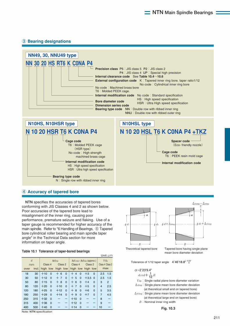
NTN Main Spindle Bearings
211
NTN specifies the accuracies of tapered boresconforming with JIS Classes 4 and 2 as shown below.Poor accuracies of the tapered bore lead tomisalignment of the inner ring, causing poorperformance, premature seizure and flaking. Use of ataper gauge is recommended for higher accuracy of themain spindle. Refer to "6 Handling of Bearings, ⑧ Taperedbore cylindrical roller bearing and main spindle taperangle" in the Technical Data section for moreinformation on taper angle.
③ Bearing designations
④ Accuracy of tapered bore
Precision class P5:JIS class 5 P2:JIS class 2 P4:JIS class 4 UP:Special high precision
Internal modification code No code:Standard specification HS:High speed specification HSR:Ultra High speed specificationBore diameter code
Bearing type code NN:Double row with ribbed inner ring NNU:Double row with ribbed outer ring
Dimension series code
External configuration code K:Tapered inner ring bore, taper ratio1/12 No code:Cylindrical inner ring boreNo code:Machined brass bore T6:Molded PEEK cage.
Internal clearance code See Table 10.4~10.6
Cage code T6:Molded PEEK cage (HSR type) No code:High strength machined brass cage
Internal modification code HS:High speed specification HSR:Ultra high speed specification
Bearing type code N:Single row with ribbed inner ring
NN 30 20 HS RT6 K C0NA P4
N 10 20 HSR T6 K C0NA P4 Spacer code (Eco- friendly nozzle)
Cage code T6:PEEK resin mold cage
Internal modification code
N 10 20 HSL T6 K C0NA P4 +TKZ
NN49, 30, NNU49 type
N10HS, N10HSR type N10HSL type
α α
φd+Δdmp
BB
φd1+Δd1mp
Δd1mp-Δdmp 2
φd1φd
Theoretical tapered bore Tapered bore having single plane mean bore diameter deviation
Tolerance of 1/12 taper angle 4˚46’18.8” +24” 0
α=2˚23’9.4”
d1=d+ B
Vdp:Single radial plane bore diameter variation Δdmp:Single plane mean bore diameter deviation
(at theoretical small end on tapered bore) Δd1mp:Single plane mean bore diameter deviation
(at theoretical large end on tapered bore) B:Nominal inner ring width
121
Fig. 10.3
d mm
Δdmp Δd1mp-Δdmp (approx.)
Vdp
maxover incl. high low high low
18
30
50
80
120
180
250
315
400
+10
+12
+15
+20
+25
+29
+32
+36
+40
0
0
0
0
0
0
0
0
0
+ 6
+ 7
+ 8
+10
+12
+14
-
-
-
0
0
0
0
0
0
-
-
-
+ 4
+ 5
+ 6
+ 7
+ 8
+ 9
+10
+12
+14
0
0
0
0
0
0
0
0
0
+3
+3.5
+4
+5
+6
+7
-
-
-
0
0
0
0
0
0
-
-
-
30
50
80
120
180
250
315
400
500
2.5
2.5
3
4
5
7
8
9
10
1.5
1.5
2
2.5
3.5
4.5
-
-
-
Note: NTN specification
Unit:μm
Class 4 Class 2
high low high low
Class 4 Class 2 Class 4 Class 2
Table 10.1 Tolerance of taper-bored bearings
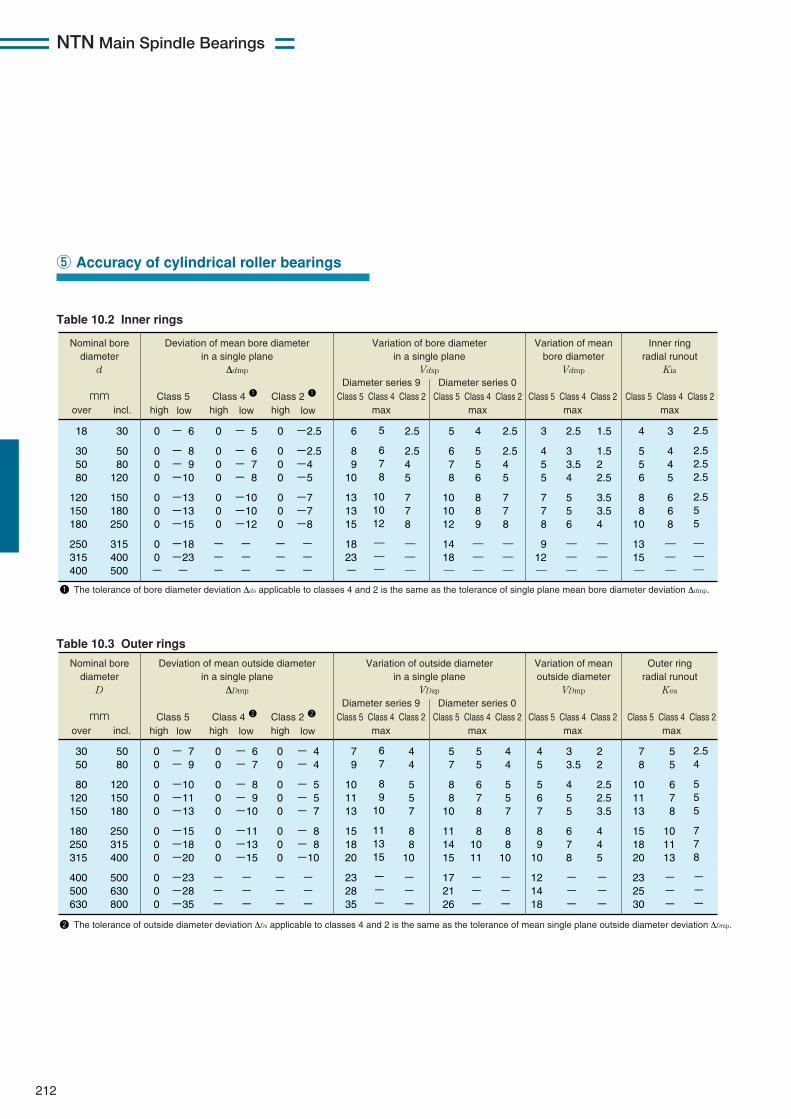
NTN Main Spindle Bearings
212
⑤ Accuracy of cylindrical roller bearings
Table 10.2 Inner rings
Table 10.3 Outer rings
Nominal bore diameter
d mm
Deviation of mean bore diameter in a single plane
Δdmp
Class 5 Class 4 1 Class 2 1
Variation of bore diameter in a single plane
Vdsp
Diameter series 9
18
30 50 80
120 150 180
250 315 400
30
50 80
120
150 180 250
315 400 500
0
0 0 0
0 0 0
0 0 -
- 6
- 8 - 9 -10
-13 -13 -15
-18 -23 -
0
0 0 0
0 0 0
- - -
- 5
- 6 - 7 - 8
-10 -10 -12
- - -
0
0 0 0
0 0 0
- - -
6
8 9
10
13 13 15
18 23 -
5
6 7 8
10 10 12
― ― ―
2.5
2.5 4 5
7 7 8
― ― ―
-2.5
-2.5 -4 -5
-7 -7 -8
- - -
over incl. high low
high low high low
5
6 7 8
10 10 12
14 18 ―
4
5 5 6
8 8 9
― ― ―
2.5
2.5 4 5
7 7 8
― ― ―
3
4 5 5
7 7 8
9 12 ―
2.5
3 3.5 4
5 5 6
― ― ―
1.5
1.5 2 2.5
3.5 3.5 4
― ― ―
4
5 5 6
8 8
10
13 15 ―
3
4 4 5
6 6 8
― ― ―
2.5
2.5 2.5 2.5
2.5 5 5
― ― ―
Diameter series 0
Variation of mean bore diameter
Vdmp
Inner ring radial runout
Kia
Class 5 Class 4 Class 2max
Class 5 Class 4 Class 2max
Class 5 Class 4 Class 2max
Class 5 Class 4 Class 2max
1 The tolerance of bore diameter deviation Δds applicable to classes 4 and 2 is the same as the tolerance of single plane mean bore diameter deviation Δdmp.
Nominal bore diameter
D mm
Deviation of mean outside diameter in a single plane
ΔDmp
Variation of outside diameter in a single plane
VDsp
30 50
80 120 150
180 250 315
400 500 630
50 80
120 150 180
250 315 400
500 630 800
0 0
0 0 0
0 0 0
0 0 0
- 7 - 9
-10 -11 -13
-15 -18 -20
-23 -28 -35
0 0
0 0 0
0 0 0
- - -
- 6 - 7
- 8 - 9 -10
-11 -13 -15
- - -
0 0
0 0 0
0 0 0
- - -
7 9
10 11 13
15 18 20
23 28 35
6 7
8 9
10
11 13 15
- - -
4 4
5 5 7
8 8
10
- - -
- 4 - 4
- 5 - 5 - 7
- 8 - 8 -10
- - -
5 7
8 8
10
11 14 15
17 21 26
5 5
6 7 8
8 10 11
- - -
4 4
5 5 7
8 8
10
- - -
4 5
5 6 7
8 9
10
12 14 18
3 3.5
4 5 5
6 7 8
- - -
2 2
2.5 2.5 3.5
4 4 5
- - -
7 8
10 11 13
15 18 20
23 25 30
5 5
6 7 8
10 11 13
- - -
2.5 4
5 5 5
7 7 8
- - -
Variation of mean outside diameter
VDmp
Outer ring radial runout
Kea
2 The tolerance of outside diameter deviation ΔDs applicable to classes 4 and 2 is the same as the tolerance of mean single plane outside diameter deviation ΔDmp.
Class 5 Class 4 2 Class 2 2Diameter series 9
over incl. high low high low high low
Diameter series 0Class 5 Class 4 Class 2
maxClass 5 Class 4 Class 2
maxClass 5 Class 4 Class 2
maxClass 5 Class 4 Class 2
maxC

NTN Main Spindle Bearings
213
Width deviation
ΔBs
Single bearing
Width variation
VBs
5
5 6 7
8 8
10
13 15 ―
1.5
1.5 1.5 2.5
2.5 4 5
― ― ―
2.5
3 4 4
5 5 6
― ― ―
0
0 0 0
0 0 0
0 0 ―
-120
-120 -150 -200
-250 -250 -300
-350 -400 ―
0
0 0 0
0 0 0
― ― ―
-120
-120 -150 -200
-250 -300 -350
― ― ―
high low high low
Class 5 Class 5Class 4 Class 4Class 2 Class 2max
Class 5 Class 4 Class 2max
Perpendicularity of inner ring face
with respect to the bore Sd
8
8 8 9
10 10 11
13 15 ―
1.5
1.5 1.5 2.5
2.5 4 5
― ― ―
4
4 5 5
6 6 7
― ― ―
Unit:μm
Width deviation
ΔCs
All classes
Width variation
VCs
5 6
8 8 8
10 11 13
15 18 20
1.5 1.5
2.5 2.5 2.5
4 5 7
- - -
2.5 3
4 5 5
7 7 8
- - -
Identical to ΔBs relative to d on the same bearing.
Perpendicularity of outer ring outside surface with respect to the face
SD
8 8
9 10 10
11 13 13
15 18 20
1.5 1.5
2.5 2.5 2.5
4 5 7
- - -
4 4
5 5 5
7 8
10
- - -
Unit:μm
Class 5 Class 4 Class 2max
Class 5 Class 4 Class 2max

NTN Main Spindle Bearings
214
■Non-interchangeable radial internal clearance Two types of radial internal clearance are available:
non-interchangeable radial internal clearance for whichthe combination of outer ring and inner ring cannot bechanged; and interchangeable radial internal clearancethat allows for different outer ring and inner ringcombination. The clearances listed are common toboth double-row and the single-row cylindrical roller
⑥ Radial internal clearance of cylindrical roller bearings
Table 10.4 Cylindrical bore bearings
Nominal bore diameter d mm
Unit:μm
over min max min max min maxincl.
Cylindrical bore bearing
C1NA C2NA NA 1
24 30 40
50 65 80
100 120 140
160 180 200
225 250 280
315 355 400 450
30 40 50
65 80
100
120 140 160
180 200 225
250 280 315
355 400 450 500
10 12 15
15 20 25
25 30 35
35 40 45
50 55 60
65 75 85 95
10 12 15
15 20 25
25 30 35
35 40 45
50 55 60
65 75 85 95
25 25 30
35 40 45
50 60 65
75 80 90
100 110 120
135 150 170 190
25 25 30
35 40 45
50 60 65
75 80 90
100 110 120
135 150 170 190
35 40 45
50 60 70
80 90
100
110 120 135
150 165 180
200 225 255 285
5 5 5
5 10 10
10 15 15
15 20 20
25 25 30
30 35 45 50
1 The code for normal internal clearance is “NA”. Ex: N1006HSNA Table 10.5 Tapered bore bearings
Nominal bore diameter d mm
Unit:μm
over min max min max min maxincl.
Tapered bore bearing
C9NA 2 C0NA 2 C1NA 2
24 30 40
50 65 80
100 120 140
160 180 200
225 250 280
315 355 400 450
30 40 50
65 80
100
120 140 160
180 200 225
250 280 315
355 400 450 500
10 12 15
15 20 25
25 30 35
35 40 45
50 55 60
65 75 85 95
10 10 10
10 15 20
20 25 30
30 30 35
40 40 45
45 50 60 70
20 20 20
20 30 35
35 40 45
45 50 55
65 65 75
75 90
100 115
10 12 15
15 20 25
25 30 35
35 40 45
50 55 60
65 75 85 95
25 25 30
35 40 45
50 60 65
75 80 90
100 110 120
135 150 170 190
min max
C2NA
25 25 30
35 40 45
50 60 65
75 80 90
100 110 120
135 150 170 190
35 40 45
50 60 70
80 90
100
110 120 135
150 165 180
200 225 255 285
min max
NA 1
40 45 50
55 70 80
95 105 115
125 140 155
170 185 205
225 255 285 315
50 55 65
75 90
105
120 135 150
165 180 200
215 240 265
295 330 370 410
5 5 5
5 10 10
10 15 15
15 20 20
25 25 30
30 35 45 50
1 The code for normal internal clearance is "NA". Ex: N1006HSKNA 2 Internal clearances C9NA, C0NA and C1NA apply to bearings of JIS class 5 or higher.
bearings. For machine components including high-precision machine tool main spindle, bearings with non-interchangeable radial internal clearance and a smallclearance range are used. If a double-low tapered borebearing is used and the desired mounted internalclearance is close to zero, use of clearance in the rangebetween C9NA and CINA is recommended. Cylindricalbore bearings with non-interchangeable radial internalclearance are also available. For details, contact NTNEngineering.
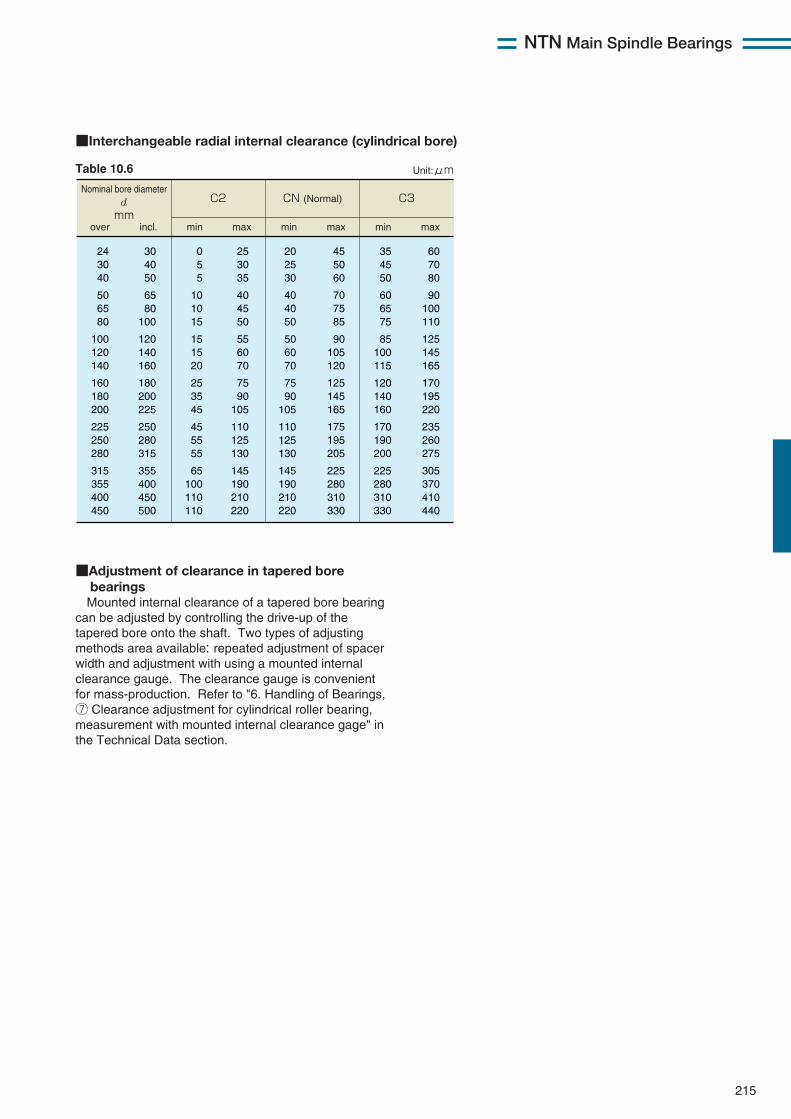
NTN Main Spindle Bearings
215
■Interchangeable radial internal clearance (cylindrical bore)
Table 10.6
Nominal bore diameter d mm
Unit:μm
over min max min max min maxincl.
C2 CN (Normal)
C3
24 30 40
50 65 80
100 120 140
160 180 200
225 250 280
315 355 400 450
30 40 50
65 80
100
120 140 160
180 200 225
250 280 315
355 400 450 500
0 5 5
10 10 15
15 15 20
25 35 45
45 55 55
65 100 110 110
25 30 35
40 45 50
55 60 70
75 90
105
110 125 130
145 190 210 220
20 25 30
40 40 50
50 60 70
75 90
105
110 125 130
145 190 210 220
45 50 60
70 75 85
90 105 120
125 145 165
175 195 205
225 280 310 330
35 45 50
60 65 75
85 100 115
120 140 160
170 190 200
225 280 310 330
60 70 80
90 100 110
125 145 165
170 195 220
235 260 275
305 370 410 440
■Adjustment of clearance in tapered bore bearingsMounted internal clearance of a tapered bore bearing
can be adjusted by controlling the drive-up of thetapered bore onto the shaft. Two types of adjustingmethods area available: repeated adjustment of spacerwidth and adjustment with using a mounted internalclearance gauge. The clearance gauge is convenientfor mass-production. Refer to "6. Handling of Bearings,⑦ Clearance adjustment for cylindrical roller bearing,measurement with mounted internal clearance gage" inthe Technical Data section.
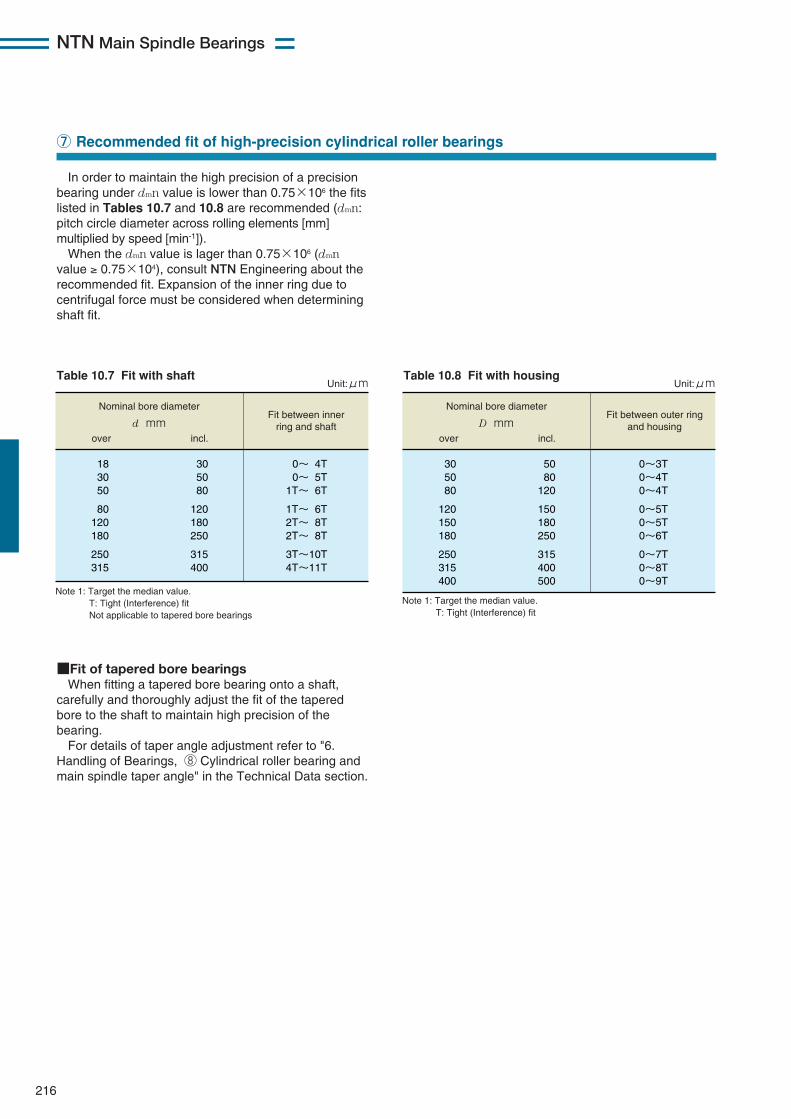
NTN Main Spindle Bearings
216
In order to maintain the high precision of a precisionbearing under dmn value is lower than 0.75×10⁶ the fitslisted in Tables 10.7 and 10.8 are recommended (dmn:pitch circle diameter across rolling elements [mm]multiplied by speed [min-1]).When the dmn value is lager than 0.75×10⁶ (dmn
value ≥ 0.75×10⁴), consult NTN Engineering about therecommended fit. Expansion of the inner ring due tocentrifugal force must be considered when determiningshaft fit.
■Fit of tapered bore bearingsWhen fitting a tapered bore bearing onto a shaft,
carefully and thoroughly adjust the fit of the taperedbore to the shaft to maintain high precision of thebearing.For details of taper angle adjustment refer to "6.
Handling of Bearings, ⑧ Cylindrical roller bearing andmain spindle taper angle" in the Technical Data section.
⑦ Recommended fit of high-precision cylindrical roller bearings
Nominal bore diameter
d mmFit between inner
ring and shaftFit between outer ring
and housingover incl.
18 30 50
80 120 180
250 315
30 50 80
120 180 250
315 400
0~ 4T 0~ 5T
1T~ 6T
1T~ 6T 2T~ 8T 2T~ 8T
3T~10T 4T~11T
Nominal bore diameter
D mmover incl.
30 50 80
120 150 180
250 315 400
50 80
120
150 180 250
315 400 500
0~3T 0~4T 0~4T
0~5T 0~5T 0~6T
0~7T 0~8T 0~9T
Note 1: Target the median value. T: Tight (Interference) fit Not applicable to tapered bore bearings
Note 1: Target the median value. T: Tight (Interference) fit
Unit:μm Unit:μmTable 10.7 Fit with shaft Table 10.8 Fit with housing
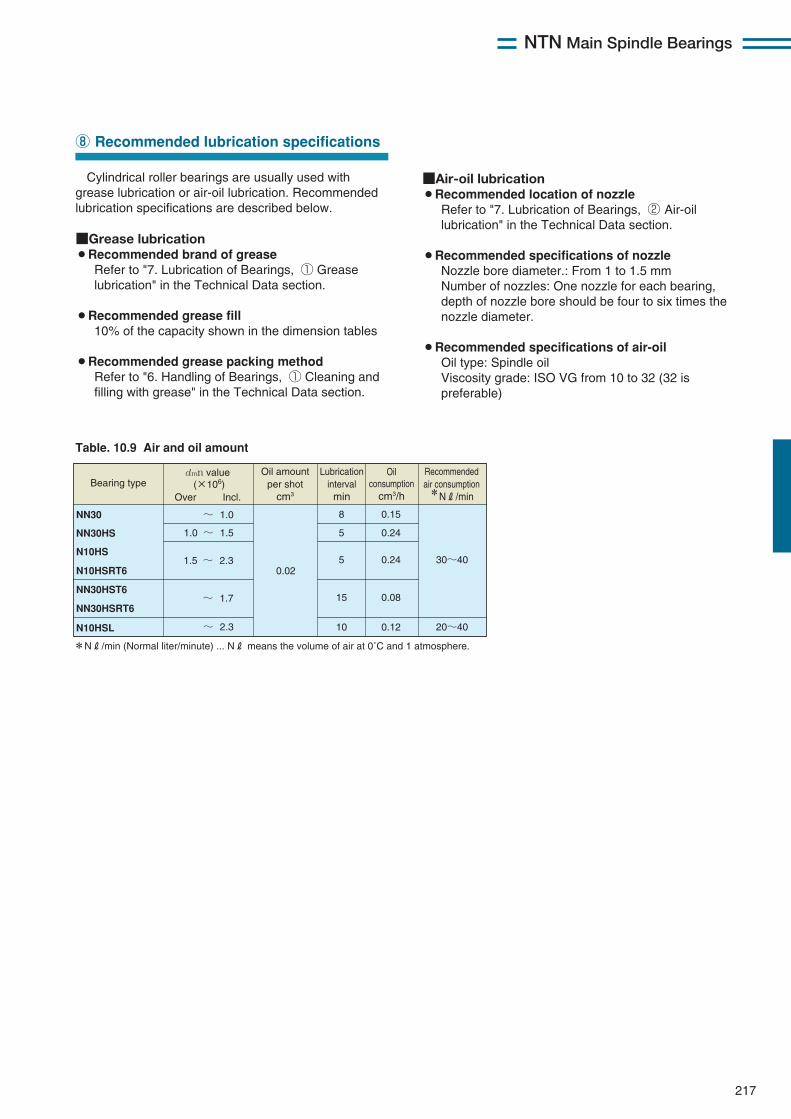
NTN Main Spindle Bearings
217
Cylindrical roller bearings are usually used withgrease lubrication or air-oil lubrication. Recommendedlubrication specifications are described below.
■Grease lubrication¡Recommended brand of grease
Refer to "7. Lubrication of Bearings, ① Greaselubrication" in the Technical Data section.
¡Recommended grease fill10% of the capacity shown in the dimension tables
¡Recommended grease packing methodRefer to "6. Handling of Bearings, ① Cleaning andfilling with grease" in the Technical Data section.
⑧ Recommended lubrication specifications
Table. 10.9 Air and oil amount
*NR/min (Normal liter/minute) ... NR means the volume of air at 0˚C and 1 atmosphere.
Recommended air consumption *NR/min
Bearing type
NN30
NN30HS
N10HS
N10HSRT6
NN30HST6
NN30HSRT6
N10HSL
dmn value (×106)
Over Incl.
~ 1.0
1.0 ~ 1.5
0.02
8
5
5
10
1.5 ~ 2.3 30~40
20~40 ~ 2.3
Oil amount per shot
cm3
Lubrication interval min
0.15
0.24
0.24
15 ~ 1.7 0.08
0.12
Oil consumption
cm3/h
■Air-oil lubrication¡Recommended location of nozzle
Refer to "7. Lubrication of Bearings, ② Air-oillubrication" in the Technical Data section.
¡Recommended specifications of nozzleNozzle bore diameter.: From 1 to 1.5 mmNumber of nozzles: One nozzle for each bearing,depth of nozzle bore should be four to six times thenozzle diameter.
¡Recommended specifications of air-oilOil type: Spindle oilViscosity grade: ISO VG from 10 to 32 (32 ispreferable)
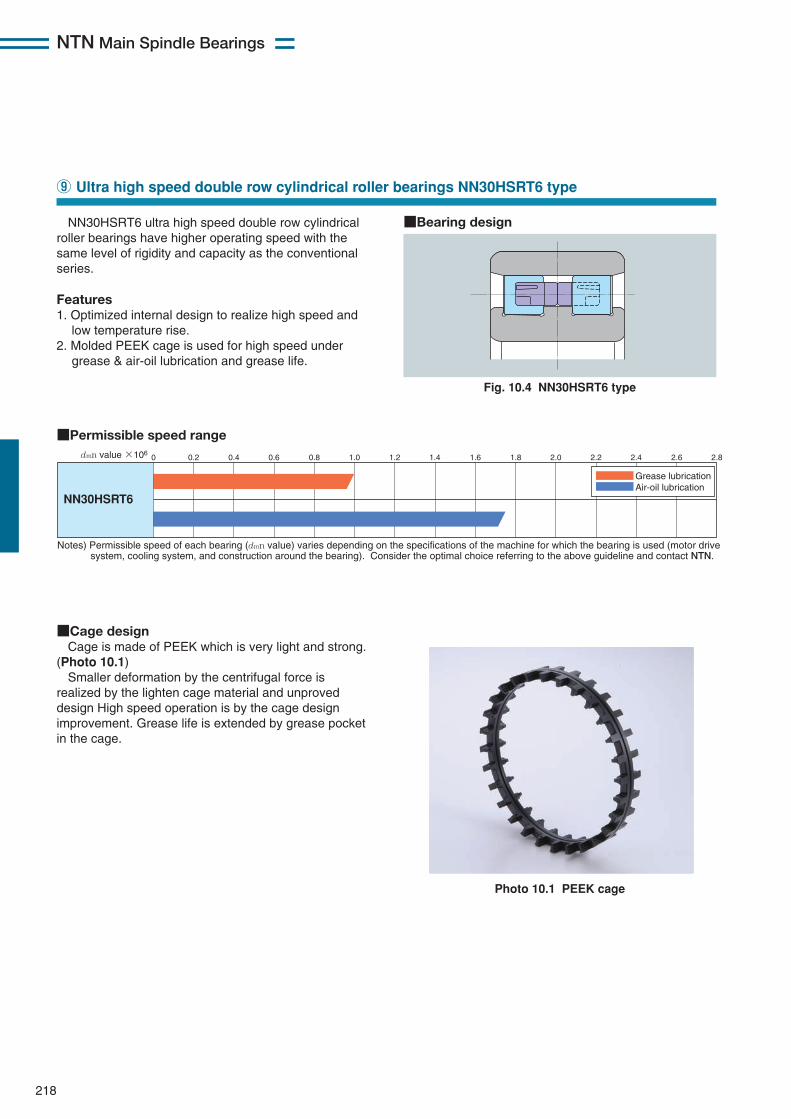
218
NTN Main Spindle Bearings
NN30HSRT6 ultra high speed double row cylindricalroller bearings have higher operating speed with thesame level of rigidity and capacity as the conventionalseries.
Features1. Optimized internal design to realize high speed and
low temperature rise.2. Molded PEEK cage is used for high speed under
grease & air-oil lubrication and grease life.
⑨ Ultra high speed double row cylindrical roller bearings NN30HSRT6 type
Fig. 10.4 NN30HSRT6 type
■Permissible speed range
NN30HSRT6
0 0.2 0.4 0.6 0.8 1.0 1.2 1.4 1.6 1.8 2.0 2.2 2.4 2.6 2.8
Grease lubrication Air-oil lubrication
Notes) Permissible speed of each bearing (dmn value) varies depending on the specifications of the machine for which the bearing is used (motor drive system, cooling system, and construction around the bearing). Consider the optimal choice referring to the above guideline and contact NTN.
dmn value ×106
■Bearing design
Photo 10.1 PEEK cage
■Cage designCage is made of PEEK which is very light and strong.
(Photo 10.1)Smaller deformation by the centrifugal force is
realized by the lighten cage material and unproveddesign High speed operation is by the cage designimprovement. Grease life is extended by grease pocketin the cage.
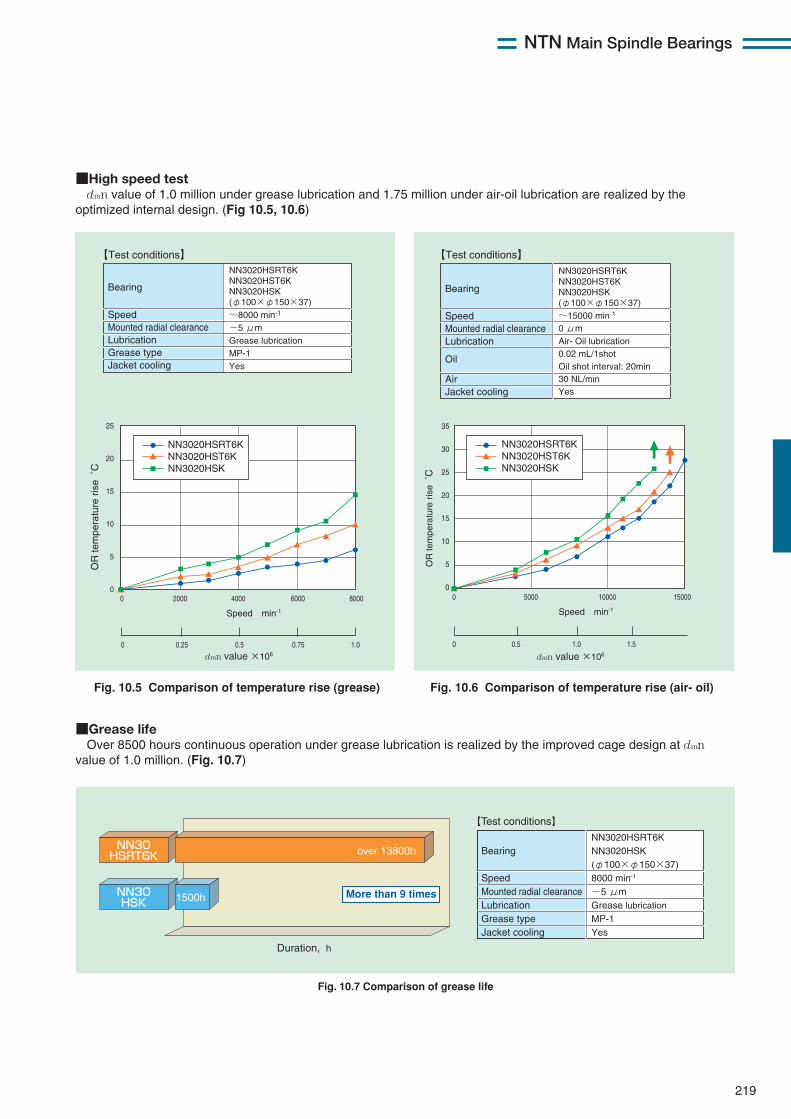
219
NTN Main Spindle Bearings
■High speed testdmn value of 1.0 million under grease lubrication and 1.75 million under air-oil lubrication are realized by the
optimized internal design. (Fig 10.5, 10.6)
■Grease lifeOver 8500 hours continuous operation under grease lubrication is realized by the improved cage design at dmn
value of 1.0 million. (Fig. 10.7)
Fig. 10.5 Comparison of temperature rise (grease) Fig. 10.6 Comparison of temperature rise (air- oil)
Bearing Speed Mounted radial clearance Lubrication Grease type Jacket cooling
NN3020HSRT6K NN3020HST6K NN3020HSK (φ100×φ150×37) ~8000 min-1 -5 μm Grease lubrication MP-1 Yes
【Test conditions】
Bearing Speed Mounted radial clearance Lubrication
Oil Air Jacket cooling
NN3020HSRT6K NN3020HST6K NN3020HSK (φ100×φ150×37) ~15000 min-1 0 μm Air- Oil lubrication 0.02 mL/1shot Oil shot interval: 20min 30 NL/min Yes
【Test conditions】
0 0.25 0.5 0.75 1.0
0 2000 4000 6000 8000
25
20
15
10
5
0
Speed min-1
dmn value ×106
OR
tem
pera
ture
ris
e ˚
C
Speed min-1
0 1.00.5 1.5
dmn value ×106
OR
tem
pera
ture
ris
e ˚
C
0 5000 10000 15000
35
30
25
20
15
10
5
0
NN3020HSRT6K NN3020HST6K NN3020HSK
NN3020HSRT6K NN3020HST6K NN3020HSK
Bearing Speed Mounted radial clearance Lubrication Grease type Jacket cooling
NN3020HSRT6K NN3020HSK (φ100×φ150×37) 8000 min-1 -5 μm Grease lubrication MP-1 Yes
【Test conditions】
Duration, h
over 13800h
1500h
NN30 HSRT6K
NN30 HSK
More than 9 times
Fig. 10.7 Comparison of grease life
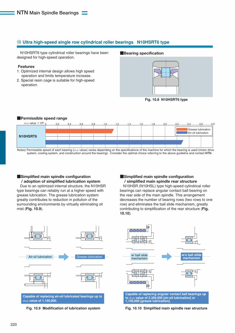
NTN Main Spindle Bearings
220
N10HSRT6 type cylindrical roller bearings have beendesigned for high-speed operation.
Features1. Optimized internal design allows high speed
operation and limits temperature increase.2. Special resin cage is suitable for high-speed
operation.
!0 Ultra high-speed single row cylindrical roller bearings N10HSRT6 type
Fig. 10.8 N10HSRT6 type
■Permissible speed range
N10HSRT6
0 0.2 0.4 0.6 0.8 1.0 1.2 1.4 1.6 1.8 2.0 2.2 2.4 2.6 2.8
Grease lubrication Air-oil lubrication
Notes) Permissible speed of each bearing (dmn value) varies depending on the specifications of the machine for which the bearing is used (motor drive system, cooling system, and construction around the bearing). Consider the optimal choice referring to the above guideline and contact NTN.
dmn value ×106
■Bearing specification
Fig. 10.9 Modification of lubrication system
■Simplified main spindle configuration/ adoption of simplified lubrication systemDue to an optimized internal structure, the N10HSR
type bearings can reliably run at a higher speed withgrease lubrication. The grease lubrication systemgreatly contributes to reduction in pollution of thesurrounding environments by virtually eliminating oilmist (Fig. 10.9).
■Simplified main spindle configuration/ simplified main spindle rear structureN10HSR (N10HSL) type high-speed cylindrical roller
bearings can replace angular contact ball bearing onthe rear side of the main spindle. This arrangementdecreases the number of bearing rows (two rows to onerow) and eliminates the ball slide mechanism, greatlycontributing to simplification of the rear structure (Fig.10.10).
Air-oil lubrication Grease lubrication
Capable of replacing air-oil lubricated bearings up to dmn value of 1,150,000.
Fig. 10.10 Simplified main spindle rear structure
w/ ball slide mechanism
w/o ball slide mechanism
Capable of replacing angular contact ball bearings up to dmn value of 2,300,000 [air-oil lubrication] or 1,150,000 [grease lubrication].
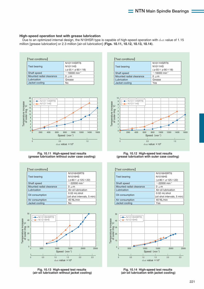
NTN Main Spindle Bearings
221
High-speed operation test with grease lubricationDue to an optimized internal design, the N10HSR type is capable of high-speed operation with dmn value of 1.15
million [grease lubrication] or 2.3 million [air-oil lubrication] (Figs. 10.11, 10.12, 10.13, 10.14).
Fig. 10.11 High-speed test results (grease lubrication without outer case cooling)
Fig. 10.12 High-speed test results (grease lubrication with outer case cooling)
Fig. 10.13 High-speed test results (air-oil lubrication without jacket cooling)
Fig. 10.14 High-speed test results (air-oil lubrication with jacket cooling)
0 0.5 1.0
0 2000 6000 8000 10000 12000 14000 160004000
20
18
16
14
12
10
8
6
4
2
0
Speed(min-1)
dmn value ×106
Tem
pera
ture
incr
ease
of
out
er r
ing
˚C
Tem
pera
ture
incr
ease
of
out
er r
ing
˚C
Tem
pera
ture
incr
ease
of
out
er r
ing
˚C
Tem
pera
ture
incr
ease
of
out
er r
ing
˚C
Test bearing Shaft speed Mounted radial clearance Lubrication Jacket cooling
N1011HSRT6 N1011HS (φ55×φ90×18) ~16000 min-1
0 μm Grease No
【Test conditions】
Test bearing Shaft speed Mounted radial clearance Lubrication Jacket cooling
【Test conditions】
N1011HSN1011HSRT6
0 0.5 1.0 1.5 2.0 2.5
0 5000 15000 20000 2500010000
50
40
30
20
10
0
Speed(min-1)
dmn value ×106
Test bearing Shaft speed Mounted radial clearance Lubrication
Oil consumption Air consumption Jacket cooling
N1016HSRT6 N1016HS (φ80×φ125×22) ~22000 min-1
0 μm Air-oil lubrication 0.02 mL/shot
(oil shot intervals, 5 min) 40 NL/min No
【Test conditions】
N1016HSN1016HSRT6
0 0.5 1.0 1.5 2.0 2.5
0 5000 15000 20000 2500010000
50
40
30
20
10
0
Speed(min-1)
dmn value ×106
Test bearing Shaft speed Mounted radial clearance Lubrication
Oil consumption Air consumption Jacket cooling
N1016HSRT6 N1016HS (φ80×φ125×22) ~22000 min-1
0 μm Air-oil lubrication 0.02 mL/shot
(oil shot intervals, 5 min) 40 NL/min Yes
【Test conditions】
N1016HSN1016HSRT6
0 0.5 1.0
0 2000 6000 8000 10000 12000 14000 160004000
10
9
8
7
6
5
4
3
2
1
0
Speed(min-1)
dmn value ×106
N1011HSRT6 N1011HS (φ55×φ90×18) ~16000 min-1 0 μm Grease Yes
N1011HSN1011HSRT6

NTN Main Spindle Bearings
The eco-friendly air-oil lubricated N10HSLT6 typewas developed by applying NTN's unique eco-conscious technology to the proven N10HSRT6 typebearing design. The N10HSLT6 type boasts limitedemission of oil mist and reduced air and oilconsumption. This improves operating environments,saves energy while allowing higher-speed machiningoperation.
■Features1. Optimized internal design allows high speed
operation and limits temperature increase.2. Adoption of the eco-friendly nozzle design has led to:
Lower noise level (up to 7 dBA)50% reduction in air consumption50% reduction in oil consumption.
222
!1 Eco-friendly air-oil lubricated cylindrical roller bearings N10HSLT6 type
Fig. 10.15 N10HSLT6 type
■Permissible speed range
N10HSLT6
0 0.2 0.4 0.6 0.8 1.0 1.2 1.4 1.6 1.8 2.0 2.2 2.4 2.6 2.8
Notes) Permissible speed of each bearing (dmn value) varies depending on the specifications of the machine for which the bearing is used (motor drive system, cooling system, and construction around the bearing). Consider the optimal choice referring to the above guideline and contact NTN.
dmn value ×106
N10HS type (conventional bearing type)
Air-oil
ULTAGE N10HSLT6 type
Air-oil Eco-friendly nozzle
Internal specification of N10HSRT6 type Eco-friendly specification
NOTE) The N10HSLT6 type is delivered as packed together with the spacer with the eco-friendly nozzle. The bearing type code N10HSLT6 represents the bearing proper, while a spacer code stands for an eco-friendly nozzle proper or a spacer having a built-in nozzle. For more details, see “3 Bearing Designations”.
■Bearing specification
■High-speed running testEven with decreased air consumption and oil consumption, the N10HSL type bearings can reliably operate at high
speed of dmn 2.3×10⁶ (Fig. 10.16, 10.17).
Fig. 10.16 Hgh-speed test results (without Jacket cooling)
Fig. 10.17 High-speed test results (with Jacket cooling)
0 0.5 1.51.0 2.0 2.5
0 5000 15000 20000 2500010000
50
40
30
20
10
0
Shaft speed(min-1)
dmn value×106
Tem
pera
ture
incr
ease
of
out
er r
ing
˚C
Tem
pera
ture
incr
ease
of
out
er r
ing
˚C
Test bearing Shaft speed Mounted radial clearance Oil consumption Air consumption Jacket cooling
N1016HSLT6 N1016HS (φ80×φ125×22) ~22000 min-1 0 μm 0.02 mL/shotN1016HS N1016HSL N1016HS N1016HSL No
5 min intervals 10 min intervals 40 NL/min 20 NL/min
【Test conditions】
N1016HSN1016HSLT6
0 0.5 1.51.0 2.0 2.5
0 5000 15000 20000 2500010000
50
40
30
20
10
0
Shaft speed(min-1)
dmn value×106
Test bearing Shaft speed Mounted radial clearance Oil consumption Air consumption Jacket cooling
N1016HSLT6 N1016HS (φ80×φ125×22) ~23000 min-1 0 μm 0.02 mL/shotN1016HS N1016HSL N1016HS N1016HSL Yes
5 min intervals 10 min intervals 40 NL/min 20 NL/min
【Test conditions】
N1016HSN1016HSLT6
NTN Main Spindle Bearings
223
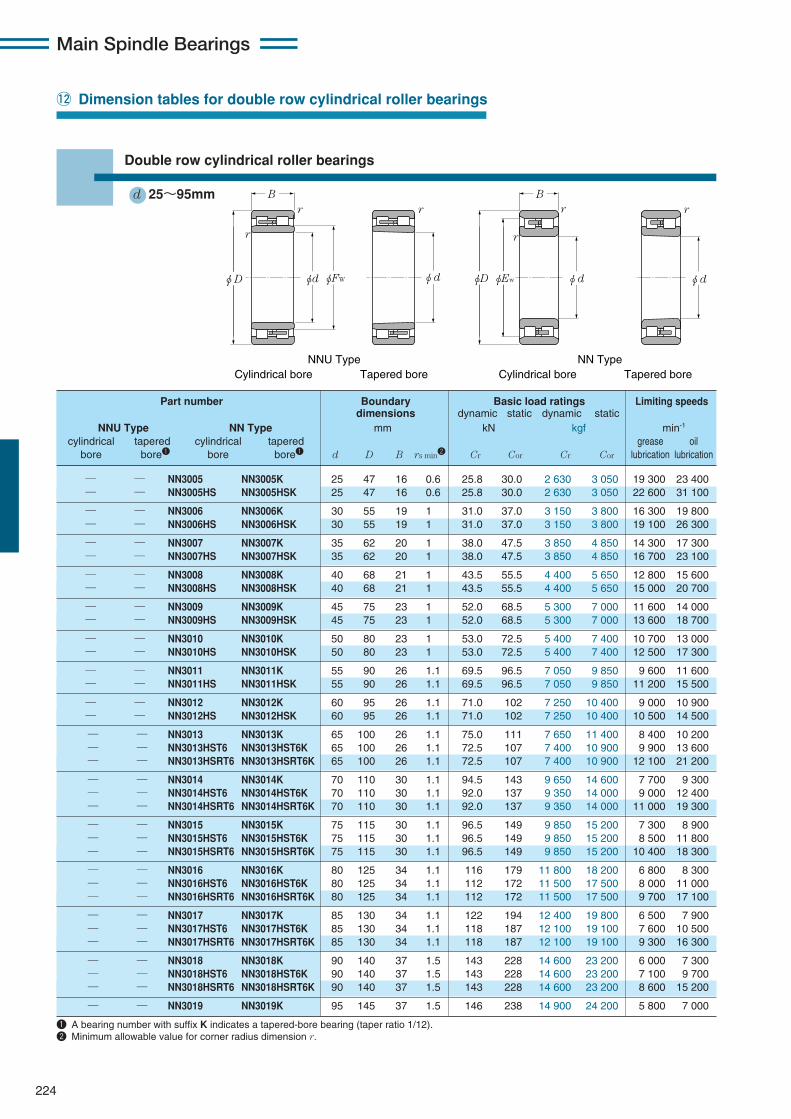
Main Spindle Bearings
224
!2 Dimension tables for double row cylindrical roller bearings
Double row cylindrical roller bearings
d 25〜95mm
— — NN3005 NN3005K 25 47 16 0.6 25.8 30.0 2 630 3 050 19 300 23 400— — NN3005HS NN3005HSK 25 47 16 0.6 25.8 30.0 2 630 3 050 22 600 31 100
— — NN3006 NN3006K 30 55 19 1 31.0 37.0 3 150 3 800 16 300 19 800— — NN3006HS NN3006HSK 30 55 19 1 31.0 37.0 3 150 3 800 19 100 26 300
— — NN3007 NN3007K 35 62 20 1 38.0 47.5 3 850 4 850 14 300 17 300— — NN3007HS NN3007HSK 35 62 20 1 38.0 47.5 3 850 4 850 16 700 23 100
— — NN3008 NN3008K 40 68 21 1 43.5 55.5 4 400 5 650 12 800 15 600— — NN3008HS NN3008HSK 40 68 21 1 43.5 55.5 4 400 5 650 15 000 20 700
— — NN3009 NN3009K 45 75 23 1 52.0 68.5 5 300 7 000 11 600 14 000— — NN3009HS NN3009HSK 45 75 23 1 52.0 68.5 5 300 7 000 13 600 18 700
— — NN3010 NN3010K 50 80 23 1 53.0 72.5 5 400 7 400 10 700 13 000— — NN3010HS NN3010HSK 50 80 23 1 53.0 72.5 5 400 7 400 12 500 17 300
— — NN3011 NN3011K 55 90 26 1.1 69.5 96.5 7 050 9 850 9 600 11 600— — NN3011HS NN3011HSK 55 90 26 1.1 69.5 96.5 7 050 9 850 11 200 15 500
— — NN3012 NN3012K 60 95 26 1.1 71.0 102 7 250 10 400 9 000 10 900— — NN3012HS NN3012HSK 60 95 26 1.1 71.0 102 7 250 10 400 10 500 14 500
— — NN3013 NN3013K 65 100 26 1.1 75.0 111 7 650 11 400 8 400 10 200— — NN3013HST6 NN3013HST6K 65 100 26 1.1 72.5 107 7 400 10 900 9 900 13 600— — NN3013HSRT6 NN3013HSRT6K 65 100 26 1.1 72.5 107 7 400 10 900 12 100 21 200
— — NN3014 NN3014K 70 110 30 1.1 94.5 143 9 650 14 600 7 700 9 300— — NN3014HST6 NN3014HST6K 70 110 30 1.1 92.0 137 9 350 14 000 9 000 12 400— — NN3014HSRT6 NN3014HSRT6K 70 110 30 1.1 92.0 137 9 350 14 000 11 000 19 300
— — NN3015 NN3015K 75 115 30 1.1 96.5 149 9 850 15 200 7 300 8 900— — NN3015HST6 NN3015HST6K 75 115 30 1.1 96.5 149 9 850 15 200 8 500 11 800— — NN3015HSRT6 NN3015HSRT6K 75 115 30 1.1 96.5 149 9 850 15 200 10 400 18 300
— — NN3016 NN3016K 80 125 34 1.1 116 179 11 800 18 200 6 800 8 300— — NN3016HST6 NN3016HST6K 80 125 34 1.1 112 172 11 500 17 500 8 000 11 000— — NN3016HSRT6 NN3016HSRT6K 80 125 34 1.1 112 172 11 500 17 500 9 700 17 100
— — NN3017 NN3017K 85 130 34 1.1 122 194 12 400 19 800 6 500 7 900— — NN3017HST6 NN3017HST6K 85 130 34 1.1 118 187 12 100 19 100 7 600 10 500— — NN3017HSRT6 NN3017HSRT6K 85 130 34 1.1 118 187 12 100 19 100 9 300 16 300
— — NN3018 NN3018K 90 140 37 1.5 143 228 14 600 23 200 6 000 7 300— — NN3018HST6 NN3018HST6K 90 140 37 1.5 143 228 14 600 23 200 7 100 9 700— — NN3018HSRT6 NN3018HSRT6K 90 140 37 1.5 143 228 14 600 23 200 8 600 15 200
— — NN3019 NN3019K 95 145 37 1.5 146 238 14 900 24 200 5 800 7 000
Part number Boundary Basic load ratings Limiting speedsdimensions dynamic static dynamic static
NNU Type NN Type mm kN kgf min-1
cylindrical tapered cylindrical tapered grease oilbore bore1 bore bore1 d D B rs min2 Cr Cor Cr Cor lubrication lubrication
1 A bearing number with suffix K indicates a tapered-bore bearing (taper ratio 1/12).2 Minimum allowable value for corner radius dimension r.
r r r
r
Br
r
φdφd φEwφD
B
φd φd φFWφD
NNU Type Cylindrical bore Tapered bore
NN TypeCylindrical bore Tapered bore

225
Main Spindle Bearings
Dynamic equivalentradial loadPr=Fr
Static equivalentradial loadPor=Fr
− 41.3 29 30 − − − 43 42 0.6 − − 0.124 0.121 3.72− 41.3 29 30 − − − 43 42 0.6 − − 0.124 0.121 3.72
− 48.5 35 36.5 − − − 50 49 1 − − 0.199 0.193 6.38− 48.5 35 36.5 − − − 50 49 1 − − 0.199 0.193 6.38
− 55 40 41.5 − − − 57 56 1 − − 0.242 0.235 8.09− 55 40 41.5 − − − 57 56 1 − − 0.242 0.235 8.09
− 61 45 47 − − − 63 62 1 − − 0.312 0.303 9.68− 61 45 47 − − − 63 62 1 − − 0.312 0.303 9.68
− 67.5 50 52 − − − 70 69 1 − − 0.405 0.393 13.3− 67.5 50 52 − − − 70 69 1 − − 0.405 0.393 13.3
− 72.5 55 57 − − − 75 74 1 − − 0.433 0.419 14.6− 72.5 55 57 − − − 75 74 1 − − 0.433 0.419 14.6
− 81 61.5 63.5 − − − 83.5 82 1 − − 0.651 0.631 20.5− 81 61.5 63.5 − − − 83.5 82 1 − − 0.651 0.631 20.5
− 86.1 66.5 68.5 − − − 88.5 87 1 − − 0.704 0.683 21.1− 86.1 66.5 68.5 − − − 88.5 87 1 − − 0.704 0.683 21.1
— 91 71.5 73.5 — — — 93.5 92 1 — — 0.76 0.74 22.2— 91 71.5 73.5 — — — 93.5 92 1 — — 0.69 0.66 21.4— 91 71.5 73.5 — — — 93.5 92 1 — — 0.69 0.66 21.4
— 100 76.5 79 — — — 103.5 101 1 — — 1.04 1.01 33.0— 100 76.5 79 — — — 103.5 101 1 — — 0.99 0.96 30.4— 100 76.5 79 — — — 103.5 101 1 — — 0.99 0.96 30.4
— 105 81.5 84 — — — 108.5 106 1 — — 1.14 1.11 35.0— 105 81.5 84 — — — 108.5 106 1 — — 1.05 1.02 31.2— 105 81.5 84 — — — 108.5 106 1 — — 1.05 1.02 31.2
— 113 86.5 89.5 — — — 118.5 114 1 — — 1.52 1.47 45.0— 113 86.5 89.5 — — — 118.5 114 1 — — 1.43 1.38 43.0— 113 86.5 89.5 — — — 118.5 114 1 — — 1.43 1.38 43.0
— 118 91.5 84.5 — — — 123.5 119 1 — — 1.61 1.56 48.8— 118 91.5 84.5 — — — 123.5 119 1 — — 1.51 1.46 44.4— 118 91.5 84.5 — — — 123.5 119 1 — — 1.51 1.46 44.4
— 127 98 101 — — — 132 129 1.5 — — 2.07 2.01 64.1— 127 98 101 — — — 132 129 1.5 — — 1.97 1.91 57.6— 127 98 101 — — — 132 129 1.5 — — 1.97 1.91 57.6
— 132 103 106 — — — 137 134 1.5 — — 2.17 2.10 67.0
Dimensions Abutment and fillet dimensions Mass Internalkg (approx.) free space
mm mm NNU Type NN Type cm3
da db dc dd Da Db ras cylindrical tapered cylindrical tapered NNFw Ew min min max min max max min max bore bore bore bore Type
ra
ra ra
ra
ra
φdbφdaφDb φDb φdaφDbφdaφdc φddφDa
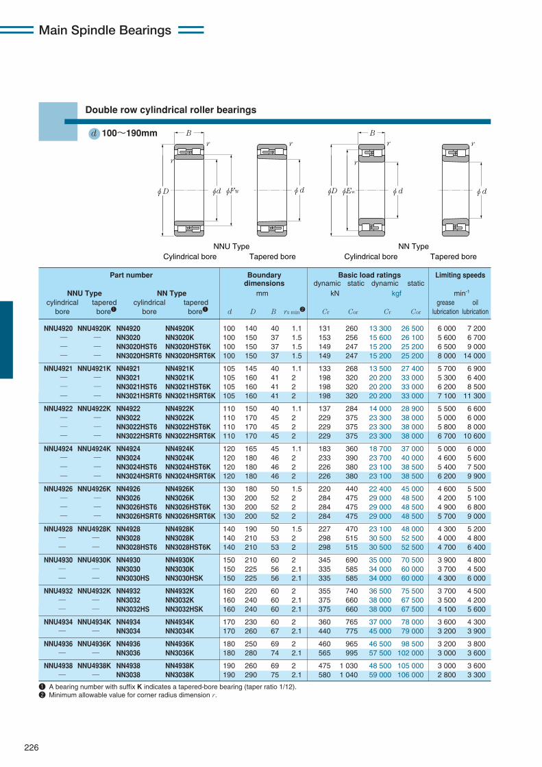
Main Spindle Bearings
226
NNU4920 NNU4920K NN4920 NN4920K 100 140 40 1.1 131 260 13 300 26 500 6 000 7 200— — NN3020 NN3020K 100 150 37 1.5 153 256 15 600 26 100 5 600 6 700— — NN3020HST6 NN3020HST6K 100 150 37 1.5 149 247 15 200 25 200 6 500 9 000— — NN3020HSRT6 NN3020HSRT6K 100 150 37 1.5 149 247 15 200 25 200 8 000 14 000
NNU4921 NNU4921K NN4921 NN4921K 105 145 40 1.1 133 268 13 500 27 400 5 700 6 900— — NN3021 NN3021K 105 160 41 2 198 320 20 200 33 000 5 300 6 400— — NN3021HST6 NN3021HST6K 105 160 41 2 198 320 20 200 33 000 6 200 8 500— — NN3021HSRT6 NN3021HSRT6K 105 160 41 2 198 320 20 200 33 000 7 100 11 300
NNU4922 NNU4922K NN4922 NN4922K 110 150 40 1.1 137 284 14 000 28 900 5 500 6 600— — NN3022 NN3022K 110 170 45 2 229 375 23 300 38 000 5 000 6 000— — NN3022HST6 NN3022HST6K 110 170 45 2 229 375 23 300 38 000 5 800 8 000— — NN3022HSRT6 NN3022HSRT6K 110 170 45 2 229 375 23 300 38 000 6 700 10 600
NNU4924 NNU4924K NN4924 NN4924K 120 165 45 1.1 183 360 18 700 37 000 5 000 6 000— — NN3024 NN3024K 120 180 46 2 233 390 23 700 40 000 4 600 5 600— — NN3024HST6 NN3024HST6K 120 180 46 2 226 380 23 100 38 500 5 400 7 500— — NN3024HSRT6 NN3024HSRT6K 120 180 46 2 226 380 23 100 38 500 6 200 9 900
NNU4926 NNU4926K NN4926 NN4926K 130 180 50 1.5 220 440 22 400 45 000 4 600 5 500— — NN3026 NN3026K 130 200 52 2 284 475 29 000 48 500 4 200 5 100— — NN3026HST6 NN3026HST6K 130 200 52 2 284 475 29 000 48 500 4 900 6 800— — NN3026HSRT6 NN3026HSRT6K 130 200 52 2 284 475 29 000 48 500 5 700 9 000
NNU4928 NNU4928K NN4928 NN4928K 140 190 50 1.5 227 470 23 100 48 000 4 300 5 200— — NN3028 NN3028K 140 210 53 2 298 515 30 500 52 500 4 000 4 800— — NN3028HST6 NN3028HST6K 140 210 53 2 298 515 30 500 52 500 4 700 6 400
NNU4930 NNU4930K NN4930 NN4930K 150 210 60 2 345 690 35 000 70 500 3 900 4 800— — NN3030 NN3030K 150 225 56 2.1 335 585 34 000 60 000 3 700 4 500— — NN3030HS NN3030HSK 150 225 56 2.1 335 585 34 000 60 000 4 300 6 000
NNU4932 NNU4932K NN4932 NN4932K 160 220 60 2 355 740 36 500 75 500 3 700 4 500— — NN3032 NN3032K 160 240 60 2.1 375 660 38 000 67 500 3 500 4 200— — NN3032HS NN3032HSK 160 240 60 2.1 375 660 38 000 67 500 4 100 5 600
NNU4934 NNU4934K NN4934 NN4934K 170 230 60 2 360 765 37 000 78 000 3 600 4 300— — NN3034 NN3034K 170 260 67 2.1 440 775 45 000 79 000 3 200 3 900
NNU4936 NNU4936K NN4936 NN4936K 180 250 69 2 460 965 46 500 98 500 3 200 3 800— — NN3036 NN3036K 180 280 74 2.1 565 995 57 500 102 000 3 000 3 600
NNU4938 NNU4938K NN4938 NN4938K 190 260 69 2 475 1 030 48 500 105 000 3 000 3 600— — NN3038 NN3038K 190 290 75 2.1 580 1 040 59 000 106 000 2 800 3 300
Part number Boundary Basic load ratings Limiting speedsdimensions dynamic static dynamic static
NNU Type NN Type mm kN kgf min-1
cylindrical tapered cylindrical tapered grease oilbore bore1 bore bore1 d D B rs min2 Cr Cor Cr Cor lubrication lubrication
1 A bearing number with suffix K indicates a tapered-bore bearing (taper ratio 1/12).2 Minimum allowable value for corner radius dimension r.
Double row cylindrical roller bearings
d 100〜190mmr r r
r
Br
r
φdφd φEwφD
B
φd φd φFWφD
NNU Type Cylindrical bore Tapered bore
NN TypeCylindrical bore Tapered bore
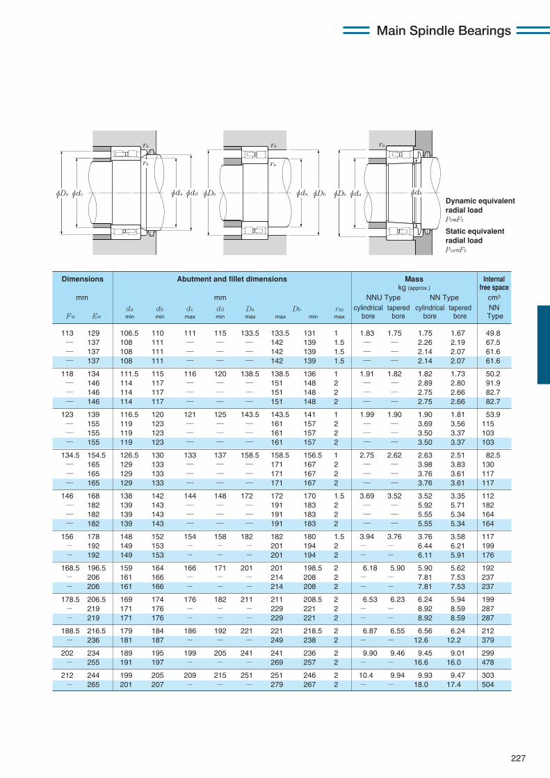
227
Main Spindle Bearings
Dynamic equivalentradial loadPr=Fr
Static equivalentradial loadPor=Fr
113 129 106.5 110 111 115 133.5 133.5 131 1 1.83 1.75 1.75 1.67 49.8— 137 108 111 — — — 142 139 1.5 — — 2.26 2.19 67.5— 137 108 111 — — — 142 139 1.5 — — 2.14 2.07 61.6— 137 108 111 — — — 142 139 1.5 — — 2.14 2.07 61.6
118 134 111.5 115 116 120 138.5 138.5 136 1 1.91 1.82 1.82 1.73 50.2— 146 114 117 — — — 151 148 2 — — 2.89 2.80 91.9— 146 114 117 — — — 151 148 2 — — 2.75 2.66 82.7— 146 114 117 — — — 151 148 2 — — 2.75 2.66 82.7
123 139 116.5 120 121 125 143.5 143.5 141 1 1.99 1.90 1.90 1.81 53.9— 155 119 123 — — — 161 157 2 — — 3.69 3.56 115— 155 119 123 — — — 161 157 2 — — 3.50 3.37 103— 155 119 123 — — — 161 157 2 — — 3.50 3.37 103
134.5 154.5 126.5 130 133 137 158.5 158.5 156.5 1 2.75 2.62 2.63 2.51 82.5— 165 129 133 — — — 171 167 2 — — 3.98 3.83 130— 165 129 133 — — — 171 167 2 — — 3.76 3.61 117— 165 129 133 — — — 171 167 2 — — 3.76 3.61 117
146 168 138 142 144 148 172 172 170 1.5 3.69 3.52 3.52 3.35 112— 182 139 143 — — — 191 183 2 — — 5.92 5.71 182— 182 139 143 — — — 191 183 2 — — 5.55 5.34 164— 182 139 143 — — — 191 183 2 — — 5.55 5.34 164
156 178 148 152 154 158 182 182 180 1.5 3.94 3.76 3.76 3.58 117− 192 149 153 − − − 201 194 2 − − 6.44 6.21 199− 192 149 153 − − − 201 194 2 − − 6.11 5.91 176
168.5 196.5 159 164 166 171 201 201 198.5 2 6.18 5.90 5.90 5.62 192− 206 161 166 − − − 214 208 2 − − 7.81 7.53 237− 206 161 166 − − − 214 208 2 − − 7.81 7.53 237
178.5 206.5 169 174 176 182 211 211 208.5 2 6.53 6.23 6.24 5.94 199− 219 171 176 − − − 229 221 2 − − 8.92 8.59 287− 219 171 176 − − − 229 221 2 − − 8.92 8.59 287
188.5 216.5 179 184 186 192 221 221 218.5 2 6.87 6.55 6.56 6.24 212− 236 181 187 − − − 249 238 2 − − 12.6 12.2 379
202 234 189 195 199 205 241 241 236 2 9.90 9.46 9.45 9.01 299− 255 191 197 − − − 269 257 2 − − 16.6 16.0 478
212 244 199 205 209 215 251 251 246 2 10.4 9.94 9.93 9.47 303− 265 201 207 − − − 279 267 2 − − 18.0 17.4 504
Dimensions Abutment and fillet dimensions Mass Internalkg (approx.) free space
mm mm NNU Type NN Type cm3
da db dc dd Da Db ras cylindrical tapered cylindrical tapered NNFw Ew min min max min max max min max bore bore bore bore Type
ra
ra ra
ra
ra
φdbφdaφDb φDb φdaφDbφdaφdc φddφDa
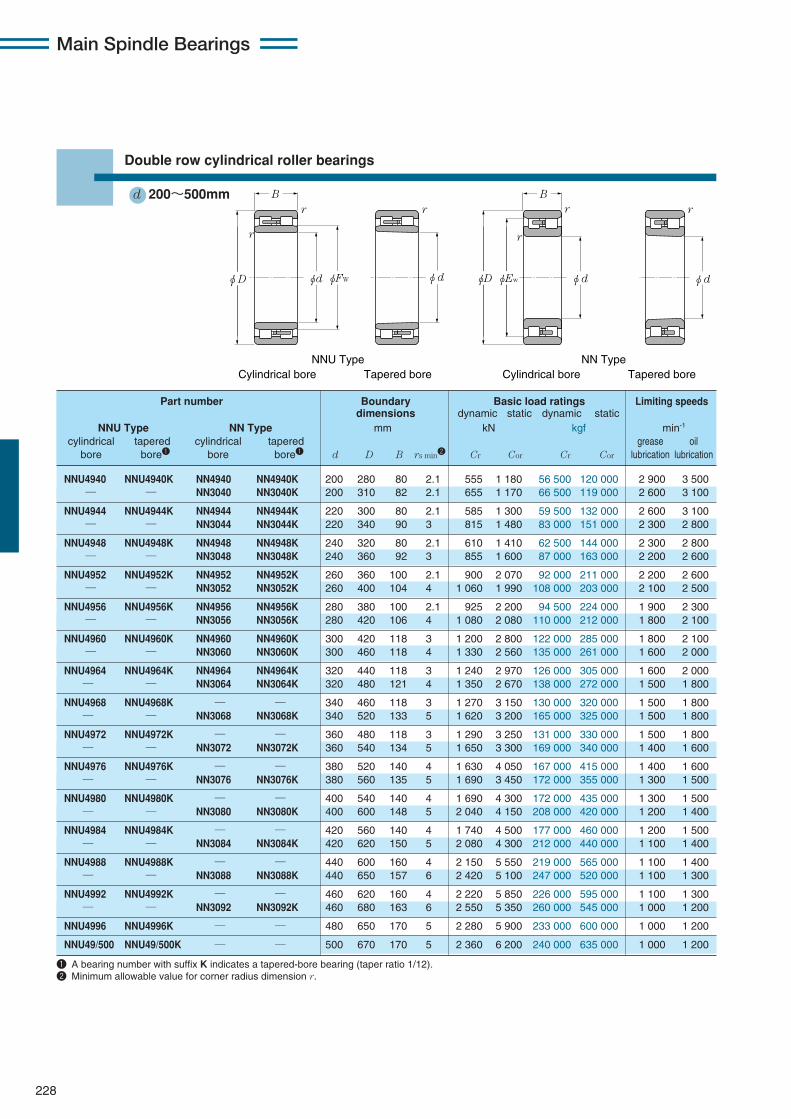
Main Spindle Bearings
228
Part number Boundary Basic load ratings Limiting speedsdimensions dynamic static dynamic static
NNU Type NN Type mm kN kgf min-1
cylindrical tapered cylindrical tapered grease oilbore bore1 bore bore1 d D B rs min2 Cr Cor Cr Cor lubrication lubrication
1 A bearing number with suffix K indicates a tapered-bore bearing (taper ratio 1/12).2 Minimum allowable value for corner radius dimension r.
r r r
r
Br
r
φdφd φEwφD
B
φd φd φFWφD
NNU Type Cylindrical bore Tapered bore
NN TypeCylindrical bore Tapered bore
NNU4940 NNU4940K NN4940 NN4940K 200 280 80 2.1 555 1 180 56 500 120 000 2 900 3 500— — NN3040 NN3040K 200 310 82 2.1 655 1 170 66 500 119 000 2 600 3 100
NNU4944 NNU4944K NN4944 NN4944K 220 300 80 2.1 585 1 300 59 500 132 000 2 600 3 100— — NN3044 NN3044K 220 340 90 3 815 1 480 83 000 151 000 2 300 2 800
NNU4948 NNU4948K NN4948 NN4948K 240 320 80 2.1 610 1 410 62 500 144 000 2 300 2 800— — NN3048 NN3048K 240 360 92 3 855 1 600 87 000 163 000 2 200 2 600
NNU4952 NNU4952K NN4952 NN4952K 260 360 100 2.1 900 2 070 92 000 211 000 2 200 2 600— — NN3052 NN3052K 260 400 104 4 1 060 1 990 108 000 203 000 2 100 2 500
NNU4956 NNU4956K NN4956 NN4956K 280 380 100 2.1 925 2 200 94 500 224 000 1 900 2 300— — NN3056 NN3056K 280 420 106 4 1 080 2 080 110 000 212 000 1 800 2 100
NNU4960 NNU4960K NN4960 NN4960K 300 420 118 3 1 200 2 800 122 000 285 000 1 800 2 100— — NN3060 NN3060K 300 460 118 4 1 330 2 560 135 000 261 000 1 600 2 000
NNU4964 NNU4964K NN4964 NN4964K 320 440 118 3 1 240 2 970 126 000 305 000 1 600 2 000— — NN3064 NN3064K 320 480 121 4 1 350 2 670 138 000 272 000 1 500 1 800
NNU4968 NNU4968K — — 340 460 118 3 1 270 3 150 130 000 320 000 1 500 1 800— — NN3068 NN3068K 340 520 133 5 1 620 3 200 165 000 325 000 1 500 1 800
NNU4972 NNU4972K — — 360 480 118 3 1 290 3 250 131 000 330 000 1 500 1 800— — NN3072 NN3072K 360 540 134 5 1 650 3 300 169 000 340 000 1 400 1 600
NNU4976 NNU4976K — — 380 520 140 4 1 630 4 050 167 000 415 000 1 400 1 600— — NN3076 NN3076K 380 560 135 5 1 690 3 450 172 000 355 000 1 300 1 500
NNU4980 NNU4980K — — 400 540 140 4 1 690 4 300 172 000 435 000 1 300 1 500— — NN3080 NN3080K 400 600 148 5 2 040 4 150 208 000 420 000 1 200 1 400
NNU4984 NNU4984K — — 420 560 140 4 1 740 4 500 177 000 460 000 1 200 1 500— — NN3084 NN3084K 420 620 150 5 2 080 4 300 212 000 440 000 1 100 1 400
NNU4988 NNU4988K — — 440 600 160 4 2 150 5 550 219 000 565 000 1 100 1 400— — NN3088 NN3088K 440 650 157 6 2 420 5 100 247 000 520 000 1 100 1 300
NNU4992 NNU4992K — — 460 620 160 4 2 220 5 850 226 000 595 000 1 100 1 300— — NN3092 NN3092K 460 680 163 6 2 550 5 350 260 000 545 000 1 000 1 200
NNU4996 NNU4996K — — 480 650 170 5 2 280 5 900 233 000 600 000 1 000 1 200
NNU49/500 NNU49/500K — — 500 670 170 5 2 360 6 200 240 000 635 000 1 000 1 200
Double row cylindrical roller bearings
d 200〜500mm
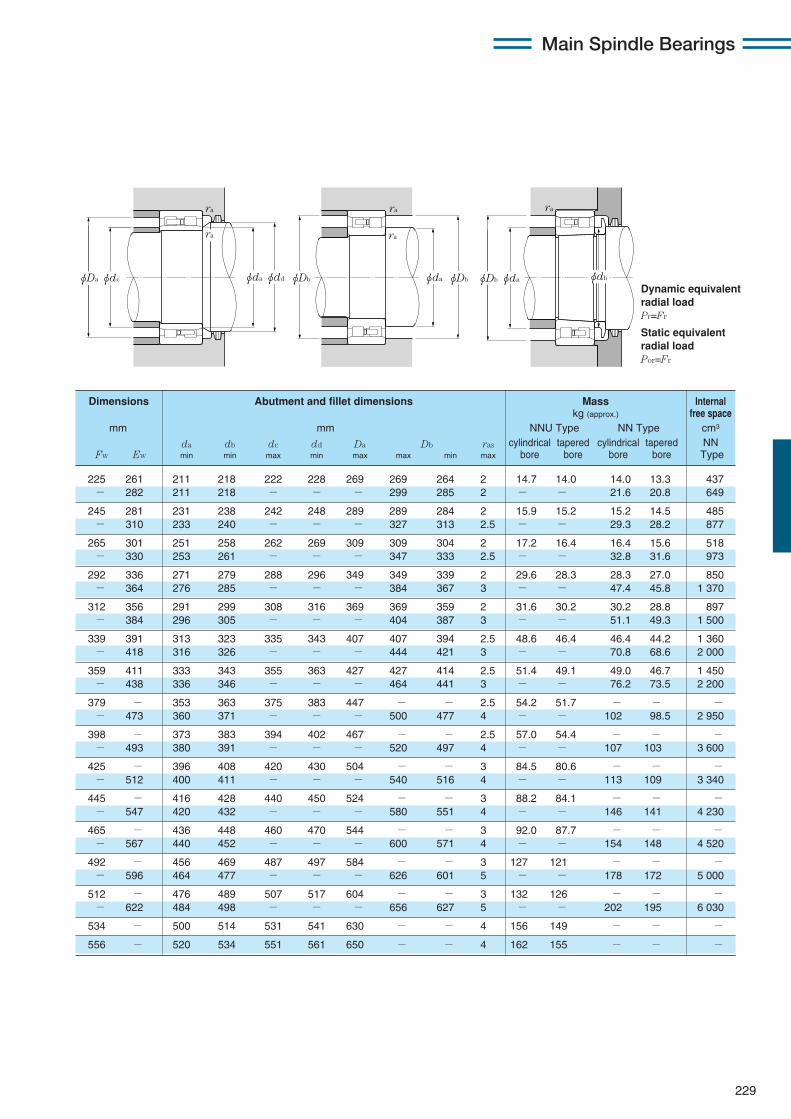
229
Main Spindle Bearings
Dynamic equivalentradial loadPr=Fr
Static equivalentradial loadPor=Fr
Dimensions Abutment and fillet dimensions Mass Internalkg (approx.) free space
mm mm NNU Type NN Type cm3
da db dc dd Da Db ras cylindrical tapered cylindrical tapered NNFw Ew min min max min max max min max bore bore bore bore Type
ra
ra ra
ra
ra
φdbφdaφDb φDb φdaφDbφdaφdc φddφDa
225 261 211 218 222 228 269 269 264 2 14.7 14.0 14.0 13.3 437− 282 211 218 − − − 299 285 2 − − 21.6 20.8 649
245 281 231 238 242 248 289 289 284 2 15.9 15.2 15.2 14.5 485− 310 233 240 − − − 327 313 2.5 − − 29.3 28.2 877
265 301 251 258 262 269 309 309 304 2 17.2 16.4 16.4 15.6 518− 330 253 261 − − − 347 333 2.5 − − 32.8 31.6 973
292 336 271 279 288 296 349 349 339 2 29.6 28.3 28.3 27.0 850− 364 276 285 − − − 384 367 3 − − 47.4 45.8 1 370
312 356 291 299 308 316 369 369 359 2 31.6 30.2 30.2 28.8 897− 384 296 305 − − − 404 387 3 − − 51.1 49.3 1 500
339 391 313 323 335 343 407 407 394 2.5 48.6 46.4 46.4 44.2 1 360− 418 316 326 − − − 444 421 3 − − 70.8 68.6 2 000
359 411 333 343 355 363 427 427 414 2.5 51.4 49.1 49.0 46.7 1 450− 438 336 346 − − − 464 441 3 − − 76.2 73.5 2 200
379 − 353 363 375 383 447 − − 2.5 54.2 51.7 − − −− 473 360 371 − − − 500 477 4 − − 102 98.5 2 950
398 − 373 383 394 402 467 − − 2.5 57.0 54.4 − − −− 493 380 391 − − − 520 497 4 − − 107 103 3 600
425 − 396 408 420 430 504 − − 3 84.5 80.6 − − −− 512 400 411 − − − 540 516 4 − − 113 109 3 340
445 − 416 428 440 450 524 − − 3 88.2 84.1 − − −− 547 420 432 − − − 580 551 4 − − 146 141 4 230
465 − 436 448 460 470 544 − − 3 92.0 87.7 − − −− 567 440 452 − − − 600 571 4 − − 154 148 4 520
492 − 456 469 487 497 584 − − 3 127 121 − − −− 596 464 477 − − − 626 601 5 − − 178 172 5 000
512 − 476 489 507 517 604 − − 3 132 126 − − −− 622 484 498 − − − 656 627 5 − − 202 195 6 030
534 − 500 514 531 541 630 − − 4 156 149 − − −
556 − 520 534 551 561 650 − − 4 162 155 − − −
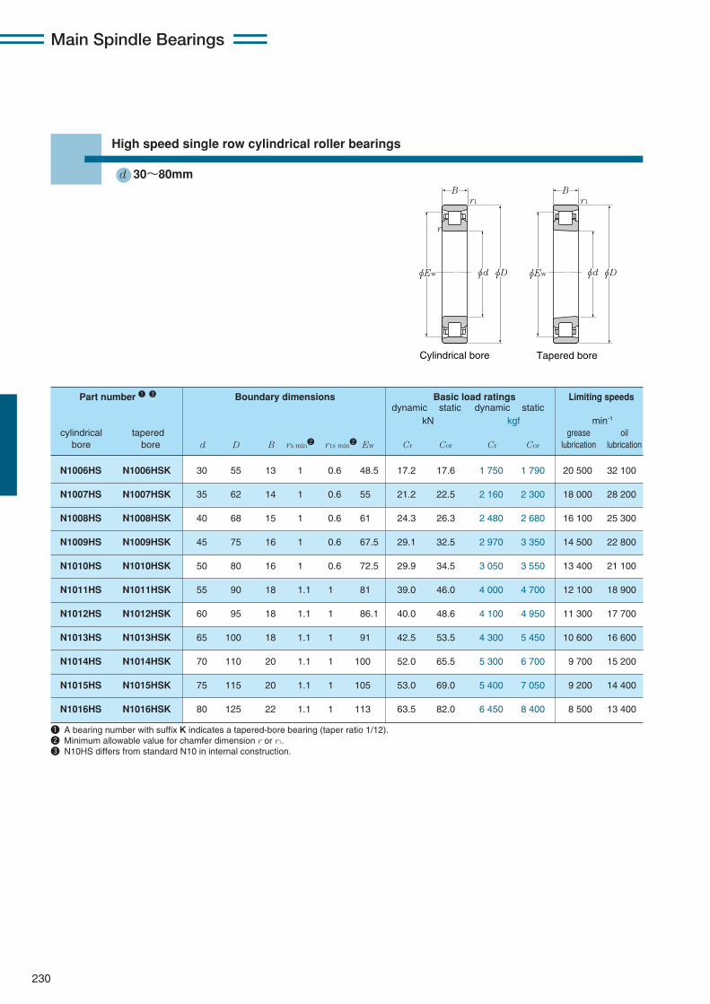
Main Spindle Bearings
230
High speed single row cylindrical roller bearings
d 30〜80mm
Tapered boreCylindrical bore
r
r1 r1
B B
φEw φEwφd φdφD φD
N1006HS N1006HSK 30 55 13 1 0.6 48.5 17.2 17.6 1 750 1 790 20 500 32 100
N1007HS N1007HSK 35 62 14 1 0.6 55 21.2 22.5 2 160 2 300 18 000 28 200
N1008HS N1008HSK 40 68 15 1 0.6 61 24.3 26.3 2 480 2 680 16 100 25 300
N1009HS N1009HSK 45 75 16 1 0.6 67.5 29.1 32.5 2 970 3 350 14 500 22 800
N1010HS N1010HSK 50 80 16 1 0.6 72.5 29.9 34.5 3 050 3 550 13 400 21 100
N1011HS N1011HSK 55 90 18 1.1 1 81 39.0 46.0 4 000 4 700 12 100 18 900
N1012HS N1012HSK 60 95 18 1.1 1 86.1 40.0 48.6 4 100 4 950 11 300 17 700
N1013HS N1013HSK 65 100 18 1.1 1 91 42.5 53.5 4 300 5 450 10 600 16 600
N1014HS N1014HSK 70 110 20 1.1 1 100 52.0 65.5 5 300 6 700 9 700 15 200
N1015HS N1015HSK 75 115 20 1.1 1 105 53.0 69.0 5 400 7 050 9 200 14 400
N1016HS N1016HSK 80 125 22 1.1 1 113 63.5 82.0 6 450 8 400 8 500 13 400
Part number 1 3 Boundary dimensions Basic load ratings Limiting speedsdynamic static dynamic static
kN kgf min-1
cylindrical tapered grease oilbore bore d D B rs min2 r1s min2 Ew Cr Cor Cr Cor lubrication lubrication
1 A bearing number with suffix K indicates a tapered-bore bearing (taper ratio 1/12).2 Minimum allowable value for chamfer dimension r or r1.3 N10HS differs from standard N10 in internal construction.

231
Main Spindle Bearings
Dynamic equivalentradial loadPr=Fr
Static equivalentradial loadPor=Fr
35 50 49 1 0.6 0.143 4.33 N1006HS N1006HSK
40 57 56 1 0.6 0.190 5.06 N1007HS N1007HSK
45 63 62 1 0.6 0.235 7.10 N1008HS N1008HSK
50 70 69 1 0.6 0.298 8.85 N1009HS N1009HSK
55 75 74 1 0.6 0.323 10.8 N1010HS N1010HSK
61.5 83.5 82 1 1 0.473 15.0 N1011HS N1011HSK
66.5 88.5 87 1 1 0.505 15.3 N1012HS N1012HSK
71.5 93.5 92 1 1 0.538 19.0 N1013HS N1013HSK
76.5 103.5 101 1 1 0.745 22.0 N1014HS N1014HSK
81.5 108.5 106 1 1 0.787 26.5 N1015HS N1015HSK
86.5 118.5 114 1 1 1.05 31.1 N1016HS N1016HSK
Abutment and Mass Internal Part number fillet dimensions cylindrical free space
mm bore cm3
da Db ras r1as kg cylindrical taperedmin max min max max (approx.) bore bore
φDb φdaφDb
r1a
ra
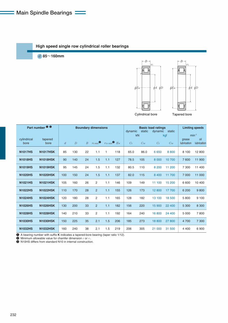
Main Spindle Bearings
232
High speed single row cylindrical roller bearings
d 85〜160mm
1 A bearing number with suffix K indicates a tapered-bore bearing (taper ratio 1/12).2 Minimum allowable value for chamfer dimension r or r1.3 N10HS differs from standard N10 in internal construction.
Tapered boreCylindrical bore
r
r1 r1
B B
φEw φEwφd φdφD φD
N1017HS N1017HSK 85 130 22 1.1 1 118 65.0 86.0 6 650 8 800 8 100 12 800
N1018HS N1018HSK 90 140 24 1.5 1.1 127 78.5 105 8 000 10 700 7 600 11 900
N1019HS N1019HSK 95 145 24 1.5 1.1 132 80.5 110 8 200 11 200 7 300 11 400
N1020HS N1020HSK 100 150 24 1.5 1.1 137 82.0 115 8 400 11 700 7 000 11 000
N1021HS N1021HSK 105 160 26 2 1.1 146 109 149 11 100 15 200 6 600 10 400
N1022HS N1022HSK 110 170 28 2 1.1 155 126 173 12 800 17 700 6 200 9 800
N1024HS N1024HSK 120 180 28 2 1.1 165 128 182 13 100 18 500 5 800 9 100
N1026HS N1026HSK 130 200 33 2 1.1 182 156 220 15 900 22 400 5 300 8 300
N1028HS N1028HSK 140 210 33 2 1.1 192 164 240 16 800 24 400 5 000 7 800
N1030HS N1030HSK 150 225 35 2.1 1.5 206 185 273 18 800 27 800 4 700 7 300
N1032HS N1032HSK 160 240 38 2.1 1.5 219 206 305 21 000 31 500 4 400 6 900
Part number 1 3 Boundary dimensions Basic load ratings Limiting speedsdynamic static dynamic static
kN kgf min-1
cylindrical tapered grease oilbore bore d D B rs min2 r1s min2 Ew Cr Cor Cr Cor lubrication lubrication
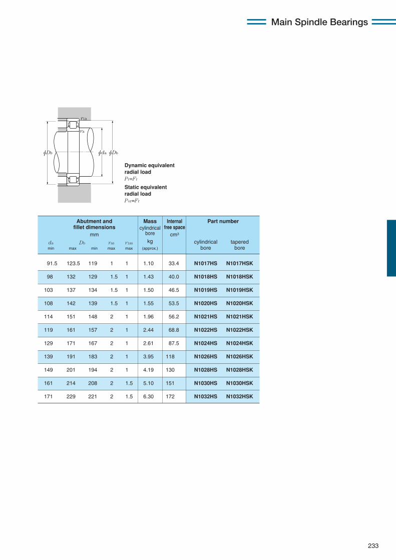
233
Main Spindle Bearings
Dynamic equivalentradial loadPr=Fr
Static equivalentradial loadPor=Fr
φDb φdaφDb
r1a
ra
91.5 123.5 119 1 1 1.10 33.4 N1017HS N1017HSK
98 132 129 1.5 1 1.43 40.0 N1018HS N1018HSK
103 137 134 1.5 1 1.50 46.5 N1019HS N1019HSK
108 142 139 1.5 1 1.55 53.5 N1020HS N1020HSK
114 151 148 2 1 1.96 56.2 N1021HS N1021HSK
119 161 157 2 1 2.44 68.8 N1022HS N1022HSK
129 171 167 2 1 2.61 87.5 N1024HS N1024HSK
139 191 183 2 1 3.95 118 N1026HS N1026HSK
149 201 194 2 1 4.19 130 N1028HS N1028HSK
161 214 208 2 1.5 5.10 151 N1030HS N1030HSK
171 229 221 2 1.5 6.30 172 N1032HS N1032HSK
Abutment and Mass Internal Part number fillet dimensions cylindrical free space
mm bore cm3
da Db ras r1as kg cylindrical taperedmin max min max max (approx.) bore bore
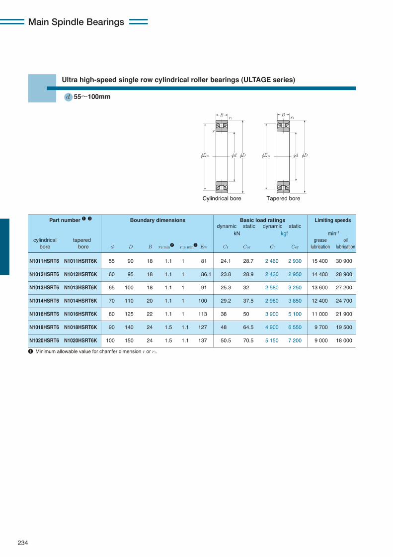
Main Spindle Bearings
234
Ultra high-speed single row cylindrical roller bearings (ULTAGE series)
d 55〜100mm
Tapered boreCylindrical bore
r1
φEw φd φD
Br1
r
φEw φd φD
B
1 Minimum allowable value for chamfer dimension r or r1.
N1011HSRT6 N1011HSRT6K 55 90 18 1.1 1 81 24.1 28.7 2 460 2 930 15 400 30 900
N1012HSRT6 N1012HSRT6K 60 95 18 1.1 1 86.1 23.8 28.9 2 430 2 950 14 400 28 900
N1013HSRT6 N1013HSRT6K 65 100 18 1.1 1 91 25.3 32 2 580 3 250 13 600 27 200
N1014HSRT6 N1014HSRT6K 70 110 20 1.1 1 100 29.2 37.5 2 980 3 850 12 400 24 700
N1016HSRT6 N1016HSRT6K 80 125 22 1.1 1 113 38 50 3 900 5 100 11 000 21 900
N1018HSRT6 N1018HSRT6K 90 140 24 1.5 1.1 127 48 64.5 4 900 6 550 9 700 19 500
N1020HSRT6 N1020HSRT6K 100 150 24 1.5 1.1 137 50.5 70.5 5 150 7 200 9 000 18 000
Part number 1 3 Boundary dimensions Basic load ratings Limiting speedsdynamic static dynamic static
kN kgf min-1
cylindrical tapered grease oilbore bore d D B rs min2 r1s min2 Ew Cr Cor Cr Cor lubrication lubrication
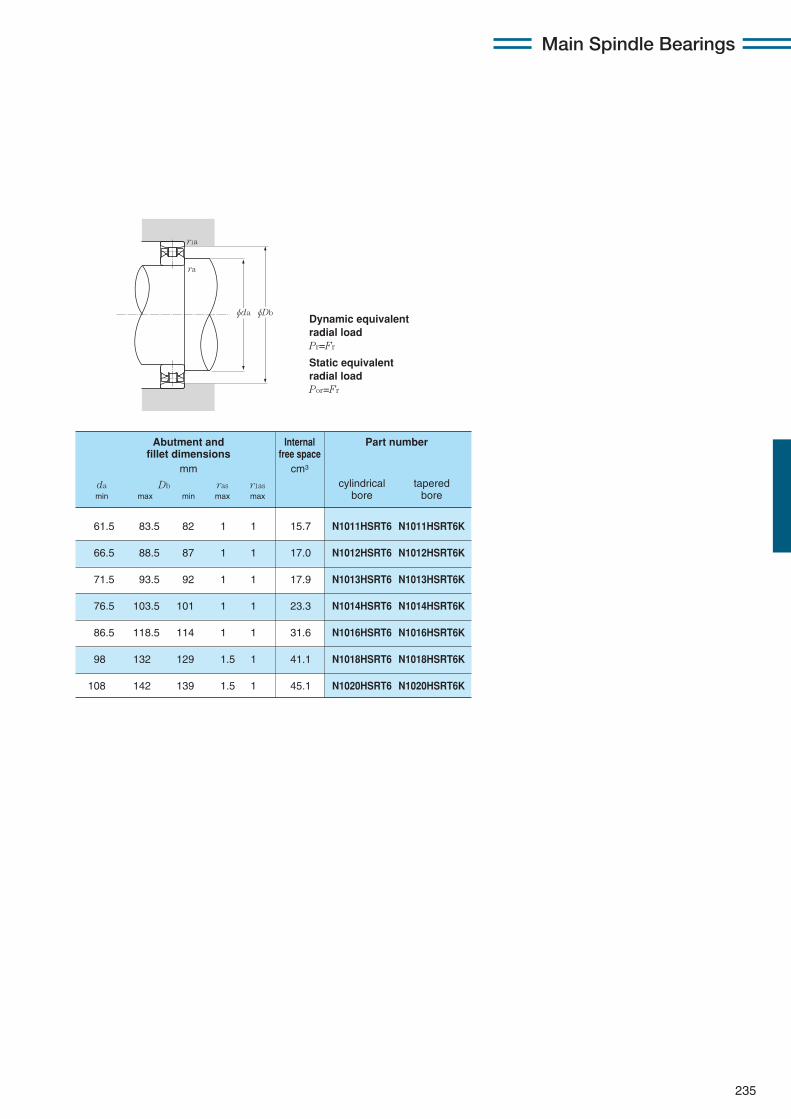
235
Main Spindle Bearings
Dynamic equivalentradial loadPr=Fr
Static equivalentradial loadPor=Fr
61.5 83.5 82 1 1 15.7 N1011HSRT6 N1011HSRT6K
66.5 88.5 87 1 1 17.0 N1012HSRT6 N1012HSRT6K
71.5 93.5 92 1 1 17.9 N1013HSRT6 N1013HSRT6K
76.5 103.5 101 1 1 23.3 N1014HSRT6 N1014HSRT6K
86.5 118.5 114 1 1 31.6 N1016HSRT6 N1016HSRT6K
98 132 129 1.5 1 41.1 N1018HSRT6 N1018HSRT6K
108 142 139 1.5 1 45.1 N1020HSRT6 N1020HSRT6K
Abutment and Internal Part number fillet dimensions free space
mm cm3
da Db ras r1as cylindrical taperedmin max min max max bore bore
ra
r1a
φDbφda
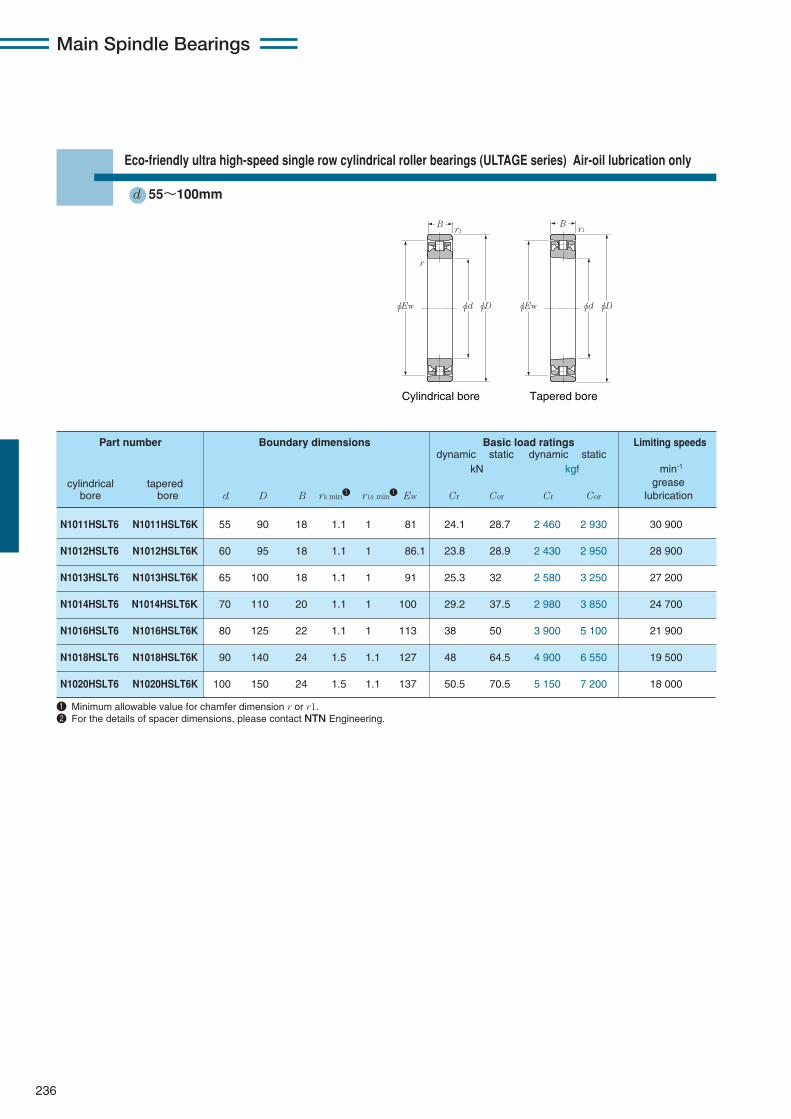
Main Spindle Bearings
236
Eco-friendly ultra high-speed single row cylindrical roller bearings (ULTAGE series) Air-oil lubrication only
d 55〜100mm
Tapered boreCylindrical bore
r1
φEw φd φD
B
r
r1
φEw φd φD
B
1 Minimum allowable value for chamfer dimension r or r1.2 For the details of spacer dimensions, please contact NTN Engineering.
N1011HSLT6 N1011HSLT6K 55 90 18 1.1 1 81 24.1 28.7 2 460 2 930 30 900
N1012HSLT6 N1012HSLT6K 60 95 18 1.1 1 86.1 23.8 28.9 2 430 2 950 28 900
N1013HSLT6 N1013HSLT6K 65 100 18 1.1 1 91 25.3 32 2 580 3 250 27 200
N1014HSLT6 N1014HSLT6K 70 110 20 1.1 1 100 29.2 37.5 2 980 3 850 24 700
N1016HSLT6 N1016HSLT6K 80 125 22 1.1 1 113 38 50 3 900 5 100 21 900
N1018HSLT6 N1018HSLT6K 90 140 24 1.5 1.1 127 48 64.5 4 900 6 550 19 500
N1020HSLT6 N1020HSLT6K 100 150 24 1.5 1.1 137 50.5 70.5 5 150 7 200 18 000
Part number Boundary dimensions Basic load ratings Limiting speedsdynamic static dynamic static
kN kgf min-1
cylindrical tapered greasebore bore d D B rs min1 r1s min1 Ew Cr Cor Cr Cor lubrication
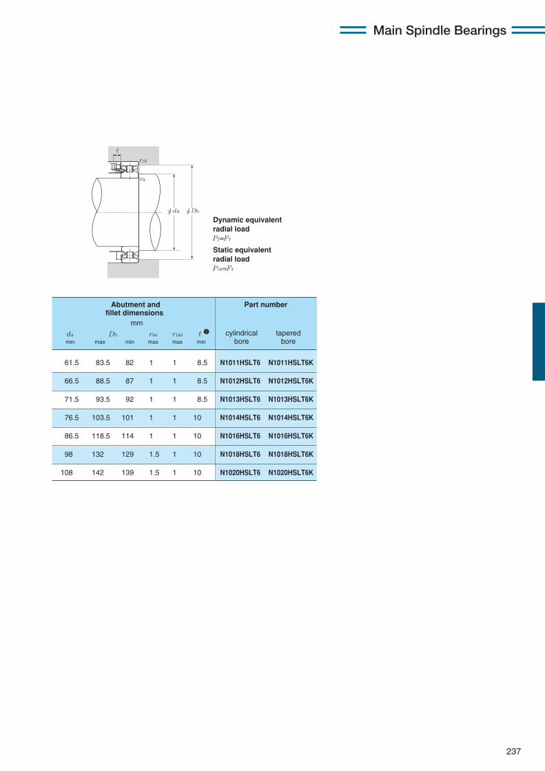
237
Main Spindle Bearings
Dynamic equivalentradial loadPr=Fr
Static equivalentradial loadPor=Fr
61.5 83.5 82 1 1 8.5 N1011HSLT6 N1011HSLT6K
66.5 88.5 87 1 1 8.5 N1012HSLT6 N1012HSLT6K
71.5 93.5 92 1 1 8.5 N1013HSLT6 N1013HSLT6K
76.5 103.5 101 1 1 10 N1014HSLT6 N1014HSLT6K
86.5 118.5 114 1 1 10 N1016HSLT6 N1016HSLT6K
98 132 129 1.5 1 10 N1018HSLT6 N1018HSLT6K
108 142 139 1.5 1 10 N1020HSLT6 N1020HSLT6K
Abutment and Part number fillet dimensions
mm
da Db ras r1as r2 cylindrical taperedmin max min max max min bore bore
ra
r1a
φDbφda
r
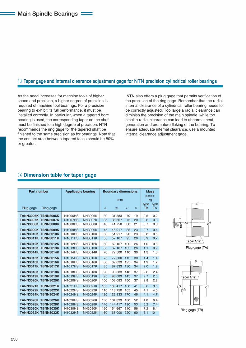
Main Spindle Bearings
238
!3 Taper gage and internal clearance adjustment gage for NTN precision cylindrical roller bearings
!4 Dimension table for taper gage
TANN3006K TBNN3006K N1006HS NN3006K 30 31.583 70 19 0.5 0.2TANN3007K TBNN3007K N1007HS NN3007K 35 36.667 75 20 0.6 0.3TANN3008K TBNN3008K N1008HS NN3008K 40 41.750 80 21 0.7 0.3
TANN3009K TBNN3009K N1009HS NN3009K 45 46.917 85 23 0.7 0.4TANN3010K TBNN3010K N1010HS NN3010K 50 51.917 90 23 0.8 0.5TANN3011K TBNN3011K N1011HS NN3011K 55 57.167 95 26 0.9 0.7
TANN3012K TBNN3012K N1012HS NN3012K 60 62.167 100 26 1.0 0.8TANN3013K TBNN3013K N1013HS NN3013K 65 67.167 105 26 1.1 0.9TANN3014K TBNN3014K N1014HS NN3014K 70 72.500 110 30 1.3 1.3
TANN3015K TBNN3015K N1015HS NN3015K 75 77.500 115 30 1.4 1.4TANN3016K TBNN3016K N1016HS NN3016K 80 82.833 125 34 1.9 1.7TANN3017K TBNN3017K N1017HS NN3017K 85 87.833 130 34 2.0 1.9
TANN3018K TBNN3018K N1018HS NN3018K 90 93.083 140 37 2.6 2.4TANN3019K TBNN3019K N1019HS NN3019K 95 98.083 145 37 2.7 2.6TANN3020K TBNN3020K N1020HS NN3020K 100 103.083 150 37 2.8 2.8
TANN3021K TBNN3021K N1021HS NN3021K 105 108.417 160 41 3.6 3.5TANN3022K TBNN3022K N1022HS NN3022K 110 113.750 165 45 4.1 4.0TANN3024K TBNN3024K N1024HS NN3024K 120 123.833 170 46 4.1 4.7
TANN3026K TBNN3026K N1026HS NN3026K 130 134.333 180 52 4.8 6.4TANN3028K TBNN3028K N1028HS NN3028K 140 144.417 190 53 5.2 7.4TANN3030K TBNN3030K N1030HS NN3030K 150 154.667 210 56 7.2 8.4TANN3032K TBNN3032K N1032HS NN3032K 160 165.000 220 60 8.1 10
Part number Applicable bearing Boundary dimensions Mass(approx.)
mm kgtype type
Plug gage Ring gage d d1 D B TB TA
φd
φdφD
φd1
φd1
B
B
Ring gage (TB)
Taper 1/12
Plug gage (TA)
Taper 1/12
As the need increases for machine tools of higherspeed and precision, a higher degree of precision isrequired of machine tool bearings. For a precisionbearing to exhibit its full performance, it must beinstalled correctly. In particular, when a tapered borebearing is used, the corresponding taper on the shaftmust be finished to a high degree of precision. NTNrecommends the ring gage for the tapered shaft befinished to the same precision as for bearings. Note thatthe contact area between tapered faces should be 80%or greater.
NTN also offers a plug gage that permits verification ofthe precision of the ring gage. Remember that the radialinternal clearance of a cylindrical roller bearing needs tobe correctly adjusted. Too large a radial clearance candiminish the precision of the main spindle, while toosmall a radial clearance can lead to abnormal heatgeneration and premature flaking of the bearing. Toensure adequate internal clearance, use a mountedinternal clearance adjustment gage.
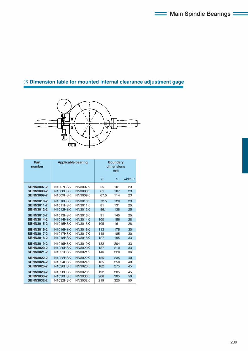
239
Main Spindle Bearings
!5 Dimension table for mounted internal clearance adjustment gage
SBNN3007-2 N1007HSK NN3007K 55 101 23SBNN3008-2 N1008HSK NN3008K 61 107 23SBNN3009-2 N1009HSK NN3009K 67.5 114 23
SBNN3010-2 N1010HSK NN3010K 72.5 120 23SBNN3011-2 N1011HSK NN3011K 81 131 25SBNN3012-2 N1012HSK NN3012K 86.1 138 25
SBNN3013-2 N1013HSK NN3013K 91 145 25SBNN3014-2 N1014HSK NN3014K 100 156 28SBNN3015-2 N1015HSK NN3015K 105 161 28
SBNN3016-2 N1016HSK NN3016K 113 175 30SBNN3017-2 N1017HSK NN3017K 118 185 30SBNN3018-2 N1018HSK NN3018K 127 195 33
SBNN3019-2 N1019HSK NN3019K 132 204 33SBNN3020-2 N1020HSK NN3020K 137 210 33SBNN3021-2 N1021HSK NN3021K 146 220 36
SBNN3022-2 N1022HSK NN3022K 155 235 40SBNN3024-2 N1024HSK NN3024K 165 250 40SBNN3026-2 N1026HSK NN3026K 182 275 45
SBNN3028-2 N1028HSK NN3028K 192 285 45SBNN3030-2 N1030HSK NN3030K 206 305 50SBNN3032-2 N1032HSK NN3032K 219 320 50
Part Applicable bearing Boundarynumber dimensions
mm
E D width B
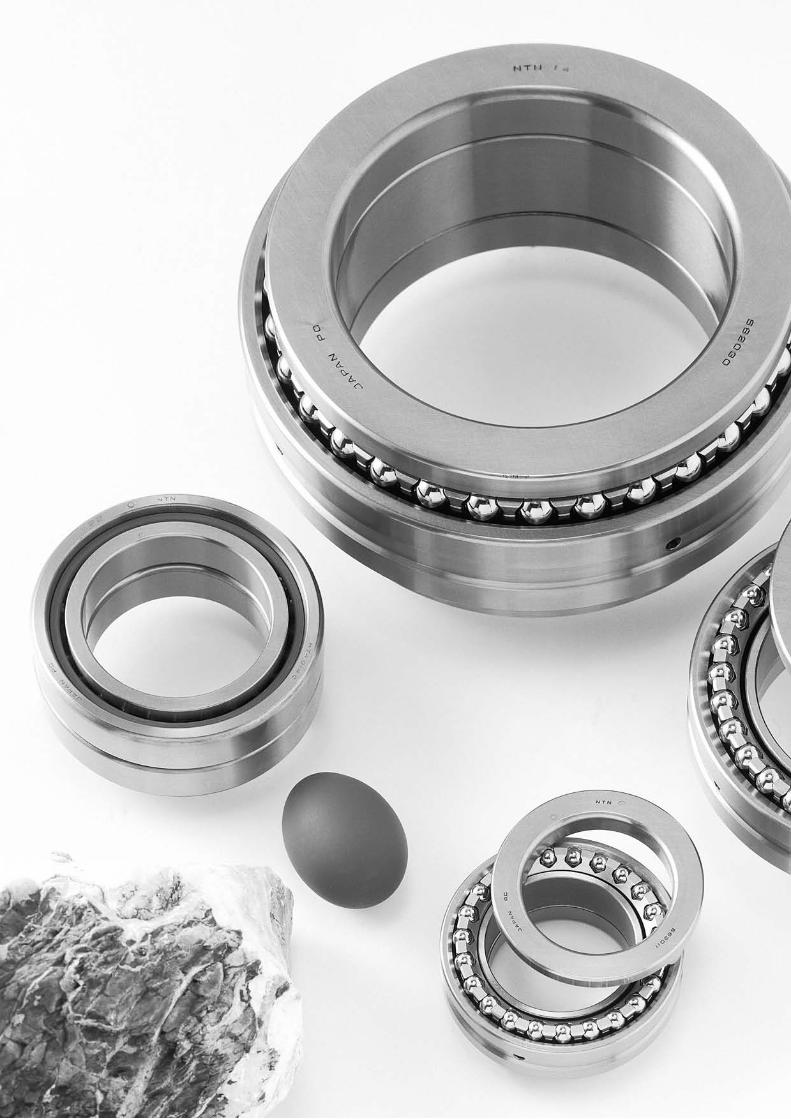
NTN Main Spindle Bearings

NTN Main Spindle Bearings
241
Main Spindle Bearings
11. Angular Contact Ball Bearings for Axial Loads CONTENTS
11. Angular Contact Ball Bearings for Axial Loads …………………………242〜265q Features and types …………………………………………………………………242
w Standard cage types ………………………………………………………………243
e Bearing designations………………………………………………………………243
r Accuracy of double-direction angular contact thrust ball bearings ……244
t Accuracy of high-speed duplex angular contact ball bearings for axial loads ……245
y Basic preload…………………………………………………………………………246
u Shaft and housing fits ……………………………………………………………247
i Recommended lubrication specifications ……………………………………247
o Angular contact ball bearings for axial loads HTA U type…………………248
!0 Dimension tables
Double-direction angular contact thrust ball bearings …………………250
Angular contact ball bearings for axial loads ……………………………254
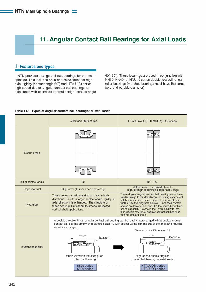
NTN Main Spindle Bearings
242
11. Angular Contact Ball Bearings for Axial Loads
NTN provides a range of thrust bearings for the mainspindles. This includes 5629 and 5620 series for highaxial rigidity (contact angle 60˚) and HTA U(A) serieshigh-speed duplex angular contact ball bearings foraxial loads with optimized internal design (contact angle
① Features and types
A 2BSpacer C Spacer D
5629 and 5620 series HTA0U (A)..DB, HTA9U (A)..DB series
Bearing type
Initial contact angle 60° 40°,30°
Cage material
Features
Interchangeability
Molded resin, machined phenolic, high-strength machined copper alloy cage
High-strength machined brass cage
A double-direction thrust angular contact ball bearing can be readily interchanged with a duplex angular contact ball bearing simply by replacing spacer C with spacer D; the dimensions of the shaft and housing remain unchanged.
5629 series 5620 series
HTA9UDB series HTB0UDB series
Double-direction thrust angular contact ball bearing
High-speed duplex angular contact ball bearing for axial loads
Dimension A = Dimension 2B
These series can withstand axial loads in both directions. Due to a larger contact angle, rigidity in axial directions is enhanced. The structure of these bearings limits them to grease-lubricated vertical shaft applications.
These duplex angular contact ball bearing series have similar design to the double-row thrust angular contact ball bearing series, but are different in terms of their widths (see the diagrams below). Since their contact angles are lower at 40° and 30°, the series boast high-speed capability. However, their axial rigidity is less than double-row thrust angular contact ball bearings with 60° contact angle.
Table 11.1 Types of angular contact ball bearings for axial loads
40˚, 30˚). These bearings are used in conjunction withNN30, NN49, or NNU49 series double-row cylindricalroller bearings (matched bearings must have the samebore and outside diameter).
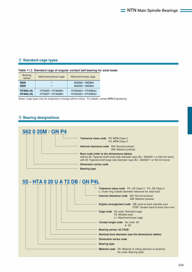
NTN Main Spindle Bearings
243
② Standard cage types
③ Bearing designations
Bearing series Machined phenol cage Machined brass cage
5629 5620
HTA9U (A) HTA0U (A)
- -
HTA920~HTA938U HTA007~HTA038U
562920~562964 562005~562064
HTA940U~HTA964U HTA040U~HTA064U
Notes: Cage types may be subjected to change without notice. For details, contact NTN Engineering.
Table 11.2 Standard cage of angular contact ball bearing for axial loads
Internal clearance code GN: Normal preload GM: Medium preload
Bore code (refer to the dimensions tables) without M: Tapered shaft small side diameter type (Ex.: 562020→φ100 mm bore) with M: Tapered shaft large side diameter type (Ex.: 562020→φ103 mm bore)
Bearing type
Dimension series code
Tolerance class code P5: NTN Class 5 P4: NTN Class 4
562 0 20M / GN P4
Tolerance class code P5: JIS Class 5 P4: JIS Class 4 L: Outer ring outside diameter tolerance for axial load Internal clearance code GN: Normal preload GM: Medium preload
Duplex arrangement code DB: back-to-back (double-row) DTBT: tandem back-to-back (four-row) Cage code No code: Standard cage T2: Molded resin L1: Machined brass cage Contact angle code No code: 40˚ A: 30˚
Nominal bore diameter (see the dimensions tables)
Bearing series: ULTAGE
Dimension series code
Bearing type
Material code 5S: Material of rolling element is ceramics No code: Bearing steel
5S - HTA 0 20 U A T2 DB / GN P4L
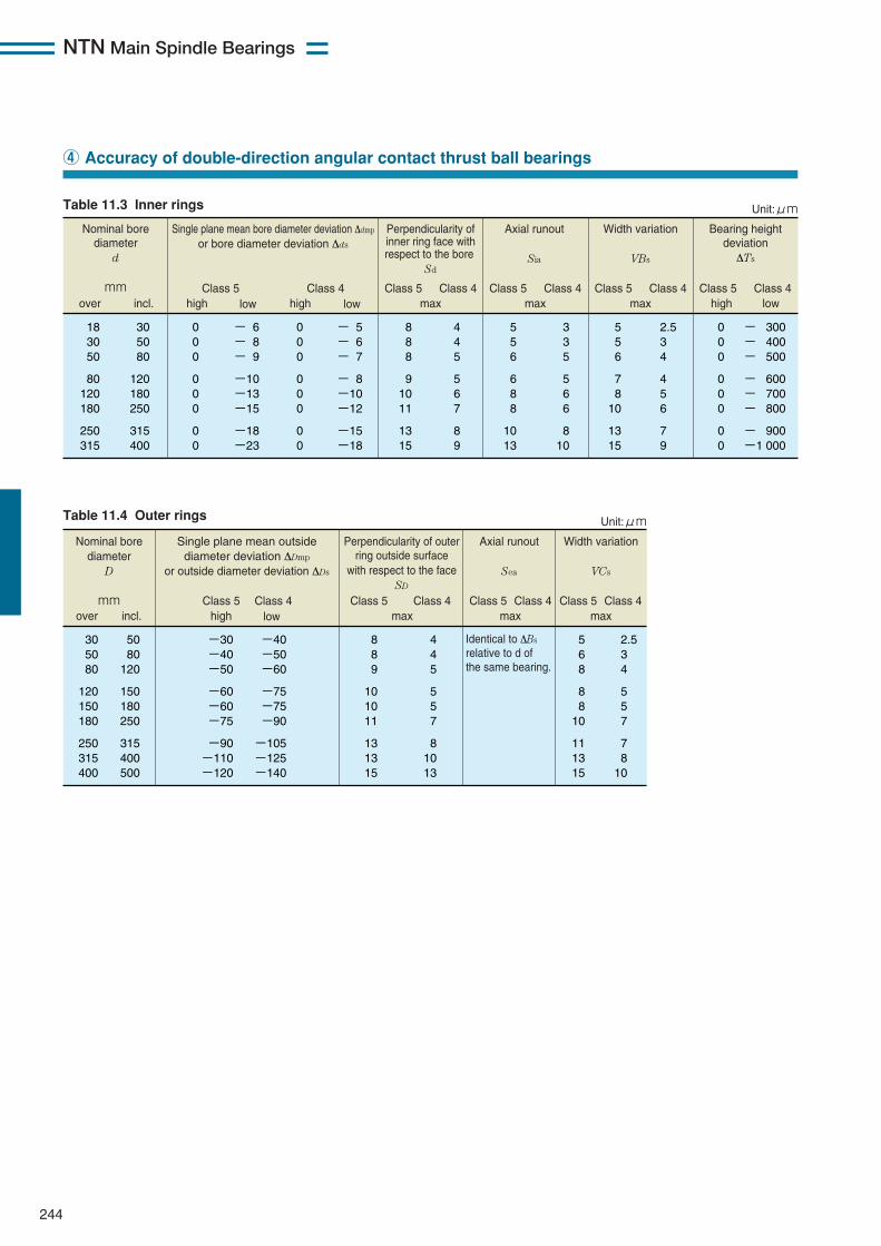
NTN Main Spindle Bearings
244
④ Accuracy of double-direction angular contact thrust ball bearings
Nominal bore diameter
d mm
Single plane mean bore diameter deviation Δdmp or bore diameter deviation Δds
Class 5 Class 4
18 30 50
80 120 180
250 315
30 50 80
120 180 250
315 400
2.5 3 4
4 5 6
7 9
5 5 6
7 8
10
13 15
3 3 5
5 6 6
8 10
5 5 6
6 8 8
10 13
4 4 5
5 6 7
8 9
8 8 8
9 10 11
13 15
0 0 0
0 0 0
0 0
- 300 - 400 - 500
- 600 - 700 - 800
- 900 -1 000
0 0 0
0 0 0
0 0
0 0 0
0 0 0
0 0
- 5 - 6 - 7
- 8 -10 -12
-15 -18
- 6 - 8 - 9
-10 -13 -15
-18 -23
over incl.
Axial runout
Sia
high lowhigh lowClass 5 Class 4
maxClass 5 Class 4
maxClass 5 Class 4 Class 5 Class 4
max
Perpendicularity of inner ring face with respect to the bore
Sd
Unit:μm
Width variation
VBs
Bearing height deviation ΔTs
high low
Table 11.3 Inner rings
Table 11.4 Outer rings
Nominal bore diameter
D mm
Single plane mean outside diameter deviation ΔDmp
or outside diameter deviation ΔDs
Class 5 Class 4
30 50 80
120 150 180
250 315 400
50 80
120
150 180 250
315 400 500
8 8 9
10 10 11
13 13 15
4 4 5
5 5 7
8 10 13
Identical to ΔBs relative to d of the same bearing.
5 6 8
8 8
10
11 13 15
2.5 3 4
5 5 7
7 8 10
-30 -40 -50
-60 -60 -75
-90 -110 -120
-40 -50 -60
-75 -75 -90
-105 -125 -140
over incl.
Perpendicularity of outer ring outside surface
with respect to the face SD
high lowClass 5 Class 4
max
Axial runout
Sea
Class 5 Class 4max
Unit:μm
Width variation
VCs
Class 5 Class 4max
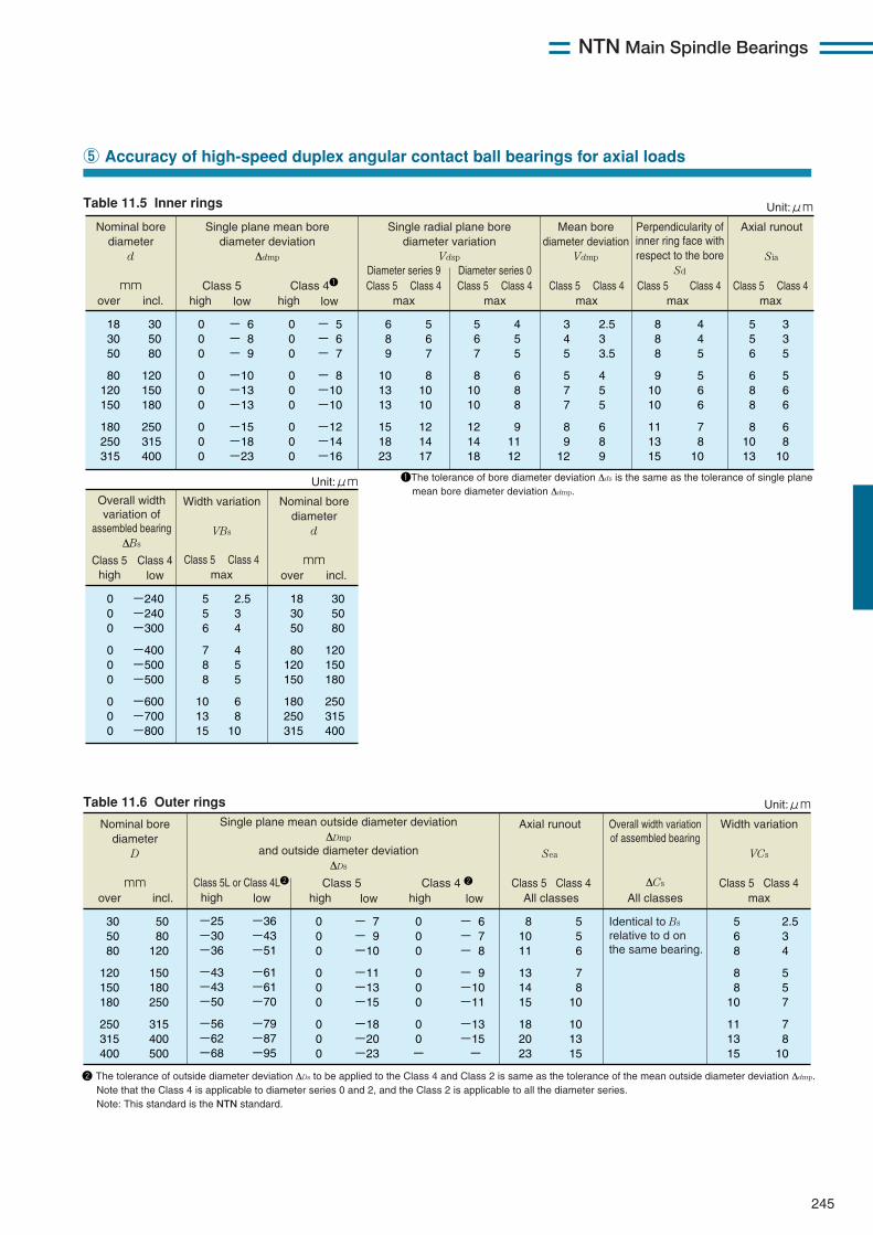
NTN Main Spindle Bearings
245
Nominal bore diameter
D mm Class 5
30 50 80
120 150 180
250 315 400
50 80
120
150 180 250
315 400 500
2.5 3 4
5 5 7
7 8 10
5 6 8
8 8
10
11 13 15
Identical to Bs relative to d on the same bearing.
5 5 6
7 8
10
10 13 15
8 10 11
13 14 15
18 20 23
0 0 0
0 0 0
0 0 0
- 7 - 9 -10
-11 -13 -15
-18 -20 -23
over incl.
Axial runout
Sea
high lowClass 4 2
0 0 0
0 0 0
0 0 -
- 6 - 7 - 8
- 9 -10 -11
-13 -15 -
high lowClass 5 Class 4
All classes
Unit:μm
Width variation
VCs
Class 5 Class 4max
Overall width variation of assembled bearing
ΔCs
All classes
Single plane mean outside diameter deviation ΔDmp
and outside diameter deviation ΔDs
Class 5L or Class 4L2
-25 -30 -36
-43 -43 -50
-56 -62 -68
-36 -43 -51
-61 -61 -70
-79 -87 -95
high low
2 The tolerance of outside diameter deviation ΔDs to be applied to the Class 4 and Class 2 is same as the tolerance of the mean outside diameter deviation Δdmp. Note that the Class 4 is applicable to diameter series 0 and 2, and the Class 2 is applicable to all the diameter series. Note: This standard is the NTN standard.
Table 11.6 Outer rings
⑤ Accuracy of high-speed duplex angular contact ball bearings for axial loads
Nominal bore diameter
d mm
Single plane mean bore diameter deviation
Δdmp
Class 5 Class 41
Single radial plane bore diameter variation
Vdsp
Diameter series 9
18 30 50
80 120 150
180 250 315
30 50 80
120 150 180
250 315 400
6 8 9
10 13 13
15 18 23
5 6 7
8 10 10
12 14 17
5 6 7
8 10 10
12 14 18
4 5 5
6 8 8
9 11 12
3 4 5
5 7 7
8 9
12
2.5 3 3.5
4 5 5
6 8 9
8 8 8
9 10 10
11 13 15
4 4 5
5 6 6
7 8
10
5 5 6
6 8 8
8 10 13
3 3 5
5 6 6
6 8
10
0 0 0
0 0 0
0 0 0
- 6 - 8 - 9
-10 -13 -13
-15 -18 -23
0 0 0
0 0 0
0 0 0
- 5 - 6 - 7
- 8 -10 -10
-12 -14 -16
over incl.
high low
Axial runout
Sia
high lowhigh low
Diameter series 0
Mean bore diameter deviation
Vdmp
Class 5 Class 4max
Class 5 Class 4max
Class 5 Class 4max
Class 5 Class 4max
Class 5 Class 4max
Class 5 Class 4max
Perpendicularity of inner ring face with respect to the bore
Sd
Unit:μm
Nominal bore diameter
d mm
18 30 50
80 120 150
180 250 315
30 50 80
120 150 180
250 315 400
over incl.
Unit:μm
Width variation
VBs
0 0 0
0 0 0
0 0 0
2.5 3 4
4 5 5
6 8 10
5 5 6
7 8 8
10 13 15
-240 -240 -300
-400 -500 -500
-600 -700 -800
Class 5 Class 4
Overall width variation of
assembled bearing ΔBs
1The tolerance of bore diameter deviation Δds is the same as the tolerance of single plane mean bore diameter deviation Δdmp.
Table 11.5 Inner rings
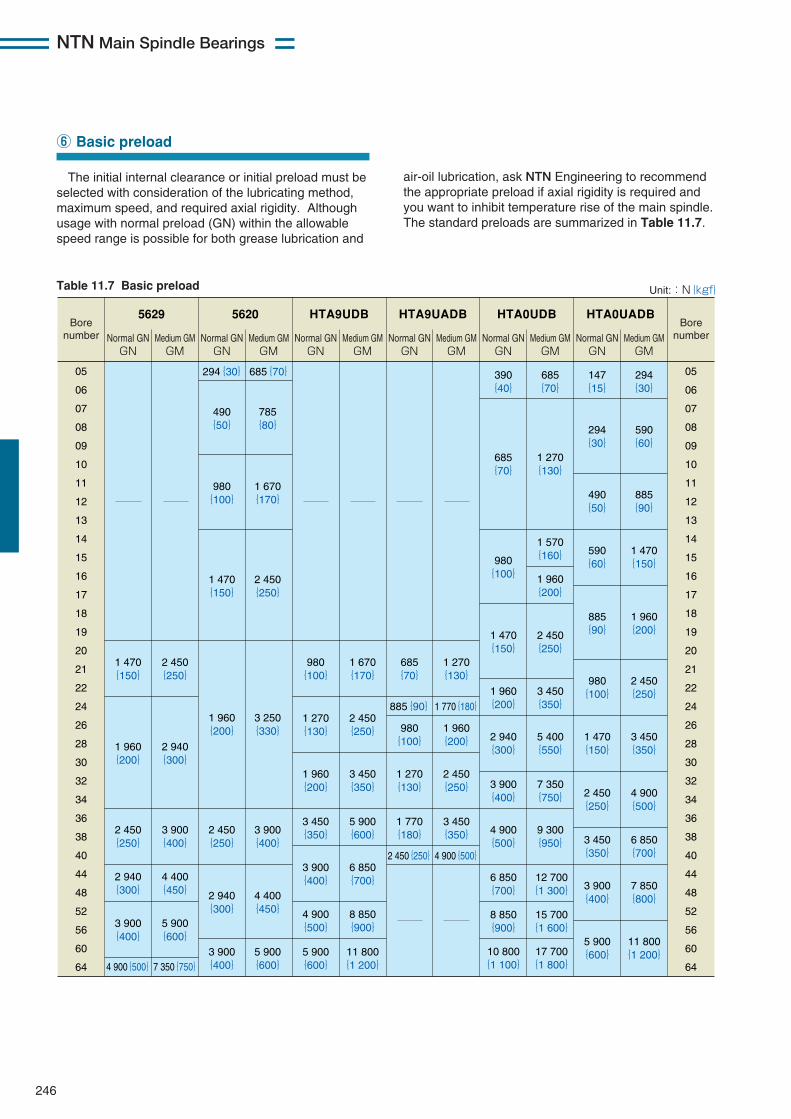
NTN Main Spindle Bearings
246
The initial internal clearance or initial preload must beselected with consideration of the lubricating method,maximum speed, and required axial rigidity. Althoughusage with normal preload (GN) within the allowablespeed range is possible for both grease lubrication and
⑥ Basic preload
Bore number
Bore number
5629
Normal GN GN
Medium GM GM
Normal GN GN
Medium GM GM
Normal GN GN
Medium GM GM
Normal GN GN
Medium GM GM
Normal GN GN
Medium GM GM
Normal GN GN
Medium GM GM
5620 HTA9UDB HTA9UADB HTA0UDB HTA0UADB
05
06
07
08
09
10
11
12
13
14
15
16
17
18
19
20
21
22
24
26
28
30
32
34
36
38
40
44
48
52
56
60
64
05
06
07
08
09
10
11
12
13
14
15
16
17
18
19
20
21
22
24
26
28
30
32
34
36
38
40
44
48
52
56
60
64
390 {40}
685 {70}
1 270 {130}
980 {100}
1 960 {200}
1 270 {130}
2 450 {250}
1 770 {180}
3 450 {350}
885{90} 1 770{180}
2 450{250} 4 900{500}
685 {70}
147 {15}
294 {30}
294{30} 685{70}
785 {80}
490 {50} 294
{30} 590 {60}
980 {100}
1 670 {170}
685 {70}
1 270 {130}
490 {50}
885 {90}
1 570 {160} 590
{60} 1 470 {150} 980
{100} 1 960 {200}
1 470 {150}
2 450 {250}
1 470 {150}
2 450 {250}
1 960 {200}
2 940 {300}
2 450 {250}
3 900 {400}
2 940 {300}
4 400 {450}
3 900 {400}
5 900 {600}
4 900{500} 7 350{750}
1 960 {200}
3 250 {330}
2 450 {250}
3 900 {400}
2 940 {300}
4 400 {450}
3 900 {400}
5 900 {600}
980 {100}
1 670 {170}
1 270 {130}
2 450 {250}
1 960 {200}
3 450 {350}
3 450 {350}
5 900 {600}
3 900 {400}
6 850 {700}
4 900 {500}
8 850 {900}
5 900 {600}
11 800 {1 200}
1 470 {150}
2 450 {250}
1 960 {200}
3 450 {350}
2 940 {300}
5 400 {550}
3 900 {400}
7 350 {750}
4 900 {500}
9 300 {950}
6 850 {700}
12 700 {1 300}
8 850 {900}
10 800 {1 100}
15 700 {1 600}
17 700 {1 800}
885 {90}
1 960 {200}
980 {100}
2 450 {250}
1 470 {150}
3 450 {350}
2 450 {250}
4 900 {500}
3 450 {350}
6 850 {700}
3 900 {400}
7 850 {800}
5 900 {600}
11 800 {1 200}
Unit::N{kgf} Table 11.7 Basic preload
air-oil lubrication, ask NTN Engineering to recommendthe appropriate preload if axial rigidity is required andyou want to inhibit temperature rise of the main spindle.The standard preloads are summarized in Table 11.7.
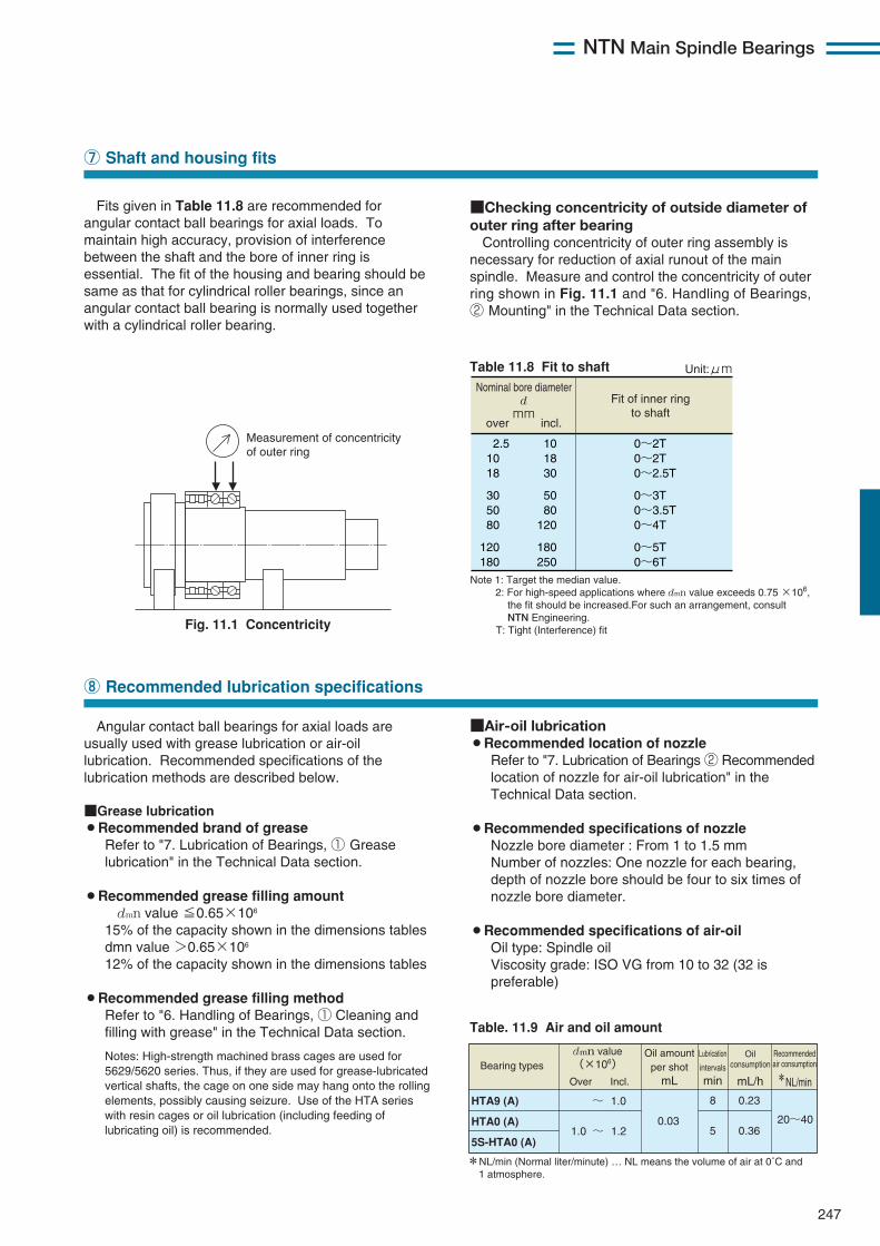
Fits given in Table 11.8 are recommended forangular contact ball bearings for axial loads. Tomaintain high accuracy, provision of interferencebetween the shaft and the bore of inner ring isessential. The fit of the housing and bearing should besame as that for cylindrical roller bearings, since anangular contact ball bearing is normally used togetherwith a cylindrical roller bearing.
NTN Main Spindle Bearings
247
Nominal bore diameter d mm
Fit of inner ring to shaft
2.5 10 18
30 50 80
120 180
10 18 30
50 80
120
180 250
0~2T 0~2T 0~2.5T
0~3T 0~3.5T 0~4T
0~5T 0~6T
over incl.
Unit:μm
Note 1: Target the median value. 2: For high-speed applications where dmn value exceeds 0.75 ×10⁶, the fit should be increased.For such an arrangement, consult NTN Engineering. T: Tight (Interference) fit
Table 11.8 Fit to shaft
⑦ Shaft and housing fits
Angular contact ball bearings for axial loads areusually used with grease lubrication or air-oillubrication. Recommended specifications of thelubrication methods are described below.
■Grease lubrication¡Recommended brand of greaseRefer to "7. Lubrication of Bearings, ① Greaselubrication" in the Technical Data section.
¡Recommended grease filling amountdmn value ≦0.65×10⁶
15% of the capacity shown in the dimensions tablesdmn value >0.65×10⁶
12% of the capacity shown in the dimensions tables
¡Recommended grease filling methodRefer to "6. Handling of Bearings, ① Cleaning andfilling with grease" in the Technical Data section.
Notes: High-strength machined brass cages are used for5629/5620 series. Thus, if they are used for grease-lubricatedvertical shafts, the cage on one side may hang onto the rollingelements, possibly causing seizure. Use of the HTA serieswith resin cages or oil lubrication (including feeding oflubricating oil) is recommended.
⑧ Recommended lubrication specifications
Fig. 11.1 Concentricity
Measurement of concentricity of outer ring
■Air-oil lubrication¡Recommended location of nozzleRefer to "7. Lubrication of Bearings ② Recommendedlocation of nozzle for air-oil lubrication" in theTechnical Data section.
¡Recommended specifications of nozzleNozzle bore diameter : From 1 to 1.5 mmNumber of nozzles: One nozzle for each bearing,depth of nozzle bore should be four to six times ofnozzle bore diameter.
¡Recommended specifications of air-oilOil type: Spindle oilViscosity grade: ISO VG from 10 to 32 (32 ispreferable)
Table. 11.9 Air and oil amount
Recommended air consumption *NL/min
Bearing types
HTA9 (A)
HTA0 (A)
5S-HTA0 (A)
dmn value (×106)
Over Incl.
~ 1.0
1.0 ~ 1.20.03
8
520~40
Oil amount per shot
mL
Lubrication
intervals min
0.23
0.36
mL/h
Oil consumption
*NL/min (Normal liter/minute) … NL means the volume of air at 0˚C and 1 atmosphere.
■Checking concentricity of outside diameter ofouter ring after bearingControlling concentricity of outer ring assembly is
necessary for reduction of axial runout of the mainspindle. Measure and control the concentricity of outerring shown in Fig. 11.1 and "6. Handling of Bearings,② Mounting" in the Technical Data section.
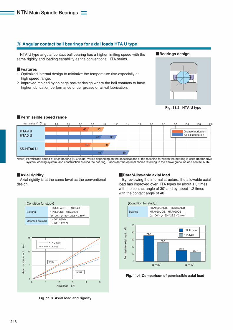
248
NTN Main Spindle Bearings
HTA U type angular contact ball bearing has a higher limiting speed with thesame rigidity and loading capability as the conventional HTA series.
■Features1. Optimized internal design to minimize the temperature rise especially athigh speed range.
2. Improved molded nylon cage pocket design where the ball contacts to havehigher lubrication performance under grease or air-oil lubrication.
⑨ Angular contact ball bearings for axial loads HTA U type
■Permissible speed range
Notes) Permissible speed of each bearing (dmn value) varies depending on the specifications of the machine for which the bearing is used (motor drive system, cooling system, and construction around the bearing). Consider the optimal choice referring to the above guideline and contact NTN.
HTA9 U HTA0 U
5S-HTA0 U
0dmn value×106 0.2 0.4 0.6 0.8 1.0 1.2 1.4 1.6 1.8 2.0 2.2 2.4 2.6 2.8
40˚ 30˚
40˚ 30˚
40˚ 30˚
40˚ 30˚
Grease lubrication Air-oil lubrication
Fig. 11.2 HTA U type
■Bearings design
■Axial rigidityAxial rigidity is at the same level as the conventional
design.
■Data/Allowable axial loadBy reviewing the internal structure, the allowable axial
load has improved over HTA types by about 1.3 timeswith the contact angle of 30˚ and by about 1.2 timeswith the contact angle of 40˚.
Fig. 11.3 Axial load and rigidity
Bearing
Mounted preload
HTA020UADB,HTA020ADB HTA020UDB,HTA020DB (φ100×φ150×22.5×2 row) [α:30˚] 880 N [α:40˚] 1470 N
【Condition for study】
0 1 2 3 4 50
5
10
15
Axi
al d
ispl
acem
ent μ
m
Axial load kN
HTA U type
HTA type
α:30
α:40
100
80
60
40
20
0
Per
mis
sibl
e ax
ial l
oad
kN
Fig. 11.4 Comparison of permissible axial load
HTA U type
HTA type71.3
α=30° α=40°
53.5
31.925.7
Bearing
HTA020UADB,HTA020ADB HTA020UDB,HTA020DB (φ100×φ150×22.5×2 row)
【Condition for study】
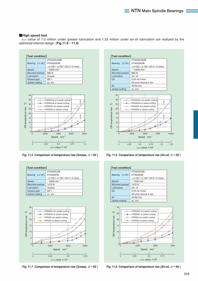
249
NTN Main Spindle Bearings
■High speed testdmn value of 1.0 million under grease lubrication and 1.25 million under air-oil lubrication are realized by the
optimized internal design. (Fig.11.5〜11.8)
Fig. 11.5 Comparison of temperature rise (Grease, α=30˚) Fig. 11.6 Comparison of temperature rise (Air-oil, α=30˚)
Fig. 11.7 Comparison of temperature rise (Grease, α=40˚) Fig. 11.8 Comparison of temperature rise (Air-oil, α=40˚)
Bearing [α:30˚] Speed Mounted preload Lubrication Grease type Jacket coating
HTA020UADB HTA020ADB (φ100×φ150×22.5×2 rows) ~8000 min-1 880 N Grease MP-1 w/, w/o
【Test condition】
Bearing [α:30˚] Speed Mounted preload Lubrication Oil Air Jacket cooling
HTA020UADB HTA020ADB (φ100×φ150×22.5×2 rows) ~10000 min-1 880 N Air- oil 0.03 mL/1shot Oil shot interval 5 min 40 NL/min w/, w/o
【Test condition】
Bearing [α:40˚] Speed Mounted preload Lubrication Grease type Jacket coating
HTA020UDB HTA020DB (φ100×φ150×22.5×2 rows) ~6000 min-1 1470 N Grease MP-1 w/, w/o
【Test condition】
Bearing [α:40˚] Speed Mounted preload Lubrication Oil Air Jacket cooling
HTA020UDB HTA020DB (φ100×φ150×22.5×2 rows) ~7500 min-1 1470 N Air- oil 0.03 mL/1shot Oil shot interval 5 min 40 NL/min w/, w/o
【Test condition】
0 0.25 0.750.5 1.0 1.25
0 2500 5000 7500 10000
40
35
30
25
20
15
10
5
0
Speed min-1
dmn value ×106
OR
tem
pera
ture
ris
e ℃
HTA020A w/o jacket cooling
HTA020UA w/o jacket cooling
HTA020UA w/ jacket cooling
HTA020A w/ jacket cooling
0 2000 4000 6000 8000
Speed min-1
40
35
30
25
20
15
10
5
0
OR
tem
pera
ture
ris
e ℃
0 0.25 0.750.5 1.0
dmn value ×106
0 0.25 0.750.5
dmn value ×106
0 2000 4000 6000
Speed min-1
30
25
20
15
10
5
0
OR
tem
pera
ture
ris
e ℃
0 0.25 0.750.5
dmn value ×106
0 2500 5000 7500
Speed min-1
30
25
20
15
10
5
0
OR
tem
pera
ture
ris
e ℃
HTA020 w/o jacket cooling
HTA020U w/o jacket cooling
HTA020U w/ jacket cooling
HTA020 w/ jacket cooling
HTA020 w/o jacket cooling
HTA020U w/o jacket cooling
HTA020U w/ jacket cooling
HTA020 w/ jacket cooling
HTA020A w/o jacket cooling
HTA020UA w/o jacket cooling
HTA020UA w/ jacket cooling
HTA020A w/ jacket cooling
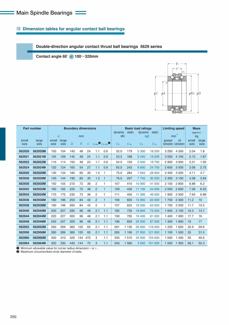
Main Spindle Bearings
250
!0 Dimension tables for angular contact ball bearings
Double-direction angular contact thrust ball bearings 5629 series
Contact angle 60˚ d 100〜320mm
T1
C
φJ
r1
r
φd φEW φD
562920 562920M 100 104 140 48 24 1.1 0.6 52.0 179 5 300 18 200 3 200 4 200 2.04 1.8
562921 562921M 105 109 145 48 24 1.1 0.6 53.5 188 5 450 19 200 3 000 4 100 2.12 1.87
562922 562922M 110 114 150 48 24 1.1 0.6 54.0 193 5 500 19 700 2 900 3 900 2.21 1.95
562924 562924M 120 124 165 54 27 1.1 0.6 65.0 242 6 600 24 700 2 600 3 500 3.06 2.75
562926 562926M 130 134 180 60 30 1.5 1 75.0 284 7 650 28 900 2 400 3 200 4.11 3.7
562928 562928M 140 144 190 60 30 1.5 1 76.0 297 7 750 30 500 2 300 3 100 4.38 3.94
562930 562930M 150 155 210 72 36 2 1 107 410 10 900 41 500 2 100 2 800 6.88 6.2
562932 562932M 160 165 220 72 36 2 1 109 430 11 100 44 000 2 000 2 600 7.26 6.53
562934 562934M 170 175 230 72 36 2 1 111 450 11 300 46 000 1 900 2 500 7.64 6.88
562936 562936M 180 186 250 84 42 2 1 156 605 15 900 62 000 1 700 2 300 11.2 10
562938 562938M 190 196 260 84 42 2 1 157 625 16 000 63 500 1 700 2 200 11.7 10.5
562940 562940M 200 207 280 96 48 2.1 1.1 185 735 18 800 75 000 1 600 2 100 16.3 14.7
562944 562944M 220 227 300 96 48 2.1 1.1 190 795 19 400 81 000 1 400 1 900 17.7 16
562948 562948M 240 247 320 96 48 2.1 1.1 196 850 20 000 87 000 1 300 1 800 19 17
562952 562952M 260 269 360 120 60 2.1 1.1 261 1 130 26 600 116 000 1 200 1 600 32.9 29.6
562956 562956M 280 289 380 120 60 2.1 1.1 265 1 190 27 000 121 000 1 100 1 500 35 31.5
562960 562960M 300 310 420 144 472 3 1.1 335 1 510 34 500 154 000 1 000 1 400 55 49.5
562964 562964M 320 330 440 144 72 3 1.1 340 1 580 3 500 161 000 1 000 1 300 58.1 52.3
Part number Boundary dimensions Basic load ratings Limiting speed Massdynamic static dynamic static (approx.)
d mm kN kgf min-1
kgsmall large small large grease oil small largesize size size size D T1 C rs min1 r1s min1 Ca Coa Ca Coa lubrication lubrication size size
1 Minimum allowable value for corner radius dimension r or r1.2 Maximum circumscribed circle diameter of balls.
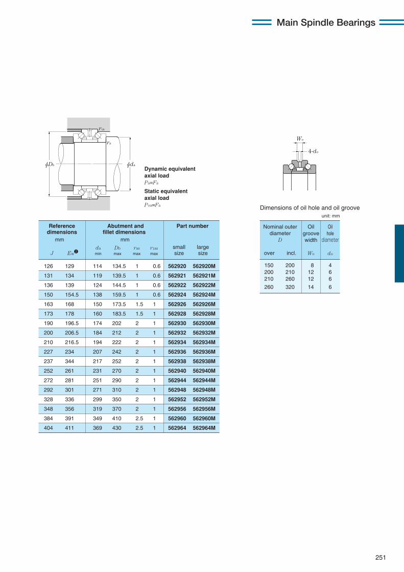
251
Main Spindle Bearings
Dynamic equivalentaxial loadPa=Fa
Static equivalentaxial loadPoa=Fa
126 129 114 134.5 1 0.6 562920 562920M
131 134 119 139.5 1 0.6 562921 562921M
136 139 124 144.5 1 0.6 562922 562922M
150 154.5 138 159.5 1 0.6 562924 562924M
163 168 150 173.5 1.5 1 562926 562926M
173 178 160 183.5 1.5 1 562928 562928M
190 196.5 174 202 2 1 562930 562930M
200 206.5 184 212 2 1 562932 562932M
210 216.5 194 222 2 1 562934 562934M
227 234 207 242 2 1 562936 562936M
237 344 217 252 2 1 562938 562938M
252 261 231 270 2 1 562940 562940M
272 281 251 290 2 1 562944 562944M
292 301 271 310 2 1 562948 562948M
328 336 299 350 2 1 562952 562952M
348 356 319 370 2 1 562956 562956M
384 391 349 410 2.5 1 562960 562960M
404 411 369 430 2.5 1 562964 562964M
Reference Abutment and Part numberdimensions fillet dimensions
mm mm
da Db ras r1as small largeJ Ew2 min max max max size size
φdaφDb
r1a
ra
Nominal outerdiameter
D
over incl.
Oilgroovewidth
Wo
Oilhole
diameter
do
150 200 8 4200 210 12 6210 260 12 6
260 320 14 6
Dimensions of oil hole and oil groove
4-do
Wo
unit: mm
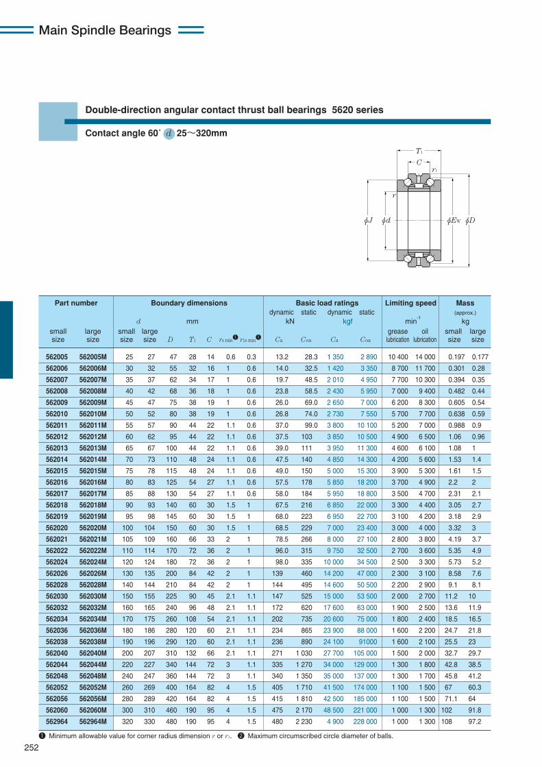
Main Spindle Bearings
252
Double-direction angular contact thrust ball bearings 5620 series
Contact angle 60˚ d 25〜320mm
T1
C
φJ
r1
r
φd φEW φD
562005 562005M 25 27 47 28 14 0.6 0.3 13.2 28.3 1 350 2 890 10 400 14 000 0.197 0.177
562006 562006M 30 32 55 32 16 1 0.6 14.0 32.5 1 420 3 350 8 700 11 700 0.301 0.28
562007 562007M 35 37 62 34 17 1 0.6 19.7 48.5 2 010 4 950 7 700 10 300 0.394 0.35
562008 562008M 40 42 68 36 18 1 0.6 23.8 58.5 2 430 5 950 7 000 9 400 0.482 0.44
562009 562009M 45 47 75 38 19 1 0.6 26.0 69.0 2 650 7 000 6 200 8 300 0.605 0.54
562010 562010M 50 52 80 38 19 1 0.6 26.8 74.0 2 730 7 550 5 700 7 700 0.638 0.59
562011 562011M 55 57 90 44 22 1.1 0.6 37.0 99.0 3 800 10 100 5 200 7 000 0.988 0.9
562012 562012M 60 62 95 44 22 1.1 0.6 37.5 103 3 850 10 500 4 900 6 500 1.06 0.96
562013 562013M 65 67 100 44 22 1.1 0.6 39.0 111 3 950 11 300 4 600 6 100 1.08 1
562014 562014M 70 73 110 48 24 1.1 0.6 47.5 140 4 850 14 300 4 200 5 600 1.53 1.4
562015 562015M 75 78 115 48 24 1.1 0.6 49.0 150 5 000 15 300 3 900 5 300 1.61 1.5
562016 562016M 80 83 125 54 27 1.1 0.6 57.5 178 5 850 18 200 3 700 4 900 2.2 2
562017 562017M 85 88 130 54 27 1.1 0.6 58.0 184 5 950 18 800 3 500 4 700 2.31 2.1
562018 562018M 90 93 140 60 30 1.5 1 67.5 216 6 850 22 000 3 300 4 400 3.05 2.7
562019 562019M 95 98 145 60 30 1.5 1 68.0 223 6 950 22 700 3 100 4 200 3.18 2.9
562020 562020M 100 104 150 60 30 1.5 1 68.5 229 7 000 23 400 3 000 4 000 3.32 3
562021 562021M 105 109 160 66 33 2 1 78.5 266 8 000 27 100 2 800 3 800 4.19 3.7
562022 562022M 110 114 170 72 36 2 1 96.0 315 9 750 32 500 2 700 3 600 5.35 4.9
562024 562024M 120 124 180 72 36 2 1 98.0 335 10 000 34 500 2 500 3 300 5.73 5.2
562026 562026M 130 135 200 84 42 2 1 139 460 14 200 47 000 2 300 3 100 8.58 7.6
562028 562028M 140 144 210 84 42 2 1 144 495 14 600 50 500 2 200 2 900 9.1 8.1
562030 562030M 150 155 225 90 45 2.1 1.1 147 525 15 000 53 500 2 000 2 700 11.2 10
562032 562032M 160 165 240 96 48 2.1 1.1 172 620 17 600 63 000 1 900 2 500 13.6 11.9
562034 562034M 170 175 260 108 54 2.1 1.1 202 735 20 600 75 000 1 800 2 400 18.5 16.5
562036 562036M 180 186 280 120 60 2.1 1.1 234 865 23 900 88 000 1 600 2 200 24.7 21.8
562038 562038M 190 196 290 120 60 2.1 1.1 236 890 24 100 91000 1 600 2 100 25.5 23
562040 562040M 200 207 310 132 66 2.1 1.1 271 1 030 27 700 105 000 1 500 2 000 32.7 29.7
562044 562044M 220 227 340 144 72 3 1.1 335 1 270 34 000 129 000 1 300 1 800 42.8 38.5
562048 562048M 240 247 360 144 72 3 1.1 340 1 350 35 000 137 000 1 300 1 700 45.8 41.2
562052 562052M 260 269 400 164 82 4 1.5 405 1 710 41 500 174 000 1 100 1 500 67 60.3
562056 562056M 280 289 420 164 82 4 1.5 415 1 810 42 500 185 000 1 100 1 500 71.1 64
562060 562060M 300 310 460 190 95 4 1.5 475 2 170 48 500 221 000 1 000 1 300 102 91.8
562964 562964M 320 330 480 190 95 4 1.5 480 2 230 4 900 228 000 1 000 1 300 108 97.2
Part number Boundary dimensions Basic load ratings Limiting speed Massdynamic static dynamic static (approx.)
d mm kN kgf min-1
kgsmall large small large grease oil small largesize size size size D T1 C rs min1 r1s min1 Ca Coa Ca Coa lubrication lubrication size size
1 Minimum allowable value for corner radius dimension r or r1. 2 Maximum circumscribed circle diameter of balls.
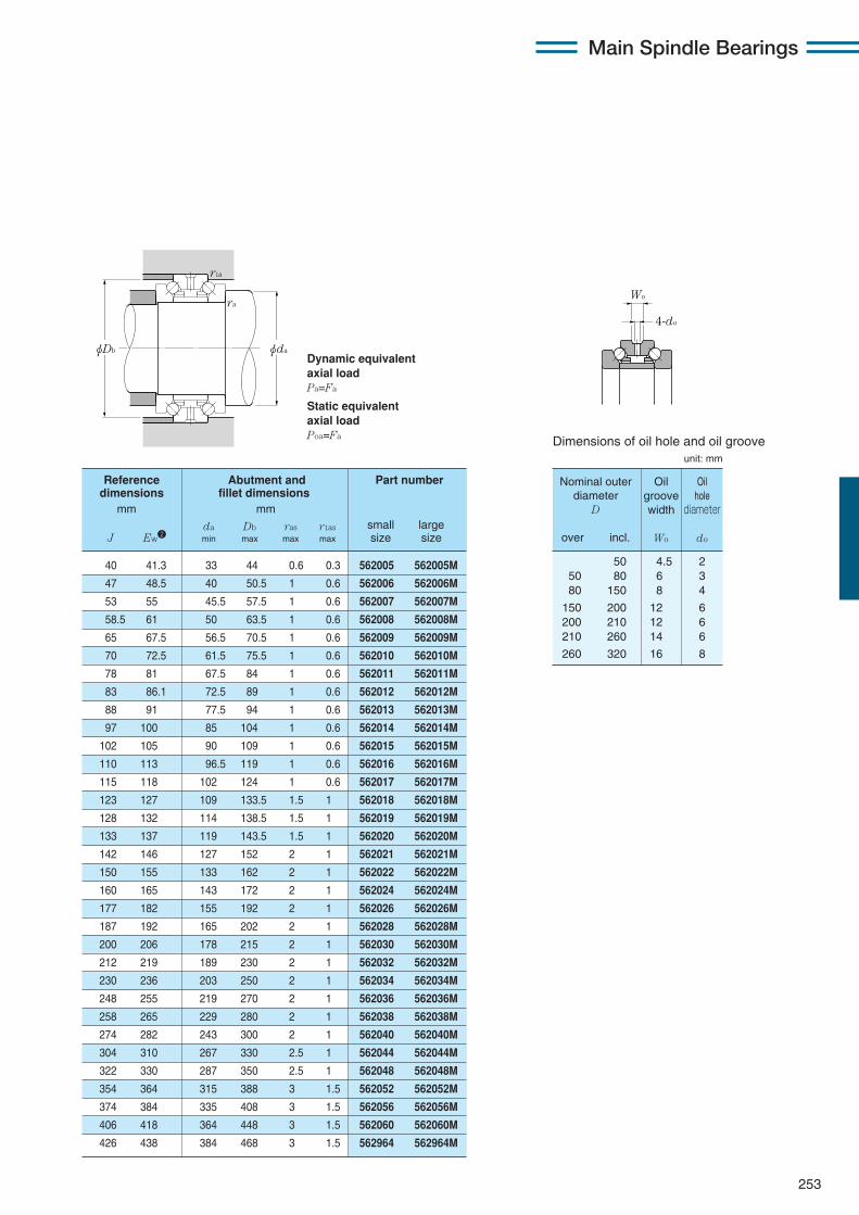
253
Main Spindle Bearings
Dynamic equivalentaxial loadPa=Fa
Static equivalentaxial loadPoa=Fa
40 41.3 33 44 0.6 0.3 562005 562005M
47 48.5 40 50.5 1 0.6 562006 562006M
53 55 45.5 57.5 1 0.6 562007 562007M
58.5 61 50 63.5 1 0.6 562008 562008M
65 67.5 56.5 70.5 1 0.6 562009 562009M
70 72.5 61.5 75.5 1 0.6 562010 562010M
78 81 67.5 84 1 0.6 562011 562011M
83 86.1 72.5 89 1 0.6 562012 562012M
88 91 77.5 94 1 0.6 562013 562013M
97 100 85 104 1 0.6 562014 562014M
102 105 90 109 1 0.6 562015 562015M
110 113 96.5 119 1 0.6 562016 562016M
115 118 102 124 1 0.6 562017 562017M
123 127 109 133.5 1.5 1 562018 562018M
128 132 114 138.5 1.5 1 562019 562019M
133 137 119 143.5 1.5 1 562020 562020M
142 146 127 152 2 1 562021 562021M
150 155 133 162 2 1 562022 562022M
160 165 143 172 2 1 562024 562024M
177 182 155 192 2 1 562026 562026M
187 192 165 202 2 1 562028 562028M
200 206 178 215 2 1 562030 562030M
212 219 189 230 2 1 562032 562032M
230 236 203 250 2 1 562034 562034M
248 255 219 270 2 1 562036 562036M
258 265 229 280 2 1 562038 562038M
274 282 243 300 2 1 562040 562040M
304 310 267 330 2.5 1 562044 562044M
322 330 287 350 2.5 1 562048 562048M
354 364 315 388 3 1.5 562052 562052M
374 384 335 408 3 1.5 562056 562056M
406 418 364 448 3 1.5 562060 562060M
426 438 384 468 3 1.5 562964 562964M
Reference Abutment and Part numberdimensions fillet dimensions
mm mm
da Db ras r1as small largeJ Ew2 min max max max size size
φdaφDb
r1a
ra
4-do
Wo
Dimensions of oil hole and oil grooveunit: mm
50 4.5 250 80 6 380 150 8 4
150 200 12 6200 210 12 6210 260 14 6
260 320 16 8
Nominal outerdiameter
D
over incl.
Oilgroovewidth
Wo
Oilhole
diameter
do

Main Spindle Bearings
254
Angular contact ball bearings for axial loads (steel ball type) HTA9UA series
Contact angle 30˚ d 100〜320mm
φD φdφd1φD2
2a
2B
r r
r1 r 1
HTA920UADB 100 140 36 1.1 0.6 40.0 109 4 050 11 100 66.0 6 750 8 300 10 400
HTA921UADB 105 145 36 1.1 0.6 41.0 115 4 150 11 700 70.0 7 150 8 000 10 000
HTA922UADB 110 150 36 1.1 0.6 41.5 118 4 200 12 000 72.0 7 350 7 700 9 600
HTA924UADB 120 165 40.5 1.1 0.6 48.0 140 4 900 14 300 87.5 8 900 7 000 8 800
HTA926UADB 130 180 45 1.5 1 57.5 173 5 850 17 600 103 10 500 6 500 8 100
HTA928UADB 140 190 45 1.5 1 57.5 177 5 850 18 000 106 10 800 6 100 7 600
HTA930UADB 150 210 54 2 1 80.5 243 8 200 24 800 143 14 600 5 600 6 900
HTA932UADB 160 220 54 2 1 82.0 255 8 350 26 100 151 15 400 5 300 6 600
HTA934UADB 170 230 54 2 1 84.0 268 8 550 27 300 159 16 200 5 000 6 300
HTA936UADB 180 250 63 2 1 127 400 12 900 41 000 239 24 400 4 700 5 800
HTA938UADB 190 260 63 2 1 129 420 13 200 43 000 252 25 700 4 400 5 600
HTA940UADB 200 280 72 2.1 1.1 152 500 15 500 51 000 305 31 000 4 200 5 200
HTA944UADB 220 300 72 2.1 1.1 156 535 15 900 54 500 330 33 500 3 800 4 800
HTA948UADB 240 320 72 2.1 1.1 160 570 16 300 58 000 350 35 500 3 600 4 500
HTA952UADB 260 360 90 2.1 1.1 210 745 21 400 76 000 460 47 000 3 200 4 000
HTA956UADB 280 380 90 2.1 1.1 216 795 22 000 81 000 490 50 000 3 000 3 800
HTA960UADB 300 420 108 3 1.1 276 1 020 28 100 104 000 610 62 000 2 800 3 500
HTA964UADB 320 440 108 3 1.1 280 1 060 28 500 108 000 635 65 000 2 600 3 300
Part Boundary dimensions Basic load ratings Static thrust Limiting speednumber dynamic static dynamic static load capacity
mm kN kgf kN kgf min-1
grease oild D 2B rs min1 r1s min1 Ca Coa Ca Coa lubrication lubrication
1 Minimum allowable value for corner radius dimension r or r1.

255
Main Spindle Bearings
Dynamic equivalentaxial loadPa=Fa
Static equivalentaxial loadPoa=Fa
φdaφDb
r1as
ras
87.6 24 0.81 115.3 129.1 110 134 1 0.6 HTA920UADB
90.5 24 0.85 120.3 134.1 115 139 1 0.6 HTA921UADB
93.4 26 0.88 125.3 139.1 120 144 1 0.6 HTA922UADB
102.9 36 1.23 137.4 152.4 130 159 1 0.6 HTA924UADB
112.4 50 1.65 149.4 165.8 142 172.5 1.5 1 HTA926UADB
118.1 53 1.75 159.4 175.8 152 182.5 1.5 1 HTA928UADB
131.4 85 2.74 173.1 193.3 164 202.5 2 1 HTA930UADB
137.1 90 2.89 183.1 203.3 174 212.5 2 1 HTA932UADB
142.9 94 3.05 193.1 213.2 184 222.5 2 1 HTA934UADB
156.2 138 4.78 206.4 231.5 194 242.5 2 1 HTA936UADB
162.0 144 5.00 216.4 241.5 204 252.5 2 1 HTA938UADB
175.2 197 7.00 230.6 258.2 217 270 2 1 HTA940UADB
186.7 213 7.60 250.6 277.9 237 290 2 1 HTA944UADB
198.3 229 8.15 270.6 297.9 257 310 2 1 HTA948UADB
224.7 378 14.3 298.9 331.6 277 350 2 1 HTA952UADB
236.3 403 15.2 318.9 351.4 297 370 2 1 HTA956UADB
262.7 675 23.5 347.1 385.2 320 410 2.5 1 HTA960UADB
274.2 715 24.8 367.1 405.0 340 430 2.5 1 HTA964UADB
Load Internal Mass Reference Abutment and fillet dimensions Partcenter free space dimensions number
mm cm3 kg mm mm
Two row Two row da Db ras r1as2a (approx.) (approx.) d1 D2 min max max max
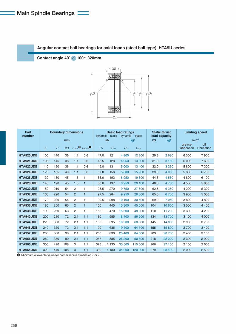
Main Spindle Bearings
256
Angular contact ball bearings for axial loads (steel ball type) HTA9U series
Contact angle 40˚ d 100〜320mm
φD φdφd1φD2
2a
2B
r r
r1 r 1
HTA920UDB 100 140 36 1.1 0.6 47.0 121 4 800 12 300 29.3 2 990 6 300 7 900
HTA921UDB 105 145 36 1.1 0.6 48.5 128 4 950 13 000 31.0 3 150 6 000 7 600
HTA922UDB 110 150 36 1.1 0.6 49.0 131 5 000 13 400 32.0 3 250 5 800 7 300
HTA924UDB 120 165 40.5 1.1 0.6 57.0 156 5 800 15 900 39.0 4 000 5 300 6 700
HTA926UDB 130 180 45 1.5 1 68.0 193 6 950 19 600 44.5 4 550 4 800 6 100
HTA928UDB 140 190 45 1.5 1 68.0 197 6 950 20 100 46.0 4 700 4 500 5 800
HTA930UDB 150 210 54 2 1 95.5 270 9 750 27 600 62.5 6 350 4 200 5 300
HTA932UDB 160 220 54 2 1 97.5 284 9 950 29 000 65.5 6 700 3 900 5 000
HTA934UDB 170 230 54 2 1 99.5 298 10 100 30 500 69.0 7 050 3 800 4 800
HTA936UDB 180 250 63 2 1 150 445 15 300 45 500 104 10 600 3 500 4 400
HTA938UDB 190 260 63 2 1 153 470 15 600 48 000 110 11 200 3 300 4 200
HTA940UDB 200 280 72 2.1 1.1 180 555 18 400 56 500 134 13 700 3 100 4 000
HTA944UDB 220 300 72 2.1 1.1 185 595 18 900 60 500 145 14 800 2 900 3 700
HTA948UDB 240 320 72 2.1 1.1 190 635 19 400 64 500 155 15 800 2 700 3 400
HTA952UDB 260 360 90 2.1 1.1 250 830 25 400 84 500 203 20 700 2 400 3 100
HTA956UDB 280 380 90 2.1 1.1 257 885 26 200 90 500 218 22 200 2 300 2 900
HTA960UDB 300 420 108 3 1.1 325 1 130 33 500 115 000 266 27 100 2 100 2 600
HTA964UDB 320 440 108 3 1.1 330 1 180 34 000 120 000 279 28 400 2 000 2 500
Part Boundary dimensions Basic load ratings Static thrust Limiting speednumber dynamic static dynamic static load capacity
mm kN kgf kN kgf min-1
grease oild D 2B rs min1 r1s min1 Ca Coa Ca Coa lubrication lubrication
1 Minimum allowable value for corner radius dimension r or r1.
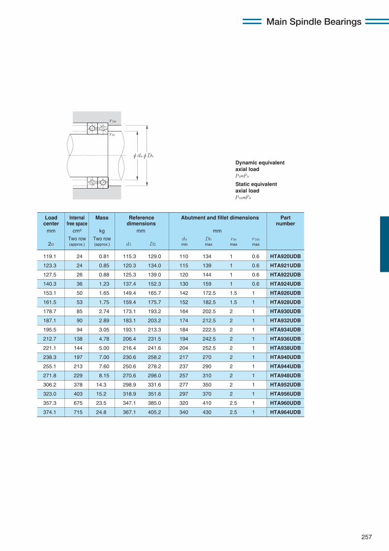
257
Main Spindle Bearings
Dynamic equivalentaxial loadPa=Fa
Static equivalentaxial loadPoa=Fa
φdaφDb
r1as
ras
119.1 24 0.81 115.3 129.0 110 134 1 0.6 HTA920UDB
123.3 24 0.85 120.3 134.0 115 139 1 0.6 HTA921UDB
127.5 26 0.88 125.3 139.0 120 144 1 0.6 HTA922UDB
140.3 36 1.23 137.4 152.3 130 159 1 0.6 HTA924UDB
153.1 50 1.65 149.4 165.7 142 172.5 1.5 1 HTA926UDB
161.5 53 1.75 159.4 175.7 152 182.5 1.5 1 HTA928UDB
178.7 85 2.74 173.1 193.2 164 202.5 2 1 HTA930UDB
187.1 90 2.89 183.1 203.2 174 212.5 2 1 HTA932UDB
195.5 94 3.05 193.1 213.3 184 222.5 2 1 HTA934UDB
212.7 138 4.78 206.4 231.5 194 242.5 2 1 HTA936UDB
221.1 144 5.00 216.4 241.6 204 252.5 2 1 HTA938UDB
238.3 197 7.00 230.6 258.2 217 270 2 1 HTA940UDB
255.1 213 7.60 250.6 278.2 237 290 2 1 HTA944UDB
271.8 229 8.15 270.6 298.0 257 310 2 1 HTA948UDB
306.2 378 14.3 298.9 331.6 277 350 2 1 HTA952UDB
323.0 403 15.2 318.9 351.6 297 370 2 1 HTA956UDB
357.3 675 23.5 347.1 385.0 320 410 2.5 1 HTA960UDB
374.1 715 24.8 367.1 405.2 340 430 2.5 1 HTA964UDB
Load Internal Mass Reference Abutment and fillet dimensions Partcenter free space dimensions number
mm cm3 kg mm mm
Two row Two row da Db ras r1as2a (approx.) (approx.) d1 D2 min max max max

Main Spindle Bearings
258
Angular contact ball bearings for axial loads (steel ball type) HTA0UA series
Contact angle 30˚ d 50〜320mm
φD φdφd1φD2
2a
2B
r r
r1 r 1
HTA010UADB 50 80 28.5 1 0.6 24.7 48.5 2 520 4 950 23.2 2 370 15 400 19 200
HTA011UADB 55 90 33 1.1 0.6 26.8 57.5 2 730 5 850 27.7 2 820 13 800 17 200
HTA012UADB 60 95 33 1.1 0.6 28.1 63.0 2 860 6 400 30.5 3 100 12 900 16 100
HTA013UADB 65 100 33 1.1 0.6 28.5 65.0 2 900 6 650 32.0 3 250 12 100 15 200
HTA014UADB 70 110 36 1.1 0.6 35.0 82.0 3 550 8 350 40.0 4 100 11 100 13 900
HTA015UADB 75 115 36 1.1 0.6 37.0 91.5 3 800 9 300 45.5 4 650 10 500 13 200
HTA016UADB 80 125 40.5 1.1 0.6 42.5 105 4 350 10 700 52.0 5 300 9 800 12 200
HTA017UADB 85 130 40.5 1.1 0.6 43.0 108 4 400 11 100 54.5 5 550 9 300 11 600
HTA018UADB 90 140 45 1.5 1 50.0 127 5 100 13 000 63.5 6 500 8 700 10 900
HTA019UADB 95 145 45 1.5 1 50.5 131 5 150 13 400 66.0 6 750 8 300 10 400
HTA020UADB 100 150 45 1.5 1 52.5 140 5 350 14 300 71.0 7 250 8 000 10 000
HTA021UADB 105 160 49.5 2 1 60.0 163 6 100 16 600 82.5 8 400 7 500 9 400
HTA022UADB 110 170 54 2 1 74.5 200 7 600 20 400 100 10 200 7 100 8 900
HTA024UADB 120 180 54 2 1 75.0 206 7 650 21 000 104 10 600 6 700 8 300
HTA026UADB 130 200 63 2 1 108 293 11 000 29 900 144 14 700 6 100 7 600
HTA028UADB 140 210 63 2 1 111 315 11 300 32 000 156 15 900 5 700 7 100
HTA030UADB 150 225 67.5 2.1 1.1 114 330 11 700 34 000 169 17 200 5 300 6 700
HTA032UADB 160 240 72 2.1 1.1 134 390 13 700 40 000 196 20 000 5 000 6 300
HTA034UADB 170 260 81 2.1 1.1 153 450 15 900 46 000 226 23 000 4 700 5 800
HTA036UADB 180 280 90 2.1 1.1 177 530 18 100 54 000 265 27 000 4 300 5 400
HTA038UADB 190 290 91 2.1 1.1 179 545 18 300 55 500 275 28 000 4 200 5 200
HTA040UADB 200 310 99 2.1 1.1 201 610 20 500 62 000 310 31 500 3 900 4 900
HTA044UADB 220 340 108 3 1.1 253 775 25 800 79 000 385 39 500 3 600 4 500
HTA048UADB 240 360 108 3 1.1 261 825 26 600 84 000 415 42 500 3 300 4 200
HTA052UADB 260 400 123 4 1.5 310 1040 31 500 106 000 520 53 500 3 000 3 800
HTA056UADB 280 420 123 4 1.5 315 1110 32 500 113 000 565 57 500 2 900 3 600
HTA060UADB 300 460 142.5 4 1.5 360 1330 37 000 135 000 670 68 500 2 600 3 300
HTA064UADB 320 480 142.5 4 1.5 365 1360 37 000 139 000 700 71 500 2 500 3 100
Part Boundary dimensions Basic load ratings Static thrust Limiting speednumber dynamic static dynamic static load capacity
mm kN kgf kN kgf min-1
grease oild D 2B rs min1 r1s min1 Ca Coa Ca Coa lubrication lubrication
1 Minimum allowable value for corner radius dimension r or r1.
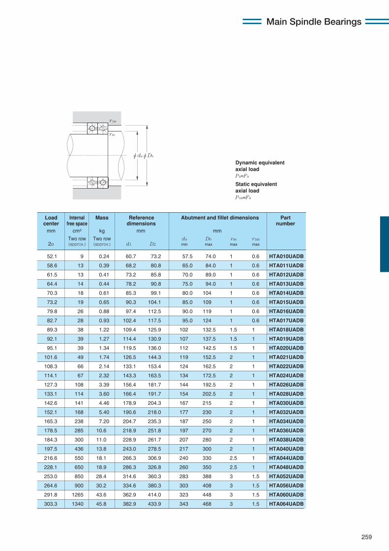
259
Main Spindle Bearings
Dynamic equivalentaxial loadPa=Fa
Static equivalentaxial loadPoa=Fa
φdaφDb
r1as
ras
52.1 9 0.24 60.7 73.2 57.5 74.0 1 0.6 HTA010UADB
58.6 13 0.39 68.2 80.8 65.0 84.0 1 0.6 HTA011UADB
61.5 13 0.41 73.2 85.8 70.0 89.0 1 0.6 HTA012UADB
64.4 14 0.44 78.2 90.8 75.0 94.0 1 0.6 HTA013UADB
70.3 18 0.61 85.3 99.1 80.0 104 1 0.6 HTA014UADB
73.2 19 0.65 90.3 104.1 85.0 109 1 0.6 HTA015UADB
79.8 26 0.88 97.4 112.5 90.0 119 1 0.6 HTA016UADB
82.7 28 0.93 102.4 117.5 95.0 124 1 0.6 HTA017UADB
89.3 38 1.22 109.4 125.9 102 132.5 1.5 1 HTA018UADB
92.1 39 1.27 114.4 130.9 107 137.5 1.5 1 HTA019UADB
95.1 39 1.34 119.5 136.0 112 142.5 1.5 1 HTA020UADB
101.6 49 1.74 126.5 144.3 119 152.5 2 1 HTA021UADB
108.3 66 2.14 133.1 153.4 124 162.5 2 1 HTA022UADB
114.1 67 2.32 143.3 163.5 134 172.5 2 1 HTA024UADB
127.3 108 3.39 156.4 181.7 144 192.5 2 1 HTA026UADB
133.1 114 3.60 166.4 191.7 154 202.5 2 1 HTA028UADB
142.6 141 4.46 178.9 204.3 167 215 2 1 HTA030UADB
152.1 168 5.40 190.6 218.0 177 230 2 1 HTA032UADB
165.3 238 7.20 204.7 235.3 187 250 2 1 HTA034UADB
178.5 285 10.6 218.9 251.8 197 270 2 1 HTA036UADB
184.3 300 11.0 228.9 261.7 207 280 2 1 HTA038UADB
197.5 436 13.8 243.0 278.5 217 300 2 1 HTA040UADB
216.6 550 18.1 266.3 306.9 240 330 2.5 1 HTA044UADB
228.1 650 18.9 286.3 326.8 260 350 2.5 1 HTA048UADB
253.0 850 28.4 314.6 360.3 283 388 3 1.5 HTA052UADB
264.6 900 30.2 334.6 380.3 303 408 3 1.5 HTA056UADB
291.8 1265 43.6 362.9 414.0 323 448 3 1.5 HTA060UADB
303.3 1340 45.8 382.9 433.9 343 468 3 1.5 HTA064UADB
Load Internal Mass Reference Abutment and fillet dimensions Partcenter free space dimensions number
mm cm3 kg mm mm
Two row Two row da Db ras r1as2a (approx.) (approx.) d1 D2 min max max max
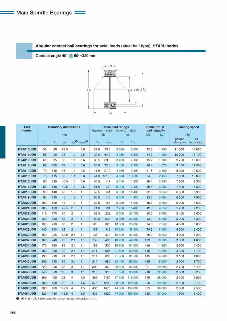
Main Spindle Bearings
260
Angular contact ball bearings for axial loads (steel ball type) HTA0U series
Contact angle 40˚ d 50〜320mm
φD φdφd1φD2
2a
2B
r r
r1 r 1
HTA010UDB 50 80 28.5 1 0.6 29.6 55.5 3 000 5 650 12.3 1 250 11 500 14 600
HTA011UDB 55 90 33 1.1 0.6 32.0 64.0 3 250 6 500 14.3 1 460 10 300 13 100
HTA012UDB 60 95 33 1.1 0.6 33.5 69.5 3 400 7 100 15.7 1 600 9 700 12 300
HTA013UDB 65 100 33 1.1 0.6 34.0 72.0 3 450 7 350 16.4 1 670 9 100 11 500
HTA014UDB 70 110 36 1.1 0.6 41.5 91.0 4 250 9 300 21.5 2 190 8 300 10 600
HTA015UDB 75 115 36 1.1 0.6 44.0 101.0 4 500 10 300 24.0 2 450 7 900 10 000
HTA016UDB 80 125 40.5 1.1 0.6 50.5 117 5 150 11 900 28.4 2 900 7 300 9 300
HTA017UDB 85 130 40.5 1.1 0.6 51.0 120 5 200 12 300 29.4 3 000 7 000 8 800
HTA018UDB 90 140 45 1.5 1 59.5 141 6 050 14 400 32.0 3 250 6 500 8 300
HTA019UDB 95 145 45 1.5 1 60.0 146 6 100 14 900 33.5 3 400 6 300 7 900
HTA020UDB 100 150 45 1.5 1 62.0 156 6 350 15 900 35.5 3 600 6 000 7 600
HTA021UDB 105 160 49.5 2 1 71.0 181 7 250 18 400 42.5 4 350 5 700 7 200
HTA022UDB 110 170 54 2 1 88.5 222 9 000 22 700 50.0 5 100 5 400 6 800
HTA024UDB 120 180 54 2 1 89.0 228 9 050 23 300 52.0 5 300 5 000 6 300
HTA026UDB 130 200 63 2 1 128 325 13 000 33 000 74.0 7 550 4 500 5 800
HTA028UDB 140 210 63 2 1 132 345 13 500 35 500 79.5 8 100 4 300 5 400
HTA030UDB 150 225 67.5 2.1 1.1 136 370 13 800 37 500 85.0 8 650 4 000 5 200
HTA032UDB 160 240 72 2.1 1.1 159 435 16 200 44 000 103 10 500 3 800 4 800
HTA034UDB 170 260 81 2.1 1.1 182 500 18 600 51 000 116 11 800 3 500 4 400
HTA036UDB 180 280 90 2.1 1.1 211 585 21 500 60 000 140 14 300 3 300 4 100
HTA038UDB 190 290 91 2.1 1.1 214 605 21 800 61 500 145 14 800 3 100 4 000
HTA040UDB 200 310 99 2.1 1.1 240 680 24 400 69 000 159 16 200 2 900 3 700
HTA044UDB 220 340 108 3 1.1 300 860 30 500 87 500 201 20 500 2 700 3 400
HTA048UDB 240 360 108 3 1.1 310 915 31 500 93 000 216 22 000 2 500 3 200
HTA052UDB 260 400 123 4 1.5 365 1160 37 500 118 000 275 28 000 2 300 2 900
HTA056UDB 280 420 123 4 1.5 375 1230 38 500 125 000 293 29 900 2 100 2 700
HTA060UDB 300 460 142.5 4 1.5 430 1470 44 000 150 000 355 36 000 2 000 2 500
HTA064UDB 320 480 142.5 4 1.5 435 1520 44 000 155 000 365 37 000 1 900 2 400
Part Boundary dimensions Basic load ratings Static thrust Limiting speednumber dynamic static dynamic static load capacity
mm kN kgf kN kgf min-1
grease oild D 2B rs min1 r1s min1 Ca Coa Ca Coa lubrication lubrication
1 Minimum allowable value for corner radius dimension r or r1.

261
Main Spindle Bearings
Dynamic equivalentaxial loadPa=Fa
Static equivalentaxial loadPoa=Fa
φdaφDb
r1as
ras
69.2 9 0.24 60.7 73.1 57.5 74.0 1 0.6 HTA010UDB
77.7 13 0.39 68.2 80.7 65.0 84.0 1 0.6 HTA011UDB
81.9 13 0.41 73.2 85.7 70.0 89.0 1 0.6 HTA012UDB
86.1 14 0.44 78.2 90.7 75.0 94.0 1 0.6 HTA013UDB
94.0 18 0.61 85.3 99.0 80.0 104 1 0.6 HTA014UDB
98.2 19 0.65 90.3 104.0 85.0 109 1 0.6 HTA015UDB
106.7 26 0.88 97.4 112.4 90.0 119 1 0.6 HTA016UDB
110.9 28 0.93 102.4 117.4 95.0 124 1 0.6 HTA017UDB
119.5 38 1.22 109.4 125.8 102 132.5 1.5 1 HTA018UDB
123.7 39 1.27 114.4 130.8 107 137.5 1.5 1 HTA019UDB
128.0 39 1.34 119.5 135.9 112 142.5 1.5 1 HTA020UDB
136.5 49 1.74 126.5 144.2 119 152.5 2 1 HTA021UDB
145.1 66 2.14 133.1 153.3 124 162.5 2 1 HTA022UDB
153.6 67 2.32 143.3 163.4 134 172.5 2 1 HTA024UDB
170.8 108 3.39 156.4 181.6 144 192.5 2 1 HTA026UDB
179.2 114 3.60 166.4 191.6 154 202.5 2 1 HTA028UDB
191.9 141 4.46 178.9 204.2 167 215 2 1 HTA030UDB
204.7 168 5.40 190.6 218.4 177 230 2 1 HTA032UDB
221.9 238 7.20 204.7 235.2 187 250 2 1 HTA034UDB
239.1 285 10.6 218.9 251.6 197 270 2 1 HTA036UDB
247.4 300 11.0 228.9 261.6 207 280 2 1 HTA038UDB
264.6 436 13.8 243.0 278.4 217 300 2 1 HTA040UDB
290.3 550 18.1 266.3 306.7 240 330 2.5 1 HTA044UDB
307.0 650 18.9 286.3 326.6 260 350 2.5 1 HTA048UDB
339.9 850 28.4 314.6 360.1 283 388 3 1.5 HTA052UDB
356.7 900 30.2 334.6 380.1 303 408 3 1.5 HTA056UDB
391.7 1265 43.6 362.9 413.7 323 448 3 1.5 HTA060UDB
408.5 1340 45.8 382.9 433.7 343 468 3 1.5 HTA064UDB
Load Internal Mass Reference Abutment and fillet dimensions Partcenter free space dimensions number
mm cm3 kg mm mm
Two row Two row da Db ras r1as2a (approx.) (approx.) d1 D2 min max max max
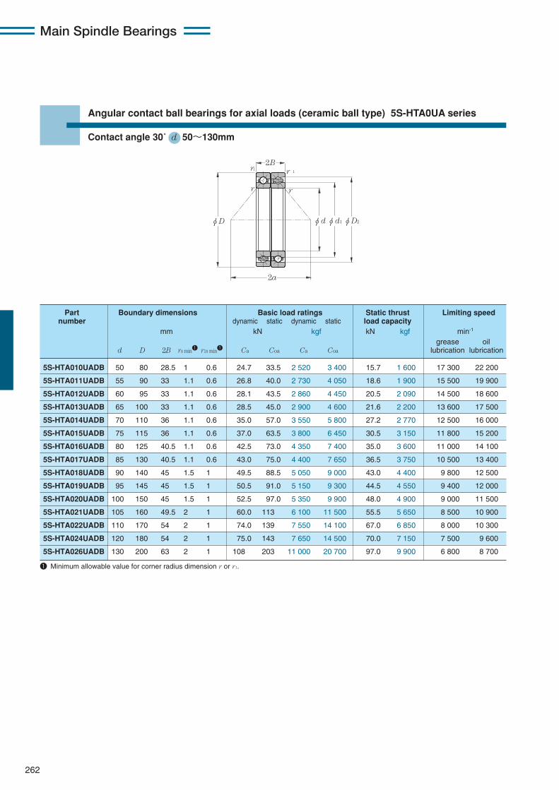
Main Spindle Bearings
262
Angular contact ball bearings for axial loads (ceramic ball type) 5S-HTA0UA series
Contact angle 30˚ d 50〜130mm
φD φdφd1φD2
2a
2B
r r
r1 r 1
5S-HTA010UADB 50 80 28.5 1 0.6 24.7 33.5 2 520 3 400 15.7 1 600 17 300 22 200
5S-HTA011UADB 55 90 33 1.1 0.6 26.8 40.0 2 730 4 050 18.6 1 900 15 500 19 900
5S-HTA012UADB 60 95 33 1.1 0.6 28.1 43.5 2 860 4 450 20.5 2 090 14 500 18 600
5S-HTA013UADB 65 100 33 1.1 0.6 28.5 45.0 2 900 4 600 21.6 2 200 13 600 17 500
5S-HTA014UADB 70 110 36 1.1 0.6 35.0 57.0 3 550 5 800 27.2 2 770 12 500 16 000
5S-HTA015UADB 75 115 36 1.1 0.6 37.0 63.5 3 800 6 450 30.5 3 150 11 800 15 200
5S-HTA016UADB 80 125 40.5 1.1 0.6 42.5 73.0 4 350 7 400 35.0 3 600 11 000 14 100
5S-HTA017UADB 85 130 40.5 1.1 0.6 43.0 75.0 4 400 7 650 36.5 3 750 10 500 13 400
5S-HTA018UADB 90 140 45 1.5 1 49.5 88.5 5 050 9 000 43.0 4 400 9 800 12 500
5S-HTA019UADB 95 145 45 1.5 1 50.5 91.0 5 150 9 300 44.5 4 550 9 400 12 000
5S-HTA020UADB 100 150 45 1.5 1 52.5 97.0 5 350 9 900 48.0 4 900 9 000 11 500
5S-HTA021UADB 105 160 49.5 2 1 60.0 113 6 100 11 500 55.5 5 650 8 500 10 900
5S-HTA022UADB 110 170 54 2 1 74.0 139 7 550 14 100 67.0 6 850 8 000 10 300
5S-HTA024UADB 120 180 54 2 1 75.0 143 7 650 14 500 70.0 7 150 7 500 9 600
5S-HTA026UADB 130 200 63 2 1 108 203 11 000 20 700 97.0 9 900 6 800 8 700
Part Boundary dimensions Basic load ratings Static thrust Limiting speednumber dynamic static dynamic static load capacity
mm kN kgf kN kgf min-1
grease oild D 2B rs min1 r1s min1 Ca Coa Ca Coa lubrication lubrication
1 Minimum allowable value for corner radius dimension r or r1.
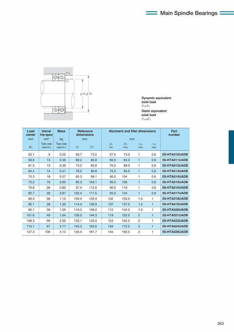
263
Main Spindle Bearings
Dynamic equivalentaxial loadPa=Fa
Static equivalentaxial loadPoa=Fa
φdaφDb
r1as
ras
52.1 9 0.22 60.7 73.2 57.5 74.0 1 0.6 5S-HTA010UADB
58.6 13 0.36 68.2 80.8 65.0 84.0 1 0.6 5S-HTA011UADB
61.5 13 0.39 73.2 85.8 70.0 89.0 1 0.6 5S-HTA012UADB
64.4 14 0.41 78.2 90.8 75.0 94.0 1 0.6 5S-HTA013UADB
70.3 18 0.57 85.3 99.1 80.0 104 1 0.6 5S-HTA014UADB
73.2 19 0.60 90.3 104.1 85.0 109 1 0.6 5S-HTA015UADB
79.8 26 0.83 97.4 112.5 90.0 119 1 0.6 5S-HTA016UADB
82.7 28 0.87 102.4 117.5 95.0 124 1 0.6 5S-HTA017UADB
89.3 38 1.15 109.4 125.9 102 132.5 1.5 1 5S-HTA018UADB
92.1 39 1.20 114.4 130.9 107 137.5 1.5 1 5S-HTA019UADB
95.1 39 1.26 119.5 136.0 112 142.5 1.5 1 5S-HTA020UADB
101.6 49 1.64 126.5 144.3 119 152.5 2 1 5S-HTA021UADB
108.3 66 2.00 133.1 153.4 124 162.5 2 1 5S-HTA022UADB
114.1 67 2.17 143.3 163.5 134 172.5 2 1 5S-HTA024UADB
127.3 108 3.13 156.4 181.7 144 192.5 2 1 5S-HTA026UADB
Load Internal Mass Reference Abutment and fillet dimensions Partcenter free space dimensions number
mm cm3 kg mm mm
Two row Two row da Db ras r1as2a (approx.) (approx.) d1 D2 min max max max
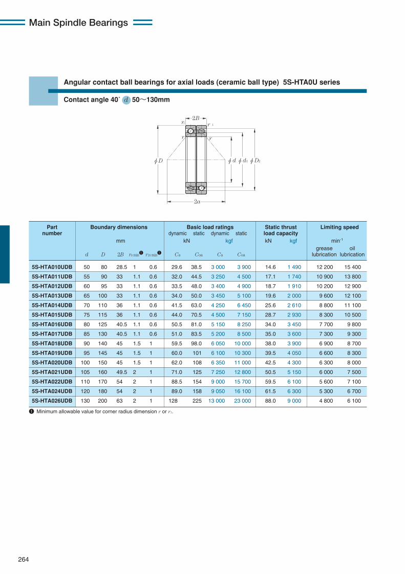
Main Spindle Bearings
264
Angular contact ball bearings for axial loads (ceramic ball type) 5S-HTA0U series
Contact angle 40˚ d 50〜130mm
φD φdφd1φD2
2a
2B
r r
r1 r 1
5S-HTA010UDB 50 80 28.5 1 0.6 29.6 38.5 3 000 3 900 14.6 1 490 12 200 15 400
5S-HTA011UDB 55 90 33 1.1 0.6 32.0 44.5 3 250 4 500 17.1 1 740 10 900 13 800
5S-HTA012UDB 60 95 33 1.1 0.6 33.5 48.0 3 400 4 900 18.7 1 910 10 200 12 900
5S-HTA013UDB 65 100 33 1.1 0.6 34.0 50.0 3 450 5 100 19.6 2 000 9 600 12 100
5S-HTA014UDB 70 110 36 1.1 0.6 41.5 63.0 4 250 6 450 25.6 2 610 8 800 11 100
5S-HTA015UDB 75 115 36 1.1 0.6 44.0 70.5 4 500 7 150 28.7 2 930 8 300 10 500
5S-HTA016UDB 80 125 40.5 1.1 0.6 50.5 81.0 5 150 8 250 34.0 3 450 7 700 9 800
5S-HTA017UDB 85 130 40.5 1.1 0.6 51.0 83.5 5 200 8 500 35.0 3 600 7 300 9 300
5S-HTA018UDB 90 140 45 1.5 1 59.5 98.0 6 050 10 000 38.0 3 900 6 900 8 700
5S-HTA019UDB 95 145 45 1.5 1 60.0 101 6 100 10 300 39.5 4 050 6 600 8 300
5S-HTA020UDB 100 150 45 1.5 1 62.0 108 6 350 11 000 42.5 4 300 6 300 8 000
5S-HTA021UDB 105 160 49.5 2 1 71.0 125 7 250 12 800 50.5 5 150 6 000 7 500
5S-HTA022UDB 110 170 54 2 1 88.5 154 9 000 15 700 59.5 6 100 5 600 7 100
5S-HTA024UDB 120 180 54 2 1 89.0 158 9 050 16 100 61.5 6 300 5 300 6 700
5S-HTA026UDB 130 200 63 2 1 128 225 13 000 23 000 88.0 9 000 4 800 6 100
Part Boundary dimensions Basic load ratings Static thrust Limiting speednumber dynamic static dynamic static load capacity
mm kN kgf kN kgf min-1
grease oild D 2B rs min1 r1s min1 Ca Coa Ca Coa lubrication lubrication
1 Minimum allowable value for corner radius dimension r or r1.
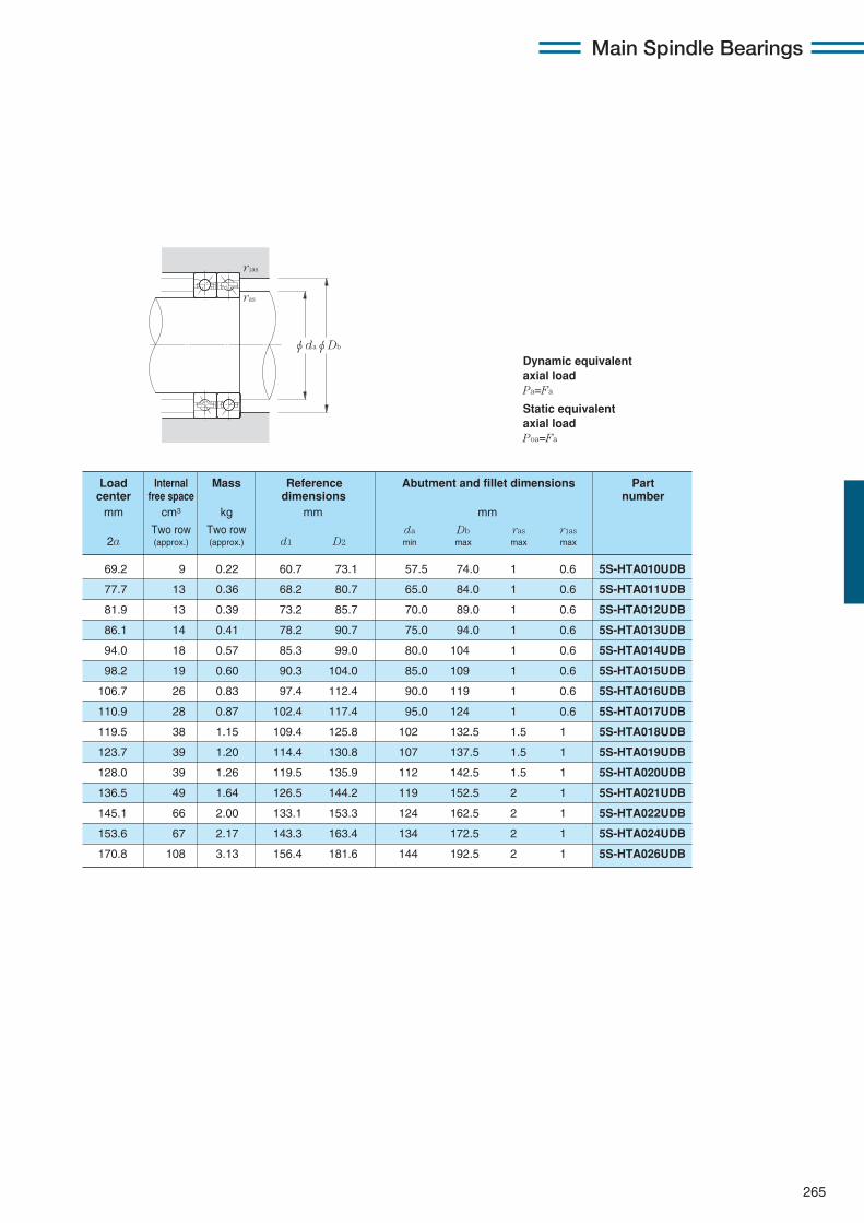
265
Main Spindle Bearings
Dynamic equivalentaxial loadPa=Fa
Static equivalentaxial loadPoa=Fa
φdaφDb
r1as
ras
69.2 9 0.22 60.7 73.1 57.5 74.0 1 0.6 5S-HTA010UDB
77.7 13 0.36 68.2 80.7 65.0 84.0 1 0.6 5S-HTA011UDB
81.9 13 0.39 73.2 85.7 70.0 89.0 1 0.6 5S-HTA012UDB
86.1 14 0.41 78.2 90.7 75.0 94.0 1 0.6 5S-HTA013UDB
94.0 18 0.57 85.3 99.0 80.0 104 1 0.6 5S-HTA014UDB
98.2 19 0.60 90.3 104.0 85.0 109 1 0.6 5S-HTA015UDB
106.7 26 0.83 97.4 112.4 90.0 119 1 0.6 5S-HTA016UDB
110.9 28 0.87 102.4 117.4 95.0 124 1 0.6 5S-HTA017UDB
119.5 38 1.15 109.4 125.8 102 132.5 1.5 1 5S-HTA018UDB
123.7 39 1.20 114.4 130.8 107 137.5 1.5 1 5S-HTA019UDB
128.0 39 1.26 119.5 135.9 112 142.5 1.5 1 5S-HTA020UDB
136.5 49 1.64 126.5 144.2 119 152.5 2 1 5S-HTA021UDB
145.1 66 2.00 133.1 153.3 124 162.5 2 1 5S-HTA022UDB
153.6 67 2.17 143.3 163.4 134 172.5 2 1 5S-HTA024UDB
170.8 108 3.13 156.4 181.6 144 192.5 2 1 5S-HTA026UDB
Load Internal Mass Reference Abutment and fillet dimensions Partcenter free space dimensions number
mm cm3 kg mm mm
Two row Two row da Db ras r1as2a (approx.) (approx.) d1 D2 min max max max

NTN Main Spindle Bearings
NTN Main Spindle Bearings
267
Main Spindle Bearings
12. Tapered Roller Bearings CONTENTS
12. Tapered Roller Bearings ………………………………………………………268〜273q Load calculation ……………………………………………………………………268
w Bearing designation…………………………………………………………………268
e Accuracy………………………………………………………………………………269
r Recommended fit for high-precision tapered roller bearings ………………269
t Dimension tables ……………………………………………………………………270
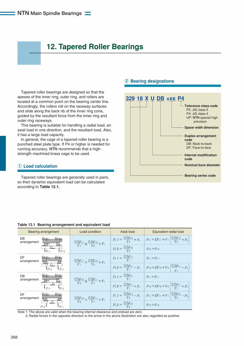
NTN Main Spindle Bearings
268
12. Tapered Roller Bearings
Tapered roller bearings are designed so that theapexes of the inner ring, outer ring, and rollers arelocated at a common point on the bearing center line.Accordingly, the rollers roll on the raceway surfacesand slide along the back rib of the inner ring cone,guided by the resultant force from the inner ring andouter ring raceways.
This bearing is suitable for handling a radial load, anaxial load in one direction, and the resultant load. Also,it has a large load capacity.
In general, the cage of a tapered roller bearing is apunched steel plate type. If P4 or higher is needed forrunning accuracy, NTN recommends that a high-strength machined brass cage to be used.
Tapered roller bearings are generally used in pairs,so their dynamic equivalent load can be calculatedaccording to Table 12.1.
① Load calculation
② Bearing designations
Tolerance class code P5: JIS class 5 P4: JIS class 4 UP: NTN special high precision
Duplex arrangement code DB: Back-to-back DF: Face-to-face
Spacer width dimension
Internal modification code
Nominal bore diameter
Bearing series code
329 18 X U DB +xx P4
Y1
0.5Fr1≦ Y2
0.5Fr2+ Fa
Y1
0.5Fr1> Y2
0.5Fr2+ Fa
Y2
0.5Fr2≦ Y1
0.5Fr1+ Fa
Y2
0.5Fr2> Y1
0.5Fr1+ Fa
Fa1= Y2
0.5Fr2+ Fa
Fa2= Y2
0.5Fr2
Fa1= Y1
0.5Fr1
Fa2= Y1
0.5Fr1- Fa
Fa1= Y1
0.5Fr1
Fa2= Y1
0.5Fr1+ Fa
Fa1= Y2
0.5Fr2- Fa
Fa2= Y2
0.5Fr2
Axial load Equivalent radial loadLoad condition
Y2
0.5Fr2+ FaPr1=XFr1+Y1
Pr2=Fr2
Pr1=Fr1
Y1
0.5Fr1- FaPr2=XFr2+Y2
Pr1=Fr1
Y1
0.5Fr1+ FaPr2=XFr2+Y2
Y2
0.5Fr2- FaPr1=XFr1+Y1
Pr2=Fr2
Bearing arrangement
Fa
Fr1
DB arrangement
DF arrangement
DB arrangement
DF arrangement
Fr2
Fa
Fr2 Fr1
Fr1 Fr2
Fa
Fr2 Fr1
Fa
Brg1 Brg2
Brg2 Brg1
Brg1 Brg2
Brg2 Brg1
Note 1: The above are valid when the bearing internal clearance and preload are zero. 2: Radial forces in the opposite direction to the arrow in the above illustration are also regarded as positive.
Table 12.1 Bearing arrangement and equivalent load
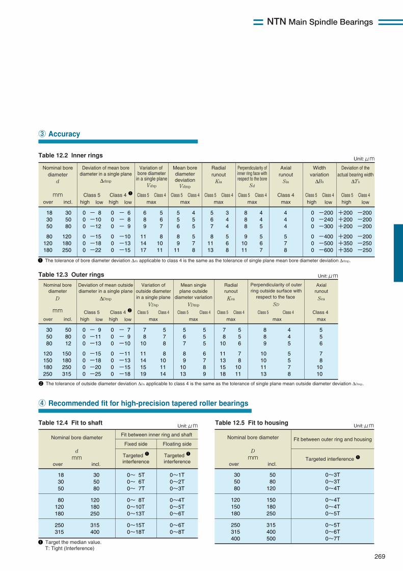
NTN Main Spindle Bearings
269
③ Accuracy
④ Recommended fit for high-precision tapered roller bearings
Nominal bore diameter
d mm
Fit between inner ring and shaft
Fixed side Floating side
Targeted 1 interference
Targeted 1 interference
18 30 50
80 120 180
250 315
30 50 80
120 180 250
315 400
0~ 5T 0~ 6T 0~ 7T
0~ 8T 0~10T 0~13T
0~15T 0~18T
0~1T 0~2T 0~3T
0~4T 0~5T 0~6T
0~6T 0~8T
over incl.
Unit:μm
1 Target the median value. T: Tight (Interference)
Nominal bore diameter
D mm
Fit between outer ring and housing
Targeted interference 1
30 50 80
120 150 180
250 315 400
50 80
120
150 180 250
315 400 500
0~3T 0~3T 0~4T
0~4T 0~4T 0~5T
0~5T 0~6T 0~7T
over incl.
Unit:μm
Nominal bore diameter
d
mm
Deviation of mean bore diameter in a single plane
∆dmp
Class 5 Class 4 1
Variation of bore diameter
in a single plane Vdsp
18 30 50
80 120 180
30 50 80
120 180 250
6 8 9
11 14 17
5 6 7
8 10 11
5 5 6
8 9
11
4 5 5
5 7 8
5 6 7
8 11 13
3 4 4
5 6 8
8 8 8
9 10 11
4 4 5
5 6 7
4 4 4
5 7 8
0 0 0
0 0 0
0 0 0
0 0 0
- 8 -10 -12
-15 -18 -22
- 6 - 8 - 9
-10 -13 -15
0 0 0
0 0 0
-200 -240 -300
-400 -500 -600
+200 +200 +200
+200 +350 +350
-200 -200 -200
-200 -250 -250
over incl.
Axial runout
Sia
high low high low high lowhigh low
Mean bore diameter deviation
Vdmp
Class 5 Class 4max
Class 5 Class 4max
Class 5 Class 4max
Class 5 Class 4max
Class 4max
Class 5 Class 4 Class 5 Class 4
Perpendicularity of inner ring face with respect to the bore
Sd
Radial runout
Kia
Unit:μm
Width variation
∆Bs
Deviation of the actual bearing width
∆Ts
1 The tolerance of bore diameter deviation ∆ds applicable to class 4 is the same as the tolerance of single plane mean bore diameter deviation ∆dmp.
Nominal bore diameter
D
mm
Deviation of mean outside diameter in a single plane
∆Dmp
Class 5 Class 4 2
Variation of outside diameter in a single plane
VDsp
30 50 80
120 150 180 250
50 80 12
150 180 250 315
7 8
10
11 14 15 19
5 7 8
8 10 11 14
5 6 7
8 9
10 13
5 5 5
6 7 8 9
7 8
10
11 13 15 18
5 5 6
7 8
10 11
8 8 9
10 10 11 13
4 4 5
5 5 7 8
5 5 6
7 8
10 10
0 0 0
0 0 0 0
0 0 0
0 0 0 0
- 9 -11 -13
-15 -18 -20 -25
- 7 - 9 -10
-11 -13 -15 -18
over incl.
Axial runout
Sea
high low high low
Mean single plane outside
diameter variation VDmp
Class 5 Class 4 max
Class 5 Class 4 max
Class 5 Class 4 max
Class 5 Class 4 max
Class 4 max
Perpendicularity of outer ring outside surface with
respect to the face SD
Radial runout Kea
Unit:μm
2 The tolerance of outside diameter deviation ∆Ds applicable to class 4 is the same as the tolerance of single plane mean outside diameter deviation ∆Dmp.
Table 12.3 Outer rings
Table 12.2 Inner rings
Table 12.4 Fit to shaft Table 12.5 Fit to housing
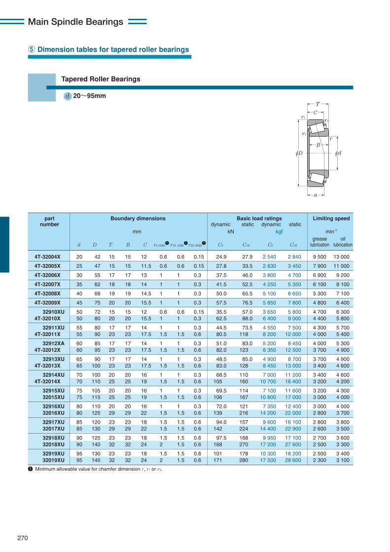
Main Spindle Bearings
270
⑤ Dimension tables for tapered roller bearings
Tapered Roller Bearings
d 20〜95mmT
C
φD φd
a
B
r1r2
r2
r
4T-32004X 20 42 15 15 12 0.6 0.6 0.15 24.9 27.9 2 540 2 840 9 500 13 000
4T-32005X 25 47 15 15 11.5 0.6 0.6 0.15 27.8 33.5 2 830 3 450 7 900 11 000
4T-32006X 30 55 17 17 13 1 1 0.3 37.5 46.0 3 800 4 700 6 900 9 200
4T-32007X 35 62 18 18 14 1 1 0.3 41.5 52.5 4 250 5 350 6 100 8 100
4T-32008X 40 68 19 19 14.5 1 1 0.3 50.0 65.5 5 100 6 650 5 300 7 100
4T-32009X 45 75 20 20 15.5 1 1 0.3 57.5 76.5 5 850 7 800 4 800 6 400
32910XU 50 72 15 15 12 0.6 0.6 0.15 35.5 57.0 3 650 5 800 4 700 6 3004T-32010X 50 80 20 20 15.5 1 1 0.3 62.5 88.0 6 400 9 000 4 400 5 800
32911XU 55 80 17 17 14 1 1 0.3 44.5 73.5 4 550 7 500 4 300 5 7004T-32011X 55 90 23 23 17.5 1.5 1.5 0.6 80.5 118 8 200 12 000 4 000 5 400
32912XA 60 85 17 17 14 1 1 0.3 51.0 83.0 5 200 8 450 4 000 5 3004T-32012X 60 95 23 23 17.5 1.5 1.5 0.6 82.0 123 8 350 12 500 3 700 4 900
32913XU 65 90 17 17 14 1 1 0.3 48.5 85.0 4 900 8 700 3 700 4 9004T-32013X 65 100 23 23 17.5 1.5 1.5 0.6 83.0 128 8 450 13 000 3 400 4 600
32914XU 70 100 20 20 16 1 1 0.3 68.5 110 7 000 11 200 3 400 4 6004T-32014X 70 110 25 25 19 1.5 1.5 0.6 105 160 10 700 16 400 3 200 4 200
32915XU 75 105 20 20 16 1 1 0.3 69.5 114 7 100 11 600 3 200 4 30032015XU 75 115 25 25 19 1.5 1.5 0.6 106 167 10 800 17 000 3 000 4 000
32916XU 80 110 20 20 16 1 1 0.3 72.0 121 7 350 12 400 3 000 4 00032016XU 80 125 29 29 22 1.5 1.5 0.6 139 216 14 200 22 000 2 800 3 700
32917XU 85 120 23 23 18 1.5 1.5 0.6 94.0 157 9 600 16 100 2 800 3 80032017XU 85 130 29 29 22 1.5 1.5 0.6 142 224 14 400 22 900 2 600 3 500
32918XU 90 125 23 23 18 1.5 1.5 0.6 97.5 168 9 950 17 100 2 700 3 60032018XU 90 140 32 32 24 2 1.5 0.6 168 270 17 200 27 600 2 500 3 300
32919XU 95 130 23 23 18 1.5 1.5 0.6 101 178 10 300 18 200 2 500 3 40032019XU 95 145 32 32 24 2 1.5 0.6 171 280 17 500 28 600 2 300 3 100
part Boundary dimensions Basic load ratings Limiting speednumber dynamic static dynamic static
mm kN kgf min-1
grease oild D T B C rs min1 r1s min1r2s min1 Cr Cor Cr Cor lubrication lubrication
1 Minimum allowable value for chamfer dimension r, r1 or r2.
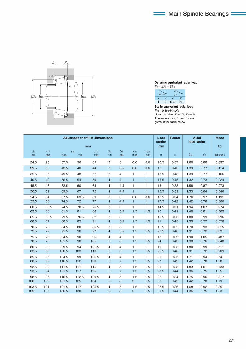
271
Main Spindle Bearings
24.5 25 37.5 36 39 3 3 0.6 0.6 10.5 0.37 1.60 0.88 0.097
29.5 30 42.5 40 44 3 3.5 0.6 0.6 12 0.43 1.39 0.77 0.114
35.5 35 49.5 48 52 3 4 1 1 13.5 0.43 1.39 0.77 0.166
40.5 40 56.5 54 59 4 4 1 1 15.5 0.45 1.32 0.73 0.224
45.5 46 62.5 60 65 4 4.5 1 1 15 0.38 1.58 0.87 0.273
50.5 51 69.5 67 72 4 4.5 1 1 16.5 0.39 1.53 0.84 0.346
54.5 54 67.5 63.5 69 3 3 0.6 0.6 13.5 0.34 1.76 0.97 1.19155.5 56 74.5 72 77 4 4.5 1 1 17.5 0.42 1.42 0.78 0.366
60.5 60.5 74.5 70.5 76.5 3 3 1 1 14.5 0.31 1.94 1.07 0.27463.5 63 81.5 81 86 4 5.5 1.5 1.5 20 0.41 1.48 0.81 0.563
65.5 65.5 79.5 76.5 82 3 3 1 1 15.5 0.33 1.80 0.99 0.29668.5 67 86.5 85 91 4 5.5 1.5 1.5 21 0.43 1.39 0.77 0.576
70.5 70 84.5 80 86.5 3 3 1 1 16.5 0.35 1.70 0.93 0.31573.5 72 91.5 90 97 4 5.5 1.5 1.5 22.5 0.46 1.31 0.72 0.63
75.5 75 94.5 90 96 4 4 1 1 18 0.32 1.90 1.05 0.48778.5 78 101.5 98 105 5 6 1.5 1.5 24 0.43 1.38 0.76 0.848
80.5 80 99.5 94 101.5 4 4 1 1 19 0.33 1.80 0.99 0.51183.5 83 106.5 103 110 5 6 1.5 1.5 25.5 0.46 1.31 0.72 0.909
85.5 85 104.5 99 106.5 4 4 1 1 20 0.35 1.71 0.94 0.5488.5 89 116.5 112 120 6 7 1.5 1.5 27 0.42 1.42 0.78 1.28
93.5 92 111.5 111 115 4 5 1.5 1.5 21 0.33 1.83 1.01 0.73393.5 94 121.5 117 125 6 7 1.5 1.5 28.5 0.44 1.36 0.75 1.35
98.5 96 116.5 112.5 120.5 4 5 1.5 1.5 22 0.34 1.75 0.96 0.817100 100 131.5 125 134 6 8 2 1.5 30 0.42 1.42 0.78 1.79
103.5 101 121.5 117 125.5 4 5 1.5 1.5 23.5 0.36 1.68 0.92 0.851105 105 136.5 130 140 6 8 2 1.5 31.5 0.44 1.36 0.75 1.83
Abutment and fillet dimensions Load Factor Axial Masscenter load factor
mm mm kg
da db Da Db Sa Sb ras r1asmin max max min min min min max max a e Y2 Y0 (approx.)
Sa
r1a
Sb
ra
φda φDbφDa φdb
1 0 0.4 Y2
Fa Fr
X Y X Y
≦eFa Fr>e
Dynamic equivalent radial load Pr=XFr+YFa
Static equivalent radial load Por=0.5Fr+YoFa
Note that when Por<Fr, Por=Fr. The values for e, Y2 and Yo are given in the table below.
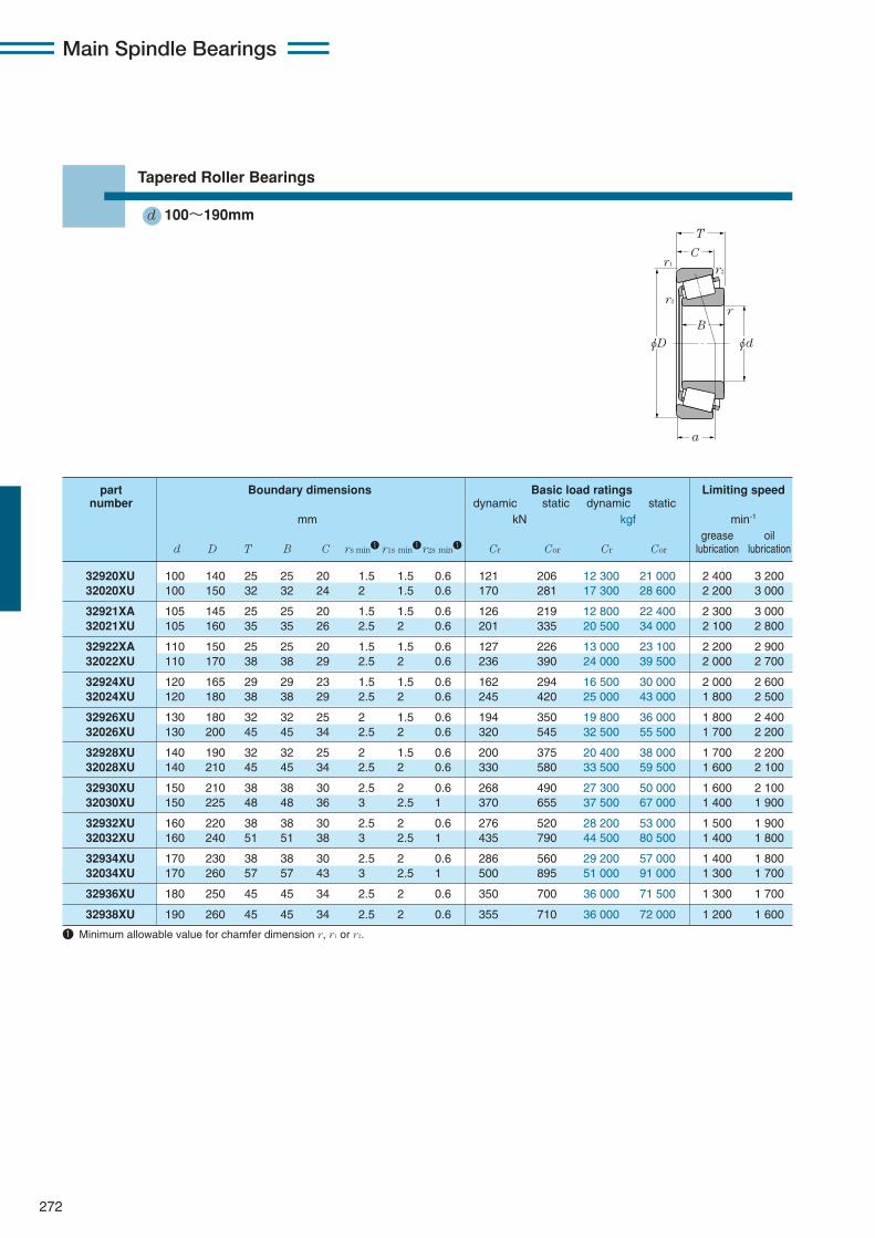
Main Spindle Bearings
272
Tapered Roller Bearings
d 100〜190mmT
C
φD φd
a
B
r1r2
r2
r
32920XU 100 140 25 25 20 1.5 1.5 0.6 121 206 12 300 21 000 2 400 3 20032020XU 100 150 32 32 24 2 1.5 0.6 170 281 17 300 28 600 2 200 3 000
32921XA 105 145 25 25 20 1.5 1.5 0.6 126 219 12 800 22 400 2 300 3 00032021XU 105 160 35 35 26 2.5 2 0.6 201 335 20 500 34 000 2 100 2 800
32922XA 110 150 25 25 20 1.5 1.5 0.6 127 226 13 000 23 100 2 200 2 90032022XU 110 170 38 38 29 2.5 2 0.6 236 390 24 000 39 500 2 000 2 700
32924XU 120 165 29 29 23 1.5 1.5 0.6 162 294 16 500 30 000 2 000 2 60032024XU 120 180 38 38 29 2.5 2 0.6 245 420 25 000 43 000 1 800 2 500
32926XU 130 180 32 32 25 2 1.5 0.6 194 350 19 800 36 000 1 800 2 40032026XU 130 200 45 45 34 2.5 2 0.6 320 545 32 500 55 500 1 700 2 200
32928XU 140 190 32 32 25 2 1.5 0.6 200 375 20 400 38 000 1 700 2 20032028XU 140 210 45 45 34 2.5 2 0.6 330 580 33 500 59 500 1 600 2 100
32930XU 150 210 38 38 30 2.5 2 0.6 268 490 27 300 50 000 1 600 2 10032030XU 150 225 48 48 36 3 2.5 1 370 655 37 500 67 000 1 400 1 900
32932XU 160 220 38 38 30 2.5 2 0.6 276 520 28 200 53 000 1 500 1 90032032XU 160 240 51 51 38 3 2.5 1 435 790 44 500 80 500 1 400 1 800
32934XU 170 230 38 38 30 2.5 2 0.6 286 560 29 200 57 000 1 400 1 80032034XU 170 260 57 57 43 3 2.5 1 500 895 51 000 91 000 1 300 1 700
32936XU 180 250 45 45 34 2.5 2 0.6 350 700 36 000 71 500 1 300 1 700
32938XU 190 260 45 45 34 2.5 2 0.6 355 710 36 000 72 000 1 200 1 600
part Boundary dimensions Basic load ratings Limiting speednumber dynamic static dynamic static
mm kN kgf min-1
grease oild D T B C rs min1 r1s min1r2s min1 Cr Cor Cr Cor lubrication lubrication
1 Minimum allowable value for chamfer dimension r, r1 or r2.
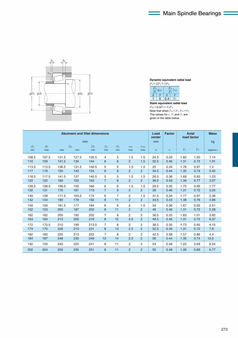
273
Main Spindle Bearings
Sa
r1a
Sb
ra
φda φDbφDa φdb
1 0 0.4 Y2
Fa Fr
X Y X Y
≦eFa Fr>e
Dynamic equivalent radial load Pr=XFr+YFa
Static equivalent radial load Por=0.5Fr+YoFa
Note that when Por<Fr, Por=Fr. The values for e, Y2 and Yo are given in the table below.
108.5 107.5 131.5 127.5 135.5 4 5 1.5 1.5 24.5 0.33 1.82 1.00 1.14110 109 141.5 134 144 6 8 2 1.5 32.5 0.46 1.31 0.72 1.91
113.5 113.5 136.5 131.5 140.5 5 5 1.5 1.5 25 0.34 1.76 0.97 1.2117 116 150 143 154 6 9 2 2 34.5 0.44 1.35 0.74 2.42
118.5 117.5 141.5 137 145.5 5 5 1.5 1.5 26.5 0.36 1.69 0.93 1.23122 122 160 152 163 7 9 2 2 36.5 0.43 1.39 0.77 3.07
128.5 128.5 156.5 150 160 6 6 1.5 1.5 29.5 0.35 1.72 0.95 1.77132 131 170 161 173 7 9 2 2 39 0.46 1.31 0.72 3.25
140 139 171.5 163.5 174 6 7 2 1.5 31.5 0.34 1.77 0.97 2.36142 144 190 178 192 8 11 2 2 43.5 0.43 1.38 0.76 4.96
150 150 181.5 177 184 6 6 2 1.5 34 0.36 1.67 0.92 2.51152 153 200 187 202 8 11 2 2 46 0.46 1.31 0.72 5.28
162 162 200 192 202 7 8 2 2 36.5 0.33 1.83 1.01 3.92164 164 213 200 216 8 12 2.5 2 49.5 0.46 1.31 0.72 6.37
172 170.5 210 199 213.5 7 8 2 2 38.5 0.35 1.73 0.95 4.15174 175 228 213 231 8 13 2.5 2 52.5 0.46 1.31 0.72 7.8
182 183 220 213 222 7 8 2 2 42.5 0.38 1.57 0.86 4.4184 187 248 230 249 10 14 2.5 2 56 0.44 1.35 0.74 10.5
192 193 240 225 241 8 11 2 2 54 0.48 1.25 0.69 6.54
202 204 250 235 251 8 11 2 2 55 0.48 1.26 0.69 6.77
Abutment and fillet dimensions Load Factor Axial Masscenter load factor
mm mm kg
da db Da Db Sa Sb ras r1asmin max max min min min min max max a e Y2 Y0 (approx.)
NTN Ball Screw Support Bearings

NTN Ball Screw Support Bearings
275
Ball Screw Support Bearings
13. Ball Screw Support Bearings CONTENTS
13. Ball Screw Support Bearings …………………………………………………276〜297q Angular contact thrust ball bearings 2A-BST series…………………………276
w Duplex angular contact ball bearings HT series………………………………279
e Needle roller bearings with double-row thrust needle roller bearings AXN series ………279
Needle roller bearings with double-row thrust cylindrical roller bearings ARN series……279
r Bearing designations ………………………………………………………………280
t Bearing precision ……………………………………………………………………281
y Basic preload and axial rigidity……………………………………………………284
u Shaft and housing fit…………………………………………………………………285
i Applications……………………………………………………………………………285
o Starting torque of BST type ………………………………………………………286
!0 Recommended lubrication specifications ……………………………………287
!1 Dimension tablesAngular contact thrust ball bearingsBST and BST LXL series ………………………………………………………2882A-BST and 2A-BST LXL series ………………………………………………290
Duplex angular contact ball bearings HT series ……………………………294Needle roller bearings with double-row thrust needle roller bearingsAXN , ARN series …………………………………………………………………296

NTN Ball Screw Support Bearings
276
13. Ball Screw Support Bearings
NTN ballscrew bearings are optimized to support a ballscrew.These bearings are categorized as shown in Table 13.1.
The 2A-BST type incorporates the maximum possiblenumber of small balls (compared with those of astandard bearing), has thicker inner and outer rings,and a larger contact angle of 60˚. Thus, this type ofbearing boasts greater axial rigidity. Additionally, sinceballs are used as the rolling elements, the startingtorque of a angular contact thrust ball bearing is lessthan that of a roller bearing.Open (BST and 2A-BST type) and light-contact seals
(BST LXL and 2A-BST LXL type) are available andmolded resin cages are standard.Side faces of BST type bearings are flush-ground to
provide the same face height difference for both thefront and back faces. As a result, bearings of the samepart number can be freely combined into DB, DBT,DTBT configurations as illustrated in Fig. 13.2, and theadjustment for a relevant preload is no longernecessary.Every single bearing is machined to the same face
height so that when any arrangement is installed on aballscrew the unit has optimal preload. For thisreason, no time-consuming preload adjustment(adjustment with shims or tightening and looseningwhile measuring the starting torque) is necessary.
■Features 2A-BST-1B (LXL/L588)1. Unique heat treatment greatly improves resistanceagainst rolling contact fatigue, leading to longerservice life (approximately two times that of theconventional type).
2. Both sides are sealed to enhance contaminationresistance and to preserve the grease. (Light-contact seal type)
① Angular contact thrust ball bearings BST-1B (LXL/L588), 2A-BST-1B (LXL/L588) series
Type code Notes Bore diameter
BST 2A-BST
BST LXL/L588 2A-BST LXL/L588
Open type thrust angular contact ball bearing with 60˚ contact angle, generally used with grease lubrication
Grease-lubricated sealed angular contact ball bearing with 60˚ contact angle
Duplex angular contact ball bearing with 30˚ contact angle, generally used with grease lubrication
Needle roller bearing with double-direction thrust needle roller bearing, generally used with oil lubrication
Needle roller bearing with double-direction thrust cylindrical roller bearing, generally used with oil lubrication
HT
AXN
ARN
φ17~φ60
φ17~φ60
φ6~φ40
φ20~φ50
φ20~φ70
Open type 2A-BST type
Light-contact sealed type 2A-BST LXL type
DB DBT DTBT
Fig. 13.1
Fig. 13.2 Bearing arrangement
Table 13.1 Bearing types
3. Special long-life grease is used. (Light-contact sealtype)
4. The combination of a unique heat treatment andspecial grease reduces fretting (by 80% or more forsliding mode, 90% or more for rolling mode,compared to the conventional type). (Light-contactseal type)
5. Pre-grease bearings eliminate the need for furthergrease packing and allow easier handling. (Light-contact seal type)
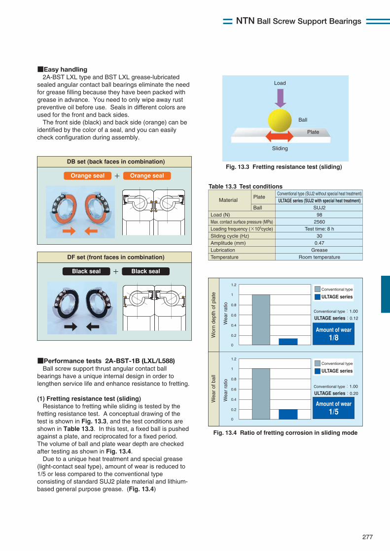
NTN Ball Screw Support Bearings
277
■Easy handling2A-BST LXL type and BST LXL grease-lubricated
sealed angular contact ball bearings eliminate the needfor grease filling because they have been packed withgrease in advance. You need to only wipe away rustpreventive oil before use. Seals in different colors areused for the front and back sides.The front side (black) and back side (orange) can be
identified by the color of a seal, and you can easilycheck configuration during assembly.
■Performance tests 2A-BST-1B (LXL/L588)Ball screw support thrust angular contact ball
bearings have a unique internal design in order tolengthen service life and enhance resistance to fretting.
(1) Fretting resistance test (sliding)Resistance to fretting while sliding is tested by the
fretting resistance test. A conceptual drawing of thetest is shown in Fig. 13.3, and the test conditions areshown in Table 13.3. In this test, a fixed ball is pushedagainst a plate, and reciprocated for a fixed period.The volume of ball and plate wear depth are checkedafter testing as shown in Fig. 13.4.Due to a unique heat treatment and special grease
(light-contact seal type), amount of wear is reduced to1/5 or less compared to the conventional typeconsisting of standard SUJ2 plate material and lithium-based general purpose grease. (Fig. 13.4)
DF set (front faces in combination)
+ Black seal Black seal
DB set (back faces in combination)
+ Orange seal Orange seal
Load (N) Max. contact surface pressure (MPa) Loading frequency (×105cycle) Sliding cycle (Hz) Amplitude (mm) Lubrication Temperature
Conventional type (SUJ2 without special heat treatment) ULTAGE series (SUJ2 with special heat treatment)
SUJ2 98
2560 Test time: 8 h
30 0.47
Grease Room temperature
MaterialPlate
Ball
1.2
1
0.8
0.6
0.4
0.2
0
Conventional type
ULTAGE series
Conventional type:1.00
Amount of wear 1/8
1.2
1
0.8
0.6
0.4
0.2
0
Conventional type
ULTAGE series
ULTAGE series:0.12
Conventional type:1.00
ULTAGE series:0.20
Fig. 13.3 Fretting resistance test (sliding)
Table 13.3 Test conditions
Load
Sliding
Ball
Plate
Fig. 13.4 Ratio of fretting corrosion in sliding mode
Wor
n de
pth
of p
late
Wea
r of
bal
l
Wea
r ra
tioW
ear
ratio
Amount of wear 1/5
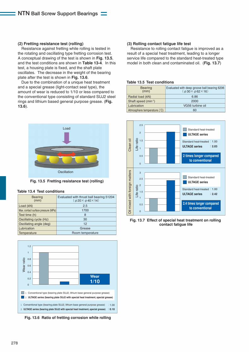
NTN Ball Screw Support Bearings
278
(2) Fretting resistance test (rolling)Resistance against fretting while rolling is tested in
the rotating and oscillating type fretting corrosion test.A conceptual drawing of the test is shown in Fig. 13.5,and the test conditions are shown in Table 13-4. In thistest, a housing plate is fixed, and the shaft plateoscillates. The decrease in the weight of the bearingplate after the test is shown in Fig. 13.6.Due to the combination of a unique heat treatment
and a special grease (light-contact seal type), theamount of wear is reduced to 1/10 or less compared tothe conventional type consisting of standard SUJ2 steelrings and lithium based general purpose grease. (Fig.13.6).
(3) Rolling contact fatigue life testResistance to rolling contact fatigue is improved as a
result of a special heat treatment, leading to a longerservice life compared to the standard heat-treated typemodel in both clean and contaminated oil. (Fig. 13.7)
Table 13.4 Test conditions
Fig. 13.6 Ratio of fretting corrosion while rolling
Load
Oscillation
Load (kN) Max. contact surface pressure (MPa) Test time (h) Oscillating cycle (Hz) Oscillating angle (deg) Lubrication Temperature
2.5 1700
8 30 12
Grease Room temperature
Bearing (mm)
Evaluated with thrust ball bearing 51204 (φ20×φ40×14)
1 Conventional type (bearing plate SUJ2, lithium base general purpose grease)
2 ULTAGE series (bearing plate SUJ2 with special heat treatment, special grease)
1 Conventional type (bearing plate SUJ2, lithium base general purpose grease)
2 ULTAGE series (bearing plate SUJ2 with special heat treatment, special grease)
:1.00
:0.10
1.2
1
0.8
0.6
0.4
0.2
0
Wear 1/10
Fig. 13.5 Fretting resistance test (rolling)
Wea
r ra
tio
Table 13.5 Test conditions
Fig. 13.7 Effect of special heat treatment on rolling contact fatigue life
Radial load (kN) Shaft speed (min-1) Lubrication Atmosphere temperature (˚C)
6.86 2000
VG56 turbine oil 60
Bearing (mm)
Evaluated with deep groove ball bearing 6206 (φ30×φ62×16)
2.5
2
1.5
1
0.5
0
Standard heat-treated
:1.00
:2.03
2.5
3
2
1.5
1
0.5
0
Standard heat-treated
ULTAGE series
:1.00
:2.42
ULTAGE series
Standard heat-treated
Standard heat-treated
ULTAGE series
ULTAGE series
2 times longer compared to conventional
2.4 times longer compared to conventional
Cle
an o
ilO
il m
ixed
with
fore
ign
mat
ters
Life
rat
ioLi
fe r
atio
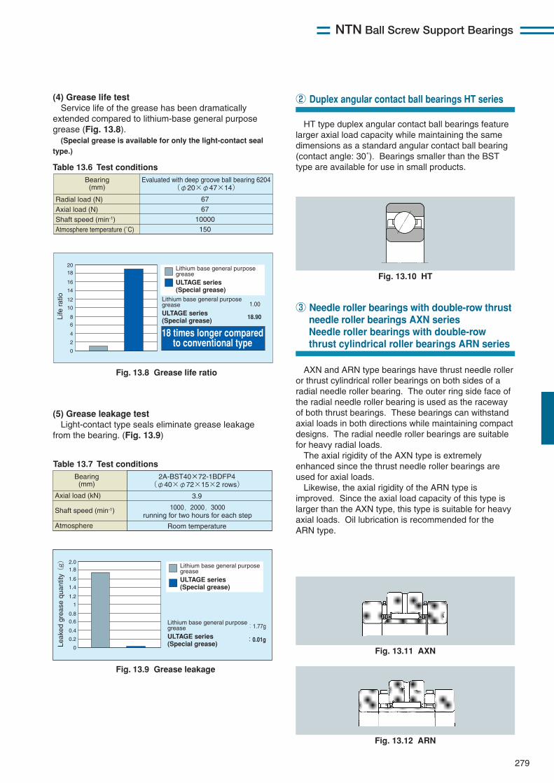
AXN and ARN type bearings have thrust needle rolleror thrust cylindrical roller bearings on both sides of aradial needle roller bearing. The outer ring side face ofthe radial needle roller bearing is used as the racewayof both thrust bearings. These bearings can withstandaxial loads in both directions while maintaining compactdesigns. The radial needle roller bearings are suitablefor heavy radial loads.The axial rigidity of the AXN type is extremely
enhanced since the thrust needle roller bearings areused for axial loads.Likewise, the axial rigidity of the ARN type is
improved. Since the axial load capacity of this type islarger than the AXN type, this type is suitable for heavyaxial loads. Oil lubrication is recommended for theARN type.
HT type duplex angular contact ball bearings featurelarger axial load capacity while maintaining the samedimensions as a standard angular contact ball bearing(contact angle: 30˚). Bearings smaller than the BSTtype are available for use in small products.
NTN Ball Screw Support Bearings
279
(4) Grease life testService life of the grease has been dramatically
extended compared to lithium-base general purposegrease (Fig. 13.8).(Special grease is available for only the light-contact seal
type.)
Table 13.6 Test conditions
Fig. 13.8 Grease life ratio
Radial load (N) Axial load (N) Shaft speed (min-1) Atmosphere temperature (˚C)
67 67
10000 150
Bearing (mm)
Evaluated with deep groove ball bearing 6204 (φ20×φ47×14)
2018
16
14
12
10
6
8
4
2
0
Life
rat
io
Lithium base general purpose greaseULTAGE series (Special grease)
Lithium base general purpose greaseULTAGE series (Special grease)
1.00
18.90
18 times longer compared to conventional type
(5) Grease leakage testLight-contact type seals eliminate grease leakage
from the bearing. (Fig. 13.9)
Table 13.7 Test conditions
Fig. 13.9 Grease leakage
Axial load (kN) Shaft speed (min-1)
Atmosphere
3.9
Room temperature
Bearing (mm)
2A-BST40×72-1BDFP4 (φ40×φ72×15×2 rows)
1000,2000,3000
running for two hours for each step
2.01.8
1.6
1.4
1.2
1
0.6
0.8
0.4
0.2
0 Lea
ked
grea
se q
uant
ity(g)
:1.77g
:0.01g
Lithium base general purpose greaseULTAGE series (Special grease)
Lithium base general purpose greaseULTAGE series (Special grease)
Fig. 13.10 HT
② Duplex angular contact ball bearings HT series
③ Needle roller bearings with double-row thrustneedle roller bearings AXN seriesNeedle roller bearings with double-rowthrust cylindrical roller bearings ARN series
Fig. 13.11 AXN
Fig. 13.12 ARN
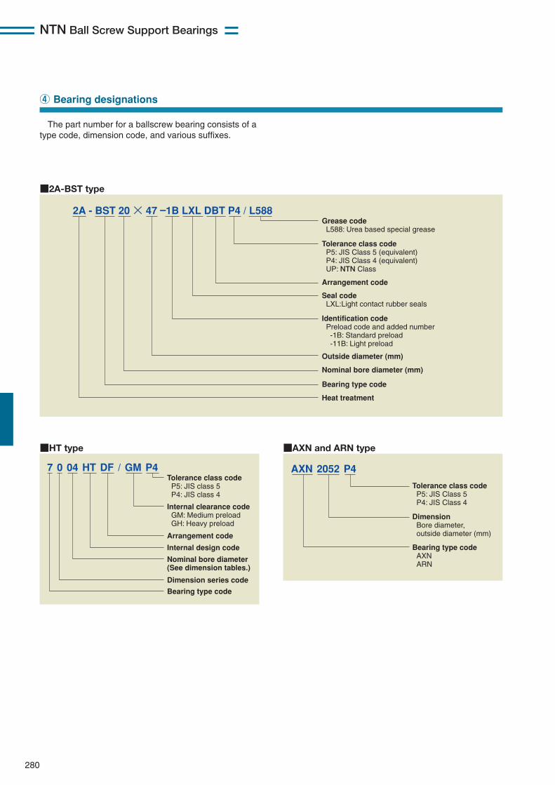
The part number for a ballscrew bearing consists of atype code, dimension code, and various suffixes.
NTN Ball Screw Support Bearings
280
④ Bearing designations
Grease code L588: Urea based special grease Tolerance class code P5: JIS Class 5 (equivalent) P4: JIS Class 4 (equivalent) UP: NTN Class Seal code LXL:Light contact rubber seals
Arrangement code
Identification code Preload code and added number -1B: Standard preload -11B: Light preload
Outside diameter (mm)
Nominal bore diameter (mm)
Bearing type code
Heat treatment
2A - BST 20 × 47 –1B LXL DBT P4 / L588
■2A-BST type
Tolerance class code P5: JIS Class 5 P4: JIS Class 4
Dimension Bore diameter, outside diameter (mm)
Bearing type code AXN ARN
AXN 2052 P4
■AXN and ARN type
Tolerance class code P5: JIS class 5 P4: JIS class 4
Internal clearance code GM: Medium preload GH: Heavy preload
Arrangement code
Internal design code
Nominal bore diameter (See dimension tables.)
Dimension series code
Bearing type code
7 0 04 HT DF / GM P4
■HT type
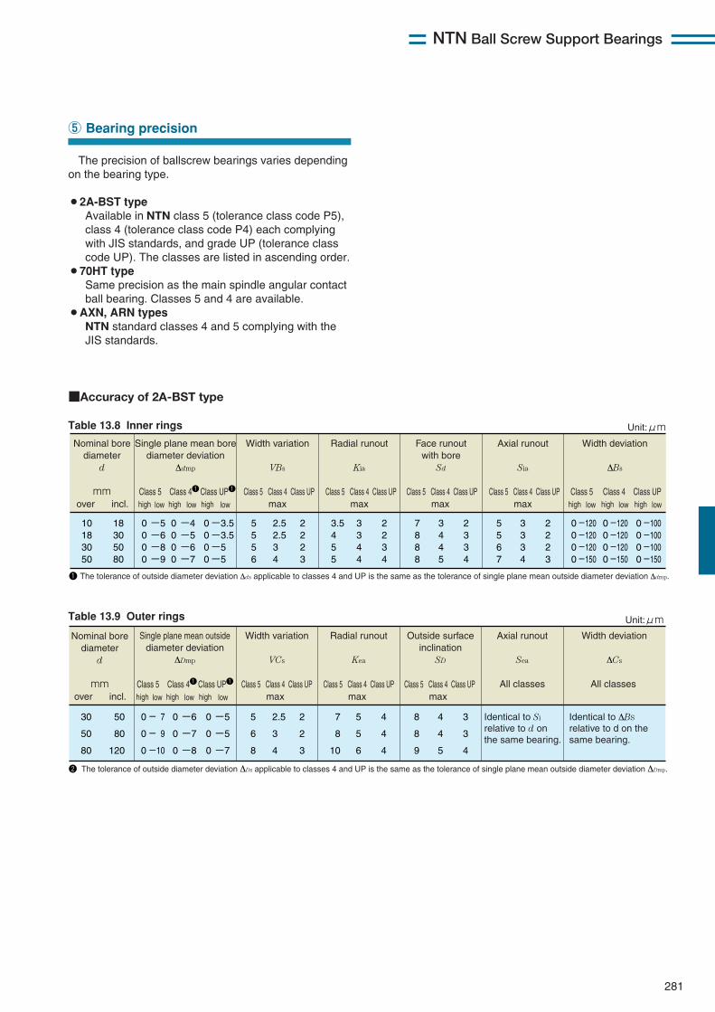
Single plane mean outside diameter deviation
ΔDmp
30
50
80
50
80
120
0
0
0
5
6
8
2.5
3
4
2
2
3
7
8
10
5
5
6
4
4
4
8
8
9
4
4
5
3
3
4
Identical to Si relative to d on the same bearing.
Identical to ΔBS relative to d on the same bearing.
- 7
- 9
-10
0
0
0
-6
-7
-8
0
0
0
-5
-5
-7
Axial runout
Sea
Width deviation
ΔCs
All classesAll classes
Outside surface inclination
SD
Radial runout
Kea
Width variation
VCs
Nominal bore diameter
d mm Class 5 Class 41Class UP1 Class 5 Class 4 Class UP
over incl. high low high low high low maxClass 5 Class 4 Class UP
maxClass 5 Class 4 Class UP
max
Unit:μm
2 The tolerance of outside diameter deviation ΔDs applicable to classes 4 and UP is the same as the tolerance of single plane mean outside diameter deviation ΔDmp.
NTN Ball Screw Support Bearings
281
The precision of ballscrew bearings varies dependingon the bearing type.
¡2A-BST typeAvailable in NTN class 5 (tolerance class code P5),class 4 (tolerance class code P4) each complyingwith JIS standards, and grade UP (tolerance classcode UP). The classes are listed in ascending order.
¡70HT typeSame precision as the main spindle angular contactball bearing. Classes 5 and 4 are available.
¡AXN, ARN typesNTN standard classes 4 and 5 complying with theJIS standards.
⑤ Bearing precision
■Accuracy of 2A-BST type
Table 13.8 Inner rings
Nominal bore diameter
d mm
Single plane mean bore diameter deviation
Δdmp
Class 5 Class 41Class UP1 Class 5 Class 4 Class UP
10 18 30 50
18 30 50 80
0 0 0 0
5 5 5 6
2.5 2.5 3 4
2 2 2 3
3.5 4 5 5
3 3 4 4
2 2 3 4
7 8 8 8
3 4 4 5
2 3 3 4
5 5 6 7
3 3 3 4
2 2 2 3
-5 -6 -8 -9
0 0 0 0
-3.5 -3.5 -5 -5
0 0 0 0
-4 -5 -6 -7
over incl.
Axial runout
Sia
Width deviation
ΔBs
high low high low high low high low high low high low
0 0 0 0
-120 -120 -120 -150
0 0 0 0
-120 -120 -120 -150
0 0 0 0
-100 -100 -100 -150
maxClass 5 Class 4 Class UP
maxClass 5 Class 4 Class UP
maxClass 5 Class 5Class 4 Class 4Class UP Class UP
max
Face runout with bore
Sd
Radial runout
Kia
Unit:μm
Width variation
VBs
1 The tolerance of outside diameter deviation Δds applicable to classes 4 and UP is the same as the tolerance of single plane mean outside diameter deviation Δdmp.
Table 13.9 Outer rings
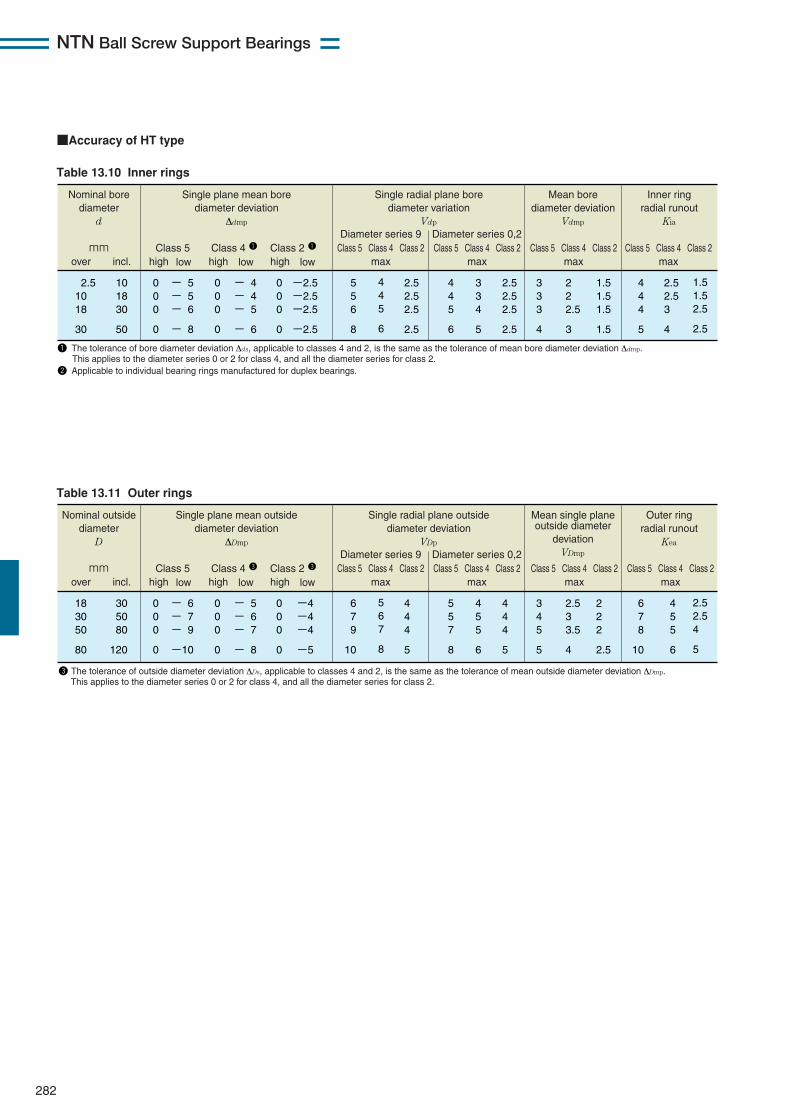
NTN Ball Screw Support Bearings
282
Table 13.10 Inner rings
Nominal bore diameter
d mm
Single plane mean bore diameter deviation
Δdmp
Class 5 Class 4 1 Class 2 1
Single radial plane bore diameter variation
Vdp
Diameter series 9
2.5 10 18
30
10 18 30
50
0 0 0
0
- 5 - 5 - 6
- 8
0 0 0
0
- 4 - 4 - 5
- 6
0 0 0
0
5 5 6
8
4 4 5
6
2.5 2.5 2.5
2.5
-2.5 -2.5 -2.5
-2.5
over incl. high low
A
high low high low
4 4 5
6
3 3 4
5
2.5 2.5 2.5
2.5
3 3 3
4
2 2 2.5
3
1.5 1.5 1.5
1.5
4 4 4
5
2.5 2.5 3
4
1.5 1.5 2.5
2.5
Diameter series 0,2
Mean bore diameter deviation
Vdmp
Inner ring radial runout
Kia
Class 5 Class 4 Class 2max
Class 5 Class 4 Class 2max
Class 5 Class 4 Class 2max
Class 5 Class 4 Class 2max
1 The tolerance of bore diameter deviation Δds, applicable to classes 4 and 2, is the same as the tolerance of mean bore diameter deviation Δdmp. This applies to the diameter series 0 or 2 for class 4, and all the diameter series for class 2. 2 Applicable to individual bearing rings manufactured for duplex bearings.
Table 13.11 Outer rings
Nominal outside diameter
D mm
Single plane mean outside diameter deviation
ΔDmp
Class 5 Class 4 3 Class 2 3
Single radial plane outside diameter deviation
VDp
Diameter series 9
18 30 50
80
30 50 80
120
0 0 0
0
- 6 - 7 - 9
-10
0 0 0
0
- 5 - 6 - 7
- 8
0 0 0
0
6 7 9
10
5 6 7
8
4 4 4
5
-4 -4 -4
-5
over incl. high low
A
high low high low
5 5 7
8
4 5 5
6
4 4 4
5
3 4 5
5
2.5 3 3.5
4
2 2 2
2.5
6 7 8
10
4 5 5
6
2.5 2.5 4
5
Diameter series 0,2
Mean single plane outside diameter
deviation VDmp
Outer ring radial runout
Kea
Class 5 Class 4 Class 2max
Class 5 Class 4 Class 2max
Class 5 Class 4 Class 2max
Class 5 Class 4 Class 2max
3 The tolerance of outside diameter deviation ΔDs, applicable to classes 4 and 2, is the same as the tolerance of mean outside diameter deviation ΔDmp. This applies to the diameter series 0 or 2 for class 4, and all the diameter series for class 2.
■Accuracy of HT type
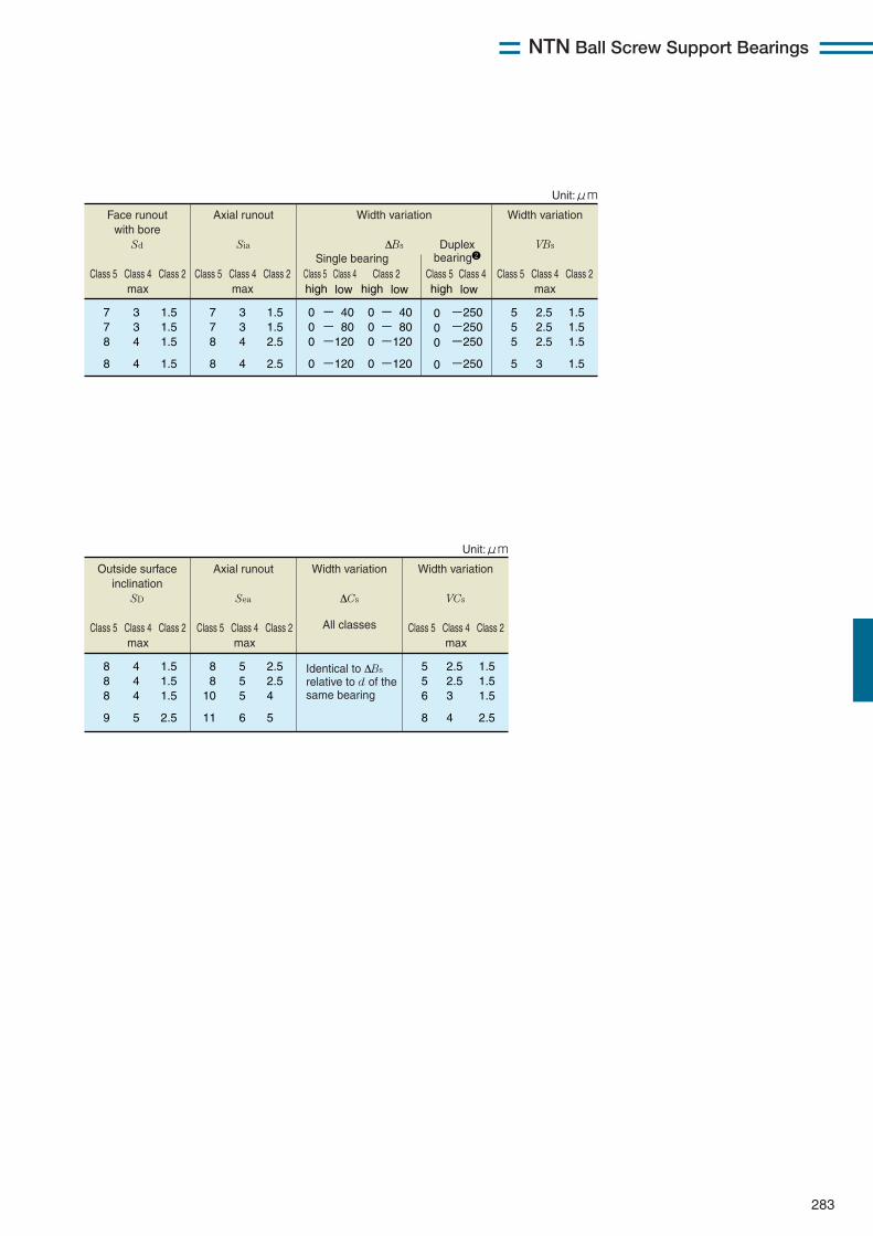
NTN Ball Screw Support Bearings
283
Axial runout
Sia
Width variation
ΔBs
Width variation
VBs
7 7 8
8
1.5 1.5 2.5
2.5
3 3 4
4
5 5 5
5
1.5 1.5 1.5
1.5
2.5 2.5 2.5
3
0 0 0
0
- 40 - 80 -120
-120
0 0 0
0
- 40 - 80 -120
-120
0 0 0
0
-250 -250 -250
-250
high low high low
Class 5 Class 4 Class 2max
Class 5 Class 5Class 4 Class 4Class 2 Class 2max
Class 5 Class 4 Class 2max
Single bearingDuplex
bearing2
high lowClass 5 Class 4
Face runout with bore
Sd
7 7 8
8
1.5 1.5 1.5
1.5
3 3 4
4
Unit:μm
This applies to the diameter series 0 or 2 for class 4, and all the diameter series for class 2. 2
Axial runout
Sea
Width variation
ΔCs
All classes
Width variation
VCs
8 8
10
11
2.5 2.5 4
5
5 5 5
6
5 5 6
8
1.5 1.5 1.5
2.5
2.5 2.5 3
4
Identical to ΔBs relative to d of the same bearing
h
Class 5 Class 4 Class 2max
Class 5 Class 4 Class 2max
Class 5 Class 4 Class 2max
Outside surface inclination
SD
8 8 8
9
1.5 1.5 1.5
2.5
4 4 4
5
Unit:μm
This applies to the diameter series 0 or 2 for class 4, and all the diameter series for class 2.
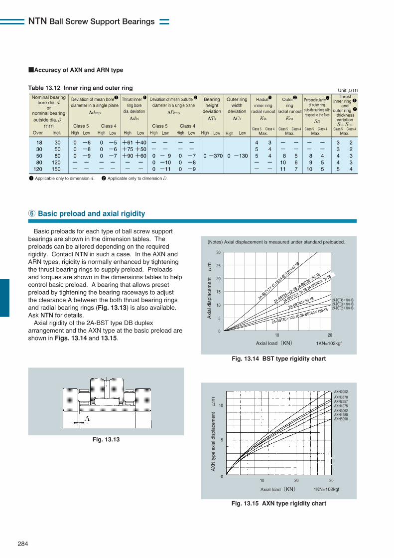
NTN Ball Screw Support Bearings
284
Nominal bearing bore dia. d
or nominal bearing outside dia. D mm
Deviation of mean bore1 diameter in a single plane
Δdmp
Thrust inner 1 ring bore
dia. deviation
Δdis
Class 5 Class 4
30 50 80
120 150
18 30 50 80
120
+61 +75 +90 - -
+40 +50 +60 - -
Over Incl. High Low
Radial1 inner ring
radial runout Kia
4 5 5 - -
3 4 4 - -
Max.
Bearing height
deviation ΔTs
0
-370
High Low
Outer ring width
deviation
ΔCs
0
-130
High Low
0 0 0 - -
-5 -6 -7 - -
High Low
0 0 0 - -
-6 -8 -9 - -
High Low
Class 5 Class 4Class 5 Class 4
Max.Class 5 Class 4
Max.Class 5 Class 4
Max.Class 5 Class 4
2 2 3 3 4
3 3 4 4 5
Outer2 ring
radial runout Kea
- - 8 10 11
- - 5 6 7
Perpendicularity2 of outer ring
outside surface with respect to the face
SD
Thrust inner ring 1
and outer ring 2
thickness variation Sia, Sea
- - 8 9 10
- - 4 5 5
- - 0 0 0
- - -7 -8 -9
High Low
- - 0 0 0
- - - 9 -10 -11
High Low
Deviation of mean outside 2 diameter in a single plane
ΔDmp
Unit:μm
1 Applicable only to dimension d. 2 Applicable only to dimension D.
Table 13.12 Inner ring and outer ring
■Accuracy of AXN and ARN type
Basic preloads for each type of ball screw supportbearings are shown in the dimension tables. Thepreloads can be altered depending on the requiredrigidity. Contact NTN in such a case. In the AXN andARN types, rigidity is normally enhanced by tighteningthe thrust bearing rings to supply preload. Preloadsand torques are shown in the dimensions tables to helpcontrol basic preload. A bearing that allows presetpreload by tightening the bearing raceways to adjustthe clearance A between the both thrust bearing ringsand radial bearing rings (Fig. 13.13) is also available.Ask NTN for details.Axial rigidity of the 2A-BST type DB duplex
arrangement and the AXN type at the basic preload areshown in Figs. 13.14 and 13.15.
⑥ Basic preload and axial rigidity
(Notes) Axial displacement is measured under standard preloaded.
Axial load(KN) 1KN=102kgf
2A-BST45×100-1B,2A-BST50×100-1B,2A-BST55×100-1B
30
25
20
15
10
5
010 20
Axi
al d
ispl
acem
ent μ
m
2A-BST17
×47-1B
,2A-BST20
×47-1B
2A-BST25×62-1B,2A-BST30×
62-1B
2A-BST35×72-1B,2A-BST40×72-1B
2A-BST40×90-1B
2A-BST55×120-1B,2A-BST60×120-1B
Fig. 13.14 BST type rigidity chart
Axial load(KN) 1KN=102kgf
AXN2052AXN3570AXN2557AXN4075AXN3062AXN4580AXN5090
010 20 30
5
10
AX
N ty
pe a
xial
dis
plac
emen
t μ
m
Fig. 13.15 AXN type rigidity chart
Fig. 13.13

NTN Ball Screw Support Bearings
The BST type is mainly installed on ball screws ofmachine tool feed systems, and two to four rowarrangements are used in many cases. This type ispopular because greased sealed angular contact ballbearings are easy to handle. The back-to-back duplexarrangement is commonly used because it allows
285
Recommended fit and tolerances of shaft andhousing shoulder squareness are shown in Figs. 13.13and 13.14.
⑦ Shaft and housing fits
⑧ Applications
Table 13.13 Shaft and housing fits Table 13.14 Tolerance of shoulder squareness
Type codeFit
Shaft outside diameter Housing
h5BST HT H6
j5AXN ARN J6
Diameter classification mm
Type code
AXN,ARNBST
30 80
120 180
4 4 5 -
4 5 6 7
HT
4 4 - -
- 30 80
120
over incl.
Unit:μm
Fig. 13.16 Fig. 13.17
acquisition of the specified preload by tightening theinner ring. The face-to-face duplex arrangement maybe used if more precise alignment is required. It is notcommonly used for machine tools. Examples ofbearing arrangement are shown in Figs. 13.16 and13.17.
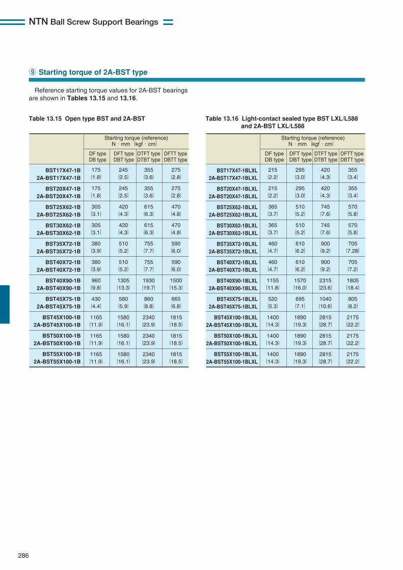
NTN Ball Screw Support Bearings
286
Reference starting torque values for 2A-BST bearingsare shown in Tables 13.15 and 13.16.
⑨ Starting torque of 2A-BST type
Table 13.15 Open type BST and 2A-BST Table 13.16 Light-contact sealed type BST LXL/L588and 2A-BST LXL/L588
Starting torque (reference) N・mm{kgf・cm}
DF type DB type
DFT type DBT type
DTFT type DTBT type
DFTT type DBTT type
BST17X47-1B 2A-BST17X47-1B
BST20X47-1B 2A-BST20X47-1B
BST25X62-1B 2A-BST25X62-1B
BST30X62-1B
2A-BST30X62-1B
BST35X72-1B
2A-BST35X72-1B
BST40X72-1B
2A-BST40X72-1B
BST40X90-1B
2A-BST40X90-1B
BST45X75-1B
2A-BST45X75-1B
BST45X100-1B
2A-BST45X100-1B
BST50X100-1B
2A-BST50X100-1B
BST55X100-1B
2A-BST55X100-1B
175 {1.8}
245 {2.5}
175 {1.8}
245 {2.5}
305 {3.1}
420 {4.3}
305 {3.1}
420 {4.3}
380 {3.9}
510 {5.2}
380 {3.9}
510 {5.2}
960 {9.8}
1305 {13.3}
430 {4.4}
580 {5.9}
1165 {11.9}
1580 {16.1}
1165 {11.9}
1580 {16.1}
1165 {11.9}
1580 {16.1}
355 {3.6}
275 {2.8}
355 {3.6}
275 {2.8}
615 {6.3}
470 {4.8}
615 {6.3}
470 {4.8}
755 {7.7}
590 {6.0}
755 {7.7}
590 {6.0}
1930 {19.7}
1500 {15.3}
860 {8.8}
665 {6.8}
2340 {23.9}
1815 {18.5}
2340 {23.9}
1815 {18.5}
2340 {23.9}
1815 {18.5}
Starting torque (reference) N・mm{kgf・cm}
DF type DB type
DFT type DBT type
DTFT type DTBT type
DFTT type DBTT type
BST17X47-1BLXL
2A-BST17X47-1BLXL
BST20X47-1BLXL
2A-BST20X47-1BLXL
BST25X62-1BLXL
2A-BST25X62-1BLXL
BST30X62-1BLXL
2A-BST30X62-1BLXL
BST35X72-1BLXL
2A-BST35X72-1BLXL
BST40X72-1BLXL
2A-BST40X72-1BLXL
BST40X90-1BLXL
2A-BST40X90-1BLXL
BST45X75-1BLXL
2A-BST45X75-1BLXL
BST45X100-1BLXL
2A-BST45X100-1BLXL
BST50X100-1BLXL
2A-BST50X100-1BLXL
BST55X100-1BLXL
2A-BST55X100-1BLXL
215 {2.2}
295 {3.0}
215 {2.2}
295 {3.0}
365 {3.7}
510 {5.2}
365 {3.7}
510 {5.2}
460 {4.7}
610 {6.2}
460 {4.7}
610 {6.2}
1155 {11.8}
1570 {16.0}
520 {5.3}
695 {7.1}
1400 {14.3}
1890 {19.3}
1400 {14.3}
1890 {19.3}
1400 {14.3}
1890 {19.3}
420 {4.3}
355 {3.4}
420 {4.3}
355 {3.4}
745 {7.6}
570 {5.8}
745 {7.6}
570 {5.8}
900 {9.2}
705 {7.28}
900 {9.2}
705 {7.2}
2315 {23.6}
1805 {18.4}
1040 {10.6}
805 {8.2}
2815 {28.7}
2175 {22.2}
2815 {28.7}
2175 {22.2}
2815 {28.7}
2175 {22.2}
NTN Ball Screw Support Bearings
287
BST and HT ball screw support angular contact ballbearings are generally lubricated with grease. (BSTLXL bearings with light-contact seals are packed withgrease.) AXN and ARN bearings are generallylubricated with circulated oil.
■Grease lubrication¡Recommended type of grease Lithium-mineral oil base general purpose grease ofwhich base oil viscosity is high (for example, AlvaniaGrease S2, Shell).
¡Recommended grease fill25% of the capacity shown in the dimensions tables
¡Recommended grease filling methodRefer to "6. Handling of Bearings, q Rinsing ofbearings and grease filling" in the Technical Datasection.
!0 Recommended lubrication specifications
■Oil lubrication¡Recommended type of oilHydraulic oils or other industrial oils used forlubrication of sliding surfaces with viscosity gradeISO VG 68 or higher are recommended.
¡Oil quantityRecommended oil quantity depends on thelubricating method. As a general guideline, the oilflow rate should be 5 to 10 cm3/min.
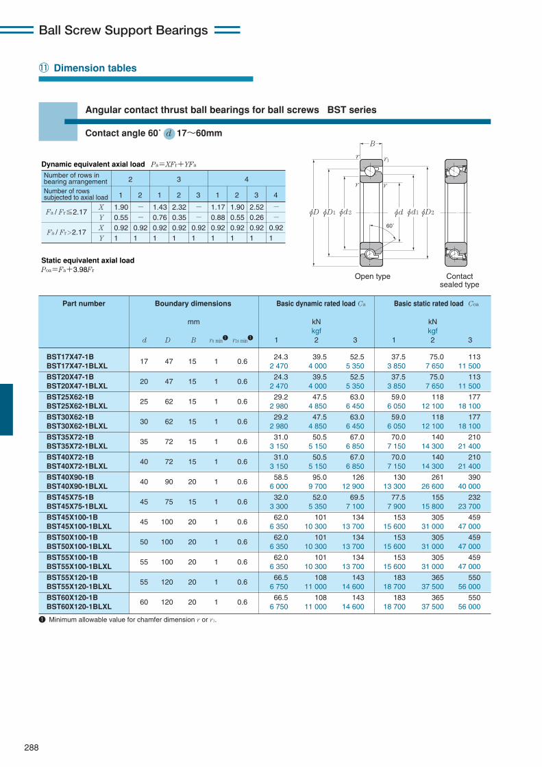
288
Ball Screw Support Bearings
Contactsealed type
Open type
r r1
r r
φd2φD1φD φdφd1φD2
B
60˚
!1 Dimension tables
Angular contact thrust ball bearings for ball screws BST series
Contact angle 60˚ d 17〜60mm
BST17X47-1B17 47 15 1 0.6
24.3 39.5 52.5 37.5 75.0 113BST17X47-1BLXL 2 470 4 000 5 350 3 850 7 650 11 500
BST20X47-1B20 47 15 1 0.6
24.3 39.5 52.5 37.5 75.0 113BST20X47-1BLXL 2 470 4 000 5 350 3 850 7 650 11 500
BST25X62-1B25 62 15 1 0.6
29.2 47.5 63.0 59.0 118 177BST25X62-1BLXL 2 980 4 850 6 450 6 050 12 100 18 100
BST30X62-1B30 62 15 1 0.6
29.2 47.5 63.0 59.0 118 177BST30X62-1BLXL 2 980 4 850 6 450 6 050 12 100 18 100
BST35X72-1B35 72 15 1 0.6
31.0 50.5 67.0 70.0 140 210BST35X72-1BLXL 3 150 5 150 6 850 7 150 14 300 21 400
BST40X72-1B40 72 15 1 0.6
31.0 50.5 67.0 70.0 140 210BST40X72-1BLXL 3 150 5 150 6 850 7 150 14 300 21 400
BST40X90-1B40 90 20 1 0.6
58.5 95.0 126 130 261 390BST40X90-1BLXL 6 000 9 700 12 900 13 300 26 600 40 000
BST45X75-1B45 75 15 1 0.6
32.0 52.0 69.5 77.5 155 232BST45X75-1BLXL 3 300 5 350 7 100 7 900 15 800 23 700
BST45X100-1B45 100 20 1 0.6
62.0 101 134 153 305 459BST45X100-1BLXL 6 350 10 300 13 700 15 600 31 000 47 000
BST50X100-1B50 100 20 1 0.6
62.0 101 134 153 305 459BST50X100-1BLXL 6 350 10 300 13 700 15 600 31 000 47 000
BST55X100-1B55 100 20 1 0.6
62.0 101 134 153 305 459BST55X100-1BLXL 6 350 10 300 13 700 15 600 31 000 47 000
BST55X120-1B55 120 20 1 0.6
66.5 108 143 183 365 550BST55X120-1BLXL 6 750 11 000 14 600 18 700 37 500 56 000
BST60X120-1B60 120 20 1 0.6
66.5 108 143 183 365 550BST60X120-1BLXL 6 750 11 000 14 600 18 700 37 500 56 000
主要寸法 基本動定格荷重 Ca 基本静定格荷重 Coa 呼び番号kN kN
mm kgf kgf1列でアキシアル W row When three rowWhen one rowWhen two rowWhen three row
d D B rs min1 r1s min1荷重を受ける場合 bl load bears axial loadbears axial loadbears axial loadbears axial load
Part number Boundary dimensions Basic dynamic rated load Ca Basic static rated load Coa
mm kN kNkgf kgf
d D B rs min1 r1s min1 1 2 3 1 2 3
Dynamic equivalent axial load Pa=XFr+YFa
Static equivalent axial load Poa=Fa+3.98Fr
Number of rows in bearing arrangementNumber of rows subjected to axial load
2
1
X
Y
X
Y
1.90 0.55 0.92 1
- - 0.92 1
1.43 0.76 0.92 1
2.32 0.35 0.92 1
- - 0.92 1
1.17 0.88 0.92 1
1.90 0.55 0.92 1
2.52 0.26 0.92 1
- - 0.92 1
2 1 2 3 1 2 3 4
3 4
Fa / Fr≦2.17
Fa / Fr>2.17
1 Minimum allowable value for chamfer dimension r or r1.
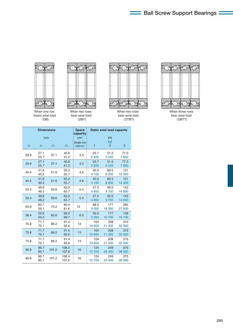
289
Ball Screw Support Bearings
When one row bears axial load
(DB)
When two rows bear axial load(DBT)
When two rows bear axial load(DTBT)
When three rowsbear axial load(DBTT)
29.9 27.1
37.1 40.8
3.3 25.7 51.5 77.0
25.7 41.2 2 620 5 250 7 850
29.9 27.1
37.1 40.8
3.3 25.7 51.5 77.0
25.7 41.2 2 620 5 250 7 850
44.4 41.6
51.6 55.3
4.640.0 80.5 121
40.2 55.7 4 100 8 200 12 300
44.4 41.6
51.6 55.3
4.6 40.0 80.5 121
40.2 55.7 4 100 8 200 12 300
52.4 49.6
59.6 63.2
5.4 47.5 95.0 143
48.2 63.7 4 850 9 700 14 600
52.4 49.6
59.6 63.2
5.447.5 95.0 143
48.2 63.7 4 850 9 700 14 600
64.8 60.7
75.2 80.4
12 88.5 177 265
59.1 81.6 9 000 18 000 27 000
58.4 55.6
65.6 69.2
6.052.5 177 158
54.2 69.7 5 350 10 700 16 100
75.8 71.7
86.2 91.4
13104 208 315
70.1 92.6 10 600 21 200 32 000
75.8 71.7
86.2 91.4
13104 208 315
70.1 92.6 10 600 21 200 32 000
75.8 71.7
86.2 91.4
13104 208 315
70.1 92.6 10 600 21 200 32 000
90.8 86.7
101.2 106.4
16124 249 375
85.1 107.6 12 700 25 400 38 000
90.8 86.7
101.2 106.4
16124 249 375
85.1 107.6 12 700 25 400 38 000
Dimensions Space Static axial load capacitycapacity
mm cm3 kN
Single-row kgfd1 d2 D1 D2 (approx.) 1 2 3
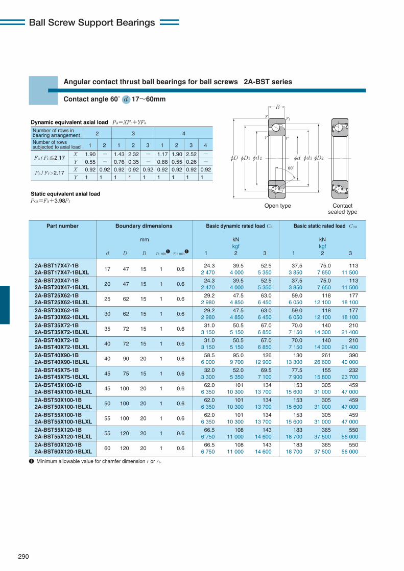
Ball Screw Support Bearings
Contactsealed type
Open type
r r1
r r
φd2φD1φD φdφd1φD2
B
60˚
290
Angular contact thrust ball bearings for ball screws 2A-BST series
Contact angle 60˚ d 17〜60mm
2A-BST17X47-1B17 47 15 1 0.6
24.3 39.5 52.5 37.5 75.0 1132A-BST17X47-1BLXL 2 470 4 000 5 350 3 850 7 650 11 500
2A-BST20X47-1B20 47 15 1 0.6
24.3 39.5 52.5 37.5 75.0 1132A-BST20X47-1BLXL 2 470 4 000 5 350 3 850 7 650 11 500
2A-BST25X62-1B25 62 15 1 0.6
29.2 47.5 63.0 59.0 118 1772A-BST25X62-1BLXL 2 980 4 850 6 450 6 050 12 100 18 100
2A-BST30X62-1B30 62 15 1 0.6
29.2 47.5 63.0 59.0 118 1772A-BST30X62-1BLXL 2 980 4 850 6 450 6 050 12 100 18 100
2A-BST35X72-1B35 72 15 1 0.6
31.0 50.5 67.0 70.0 140 2102A-BST35X72-1BLXL 3 150 5 150 6 850 7 150 14 300 21 400
2A-BST40X72-1B40 72 15 1 0.6
31.0 50.5 67.0 70.0 140 2102A-BST40X72-1BLXL 3 150 5 150 6 850 7 150 14 300 21 400
2A-BST40X90-1B40 90 20 1 0.6
58.5 95.0 126 130 261 3902A-BST40X90-1BLXL 6 000 9 700 12 900 13 300 26 600 40 000
2A-BST45X75-1B45 75 15 1 0.6
32.0 52.0 69.5 77.5 155 2322A-BST45X75-1BLXL 3 300 5 350 7 100 7 900 15 800 23 700
2A-BST45X100-1B45 100 20 1 0.6
62.0 101 134 153 305 4592A-BST45X100-1BLXL 6 350 10 300 13 700 15 600 31 000 47 000
2A-BST50X100-1B50 100 20 1 0.6
62.0 101 134 153 305 4592A-BST50X100-1BLXL 6 350 10 300 13 700 15 600 31 000 47 000
2A-BST55X100-1B55 100 20 1 0.6
62.0 101 134 153 305 4592A-BST55X100-1BLXL 6 350 10 300 13 700 15 600 31 000 47 000
2A-BST55X120-1B55 120 20 1 0.6
66.5 108 143 183 365 5502A-BST55X120-1BLXL 6 750 11 000 14 600 18 700 37 500 56 000
2A-BST60X120-1B60 120 20 1 0.6
66.5 108 143 183 365 5502A-BST60X120-1BLXL 6 750 11 000 14 600 18 700 37 500 56 000
主要寸法 基本動定格荷重 Ca 基本静定格荷重 Coa 呼び番号kN kN
mm kgf kgf1列でアキシアル W row When three rowWhen one rowWhen two rowWhen three row
d D B rs min1 r1s min1荷重を受ける場合 bl load bears axial loadbears axial loadbears axial loadbears axial load
Part number Boundary dimensions Basic dynamic rated load Ca Basic static rated load Coa
mm kN kNkgf kgf
d D B rs min1 r1s min1 1 2 3 1 2 3
Dynamic equivalent axial load Pa=XFr+YFa
Static equivalent axial load Poa=Fa+3.98Fr
Number of rows in bearing arrangementNumber of rows subjected to axial load
2
1
X
Y
X
Y
1.90 0.55 0.92 1
- - 0.92 1
1.43 0.76 0.92 1
2.32 0.35 0.92 1
- - 0.92 1
1.17 0.88 0.92 1
1.90 0.55 0.92 1
2.52 0.26 0.92 1
- - 0.92 1
2 1 2 3 1 2 3 4
3 4
Fa / Fr≦2.17
Fa / Fr>2.17
1 Minimum allowable value for chamfer dimension r or r1.

291
Ball Screw Support Bearings
29.9 27.1
37.1 40.8
3.3 25.7 51.5 77.0
25.7 41.2 2 620 5 250 7 850
29.9 27.1
37.1 40.8
3.3 25.7 51.5 77.0
25.7 41.2 2 620 5 250 7 850
44.4 41.6
51.6 55.3
4.640.0 80.5 121
40.2 55.7 4 100 8 200 12 300
44.4 41.6
51.6 55.3
4.6 40.0 80.5 121
40.2 55.7 4 100 8 200 12 300
52.4 49.6
59.6 63.2
5.4 47.5 95.0 143
48.2 63.7 4 850 9 700 14 600
52.4 49.6
59.6 63.2
5.447.5 95.0 143
48.2 63.7 4 850 9 700 14 600
64.8 60.7
75.2 80.4
12 88.5 177 265
59.1 81.6 9 000 18 000 27 000
58.4 55.6
65.6 69.2
6.052.5 177 158
54.2 69.7 5 350 10 700 16 100
75.8 71.7
86.2 91.4
13104 208 315
70.1 92.6 10 600 21 200 32 000
75.8 71.7
86.2 91.4
13104 208 315
70.1 92.6 10 600 21 200 32 000
75.8 71.7
86.2 91.4
13104 208 315
70.1 92.6 10 600 21 200 32 000
90.8 86.7
101.2 106.4
16124 249 375
85.1 107.6 12 700 25 400 38 000
90.8 86.7
101.2 106.4
16124 249 375
85.1 107.6 12 700 25 400 38 000
Dimensions Space Static axial load capacitycapacity
mm cm3 kN
Single-row kgfd1 d2 D1 D2 (approx.) 1 2 3
When one row bears axial load
(DB)
When two rows bear axial load(DBT)
When two rows bear axial load(DTBT)
When three rowsbear axial load(DBTT)
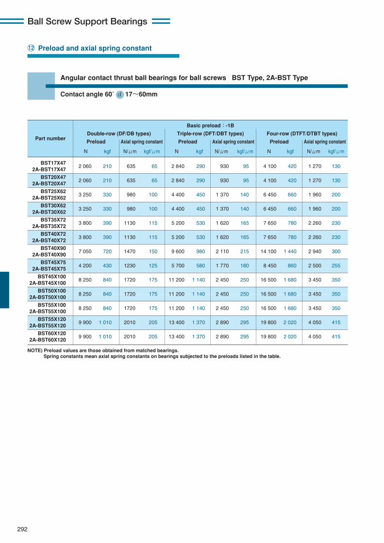
292
Ball Screw Support Bearings
Angular contact thrust ball bearings for ball screws BST Type, 2A-BST Type
!2 Preload and axial spring constant
Contact angle 60˚ d 17〜60mm
BST17X472 060 210 635 65 2 840 290 930 95 4 100 420 1 270 130
2A-BST17X47
BST20X472 060 210 635 65 2 840 290 930 95 4 100 420 1 270 130
2A-BST20X47
BST25X623 250 330 980 100 4 400 450 1 370 140 6 450 660 1 960 200
2A-BST25X62
BST30X623 250 330 980 100 4 400 450 1 370 140 6 450 660 1 960 200
2A-BST30X62
BST35X723 800 390 1130 115 5 200 530 1 620 165 7 650 780 2 260 230
2A-BST35X72
BST40X723 800 390 1130 115 5 200 530 1 620 165 7 650 780 2 260 230
2A-BST40X72
BST40X907 050 720 1470 150 9 600 980 2 110 215 14 100 1 440 2 940 300
2A-BST40X90
BST45X754 200 430 1230 125 5 700 580 1 770 180 8 450 860 2 500 255
2A-BST45X75
BST45X1008 250 840 1720 175 11 200 1 140 2 450 250 16 500 1 680 3 450 350
2A-BST45X100
BST50X1008 250 840 1720 175 11 200 1 140 2 450 250 16 500 1 680 3 450 350
2A-BST50X100
BST55X1008 250 840 1720 175 11 200 1 140 2 450 250 16 500 1 680 3 450 350
2A-BST55X100
BST55X1209 900 1 010 2010 205 13 400 1 370 2 890 295 19 800 2 020 4 050 415
2A-BST55X120
BST60X1209 900 1 010 2010 205 13 400 1 370 2 890 295 19 800 2 020 4 050 415
2A-BST60X120
Basic preload:-1B
Double-row (DF/DB types) Triple-row (DFT/DBT types) Four-row (DTFT/DTBT types)Part number
Preload Axial spring constant Preload Axial spring constant Preload Axial spring constant
N kgf N/μm kgf/μm N kgf N/μm kgf/μm N kgf N/μm kgf/μm
NOTE) Preload values are those obtained from matched bearings.Spring constants mean axial spring constants on bearings subjected to the preloads listed in the table.
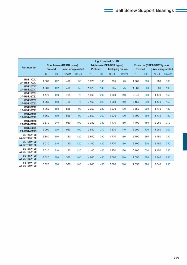
293
Ball Screw Support Bearings
BST17X471 000 102 490 50 1 370 140 735 75 1 960 200 980 100
2A-BST17X47
BST20X471 000 102 490 50 1 370 140 735 75 1 960 200 980 100
2A-BST20X47
BST25X621 470 150 735 75 1 960 200 1 080 110 2 940 300 1 470 150
2A-BST25X62
BST30X621 560 159 735 75 2 160 220 1 080 110 3 150 320 1 470 150
2A-BST30X62
BST35X721 760 180 885 90 2 350 240 1 270 130 3 550 360 1 770 180
2A-BST35X72
BST40X721 860 190 885 90 2 550 260 1 270 130 3 700 380 1 770 180
2A-BST40X72
BST40X902 370 240 980 100 3 230 330 1 470 150 4 700 480 2 060 210
2A-BST40X90
BST45X752 000 200 980 100 2 650 270 1 370 140 3 900 400 1 960 200
2A-BST45X75
BST45X1002 880 290 1 180 120 3 800 390 1 770 180 5 700 580 2 450 250
2A-BST45X100
BST50X1003 010 310 1 180 120 4 100 420 1 770 180 6 100 620 2 450 250
2A-BST50X100
BST55X1003 010 310 1 180 120 4 100 420 1 770 180 6 100 620 2 450 250
2A-BST55X100
BST55X1203 520 360 1 370 140 4 800 490 2 060 210 7 050 720 2 840 290
2A-BST55X120
BST60X1203 520 360 1 370 140 4 800 490 2 060 210 7 050 720 2 840 290
2A-BST60X120
Light preload:-11B
Double-row (DF/DB types) Triple-row (DFT/DBT types) Four-row (DTFT/DTBT types)Part number
Preload Axial spring constant Preload Axial spring constant Preload Axial spring constant
N kgf N/μm kgf/μm N kgf N/μm kgf/μm N kgf N/μm kgf/μm
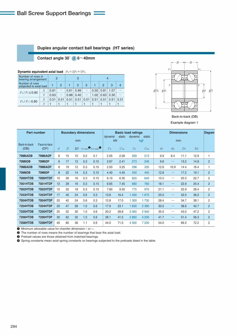
Ball Screw Support Bearings
294
B
φD2 φd φDφd1 φD1 φd2
B B B
φd φD
r r
r rr1
r1 r1
r1
Back-to-back (DB) Face-to-face (DF)
Example diagram 1Example diagram 1
Duplex angular contact ball bearings (HT series)
Contact angle 30˚ d 6〜40mm
79M6ADB 79M6ADF 6 15 10 0.2 0.1 2.05 2.09 209 213 9.9 8.4 11.1 12.9 1
70M6DB 70M6DF 6 17 12 0.3 0.15 2.67 2.41 273 246 9.8 — 13.2 14.8 2
79M8ADB 79M8ADF 8 19 12 0.3 0.15 2.93 3.25 298 335 12.6 10.9 14.4 16.4 1
70M8DB 70M8DF 8 22 14 0.3 0.15 4.40 4.40 450 445 12.8 — 17.2 19.1 2
7000HTDB 7000HTDF 10 26 16 0.3 0.15 6.10 6.30 620 640 15.5 — 20.3 22.7 2
7001HTDB 7001HTDF 12 28 16 0.3 0.15 6.65 7.45 680 760 18.1 — 22.9 25.4 2
7002HTDB 7002HTDF 15 32 18 0.3 0.15 7.60 9.50 775 970 21.1 — 25.9 28.4 2
7203HTDB 7203HTDF 17 40 24 0.6 0.3 13.8 16.4 1 400 1 670 25.0 — 32.0 36.2 2
7004HTDB 7004HTDF 20 42 24 0.6 0.3 12.8 17.0 1 300 1 730 28.4 — 34.7 38.1 2
7204HTDB 7204HTDF 20 47 28 1.0 0.6 17.9 23.1 1 830 2 360 30.5 — 38.6 42.7 2
7205HTDB 7205HTDF 25 52 30 1.0 0.6 20.2 28.8 2 060 2 940 35.0 — 43.0 47.2 2
7206HTDB 7206HTDF 30 62 32 1.0 0.6 28.1 41.5 2 860 4 200 41.7 — 51.4 56.3 2
7208HTDB 7208HTDF 40 80 36 1.1 0.6 44.0 71.0 4 500 7 200 54.0 — 66.0 72.2 2
Part number Boundary dimensions Basic load ratings Dimensions Diagramdynamic static dynamic static
mm kN kgf mmBack-to-back Face-to-face
(DB) (DF) d D 2B rs min1r1s min1 Ca Coa Ca Coa d1 d2 D1 D2
1 Minimum allowable value for chamfer dimension r or r1.2 The number of rows means the number of bearings that bear the axial load.3 Preload values are those obtained from matched bearings.4 Spring constants mean axial spring constants on bearings subjected to the preloads listed in the table.
Dynamic equivalent axial load Pa=XFr+YFa
Number of rows in bearing arrangementNumber of rows subjected to axial load
2
1
X
Y
X
Y
0.81 0.63 0.51 1
- - 0.51 1
0.61 0.88 0.51 1
0.99 0.40 0.51 1
- - 0.51 1
0.50 1.02 0.51 1
0.81 0.63 0.51 1
1.07 0.30 0.51 1
- - 0.51 1
2 1 2 3 1 2 3 4
3 4
Fa / Fr≦0.80
Fa / Fr>0.80
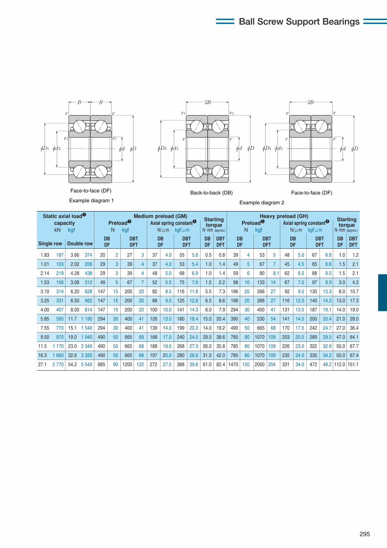
295
Ball Screw Support Bearings
B
φD2 φd φDφd1 φD1 φd2
B B B
φd φD
r r
r rr1
r1 r1
r1
Back-to-back (DB) Face-to-face (DF)
Example diagram 1Example diagram 1
Back-to-back (DB) Face-to-face (DF)
Example diagram 2
2B 2B
φD2 φd φDφd1 φD1 φd1 φd φD
r r r r
r1 r1 r r
1.83 187 3.66 374 20 2 27 3 37 4.0 55 5.6 0.5 0.8 39 4 53 5 48 5.0 67 6.8 1.0 1.2
1.01 103 2.02 206 29 3 39 4 37 4.0 53 5.4 1.0 1.4 49 5 67 7 45 4.5 65 6.6 1.5 2.1
2.14 219 4.28 438 29 3 39 4 48 5.0 68 6.9 1.0 1.4 59 6 80 8.1 62 6.5 88 9.0 1.5 2.1
1.53 156 3.06 312 49 5 67 7 52 5.5 75 7.6 1.5 2.2 98 10 133 14 67 7.0 97 9.9 3.0 4.2
3.10 314 6.20 628 147 15 200 20 82 8.5 116 11.8 5.5 7.3 196 20 266 27 92 9.5 130 13.3 8.0 10.7
3.25 331 6.50 662 147 15 200 20 88 9.0 125 12.8 6.5 8.6 196 20 266 27 116 12.0 140 14.3 13.0 17.3
4.00 407 8.00 814 147 15 200 20 100 10.0 141 14.3 6.0 7.9 294 30 400 41 131 13.5 187 19.1 14.0 19.0
5.85 595 11.7 1 190 294 30 400 41 126 13.0 180 18.4 15.0 20.4 390 40 530 54 141 14.5 200 20.4 21.0 28.0
7.55 770 15.1 1 540 294 30 400 41 139 14.0 199 20.3 14.0 19.2 490 50 665 68 170 17.5 242 24.7 27.0 36.4
9.50 970 19.0 1 940 490 50 665 68 168 17.0 240 24.5 29.0 38.6 785 80 1070 109 203 20.5 289 29.5 47.0 64.1
11.5 1 170 23.0 2 340 490 50 665 68 188 19.0 268 27.3 26.0 35.8 785 80 1070 109 226 23.0 322 32.9 50.0 67.7
16.3 1 660 32.6 3 320 490 50 665 68 197 20.0 280 28.6 31.0 42.0 785 80 1070 109 235 24.0 335 34.2 50.0 67.4
27.1 2 770 54.2 5 540 885 90 1200 122 272 27.5 388 39.6 61.0 82.4 1470 150 2000 204 331 34.0 472 48.2 112.0 151.1
Static axial load2 Medium preload (GM)Starting
Heavy preload (GH)Starting
capacity Preload3 Axial spring constant4 torque Preload3 Axial spring constant4 torquekN kgf N kgf N/μm kgf/μm N・mm (approx.) N kgf N/μm kgf/μm N・mm (approx.)
DB DBT DB DBT DB DBT DB DBT DB DBT DB DBTSingle row Double row DF DFT DF DFT DF DFT DF DFT DF DFT DF DFT
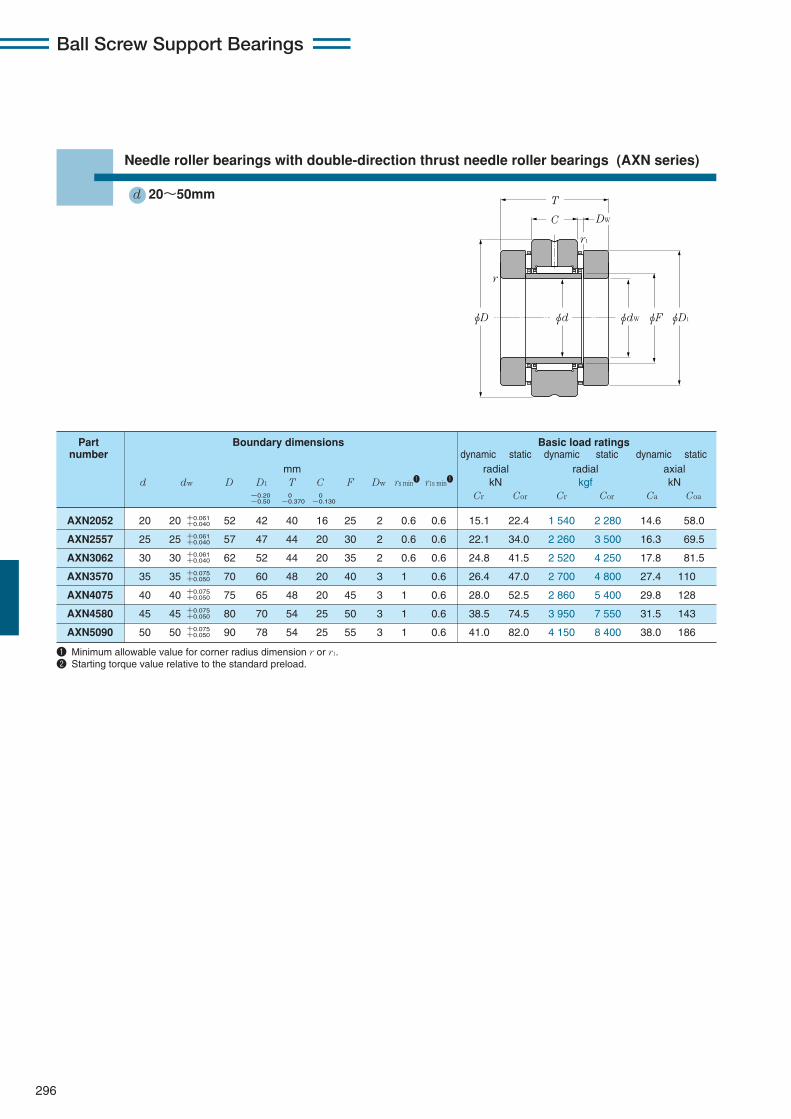
Ball Screw Support Bearings
296
φD φdW φF φD1
T
C
r
φd
r1
DW
AXN2052 20 20 52 42 40 16 25 2 0.6 0.6 15.1 22.4 1 540 2 280 14.6 58.0
AXN2557 25 25 57 47 44 20 30 2 0.6 0.6 22.1 34.0 2 260 3 500 16.3 69.5
AXN3062 30 30 62 52 44 20 35 2 0.6 0.6 24.8 41.5 2 520 4 250 17.8 81.5
AXN3570 35 35 70 60 48 20 40 3 1 0.6 26.4 47.0 2 700 4 800 27.4 110
AXN4075 40 40 75 65 48 20 45 3 1 0.6 28.0 52.5 2 860 5 400 29.8 128
AXN4580 45 45 80 70 54 25 50 3 1 0.6 38.5 74.5 3 950 7 550 31.5 143
AXN5090 50 50 90 78 54 25 55 3 1 0.6 41.0 82.0 4 150 8 400 38.0 186
Part Boundary dimensions Basic load ratingsnumber dynamic static dynamic static dynamic static
mm radial radial axiald dw D D1 T C F Dw rs min1 r1s min1 kN kgf kN
Cr Cor Cr Cor Ca Coa
1 Minimum allowable value for corner radius dimension r or r1.2 Starting torque value relative to the standard preload.
Needle roller bearings with double-direction thrust needle roller bearings (AXN series)
d 20〜50mm
+0.061+0.040
−0.20−0.50
0−0.370
0−0.130
+0.061+0.040
+0.061+0.040
+0.075+0.050
+0.075+0.050
+0.075+0.050
+0.075+0.050

297
Ball Screw Support Bearings
1 490 5 900 1 800 7 000 10 30 39 46 0.6 0.6 1 300 330 0.400 AXN2052
1 660 7 100 1 500 6 000 10 30 44 51 0.6 0.6 1 450 400 0.520 AXN2557
1 820 8 300 1 400 5 500 10 40 50 56 0.6 0.6 1 600 550 0.590 AXN3062
2 790 11 300 1 200 4 700 10 40 56 64 1 0.6 2 450 900 0.800 AXN3570
3 050 13 100 1 100 4 300 10 40 62 69 1 0.6 2 650 1 050 0.890 AXN4075
3 250 14 500 1 000 3 900 10 40 67 74 1 0.6 2 800 1 200 1.00 AXN4580
3 850 19 000 900 3 500 15 50 75 83 1 0.6 3 400 1 600 1.42 AXN5090
Basic load ratings Limiting Radial Abutment and Preload Starting 2 Mass Partdynamic static speeds clearance fillet dimensions torque number
axial min-1 μm mm N N・mm kgkgf grease oil da Da ras r1as
Ca Coa lubrication lubrication min max min max max max (approx.) (approx.)
φda
ra
φDa
r1a

Ball Screw Support Bearings
298
φD
C
T
φdW φF φD1φd
r1
r
DW
Part Boundary dimensions Basic load ratingsnumber dynamic static dynamic static dynamic static
mm radial radial axiald dw D D1 T C F Dw rs min1 r1s min1 kN kgf kN
Cr Cor Cr Cor Ca Coa
1 Minimum allowable value for corner radius dimension r or r1.2 Starting torque value relative to the standard preload.
Needle roller bearings with double-direction thrust cylindrical roller bearings (ARN series)
d 20〜70mm
+0.061+0.040
+0.061+0.040
+0.061+0.040
+0.061+0.040
+0.061+0.040
+0.061+0.040
+0.075+0.050
+0.075+0.050
+0.075+0.050
+0.075+0.050
+0.075+0.050
+0.075+0.050
+0.075+0.050
+0.075+0.050
+0.090+0.060
+0.090+0.060
+0.090+0.060
+0.090+0.060
−0.20−0.50
0−0.370
0−0.130
ARN2052T2 20 20 52 42 46 16 25 5 0.6 0.6 15.1 22.4 1 540 2 280 27.3 68.0
ARN2062 20 20 62 52 60 20 30 7.5 1 0.6 22.1 34.0 2 260 3 500 53.5 129
ARN2557T2 25 25 57 47 50 20 30 5 0.6 0.6 22.1 34.0 2 260 3 500 27.8 72.5
ARN2572 25 25 72 62 60 20 35 7.5 1 0.6 24.8 41.5 2 520 4 250 54.5 139
ARN3062T2 30 30 62 52 50 20 35 5 0.6 0.6 24.8 41.5 2 520 4 250 31.0 87.0
ARN3080 30 30 80 68 66 20 40 9 1 0.6 26.4 47.0 2 700 4 800 74.5 190
ARN3570T2 35 35 70 60 54 20 40 6 1 0.6 26.4 47.0 2 700 4 800 43.0 121
ARN3585 35 35 85 73 66 20 45 9 1 0.6 28.0 52.5 2 860 5 400 82.0 222
ARN4075T2 40 40 75 65 54 20 45 6 1 0.6 28.0 52.5 2 860 5 400 45.5 135
ARN4090 40 40 90 78 75 25 50 9 1 0.6 38.5 74.5 3 950 7 550 85.0 238
ARN4580T2 45 45 80 70 60 25 50 6 1 0.6 38.5 74.5 3 950 7 550 48.0 150
ARN45105 45 45 105 90 82 25 55 11 1 0.6 41.0 82.0 4 150 8 400 121 340
ARN5090 50 50 90 78 60 25 55 6 1 0.6 41.0 82.0 4 150 8 400 62.5 215
ARN50110 50 50 110 95 82 25 60 11 1.1 0.6 41.0 85.0 4 200 8 700 125 365
ARN55115 55 55 115 100 82 25 65 11 1.1 0.6 44.5 98.0 4 550 10 000 130 385
ARN60120 60 60 120 105 82 25 70 11 1.1 0.6 45.0 91.5 4 600 9 350 134 410
ARN65125 65 65 125 110 82 25 75 11 1.1 0.6 55.0 104 5 600 10 600 138 435
ARN70130 70 70 130 115 82 25 80 11 1.1 0.6 57.0 119 5 800 12 200 142 460
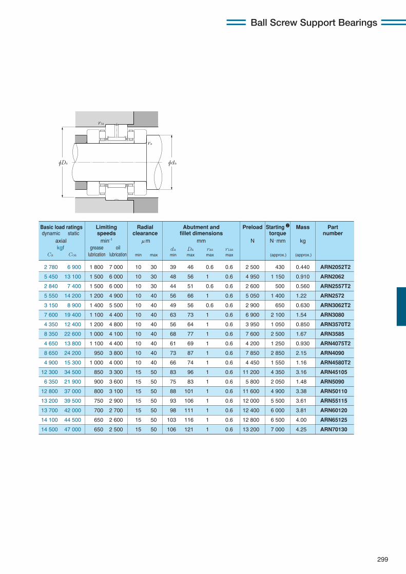
299
Ball Screw Support Bearings
2 780 6 900 1 800 7 000 10 30 39 46 0.6 0.6 2 500 430 0.440 ARN2052T2
5 450 13 100 1 500 6 000 10 30 48 56 1 0.6 4 950 1 150 0.910 ARN2062
2 840 7 400 1 500 6 000 10 30 44 51 0.6 0.6 2 600 500 0.560 ARN2557T2
5 550 14 200 1 200 4 900 10 40 56 66 1 0.6 5 050 1 400 1.22 ARN2572
3 150 8 900 1 400 5 500 10 40 49 56 0.6 0.6 2 900 650 0.630 ARN3062T2
7 600 19 400 1 100 4 400 10 40 63 73 1 0.6 6 900 2 100 1.54 ARN3080
4 350 12 400 1 200 4 800 10 40 56 64 1 0.6 3 950 1 050 0.850 ARN3570T2
8 350 22 600 1 000 4 100 10 40 68 77 1 0.6 7 600 2 500 1.67 ARN3585
4 650 13 800 1 100 4 400 10 40 61 69 1 0.6 4 200 1 250 0.930 ARN4075T2
8 650 24 200 950 3 800 10 40 73 87 1 0.6 7 850 2 850 2.15 ARN4090
4 900 15 300 1 000 4 000 10 40 66 74 1 0.6 4 450 1 550 1.16 ARN4580T2
12 300 34 500 850 3 300 15 50 83 96 1 0.6 11 200 4 350 3.16 ARN45105
6 350 21 900 900 3 600 15 50 75 83 1 0.6 5 800 2 050 1.48 ARN5090
12 800 37 000 800 3 100 15 50 88 101 1 0.6 11 600 4 900 3.38 ARN50110
13 200 39 500 750 2 900 15 50 93 106 1 0.6 12 000 5 500 3.61 ARN55115
13 700 42 000 700 2 700 15 50 98 111 1 0.6 12 400 6 000 3.81 ARN60120
14 100 44 500 650 2 600 15 50 103 116 1 0.6 12 800 6 500 4.00 ARN65125
14 500 47 000 650 2 500 15 50 106 121 1 0.6 13 200 7 000 4.25 ARN70130
ra
r1a
φDa φda
Basic load ratings Limiting Radial Abutment and Preload Starting 2 Mass Partdynamic static speeds clearance fillet dimensions torque number
axial min-1 μm mm N N・mm kgkgf grease oil da Da ras r1as
Ca Coa lubrication lubrication min max min max max max (approx.) (approx.)
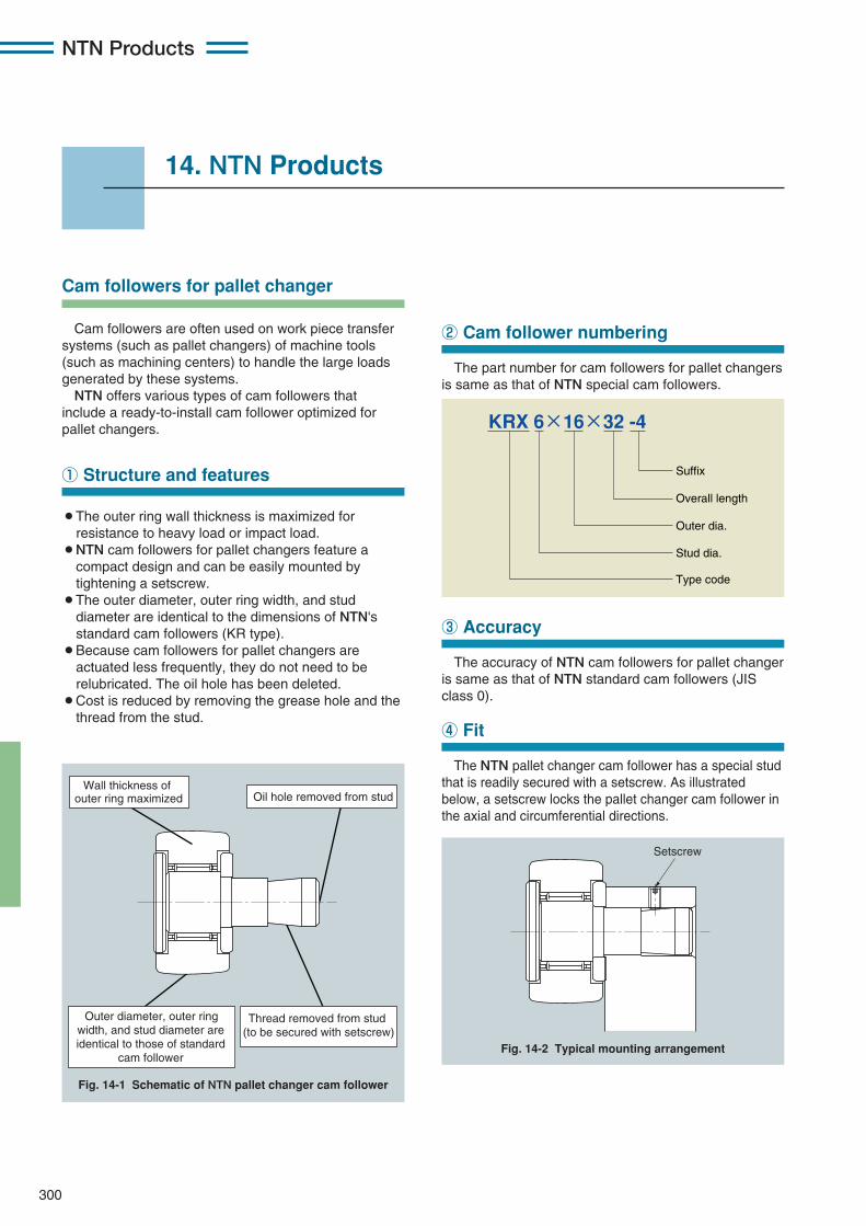
300
NTN Products
The part number for cam followers for pallet changersis same as that of NTN special cam followers.
14. NTN Products
Cam followers are often used on work piece transfersystems (such as pallet changers) of machine tools(such as machining centers) to handle the large loadsgenerated by these systems.
NTN offers various types of cam followers thatinclude a ready-to-install cam follower optimized forpallet changers.
¡The outer ring wall thickness is maximized forresistance to heavy load or impact load.
¡NTN cam followers for pallet changers feature acompact design and can be easily mounted bytightening a setscrew.
¡The outer diameter, outer ring width, and studdiameter are identical to the dimensions of NTN'sstandard cam followers (KR type).
¡Because cam followers for pallet changers areactuated less frequently, they do not need to berelubricated. The oil hole has been deleted.
¡Cost is reduced by removing the grease hole and thethread from the stud.
① Structure and features
Oil hole removed from stud
Thread removed from stud (to be secured with setscrew)
Wall thickness of outer ring maximized
Outer diameter, outer ring width, and stud diameter are identical to those of standard
cam follower
Fig. 14-1 Schematic of NTN pallet changer cam follower
Setscrew
Fig. 14-2 Typical mounting arrangement
② Cam follower numbering
The accuracy of NTN cam followers for pallet changeris same as that of NTN standard cam followers (JISclass 0).
③ Accuracy
The NTN pallet changer cam follower has a special studthat is readily secured with a setscrew. As illustratedbelow, a setscrew locks the pallet changer cam follower inthe axial and circumferential directions.
④ Fit
Suffix
Overall length
Outer dia.
Stud dia.
Type code
KRX 6×16×32 -4
Cam followers for pallet changer
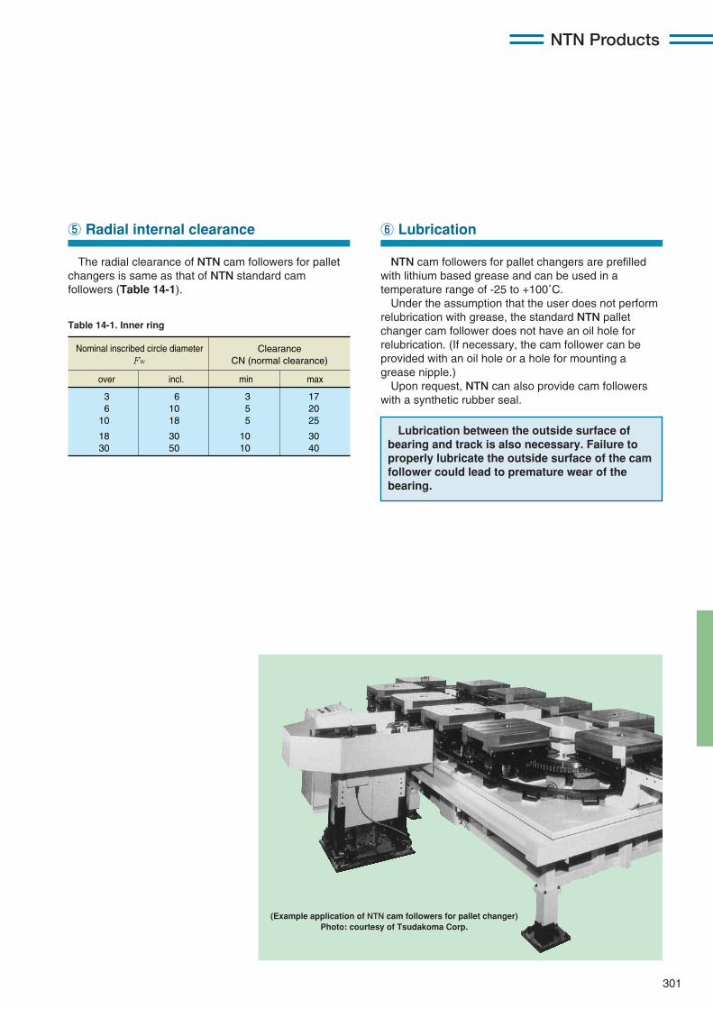
301
NTN Products
The radial clearance of NTN cam followers for palletchangers is same as that of NTN standard camfollowers (Table 14-1).
⑤ Radial internal clearance
NTN cam followers for pallet changers are prefilledwith lithium based grease and can be used in atemperature range of -25 to +100˚C.Under the assumption that the user does not perform
relubrication with grease, the standard NTN palletchanger cam follower does not have an oil hole forrelubrication. (If necessary, the cam follower can beprovided with an oil hole or a hole for mounting agrease nipple.)Upon request, NTN can also provide cam followers
with a synthetic rubber seal.
⑥ Lubrication
(Example application of NTN cam followers for pallet changer)Photo: courtesy of Tsudakoma Corp.
Table 14-1. Inner ring
Nominal inscribed circle diameter Fw
over min maxincl.
Clearance CN (normal clearance)
3 6
10
18 30
6 10 18
30 50
3 5 5
10 10
17 20 25
30 40
Lubrication between the outside surface ofbearing and track is also necessary. Failure toproperly lubricate the outside surface of the camfollower could lead to premature wear of thebearing.
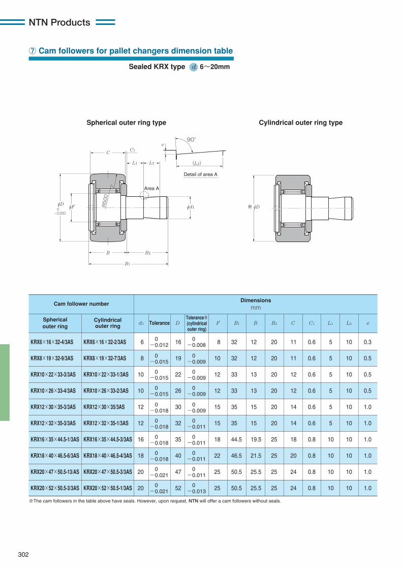
302
NTN Products
⑦ Cam followers for pallet changers dimension table
Sealed KRX type d 6〜20mm
C1
e
(L2)
90°
Detail of area A
R500
Area A
B1
φd1
L1 L2
C
B
φD ※φDφF
B2
0 -0.050
※The cam followers in the table above have seals. However, upon request, NTN will offer a cam followers without seals.
KRX6×16×32-4/3AS KRX6×16×32-2/3AS 6 16 8 32 12 20 11 0.6 5 10 0.3
KRX8×19×32-9/3AS KRX8×19×32-7/3AS 8 19 10 32 12 20 11 0.6 5 10 0.5
KRX10×22×33-3/3AS KRX10×22×33-1/3AS 10 22 12 33 13 20 12 0.6 5 10 0.5
KRX10×26×33-4/3AS KRX10×26×33-2/3AS 10 26 12 33 13 20 12 0.6 5 10 0.5
KRX12×30×35-3/3AS KRX12×30×35/3AS 12 30 15 35 15 20 14 0.6 5 10 1.0
KRX12×32×35-3/3AS KRX12×32×35-1/3AS 12 32 15 35 15 20 14 0.6 5 10 1.0
KRX16×35×44.5-1/3AS KRX16×35×44.5-3/3AS 16 35 18 44.5 19.5 25 18 0.8 10 10 1.0
KRX18×40×46.5-6/3AS KRX18×40×46.5-4/3AS 18 40 22 46.5 21.5 25 20 0.8 10 10 1.0
KRX20×47×50.5-13/AS KRX20×47×50.5-3/3AS 20 47 25 50.5 25.5 25 24 0.8 10 10 1.0
KRX20×52×50.5-3/3AS KRX20×52×50.5-1/3AS 20 52 25 50.5 25.5 25 24 0.8 10 10 1.0
Cam follower number
Sphericalouter ring
Cylindricalouter ring Tolerance
Tolerance※(cylindricalouter ring)
d1 B1 BF B2 C1 L1 L2 eC
Dimensionsmm
0−0.012
0−0.015
0−0.015
0−0.015
0−0.018
0−0.018
0−0.018
0−0.018
0−0.021
0−0.021
0−0.008
0−0.009
0−0.009
0−0.009
0−0.009
0−0.011
0−0.011
0−0.011
0−0.011
0−0.013
Spherical outer ring type Cylindrical outer ring type
D

303
NTN Products
28 16 M6×1 8 — 3
32 20 M8×1.25 10 — 4
36 23 M10×1.25 12 4 4
36 23 M10×1.25 12 4 4
40 25 M12×1.5 13 6 6
40 25 M12×1.5 13 6 6
52 32.5 M16×1.5 17 6 6
58 36.5 M18×1.5 19 6 6
66 40.5 M20×1.5 21 8 8
66 40.5 M20×1.5 21 8 8
(Reference dimensions) mm
Cr Cor
spherical outer ring
cylindricalouter ring
Basic load ratingsdynamic static
Track load capacity
Nkgf
Nkgf
4 050415
4 200430
1 080110
3 400350
4 750480
5 400555
1 380141
4 050415
5 300540
6 650680
1 690172
5 150525
5 300540
6 650680
2 120216
6 100620
7 850800
9 650985
2 620267
7 700785
7 850800
9 650985
2 860291
8 200835
12 2001 240
17 9001 830
3 200325
11 9001 220
14 0001 430
22 8002 330
3 850390
14 5001 480
20 7002 110
33 5003 450
4 700480
21 0002 150
20 7002 110
33 5003 450
5 550565
23 3002 370
B1' B2 G1 n hG
0-0.050
φDφn
φd
1
C C1
B1
B2
G1
G
B
h
(Reference) Standard cam follower KR…H type (w/ hex socket)
The dimensions of standard cam followers (marked with in the diagram above) are different fromthose of NTN pallet changer cam followers. Please see the reference dimensions in the table below.
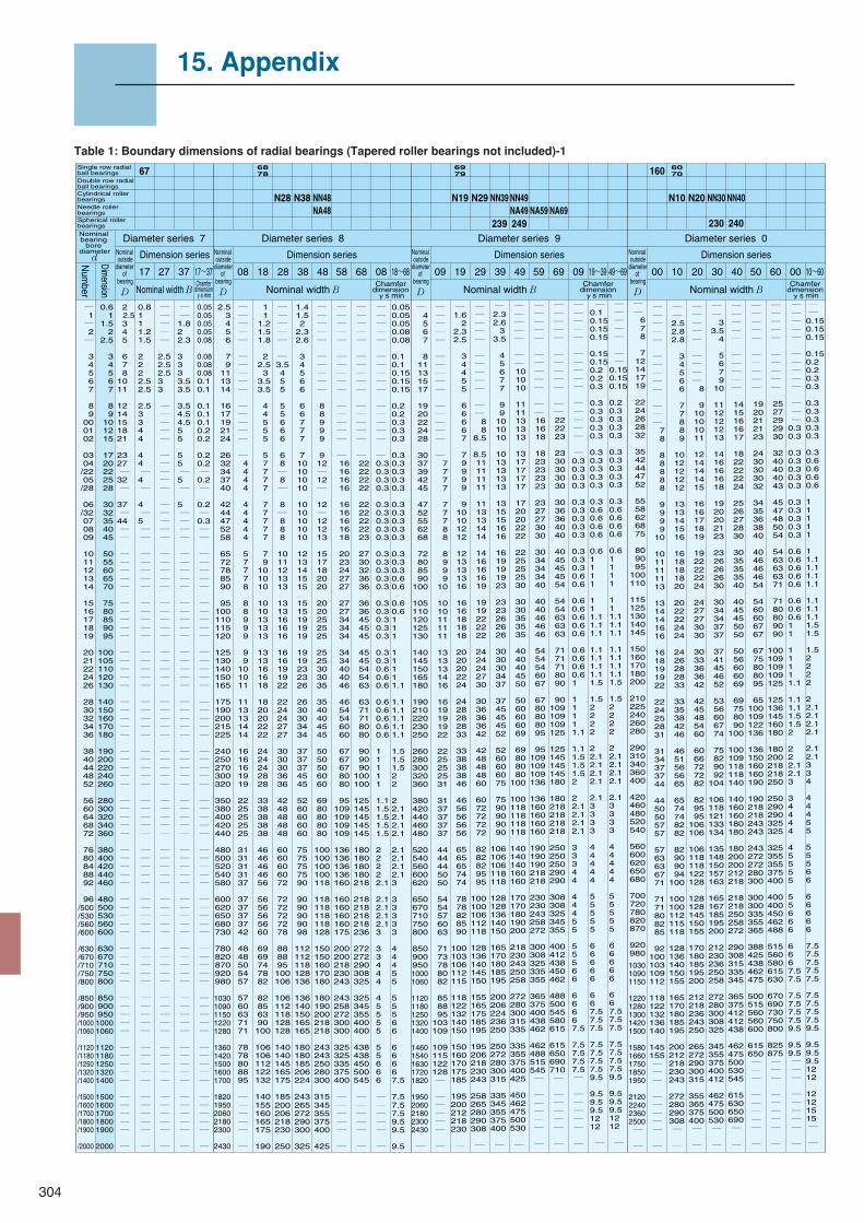
304
― 1 ― 2 ―
3 4 5 6 7
8 9
00 01 02
03 04 /22 05 /28
06 /32 07 08 09
10 11 12 13 14
15 16 17 18 19
20 21 22 24 26
28 30 32 34 36
38 40 44 48 52
56 60 64 68 72
76 80 84 88 92
96
/500 /530 /560 /600
/630 /670 /710 /750 /800
/850 /900 /950 /1000 /1060
/1120 /1180 /1250 /1320 /1400
/1500 /1600 /1700 /1800 /1900
/2000
0.6 1
1.5 2
2.5
3 4 5 6 7
8 9
10 12 15
17 20 22 25 28
30 32 35 40 45
50 55 60 65 70
75 80 85 90 95
100 105 110 120 130
140 150 160 170 180
190 200 220 240 260
280 300 320 340 360
380 400 420 440 460
480 500 530 560 600
630 670 710 750 800
850 900 950 1000 1060
1120 1180 1250 1320 1400
1500 1600 1700 1800 1900
2000
2 2.5
3 4 5
6 7 8 10 11
12 14 15 18 21
23 27 ― 32 ―
37 ― 44 ― ―
― ― ― ― ―
― ― ― ― ―
― ― ― ― ―
― ― ― ― ―
― ― ― ― ―
― ― ― ― ―
― ― ― ― ―
― ― ― ― ―
― ― ― ― ―
― ― ― ― ―
― ― ― ― ―
― ― ― ― ―
―
0.8 1 1 1.2 1.5 2 2 2 2.5 2.5 2.5 3 3 4 4 4 4 ― 4 ― 4 ― 5 ― ― ― ― ― ― ― ― ― ― ― ― ― ― ― ― ― ― ― ― ― ― ― ― ― ― ― ― ― ― ― ― ― ― ― ― ― ― ― ― ― ― ― ― ― ― ― ― ― ― ― ― ― ― ― ― ― ― ― ― ― ― ―
― ― ― ― ― 2.5 2.5 2.5 3 3 ― ― ― ― ― ― ― ― ― ― ― ― ― ― ― ― ― ― ― ― ― ― ― ― ― ― ― ― ― ― ― ― ― ― ― ― ― ― ― ― ― ― ― ― ― ― ― ― ― ― ― ― ― ― ― ― ― ― ― ― ― ― ― ― ― ― ― ― ― ― ― ― ― ― ― ―
― ― 1.8 2 2.3 3 3 3 3.5 3.5 3.5 4.5 4.5 5 5 5 5 ― 5 ― 5 ― ― ― ― ― ― ― ― ― ― ― ― ― ― ― ― ― ― ― ― ― ― ― ― ― ― ― ― ― ― ― ― ― ― ― ― ― ― ― ― ― ― ― ― ― ― ― ― ― ― ― ― ― ― ― ― ― ― ― ― ― ― ― ― ―
0.05 0.05 0.05 0.05 0.08 0.08 0.08 0.08 0.1 0.1 0.1 0.1 0.1 0.2 0.2 0.2 0.2 ― 0.2 ― 0.2 ― 0.3 ― ― ― ― ― ― ― ― ― ― ― ― ― ― ― ― ― ― ― ― ― ― ― ― ― ― ― ― ― ― ― ― ― ― ― ― ― ― ― ― ― ― ― ― ― ― ― ― ― ― ― ― ― ― ― ― ― ― ― ― ― ― ―
2.5 3 4 5 6
7 9
11 13 14
16 17 19 21 24
26 32 34 37 40
42 44 47 52 58
65 72 78 85 90
95
100 110 115 120
125 130 140 150 165
175 190 200 215 225
240 250 270 300 320
350 380 400 420 440
480 500 520 540 580
600 620 650 680 730
780 820 870 920 980
1030 1090 1150 1220 1280
1360 1420 1500 1600 1700
1820 1950 2060 2180 2300
2430
― ― ― ― ― ― ― ― ― ― ― ― ― ― ― ― 4 4 4 4
4 4 4 4 4
5 7 7 7 8
8 8 9 9 9
9 9 10 10 11
11 13 13 14 14
16 16 16 19 19
22 25 25 25 25
31 31 31 31 37
37 37 37 37 42
48 48 50 54 57
57 60 63 71 71
78 78 80 88 95 ― ― ― ― ―
―
1 1
1.2 1.5 1.8
2
2.5 3
3.5 3.5
4 4 5 5 5
5 7 7 7 7
7 7 7 7 7
7 9 10 10 10
10 10 13 13 13
13 13 16 16 18
18 20 20 22 22
24 24 24 28 28
33 38 38 38 38
46 46 46 46 56
56 56 56 56 60
69 69 74 78 82
82 85 63 90
100
106 106 112 122 132
140 155 160 165 175
190
― ― ― ― ― ― 3.5 4 5 5
5 5 6 6 6
6 8 ― 8 ―
8 ― 8 8 8
10 11 12 13 13
13 13 16 16 16
16 16 19 19 22
22 24 24 27 27
30 30 30 36 36
42 48 48 48 48
60 60 60 60 72
72 72 72 72 78
88 88 95
100 106
106 112 118 128 128
140 140 145 165 175
185 200 206 218 230
250
1.4 1.5 2
2.3 2.6
3 4 5 6 6
6 6 7 7 7
7 10 10 10 10
10 10 10 10 10
12 13 14 15 15
15 15 19 19 19
19 19 23 23 26
26 30 30 34 34
37 37 37 45 45
52 60 60 60 60
75 75 75 75 90
90 90 90 90 98
112 112 118 128 136
136 140 150 165 165
180 180 185 206 224
243 265 272 290 300
325
― ― ― ― ― ― ― ― ― ―
8 8 9 9 9
9 12 ― 12 ―
12 ― 12 12 13
15 17 18 20 20
20 20 25 25 25
25 25 30 30 35
35 40 40 45 45
50 50 50 60 60
69 80 80 80 80
100 100 100 100 118
118 118 118 118 128
150 150 160 170 180
180 190 200 218 218
243 243 250 280 300
315 345 355 375 400
425
― ― ― ― ― ― ― ― ― ― ― ― ― ― ― ―
16 16 16 16
16 16 16 16 18
20 23 24 27 27
27 27 34 34 34
34 34 40 40 46
46 54 54 60 60
67 67 67 80 80
95 109 109 109 109
136 136 136 136 160
160 160 160 160 175
200 200 218 230 243
243 258 272 300 300
325 325 335 375 400
― ― ― ― ―
―
― ― ― ― ― ― ― ― ― ― ― ― ― ― ― ―
22 22 22 22
22 22 22 22 23
27 30 32 36 36
36 36 45 45 45
45 45 54 54 63
63 71 71 80 80
90 90 90 100 100
125 145 145 145 145
180 180 180 180 218
218 218 218 218 236
272 272 290 308 325
325 345 355 400 400
438 438 450 500 545
― ― ― ― ―
―
― ― ― ― ― ― ― ― ― ― ― ― ― ― ― ―
0.3 0.3 0.3 0.3
0.3 0.3 0.3 0.3 0.3
0.3 0.3 0.3 0.3 0.3
0.3 0.3 0.3 0.3 0.3
0.3 0.3 0.6 0.6 0.6
0.6 0.6 0.6 0.6 0.6
1 1 1 1 1
1.1 1.5 1.5 1.5 1.5
2 2 2 2
2.1
2.1 2.1 2.1 2.1 3
3 3 4 4 4
4 5 5 5 5
5 5 6 6 6
― ― ― ― ―
―
0.05 0.05 0.05 0.08 0.08
0.1 0.1 0.15 0.15 0.15
0.2 0.2 0.3 0.3 0.3
0.3 0.3 0.3 0.3 0.3
0.3 0.3 0.3 0.3 0.3
0.3 0.3 0.3 0.6 0.6
0.6 0.6 1 1 1
1 1 1 1 1.1
1.1 1.1 1.1 1.1 1.1
1.5 1.5 1.5 2 2
2 2.1 2.1 2.1 2.1
2.1 2.1 2.1 2.1 3
3 3 3 3 3
4 4 4 5 5
5 5 5 6 6
6 6 6 6 7.5
7.5 7.5 7.5 9.5 9.5
9.5
― 4 5 6 7
8
11 13 15 17
19 20 22 24 28
30 37 39 42 45
47 52 55 62 68
72 80 85 90
100
105 110 120 125 130
140 145 150 165 180
190 210 220 230 250
260 280 300 320 360
380 420 440 460 480
520 540 560 600 620
650 670 710 750 800
850 900 950 1000 1060
1120 1180 1250 1320 1400
1460 1540 1630 1720 1820
1950 2060 2180 2300 2430
―
― ― ― ― ―
― ― ― ― ―
― ― ― ― ―
―
7 7 7 7
7 7 7 8 8
8 9 9 9
10
10 10 11 11 11
13 13 13 14 16
16 19 19 19 22
22 25 25 25 31
31 37 37 37 37
44 44 44 50 50
54 54 57 60 63
71 73 78 80 82
85 88 95
103 109
109 115 122 128 ―
― ― ― ― ―
―
― 1.6 2 2.3 2.5
3 4 4 5 5
6 6 6 6 7
7 9 9 9 9
9 10 10 12 12
12 13 13 13 16
16 16 18 18 18
20 20 20 22 24
24 28 28 28 33
33 38 38 38 46
46 56 56 56 56
65 65 65 74 74
78 78 82 85 90
100 103 106 112 115
118 122 132 140 150
150 160 170 175 185
195 200 212 218 230
―
― ― ― ― ― ― ― ― ― ― ― ― 8 8 8.5
8.5 11 11 11 11
11 13 13 14 14
14 16 16 16 19
19 19 22 22 22
24 24 24 27 30
30 36 36 36 42
42 48 48 48 60
60 72 72 72 72
82 82 82 95 95
100 100 106 112 118
128 136 140 145 150
155 165 175 185 195
195 206 218 230 243
258 265 280 290 308
―
― 2.3 2.6 3 3.5
4 5 6 7 7
9 9 10 10 10
10 13 13 13 13
13 15 15 16 16
16 19 19 19 23
23 23 26 26 26
30 30 30 34 37
37 45 45 45 52
52 60 60 60 75
75 90 90 90
90
106 106 106 118 118
128 128 136 140 150
165 170 180 185 195
200 206 224 236 250
250 272 280 300 315
335 345 355 375 400
―
― ― ― ― ― ― ― 10 10 10
11 11 13 13 13
13 17 17 17 17
17 20 20 22 22
22 25 25 25 30
30 30 35 35 35
40 40 40 45 50
50 60 60 60 69
69 80 80 80
100
100 118 118 118 118
140 140 140 160 160
170 170 180 190 200
218 230 243 250 258
272 280 300 315 335
335 355 375 400 425
450 462 475 500 530
―
― ― ― ― ― ― ― ― ― ― ― ― 16 16 18
18 23 23 23 23
23 27 27 30 30
30 34 34 34 40
40 40 46 46 46
54 54 54 60 67
67 80 80 80 95
95
109 109 109 136
136 160 160 160 160
190 190 190 218 218
230 230 243 258 272
300 308 325 335 355
365 375 400 438 462
462 488 515 545 ― ― ― ― ― ― ―
― ― ― ― ― ― ― ― ― ― ― ― 22 22 23
23 30 30 30 30
30 36 36 40 40
40 45 45 45 54
54 54 63 63 63
71 71 71 80 90
90
109 109 109 125
125 145 145 145 180
180 218 218 218 218
250 250 250 290 290
308 308 325 345 355
400 412 438 450 462
488 500 545 580 615
615 650 690 710 ― ― ― ― ― ― ―
― ― ― ― ― ― ― ― ― ― ― ― ― ― ― ― 0.3 0.3 0.3 0.3
0.3 0.3 0.3 0.3 0.3
0.3 0.3 0.3 0.6 0.6
0.6 0.6 0.6 0.6 0.6
0.6 0.6 0.6 0.6 1
1 1 1 1 1.1
1.1 1.5 1.5 1.5 2
2 2.1 2.1 2.1 2.1
3 3 3 4 4
4 4 4 5 5
5 5 5 6 6
6 6 6 6 7.5
7.5 7.5 7.5 7.5 ― ― ― ― ― ― ―
― 0.1 0.15 0.15 0.15 0.15 0.15 0.2 0.2 0.3 0.3 0.3 0.3 0.3 0.3 0.3 0.3 0.3 0.3 0.3 0.3 0.6 0.6 0.6 0.6 0.6 1 1 1 1 1 1 1.1 1.1 1.1 1.1 1.1 1.1 1.1 1.5 1.5 2 2 2 2 2 2.1 2.1 2.1 2.1 2.1 3 3 3 3 4 4 4 4 4 5 5 5 5 5 6 6 6 6 6 6 6 7.5 7.5 7.5 7.5 7.5 7.5 7.5 9.5 9.5 9.5 9.5 12 12 ―
― ― ― ― ― ― ― 0.15 0.15 0.15 0.2 0.3 0.3 0.3 0.3 0.3 0.3 0.3 0.3 0.3 0.3 0.6 0.6 0.6 0.6 0.6 1 1 1 1 1 1 1.1 1.1 1.1 1.1 1.1 1.1 1.1 1.5 1.5 2 2 2 2 2 2.1 2.1 2.1 2.1 2.1 3 3 3 3 4 4 4 4 4 5 5 5 5 5 6 6 6 6 6 6 6 7.5 7.5 7.5 7.5 7.5 7.5 7.5 9.5 9.5 9.5 9.5 12 12 ―
― ―
6 7 8
7
12 14 17 19
22 24 26 28 32
35 42 44 47 52
55 58 62 68 75
80 90 95
100 110
115 125 130 140 145
150 160 170 180 200
210 225 240 260 280
290 310 340 360 400
420 460 480 520 540
560 600 620 650 680
700 720 780 820 870
920 980
1030 1090 1150
1220 1280 1300 1420 1500
1580 1660 1750 1850 1950
2120 2240 2360 2500 ―
―
― ― ― ― ―
― ― ― ― ―
― ― ―
7 8
8 8 8 8 8
9 9 9 9
10
10 11 11 11 13
13 14 14 16 16
16 18 19 19 22
22 24 25 28 31
31 34 37 37 44
44 50 50 57 57
57 63 63 67 71
71 71 80 82 85
92
100 103 109 112
118 122 132 136 140
145 155 ― ― ―
― ― ― ― ―
―
― ― 2.5 2.8 2.8
3 4 5 6 6
7 7 8 8 9
10 12 12 12 12
13 13 14 15 16
16 18 18 18 20
20 22 22 24 24
24 26 28 28 33
33 35 38 42 46
46 51 56 56 65
65 74 74 82 82
82 90 90 94
100
100 100 112 115 118
128 136 140 150 155
165 170 180 185 195
200 212 218
230 243
272 280 290 308 ―
―
― ― ― ― ―
― ― ― ―
8
9 10 10 10 11
12 14 14 14 15
16 16 17 18 19
19 22 22 22 24
24 27 27 30 30
30 33 36 36 42
42 45 48 54 60
60 66 72 72 82
82 95 95
106 106
106 118 118 122 128
128 128 145 150 155
170 180 185 195 200
212 218 236 243 250
265 272 290
300 315
355 365 375 400 ―
―
― ―
3 3.5
4
5 6 7 9
10
11 12 12 12 13
14 16 16 16 18
19 20 20 21 23
23 26 26 26 30
30 34 34 37 37
37 41 45 46 52
53 56 60 67 74
75 82 90 92
104
106 118 121 133 134
135 148 150 157 163
165 167 185 195 200
212 230 236 250 258
272 280 300 308 325
345 355 375
400 412
462 475 500 530 ―
―
― ― ― ― ―
― ― ― ― ―
14 15 16 16 17
18 22 22 22 24
25 26 27 28 30
30 35 35 35 40
40 45 45 50 50
50 56 60 60 69
69 75 80 90
100
100 109 118 118 140
140 160 160 180 180
180 200 200 212 218
218 218 250 258 272
290 308 315 335 345
365 375 412 412 438
462 475 500
530 545
615 630 650 690 ―
―
― ― ― ― ―
― ― ― ― ―
19 20 21 21 23
24 30 30 30 32
34 35 36 38 40
40 46 46 46 54
54 60 60 67 67
67 75 80 80 95
65
100 109 122 136
136 150 160 160 190
190 218 218 243 243
243 272 272 280 300
300 300 335 355 365
388 425 438 462 475
500 515 560 560 600
615 650 ― ― ―
― ― ― ― ―
―
― ― ― ― ―
― ― ― ― ―
25 27 29 29 30
32 40 40 40 43
45 47 48 50 54
54 63 63 63 71
71 80 80 90 90
100 109 109 109 125
125 136 145 160 180
180 200 218 218 250
250 290 290 325 325
325 355 355 375 400
400 400 450 462 488
515 560 580 615 630
670 690 730 750 800
825 875 ― ― ―
― ― ― ― ―
―
― ― ― ― ―
― ― ― ― ―
― ― ―
0.3 0.3
0.3 0.3 0.3 0.3 0.3
0.3 0.3 0.3 0.3 0.3
0.6 0.6 0.6 0.6 0.6
0.6 0.6 0.6 1 1
1 1 1 1 1.1
1.1 1.1 1.5 1.5 2
2 2 2.1 2.1 3
3 4 4 4 4
4 5 5 5 5
5 5 6 6 6
6 6 6 7.5 7.5
7.5 7.5 7.5 7.5 9.5
9.5 9.5 ― ― ―
― ― ― ― ―
―
― ― 0.15 0.15 0.15 0.15 0.2 0.2 0.3 0.3 0.3 0.3 0.3 0.3 0.3 0.3 0.6 0.6 0.6 0.6 1 1 1 1 1 1 1.1 1.1 1.1 1.1 1.1 1.1 1.1 1.5 1.5 1.5 2 2 2 2 2 2.1 2.1 2.1 2.1 2.1 2.1 3 3 4 4 4 4 5 5 5 5 5 6 6 6 6 6 6 6 7.5 7.5 7.5 7.5 7.5 7.5 7.5 7.5 7.5 9.5 9.5 9.5 9.5 12 12 12 12 15 15 ― ―
Dimension series
17 27 37 17~37
Nominal width B
Dimension
Num
ber
Nominal bearing
bore diameter
d
Single row radial ball bearingsDouble row radial ball bearingsCylindrical roller bearingsNeedle roller bearingsSpherical roller bearings
Diameter series 7
Chamfer dimension γs min
Dimension series
28 38 48
Nominal width B
Diameter series 8
Chamfer dimension γs min
08 18 58 68 08 18~68
Dimension series
29 39 49
Nominal width B
Diameter series 9
Chamfer dimension γs min
09 19 59 69 09 19~39 49~69
Dimension series
20 30 40
Nominal width B
Diameter series 0
Chamfer dimension γs min
00 10 50 60 00 10~60
67 68 78
N28 N38 NN48
69 79
NA48N19 N29 NN39 NN49
NA49 NA59 NA69239 249
60 70160
N10 N20 NN30 NN40
230 240
Nominal outside
diameter of
bearing
D
Nominal outside
diameter of
bearing
D
Nominal outside
diameter of
bearing
D
Nominal outside
diameter of
bearing
D
Table 1: Boundary dimensions of radial bearings (Tapered roller bearings not included)-1
15. Appendix
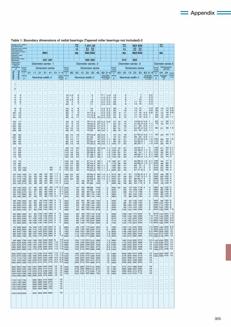
305
Appendix
Table 1: Boundary dimensions of radial bearings (Tapered roller bearings not included)-2
― 1 ― 2 ―
3 4 5 6 7
8 9
00 01 02
03 04 /22 05 /28
06 /32 07 08 09
10 11 12 13 14
15 16 17 18 19
20 21 22 24 26
28 30 32 34 36
38 40 44 48 52
56 60 64 68 72
76 80 84 88 92
96
/500 /530 /560 /600
/630 /670 /710 /750 /800
/850 /900 /950 /1000 /1060
/1120 /1180 /1250 /1320 /1400
/1500
― ― ― ― ―
3 4 5 6 7
8 9
10 12 15
17 20 22 25 28
30 32 35 40 45
50 55 60 65 70
75 80 85 90 95
100 105 110 120 130
140 150 160 170 180
190 200 220 240 260
280 300 320 340 360
380 400 420 440 460
480 500 530 560 600
630 670 710 750 800
850 900 950 1000 1060
1120 1180 1250 1320 1400
1500
― ― ― ― ―
― ― ― ― ―
― ― ― ― ―
― ― ― ― ―
― ― ― ― ―
― ― ― ― ―
― ― ―
150 160
165 175 180 200 210
225 250 270 280 300
320 340 370 400 440
460 500 540 580 600
620 650 700 720 760
790 830 870 920 980
1030 1090 1150 1220 1280
1360 1420 1500 1580 1660
1750 1850 1950 2060 2180
2300
― ― ― ― ―
2.5 3 3.5 4 5
5 6 7 7 8
8 9 9 10 10
10 11 12 13 13
13 14 16 18 18
18 19 21 22 24
25 27 28 ― ― ― ― ― ― ― ― ― ― ― ― ― ― ― ― ― ― ― ― ― ― ― ― ― ― ― ― ― ― ― ― ― ― ― ― ― ― ― ― ― ― ―
― ― ― ― ―
4 5 5 6 7
8 8 9
10 11
12 14 14 15 16
16 17 17 18 19
20 21 22 23 24
25 26 28 30 32
34 36 38 40 40
42 45 48 52 52
55 58 65 72 80
80 85 92 92 95
95
103 109 112 118
125 136 145 150 155
165 175 180 195 200
206 218 230 243 ―
― ― ― ― ―
―
― ― ― ― ―
― ― ― ― ―
― ― ― ― ―
― ― ― ― ―
― ― ― ― ―
― ― ― ― ―
― ― ― ― ―
― ― ― 42 46
50 54 58 62 62
65 70 78 85 90
90 98
105 118 122
132 140 150 155 165
170 185 200 206 212
230 243 250 265 272
280 300 315 330 ―
― ― ― ― ―
―
― ― ― ― ―
― ― ― ― ―
― ― 14 14 14
16 18 18 18 19
20 21 23 23 23
23 25 28 31 31
31 33 36 40 43
46 50 53 58 64
68 73 80 86 86
92 98
108 120 130
130 140 150 165 170
175 185 195 200 212
224 243 258 272 280
300 315 325 345 355
375 388 412 425 ―
― ― ― ― ―
―
― ― ― ― ― 0.1 0.15 0.15 0.2 0.3 0.3 0.3 0.3 0.3 0.3 0.3 0.3 0.3 0.3 0.6 0.6 0.6 0.6 0.6 0.6 0.6 1 1 1 1 1 1 1.1 1.1 1.1 1.5 1.5 1.5 ― ― ― ― ― ― ― ― ― ― ― ― ― ― ― ― ― ― ― ― ― ― ― ― ― ― ― ― ― ― ― ― ― ― ― ― ― ― ― ― ― ― ―
― ― ― ― ―
13 16
19 22 26
28 30 35 37 42
47 52 56 62 68
72 75 80 90
100
110 120 130 140 150
160 170 180 190 200
215 225 240 260 280
300 320 340 360 380
400 420 460 500 540
580 620 670 710 750
780 820 850 900 950
980 1030 1090 1150 1220
1280 1360 1420 1500 1600
1700 1780 1850 1950 ―
― ― ― ― ―
―
― ― ― ― ―
― ― ― ― ―
― ― 9 9 9
10 10 11 12 13
13 14 14 16 17
19 21 22 24 25
27 28 30 30 33
36 37 42 44 48
50 ― ― ― ― ― ― ― ― ― ― ― ― ― ― ― ― ― ― ― ― ― ― ― ― ― ― ― ― ― ― ― ― ― ― ― ― ― ― ― ―
― ― ― ― ―
5 5 6 7 9
9
10 11 12 13
14 15 16 17 18
19 20 21 23 25
27 29 31 33 35
37 39 41 43 45
47 49 50 55 58
62 65 68 72 75
78 80 88 95
102
108 109 112 118 125
128 136 136 145 155
160 170 180 190 200
206 218 224 236 258
272 280 290 300 ―
― ― ― ― ―
―
― ― ― ― ― ― ― ― ― ― ― ― 0.3 0.3 0.3
0.6 0.6 0.6 0.6 0.6
0.6 0.6 0.6 1 1
1 1.1 1.1 1.1 1.5
1.5 1.5 2 2 2
2.1 2.1 3 3 3
4 ― ― ― ― ― ― ― ― ― ― ― ― ― ― ― ― ― ― ― ― ― ― ― ― ― ― ― ― ― ― ― ― ― ― ― ― ― ― ― ―
― ― ― ― ― 0.2 0.3 0.3 0.3 0.3 0.3 0.6 0.6 1 1 1 1.1 1.1 1.1 1.1 1.1 1.1 1.5 1.5 1.5 2 2 2.1 2.1 2.1 2.1 2.1 3 3 3 3 3 3 3 4 4 4 4 4 4 5 5 5 5 6 6 7.5 7.5 7.5 7.5 7.5 7.5 9.5 9.5 9.5 9.5 12 12 12 15 15 15 15 15 15 19 19 19 19 ― ― ― ― ― ― ―
― ― ― ― ―
― ― ― ― ―
30 32 37 42 52
62 72 ― 80 ―
90 ―
100 110 120
130 140 150 160 180
190 200 210 225 240
250 260 280 310 340
360 380 400 420 440
460 480 540 580 620
670 710 750 800 850
900 950 980 1030 1060
1120 1150 1220 1280 1360
1420 1500 ― ― ―
― ― ― ― ―
― ― ― ― ―
―
― ― ― ― ―
― ― ― ― ―
10 11 12 13 15
17 19 ― 21 ―
23 ― 25 27 29
31 33 35 37 42
45 48 52 54 55
58 60 65 72 78
82 85 88 92 95
98
102 115 122 132
140 150 155 164 180
190 200 206 212 218
230 236 250 258 272
280 290 ― ― ―
― ― ― ― ―
― ― ― ― ―
―
Dimension series
01 11 21 11~41
Nominal width B
Nominal outside
diameter of
bearing
D
Nominal outside
diameter of
bearing
D
Nominal outside
diameter of
bearing
D
Nominal outside
diameter of
bearing
D
Nominal bearing
bore diameter
d
Diameter series 1
Chamfer dimension γs min
Dimension series
82 02
Nominal width B
Diameter series 2
Chamfer dimension γs min
Chamfer dimension γs min
41 01 12 22 32 02~42
Dimension series
83 03 13
Nominal width B
Diameter series 3
42 23 33 83 03~33
Dimension series
Nominal width
B
Diameter series 4
04 24
231
62 72
N22
222
― ― ― ― ―
― ― ― ― ―
― ― ― ― ―
― ― ― ― ―
― ― ― ― ―
― ― ― ― ―
― ― ― ― ―
21 22 22 25 25
27 31 34 34 37
42 44 48 50 57
57 63 71 78 78
78 80 88 88 95
100 106 109 115 122
128 136 140 150 155
165 165 175 185 190
― ― ― ― ―
―
― ― ― ― ―
― ― ― ― ―
― ― ― ― ―
― ― ― ― ―
― ― ― ― ―
― ― ― ― ―
― ― ― ― ―
30 33 33 38 38
40 46 51 51 56
60 65 69 74 82
82 90
100 106 106
106 112 122 122 132
136 145 150 160 170
175 185 195 206 212
224 230 243 258 265
280 290 308 325 345
355
― ― ― ― ―
―
― ― ― ―
― ― ― ― ―
― ― ― ― ―
― ― ― ― ―
― ― ― ― ―
― ― ― ― ―
39 42 42 48 48
50 60 66 66 72
78 82 88 95
106
106 118 128 140 140
140 145 165 165 175
180 190 195 206 218
230 243 250 272 272
290 300 315 335 345
365 388 400 425 450
462
― ― ― ― ―
―
― ― ― ―
― ― ― ― ―
― ― ― ― ―
― ― ― ― ―
― ― ― ― ―
― ― ― ― ―
52 56 56 62 64
68 80 86 88 96
104 112 120 128 144
146 160 176 190 192
194 200 224 226 240
248 264 272 280 300
315 336 345 365 375
400 412 438 462 475
475 500 530 560 580
600
― ― ― ― ―
―
― ― ― ―
― ― ― ― ―
― ― ― ― ―
― ― ― ― ―
― ― ― ― ―
― ― ― 60 65
65 69 69 80 80
85
100 109 109 118
128 140 150 160 180
180 200 218 243 243
243 250 280 280 300
308 325 335 355 375
400 412 438 475 475
500 515 545 580 600
630 670 710 750 775
800
― ― ― ― ― ― ― ― ― ― ― ― ― ― ― ― ― ― ― ― ― ― ― ― ― ― ― ― ― ― ― ― ― ― ― 1.1 1.1 1.1 1.5 1.5 1.5 2 2 2 2.1 3 3 3 4 4 4 5 5 5 5 5 6 6 6 6 6 7.5 7.5 7.5 7.5 7.5 7.5 9.5 9.5 9.5 12 12 12 12 12 ― ― ― ― ― ―
― ― ― ― ― ― ― ― ― ― ― ― ― ― ― ― ― ― ― ― ― ― ― ― ― ― ― ― ― ― ― ― ― 2 2 2 2 2 2 2 2.1 2.1 2.1 2.1 3 3 3 4 4 4 5 5 5 5 5 5 6 6 6 7.5 7.5 7.5 7.5 7.5 7.5 7.5 7.5 9.5 9.5 9.5 12 12 12 12 15 15 15 15 15 19 19
31 82
― ― ― ― ―
10 13 16 19 22
24 26 30 32 35
40 47 50 52 58
62 65 72 80 85
90
100 110 125 125
130 140 150 160 170
180 190 200 215 230
250 270 290 310 320
340 360 400 440 480
500 540 580 620 650
680 720 760 790 830
870 920 980 1030 1090
1150 1220 1280 1360 1420
1500 1580 1660 1750 ―
― ― ― ― ―
―
― ― ― ― ― 5 7 8 10 11 12 13 14.3 15.9 15.9 17.5 20.6 20.6 20.6 23 23.8 25 27 30.2 30.2 30.2 33.3 36.5 38.1 39.7 41.3 44.4 49.2 52.4 55.6 60.3 65.1 69.8 76 80 88 96 104 110 112 120 128 144 160 174 176 192 208 224 232 240 256 272 280 296 310 336 355 365 388 412 438 450 475 488 515 515 530 560 ― ― ― ― ― ― ―
― ― ― ― ―
― ― ― ― ―
― ― ― ― 20
22 27 27 27 30
32 33 37 40 40
40 45 50 56 56
56 60 65 69 75
80 85 90 95
100
109 118 128 140 140
150 160 180 200 218
218 243 258 280 290
300 315 335 345 365
388 412 450 475 488
515 545 560 615 615
650 670 710 750 ―
― ― ― ― ―
―
― ― ― ― ― 0.15 0.2 0.3 0.3 0.3 0.3 0.3 0.6 0.6 0.6 0.6 1 1 1 1 1 1 1.1 1.1 1.1 1.1 1.5 1.5 1.5 1.5 1.5 2 2 2 2.1 2.1 2.1 2.1 2.1 3 3 3 3 4 4 4 4 4 4 5 5 5 5 6 6 6 6 7.5 7.5 7.5 7.5 7.5 9.5 9.5 9.5 12 12 12 15 15 15 15 15 15 ― ― ― ― ― ― ―
― ― ― ― ―
― ― ― ― ―
― ― ― ― ―
― ― ― ― ―
― ― ― ― ―
― ― ― ― ―
― ― ― ― ―
51 53 57 62 66
70 75 79 84 88
92 97
106 114 123
132 140 155 165 170
175 185 190 200 212
218 230 243 258 272
280 300 308 325 355
375 388 400 412 ―
― ― ― ― ―
―
― ― ― ― ―
― ― ― 11 13
13 14 17 17 17
19 21 21 24 24
27 28 31 33 36
40 43 46 48 51
55 58 60 64 67
73 77 80 86 93
102 108 114 120 126
132 138 145 155 165
175 185 200 212 224
230 243 250 265 280
290 300 325 335 355
375 400 412 438 462
488 500 515 545 ―
― ― ― ― ―
―
― ― ― ― ―
7 9 10 13 15
15 16 19 19 19
22.2 22.2 25
25.4 30
30.2 32
34.9 36.5 39.7
44.4 49.2 54
58.7 63.5
68.3 68.3 73 73
77.8
82.6 87.3 92.1 106 112
118 128 136 140 150
155 165 180 195 206
224 236 258 272 290
300 308 315 345 365
375 388 412 438 462
488 515 530 560 600
630 650 670 710 ― ― ― ― ― ― ―
― ― ― ― ―
― ― ― ― ―
14 15 16 19 24
29 33 ― 36 ―
40 ― 43 46 50
53 57 60 64 74
77 80 86 90 95
98
100 108 118 128
132 138 142 145 150
155 160 180 190 206
224 236 250 265 280
300 315 325 335 345
365 375 400 412 438
450 475 ― ― ―
― ― ― ― ―
― ― ― ― ―
―
― ― ― ― ― ― ― ― ― ― 0.6 0.6 0.6 1 1.1 1.1 1.1 ― 1.5 ― 1.5 ― 1.5 2 2 2.1 2.1 2.1 2.1 3 3 3 4 4 4 4 4 4 5 5 5 5 5 5 6 6 6 6 6 7.5 7.5 7.5 9.5 9.5 9.5 9.5 12 12 12 12 15 15 15 15 15 15 15 ― ― ― ― ― ― ― ― ― ― ― ― ― ―
241
NN3112
N32
232
42 22
52 32
N2
1,22 1,32 63 73
N23
213
13N33
223
43 23
53 33
N3
623 633 64 74
N4
Single row radial ball bearingsDouble row radial ball bearingsCylindrical roller bearingsNeedle roller bearingsSpherical roller bearings
Dimension
Num
ber
Chamfer dimension γs min
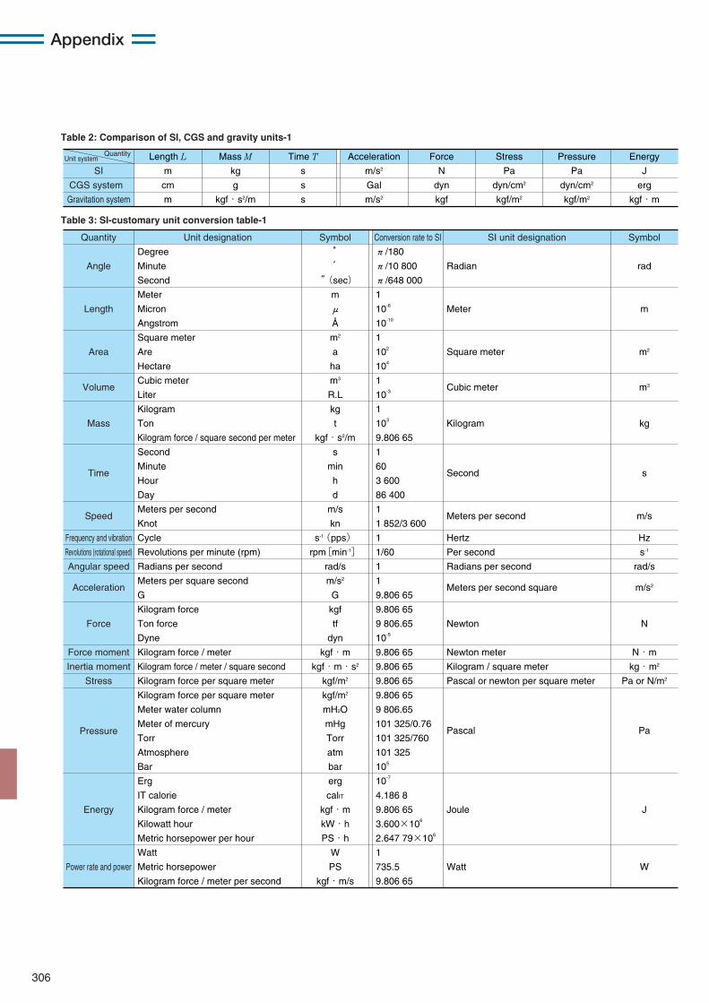
306
Appendix
Energy
J
erg
kgf・m
Pressure
Pa
dyn/cm2
kgf/m2
Stress
Pa
dyn/cm2
kgf/m2
Force
N
dyn
kgf
Acceleration
m/s2
Gal
m/s2
Time T
s
s
s
Mass M
kg
g
kgf・s2/m
Length L
m
cm
m
SI
CGS system
Gravitation system
Unit systemQuantity
Symbol
rad
m
m2
m3
kg
s
m/s
Hz
s-1
rad/s
m/s2
N
N・m
kg・m2
Pa or N/m2
Pa
J
W
SI unit designationSymbol
° ′
″(sec)
m
μ
Å
m2
a
ha
m3
R.L
kg
t
kgf・s2/m
s
min
h
d
m/s
kn
s-1(pps)
rpm[min-1]
rad/s
m/s2
G
kgf
tf
dyn
kgf・m
kgf・m・s2
kgf/m2
kgf/m2
mH2O
mHg
Torr
atm
bar
erg
calIT
kgf・m
kW・h
PS・h
W
PS
kgf・m/s
Unit designationQuantity
Angle
Length
Area
Volume
Mass
Time
Speed
Frequency and vibration Revolutions (rotational speed) Angular speed
Acceleration
Force
Force moment Inertia moment
Stress
Pressure
Energy
Power rate and power
Conversion rate to SI
Radian
Meter
Square meter
Cubic meter
Kilogram
Second
Meters per second
Hertz
Per second
Radians per second
Meters per second square
Newton
Newton meter
Kilogram / square meter
Pascal or newton per square meter
Pascal
Joule
Watt
Degree
Minute
Second
Meter
Micron
Angstrom
Square meter
Are
Hectare
Cubic meter
Liter
Kilogram
Ton
Kilogram force / square second per meter
Second
Minute
Hour
Day
Meters per second
Knot
Cycle
Revolutions per minute (rpm)
Radians per second
Meters per square second
G
Kilogram force
Ton force
Dyne
Kilogram force / meter
Kilogram force / meter / square second
Kilogram force per square meter
Kilogram force per square meter
Meter water column
Meter of mercury
Torr
Atmosphere
Bar
Erg
IT calorie
Kilogram force / meter
Kilowatt hour
Metric horsepower per hour
Watt
Metric horsepower
Kilogram force / meter per second
π/180
π/10 800
π/648 000
1
10-6
10-10
1
102
104
1
10-3
1
103
9.806 65
1
60
3 600
86 400
1
1 852/3 600
1
1/60
1
1
9.806 65
9.806 65
9 806.65
10-5
9.806 65
9.806 65
9.806 65
9.806 65
9 806.65
101 325/0.76
101 325/760
101 325
105
10-7
4.186 8
9.806 65
3.600×10⁶
2.647 79×106
1
735.5
9.806 65
Table 2: Comparison of SI, CGS and gravity units-1
Table 3: SI-customary unit conversion table-1
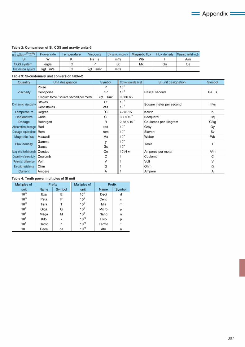
307
Appendix
Magnetic field strength
A/m
Oe
―
Flux density
T
Gs
―
Magnetic flux
Wb
Mx
―
Dynamic viscosity
m2/s
St
m2/s
Viscosity
Pa・s
P
kgf・s/m2
Temperature
K
°C
°C
Power rate
W
erg/s
kgf・m/s
SI
CGS system
Gravitation system
Unit systemQuantity
Symbol
Pa・s
m2/s
K
Bq
C/kg
Gy
Sv
Wb
T
A/m
C
V
Ω
A
SI unit designationSymbol
P
cP
kgf・s/m2
St
cSt
˚C
Ci
R
rad
rem
Mx
γ
Gs
Oe
C
V
Ω
A
Unit designationQuantity
Viscosity
Dynamic viscosity
Temperature
Radioactive
Dosage
Absorption dosage
Dosage equivalent
Magnetic flux
Flux density
Magnetic field strength
Quantity of electricity
Potential difference
Electric resistance
Current
Conversion rate to SI
Pascal second
Square meter per second
Kelvin
Becquerel
Coulombs per kilogram
Gray
Sievert
Weber
Tesla
Amperes per meter
Coulomb
Volt
Ohm
Ampere
10-1
10-3
9.806 65
10-4
10-6
+273.15
3.7×10¹⁰
2.58×10⁻⁴
10-2
10-2
10-8
10-9
10-4
103/4π
1
1
1
1
Poise
Centipoise
Kilogram force / square second per meter
Stokes
Centistokes
Degree
Curie
Roentgen
Rad
Rem
Maxwell
Gamma
Gauss
Oersted
Coulomb
Volt
Ohm
Ampere
PrefixMultiples of
unit
1018
1015
1012
109
106
103
102
10
Name
Exa
Peta
Tera
Giga
Mega
Kilo
Hecto
Deca
Symbol
E
P
T
G
M
k
h
da
PrefixMultiples of
unit
10-1
10-2
10-3
10-6
10-9
10-12
10-15
10-18
Name
Deci
Centi
Mili
Micro
Nano
Pico
Femto
Ato
Symbol
d
c
m
μ
n
p
f
a
Table 3: SI-customary unit conversion table-2
Table 4: Tenth power multiples of SI unit
Table 2: Comparison of SI, CGS and gravity units-2
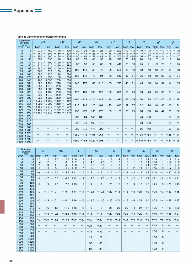
308
Appendix
Diameter division
mmover incl. high low high lowhigh lowhigh lowhigh low high low high lowhigh lowhigh low
a13 c12 d6 e6 e13 f5 f6 g5 g6
3 6
10 1830 4050 6580
100120 140 160180 200 225250 280315 355400 450500 560630 710800 900
1 000 1 1201 250 1 400
- 30 - 40 - 50 - 65
- 80
-100
-120
-190
-210
-230
-260
-290
-320
-350
-390
-145
-170
- 38 - 49 - 61 - 78
- 96
-119
-142
-222
-246
-270
-304
-340
-376
-416
-468
-170
-199
- 20 - 25 - 32 - 40
- 50
- 60
- 72
-110
-125
-135
-145
-160
-170
-195
-220
- 85
-100
- 28 - 34 - 43 - 53
- 66
- 79
- 94
-142
-161
-175
-189
-210
-226
-261
-298
-110
-129
6 10 18 3040 5065 80
100 120140 160 180200 225 250280 315355 400450 500560 630710 800900
1 0001 120 1 2501 400 1 600
- 270 - 280 - 290 - 300- 310 - 320- 340 - 360- 380 - 410- 460 - 520 - 580- 660 - 740 - 820- 920 -1 050-1 200 -1 350-1 500 -1 650
-
-
-
-
-
- 450 - 500 - 560 - 630- 700 - 710- 800 - 820- 920 - 950-1 090 -1 150 -1 210-1 380 -1 460 -1 540-1 730 -1 860-2 090 -2 240-2 470 -2 620
-
-
-
-
-
- 70 - 80 - 95 -110-120 -130-140 -150-170 -180-200 -210 -230-240 -260 -280-300 -330-360 -400-440 -480
-
-
-
-
-
- 190 - 230 - 275 - 320- 370 - 380- 440 - 450- 520 - 530- 600 - 610 - 630- 700 - 720 - 740- 820 - 850- 930 - 970-1 070 -1 110
-
-
-
-
-
- 20 - 25 - 32 - 40
- 50
- 60
- 72
-110
-125
-135
- 85
-100
-
-
-
-
-
- 200 - 245 - 302 - 370
- 440
- 520
- 612
- 920
-1 015
-1 105
- 715
- 820
-
-
-
-
-
-10 -13 -16 -20
-25
-30
-36
-56
-62
-68
-43
-50
-
-
-
-
-
-15 -19 -24 -29
-36
-43
-51
-79
-87
-95
-61
-70
-
-
-
-
-
- 4 - 5 - 6 - 7
- 9
-10
-12
-17
-18
-20
-14
-15
-
-
-
-
-
- 4 - 5 - 6 - 7
- 9
-10
-12
-17
-18
-20
-22
-24
-26
-28
-30
-14
-15
- 12 - 14 - 17 - 20
- 25
- 29
- 34
- 49
- 54
- 60
- 66
- 74
- 82
- 94
-108
- 39
- 44
- 9 -11 -14 -16
-20
-23
-27
-40
-43
-47
-32
-35
-
-
-
-
-
- 10 - 13 - 16 - 20
- 25
- 30
- 36
- 56
- 62
- 68
- 76
- 80
- 86
- 98
-110
- 43
- 50
- 18 - 22 - 27 - 33
- 41
- 49
- 58
- 88
- 98
-108
-120
-130
-142
-164
-188
- 68
- 79
Diameter division
mmover incl. high low high lowhigh lowhigh lowhigh low high low high lowhigh lowhigh low
j5 js5 j6 js6 j7 k4 k5 k6 m5
3 6
10 1830 4050 6580
100120 140 160180 200 225250 280315 355400 450500 560630 710800 900
1 000 1 1201 250 1 400
6 10 18 3040 5065 80
100 120140 160 180200 225 250280 315355 400450 500560 630710 800900
1 0001 120 1 2501 400 1 600
+3 +4 +5 +5
-
-
-
-
-
+6
+6
+6
+7
+7
+7
+7
+7
- 5
ー 7
ー 9
-16
-18
-20
-11
-13
- 2 - 2 - 3 - 4
-
-
-
-
-
+ 5.5
+ 6.5
+ 7.5
+11.5
+12.5
+13.5
+ 9
+10
+ 2.5 + 3 + 4 + 4.5
-
-
-
-
-
- 5.5
- 6.5
- 7.5
-11.5
-12.5
-13.5
- 9
-10
- 2.5 - 3 - 4 - 4.5
-
-
-
-
-
+ 8
+ 9.5
+11
+16
+18
+20
+12.5
+14.5
+ 4 + 4.5 + 5.5 + 6.5
+22
+25
+28
+33
+39
- 8
- 9.5
-11
-16
-18
-20
-12.5
-14.5
- 4 - 4.5 - 5.5 - 6.5
-22
-25
-28
-33
-39
-
-
-
-
-
+11
+12
+13
+16
+18
+20
+14
+16
+ 6 + 7 + 8 + 9
+15
+18
+20
+26
+29
+31
+22
+25
+ 8 +10 +12 +13
-
-
-
-
-
ー10
ー12
ー15
-26
-28
ー32
ー18
-21
- 4 - 5 - 6 ー 8
-
-
-
-
-
+ 9
+10
+13
+20
+22
+25
+15
+18
+ 5 + 5 + 6 + 8
-
-
-
-
-
+2
+2
+3
+4
+4
+5
+3
+4
+1 +1 +1 +2
-
-
-
-
-
+18
+21
+25
+36
+40
+45
+44
+50
+56
+66
+78
+28
+33
+ 9 +10 +12 +15
+2
+2
+3
+4
+4
+5
0
0
0
0
0
+3
+4
+1 +1 +1 +2
+13
+15
+18
+27
+29
+32
+21
+24
+ 6 + 7 + 9 +11
-
-
-
-
-
+20
+24
+28
+43
+46
+50
+33
+37
+ 9 +12 +15 +17
-
-
-
-
-
+ 9
+11
+13
+20
+21
+23
+15
+17
+ 4 + 6 + 7 + 8
-
-
-
-
-
-
-
-
-
-
+2
+2
+3
+4
+4
+5
+3
+4
+1 +1 +1 +2
-
-
-
-
-
- 5
- 7
- 9
-16
-18
-20
-11
-13
- 2 - 2 - 3 - 4
Table 5: Dimensional tolerance for shafts
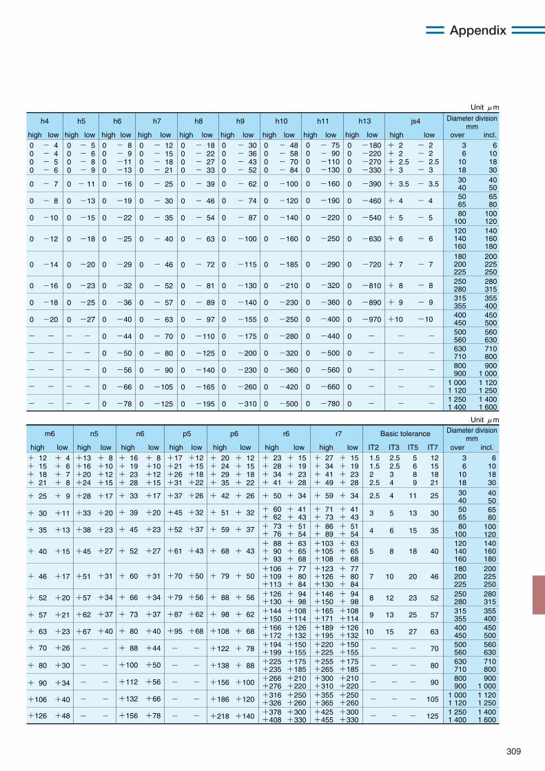
309
Appendix
over incl.high low high lowhigh lowhigh lowhigh low high low high lowhigh lowhigh low
h5h4 h6 h7 h8 h9 h10 h11 js4
0 0 0 0
0
0
0
0
0
0
0
0
0
0
0
0
0
- 12 - 15 - 18 - 21
- 25
- 30
- 35
- 52
- 57
- 63
- 70
- 80
- 90
-105
-125
- 40
- 46
0 0 0 0
0
0
0
0
0
0
0
0
0
0
0
0
0
- 18 - 22 - 27 - 33
- 39
- 46
- 54
- 81
- 89
- 97
-110
-125
-140
-165
-195
- 63
- 72
-12
0 0 0 0
0
0
0
0
0
0
0
0
-
-
-
-
-
- 4 - 4 - 5 - 6
- 7
- 8
-10
-14
-16
-18
-20
-
-
-
-
-
0 0 0 0
0
0
0
0
0
0
0
0
-
-
-
-
-
- 5 - 6 - 8 - 9
- 11
-13
-15
-18
-20
-23
-25
-27
-
-
-
-
-
0 0 0 0
0
0
0
0
0
0
0
0
0
0
0
0
0
- 8 - 9 -11 -13
-16
-19
-22
-25
-29
-32
-36
-40
-44
-50
-56
-66
-78
0 0 0 0
0
0
0
0
0
0
0
0
0
0
0
0
0
- 30 - 36 - 43 - 52
- 62
- 74
- 87
-130
-140
-155
-175
-200
-230
-260
-310
-100
-115
0 0 0 0
0
0
0
0
0
0
0
0
0
0
0
0
0
- 48 - 58 - 70 - 84
-100
-120
-140
-210
-230
-250
-280
-320
-360
-420
-500
-160
-185
+ 2 + 2 + 2.5 + 3
+ 3.5
+ 4
+ 5
- 3.5
- 4
- 5
+ 8
+ 9
+10
+ 6
+ 7
-
-
-
-
-
6 10 18 3040 5065 80
100 120140 160 180200 225 250280 315355 400450 500560 630710 800900
1 0001 120 1 250
3 6
10 1830 40
120 140 160
50 6580
100
180 200 225250 280315 355400 450500 560630 710800 900
1 000 1 1201 250 1 400
1 400 1 600
- 2 - 2 - 2.5 - 3
- 8
- 9
-10
- 6
- 7
-
-
-
-
-
0 0 0 0
0
0
0
0
0
0
0
0
0
0
0
0
0
- 75 - 90 -110 -130
-160
-190
-220
-320
-360
-400
-440
-500
-560
-660
-780
-250
-290
high low
h13
0 0 0 0
0
0
0
0
0
0
0
0
0
0
0
0
0
-
-
-
-
-
-180 -220 -270 -330
-390
-460
-540
-810
-890
-970
-630
-720
Diameter division mm
over incl.highhigh lowlow high lowhigh lowhigh lowhigh low high low IT5 IT7IT2 IT3
n5m6 n6 p5 p6 r6 r7 Basic tolerance
+ 12 + 15 + 18 + 21
+ 25
+ 30
+ 35
+ 40
+ 46
+ 52
+ 57
+ 63
+ 70
+ 80
+ 90
+106
+126
+ 4 + 6 + 7 + 8
+ 9
+11
+13
+15
+17
+20
+21
+23
+26
+30
+34
+40
+48
+13 +16 +20 +24
-
-
-
-
-
+28
+33
+38
+57
+62
+67
+45
+51
+17
+20
+23
+34
+37
+40
+27
+31
+ 8 +10 +12 +15
-
-
-
-
-
+ 33
+ 39
+ 45
+ 66
+ 73
+ 80
+ 88
+100
+112
+132
+156
+ 52
+ 60
+ 16 + 19 + 23 + 28
+17
+20
+23
+34
+37
+40
+44
+50
+56
+66
+78
+27
+31
+ 8 +10 +12 +15
+ 42
+ 51
+ 59
+ 88
+ 98
+108
+ 68
+ 79
+ 20 + 24 + 29 + 35
+122
+138
+156
+186
+218
+ 26
+ 32
+ 37
+ 56
+ 62
+ 68
+ 43
+ 50
+ 12 + 15 + 18 + 22
+ 78
+ 88
+100
+120
+140
-
-
-
-
-
+37
+45
+52
+79
+87
+95
+61
+70
+17 +21 +26 +31
+ 50
+ 88 + 90 + 93
+ 63 + 65 + 68
+106 +109 +113
+ 77 + 80 + 84
+103 +105 +108+123 +126 +130
+ 63 + 65 + 68
120 140 160
+ 77 + 80 + 84
180 200 225
140 160 180200 225 250
+ 23 + 28 + 34 + 41
+ 34
+ 15 + 19 + 23 + 28
+ 59
+ 27 + 34 + 41 + 49
+ 34
+ 15 + 19 + 23 + 28
25
30
35
52
57
63
70
80
90
105
125
40
46
12 15 18 21
2.5
3
4
8
9
10
5
7
1.5 1.5 2 2.5
-
-
-
-
-
3 6
10 18
6 10 18 30
11
13
15
23
25
27
18
20
5 6 8 9
-
-
-
-
-
-
-
-
-
-
4
5
6
12
13
15
8
10
2.5 2.5 3 4
-
-
-
-
-
+26
+32
+37
+56
+62
+68
+43
+50
+12 +15 +18 +22
Diameter division mm
Unit μm
Unit μm
+ 60 + 62+ 73 + 76
+ 41 + 43+ 51 + 54
+ 71 + 73+ 86 + 89
+ 41 + 43+ 51 + 54
50 65
30 40
80 100
65 80
40 50
100 120
+126 +130+144 +150+166 +172
+ 94 + 98+108 +114+126 +132
+146 +150+165 +171+189 +195
+ 94 + 98+108 +114+126 +132
250 280315 355400 450
280 315355 400450 500
+194 +199+225 +235+266 +276+316 +326+378 +408
+150 +155+175 +185+210 +220+250 +260+300 +330
+220 +225+255 +265+300 +310+355 +365+425 +455
+150 +155+175 +185+210 +220+250 +260+300 +330
500 560630 710800 900
1 000 1 1201 250 1 400
560 630710 800900
1 0001 120 1 2501 400 1 600
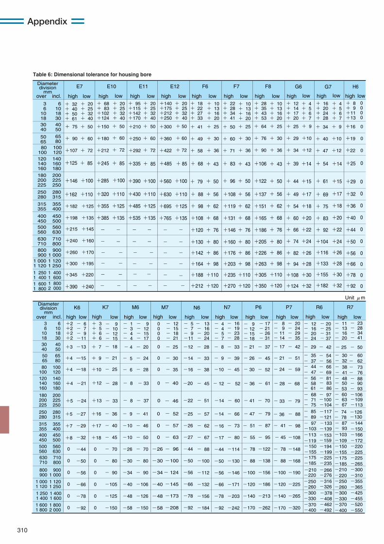
310
Appendix
Diameter division
mmover incl. high low high lowhigh lowhigh lowhigh low high low highhigh low lowhigh lowhigh low
E7 E10 E11 E12 F6 F7 F8 G6 G7
3 6
10 1830 40
50 6580
100120 140 160
180 200 225
250 280
315 355
400 450500 560
630 710800 900
1 000 1 120
1 250 1 400
+140 +175 +212 +250
+300
+360
+422
+630
+695
+765
-
-
-
-
-
+485
+560
+ 20 + 25 + 32 + 40
+ 50
+ 60
+ 72
+110
+125
+135
-
-
-
-
-
+ 85
+100
+ 8 + 9 +11 +13
+16
+19
+22
+32
+36
+40
+44
+50
+56
+66
+78
+92
+25
+29
+ 18 + 22 + 27 + 33
+ 41
+ 49
+ 58
+ 88
+ 98
+108
+120
+130
+142
+164
+188
+212
+ 68
+ 79
+ 10 + 13 + 16 + 20
+ 25
+ 30
+ 36
+ 56
+ 62
+ 68
+ 76
+ 80
+ 86
+ 98
+110
+120
+ 43
+ 50
+ 22 + 28 + 34 + 41
+ 50
+ 60
+ 71
+108
+119
+131
+146
+160
+176
+203
+235
+270
+ 83
+ 96
+ 10 + 13 + 16 + 20
+ 25
+ 30
+ 36
+ 56
+ 62
+ 68
+ 76
+ 80
+ 86
+ 98
+110
+120
+ 43
+ 50
+ 28 + 35 + 43 + 53
+ 64
+ 76
+ 90
+137
+151
+165
+186
+205
+226
+263
+305
+350
+106
+122
+ 10 + 13 + 16 + 20
+ 25
+ 30
+ 36
+ 56
+ 62
+ 68
+ 76
+ 80
+ 86
+ 98
+110
+120
+ 43
+ 50
+ 12 + 14 + 17 + 20
+ 25
+ 29
+ 34
+ 49
+ 54
+ 60
+ 66
+ 74
+ 82
+ 94
+108
+124
+ 39
+ 44
+ 4 + 5 + 6 + 7
+ 9
+10
+12
+17
+18
+20
+22
+24
+26
+28
+30
+32
+14
+15
+ 16 + 20 + 24 + 28
+ 34
+ 40
+ 47
+ 69
+ 75
+ 83
+ 92
+104
+116
+133
+155
+182
+ 54
+ 61
+ 4 + 5 + 6 + 7
+ 9
+10
+12
+17
+18
+20
+22
+24
+26
+28
+30
+32
+14
+15
0 0 0 0
0
0
0
0
0
0
0
0
0
0
0
0
0
0
+ 95 +115 +142 +170
+210
+250
+292
+430
+485
+535
-
-
+335
+390
+ 20 + 25 + 32 + 40
+ 50
+ 60
+ 72
+110
+125
+135
-
-
+ 85
+100
+ 32 + 40 + 50 + 61
+ 75
+ 90
+107
+162
+125
+146
+ 20 + 25 + 32 + 40
+ 50
+ 60
+ 72
+110
+ 85
+100
+ 68 + 83
+102 +124
+150
+180
+212
+320
+355
+385
-
-
+245
+285
+ 20 + 25 + 32 + 40
+ 50
+ 60
+ 72
+110
+125
+135
-
-
+ 85
+100
6 10 18 3040 50
65 80
100 120140 160 180
200 225 250
280 315
355 400
450 500560 630
710 800900
1 0001 120 1 250
1 400 1 600
Diameter division
mmover incl. high low high lowhigh lowhigh lowhigh low high low highhigh lowlowhigh lowhigh low
K6 K7 M6 M7 N7 P6 P7 R6 R7
3 6
10 1830 4050 6580
100120 140 160
180 200 225
250 280
315 355400 450500 560630 710
800 900
1 000 1 120
1 600 1 800
6 10 18 3040 5065 80
100 120140 160 180
200 225 250
280 315
355 400450 500560 630710 800
900 1 000
1 120 1 250
1 800 2 000
1 250 1 400
1 400 1 600
+2 +2 +2 +2
0
0
0
0
0
0
+3
+4
+4
+5
+7
+8
+4
+5
-13
ー15
ー18
-27
-29
-32
-44
-50
-56
-66
-78
-92
-21
-24
- 6 - 7 - 9 -11
+ 7
+ 9
+10
+16
+17
+18
+12
+13
+ 3 + 5 + 6 + 6
0
0
0
0
0
0
- 18
- 21
- 25
- 36
- 40
- 45
- 70
- 80
- 90
-105
-125
-150
- 28
- 33
- 9 - 10 - 12 - 15
- 4
- 5
- 6
- 9
-10
-10
-26
-30
-34
-40
-48
-58
- 8
- 8
- 1 - 3 - 4 - 4
- 12 - 16 - 20 - 24
- 20 - 25 - 31 - 37
- 11 - 13 - 16 - 20
- 23 - 28 - 34 - 41
- 20
- 24
- 28
- 41
- 46
- 50
- 70
- 80
- 90
-106
-126
-150
- 33
- 37
- 9 - 12 - 15 - 17
0
0
0
-26
-30
-34
-40
-48
-58
- 25
- 30
- 35
- 52
- 57
- 63
- 96
-100
- 124
-145
-173
-208
- 40
- 46
- 12 - 15 - 18 - 21
-12
-14
-16
- 21
- 26
- 30
-25
-26
-27
-44
-50
-56
-66
-78
-92
-20
-22
- 5 - 7 - 9 -11
- 28
- 33
- 38
- 57
- 62
- 67
- 88
-100
-112
-132
-156
-184
- 66
- 73
- 80
-114
-130
-146
-171
-203
-242
- 45
- 51 -14 - 60 - 41 - 70
- 13 - 16 - 20 - 24
- 8
- 9
-10
-16
-17
-44
-50
-56
-66
-78
-92
- 36
- 4 - 4 - 5 - 7
- 33
- 39
- 45
- 37
- 45
- 52
- 61- 12 - 52
- 16 - 19 - 23 - 28
- 9 - 12 - 15 - 18
- 17 - 21 - 26 - 31
H6
+182 +125
+198 +135
+215 +145
+240 +160
+260 +170
+300 +195
+345 +220
- -
- -
- -
- -
- -
- -
- - - - - - 1 600 1 800
1 800 2 000 +390 +240
0 0 0 0
0
0
0
0
0
-14 - 79
- 87
- 95
-122
-138
-156
-186
-213
-262
- 51
- 55
- 78
- 88
-100
-120
-140
-170
- 47
- 17
- 21
- 24
- 33 - 79
- 28
- 42
- 51
- 59
- 25 - 50
- 29 - 42
- 35 - 54 - 37 - 56
- 30 - 60 - 32 - 62
- 48 - 88 - 50 - 90
- 53 - 93- 60 -106
- 63 -109- 67 -113
- 38 - 73 - 41 - 76
- 44 - 66 - 47 - 69
- 56 - 81
- 61 - 86
- 58 - 83
- 68 - 97 - 71 -100 - 75 -104
- 85 -117 - 89 -121
- 74 -126 -130- 78
-103-109 -150 -155 -175 -185 -210 -220 -250 -260 -300 -330 -370 -400
- 87 -144 -150 -166 -172 -220 -225 -225 -265 -300 -310 -355 -365 -425 -455 -520 -550
- 93- 97 -133
-103 -139
-150 -194 -155 -199 -175 -225
-185 -235 -210 -266 -220 -276
-250 -316 -260 -326 -300 -378 -330 -408 -370 -462 -400 -492
-113 -153 -119 -159
- 68
- 8 - 9 - 11 - 14
- 20 - 24 - 29 - 35
- 88
- 98
-108
-148
-168
-190
-225
-265
-320
- 41
- 45
- 78
- 88
-100
-120
-140
-170
- 36
N6
Unit μm
Table 6: Dimensional tolerance for housing bore
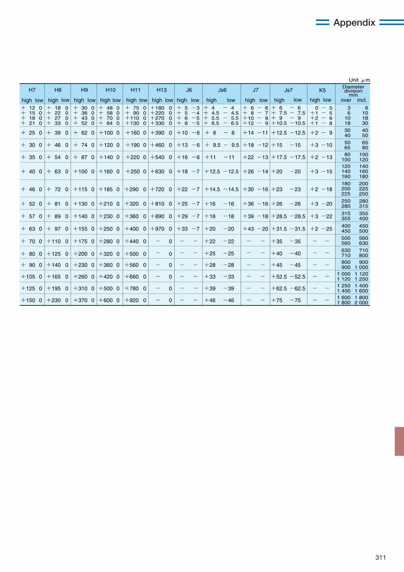
311
Appendix
high low high lowhigh lowhigh lowhigh low high high highlow low low highhigh low lowhigh low
H7 H8 H9 H10 H11 H13 J6 Js6 J7 Js7 K5
30 40
50 6580
100120 140 160
180 200 225
250 280
315 355
400 450500 560
630 710800 900
1 000 1 1201 250 1 4001 600 1 800
40 50
65 80
100 120140 160 180
200 225 250
280 315
355 400
450 500560 630
710 800900
1 0001 120 1 2501 400 1 6001 800 2 000
Unit μm
+ 4 + 4.5 + 5.5 + 6.5
- 4 - 4.5 - 5.5 - 6.5
+ 6 + 7.5 + 9 +10.5
- 6 - 7.5 - 9 -10.5
3 6
10 18
6 10 18 30
+ 18 + 22 + 27 + 33
+ 12 + 15 + 18 + 21
+ 30 + 36 + 43 + 52
+ 48 + 58 + 70 + 84
+ 75 + 90 +110 +130
0 0 0 0
0 0 0 0
0 0 0 0
0 0 0 0
0 0 0 0
0 0 0 0
+180 +220 +270 +330
+ 5 + 5 + 6 + 8
-3 -4 -5 -5
+ 6 + 8 +10 +12
- 6 - 7 - 8 - 9
0 +1 +2 +1
- 5 - 5 - 6 - 8
+ 8
+ 9.5
+11
- 8
- 9.5
-11
+12.5
+15
+17.5
-12.5
-15
-17.5
+ 39
+ 46
+ 54
+ 25
+ 30
+ 35
+ 62
+ 74
+ 87
+100
+120
+140
+160
+190
+220
0
0
0
0
0
0
0
0
0
0
0
0
0
0
0
0
0
0
+390
+460
+540
+10
+13
+16
-6
-6
-6
+14
+18
+22
-11
-12
-13
+2
+3
+2
- 9
-10
-13
+16
+18
+20
+22
+25
-16
-18
-20
-22
-25
+26
+28.5
+31.5
+35
+40
-26
-28.5
-31.5
-35
-40
+ 81
+ 89
+ 97
+110
+125
+ 52
+ 57
+ 63
+ 70
+ 80
+130
+140
+155
+175
+200
+210
+230
+250
+280
+320
+320
+360
+400
+440
+500
0
0
0
0
0
0
0
0
0
0
0
0
0
0
0
0
0
0
0
0
0
0
0
0
0
0
0
0
0
0
+810
+890
+970
+25
+29
+33
-7
-7
-7
+36
+39
+43
-16
-18
-20
+3
+3
+2
-20
-22
-25
+12.5 -12.5 +20 -20 + 63+ 40 +100 +160 +2500 0 0 0 0 0+630 +18 -7 +26 -14 +3 -15
+14.5 -14.5 +23 -23 + 72+ 46 +115 +185 +2900 0 0 0 0 0+720 +22 -7 +30 -16 +2 -18
-
-
-
-
-
-
-
-
-
-
-
-
-
-
Diameter division
mmover incl.
+140+ 90 +230 +360 +5600 0 0 0 0 0 +28 -28 +45 - - - - - - - -45
+165+105 +260 +420 +6600 0 0 0 0 0 +33 -33 +52.5- - - - - - - -52.5
+195+125 +310 +500 +7800 0 0 0 0 0 +39 -39 +62.5- - - - - - - -62.5
+230+150 +370 +600 +9200 0 0 0 0 0 +46 -46 +75 - - - - - - - -75
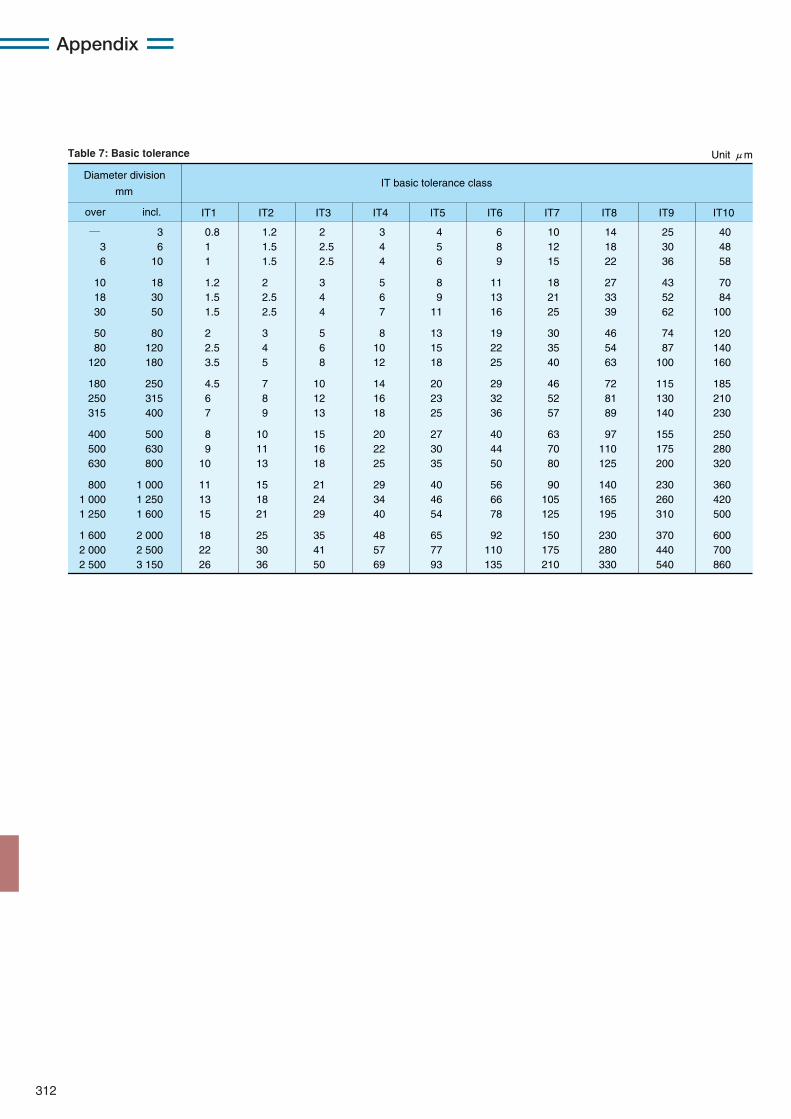
312
Appendix
IT1 IT2 IT3 IT4 IT5 IT6 IT7 IT8 IT9 IT10
Unit μm
IT basic tolerance classmm
over incl.
― 3 6
10 18 30
50 80
120
180 250 315
400 500 630
800 1 000 1 250
1 600 2 000 2 500
3 6
10
18 30 50
80 120 180
250 315 400
500 630 800
1 000 1 250 1 600
2 000 2 500 3 150
0.8 1 1
1.2 1.5 1.5
2 2.5 3.5
4.5 6 7
8 9 10
11 13 15
18 22 26
1.2 1.5 1.5
2 2.5 2.5
3 4 5
7 8 9
10 11 13
15 18 21
25 30 36
2 2.5 2.5
3 4 4
5 6 8
10 12 13
15 16 18
21 24 29
35 41 50
3 4 4
5 6 7
8 10 12
14 16 18
20 22 25
29 34 40
48 57 69
4 5 6
8 9
11
13 15 18
20 23 25
27 30 35
40 46 54
65 77 93
6 8 9
11 13 16
19 22 25
29 32 36
40 44 50
56 66 78
92 110 135
10 12 15
18 21 25
30 35 40
46 52 57
63 70 80
90 105 125
150 175 210
14 18 22
27 33 39
46 54 63
72 81 89
97 110 125
140 165 195
230 280 330
25 30 36
43 52 62
74 87
100
115 130 140
155 175 200
230 260 310
370 440 540
40 48 58
70 84
100
120 140 160
185 210 230
250 280 320
360 420 500
600 700 860
Diameter division
Table 7: Basic tolerance
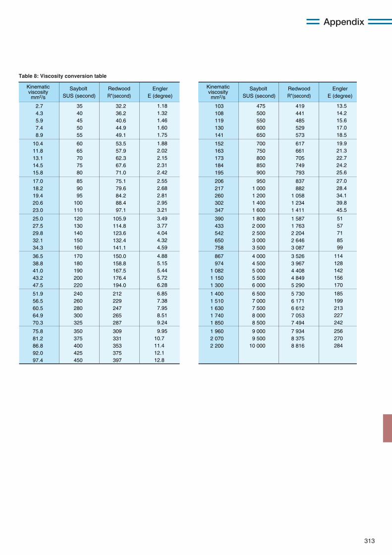
313
Appendix
Kinematic viscosity mm2/s
2.7 4.3 5.9 7.4 8.9
10.4 11.8 13.1 14.5 15.8
17.0 18.2 19.4 20.6 23.0
25.0 27.5 29.8 32.1 34.3
36.5 38.8 41.0 43.2 47.5
51.9 56.5 60.5 64.9 70.3
75.8 81.2 86.8 92.0 97.4
32.2 36.2 40.6 44.9 49.1
53.5 57.9 62.3 67.6 71.0
75.1 79.6 84.2 88.4 97.1
105.9 114.8 123.6 132.4 141.1
150.0 158.8 167.5 176.4 194.0
212 229 247 265 287
309 331 353 375 397
1.18 1.32 1.46 1.60 1.75
1.88 2.02 2.15 2.31 2.42
2.55 2.68 2.81 2.95 3.21
3.49 3.77 4.04 4.32 4.59
4.88 5.15 5.44 5.72 6.28
6.85 7.38 7.95 8.51 9.24
9.95 10.7 11.4 12.1 12.8
35 40 45 50 55
60 65 70 75 80
85 90 95
100 110
120 130 140 150 160
170 180 190 200 220
240 260 280 300 325
350 375 400 425 450
Saybolt SUS (second)
Redwood R"(second)
Engler E (degree)
Kinematic viscosity mm2/s
Saybolt SUS (second)
Redwood R"(second)
Engler E (degree)
103 108 119 130 141
152 163 173 184 195
206 217 260 302 347
390 433 542 650 758
867 974
1 082 1 150 1 300
1 400 1 510 1 630 1 740 1 850
1 960 2 070 2 200
419 441 485 529 573
617 661 705 749 793
837 882
1 058 1 234 1 411
1 587 1 763 2 204 2 646 3 087
3 526 3 967 4 408 4 849 5 290
5 730 6 171 6 612 7 053 7 494
7 934 8 375 8 816
13.5 14.2 15.6 17.0 18.5
19.9 21.3 22.7 24.2 25.6
27.0 28.4 34.1 39.8 45.5
51 57 71 85 99
114 128 142 156 170
185 199 213 227 242
256 270 284
475 500 550 600 650
700 750 800 850 900
950 1 000 1 200 1 400 1 600
1 800 2 000 2 500 3 000 3 500
4 000 4 500 5 000 5 500 6 000
6 500 7 000 7 500 8 000 8 500
9 000 9 500
10 000
Table 8: Viscosity conversion table

314
Appendix
0.1020 0.2039 0.3059 0.4079 0.5099
0.6118 0.7138 0.8158 0.9177 1.0197
1.1217 1.2237 1.3256 1.4276 1.5296
1.6316 1.7335 1.8355 1.9375 2.0394
2.1414 2.2434 2.3454 2.4473 2.5493
2.6513 2.7532 2.8552 2.9572 3.0592
3.1611 3.2631 3.3651
9.8066 19.613 29.420 39.227 49.033
58.840 68.646 78.453 88.260 98.066
107.87 117.68 127.49 137.29 147.10
156.91 166.71 176.52 186.33 196.13
205.94 215.75 225.55 235.36 245.17
254.97 264.78 274.59 284.39 294.20
304.01 313.81 323.62
1 2 3 4 5
6 7 8 9 10
11 12 13 14 15
16 17 18 19 20
21 22 23 24 25
26 27 28 29 30
31 32 33
3.4670 3.5690 3.6710 3.7730 3.8749
3.9769 4.0789 4.1808 4.2828 4.3848
4.4868 4.5887 4.6907 4.7927 4.8946
4.9966 5.0986 5.2006 5.3025 5.4045
5.5065 5.6085 5.7104 5.8124 5.9144
6.0163 6.1183 6.2203 6.3223 6.4242
6.5262 6.6282 6.7302
333.43 343.23 353.04 362.85 372.65
382.46 392.27 402.07 411.88 421.68
431.49 441.30 451.10 460.91 470.72
480.52 490.33 500.14 509.94 519.75
529.56 539.36 549.17 558.98 568.78
578.59 588.40 598.20 608.01 617.82
627.62 637.43 647.24
34 35 36 37 38
39 40 41 42 43
44 45 46 47 48
49 50 51 52 53
54 55 56 57 58
59 60 61 62 63
64 65 66
kgf N kgf N
6.8321 6.9341 7.0361 7.1380 7.2400
7.3420 7.4440 7.5459 7.6479 7.7499
7.8518 7.9538 8.0558 8.1578 8.2597
8.3617 8.4637 8.5656 8.6676 8.7696
8.8716 8.9735 9.0755 9.1775 9.2794
9.3814 9.4834 9.5854 9.6873 9.7893
9.8913 9.9932
10.0952
657.04 666.85 676.66 686.46 696.27
706.08 715.88 725.69 735.50 745.30
755.11 764.92 774.72 784.53 794.34
804.14 813.95 823.76 833.56 843.37
853.18 862.98 872.79 882.60 892.40
902.21 912.02 921.82 931.63 941.44
951.24 961.05 970.86
67 68 69 70 71
72 73 74 75 76
77 78 79 80 81
82 83 84 85 86
87 88 89 90 91
92 93 94 95 96
97 98 99
kgf N
1kgf=9.80665N 1N=0.101972kgf
If for example you want to convert 10 kgf to N, find "10" in the middle column of the first set of columns on the right. Look in the N column directly to the right of "10," and you will see that 10 kgf equals 98.066 N. Oppositely, to convert 10 N to kgf, look in the kgf column to the right of "10" and you will see that 10 N equals 1.0197 kgf.
〔How to read the table〕
Table 9: Kgf to N conversion table

315
Appendix
1/64 1/32 3/64 1/16 5/64 3/32 7/64 1/ 8 9/64 5/32
11/64 3/16
13/64 7/32
15/64 1/ 4 17/64 9/32
19/64 5/16
21/64 11/32 23/64 3/ 8
25/64 13/32 27/64 7/16
29/64 15/32 31/64 1/ 2
33/64 17/32 35/64 9/16
37/64 19/32 39/64 5/ 8
41/64 21/32 43/64 11/16 45/64 23/32 47/64 3/ 4
49/64 25/32 51/64 13/16 53/64 27/32 55/64 7/ 8
57/64 39/32 59/64 15/16 61/64 31/32 63/64
0.015625 0.031250 0.046875 0.062500 0.078125 0.093750 0.109375 0.125000 0.140625 0.156250 0.171875 0.187500 0.203125 0.218750 0.234375 0.250000 0.265625 0.281250 0.296875 0.312500 0.328125 0.343750 0.359375 0.375000 0.390625 0.406250 0.421875 0.437500 0.453125 0.468750 0.484375 0.500000 0.515625 0.531250 0.546875 0.562500 0.578125 0.593750 0.609375 0.625000 0.640625 0.656250 0.671875 0.687500 0.703125 0.718750 0.734375 0.750000 0.765625 0.781250 0.796875 0.812500 0.828125 0.843750 0.859375 0.875000 0.890625 0.906250 0.921875 0.937500 0.953125 0.968750 0.984375
0.397 0.794 1.191 1.588 1.984 2.381 2.778 3.175 3.572 3.969 4.366 4.762 5.159 5.556 5.953 6.350 6.747 7.144 7.541 7.938 8.334 8.731 9.128 9.525 9.922
10.319 10.716 11.112 11.509 11.906 12.303 12.700 13.097 13.494 13.891 14.288 14.684 15.081 15.478 15.875 16.272 16.669 17.066 17.462 17.859 18.256 18.653 19.050 19.447 19.844 20.241 20.638 21.034 21.431 21.828 22.225 22.622 23.019 23.416 23.812 24.209 24.606 25.003
25.400 25.797 26.194 26.591 26.988 27.384 27.781 28.178 28.575 28.972 29.369 29.766 30.162 30.559 30.956 31.353 31.750 32.147 32.544 32.941 33.338 33.734 34.131 34.528 34.925 35.322 35.719 36.116 36.512 36.909 37.306 37.703 38.100 38.497 38.894 39.291 39.688 40.084 40.481 40.878 41.275 41.672 42.069 42.466 42.862 43.259 43.656 44.053 44.450 44.847 45.244 45.641 46.038 46.434 46.831 47.228 47.625 48.022 48.419 48.816 49.212 49.609 50.006 50.403
50.800 51.197 51.594 51.991 52.388 52.784 53.181 53.578 53.975 54.372 54.769 55.166 55.562 55.959 56.356 56.753 57.150 57.547 57.944 58.341 58.738 59.134 59.531 59.928 60.325 60.722 61.119 61.516 61.912 62.309 62.706 63.103 63.500 63.897 64.294 64.691 65.088 65.484 65.881 66.278 66.675 67.072 67.469 67.866 68.262 68.659 69.056 69.453 69.850 70.247 70.644 71.041 71.438 71.834 72.231 72.628 73.025 73.422 73.819 74.216 74.612 75.009 75406 75.803
76.200 76.597 76.994 77.391 77.788 78.184 48.581 78.978 79.375 79.772 80.169 80.566 80.962 81.359 81.756 82.153 82.550 82.947 83.344 83.741 84.138 84.534 84.931 85.328 85.725 86.122 86.519 86.916 87.312 87.709 88.106 88.503 88.900 89.297 89.694 90.091 90.488 90.884 91.281 91.678 92.075 92.472 92.869 93.266 93.662 94.059 94.456 94.853 95.250 95.647 96.044 96.441 96.838 97.234 97.631 98.028 98.425 98.822 99.219 99.616
100.012 100.409 100.806 101.203
101.600 101.997 102.394 102.791 103.188 103.584 103.981 104.378 104.775 105.172 105.569 105.966 106.362 106.759 107.156 107.553 107.950 108.347 108.744 109.141 109.538 109.934 110.331 110.728 111.125 111.522 111.919 112.316 112.721 113.109 113.506 113.903 114.300 114.697 115.094 115.491 115.888 116.284 116.681 117.078 117.475 117.872 118.269 118.666 119.062 119.459 119.856 120.253 120.650 121.047 121.444 121.841 122.238 122.634 123.031 123.428 123.825 124.222 124.619 125.016 125.412 125.809 126.206 126.603
127.000 127.397 127.794 128.191 128.588 128.984 129.381 129.778 130.175 130.572 130.969 131.366 131.762 132.159 132.556 132.953 133.350 133.747 134.144 134.541 134.938 135.334 135.731 136.128 136.525 136.922 137.319 137.716 138.112 138.509 138.906 139.303 139.700 140.097 140.494 140.891 141.283 141.684 142.081 142.478 142.875 143.272 143.669 144.066 144.462 144.859 145.256 145.653 146.050 146.447 146.844 147.241 147.638 148.034 148.431 148.828 149.225 149.622 150.019 150.416 150.812 151.209 151.606 152.003
152.400 152.797 153.194 153.591 153.988 154.384 154.781 155.178 155.575 155.972 156.369 156.766 157.162 157.559 157.956 158.353 158.750 159.147 159.544 159.941 160.338 160.734 161.131 161.528 161.925 162.322 162.719 163.116 163.512 163.909 164.306 164.703 165.100 165.497 165.894 166.291 166.688 167.084 167.481 167.878 168.275 168.672 169.069 169.466 169.862 170.259 170.656 171.053 171.450 171.847 172.244 172.641 173.038 173.434 173.831 174.228 174.625 175.022 175.419 175.816 176.212 176.609 177.006 177.403
203.200 203.597 203.994 204.391 204.788 205.184 205.581 205.978 206.375 206.772 207.169 207.566 207.962 208.359 208.756 209.153 209.550 209.947 210.344 210.741 211.138 211.534 211.931 212.328 212.725 213.122 213.519 213.916 214.312 214.709 215.106 215.503 215.900 216.297 216.694 217.091 217.488 217.884 218.281 218.678 219.075 219.472 219.869 220.266 220.662 221.056 221.456 221.853 222.250 222.647 223.044 223.441 223.838 224.234 224.631 225.028 225.425 225.822 226.219 226.616 227.012 227.409 227.806 228.203
177.800 178.197 178.594 178.991 179.388 179.784 180.181 180.578 180.975 181.372 181.769 182.166 182.562 182.959 183.356 183.753 184.150 184.547 184.944 185.341 185.738 186.134 186.531 186.928 187.325 187.722 188.119 188.516 188.912 189.309 189.706 190.103 190.500 190.897 191.294 191.691 192.088 192.484 192.881 193.278 193.675 194.072 194.469 194.866 195.262 195.659 196.056 196.453 196.850 197.247 197.644 198.041 198.438 198.834 199.231 199.628 200.025 200.422 200.819 201.216 201.612 202.009 202.406 202.803
228.600 228.997 229.394 229.791 230.188 230.584 230.981 231.378 231.775 232.172 232.569 232.966 233.362 233.759 234.156 234.553 234.950 235.347 235.744 236.141 236.538 236.934 237.331 237.728 238.125 238.522 238.919 239.316 239.712 240.109 240.506 240.903 241.300 241.697 242.094 242.491 242.888 243.284 243.681 244.078 244.475 244.872 245.269 245.666 246.062 246.459 246.856 247.253 247.650 248.047 248.444 248.841 249.238 249.634 250.031 250.428 250.825 251.222 251.619 252.016 252.412 252.809 253.206 253.603
inch
fraction decimal0" 1" 2" 3" 4" 5" 6" 7" 8" 9"
Table 10: Inch-millimetre conversion table
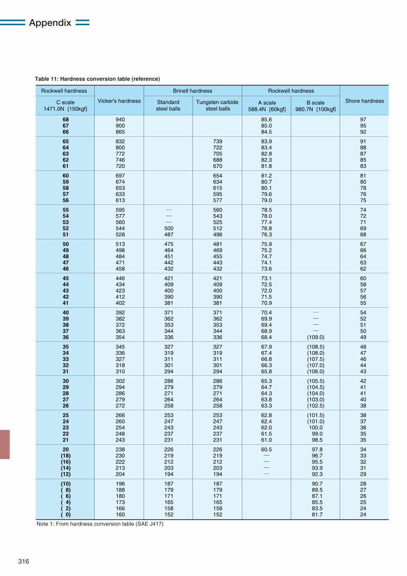
316
Appendix
Rockwell hardness Brinell hardness
Standard steel balls
Vicker's hardness Shore hardnessC scale 1471.0N {150kgf}
A scale 588.4N {60kgf}
B scale 980.7N {100kgf}
Rockwell hardness
Tungsten carbide steel balls
68 67 66
65 64 63 62 61
60 59 58 57 56
55 54 53 52 51
50 49 48 47 46
45 44 43 42 41
40 39 38 37 36
35 34 33 32 31
30 29 28 27 26
25 24 23 22 21
20 (18) (16) (14) (12)
(10) ( 8) ( 6) ( 4) ( 2) ( 0)
940 900 865
832 800 772 746 720
697 674 653 633 613
595 577 560 544 528
513 498 484 471 458
446 434 423 412 402
392 382 372 363 354
345 336 327 318 310
302 294 286 279 272
266 260 254 248 243
238 230 222 213 204
196 188 180 173 166 160
97 95 92
91 88 87 85 83
81 80 78 76 75
74 72 71 69 68
67 66 64 63 62
60 58 57 56 55
54 52 51 50 49
48 47 46 44 43
42 41 41 40 38
38 37 36 35 35
34 33 32 31 29
28 27 26 25 24 24
85.6 85.0 84.5
83.9 83.4 82.8 82.3 81.8
81.2 80.7 80.1 79.6 79.0
78.5 78.0 77.4 76.8 76.3
75.9 75.2 74.7 74.1 73.6
73.1 72.5 72.0 71.5 70.9
70.4 69.9 69.4 68.9 68.4
67.9 67.4 66.8 66.3 65.8
65.3 64.7 64.3 63.8 63.3
62.8 62.4 62.0 61.5 61.0
60.5 ― ― ― ―
― ― ―
500 487
475 464 451 442 432
421 409 400 390 381
371 362 353 344 336
327 319 311 301 294
286 279 271 264 258
253 247 243 237 231
226 219 212 203 194
187 179 171 165 158 152
― ― ― ―
(109.0)
(108.5) (108.0) (107.5) (107.0) (106.0)
(105.5) (104.5) (104.0) (103.0) (102.5)
(101.5) (101.0) 100.0 99.0 98.5
97.8 96.7 95.5 93.9 92.3
90.7 89.5 87.1 85.5 83.5 81.7
739 722 705 688 670
654 634 615 595 577
560 543 525 512 496
481 469 455 443 432
421 409 400 390 381
371 362 353 344 336
327 319 311 301 294
286 279 271 264 258
253 247 243 237 231
226 219 212 203 194
187 179 171 165 158 152
Note 1: From hardness conversion table (SAE J417)
Table 11: Hardness conversion table (reference)
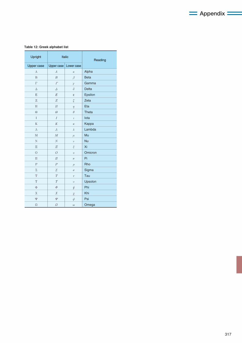
317
Appendix
Upright Italic
Upper case Upper case Lower case
Reading
Alpha
Beta
Gamma
Delta
Epsilon
Zeta
Eta
Theta
Iota
Kappa
Lambda
Mu
Nu
Xi
Omicron
Pi
Rho
Sigma
Tau
Upsolon
Phi
Khi
Psi
Omega
α
β
γ
δ
ε
ζ
η
θ
ι
κ
λ
μ
ν
ξ
ο
π
ρ
σ
τ
υ
φ
χ
ψ
ω
Α
Β
Γ
Δ
Ε
Ζ
Η
Θ
Ι
Κ
Λ
Μ
Ν
Ξ
Ο
Π
Ρ
Σ
Τ
Υ
Φ
Χ
Ψ
Ω
Α
Β
Γ
Δ
Ε
Ζ
Η
Θ
Ι
Κ
Λ
Μ
Ν
Ξ
Ω
Ψ
Χ
Φ
Υ
Τ
Ο
Π
Ρ
Σ
Table 12: Greek alphabet list