precision regulator -...
TRANSCRIPT
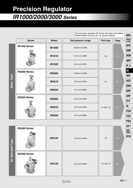
IR1000/2000/3000 Series
Precision Regulator
811
811
811
811
811
Bas
ic T
ype
Air
Op
erat
ed T
ype
Series Set pressure range Page
IR1000 Series0.005 to 0.2 MPa
0.01 to 0.4 MPa
0.01 to 0.8 MPa
1/8
IR2000 Series
IR3000 Series
IR2000 Series
IR3000 Series
Model Port size
IR1000
IR1010
IR1020
0.005 to 0.2 MPa
0.01 to 0.4 MPa
0.01 to 0.8 MPa
1/4
IR2000
IR2010
IR2020
0.01 to 0.2 MPa
0.01 to 0.4 MPa
0.01 to 0.8 MPa
0.01 to 0.8 MPa
1/4, 3/8, 1/2
1/4
IR3000
IR3010
IR3020
IR2120
0.01 to 0.8 MPa 1/4, 3/8, 1/2IR3120
The precision regulator IR series has been remodeled. Please select the new IR-A series instead.
807
ARJAR425to 935
ARX
AMR
ARM
ARP
IR-A
IR
IRV
VEX
SRH
SRP
SRF
ITV
IC
ITVX
ITVH
PVQ
VY1VBAVBAT
AP100
IR
A

OUT OUT OUT OUT OUT
Bracket and pressure gauge can be mounted from 2 directionsMounting is possible on either the front or the back.
Expanded set pressure rangeThe maximum set pressure has been expanded from the current 0.7 MPa to 0.8 MPa.
Compact and lightweightIR1000 width 35 mm weight 140 gIR2000 width 50 mm weight 300 gIR3000 width 66 mm weight 640 g
Manifolding is possible 8 stations at the maximumMade to order specifications (Except IR2120, IR3000 series)
IR1000/2000/3000 SeriesIR1000/2000/3000 Series
Precision Regulator
808
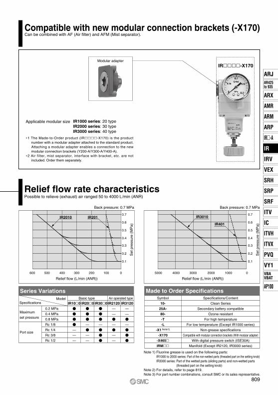
600 500 400 300 200 100 0
0.1
0.2
0.3
0.4
0.5
0.6
0.7IR2010 IR201
5000 4000 3000 2000 1000 0
0.1
0.2
0.3
0.4
0.5
0.6
0.7IR3010
IR401
Compatible with new modular connection brackets (-X170) Can be combined with AF (Air filter) and AFM (Mist separator).
Relief flow rate characteristics
Symbol
10-
25A-
80-
-T
-L
-X1 Note1)
-X170
-X465IRM
Specifications/Content
Clean Series
Secondary battery compatible
Ozone resistant
For high temperature
For low temperature (Except IR1000 series)
Non-grease specifications
Compatible with modular connection brackets (With modular adapter)
With digital pressure switch (ISE30A)
Manifold (Except IR2120, IR3000 series)
Relief flow (L/min (ANR))
Set
pre
ssur
e (M
Pa)
Back pressure: 0.7 MPa
Relief flow (L/min (ANR))
Set
pre
ssur
e (M
Pa)
Back pressure: 0.7 MPa
Model Basic type Air operated typeSpecifications
Maximum
set pressure
Port size
0.2 MPa
0.4 MPa
0.8 MPa
Rc 1/8
Rc 1/4
Rc 3/8
Rc 1/2
—
—
—
—
—
—
—
IR100 IR200—
—
—
—
—
—
—
—
IR2120 IR3120IR300
Made to Order SpecificationsSeries Variations
Possible to relieve (exhaust) air ranged 50 to 4000 L/min (ANR)
Modular adapter
Applicable modular size IR1000 series: 20 typeIR2000 series: 30 typeIR3000 series: 40 type
∗1 The Made-to-Order product (IR-X170) is the product number with a modular adapter attached to the standard product. Attaching a modular adapter enables a connection to the new modular connection brackets (Y200-A/Y300-A/Y400-A).
∗2 Air filter, mist separator, interface with bracket, etc. are not included. Order them separately.
IR-X170
Note 1) Fluorine grease is used on the following parts:IR1000 to 2000 series: Part of the non-wetted parts (threaded part on the setting knob)IR3000 series: Part of the wetted parts (sliding parts) and non-wetted parts
(threaded part on the setting knob)Note 2) For details, refer to page 819.Note 3) For part number combinations, consult SMC or its sales representative.
809
ARJAR425to 935
ARX
AMR
ARM
ARP
IR-A
IR
IRV
VEX
SRH
SRP
SRF
ITV
IC
ITVX
ITVH
PVQ
VY1VBAVBAT
AP100
IR
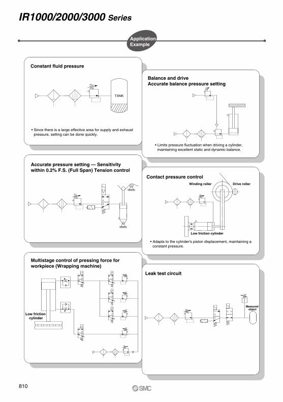
Application Example
Constant fluid pressure
Balance and driveAccurate balance pressure setting
Accurate pressure setting — Sensitivity within 0.2% F.S. (Full Span) Tension control
Multistage control of pressing force for workpiece (Wrapping machine)
Leak test circuit
Contact pressure controlWinding roller
Low friction cylinder
Low friction cylinder
Measured object
Drive roller
• Since there is a large effective area for supply and exhaust pressure, setting can be done quickly.
• Limits pressure fluctuation when driving a cylinder, maintaining excellent static and dynamic balance.
• Adapts to the cylinder's piston displacement, maintaining a constant pressure.
IR1000/2000/3000 Series
TANK
810
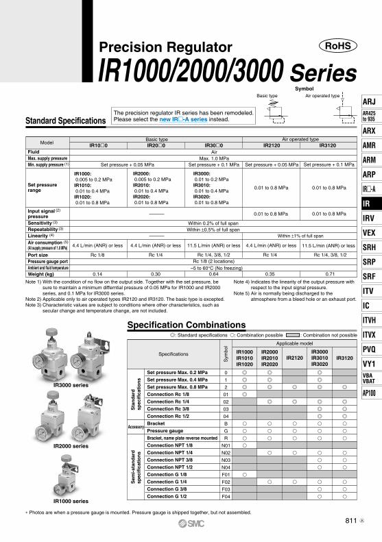
RoHS
Standard Specifications
Basic type Air operated type
Model
SensitivityRepeatabilityLinearity
Port sizePressure gauge portAmbient and fluid temperatureWeight (kg)
FiuidMax. supply pressureMin. supply pressure
Set pressure range
Input signal pressure
Air consumption(At supply pressure of 1.0 MPa)
(2)
(4)
(3)
(3)
(5)
(1)
IR100
IR1000: 0.005 to 0.2 MPaIR1010: 0.01 to 0.4 MPaIR1020: 0.01 to 0.8 MPa
Rc 1/8
0.14
IR200
IR2000: 0.005 to 0.2 MPaIR2010: 0.01 to 0.4 MPaIR2020: 0.01 to 0.8 MPa
Rc 1/4
0.30
IR300
Set pressure + 0.1 MPa
IR3000: 0.01 to 0.2 MPaIR3010: 0.01 to 0.4 MPaIR3020: 0.01 to 0.8 MPa
11.5 L/min (ANR) or less4.4 L/min (ANR) or less 4.4 L/min (ANR) or less 4.4 L/min (ANR) or less
Rc 1/4, 3/8, 1/2Rc 1/8 (2 locations)
0.64
IR2120
Set pressure + 0.05 MPa
0.01 to 0.8 MPa
Rc 1/4
0.35
0.01 to 0.8 MPa
IR3120
Set pressure + 0.1 MPa
0.01 to 0.8 MPa
11.5 L/min (ANR) or less
Rc 1/4, 3/8, 1/2
0.71
0.01 to 0.8 MPa
Basic type Air operated type
Max. 1.0 MPaAir
Set pressure + 0.05 MPa
Within 0.2% of full spanWithin ±0.5% of full span
Within ±1% of full span
–5 to 60°C (No freezing)
Symbol
Precision Regulator
IR1000/2000/3000 Series
Specification Combinations: Standard specifications : Combination possible : Combination not possible
Specifications
Sta
nd
ard
spec
ific
atio
ns
Sem
i-st
and
ard
spec
ific
atio
ns
Accessory
Set pressure Max. 0.2 MPa
Set pressure Max. 0.4 MPa
Set pressure Max. 0.8 MPa
Connection Rc 1/8
Connection Rc 1/4
Connection Rc 3/8
Connection Rc 1/2
Bracket
Pressure gauge
Bracket, name plate reverse mounted
Connection NPT 1/8
Connection NPT 1/4
Connection NPT 3/8
Connection NPT 1/2
Connection G 1/8
Connection G 1/4
Connection G 3/8
Connection G 1/2
0
1
2
01
02
03
04
B
G
R
N01
N02
N03
N04
F01
F02
F03
F04
Sym
bol Applicable model
IR1000IR1010IR1020
IR2000IR2010IR2020
IR3000IR3010IR3020
IR3120IR2120
IR3000 series
IR2000 series
IR1000 series
∗ Photos are when a pressure gauge is mounted. Pressure gauge is shipped together, but not assembled.
Note 1) With the condition of no flow on the output side. Together with the set pressure, be sure to maintain a minimum differntial pressure of 0.05 MPa for IR1000 and IR2000 series, and 0.1 MPa for IR3000 series.
Note 2) Applicable only to air operated types IR2120 and IR3120. The basic type is excepted.Note 3) Characteristic values are subject to conditions where other characteristics, such as
secular change and temperature change, are not included.
Note 4) Indicates the linearity of the output pressure with respect to the input signal pressure.
Note 5) Air is normally being discharged to the atmosphere from a bleed hole or an exhaust port.
The precision regulator IR series has been remodeled. Please select the new IR-A series instead.
811
ARJAR425to 935
ARX
AMR
ARM
ARP
IR-A
IR
IRV
VEX
SRH
SRP
SRF
ITV
IC
ITVX
ITVH
PVQ
VY1VBAVBAT
AP100
IR
A
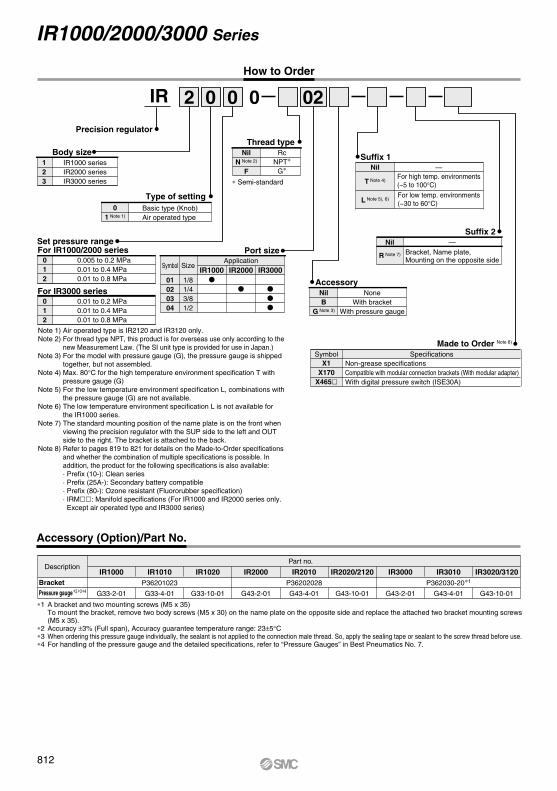
Accessory (Option)/Part No.
DescriptionIR1000
G33-2-01
IR1010P36201023
G33-4-01
IR1020
G33-10-01
IR2000
G43-2-01
IR2010P36202028
G43-4-01
IR2020/2120
G43-10-01
IR3010P362030-20∗1
G43-4-01
IR3020/3120
G43-10-01
IR3000
G43-2-01
Part no.
∗1 A bracket and two mounting screws (M5 x 35) To mount the bracket, remove two body screws (M5 x 30) on the name plate on the opposite side and replace the attached two bracket mounting screws (M5 x 35).∗2 Accuracy ±3% (Full span), Accuracy guarantee temperature range: 23±5°C�∗3 When ordering this pressure gauge individually, the sealant is not applied to the connection male thread. So, apply the sealing tape or sealant to the screw thread before use.∗4 For handling of the pressure gauge and the detailed specifications, refer to “Pressure Gauges” in Best Pneumatics No. 7.
BracketPressure gauge∗2∗3∗4
IR1000/2000/3000 Series
How to Order
IR1000 seriesIR2000 seriesIR3000 series
Basic type (Knob)Air operated type
For IR1000/2000 series
Thread type
Precision regulator
Body size
Type of setting
IR
01 Note 1)
Bracket, Name plate,Mounting on the opposite side
2
Set pressure range
0
Suffix 2
00 02
123
0.005 to 0.2 MPa0.01 to 0.4 MPa0.01 to 0.8 MPa
012
For IR3000 series0.01 to 0.2 MPa0.01 to 0.4 MPa0.01 to 0.8 MPa
012
AccessoryNilB
G Note 3)
NoneWith bracket
With pressure gauge
NilN Note 2)
F
RcNPT∗
G∗
R Note 7)
∗ Semi-standard
IR1000
IR2000
IR3000
ApplicationPort size
Symbol
01020304
Size
1/81/43/81/2
Made to Order Note 8)
X1X170
X465
Symbol SpecificationsNon-grease specificationsCompatible with modular connection brackets (With modular adapter)With digital pressure switch (ISE30A)
—Nil
Nil
T Note 4)
L Note 5), 6)
Suffix 1
For high temp. environments (−5 to 100°C)
For low temp. environments (−30 to 60°C)
—
Note 1) Air operated type is IR2120 and IR3120 only.Note 2) For thread type NPT, this product is for overseas use only according to the
new Measurement Law. (The SI unit type is provided for use in Japan.)Note 3) For the model with pressure gauge (G), the pressure gauge is shipped
together, but not assembled.Note 4) Max. 80°C for the high temperature environment specification T with
pressure gauge (G)Note 5) For the low temperature environment specification L, combinations with
the pressure gauge (G) are not available.Note 6) The low temperature environment specification L is not available for
the IR1000 series.Note 7) The standard mounting position of the name plate is on the front when
viewing the precision regulator with the SUP side to the left and OUT side to the right. The bracket is attached to the back.
Note 8) Refer to pages 819 to 821 for details on the Made-to-Order specifications and whether the combination of multiple specifications is possible. In addition, the product for the following specifications is also available:· Prefix (10-): Clean series· Prefix (25A-): Secondary battery compatible· Prefix (80-): Ozone resistant (Fluororubber specification)· IRM: Manifold specifications (For IR1000 and IR2000 series only. Except air operated type and IR3000 series)
812

Bleed
SUP (1)
Exhaust
OUT (2)OUT (2)SUP (1)
Exhaust
Bleed
Bleed
OUT (2)SUP (1)
Bleed
IN
Bleed
SUP (1) OUT (2)
Bleed
IN
Bleed
OUT (2)SUP (1)
!2
!4
@1!8
w
r
e
!2
!7
!6@1
@3
@3
@4
@2
!1
!3
!2!5
!8
@1
w
y
r
e
!2
!7
!6
@2
@4
@3
@3
@1
!1
!3
!2
!5
!8
@1
@5
@6!9
!9
!9
@6
!9
!0
o
q
!0
i
q
w
u
e
!0
!1
i
q
w
e
!9@0
@0
!1
@0@6
@5!1
@6
!0
i
!1
q
y
w
u
e
!0
o
!1
q
tValve guidetValve guide tValve guide
tValve guidetValve guide
Setting knob
Diaphragm (A)
Steel ball
Nozzle
Diaphragm (B)
Diaphragm (C)
Exhaust valve
Main valve
@6Fixed throttle
When the setting knob is turned, the nozzle is closed by the flapper allowing the supply air that flows in from the upstream side to pass through the fixed throttle. It then acts on diaphragm B as nozzle back pressure, the main valve is pushed down by the generated force, and the supply pressure flows out to the downstream side. The air pressure that flows in acts on diaphragm C. While opposing the force generated by diaphragm B it also acts on diaphragm A, opposing the compression force of the setting spring and becomes the set pressure. If the set pressure rises too high, diaphragm A is pushed up, the interval between the flapper and the nozzle widens, the nozzle back pressure drops, the balance of diaphragms B and C is broken, the main valve closes, the exhaust valve opens and the excess pressure from the downstream side is discharged to the atmosphere. In this way fine pressure variations are detected by the nozzle/flapper type pilot mechanism, and precise pressure adjustment is performed.
Working principle (For IR2000)
IR2000 IR3000
IR2120 IR3120
ConstructionIR1000
SUP side passage OUT side passage
SUP side passage OUT side passage
SUP side passage OUT side passage
SUP side passage OUT side passage
SUP side passage OUT side passage
!1
@0@0
@0
!1
Precision Regulator IR1000/2000/3000 Series
813
ARJAR425to 935
ARX
AMR
ARM
ARP
IR-A
IR
IRV
VEX
SRH
SRP
SRF
ITV
IC
ITVX
ITVH
PVQ
VY1VBAVBAT
AP100
IR
A

Construction (Refer to page 813.)
Replacement Parts
P362010-1
P362010-2
—
P36201058
—
—
—
P36201021
ø2.5 x 1.05
−
ø10 x 1.3
—
—
—
—
P36202018
1
1
—
1
—
—
—
1
3
—
1
—
—
—
—
1
1
1
1
—
1
—
—
1
2
3
1
—
—
—
—
1
1
1
—
—
—
1
1
—
—
1
1
1
2
1
3
1
1
1
1
—
1
—
—
1
2
3
1
—
—
—
—
1
1
1
—
—
—
1
1
—
—
1
1
1
2
1
3
1
P362020-2
P362020-5
P36202019
—
P36202068#1
—
—
P36202026
ø1.42 x 1.52
ø4.5 x 1
JISB2401P11
—
—
—
—
P36202018
P362020-2
P362030-34
—
—
—
P36203009#1
P36203010#1
—
—
ø4.5 x 1
ø27.8 x 1.5
JISB2401P5 Note 2)
JISB2401P16 Note 2)
P36203015
P36203016
P36203017
NBR, other
NBR, other
NBR, other
Stainless steel, NBR
Stainless steel, H-NBR
Brass, NBR
Brass, NBR
NBR, other
H-NBR
NBR
NBR
NBR
NBR
NBR
NBR
Stainless steel
Diaphragm assembly
Diaphragm assembly
Diaphragm
Valve
Valve
Valve
Valve
Damper
O-ring
O-ring
O-ring
O-ring
O-ring
Seal (A)
Seal (B)
Fixed throttle
No. Description MaterialQty.
P362020-13
P362020-5
P36202019
—
P36202068#1
—
—
P36202026
ø1.42 x 1.52
ø4.5 x 1
JISB2401P11
—
—
—
—
P36202018
P362020-13
P362030-34
—
—
—
P36203009#1
P36203010#1
—
—
ø4.5 x 1
ø27.8 x 1.5
JISB2401P5 Note 2)
JISB2401P16 Note 2)
P36203015
P36203016
P36203017Repair kit no. (A set of above nos. !1 to @6.)
Note 1) The replacement parts are shipped with the repair kit number.Note 2) Use mini-flick type.
IR100 IR200 IR300 IR2120 IR3120Part no. Part no. Part no. Part no. Part no.Qty. Qty. Qty. Qty.
11
12
13
14
15
16
17
18
19
20
21
22
23
24
25
26
KT-IR1000 KT-IR2000 KT-IR3000 KT-IR2120 KT-IR3120
Main Component Parts
—
Resin
—
—
—
—
Brass
—
Resin
Resin/Steel
—
Aluminum alloy
Aluminum alloy
Aluminum alloy
Aluminum alloy
Aluminum alloy
—
—
—
Brass
Bonnet
Nozzle valve element
Body
Intermediate body
Valve guide
Cover
Bleed ring
Setting knob
Adjusting screw
Bush
No. DescriptionMaterial
—
Brass
Aluminum alloy
Resin
—
Steel
Aluminum alloy
Aluminum alloy
Aluminum alloy
—
—
IR100 IR200 IR300 IR2120 IR31201
2
3
4
5
6
7
8
9
10
IR1000/2000/3000 Series
813-1A


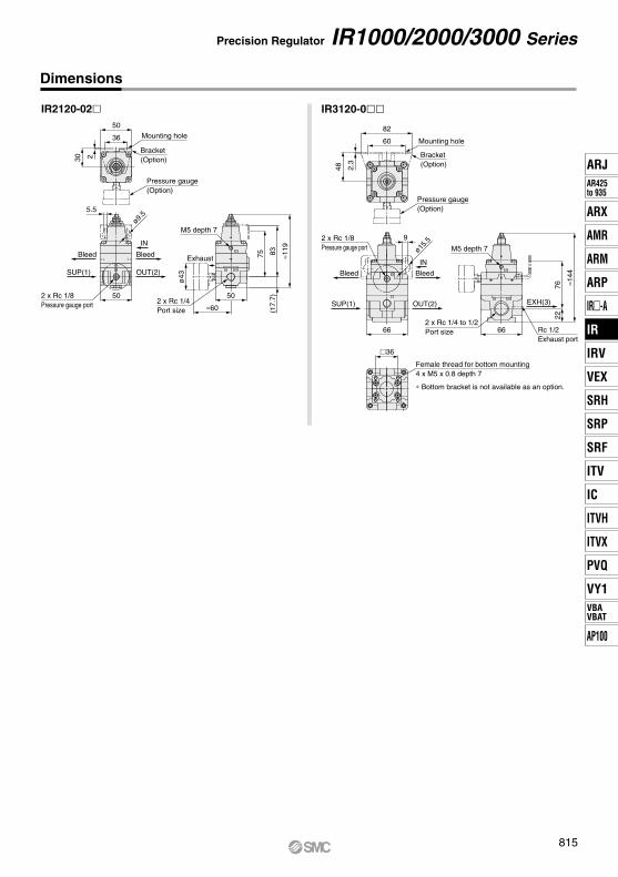
Dimensions
IR100-01 IR200-02
IR300-0
50 Mounting hole
Panel mounting hole
ø12.5
Panel
5050
Exhaust
≈60
OUT(2)SUP(1)
Bleed
M6 x P0.55.5
ø9.5
Max
.4
63
ø43
71(1
7.7)
≈124
Bracket(Option)
Pressure gauge(Option)
302 36
Panel
ø15.
5
2.3
48
Bleed
SUP(1)
66
OUT(2)
≈68
66
EXH(3)
9
ø43
76
≈148
22
M6 x P0.5
Mounting hole
Bracket(Option)
Pressure gauge(Option)
8260
2 x Rc 1/8Pressure gauge port
2 x Rc 1/4 to 1/2Port size
Rc 1/2Exhaust port
2 x Rc 1/4Port size
2 x Rc 1/8Pressure gauge port
Panel mounting hole
ø12.5
Max
.4
∗ When mounting on a panel, refer to page 822 in Specific Product Precautions.
∗ When mounting on a panel, refer to page 822 in Specific Product Precautions.
IR1000/2000/3000 Series
36
∗ Bottom bracket is not available as an option.
Female thread for bottom mounting4 x M5 x 0.8 depth 7
EXH
Panel mounting hole
Bleed
SUP(1) OUT(2)G OUT2
SMC
2842
252
Mounting hole
Bracket(Option)
Pressure gauge(Option)
ø10.5
Max
.4
ø8.5
4.5
35
2 x Rc 1/8Pressure gauge port
ø30
≈43
35
M5 x P0.5
≈92
52.5
46
2 x Rc 1/8Port size
9.5
∗ When mounting on a panel, refer to page 822 in Specific Product Precautions.
814A
IN
OUT2
G
G
IN
2 OUT
IR2120-02 IR3120-0
ø9.5
50
36
230
5.5
Mounting hole
Bracket(Option)
Pressure gauge(Option)
≈119
8375
(17.
7)
M5 depth 7
≈60
ø43
2 x Rc 1/4Port size
2 x Rc 1/8Pressure gauge port
50
Pressure gauge(Option)
82
60
48 2.3
Mounting hole
Bracket(Option)
≈144
7622
Rc 1/2Exhaust port
662 x Rc 1/4 to 1/2Port size
M5 depth 7
2 x Rc 1/8Pressure gauge port
66
9
BleedBleed
IN
SUP(1)
IN
ø15.5
EXH(3)
Exhaust
OUT(2)
OUT(2) BleedBleedSUP(1)
50
36
∗ Bottom bracket is not available as an option.
Female thread for bottom mounting4 x M5 x 0.8 depth 7
Precision Regulator IR1000/2000/3000 Series
Dimensions
815
ARJAR425to 935
ARX
AMR
ARM
ARP
IR-A
IR
IRV
VEX
SRH
SRP
SRF
ITV
IC
ITVX
ITVH
PVQ
VY1VBAVBAT
AP100
IR

0 50 100 200 250150
0.1
0.15
0.05
0.2
0 50 100 150 200 250 300 350
0.1
0.2
0.3
0.4
0 100 200 300 400 500
0.1
0.2
0.3
0.4
0.5
0.6
0.7
0.8
040 2080 60100140 120
0.1
0.2
0.3
0.4
0.5
0.2
0.3
0.4
04080120160200
0.1
0.5
0.6
0.7
0100200
0.1
0.2
0.3
0.4
0.5
0 0.20.1 0.40.3 0.60.5 0.80.7 0.9
0.196
0.198
0.200
0.202
0.204
0 0.20.1 0.3 0.4 0.60.5 0.80.7 0.9
0.196
0.198
0.200
0.202
0.204
300
0.6
0.7
0.8
0.9
1.0
0 0.20.1 0.3 0.4 0.60.5 0.80.7 0.9
0.196
0.198
0.200
0.202
0.204
1.0
1.0
1.0
Flow Rate Characteristics∗ Testing methods conform to JIS B 8372.
IR1000-01 IR1000-01 IR1000-01
Back pressure: 0.7 MPa
Back pressure: 1.0 MPa
Back pressure: 0.5 MPa
Supply pressure: 0.3 to 1.0 MPa Set pressure: 0.2 MPa
Flow rate: 0 L/min (ANR)Supply pressure: 0.5 MPa
IR1000 Series
IR1010-01 IR1010-01 IR1010-01
IR1020-01 IR1020-01 IR1020-01
Supply pressure: 0.7 MPa
Supply pressure: 1.0 MPa
Flow rate (L/min (ANR))
Set
pre
ssur
e (M
Pa)
Flow rate (L/min (ANR))
Set
pre
ssur
e (M
Pa)
Flow rate (L/min (ANR))
Set
pre
ssur
e (M
Pa)
Relief flow rate (L/min (ANR))
Set
pre
ssur
e (M
Pa)
Set
pre
ssur
e (M
Pa)
Relief flow rate (L/min (ANR))
Relief flow rate (L/min (ANR))
Set
pre
ssur
e (M
Pa)
Supply pressure P1 (MPa)
Set
pre
ssur
e P
2 (M
Pa)
Supply pressure P1 (MPa)
Supply pressure P1 (MPa)
Set
pre
ssur
e P
2 (M
Pa)
Set
pre
ssur
e P
2 (M
Pa)
Relief Characteristics Pressure Characteristics
Set point
Set point
Set point
∗ The operating conditions or external disturbance may affect each of the characteristics. So, the characteristic values shown below are not guaranteed.
IR1000/2000/3000 Series
816
0 100 200 300 400 500 600 700
0.05
0.1
0.15
0.2
0 100 200 300 400 500 600 700 800 900
0.1
0.2
0.3
0.4
0 200 400 600 800 1000 1200 1400
0.1
0.2
0.3
0.4
0.5
0.6
0.7
0.8
0 200 400 600 800 1000 1200 1400
0.1
0.2
0.3
0.4
0.5
0.6
0.7
0.8
0100200300400
0.1
0.2
0.3
0.4
0.5
0.2
0.3
0.4
0100200300400500
0.1
0.5
0.6
0.7
0200400600800
0.1
0.2
0.3
0.4
0.5
0 0.20.1 0.40.3 0.60.5 0.80.7 0.9
0.196
0.198
0.200
0.202
0.204
0 0.20.1 0.3 0.4 0.60.5 0.80.7 0.9
0.196
0.198
0.200
0.202
0.204
1000
0.6
0.7
0.8
0.9
1.0
0200400600800
0.1
0.2
0.3
0.4
0.5
1000
0.6
0.7
0.8
0.9
1.0
0 0.20.1 0.3 0.4 0.60.5 0.80.7 0.9
0.196
0.198
0.200
0.202
0.204
1.0
1.0
1.0
0 0.20.1 0.3 0.4 0.60.5 0.80.7 0.9
0.196
0.198
0.200
0.202
0.204
1.0
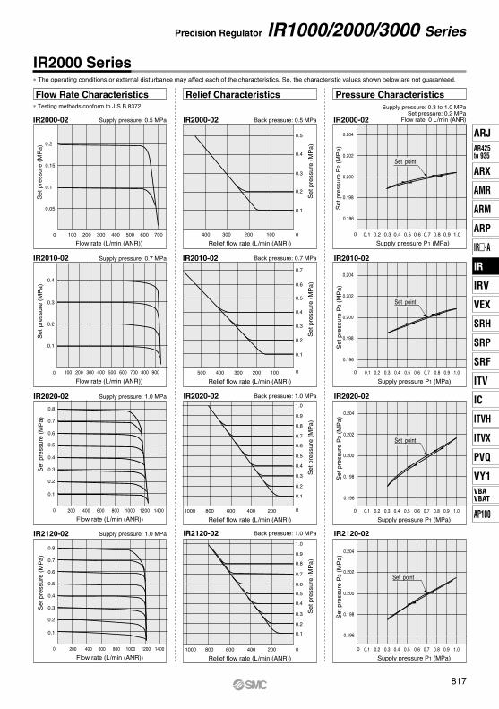
Flow Rate Characteristics∗ Testing methods conform to JIS B 8372.
IR2000-02 IR2000-02 IR2000-02
Supply pressure: 0.3 to 1.0 MPa Set pressure: 0.2 MPa
Flow rate: 0 L/min (ANR)Back pressure: 0.5 MPaSupply pressure: 0.5 MPa
IR2000 Series
IR2010-02 IR2010-02 IR2010-02
IR2020-02 IR2020-02 IR2020-02
Supply pressure: 0.7 MPa Back pressure: 0.7 MPa
Supply pressure: 1.0 MPa Back pressure: 1.0 MPa
IR2120-02 IR2120-02 IR2120-02Supply pressure: 1.0 MPa Back pressure: 1.0 MPa
Flow rate (L/min (ANR))
Set
pre
ssur
e (M
Pa)
Flow rate (L/min (ANR))
Set
pre
ssur
e (M
Pa)
Flow rate (L/min (ANR))
Set
pre
ssur
e (M
Pa)
Flow rate (L/min (ANR))
Set
pre
ssur
e (M
Pa)
Relief flow rate (L/min (ANR))
Set
pre
ssur
e (M
Pa)
Set
pre
ssur
e (M
Pa)
Relief flow rate (L/min (ANR))
Relief flow rate (L/min (ANR))
Set
pre
ssur
e (M
Pa)
Supply pressure P1 (MPa)
Set
pre
ssur
e P
2 (M
Pa)
Supply pressure P1 (MPa)
Relief flow rate (L/min (ANR))
Set
pre
ssur
e (M
Pa)
Supply pressure P1 (MPa)
Set
pre
ssur
e P
2 (M
Pa)
Set point
Set point
Supply pressure P1 (MPa)
Set
pre
ssur
e P
2 (M
Pa)
Set point
Set point
Set
pre
ssur
e P
2 (M
Pa)
Relief Characteristics Pressure Characteristics
∗ The operating conditions or external disturbance may affect each of the characteristics. So, the characteristic values shown below are not guaranteed.
Precision Regulator IR1000/2000/3000 Series
817
ARJAR425to 935
ARX
AMR
ARM
ARP
IR-A
IR
IRV
VEX
SRH
SRP
SRF
ITV
IC
ITVX
ITVH
PVQ
VY1VBAVBAT
AP100
IR
0 1000 2000 3000 4000
0.1
0.15
0.05
0.2
0 1000 2000 3000 4000 5000 6000
0.1
0.2
0.3
0.4
0 1000 2000 3000 4000 5000 6000
0.1
0.2
0.3
0.4
0.5
0.6
0.7
0.8
0500100015002000250030003500
0.1
0.2
0.3
0.4
0.5
0.2
0.3
0.4
01000200030004000
0.1
0.5
0.6
0.7
010002000300040005000
0.1
0.2
0.3
0.4
0.5
0 0.20.1 0.40.3 0.60.5 0.80.7 0.9
0.196
0.194
0.198
0.200
0.202
0.204
0 0.20.1 0.3 0.4 0.60.5 0.80.7 0.9
0.196
0.194
0.198
0.200
0.202
0.204
6000
0.6
0.7
0.8
0.9
1.0
0 0.20.1 0.3 0.4 0.60.5 0.80.7 0.9
0.196
0.194
0.198
0.200
0.202
0.204
1.0
1.0
1.0
0 1000 2000 3000 4000 5000 6000
0.1
0.2
0.3
0.4
0.5
0.6
0.7
0.8
010002000300040005000
0.1
0.2
0.3
0.4
0.5
6000
0.6
0.7
0.8
0.9
1.0
0 0.20.1 0.3 0.4 0.60.5 0.80.7 0.9
0.196
0.194
0.198
0.200
0.202
0.204
1.0
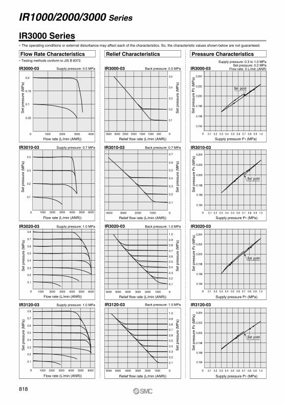
Flow Rate Characteristics∗ Testing methods conform to JIS B 8372.
IR3000-03 IR3000-03 IR3000-03Supply pressure: 0.5 MPa Back pressure: 0.5 MPa
IR3000 Series
IR3010-03 IR3010-03 IR3010-03
IR3020-03 IR3020-03 IR3020-03
Supply pressure: 0.7 MPa Back pressure: 0.7 MPa
Supply pressure: 1.0 MPa Back pressure: 1.0 MPa
IR3120-03 IR3120-03 IR3120-03Supply pressure: 1.0 MPa Back pressure: 1.0 MPa
Flow rate (L/min (ANR))
Set
pre
ssur
e (M
Pa)
Flow rate (L/min (ANR))
Set
pre
ssur
e (M
Pa)
Flow rate (L/min (ANR))
Set
pre
ssur
e (M
Pa)
Relief flow rate (L/min (ANR))
Set
pre
ssur
e (M
Pa)
Set
pre
ssur
e (M
Pa)
Relief flow rate (L/min (ANR))
Relief flow rate (L/min (ANR))
Set
pre
ssur
e (M
Pa)
Supply pressure P1 (MPa)
Set
pre
ssur
e P
2 (M
Pa)
Supply pressure P1 (MPa)
Supply pressure P1 (MPa)
Set
pre
ssur
e P
2 (M
Pa)
Flow rate (L/min (ANR))
Set
pre
ssur
e (M
Pa)
Relief flow rate (L/min (ANR))
Set
pre
ssur
e (M
Pa)
Supply pressure P1 (MPa)
Set
pre
ssur
e P
2 (M
Pa)
Set
pre
ssur
e P
2 (M
Pa)
Relief Characteristics Pressure Characteristics
Set point
Set point
Set point
Set point
Supply pressure: 0.3 to 1.0 MPa Set pressure: 0.2 MPa
Flow rate: 0 L/min (ANR)
∗ The operating conditions or external disturbance may affect each of the characteristics. So, the characteristic values shown below are not guaranteed.
IR1000/2000/3000 Series
818

IR1000/2000/3000 Series
Made to OrderPlease contact SMC for detailed dimensions, specifications, each part number and lead times.
How to Order
Precision regulator
Basic type (Knob)Air operated type
Type of setting0
1 Note 1)
IR1000 seriesIR2000 seriesIR3000 series
Body size123
Set pressure rangeFor IR1000/2000 series
0.005 to 0.2 MPa0.01 to 0.4 MPa0.01 to 0.8 MPa
012
For IR3000 series0.01 to 0.2 MPa0.01 to 0.4 MPa0.01 to 0.8 MPa
012
2IR 0 00 02
IR1000
IR2000
IR3000
ApplicationPort size
Symbol
01020304
Size
1/81/43/81/2
Note 1) Air operated type is IR2120 and IR3120 only.Note 2) For thread type NPT, this product is for overseas use only according to the new Measurement Law. (The SI unit type is provided for use in Japan.)Note 3) For the model with pressure gauge (G), the pressure gauge is shipped together, but not assembled.Note 4) When combining multiple prefixes and suffixes, please contact SMC.Note 5) With pressure gauge type: Max. 80°CNote 6) One modular adapter is shipped together, but not assembled.Note 7) Digital pressure switch is shipped together, but not assembled.
T/LX1
X170
X465
Symbol SpecificationsFor high and low temp. environmentsNon-grease specificationsCompatible with modular connection brackets (With modular adapter)With digital pressure switch(ISE30A)
Suffix (Made to Order)
Thread typeNil
N Note 2)
F
RcNPT
G
Note 5)
Prefix
10-25A-80-
SymbolClean seriesSecondary battery compatibleOzone resistant
Specifications
Made to Order Combinations Note 4)
Specifications
Clean series
Secondary battery compatible
Ozone resistant
For high temperature
For low temperature
Non-grease specifications
Compatible with modular connection brackets (With modular adapter) Note 6)
With digital pressure switch Note 7)
Manifold specifications
10-
25A-
80-
T
L
X1
X170
X465IRM
123
4
5678
SymbolApplicable model Accessory
Pressure gauge (G)IR100
IR200
IR300
IR3120IR2120
: Combination possible : Combination possible conditionally : Combination not possible
AccessoryNilB
G Note 3)
NoneWith bracket
With pressure gauge
819
ARJAR425to 935
ARX
AMR
ARM
ARP
IR-A
IR
IRV
VEX
SRH
SRP
SRF
ITV
IC
ITVX
ITVH
PVQ
VY1VBAVBAT
AP100
IR

30
≈97
≈130
rInterfacetInterface with bracket
qIR100--X170
wAF20-A
eAFM20-A
41
≈129
≈173
qIR20--X170
wAF30-A
eAFM30-A
50
≈169
≈225
qIR30--X170wAF40-A
eAFM40-A
For High/Low Temperature Environments4
TL
For high temperatureFor low temperature
For high/low temperature environments
SpecificationsSymbol
EnvironmentAmbient temperatureRubber material
T
TFor high temp. environments
−5 to 100°CFluororubber
LFor low temp. environments
−30 to 60°CSpecial NBR
IR 0
Non-grease Specifications5
Non-grease specifications
X1IR 0
Note 1) Assembly is performed in an ordinary assembly environment.Note 2) Parts are not washed.Note 3) Fluorine grease is used on the following parts:
· IR1000/2000 series: Part of the non-wetted parts (threaded part on the setting knob)
· IR3000 series: Part of the wetted parts (sliding parts) and non-wetted parts (threaded part on the setting knob)
Compatible with Modular Connection Brackets6
Compatible with modular connection brackets
X170IR 0
One modular adapter (E210/E310/E410 series) compatible with the port size of the regulator is provided. Connecting the modular adapter to the SUP port of the regulator enables the regulator to be connected to the modular connection bracket (Y200-A/Y300-A/Y400-A series).
Secondary Battery Compatible2
CleanlinessBleed hole
EXH port
Breathing port
Pressure gaugeGrease
ISO Class 3With M5 fitting (Applicable tubing O.D. ø6)
Oil-free + Stud parts nickle platedFluorine grease
IR1000/2000 series: With M5 fitting (Applicable tubing O.D. ø6)IR3000 series: Rc1/2 female thread
IR1000 series: With M3 fitting (Applicable tubing O.D. ø4)IR2000/3000 series: With M5 fitting (Applicable tubing O.D. ø6)
Ozone Resistant3Fluororubber is used for rubber seal materials.
Note 1) Electroless nickel plating is used.Note 2) Combinations with the pressure gauge are not available.Note 3) Air operated type is not available.
Clean Series1
Specifications
10
Clean series
IR 0
80
Ozone resistant
IR 0
SpecificationsParts materialParts surface treatmentGrease
25A
Secondary battery compatible
Material mainly composed of copper or zinc is not used.Zinc chromate or copper-based plating is not used.
Grease compatible with low dew point
IR 00
Modular Combination Example
qRegulatorwAir filtereMist separatorrInterfacetInterface with bracket
IR100--X170AF20-A
AFM20-AY200-A
Y200T-A
IR20--X170AF30-A
AFM30-AY300-A
Y300T-A
IR30--X170AF40-A
AFM40-AY400-A
Y400T-A
Description
<Combination example>
Applicable model
Note 1) The interface and interface with bracket listed above cannot be connected to the standard type.Please order a modular adapter (E210/310/410 series) separately when connecting the standard type with modular connections.
Note 2) The modular adapter attached to the Made-to-Order product (IR-X170) is shipped together, but not assembled. Refer to page 649 for the recommended tightening torque necessary to connect the modular adapter.
IR1000/2000/3000 Series
Note 3) Air filter, mist separator, interface and interface with bracket are not included with the Made-to-Order product (-X170). Order them separately if required.
Note 4) Product numbers with the bracket are not available for IR-X170. As the interface with the bracket is used, it is not necessary to attach the bracket to the IR.
Note 1) The low temperature environment specification L is not available for the IR1000 series.Note 2) For the low temperature environment specification L, combinations with the pressure
gauge (G) are not available.Note 3) Max. 80°C for the high temperature environment specification T with pressure gauge (G)
820

With Digital Pressure Switch7 Manifold Specifications (Except IR2120 and IR3000 series)8With digital pressure switch (model no: ISE30A-01--ML).Mount a digital pressure switch into the connection port forpressure gauge, as it is not mounted at the time of shipment.
012
0.2 MPa setting 1 to n pcs.0.4 MPa setting 1 to n pcs.0.8 MPa setting 1 to n pcs.
Set pressure and quantity
Nil
G
None
IR1000 series: G33--01IR2000 series: G43--01
Accessory (Pressure gauge)
2
8
Stations
2 to 8 station manifold type regulators.(Please contact SMC regarding 9 or more stations.)
IRM 10 3 G
Manifold type regulator
Body size
SpecificationsStations
Port
Set pressureAccessory (Pressure gauge)
2 to 8 stations
0.2 MPa, 0.4 MPa and 0.8 MPa settings can be combined.
G33--01(IR1000 series), G43--01(IR2000 series)
Common SUPIndividual OUTIndividual EXH (From IR body)
IR1000 series: 1/4, IR2000 series: 1/2IR1000 series: 1/8, IR2000 series: 1/4
…
2 stations
8 stations
…
1020
IR1000 seriesIR2000 series
Pressure Switch Specifications−0.1 to 1
0.001
12 to 24 VDC±10%, Ripple (p-p) 10% or less(With reverse connection protection)
40 mA or less0 to 50�
NilNF
Thread type (Thread on the manifold base)
RcNPT
G
Note 1) Regulators to be manifolded are counted starting from stations 1 on the left side with the OUT ports in front.
Note 2) When regulators with a different set pressure are manifolded, viewing OUT ports from front, the low pressure range is installed on the left side and high pressure range is on the right side. In case of the Example 2) above mentioned, stations 1 and 2 are of 0.2 MPa setting, stations 3 and 4 are of 0.4 MPa setting, and station 5 is of 0.8 MPa setting.
Note 3) When a blanking plate is needed, please contact SMC for the part number, etc.
Note 4) For thread type NPT, this product is for overseas use only according to the new Measurement Law. (The SI unit type is provided for use in Japan.)
Note 5) For the model with pressure gauge (G), the pressure gauge is shipped together, but not assembled.
With digital pressure switch
Switch output specifications
Set pressure range (MPa)
Power supply voltage
Current consumptionTemperature
Resolution of setting and display (MPa)
SymbolABCD
Output specificationsNPN open collector 1 outputPNP open collector 1 output
NPN open collector 1 output + Analog voltage outputNPN open collector 1 output + Analog current output
Note 1) Please contact SMC separately for details about the external dimensions, etc.
Note 2) For details on handling digital pressure switch and specifications, refer to Best Pneumatics No.8.
Note 3) Digital pressure switch is packed together.Note 4) The symbol G that indicates the inclusion of the pressure gauge is
not necessary for the part number.Note 5) Not applicable to both high and low temperature environments.
AIR X4650
Made to Order IR1000/2000/3000 Series
Example 1) 0.4 MPa setting with 6 stationsIRM10-6G-16
Example 2) 0.2 MPa setting 2 pcs.,0.4 MPa setting 2 pcs.,0.8 MPa setting 1 pc. with 5 stationsIRM20-5G-021221
821
ARJAR425to 935
ARX
AMR
ARM
ARP
IR-A
IR
IRV
VEX
SRH
SRP
SRF
ITV
IC
ITVX
ITVH
PVQ
VY1VBAVBAT
AP100
IR

Air Supply
Caution
Maintenance
Warning
Operation
Caution
Handling
Caution
Warning
Warning
Precautions for IR100 only
IR1000/2000/3000 SeriesSpecific Product Precautions 1Be sure to read this before handling the products. Refer to back page 50 for Safety Instructions and pages 387 to 391 for Precautions on every series.
1. When the precision regulator with pressure gauge is used, do not apply impact to the product by dropping it, etc. during transportation or installation.This may cause misalignment of the pressure gauge pointer.
1. Do not use a precision regulator outside the range of its specifications as this can cause failure. (Refer to specifications.)
2. When mounting is performed, make connections while confirming port indications.
3. Screw a panel nut with the recommended proper torque when mounting onto a panel. Looseness or faulty sealing will occur if tightening torque is insufficient, while thread damage will result if the torque is excessive.
4. If a directional switching valve (solenoid valve, mechanical valve, etc.) is mounted on the supply side of the precision regulator and repeatedly switched ON and OFF, wear of the nozzle/flapper section will be accelerated and a discrepancy in the setting value may occur. Therefore, avoid using a directional switching valve on the supply side. In the event a directional switching valve will be used, install it on the output side of the precision regulator.
5. The accessory pressure gauge is supplied with the preci-sion regulator in the unassembled status. Before using the precision regulator, be sure to install the pressure gauge at the gauge port of the precision regulator. At this time, the recommended tightening torque of the pressure gauge is 7 to 9 N·m.
IR1000 IR2000 IR300012.5 21 21
(N·m)Recommended Proper Torque
1. If the supply pressure line contains drain or dust, etc., the fixed throttle can become clogged leading to malfunction∗, and therefore, in addition to an air filter (SMC AF series) be sure to install a mist separator (SMC AM, AFM series) and remove drain, etc. periodically.For air quality, refer to Air Preparation Equipment Model Selection Guide on pages 2 and 3. For the maintenance method of the air preparation equipment, refer to the recommended method for the model in use.
2. Never use a lubricator on the supply side of the precision regulator, as this will positively cause the fixed throttle to become clogged and result in a malfunction∗. If lubrication is required for terminal devices, connect a lubricator on the output side of the precision regulator.∗ The following may occur if the fixed throttle is clogged or is
getting clogged. No output Set pressure drops. Set pressure is unstable. Outlet pressure slowly rises.
1. When the valve guide (refer to construction drawing on page 813) is to be removed during maintenance, first reduce the set pressure to “0” and completely shut off the supply pressure.
2. When a pressure gauge is to be mounted, remove the plug after reducing the set pressure to “0”.
1. When remounting the valve guide after removing it for maintenance, tighten the valve guide slowly using a tightening torque of no more than 0.6 N·m.Since the valve guide on this product is made of resin, there is a danger of damage if tightened with a torque exceeding the prescribed value.1. Please consult with SMC when using the product in
applications other than compressed air.2. Do not use compressed air which includes chemicals,
synthetic oils containing organic solvents, salt or corrosive gases, etc., as this can cause damage or malfunction.
3. If the drain removal from air filter and mist separator is missed, drain will be flown out to the outlet side and may result in a malfunction of the pneumatic equipment. When removing drain is difficult, use of a filter with an auto-drain is recommended.
Operating Environment
Warning1. Do not use in an atmosphere having corrosive gases,
chemicals, sea water, water, water steam, or where there is direct contact with any of these.
2. Do not operate in locations where vibration or impact occurs.
3. In locations which receive direct sunlight, provide a protective cover, etc.
4. In locations near heat sources, block off any radiated heat.5. In locations where there is contact with spatter from water,
oil or solder, etc., implement suitable protective measures.
822
Operation
Caution
CautionPrecautions for IR300, IR3120 only
Caution
Precautions for IR2120, IR3120(air operated type) only
IR1000/2000/3000 SeriesSpecific Product Precautions 2Be sure to read this before handling the products. Refer to back page 50 for Safety Instructions and pages 387 to 391 for Precautions on every series.
6. Air is normally released from the bleed hole (the hole on the side of the body’s mid-section). This is a necessary consumption of air based on the construction of the precision regulator, and is not an abnormality.
7. Make sure to tighten the lock nut after pressure adjustment.8. There may be pulsation or noise depending on the
pressure conditions, piping conditions and ambient environment. In this case, it is possible to improve the problem by changing the pressure conditions and piping conditions.If the problem is not improved, please contact your SMC sales representative.
9. After the pressure is supplied from the upstream side or the set pressure has been adjusted, the set pressure may gradually vary depending on the secular change of internal parts.If the variation in the set pressure has become large, readjust the set pressure using the setting knob.
10. The set pressure may vary if it is influenced by the variation in ambient temperature or fluid temperature. If the set pressure varies due to the influence of temperature, consider the management of ambient and fluid temperatures.
1. The supply pressure is relatively high (approx. 0.5 MPa or more), the set pressure is low (approx. 0.1 MPa or less), and when operated with the output side released to the atmosphere, there may be pulsations in the setting pressure. In this kind of situation, operate with the supply pressure reduced as much as possible, or increase the set pressure somewhat and restrict the output line (add and adjust a stop valve, etc.).
2. The capacity of the output side is large, and when used for the purpose of a relief function, the exhaust sound will be loud when being relieved. Therefore, operate with a silencer (SMC AN series) mounted on the exhaust port (EXH port). The connection is Rc 1/2.
1. Since the output types of IR2120 and IR3120 series are the same pressure as the input signal pressure, select a type of regulator (general purpose or precision type) for input signal pressure adjustment according to the application.
2. The screw on the topmost section is a zero point adjustment screw that is locked at the factory. Adjusting the adjustment screw can cause the product to malfunction. Use the product without adjusting the adjustment screw.
823
ARJAR425to 935
ARX
AMR
ARM
ARP
IR-A
IR
IRV
VEX
SRH
SRP
SRF
ITV
IC
ITVX
ITVH
PVQ
VY1VBAVBAT
AP100
IR