precision airdrop technology conference and demonstration 2007 · 1 unclassified precision airdrop...
TRANSCRIPT
TECHNICAL REPORT AD ________________ NATICK/TP-10/003
PRECISION AIRDROP TECHNOLOGY CONFERENCE
AND DEMONSTRATION 2007
by Richard Benney
Andy Meloni Andrew Cronk
and Robyn Tiaden*
*U.S. Army Yuma Proving Grounds Yuma, AZ 85365
April 2010
Technical Paper October 22-25, 2007
Approved for public release; distribution is unlimited.
U.S. Army Natick Soldier Research, Development and Engineering Center Natick, Massachusetts 01760-5019
REPORT DOCUMENTATION PAGE Form Approved OMB No. 0704-0188
Public reporting burden for this collection of information is estimated to average 1 hour per response, including the time for reviewing instructions, searching existing data sources, gathering and maintaining the data needed, and completing and reviewing this collection of information. Send comments regarding this burden estimate or any other aspect of this collection of information, including suggestions for reducing this burden to Department of Defense, Washington Headquarters Services, Directorate for Information Operations and Reports (0704-0188), 1215 Jefferson Davis Highway, Suite 1204, Arlington, VA 22202-4302. Respondents should be aware that notwithstanding any other provision of law, no person shall be subject to any penalty for failing to comply with a collection of information if it does not display a currently valid OMB control number.
PLEASE DO NOT RETURN YOUR FORM TO THE ABOVE ADDRESS. 1. REPORT DATE (DD-MM-YYYY)
30-04-2010 2. REPORT TYPE
Technical Paper3. DATES COVERED (From - To)
22-25 October 20074. TITLE AND SUBTITLE
PRECISION AIRDROP TECHNOLOGY CONFERENCE AND DEMONSTRATION 2007
5a. CONTRACT NUMBER
5b. GRANT NUMBER
5c. PROGRAM ELEMENT NUMBER
630016. AUTHOR(S)
Richard Benney, Andy Meloni, Andrew Cronk, and Robyn Tiaden* 5d. PROJECT NUMBER
D242 5e. TASK NUMBER
C5f. WORK UNIT NUMBER
7. PERFORMING ORGANIZATION NAME(S) AND ADDRESS(ES)
8. PERFORMING ORGANIZATION REPORT NUMBER
NATICK/TP-10/003
9. SPONSORING / MONITORING AGENCY NAME(S) AND ADDRESS(ES) 10. SPONSOR/MONITOR’S ACRONYM(S)
11. SPONSOR/MONITOR’S REPORT NUMBER(S)
12. DISTRIBUTION / AVAILABILITY STATEMENT
Approved for public release; distribution is unlimited. 13. SUPPLEMENTARY NOTES *U.S. Army Yuma Proving Grounds, Yuma, AZ 85365 14. ABSTRACT
This paper describes the event planning and execution, an overview of the systems demonstrated, and the results of the fourth Precision Airdrop Technology Conference and Demonstration (PATCAD) 2007 conducted on 22-25 October 2007 at U.S. Army Yuma Proving Grounds (YPG) in Yuma, AZ. It also presents the safety and technical issues (including safety fans, airdrop trajectories and system images) regarding the planning and execution of PATCAD 2007. PATCAD 2007 was primarily facilitated by U.S. Army Natick Soldier Research, Development and Engineering Center (NSRDEC) and sponsored by many other organizations in the U.S. Department of Defense (DoD), North Atlantic Treaty Organization (NATO) as well as multiple foreign nation Ministries of Defense (MoD). It brought together members of the allied nations’ governments and militaries, academia and industry to collaborate on and witness the state of the art of precision airdrop technologies. Over 500 visitors, support staff, and aircrews representing 17 countries attended. On the first day, DoD, NATO, Deputy Under Secretary of Defense / Advanced Systems and Concepts (DUSD/AS&C), YPG and the NSRDEC hosts presented on the current state of precision airdrop. During the next 3 days, system airdrops were performed as a demonstration of a wide range of Technology Readiness Levels (TRL), not a competition. A total of 148 cargo airdrops with 37 personnel jumps were conducted on 14 sorties between 5,000 and 17,500 ft Mean Sea Level (MSL). Payload weights ranged from 5 lbs to 25,200 lbs with offsets as far as 7 km from the intended target. Cargo airdrop systems demonstrated included autonomous guided parafoil systems, guided hybrid parafoil and round canopy systems, guided round canopy systems, and unguided round canopies used in conjunction with the Joint Precision Airdrop System-Mission Planner (JPADS-MP). Personnel systems included a jumper-worn guidance unit, GPS-assisted jumper navigation aids, and a static display of an airdropped manned glider. 15. SUBJECT TERMS
16. SECURITY CLASSIFICATION OF: 17. LIMITATION OF ABSTRACT
SAR
18. NUMBER OF PAGES
24
19a. NAME OF RESPONSIBLE PERSON
Andrew Cronk a. REPORT
U
b. ABSTRACT
U
c. THIS PAGE
U 19b. TELEPHONE NUMBER (include area code)
508-233-5570 Standard Form 298 (Rev. 8-98)
Prescribed by ANSI Std. Z39.18
U.S. Army Natick Soldier Research, Development and Engineering Center ATTN: RDNS-WPA Kansas Street, Natick, MA 01760-5019
CARGO DROP TESTS AIRDROP SYSTEMS PARACHUTE JUMPING SORTIES PARACHUTES PAYLOAD WEIGHTS PRECISION AIRDROPS AIRDROP METHODOLOGY AIRLIFT OPERATIONS AIR DROP OPERATIONS PRECISION DEMONSTRATIONS CARGO PARACHUTES JOINT MILITARY ACTIVITIES JPADS(JOINT PRECISION AIRDROP SYSTEM)
UNCLASSIFIED

This page intentionally left blank
UNCLASSIFIED
1 UNCLASSIFIED
Precision Airdrop Technology Conference and Demonstration 2007
Richard Benney1, Andy Meloni2, Andy Cronk3
U.S. Army Natick Soldier Research, Development and Engineering Center Natick, MA 01760
Robyn Tiaden4
U.S. Army Yuma Proving Grounds Yuma, AZ 85365
On 22-25 October 2007, the fourth Precision Airdrop Technology Conference and Demonstration (PATCAD) 2007 was conducted at U.S. Army Yuma Proving Grounds (YPG) in Yuma, AZ. PATCAD was primarily facilitated by U.S. Army Natick Soldier Research, Development and Engineering Center (NSRDEC). It was sponsored by many other organizations in the U.S. Department of Defense (DoD), North Atlantic Treaty Organization (NATO), as well as multiple foreign nation Ministries of Defense (MoD). Including visitors, support staff and aircrews, PATCAD 2007 had over 500 attendees representing 17 countries. The first day of the event was a one-day conference where DoD, NATO, Deputy Under Secretary of Defense / Advanced Systems and Concepts (DUSD/AS&C), YPG, and NSRDEC hosts presented on the current state of precision airdrop. During the following three days, demonstration airdrops were performed. The systems demonstrated represented a wide range of Technology Readiness Levels (TRL), and thus PATCAD is not considered to be a competition. Airdrops during the demonstration days were executed from two USAF C-130s, a USAF C-17, and a contracted C-130. These aircraft conducted 148 cargo airdrops with 37 personnel jumps on 14 sorties between 5,000 and 17,500 ft Mean Sea Level (MSL). Payload weights ranged from 5 lbs to 25,200 lbs with offsets as far a 7 km from the intended target. The drop zone used was LaPosa DZ with seven surveyed targets, or impact points (IP). Cargo airdrop systems demonstrated included autonomous guided parafoil systems, guided hybrid parafoil and round canopy systems, guided round canopy systems, and unguided round canopies used in conjunction with the Joint Precision Airdrop System-Mission Planner (JPADS-MP). Personnel systems included a jumper-worn guidance unit, GPS-assisted jumper navigation aids, and a static display of an airdropped manned glider. Other systems demonstrated that support precision airdrop include the JPADS-Mission Planner, a height sensor, a composite platform, and an on-aircraft wireless gate release. This fourth occurrence of PATCAD was used to bring together members of the allied nations’ governments and militaries, academia and industry to collaborate on and witness the state of the art of precision airdrop technologies. This allows for continuous communication to minimize duplicative efforts among allied nations, identify common requirements, and enhance transition and fielding of precision airdrop technologies to support the joint coalition warfighter. This paper describes the PATCAD event planning and execution, provides an overview of the systems demonstrated, and presents the results of the event. It will present the future planned demonstration of PATCAD 2009, scheduled for October 2009. The safety and technical issues regarding the planning and execution of a large demonstration such at this will be presented, including safety fans, airdrop trajectories and system images.
1 Division Leader/Aerospace Engineer, Warfighter Protection and Aerial Delivery Directorate, RDNS-WPA, Kansas St, Natick, MA 01760, AIAA Associate Fellow 2 Aerospace Engineer, Warfighter Protection and Aerial Delivery Directorate, RDNS-WPA-T, Kansas St, Natick, MA 01760 3 Operations Research Analyst, Warfighter Protection and Aerial Delivery Directorate, RDNS-WPA-D, Kansas St, Natick, MA 01760 4 Team Leader/Aerospace Engineer, Air Delivery Systems Branch, U.S. Army Yuma Proving Ground, TEDT-YPY-AVD, 301 C St, Yuma, AZ 85365, AIAA Member
2 UNCLASSIFIED
I. Background
The fourth biennial Precision Airdrop Technology Conference and Demonstration, named PATCAD 2007, was conducted on 21-26 October 2007 at Yuma Proving Grounds (YPG) in Yuma, Arizona. Previous PATCAD were executed in 2001, 20031 and 20052. A. Sponsors PATCAD 2007 was organized and executed by the U.S. Army Natick Soldier Research, Development and Engineering Center (NSRDEC) and U.S. Army Yuma Proving Grounds. Many other organizations sponsored the event. United States sponsors included: Deputy Under Secretary of Defense/Advanced Systems and Concepts (DUSD/AS&C), U.S. Air Force Air Mobility Command (USAF AMC), U.S. Army Product Manager – Force Sustainment Systems (PM-FSS), U.S. Joint Forces Command (USJFCOM), U.S. Army Product Manager – Clothing and Individual Equipment (PM-CIE), U.S. Special Operations Command (USSOCOM), and U.S. Transportation Command (USTRANSCOM). PATCAD was also sponsored by the following foreign organizations: North Atlantic Treaty Organization (NATO), Canadian Ministry of Defense (MoD), French MoD, German MoD, and the United Kingdom MoD. B. Attendees Over 500 people attended PATCAD 2007, including U.S. Government, many foreign government officials, invited vendors from industry, flight crews, and PATCAD planning, support and execution staff. Seventeen nations were represented to include: Australia, Belgium, Canada, Denmark, France, Germany, Greece, the Netherlands, New Zealand, Norway, Portugal, Slovakia, Spain, Sweden, Turkey, the United Kingdom and the United States. Many systems were demonstrated at PATCAD 2007, including cargo airdrop systems, personnel systems and airdrop support systems. In total, 28 systems were demonstrated or displayed with sponsors from the United States, the United Kingdom, France, the Netherlands, Canada, Germany and New Zealand. C. Purpose PATCAD 2007 was intended to demonstrate and display the state-of-the-art in precision airdrop and foster collaboration between allied nations. This minimizes duplicative efforts and allows nations to combine on common requirements and future program plans. PATCAD was not a competition, as systems were at many different stages of development and supported a wide range of missions.
II. Planning A. Administrative Planning for PATCAD 2007 started approximately nine months in advance of the conference. As with previous PATCAD events, October was chosen as it is historically a dry time of year, as rain would prevent airdrops from occurring. YPG also lifts its summer restrictions based on wet-bulb temperature starting 1 October, allowing airdrops to occur past noon. Having maximum range time was critical to ensuring all systems to be demonstrated would have the time to drop. Aircraft to support the planned airdrops were reserved. Two USAF C-130s and a USAF C-17 were reserved via Joint Airborne/Air Transportability Training (JA/ATT). A contracted C-130 from International Air Response (IAR) was also reserved to support. The contract aircraft was critical to the success of PATCAD, as it allowed the demonstration of many new or foreign systems that did not have approvals in place to be airdropped from USAF AMC aircraft. A list of previous PATCAD attendees and other potential interested parties was compiled and an invitation email was sent out once exact dates were established. Because much of the contact information was based on PATCAD 2005 attendees, many emails had been changed or personnel moved from their positions at the time of PATCAD 2005. Therefore, it was critical to manage the emails and update contact information on a regular basis. Hotels were contacted in order to secure blocks of rooms at a discounted price for PATCAD attendees. This was especially important, as many winter visitors and tourist start arriving in Yuma during October. Tents and bleacher seating was set up at the drop zone for attendees and for meals. Lunch was served each of the three days with airdrop demonstrations. High winds on the Monday of PATCAD blew down many of the tent structures, forcing the set-up crew to rapidly reconstruct the tents in time for the attendees on Tuesday. A website was built and maintained in order to keep all attendees updated on PATCAD plans and information as well as provide an easy method of registration. The website was updated with schedule details as they were
3 UNCLASSIFIED
determined, forms for visitors to complete and submit prior to the event and information on the systems to be demonstrated. The website was available for public viewing and therefore had to contain no proprietary information. All vendors were required to complete, sign and submit a form indicating that all videos and images of their system, as well as any information displayed in the display booths, were public releasable. Because PATCAD was attended by many vendors, national governments and the press, it was essential that all information presented at PATCAD was able to be publicly released. Vendor booth setups were also organized in order to confirm all vendors had allocated space for display during the Monday conference and the Wednesday banquet. As attendees registered, they were provided with a packet of information, including the PATCAD schedule, fliers for each system being demonstrated and local area information. Each registrant was recorded and contact information verified. This allowed PATCAD planners to confirm a contact list for distribution of the PATCAD Final Report and DVD to all attendees. Those who registered for PATCAD but were unable to attend were also sent the PATCAD Final Report and DVD. B. Technical Technical planning for the test execution of PATCAD 2007 began about three months prior to the demonstration with the initial identification of interested airdrop vendors. With a basic outline of desired airdrop specifics per system, a draft drop schedule for the demonstration was created and passed to various planning personnel, and then airdrop aircraft for the event were pursued. Pertinent drop information per airdrop system, such as altitude, weight, and support requirements, were listed on the drop schedule per specific time block. The time blocks allotted to each system were dependent upon each system’s flight characteristics, the type of airdrop aircraft being used, and any specific needs of the crowd for adequately viewing the drop. The drop schedule received regular updates until about two weeks prior to the demonstration and was the key focal tool for maintaining planning consistency amongst all necessary support groups. Frequency deconfliction is an important technical consideration when planning a large, frequency-involved demonstration event. The Department of Defense (DOD) deems the electromagnetic spectrum a critical resource to the support of military operations, and thus strives for efficient spectrum management in order to minimize the potential for interference during the employment of spectrum dependant equipment. The DOD requires that all transmitting systems operating within the United States, intended to use the government spectrum, have an active “JF12”, or foreign equivalent, frequency allocation number assigned to them. To obtain a JF12 frequency allocation, a DD1494 request form for each transmitting system must be submitted to the appropriate Military Department Frequency Management Office (MILDEP FMO). Once a DD1494 is submitted, the governing U.S. Army FMO for YPG can issue a local temporary non-interference based frequency request authorization for use on the test range. About two months prior to the PATCAD 2007 demonstration, frequency information was gathered from each participating vendor that would be utilizing a transmitting system. This frequency allocation process, which typically requires a minimum of 30 days, was then followed for all transmitting systems. For safe execution during PATCAD 2007, a thorough system safety review was conducted for each system about one month prior to the demonstration to ensure that each system’s individual hazards were evaluated and mitigated through the implementation of operating procedures. Hazards in Army systems must be identified and the risks associated with those hazards must be properly managed while conducting a test event, as required by AR 385-163. Many system-specific risks, such as unique deployment methods, unique human factor interfaces, pre-mission planning needs, pyrotechnic cutter use, etc, can be minimized prior to testing by implementing specialized training procedures or processes. The system-specific risk mitigating procedures, which lead to maximized mission successes, are developed jointly by the test range safety personnel, the product manager, and the system manufacturer. Although each specific airdrop system possesses a unique system reliability, there always exists some level of inherent risk in every system when conducting airdrop testing. Two types of typical, potential airdrop malfunctions that were taken into account in the daily planning for every system dropped during PATCAD 2007 was a ballistic malfunction and a maximum glide malfunction. These two malfunction types, described further, can be considered the two worst-case ends of the possible malfunction spectrum for an airdrop system. A ballistic malfunction is a total failure or separation of the main decelerator, where the attached payload essentially free-falls to ground impact at a high rate of velocity. If this type of failure will occur, it will happen immediately after the system exits the airdrop aircraft, prior to the stabilization of the system under its main canopy. During a ballistic malfunction, the possible severity of damage to ground equipment or to personnel, let alone the payload itself, is greatly increased. In general, as the velocity of an item in motion increases, the less it is affected by winds as it travels through the air. Due to the high descent velocity of a payload in free-fall, coupled with the horizontal velocity the payload experiences upon aircraft exit, the ballistic path of the malfunctioned payload can be
4 UNCLASSIFIED
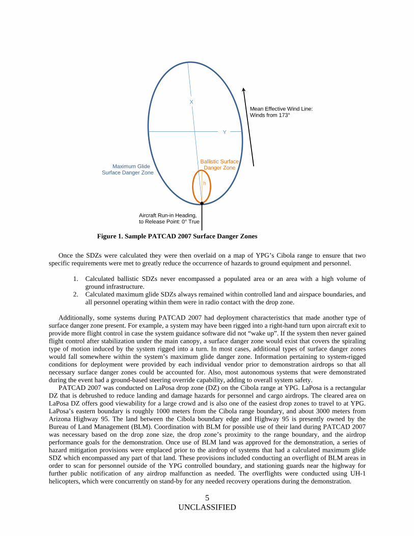
estimated with greater confidence while knowing that horizontal winds will play a limited role in that path. Of all possible airdrop malfunctions after aircraft exit, the ballistic malfunction will produce the most predictable path for impact, but also the most potentially catastrophic. The maximum glide for an airdrop system is defined as the largest amount of distance in one direction that a system with a full-open canopy can travel, as affected by winds. For standard cargo airdrop operations, where systems may have a glide ratio of less than 1:1, the maximum glide distance is often equal to the standard distance one would expect a normally functioning system, with a full-open canopy, to travel. For autonomously guided systems however, which typically have a glide ratio greater than 1:1, the maximum glide distance is the farthest distance the system can travel in one direction without use of its guidance, navigation, or controls systems, essentially only affected by winds. And some airdrop systems may have a greater probability of increasing the possible maximum glide distance due to the lack of robustness of its confluence point, i.e. where the main parachute attaches to the payload. If a system incorporates an unproven confluence point, say with new hardware to allow the payload to swivel, or perhaps when linking telemetry instrumentation in the loop, it may increase the probability of separating at that point after aircraft exit due to canopy opening forces. Although the payload in that case would ballistically free-fall to the ground after separation, the canopy could potentially re-inflate if a small, light-weight piece of hardware or telemetry remained attached, depending on how the confluence point was rigged. If the overall weight characteristics of a payload under an inflated canopy were suddenly altered as such, a new possible maximum glide distance would be present for the slowly drifting canopy. Because maximum glide flights travel on a more predictable, wind-based path, the aircraft release point can be better controlled to account for this and the possible severity of damage to ground equipment or personnel is slightly decreased. Although the potential damage severity may be decreased for such systems, to maintain better control of the maximum glide distance, especially for systems with high glide ratios, the drop altitude may need to be lowered. Every cargo system dropped during PATCAD 2007 took into account the potential for both a ballistic type of malfunction and a maximum glide type of malfunction. Equations for calculating both of these types of malfunctions can be found in Reference 1. During PATCAD 2007, the ballistic and maximum glide malfunction calculations per system were managed by depicting and controlling surface danger zones (SDZs). A surface danger zone is defined as a three-dimensional area within which an airdrop system has a possibility of traveling after aircraft exit, and is calculated by incorporating known potential failure modes. These zones can be further categorized as a ballistic danger zone or a maximum glide danger zone, as directly relates to the possible traveling area per type of malfunction. During PATCAD 2007, the ballistic and maximum glide SDZs for all cargo systems were calculated prior to the airdrop using current wind information. Weather balloons were released from the drop zone at least every two hours to provide this updated wind data for continual SDZ recalculation. Sample ballistic and maximum glide SDZs for a system with a 3:1 glide ratio that was dropped during PATCAD 2007 are shown in Figure 1, where X, Y, and h relate to distance calculations as depicted by Reference 1.
5 UNCLASSIFIED
Once the SDZs were calculated they were then overlaid on a map of YPG’s Cibola range to ensure that two specific requirements were met to greatly reduce the occurrence of hazards to ground equipment and personnel.
1. Calculated ballistic SDZs never encompassed a populated area or an area with a high volume of ground infrastructure.
2. Calculated maximum glide SDZs always remained within controlled land and airspace boundaries, and all personnel operating within them were in radio contact with the drop zone.
Additionally, some systems during PATCAD 2007 had deployment characteristics that made another type of surface danger zone present. For example, a system may have been rigged into a right-hand turn upon aircraft exit to provide more flight control in case the system guidance software did not “wake up”. If the system then never gained flight control after stabilization under the main canopy, a surface danger zone would exist that covers the spiraling type of motion induced by the system rigged into a turn. In most cases, additional types of surface danger zones would fall somewhere within the system’s maximum glide danger zone. Information pertaining to system-rigged conditions for deployment were provided by each individual vendor prior to demonstration airdrops so that all necessary surface danger zones could be accounted for. Also, most autonomous systems that were demonstrated during the event had a ground-based steering override capability, adding to overall system safety. PATCAD 2007 was conducted on LaPosa drop zone (DZ) on the Cibola range at YPG. LaPosa is a rectangular DZ that is debrushed to reduce landing and damage hazards for personnel and cargo airdrops. The cleared area on LaPosa DZ offers good viewability for a large crowd and is also one of the easiest drop zones to travel to at YPG. LaPosa’s eastern boundary is roughly 1000 meters from the Cibola range boundary, and about 3000 meters from Arizona Highway 95. The land between the Cibola boundary edge and Highway 95 is presently owned by the Bureau of Land Management (BLM). Coordination with BLM for possible use of their land during PATCAD 2007 was necessary based on the drop zone size, the drop zone’s proximity to the range boundary, and the airdrop performance goals for the demonstration. Once use of BLM land was approved for the demonstration, a series of hazard mitigation provisions were emplaced prior to the airdrop of systems that had a calculated maximum glide SDZ which encompassed any part of that land. These provisions included conducting an overflight of BLM areas in order to scan for personnel outside of the YPG controlled boundary, and stationing guards near the highway for further public notification of any airdrop malfunction as needed. The overflights were conducted using UH-1 helicopters, which were concurrently on stand-by for any needed recovery operations during the demonstration.
Ballistic Surface Danger Zone
Mean Effective Wind Line: Winds from 173°
Aircraft Run-in Heading, to Release Point: 0° True
Maximum Glide Surface Danger Zone
X
Y
h
Figure 1. Sample PATCAD 2007 Surface Danger Zones
6 UNCLASSIFIED
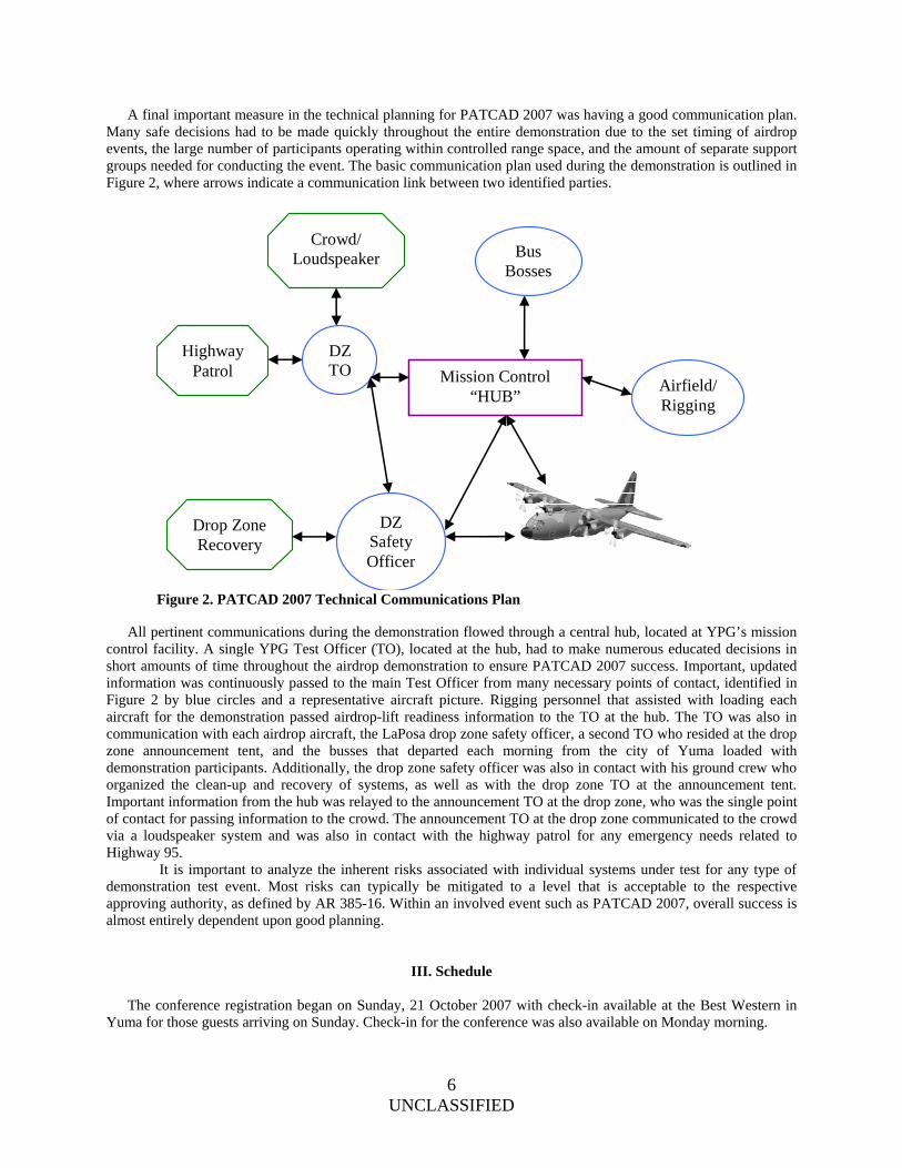
A final important measure in the technical planning for PATCAD 2007 was having a good communication plan. Many safe decisions had to be made quickly throughout the entire demonstration due to the set timing of airdrop events, the large number of participants operating within controlled range space, and the amount of separate support groups needed for conducting the event. The basic communication plan used during the demonstration is outlined in Figure 2, where arrows indicate a communication link between two identified parties.
All pertinent communications during the demonstration flowed through a central hub, located at YPG’s mission control facility. A single YPG Test Officer (TO), located at the hub, had to make numerous educated decisions in short amounts of time throughout the airdrop demonstration to ensure PATCAD 2007 success. Important, updated information was continuously passed to the main Test Officer from many necessary points of contact, identified in Figure 2 by blue circles and a representative aircraft picture. Rigging personnel that assisted with loading each aircraft for the demonstration passed airdrop-lift readiness information to the TO at the hub. The TO was also in communication with each airdrop aircraft, the LaPosa drop zone safety officer, a second TO who resided at the drop zone announcement tent, and the busses that departed each morning from the city of Yuma loaded with demonstration participants. Additionally, the drop zone safety officer was also in contact with his ground crew who organized the clean-up and recovery of systems, as well as with the drop zone TO at the announcement tent. Important information from the hub was relayed to the announcement TO at the drop zone, who was the single point of contact for passing information to the crowd. The announcement TO at the drop zone communicated to the crowd via a loudspeaker system and was also in contact with the highway patrol for any emergency needs related to Highway 95. It is important to analyze the inherent risks associated with individual systems under test for any type of demonstration test event. Most risks can typically be mitigated to a level that is acceptable to the respective approving authority, as defined by AR 385-16. Within an involved event such as PATCAD 2007, overall success is almost entirely dependent upon good planning.
III. Schedule
The conference registration began on Sunday, 21 October 2007 with check-in available at the Best Western in Yuma for those guests arriving on Sunday. Check-in for the conference was also available on Monday morning.
Mission Control “HUB”
Bus Bosses
Airfield/ Rigging
DZ Safety Officer
Drop Zone Recovery
Crowd/ Loudspeaker
DZ TO
Highway Patrol
Figure 2. PATCAD 2007 Technical Communications Plan

7 UNCLASSIFIED
Monday, 22 October was a one-day conference at the Yuma Civic and Convention Center with government briefings to the attendees. Vendors who were displaying and demonstrating systems had booths set up in the Convention Center. After the government briefings, time was dedicated for attendees to walk around, view the booths and talk with the vendors. Tuesday, 23 October consisted of a full day of airdrop demonstrations. Buses picked up attendees at the hotels in Yuma and transported them to the drop zone viewing area. Tuesday included five lifts, including two IAR C-130 lifts, three USAF C-130 lifts. At the end of the airdrops, attendees boarded the buses and were transported back to their hotels. Wednesday, 24 October consisted of a half day of airdrops with a banquet in the evening. One lift per aircraft was conducted and no personnel jumps were conducted in order to save time, allowing attendees to have time after the airdrops to prepare for the banquet. The buses were divided up, taking most of the attendees back to the hotels, while taking those who wanted a tour of YPG’s Aerial Delivery to the facility where the payloads are rigged up, systems are prepared and aircraft are loaded. The evening banquet included a briefing from the Director, JCTD on “Technical Insertion Opportunities through Rapid Prototyping.” Vendor booths were reopened during the banquet for all attendees. Thursday, 25 October was another full day of airdrops. This was also designated the VIP and Press day. As with Tuesday, six lifts were conducting, utilizing an IAR C-130, two USAF C-130s, and a USAF C-17. At the end of the airdrops, attendees were able to take the buses back to the hotels and PATCAD was considered to be officially concluded.
IV. Systems and Results Many precision airdrop systems and related support systems were demonstrated at PATCAD 07. These were deployed from or used upon four aircraft: two USAF C-130s, a contract IAR C-130, and a USAF C-17. The systems are described in the configuration in which they were demonstration at PATCAD 07. Many of these systems have had further development since PATCAD 2007. A. Cargo Airdrop Systems The following systems were demonstrated at PATCAD and are intended to deliver cargo supplies for a variety of missions. Systems are listed alphabetically by system name. Order is not intended to imply any sort of system ranking. 1. Affordable Guided Airdrop System (AGAS) – Capewell Components Co., LLC The AGAS system is capable of dropping up to 2,200 lbs using a standard A-22 CDS bundle. It uses a standard Army inventory G-12 parachute connected to an Airborne Guidance Unit (AGU) that rests on top of the Container Delivery System (CDS) bundle. The AGU uses the G-12 risers to pull slips in order to steer the system to its intended impact point. Prior to deployment from the aircraft, the AGAS receives a wind profile from the Joint Precision Airdrop Mission Planner (JPADS-MP). This allows the system to determine where to steer in order to maximize the probability of accurately navigating to the target. Twelve AGAS were dropped from 17,500 ft Mean Sea Level (MSL), comprising of one stick of four AGAS from a USAF C-130 and one stick of eight AGAS from the C-17. The C-130 releasing the AGAS was unable to receive drop sonde data, and therefore was forced to use 16 hour old forecast wind data to compute a wind profile. One of the four systems suffered a malfunction due to a low flight control battery. During the airdrop of the stick of eight AGAS, the C-17 was instructed by YPG range control to fly one minute beyond the LAR before releasing the AGAS. Three out of the twelve systems landed within 250 meters of their targets. The other systems were all outside of 500 meters. 2. Controlled Aerial Delivery System (CADS) – Cobham PLC The Controlled Aerial Delivery System is a United Kingdom sponsored system that uses a parafoil and an airborne guidance unit, under which a payload between 150 and 500 lbs (total rigged weight) is suspended. The
Figure 3. AGAS prior to aircraft loading
8 UNCLASSIFIED
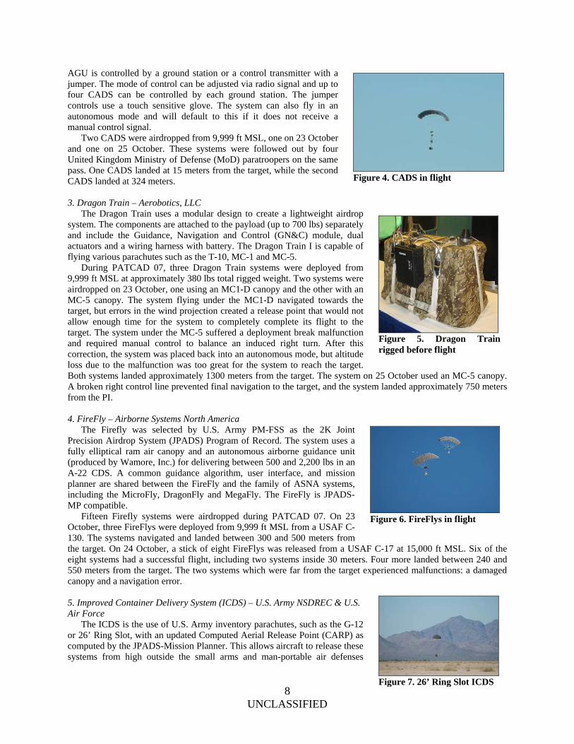
AGU is controlled by a ground station or a control transmitter with a jumper. The mode of control can be adjusted via radio signal and up to four CADS can be controlled by each ground station. The jumper controls use a touch sensitive glove. The system can also fly in an autonomous mode and will default to this if it does not receive a manual control signal. Two CADS were airdropped from 9,999 ft MSL, one on 23 October and one on 25 October. These systems were followed out by four United Kingdom Ministry of Defense (MoD) paratroopers on the same pass. One CADS landed at 15 meters from the target, while the second CADS landed at 324 meters. 3. Dragon Train – Aerobotics, LLC The Dragon Train uses a modular design to create a lightweight airdrop system. The components are attached to the payload (up to 700 lbs) separately and include the Guidance, Navigation and Control (GN&C) module, dual actuators and a wiring harness with battery. The Dragon Train I is capable of flying various parachutes such as the T-10, MC-1 and MC-5. During PATCAD 07, three Dragon Train systems were deployed from 9,999 ft MSL at approximately 380 lbs total rigged weight. Two systems were airdropped on 23 October, one using an MC1-D canopy and the other with an MC-5 canopy. The system flying under the MC1-D navigated towards the target, but errors in the wind projection created a release point that would not allow enough time for the system to completely complete its flight to the target. The system under the MC-5 suffered a deployment break malfunction and required manual control to balance an induced right turn. After this correction, the system was placed back into an autonomous mode, but altitude loss due to the malfunction was too great for the system to reach the target. Both systems landed approximately 1300 meters from the target. The system on 25 October used an MC-5 canopy. A broken right control line prevented final navigation to the target, and the system landed approximately 750 meters from the PI. 4. FireFly – Airborne Systems North America The Firefly was selected by U.S. Army PM-FSS as the 2K Joint Precision Airdrop System (JPADS) Program of Record. The system uses a fully elliptical ram air canopy and an autonomous airborne guidance unit (produced by Wamore, Inc.) for delivering between 500 and 2,200 lbs in an A-22 CDS. A common guidance algorithm, user interface, and mission planner are shared between the FireFly and the family of ASNA systems, including the MicroFly, DragonFly and MegaFly. The FireFly is JPADS-MP compatible. Fifteen Firefly systems were airdropped during PATCAD 07. On 23 October, three FireFlys were deployed from 9,999 ft MSL from a USAF C-130. The systems navigated and landed between 300 and 500 meters from the target. On 24 October, a stick of eight FireFlys was released from a USAF C-17 at 15,000 ft MSL. Six of the eight systems had a successful flight, including two systems inside 30 meters. Four more landed between 240 and 550 meters from the target. The two systems which were far from the target experienced malfunctions: a damaged canopy and a navigation error. 5. Improved Container Delivery System (ICDS) – U.S. Army NSDREC & U.S. Air Force The ICDS is the use of U.S. Army inventory parachutes, such as the G-12 or 26’ Ring Slot, with an updated Computed Aerial Release Point (CARP) as computed by the JPADS-Mission Planner. This allows aircraft to release these systems from high outside the small arms and man-portable air defenses
Figure 4. CADS in flight
Figure 5. Dragon Train rigged before flight
Figure 6. FireFlys in flight
Figure 7. 26’ Ring Slot ICDS

9 UNCLASSIFIED
(MANPAD) Weapon Engagement Zone (WEZ) while increasing accuracy over manually computed CARPs. One 26’ Ring Slot with an 1800 lbs bundle was deployed from a C-130 at 17,500 ft. The JPADS-MP was used to calculate the release point using drop sonde data. The system landed 121 meters from the target. 6. Low Cost Aerial Delivery System (LCADS) – U.S. Army PM-FSS LCADS is a family of airdrop equipment that includes a high velocity parachute, a low velocity parachute, and a Low Cost Container (LCC). These are designed to have similar performance to a 26’ Ring Slot, a G-12, and an A-22 container, respectively, with a 55 to 80% cost reduction over these current systems. The low cost of the material and ease of manufacturing help realize these cost savings. The LCADS systems are integrated into the JPADS-Mission Planner and therefore can be used in an ICDS airdrop. Two LCADS High Velocity systems were released from a USAF C-130 at 9,999 ft MSL on 23 October. The system was recovered before data could be collected, so accuracy information is not available, but video showed a successful deployment and flight. 7. MegaFly – Airborne Systems North America The MegaFly is the largest in the family of Airborne Systems North America (ASNA) guided airdrop systems, capable of carrying 30,000 lbs of cargo. The 9,000 square foot canopy is a modular design that separates into five sections for easier recovery4. The AGU uses Global Positioning System (GPS) for guidance and is produced by Wamore, Inc. Along with the MicroFly, FireFly and Dragonfly, the MegaFly uses a common guidance algorithm by Airborne Systems, user interface and mission planner. The MegaFly AGU can also fly using Draper Laboratory flight software5. Three airdrops of the MegaFly were conducted during PATCAD, all considered technical tests for an Army Technology Objective (ATO) program. Each system had a total rigged weight of 25,200 lbs and was deployed from a C-130 aircraft. All three systems used a new rigging method called a “split confluence” to reduce yaw oscillations. The tests were successful at demonstrating improved yaw stability. On 23 October, a MegaFly with Airborne Systems flight software was dropped from 12,000 ft MSL and landed 829 meters from the target. A motor malfunction occurred during the flare in the final approach. The remaining two flights used Draper Laboratory flight software. Please reference the Draper Laboratory Flight Software subsection in the “Airdrop Support Systems” section of this paper for results of those flights. 8. MicroFly – Airborne Systems North America The MicroFly is the smallest of the ASNA family of guided airdrop systems demonstrated at PATCAD 2007, capable of carrying 100 to 700 lbs of cargo. The system consists of a ram-air canopy and an AGU made by Wamore, Inc. A common algorithm by Airborne Systems, user interface and mission planner is shared by the MicroFly along with the FireFly, DragonFly, and MegaFly. The MicroFly can use multiple Airborne Systems canopies, including the MC-5, HG-380 and Intruder. Six MicroFlys were airdropped in two sticks of three. Each stick was followed by jumpers from U.S. Army PM-CIE, with the first stick deploying from 12,000 ft MSL and the second from 9,999 ft MSL. On 23 October, an inadvertent release from the aircraft deployed the systems well beyond the MicroFly Launch Acceptability Region (LAR). The systems attempted to navigate back to the target, but were released too far away to reach the drop zone. On 25 October, two systems used an MC-5 canopy and Airborne Systems flight software while the third system used an Intruder canopy and Draper Laboratory flight software. The two systems using Airborne Systems flight software landed at 97 and 180 meters from the target. The Draper Lab software flight will be described in the Draper Laboratory Flight Software section of this paper.
Figure 8. Hi-V LCADS
Figure 9. MegaFly in flight
Figure 10. MicroFly rigged on a C-130
10 UNCLASSIFIED
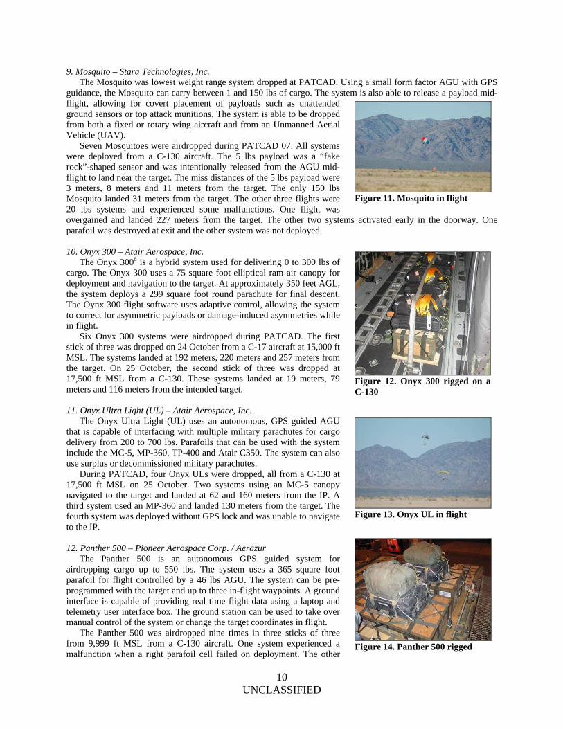
9. Mosquito – Stara Technologies, Inc. The Mosquito was lowest weight range system dropped at PATCAD. Using a small form factor AGU with GPS guidance, the Mosquito can carry between 1 and 150 lbs of cargo. The system is also able to release a payload mid-flight, allowing for covert placement of payloads such as unattended ground sensors or top attack munitions. The system is able to be dropped from both a fixed or rotary wing aircraft and from an Unmanned Aerial Vehicle (UAV). Seven Mosquitoes were airdropped during PATCAD 07. All systems were deployed from a C-130 aircraft. The 5 lbs payload was a “fake rock”-shaped sensor and was intentionally released from the AGU mid-flight to land near the target. The miss distances of the 5 lbs payload were 3 meters, 8 meters and 11 meters from the target. The only 150 lbs Mosquito landed 31 meters from the target. The other three flights were 20 lbs systems and experienced some malfunctions. One flight was overgained and landed 227 meters from the target. The other two systems activated early in the doorway. One parafoil was destroyed at exit and the other system was not deployed. 10. Onyx 300 – Atair Aerospace, Inc. The Onyx 3006 is a hybrid system used for delivering 0 to 300 lbs of cargo. The Onyx 300 uses a 75 square foot elliptical ram air canopy for deployment and navigation to the target. At approximately 350 feet AGL, the system deploys a 299 square foot round parachute for final descent. The Oynx 300 flight software uses adaptive control, allowing the system to correct for asymmetric payloads or damage-induced asymmetries while in flight. Six Onyx 300 systems were airdropped during PATCAD. The first stick of three was dropped on 24 October from a C-17 aircraft at 15,000 ft MSL. The systems landed at 192 meters, 220 meters and 257 meters from the target. On 25 October, the second stick of three was dropped at 17,500 ft MSL from a C-130. These systems landed at 19 meters, 79 meters and 116 meters from the intended target. 11. Onyx Ultra Light (UL) – Atair Aerospace, Inc. The Onyx Ultra Light (UL) uses an autonomous, GPS guided AGU that is capable of interfacing with multiple military parachutes for cargo delivery from 200 to 700 lbs. Parafoils that can be used with the system include the MC-5, MP-360, TP-400 and Atair C350. The system can also use surplus or decommissioned military parachutes. During PATCAD, four Onyx ULs were dropped, all from a C-130 at 17,500 ft MSL on 25 October. Two systems using an MC-5 canopy navigated to the target and landed at 62 and 160 meters from the IP. A third system used an MP-360 and landed 130 meters from the target. The fourth system was deployed without GPS lock and was unable to navigate to the IP. 12. Panther 500 – Pioneer Aerospace Corp. / Aerazur The Panther 500 is an autonomous GPS guided system for airdropping cargo up to 550 lbs. The system uses a 365 square foot parafoil for flight controlled by a 46 lbs AGU. The system can be pre-programmed with the target and up to three in-flight waypoints. A ground interface is capable of providing real time flight data using a laptop and telemetry user interface box. The ground station can be used to take over manual control of the system or change the target coordinates in flight. The Panther 500 was airdropped nine times in three sticks of three from 9,999 ft MSL from a C-130 aircraft. One system experienced a malfunction when a right parafoil cell failed on deployment. The other
Figure 11. Mosquito in flight
Figure 12. Onyx 300 rigged on a C-130
Figure 13. Onyx UL in flight
Figure 14. Panther 500 rigged

11 UNCLASSIFIED
eight systems successfully navigated to the target. The closest system landed 35 meters from the target with another two at 101 meters and 191 meters. The rest of the systems landed between 200 and 350 meters from the target. 13. Panther 2K – Pioneer Aerospace Corp. / Aerazur The Panther 2K is an autonomous GPS guided system capable of delivering a standard CDS bundle. The 94 lbs AGU flies under a 1,100 square foot parafoil. The Panther 2K can use the same ground station as the Panther 500 for updating of target coordinates or manual control take-over. One Panther 2K was dropped from a C-130 at 5,000 ft MSL. The system did not navigate to the intended target. 14. 10K Screamer – Strong Enterprises The 10K Screamer7 can deliver between 5,000 and 10,000 lbs of cargo and was developed under an Advanced Concept Technology Demonstration (ACTD)8. It is an autonomous, high-speed, two-stage system using an 850 square foot ram-air drogue (RAD) for deployment and navigation. At approximately 1,100 feet AGL, the system deploys a 17 foot drogue which transitions the decelerator system to two standard Army G-11 parachutes for a vertical final descent and soft touchdown. The RAD is controlled by an AGU that is identical to the 2K Screamer AGU. The 10K Screamer is fully JPADS-MP compatible and capable of targeting multiple PIs with multiple systems on a single pass. Nine 10K Screamers were dropped during PATCAD 07. On 24 October, a C-130 airdropped three 10K Screamers from 15,000 ft MSL in a single pass. Two of the systems successfully navigated to the target and landed at 265 meters and 297 meters from the target. The third system did not have GPS lock at exit. By the time the system reacquired GPS lock, it did not have enough altitude to make it back to the target. Also on 24 October, two systems were sequentially deployed from a C-17 and successfully navigated to the target, landing at 359 and 381 meters from the IP. On 25 October, four systems were airdropped on a single pass from a C-17 at 17,500 ft MSL. All four systems navigated to the target. One system, which landed 385 meters from the target, did not deploy the G-11 recovery canopies and went in under the RAD. The other three systems successfully landed at 114 meters, 127 meters, and 208 meters from the target. 15. 2K Screamer – Strong Enterprises The 2K Screamer is the 2,000 lbs version of the Screamer, using a 220 square foot RAD and a Strong Pocket G-12 for recovery. The PG-12 has the same descent characteristics as a standard Army G-12, but is half the weight and one-third the volume. The AGU, which controls the 220 sq ft RAD, is the same AGU as the 10K Screamer. The 2K Screamer is also fully compatible with the JPADS-MP. As of PATCAD, the 2K Screamer has been used in support of Operation Enduring Freedom in Afghanistan since 31 August 2006. Twelve 2K Screamers were airdropped at PATCAD 07. On 23 October, a C-130 at 17,500 ft MSL deployed four 2K Screamers. Two systems were inadvertently programmed to incorrect target coordinates by a USAF officer training a crew on the JPADS-MP prior to the flight. Because the systems were not intended to receive an in-flight update, the incorrect target was used. The miss distance from the programmed target of these two systems was 254 and 447 meters. Another system in that stick suffered broken suspension lines causing a spin. The PG-12 was manually deployed via a ground station command to prevent system destruction. On 25 October, a C-17 deployed a stick of eight 2K Screamers. All eight successfully navigated to the dropzone, with all eight systems landing between 65 and 200 meters from the target.
Figure 15. Panther 2K in flight
Figure 16. 10K Screamers after recovery canopies open
Figure 17. 2K Screamers in recovery and under the PG-12
12 UNCLASSIFIED
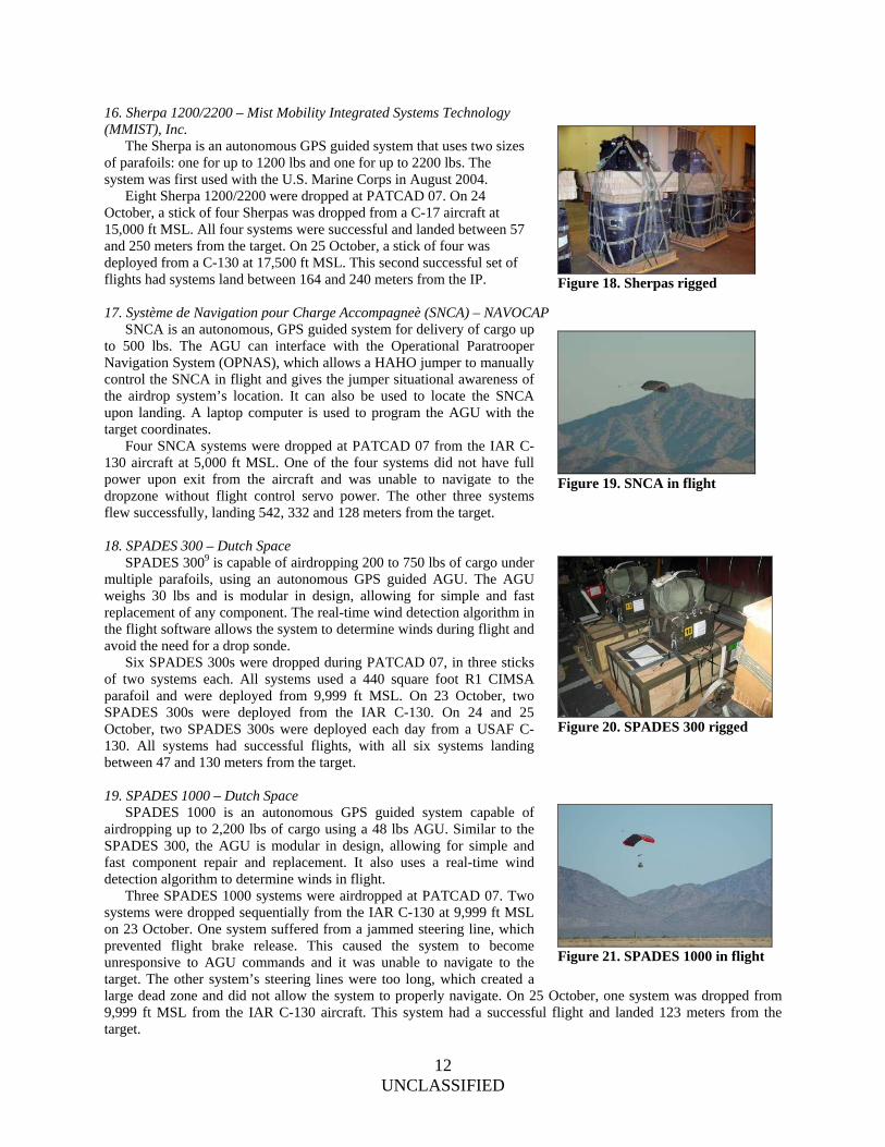
16. Sherpa 1200/2200 – Mist Mobility Integrated Systems Technology (MMIST), Inc. The Sherpa is an autonomous GPS guided system that uses two sizes of parafoils: one for up to 1200 lbs and one for up to 2200 lbs. The system was first used with the U.S. Marine Corps in August 2004. Eight Sherpa 1200/2200 were dropped at PATCAD 07. On 24 October, a stick of four Sherpas was dropped from a C-17 aircraft at 15,000 ft MSL. All four systems were successful and landed between 57 and 250 meters from the target. On 25 October, a stick of four was deployed from a C-130 at 17,500 ft MSL. This second successful set of flights had systems land between 164 and 240 meters from the IP. 17. Système de Navigation pour Charge Accompagneè (SNCA) – NAVOCAP SNCA is an autonomous, GPS guided system for delivery of cargo up to 500 lbs. The AGU can interface with the Operational Paratrooper Navigation System (OPNAS), which allows a HAHO jumper to manually control the SNCA in flight and gives the jumper situational awareness of the airdrop system’s location. It can also be used to locate the SNCA upon landing. A laptop computer is used to program the AGU with the target coordinates. Four SNCA systems were dropped at PATCAD 07 from the IAR C-130 aircraft at 5,000 ft MSL. One of the four systems did not have full power upon exit from the aircraft and was unable to navigate to the dropzone without flight control servo power. The other three systems flew successfully, landing 542, 332 and 128 meters from the target. 18. SPADES 300 – Dutch Space SPADES 3009 is capable of airdropping 200 to 750 lbs of cargo under multiple parafoils, using an autonomous GPS guided AGU. The AGU weighs 30 lbs and is modular in design, allowing for simple and fast replacement of any component. The real-time wind detection algorithm in the flight software allows the system to determine winds during flight and avoid the need for a drop sonde. Six SPADES 300s were dropped during PATCAD 07, in three sticks of two systems each. All systems used a 440 square foot R1 CIMSA parafoil and were deployed from 9,999 ft MSL. On 23 October, two SPADES 300s were deployed from the IAR C-130. On 24 and 25 October, two SPADES 300s were deployed each day from a USAF C-130. All systems had successful flights, with all six systems landing between 47 and 130 meters from the target. 19. SPADES 1000 – Dutch Space SPADES 1000 is an autonomous GPS guided system capable of airdropping up to 2,200 lbs of cargo using a 48 lbs AGU. Similar to the SPADES 300, the AGU is modular in design, allowing for simple and fast component repair and replacement. It also uses a real-time wind detection algorithm to determine winds in flight. Three SPADES 1000 systems were airdropped at PATCAD 07. Two systems were dropped sequentially from the IAR C-130 at 9,999 ft MSL on 23 October. One system suffered from a jammed steering line, which prevented flight brake release. This caused the system to become unresponsive to AGU commands and it was unable to navigate to the target. The other system’s steering lines were too long, which created a large dead zone and did not allow the system to properly navigate. On 25 October, one system was dropped from 9,999 ft MSL from the IAR C-130 aircraft. This system had a successful flight and landed 123 meters from the target.
Figure 18. Sherpas rigged
Figure 19. SNCA in flight
Figure 20. SPADES 300 rigged
Figure 21. SPADES 1000 in flight
13 UNCLASSIFIED
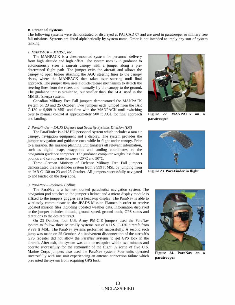
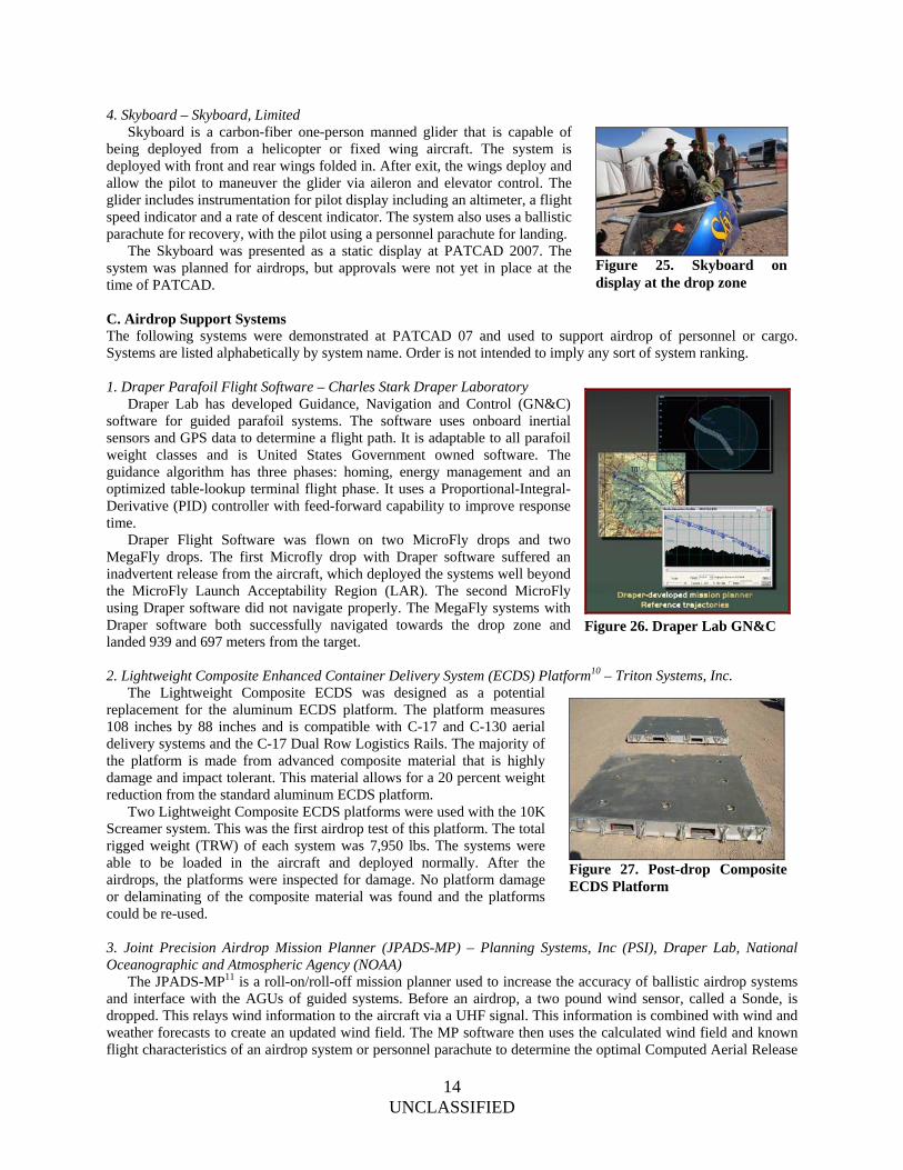
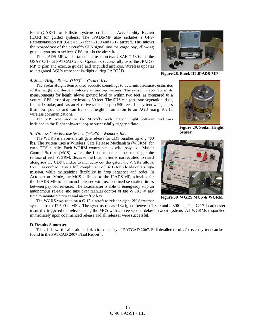
B. Personnel Systems The following systems were demonstrated or displayed at PATCAD 07 and are used in paratrooper or military free fall missions. Systems are listed alphabetically by system name. Order is not intended to imply any sort of system ranking. 1. MANPACK – MMIST, Inc. The MANPACK is a chest-mounted system for personnel delivery from high altitude and high offset. The system uses GPS guidance to autonomously steer a ram-air canopy with a jumper along a pre-determined flight path. The jumper exits the aircraft and allows the canopy to open before attaching the AGU steering lines to the canopy risers, where the MANPACK then takes over steering until final approach. The jumper then uses a quick-release mechanism to detach the steering lines from the risers and manually fly the canopy to the ground. The guidance unit is similar to, but smaller than, the AGU used in the MMIST Sherpa system. Canadian Military Free Fall jumpers demonstrated the MANPACK system on 23 and 25 October. Two jumpers each jumped from the IAR C-130 at 9,999 ft MSL and flew with the MANPACK until switching over to manual control at approximately 500 ft AGL for final approach and landing. 2. ParaFinder – EADS Defense and Security Systems Division (DS) The ParaFinder is a HAHO personnel system which includes a ram air canopy, navigation equipment and a display. The system provides the jumper navigation and guidance cues while in flight under canopy. Prior to a mission, the mission planning unit transfers all relevant information, such as digital maps, waypoints and landing coordinates, to the navigation guidance computer. The guidance computer weighs less than 3 pounds and can operate between -20°C and 50°C. Three German Ministry of Defense Military Free Fall jumpers demonstrated the ParaFinder system from 9,999 ft MSL by jumping from an IAR C-130 on 23 and 25 October. All jumpers successfully navigated to and landed on the drop zone. 3. ParaNav – Rockwell Collins The ParaNav is a helmet-mounted parachutist navigation system. The navigation pod attaches to the jumper’s helmet and a micro-display module is affixed to the jumpers goggles as a heads-up display. The ParaNav is able to wirelessly communicate to the JPADS-Mission Planner in order to receive updated mission files including updated weather data. Information displayed to the jumper includes altitude, ground speed, ground track, GPS status and directions to the desired target. On 23 October, four U.S. Army PM-CIE jumpers used the ParaNav system to follow three MicroFly systems out of a U.S. C-130 aircraft from 9,999 ft MSL. The ParaNav systems performed successfully. A second such jump was made on 25 October. An inadvertent disconnection of the aircraft’s GPS repeater did not allow the ParaNav systems to get GPS lock in the aircraft. After exit, the system was able to reacquire within two minutes and operate successfully for the remainder of the flight. A sortie of five U.S. Marine Corps jumpers also used the ParaNav system. Four units operated successfully with one unit experiencing an antenna connection failure which prevented the system from acquiring GPS lock.
Figure 22. MANPACK on a paratrooper
Figure 23. ParaFinder in flight
Figure 24. ParaNav on a paratrooper
14 UNCLASSIFIED
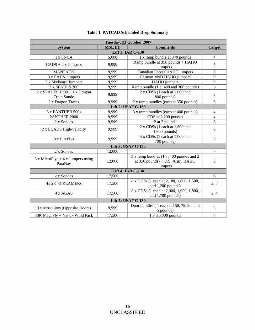
4. Skyboard – Skyboard, Limited Skyboard is a carbon-fiber one-person manned glider that is capable of being deployed from a helicopter or fixed wing aircraft. The system is deployed with front and rear wings folded in. After exit, the wings deploy and allow the pilot to maneuver the glider via aileron and elevator control. The glider includes instrumentation for pilot display including an altimeter, a flight speed indicator and a rate of descent indicator. The system also uses a ballistic parachute for recovery, with the pilot using a personnel parachute for landing. The Skyboard was presented as a static display at PATCAD 2007. The system was planned for airdrops, but approvals were not yet in place at the time of PATCAD. C. Airdrop Support Systems The following systems were demonstrated at PATCAD 07 and used to support airdrop of personnel or cargo. Systems are listed alphabetically by system name. Order is not intended to imply any sort of system ranking. 1. Draper Parafoil Flight Software – Charles Stark Draper Laboratory Draper Lab has developed Guidance, Navigation and Control (GN&C) software for guided parafoil systems. The software uses onboard inertial sensors and GPS data to determine a flight path. It is adaptable to all parafoil weight classes and is United States Government owned software. The guidance algorithm has three phases: homing, energy management and an optimized table-lookup terminal flight phase. It uses a Proportional-Integral-Derivative (PID) controller with feed-forward capability to improve response time. Draper Flight Software was flown on two MicroFly drops and two MegaFly drops. The first Microfly drop with Draper software suffered an inadvertent release from the aircraft, which deployed the systems well beyond the MicroFly Launch Acceptability Region (LAR). The second MicroFly using Draper software did not navigate properly. The MegaFly systems with Draper software both successfully navigated towards the drop zone and landed 939 and 697 meters from the target. 2. Lightweight Composite Enhanced Container Delivery System (ECDS) Platform10 – Triton Systems, Inc. The Lightweight Composite ECDS was designed as a potential replacement for the aluminum ECDS platform. The platform measures 108 inches by 88 inches and is compatible with C-17 and C-130 aerial delivery systems and the C-17 Dual Row Logistics Rails. The majority of the platform is made from advanced composite material that is highly damage and impact tolerant. This material allows for a 20 percent weight reduction from the standard aluminum ECDS platform. Two Lightweight Composite ECDS platforms were used with the 10K Screamer system. This was the first airdrop test of this platform. The total rigged weight (TRW) of each system was 7,950 lbs. The systems were able to be loaded in the aircraft and deployed normally. After the airdrops, the platforms were inspected for damage. No platform damage or delaminating of the composite material was found and the platforms could be re-used. 3. Joint Precision Airdrop Mission Planner (JPADS-MP) – Planning Systems, Inc (PSI), Draper Lab, National Oceanographic and Atmospheric Agency (NOAA) The JPADS-MP11 is a roll-on/roll-off mission planner used to increase the accuracy of ballistic airdrop systems and interface with the AGUs of guided systems. Before an airdrop, a two pound wind sensor, called a Sonde, is dropped. This relays wind information to the aircraft via a UHF signal. This information is combined with wind and weather forecasts to create an updated wind field. The MP software then uses the calculated wind field and known flight characteristics of an airdrop system or personnel parachute to determine the optimal Computed Aerial Release
Figure 26. Draper Lab GN&C
Figure 25. Skyboard on display at the drop zone
Figure 27. Post-drop Composite ECDS Platform
15 UNCLASSIFIED
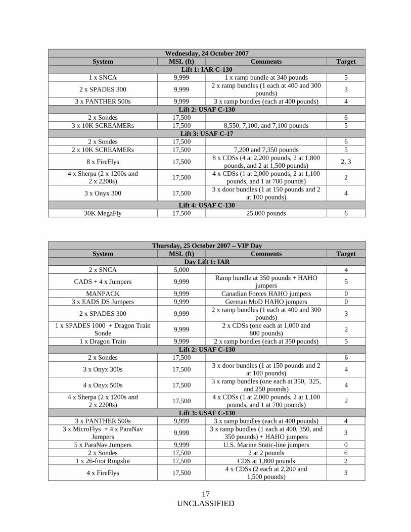
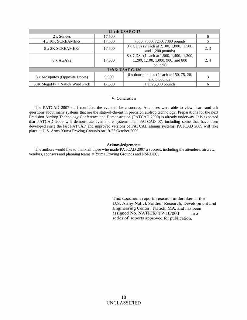
Point (CARP) for ballistic systems or Launch Acceptability Region (LAR) for guided systems. The JPADS-MP also includes a GPS-Retransmission Kit (GPS-RTK) for C-130 and C-17 aircraft. This allows the rebroadcast of the aircraft’s GPS signal into the cargo bay, allowing guided systems to achieve GPS lock in the aircraft. The JPADS-MP was installed and used on two USAF C-130s and the USAF C-17 at PATCAD 2007. Operators successfully used the JPADS-MP to plan and execute guided and unguided airdrops. Wireless updates to integrated AGUs were sent in-flight during PATCAD. 4. Sodar Height Sensor (SHS)12 – Creare, Inc. The Sodar Height Sensor uses acoustic soundings to determine accurate estimates of the height and descent velocity of airdrop systems. The sensor is accurate in its measurements for height above ground level to within two feet, as compared to a vertical GPS error of approximately 60 feet. The SHS can penetrate vegetation, dust, fog and smoke, and has an effective range of up to 500 feet. The system weighs less than four pounds and can transmit height information to an AGU using 802.11 wireless communications. The SHS was used on the Microfly with Draper Flight Software and was included in the flight software loop to successfully trigger a flare. 5. Wireless Gate Release System (WGRS) – Wamore, Inc. The WGRS is an on-aircraft gate release for CDS bundles up to 2,400 lbs. The system uses a Wireless Gate Release Mechanism (WGRM) for each CDS bundle. Each WGRM communicates wirelessly to a Master Control Station (MCS), which the Loadmaster can use to trigger the release of each WGRM. Because the Loadmaster is not required to stand alongside the CDS bundles to manually cut the gates, the WGRS allows C-130 aircraft to carry a full compliment of 16 JPADS loads on a single mission, while maintaining flexibility in drop sequence and order. In Autonomous Mode, the MCS is linked to the JPADS-MP, allowing for the JPADS-MP to command releases with user-defined separation times between payload releases. The Loadmaster is able to emergency stop an autonomous release and take over manual control of the WGRS at any time to maintain aircrew and aircraft safety. The WGRS was used on a C-17 aircraft to release eight 2K Screamer systems from 17,500 ft MSL. The systems released weighed between 1,300 and 2,300 lbs. The C-17 Loadmaster manually triggered the release using the MCS with a three second delay between systems. All WGRMs responded immediately upon commanded release and all releases were successful. D. Results Summary Table 1 shows the aircraft load plan for each day of PATCAD 2007. Full detailed results for each system can be found in the PATCAD 2007 Final Report13.
Figure 28. Block III JPADS-MP
Figure 29. Sodar Height Sensor
Figure 30. WGRS MCS & WGRM
16 UNCLASSIFIED
Table 1. PATCAD Scheduled Drop Summary
Tuesday, 23 October 2007 System MSL (ft) Comments Target
Lift 1: IAR C-130 1 x SNCA 5,000 1 x ramp bundle at 340 pounds 4
CADS + 4 x Jumpers 9,999 Ramp bundle at 350 pounds + HAHO
jumpers 5
MANPACK 9,999 Canadian Forces HAHO jumpers 0 3 x EADS Jumpers 9,999 German MoD HAHO jumpers 0
2 x Skyboard Jumpers 9,999 HAHO jumpers 0 2 x SPADES 300 9,999 Ramp bundle (1 at 400 and 300 pounds) 3
2 x SPADES 1000 + 1 x Dragon Train Sonde
9,999 2 x CDSs (1 each at 1,000 and
800 pounds) 2
2 x Dragon Trains 9,999 2 x ramp bundles (each at 350 pounds) 5 Lift 2: USAF C-130
3 x PANTHER 500s 9,999 3 x ramp bundles (each at 400 pounds) 4 PANTHER 2000 9,999 CDS at 2,200 pounds 4
2 x Sondes 9,999 2 at 2 pounds 6
2 x LCADS High-velocity 9,999 2 x CDSs (1 each at 1,800 and
1,600 pounds) 5
3 x FireFlys 9,999 4 x CDSs (2 each at 1,000 and
700 pounds) 3
Lift 3: USAF C-130 2 x Sondes 12,000 6
3 x MicroFlys + 4 x Jumpers using ParaNav
12,000 3 x ramp bundles (1 at 400 pounds and 2
at 350 pounds) + U.S. Army HAHO jumpers
3
Lift 4: IAR C-130 2 x Sondes 17,500 6
4x 2K SCREAMERs 17,500 8 x CDSs (1 each at 2,100, 1,800, 1,500,
and 1,200 pounds) 2, 3
4 x AGAS 17,500 8 x CDSs (1 each at 2,000, 1,900, 1,800,
and 1,700 pounds) 2, 4
Lift 5: USAF C-130
3 x Mosquitos (Opposite Doors) 9,999 Door bundles ( 1 each at 150, 75, 20, and
5 pounds) 3
30K MegaFly + Natick Wind Pack 17,500 1 at 25,000 pounds 6
17 UNCLASSIFIED
Wednesday, 24 October 2007 System MSL (ft) Comments Target
Lift 1: IAR C-130 1 x SNCA 9,999 1 x ramp bundle at 340 pounds 5
2 x SPADES 300 9,999 2 x ramp bundles (1 each at 400 and 300
pounds) 3
3 x PANTHER 500s 9,999 3 x ramp bundles (each at 400 pounds) 4 Lift 2: USAF C-130
2 x Sondes 17,500 6 3 x 10K SCREAMERs 17,500 8,550, 7,100, and 7,100 pounds 5
Lift 3: USAF C-17 2 x Sondes 17,500 6
2 x 10K SCREAMERs 17,500 7,200 and 7,350 pounds 5
8 x FireFlys 17,500 8 x CDSs (4 at 2,200 pounds, 2 at 1,800
pounds, and 2 at 1,500 pounds) 2, 3
4 x Sherpa (2 x 1200s and 2 x 2200s)
17,500 4 x CDSs (1 at 2,000 pounds, 2 at 1,100
pounds, and 1 at 700 pounds) 2
3 x Onyx 300 17,500 3 x door bundles (1 at 150 pounds and 2
at 100 pounds) 4
Lift 4: USAF C-130 30K MegaFly 17,500 25,000 pounds 6
Thursday, 25 October 2007 – VIP Day System MSL (ft) Comments Target
Day Lift 1: IAR 2 x SNCA 5,000 4
CADS + 4 x Jumpers 9,999 Ramp bundle at 350 pounds + HAHO
jumpers 5
MANPACK 9,999 Canadian Forces HAHO jumpers 0 3 x EADS DS Jumpers 9,999 German MoD HAHO jumpers 0
2 x SPADES 300 9,999 2 x ramp bundles (1 each at 400 and 300
pounds) 3
1 x SPADES 1000 + Dragon Train Sonde
9,999 2 x CDSs (one each at 1,000 and
800 pounds) 2
1 x Dragon Train 9,999 2 x ramp bundles (each at 350 pounds) 5 Lift 2: USAF C-130
2 x Sondes 17,500 6
3 x Onyx 300s 17,500 3 x door bundles (1 at 150 pounds and 2
at 100 pounds) 4
4 x Onyx 500s 17,500 3 x ramp bundles (one each at 350, 325,
and 250 pounds) 4
4 x Sherpa (2 x 1200s and 2 x 2200s)
17,500 4 x CDSs (1 at 2,000 pounds, 2 at 1,100
pounds, and 1 at 700 pounds) 2
Lift 3: USAF C-130 3 x PANTHER 500s 9,999 3 x ramp bundles (each at 400 pounds) 4
3 x MicroFlys + 4 x ParaNav Jumpers
9,999 3 x ramp bundles (1 each at 400, 350, and
350 pounds) + HAHO jumpers 3
5 x ParaNav Jumpers 9,999 U.S. Marine Static-line jumpers 0 2 x Sondes 17,500 2 at 2 pounds 6
1 x 26-foot Ringslot 17,500 CDS at 1,800 pounds 2
4 x FireFlys 17,500 4 x CDSs (2 each at 2,200 and
1,500 pounds) 3
18 UNCLASSIFIED
Lift 4: USAF C-17 2 x Sondes 17,500 6
4 x 10K SCREAMERs 17,500 7050, 7300, 7250, 7300 pounds 5
8 x 2K SCREAMERs 17,500 8 x CDSs (2 each at 2,100, 1,800, 1,500,
and 1,200 pounds) 2, 3
8 x AGASs 17,500 8 x CDSs (1 each at 1,500, 1,400, 1,300,
1,200, 1,100, 1,000, 900, and 800 pounds)
2, 4
Lift 5: USAF C-130
3 x Mosquitos (Opposite Doors) 9,999 8 x door bundles (2 each at 150, 75, 20,
and 5 pounds) 3
30K MegaFly + Natick Wind Pack 17,500 1 at 25,000 pounds 6
V. Conclusion
The PATCAD 2007 staff considers the event to be a success. Attendees were able to view, learn and ask questions about many systems that are the state-of-the-art in precision airdrop technology. Preparations for the next Precision Airdrop Technology Conference and Demonstration (PATCAD 2009) is already underway. It is expected that PATCAD 2009 will demonstrate even more systems than PATCAD 07, including some that have been developed since the last PATCAD and improved versions of PATCAD alumni systems. PATCAD 2009 will take place at U.S. Army Yuma Proving Grounds on 19-22 October 2009.
Acknowledgements The authors would like to thank all those who made PATCAD 2007 a success, including the attendees, aircrew, vendors, sponsors and planning teams at Yuma Proving Grounds and NSRDEC.
TP-10/003
19 UNCLASSIFIED
References 1 J. McHugh, R. Benney, J. Miletti, P. Mortaloni, "Planning, Execution, and Results of the Precision Airdrop Technology Conference and Demonstration (2003)," AIAA Aerodynamic Decelerator Systems Conference, May 23-26 2005, Munich, Germany. 2 U.S. Army Natick Soldier Research, Development and Engineering Center, “Precision Airdrop Technology Conference and Demonstration 2005 Final Report,” 2005. 3 Army Regulation 385-16. System Safety Management Guide. 1987. 4 Dunker, S.. “Modularity Concepts for a 30,000 lbs Capacity Ram-Air Parachute,” AIAA Aerodynamic Decelerators Conference, May 21-24 2007, Williamsburg, VA. 5 Hattis, P., “Autonomous Large Parafoil Guidance, Navigation and Control System Design Status,” AIAA Aerodynamic Decelerators Conference, May 21-24 2007, Williamsburg, VA. 6 Calise, A., “Modeling for Guidance and Control Design of Autonomous Guided Parafoils,” AIAA Aerodynamic Decelerators Conference, May 21-24 2007, Williamsburg, VA. 7 McGrath, J., Strong, E., & Benney, a. R., “Status of the Development of an Autonomously Guided Precision Cargo Aerial Delivery System,” AIAA Aerodynamic Decelerators Conference, May 23-26 2005, Munich, Germany. 8 Benney, R. e., “The Joint Precision Airdrop System Advanced Concept Technology Demonstration,” AIAA Aerodynamic Decelerators Conference, May 23-26 2005, Munich, Germany. 9 Wegereef, J., “Modular Approach of Precision Airdrop System SPADES,” AIAA Aerodynamic Decelerators Conference, May 21-24 2007, Williamsburg, VA. 10 Alexander, J., “Affordable and Lightweight Composite Airdrop Platform,” AIAA Aerodynamic Decelerators Conference, May 21-24 2007, Williamsburg, VA. 11 Wright, R., Benney, R., & McHugh, a. J., “Precision Airdrop System,” AIAA Aerodynamic Decelerators Conference, May 21-24 2007, Williamsburg, VA. 12 Dietz, A., “A Sodar Height Sensor for Precision Airdrop,” AIAA Aerodynamic Decelerators Conference, May 21-24 2007, Williamsburg, VA. 13 U.S. Army Natick Soldier Research, Development and Engineering Center. “Precision Airdrop Technology Conference and Demonstration 2007,” February 2008.