precautions - tc...
TRANSCRIPT
1
PRECAUTIONS !
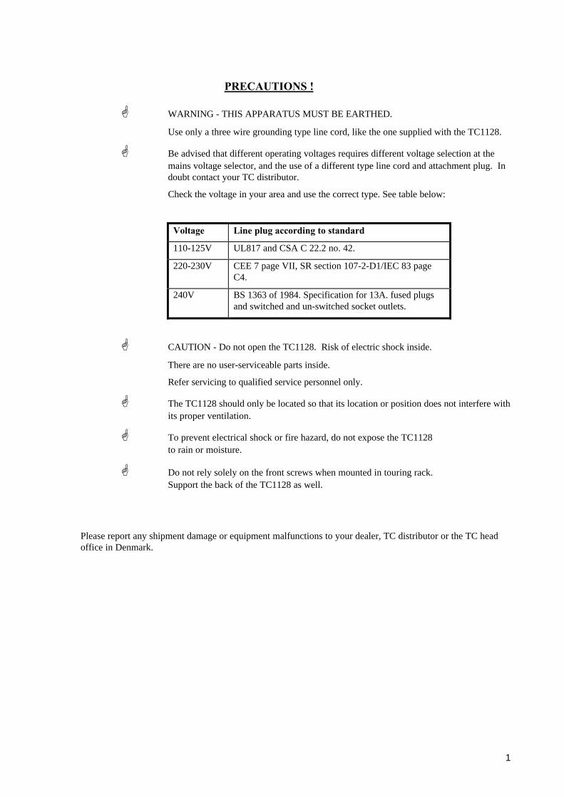
G WARNING - THIS APPARATUS MUST BE EARTHED.
Use only a three wire grounding type line cord, like the one supplied with the TC1128.
G Be advised that different operating voltages requires different voltage selection at themains voltage selector, and the use of a different type line cord and attachment plug. Indoubt contact your TC distributor.
Check the voltage in your area and use the correct type. See table below:
Voltage Line plug according to standard
110-125V UL817 and CSA C 22.2 no. 42.
220-230V CEE 7 page VII, SR section 107-2-D1/IEC 83 pageC4.
240V BS 1363 of 1984. Specification for 13A. fused plugsand switched and un-switched socket outlets.
G CAUTION - Do not open the TC1128. Risk of electric shock inside.
There are no user-serviceable parts inside.
Refer servicing to qualified service personnel only.
G The TC1128 should only be located so that its location or position does not interfere withits proper ventilation.
G To prevent electrical shock or fire hazard, do not expose the TC1128 to rain or moisture.
G Do not rely solely on the front screws when mounted in touring rack. Support the back of the TC1128 as well.
Please report any shipment damage or equipment malfunctions to your dealer, TC distributor or the TC headoffice in Denmark.

2
NOTE:
This equipment has been tested and found to comply with the limits for a Class B digital device, pursuant to part 15 of the FCC rules.These limits are designed to provide reasonable protection against harmful interference in a residential installations.This equipment generates, uses and can radiate radio frequency energy and, if not installed and used in accordance with the instructions,may cause harmful interference to radio communications. However, there is no guarantee that interference will not occur in a particularinstallation. If this equipment does cause harmful interference to radio or television reception, which can be determined by turning theequipment off and on, the user is encouraged to try to correct the interference by one or more of the following measures:
- Reorient or relocate the receiving antenna.
- Increase the separation between the equipment and receiver.
- Connect the equipment into an outlet on a circuit different from that to which the receiver is connected.
- Consult the dealer or an experienced radio/TV technician for help.
The user may find the following booklet prepared by the Federal Communications Commission helpful:
"How to identify and Resolve Radio/TV interference Problems."
This booklet is available from the US. Government Printing Office, Washington, DC 20402, Stock No. 004-000-0034-4.
Caution:
You are cautioned that any change or modifications not expressly approved in this manual could void your authority to operate thisequipment.
For the customers in Canada:
This Class B digital apparatus meets all requirements of the Canadian Interference-Causing Equipment Regulations.Cet appareil numérique de la classe B respecte toutes les exigences du Réglement sur le matériel brouilleur du Canada.
Certificate Of Conformity
TC Electronic A/S, Grimhøjvej 3, 8220 Brabrand, Denmark, hereby declares on own responsibility that following product:
TC 1128 Programmable 28 Band Graphic Equalizer / Spectrum Analyser
That is covered by this certificate and marked with CE-label conforms with following standards:
EN 60065 (IEC 65) Safety requirements for mains operated electronic and related apparatus for household and similar general use.
EN 50081-1 Electromagnetic compatibility - Generic emission standard - Part 1: Residential, commercial and light industry.
EN 50082-1 Electromagnetic compatibility - Generic immunity standard - Part 1: Residential, commercial and light industry.
With reference to regulations in following directives:
73/23/EEC, 89/336/EEC
Issued in Brabrand, February 8. 1996
Anders FauerskovChief Executive Officer
3
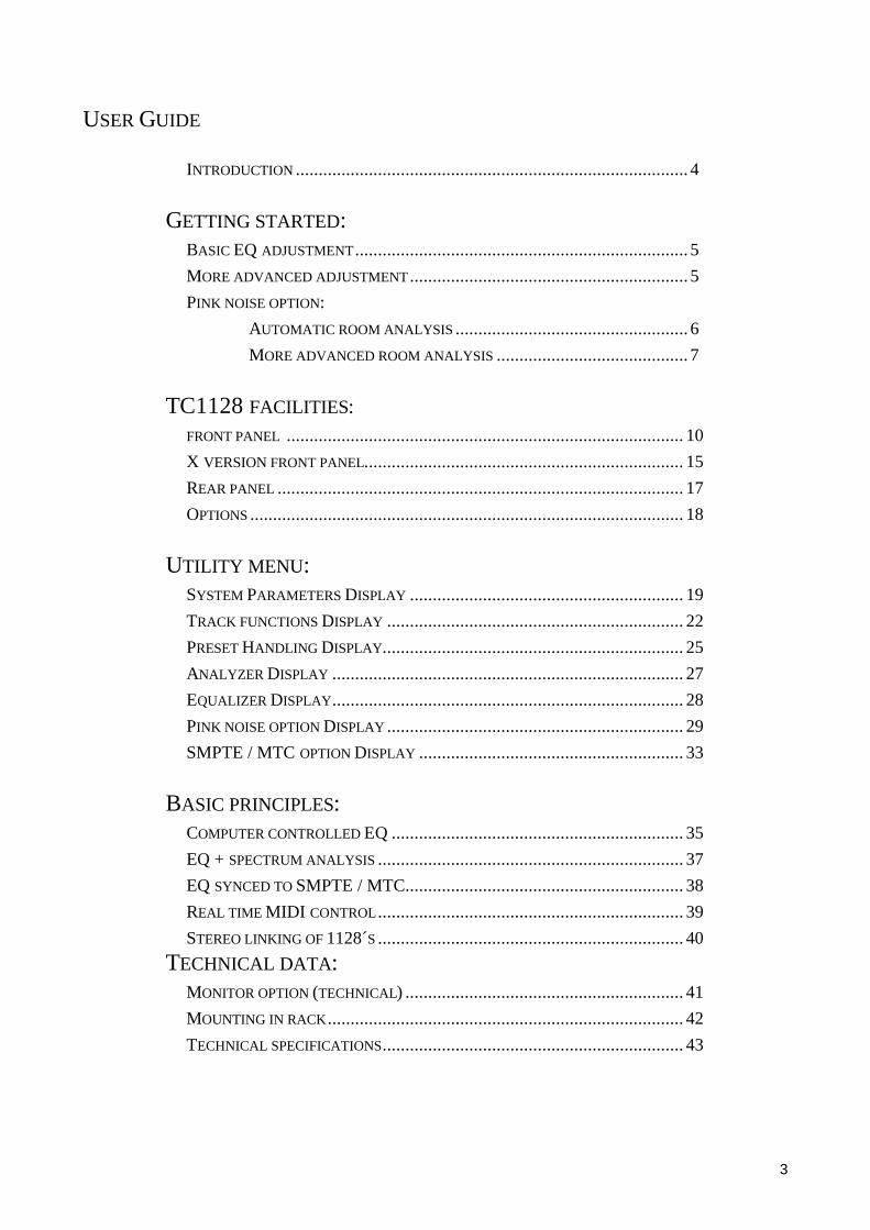
USER GUIDE
INTRODUCTION ...................................................................................... 4
GETTING STARTED:BASIC EQ ADJUSTMENT ......................................................................... 5
MORE ADVANCED ADJUSTMENT ............................................................. 5
PINK NOISE OPTION:
AUTOMATIC ROOM ANALYSIS ................................................... 6
MORE ADVANCED ROOM ANALYSIS .......................................... 7
TC1128 FACILITIES:FRONT PANEL ....................................................................................... 10
X VERSION FRONT PANEL...................................................................... 15
REAR PANEL ......................................................................................... 17
OPTIONS ............................................................................................... 18
UTILITY MENU:SYSTEM PARAMETERS DISPLAY ............................................................ 19
TRACK FUNCTIONS DISPLAY ................................................................. 22
PRESET HANDLING DISPLAY.................................................................. 25
ANALYZER DISPLAY ............................................................................. 27
EQUALIZER DISPLAY............................................................................. 28
PINK NOISE OPTION DISPLAY ................................................................. 29
SMPTE / MTC OPTION DISPLAY .......................................................... 33
BASIC PRINCIPLES:COMPUTER CONTROLLED EQ ................................................................ 35
EQ + SPECTRUM ANALYSIS ................................................................... 37
EQ SYNCED TO SMPTE / MTC............................................................. 38
REAL TIME MIDI CONTROL ................................................................... 39
STEREO LINKING OF 1128´S ................................................................... 40
TECHNICAL DATA:MONITOR OPTION (TECHNICAL) ............................................................. 41
MOUNTING IN RACK .............................................................................. 42
TECHNICAL SPECIFICATIONS.................................................................. 43

4
INTRODUCTION
Congratulations on your purchase of the worlds most versatile equalizer! TheTC1128/TC1128X offers features and applications that have never been availablebefore... this means that some of the concepts explained in this manual will be new toyou. We can only ask you to set some time aside for experimenting with the TC1128/TC1128X in your system. The absolute top sound engineers in the world have takenthe time to understand the power of the TC1128/TC1128X and they have applied thistechnology in new and unique ways! The option selection and complimentary productsfor this equalizer gives you a multitude of variations to match just your application andwe hope that you can learn the world of computer controlled audio and can apply thispowerful work tool to solve your audio challenges!

5
GETTING STARTED
BASIC EQ ADJUSTMENT
1. Make sure SWEEP and TRACK LED indicators are off.
2. Press DISPLAY if the display is not currently showing the EQ settings.
3. Press FILTER, and then SINGLE.
4. Use the dial PUSH ENTER knob to make eq settings by turning the knob to select an eq band. Notice that the frequency is shown at the bottom of the display. When you push and turn the knob at the same time, you adjust boost/cut and a fader appears visualizing the position. The exact dB value is shown on the bottom line.
5. As you are turning this knob the frequency content of the audio signal is being changed. Repeat the selection process to adjust other frequency bands.
MORE ADVANCED ADJUSTMENT
1. Press the FLAT key to start a new EQ curve.
2. This time, press the BROAD key instead of the SINGLE key. Turn to a frequency band near the center of the display and turn the PUSH ENTER knob clockwise while holding it pushed in... a "wave" of frequencies will be boosted.
3. Try also the LOW and HIGH shelving keys
4. Notice as long as you are at the same frequency, you can switch between the different contours.
Now let's try doing a parametric approach:
1. Press the SWEEP key.
2. To make an eq setting of +8dB at 1kHz : press FLAT, turn the PUSH ENTER knob to 1kHz. Push in and hold in while turning up to +8dB
3. Notice now as you release the PUSH ENTER knob you are able to sweep up anddown the frequency spectrum by turning the knob left or right.
4. To store the current setting, press the PUSH ENTER knob twice or pressFILTER.
Setting the LEVEL:
The LEVEL appears as the 29th.(wider) band on the far right hand side of the display.In FILTER mode, simply turn the cursor to this band and change as any other band.LEVEL is used for matching the volume of the preset with the volume of by-pass ("eqoff").

6
PINK NOISE OPTION
AUTOMATIC ROOM ANALYSIS
To perform an 1 position room analysis, you can follow the procedure below. Amore detailed description of the parameters is found in the PINK NOISE menudescription.
1. Turn power off and then on again. This makes sure that "old" measurements are erased from the memory and MEASUREMENT NO: is reset.
2. Connect a microphone with a relatively flat frequency response to the INPUT JACK using a stereo 1/4" jack. For connection details refer to the REAR PANELdescription. The pink noise will be output via the jack- and XLR-output. This should and normally will be connected to your power amplifier and speaker system.
3. Enter the UTILITY menu and select the PINK NOISE OPTION menu.
4. If needed, scroll down and turn on PHANTOM POWER for the microphone you are using.
5. Set the PINK NOISE menu settings as follows (factory default settings):comments
MEASUREMENT NO. : 00 first measurementRESULT 1 WEIGHT : 00 (= off)RESULT 2 WEIGHT : 00 (= off)RESULT 3 WEIGHT : 00 (= off)RESULT 4 WEIGHT : 00 (= off)AUTOLIN METHOD : SWEEP/PARAL(experiment !)TARGET RESPONSE : 00 (= off)MIC AUTOSET : ON auto level adjustment of micamp.MIC RESPONSE PRE : 00 (= off)
6. Physically locate the test microphone where you want to measure. One ssuggestion is to place it in a good listening position.
7. Select START AUTOLIN 1 on top of the PINK NOISE menu and press PUSH ENTER.
8. If you find the pink noise level insufficient (LEVEL TOO LOW); enter the PINK NOISE menu again and adjust NOISE LEVEL briefly. You might use PINK NOISE ONLY = ON to adjust NOISE LEVEL.

7
9. When the measurement is finished, press the STORE button and turn the PUSH ENTER knob to a preset number you can overwrite. Press the PUSH ENTER knob in and the measurement is now stored into this preset number location. Exit STORE mode by pressing the FILTER key.
Now you can compare the result before and after the measurement. Simply playsome music through the equalizer and toggle the EQ ON button. If you're notsatisfied you can do this procedure over and over again moving the test microphoneto different locations. In the beginning don't hesitate to experiment with SWEEP orPARALLEL methods. You will find a noticeable difference between the 2 methods.IN THE END - TRUST YOUR EARS !
AN ACCURATE ACOUSTIC RESPONSE HAS NEVER BEEN EASIER !
Everytime you start a new measurement just use START AUTOLIN 1 and store themeasurements in different presets. You can then afterwards always recall thedifferent measurements while listening to the music through the equalizer.
REMEMBER: The physical location of the microphone is the only variablewith this method and essential for the result of the measurement. Don't beafraid of experimenting in order for you to find the best and easiest procedure.
"MORE ADVANCED ROOM ANALYSIS "
To perform an 4 position room analysis, you need to:
1. Turn power off and then start again. This makes sure that "old" measurements areerased from the memory and MEASUREMENT NO: is reset.
2. Connect a microphone with a relatively flat frequency response to the INPUT JACK using a stereo 1/4" jack. For connection detail refer to the REAR PANEL description. The pink noise will be output through the OUTPUT JACK and XLR.
3. Enter the UTILITY menu and select the PINK NOISE OPTION menu.
4. Turn on PHANTOM POWER if needed for the microphone in use.
8
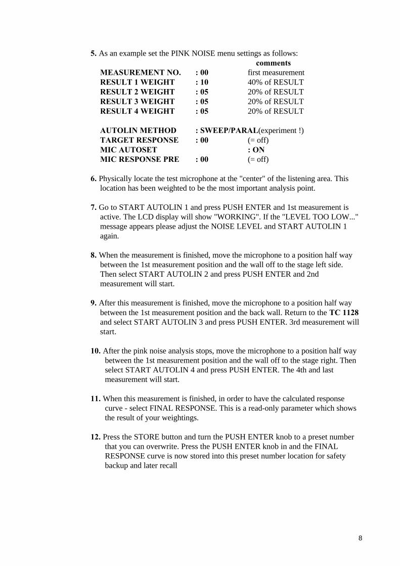
5. As an example set the PINK NOISE menu settings as follows:comments
MEASUREMENT NO. : 00 first measurementRESULT 1 WEIGHT : 10 40% of RESULTRESULT 2 WEIGHT : 05 20% of RESULTRESULT 3 WEIGHT : 05 20% of RESULTRESULT 4 WEIGHT : 05 20% of RESULT
AUTOLIN METHOD : SWEEP/PARAL(experiment !)TARGET RESPONSE : 00 (= off)MIC AUTOSET : ONMIC RESPONSE PRE : 00 (= off)
6. Physically locate the test microphone at the "center" of the listening area. This location has been weighted to be the most important analysis point.
7. Go to START AUTOLIN 1 and press PUSH ENTER and 1st measurement is active. The LCD display will show "WORKING". If the "LEVEL TOO LOW..." message appears please adjust the NOISE LEVEL and START AUTOLIN 1 again.
8. When the measurement is finished, move the microphone to a position half way between the 1st measurement position and the wall off to the stage left side. Then select START AUTOLIN 2 and press PUSH ENTER and 2nd measurement will start.
9. After this measurement is finished, move the microphone to a position half way between the 1st measurement position and the back wall. Return to the TC 1128and select START AUTOLIN 3 and press PUSH ENTER. 3rd measurement will start.
10. After the pink noise analysis stops, move the microphone to a position half way between the 1st measurement position and the wall off to the stage right. Then select START AUTOLIN 4 and press PUSH ENTER. The 4th and last measurement will start.
11. When this measurement is finished, in order to have the calculated response curve - select FINAL RESPONSE. This is a read-only parameter which shows the result of your weightings.
12. Press the STORE button and turn the PUSH ENTER knob to a preset number that you can overwrite. Press the PUSH ENTER knob in and the FINAL RESPONSE curve is now stored into this preset number location for safety backup and later recall

9
You now have an example of a reference curve for this acoustic space that ismore accurate than any analysis you could have done with many pieces ofequipment and many hours of setup !! Notice that the time taken to do thiscomplete analysis is approximately 10-20 minutes depending on measurementsmethods!
13. A tip for permanent installations: Copy and STORE your reference curve intothe display and then pressing STORE. Turn the PUSH ENTER knob to another preset number that you can overwrite and then press the PUSH ENTERknob in. The original EQ curve is now copied to the new preset number. Repeatthis many times so you have many presets that can be modified and compared quickly. Experiment with modifications to these EQ settings with different program material. You will soon have preferred curves for different types of music, different sizes of crowds, different temperatures, different sound engineers, etc.

10
DESCRIPTION OF TC 1128 FRONT PANEL
1. POWER
A few seconds after you turn on the POWER, the display will show the startupscreen with the software version number. After a short delay, you will hear the by-pass relays activate which sends the audio signal through the device. Should powerbe lost during a performance, the XLR inputs are connected to the XLR outputsautomatically by these relays.
2. INPUT GAIN
Press this button to select the input gain. Adjust it by using the PUSH ENTER knob.You can see the gain of the input signal as you turn the knob. Clipping of the inputis indicated on the spectrum analyzer bar graphs by segments "disappearing" at thebottom of a fully illuminated bar graph. Adjust the gain for maximum signal withoutclipping indication.
3. EQ ON
This is a software controlled by-pass function which electrically by-passes theequalizer circuitry.
4. FREEZE
Press FREEZE to stop the analyzer display so that you can see the frequencycontent of the signal. Pressing FREEZE once again will return the spectrum displayto real time viewing. In the UTILITY menu - ANALYZER SETUP you canprogram the analyzer to show the input (pre EQ) or the output (post EQ). TheTRACK FUNCTIONS menu allows you to program the TRACK button so that aninverse EQ setting is automatically generated based on a pre-EQ FREEZE spectrumresponse so that a post-EQ flat frequency response is obtained. This function iscalled ALIGN SA RESP. Refer to the TRACK FUNCTION DISPLAY forexplanation.
5. 1 - 99 (preset number)
The 99 presets store the EQ boost/cut settings for the 28 frequency bands and theinput and output gain settings. The input gain settings can be set so that they are notactivated upon recall (see the PRESET HANDLING DISPLAY section for moreinformation). When previewing presets, the 1-99 number will blink meaning that thispreset is being displayed but is not being applied to the audio signal. When thedisplay is not blinking, this preset is applied to the audio path. NOTE: TheUTILITY menu - PRESET HANDLING allows presets to be labeled, protectedagainst overwrite, and downloaded to other devices or for permanent storage.
6. GRAPHICS LCD DISPLAY
The LCD (liquid crystal display) is a critical part of the TC 1128 user interface. Theability to show real time spectrum response, draw frequency curves and write largeamounts of text information is what makes this equalizer so powerful and easy tounderstand !

11
7. OVERLOAD LED INDICATOR
Overload indication shows if any of the internal circuits are being over driven. Inputgain should be set for occasional indication.
8. TRACK LED INDICATOR
The TRACK LED is able to show MIDI input data or valid timecode indication. Thesetup for this indicator is in the UTILITY MENU - TRACK FUCTIONS display.
9. DISPLAY
The DISPLAY key cycles between three types of display on the LCD:
1. EQ & ANALYZER simultaneously2. EQ ONLY (full screen)3. ANALYZER ONLY (full screen)
10. FLAT
Sets all frequency bands flat (no boost or cut). Audio still passes through the gainand equalizer circuitry. This key can be disabled (locked) against accidental usageunder the UTILITY menu - SYS PARAMETERS.
11. TRACK
The TRACK button is a programmable function key. The functions to be controlledby this button are set in the UTILITY menu - TRACK FUNCTIONS DISPLAYsection.
12. SWEEP
Make a parametric setting. Whatever curve contour you have chosen you will beable to sweep the curve through the 28 bands. To keep the current eq setting turnoff SWEEP or PUSH ENTER twice quickly (reffered to as doubleclick in thefollowing).
CURVE EDIT CONTOUR KEYS
Four keys allowing you to adjust one or several faders at a time. With several faders,the faders follow a predefined contour:
13. SINGLE BAND
Single fader adjustment similar to the adjustment of a single fader on a standard 1/3octave graphic equalizer.
14. BROAD BAND
Adjust more than a single band. This functions similar to a parametric equalizer sothat adjustments are done in "waves" of frequency changes. To see how this works,press the FLAT key once so you have no EQ setting, then press the BROAD key.Press and turn the PUSH ENTER knob (while holding in) and you will see a curveof filters. The response of this curve can be selected as either 3dB, 6dB, 9dB, 12dBper octave preselected in the UTILITY menu - EQUALIZER SET-UP, or press andhold the BROAD key while dialing the PUSH ENTER.

12
15. LOW SHELVING
Boost or cut of all frequencies lower than the selected band.
16. HIGH SHELVING
Boost or cut of all frequencies higher than the selected band.
PRESET HANDLING KEYS
There are 3 selection buttons which are used for activating EQ settings, placingthem into the TC1128´s memory or combining EQ curve settings. Refer to theUTILITY menu - PRESET HANDLING to see even more features:
17. RECALL
The first press on the RECALL button enables the PUSH ENTER knob to controlthe viewing of the EQ settings that are in the 01-99 memories. There is no change tothe audio signal while scrolling thru the memories until you press the PUSH ENTERknob in to select the displayed EQ memory. If you hold the PUSH ENTER knob inwhile turning, the EQ memories will be activated (change audio response)immediately as you scroll.
Exit RECALL mode by pressing the FILTER button.
18. ADD
If you want to combine the current EQ settings with EQ settings from one of the 01-99 memories, press ADD and select the 01-99 memory and then press the PUSHENTER knob in. This combining of settings is useful if you want to compensate forroom acoustics or microphone characteristics... just add the measurement curve tothe modification that you feel sounds best.
If two curves added together are greater than the maximum dB range, the settingwill be limited to the maximum dB.
Exit the ADD mode by pressing the FILTER button.
19. STORE
By pressing the STORE button you can turn the PUSH ENTER knob to the 01-99memory number that you want an EQ setting to be stored in. When you press thePUSH ENTER knob in, the setting is then stored in memory. Preset labeling,inclusion of input gain, memory protect, and dumping of memories via MIDI areavailable in the UTILITY menu PRESET HANDLING.

13
20. UTIL
Press the UTIL (Utility) button to enter the menu system on the front panel LCD (ormonitor option). Setup parameters are as follows (the parameters are explained inthe UTILITY MENU section:
SYSTEM PARAMETERS
PINK NOISE OPTION
TRACK FUNCTIONS
PRESET HANDLING
ANALYZER SETUP
EQUALIZER SETUP
Return to the UTILITY main menu by pressing the UTILITY button again or exitthe UTILITY menu by pressing the FILTER button.
21. FILTER
This button is used to put the unit back into the normal "edit ready" mode. Forexample, if you are in the utilities menu and want to get back to adjusting the EQ,then press FILTER the unit will return to the last display mode.
22. PUSH ENTER
The PUSH ENTER button is used to make adjustments. Push and turn it clockwiseto increase values and counter clockwise to decrease values.
MINOR RESET
COMMAND = hold PUSH ENTER 10 sec's or until you hear the bypass relaysactivate at power on, and press the DISPLAY button. It's very impotant that youremember to press DISPLAY as it then initializes the parameters and confirms thereset.
This reset will zero some common parameters but will not effect the EQ presets inmemory. This reset is used if for any reason there is a partial microprocessor failure,for example from power line spikes, etc. This will also allow you to "open" asecurity locked unit if you have forgotten the programmed lock combination (see theSYSTEM PARAMETERS DISPLAY explanation).
WARNING: THE MEMORY PROTECT SETTING IS SET OFF SO TURNIT ON AGAIN IF NEEDED !

14
MAJOR RESET
COMMAND = press FLAT and STORE 5 sec's or until you hear the bypass relaysactivate at power on, and press the DISPLAY button.
After you have turned the power on, the display will show "PRESET STORE ". Ifyou don't press the DISPLAY button the LCD will show "ALL PARAMETERSINITIALIZED". Then press DISPLAY. Your TC1128 is now in its standard factorysetup. This reset is used if you want to erase all previously set parameters, forexample if you are using the TC1128 in a rental situation.
ALL PRESETS ARE LOST !

15
DESCRIPTION OF TC1128X FRONT PANEL
1. POWER ON / OFF
When power is first applied, the 7-segment display will briefly show the MIDIdevice number that has been assigned to the unit. This is useful if you have multipleunits so you can see that all devices are set to function together.
2. PRESET
The first time you press PRESET, the 01-99 display will show the eq preset that isnow active and the UP and DOWN keys can cycle through the preset numbers. Thesecond time you press PRESET, the EQ ON and ON LINE keys will function. The01-99 display will show "- -" which shows that the PRESET mode is not active rightnow.
3. EQ ON
This is a bypass function which removes the audio signal from the equalizer circuit.The 01-99 display must be showing "- -" for this function to be accessed. Toggle thePRESET key to get out of PRESET display mode if necessary.
4. ON LINE
This key determines if the TC1128X should listen to the MIDI communications portor not. For example, when connected together with another TC1128 as a stereopair, you can adjust them together, then take the SLAVE unit OFF LINE and makefinal adjustments to the MASTER unit without effecting the SLAVE. The LEDindicator MUST show ON LINE for external communications with other TC1128´sor computer control (EQTALK program).
5. 01 - 99 ( PRESETS)
There can be 99 eq memories stored in the TC1128X. After programming thefrequency response using another TC1128 or an external device, a user only needscontrol over the PRESET number to activate the memory. For example, a curve canbe stored for "theater" acoustics, and another curve can be stored for "pop music"acoustics. A non-technical user needs just to remember to select preset 1 or preset 2
6. OVERLOAD LED INDICATOR
Overload indication shows if any of the internal circuits are being over driven. Thegain adjustment must be made by a master TC1128, an external computer(EQTALK), or the TC6032 motor fader REMOTE.
7. TRACK LED INDICATOR
This flashes when MIDI communication is taking place. For example, in a stereosetup the MIDI communication takes place roughly once every 2 seconds, andimmediately when changes are made.

16
NEW DEVICE NUMBER:
Turn the power on while holding the PRESET button depressed. The numbers onthe 01-99 display will begin to flash the default MIDI device number. You can nowuse the UP/DOWN buttons to select the desired number. Press the PRESET buttonagain, and the number will be stored and the display will return to normal.
MINOR RESET
Hold the PRESET key depressed for 5 seconds when powering up. Turn power offagain and back on and all parameters are now set to their default value. This will noterase the presets stored in memory.
MAJOR RESET
A major reset is not possible, however all presets can be overwritten by performing aMIDI EXCLUSIVE DUMP of data from an "empty" TC1128 to the TC1128X.Connect the TC1128 MIDI OUT to the TC1128X MIDI IN and activate the MIDIEXCL. DUMP selection under the UTILITY menu - PRESET HANDLING.

17
REAR PANEL CONNECTORS
INPUT JACK ...............................................................................unbalanced 1/4 " jack socket
- when PINK NOISE OPTION is installed, this is a balanced micro-phone input (stereo connection with phantom power = + 48v DC).
OUTPUT JACK ...........................................................................unbalanced 1/4 " jack socket
INPUT XLR ...................................................................................................... Pin 1 = groundPin 2 = hotPin 3 = cold
OUTPUT XLR ...................................................................................................Pin 1 = groundPin 2 = hotPin 3 = cold
- NOTE: connection from XLR input to output is made automatically upon power loss.
MIDI OUTPUT ........................................................................................ 5 pin DIN connector
MIDI INPUT ............................................................................................5 pin DIN connector
MIDI THRU .............................................................................................5 pin DIN connector
ASSIGN SWITCH .............................1/4 " jack socket for TC 0050 (5 switches + 4 resistors)
- when SMPTE/MTC option is installed, a stereo jack is connectedhere for SMPTE input/output, TIP = IN, RING = OUT.
TC LINK ........................................... 1/4 " jack socket for connection to TC 0144 foot controller.
MONITOR OPTION RGB OUTPUT..........................................................9 pin D connector
pin 1: ground pin 6: intensitypin 2: not connected pin 7: not connectedpin 3: blue ( B ) pin 8: horiz. syncpin 4: red ( R ) pin 9: vert. syncpin 5: green ( G )
MONITOR OPTION VIDEO OUTPUT .....................................................RCA jack socket(internal jumper for PAL or NTSC)
MONITOR OPTION RS 232 MOUSE ........................................................not implemented

18
TC1128 OPTIONS
Here is a list of the options for the TC1128:
1. PINK NOISE - generator + microphone input + analysis software for automaticacoustic equalization
2. RGB MONITOR OUTPUT - RGB and video output for displaying the front panelLCD on a large screen.
3. SMPTE/MIDI TIME CODE - software addition for synchronizing preset changesto timecode.
4. +/- 16 dB BOOST/CUT RANGE - additional upgrade circuitry for larger EQrange. This requires PC99 or Mac99 or TC6032 for proper viewing.
5. REMPAL - required in order to communicate with TC6032.
NOTE: PINK NOISE and SMPTE options can not be mounted in the same unit atthe same time.
NOTE: PINK NOISE option can not be installed in +/- 16 dB versions.’
TC1128X OPTIONS
The X version is primarily used as a slave device for a TC1128 when used for liveacoustic analysis or stereo operation, so the PINK NOISE, SMPTE, andMONITOR options must be mounted in the standard TC1128 and not in the Xversion.
1. REMPAL - required in order to communicate with TC6032.
2. +/- 16 dB BOOST/CUT RANGE upgrade.
REMOTE CONTROL OPTIONS:
1. EQTALK; PC (PC99) or MacIntosh (MAC99) dedicated control software
2. PCMIDI - MIDI card for PC computers
3. PCM99 - an external MIDI interface for serial computer ports
4. TC6032 motor fader remote controller + MM24 MIDI Matrix, which allows theTC6032 to control up to 32 TC1128/TC1128Xs
5. MIDI "fader screen" control by existing sequencer products (not supplied by t.c.electronic)
6. TC0050 programmable remote switches (ASSIGN jack socket)
7. TC0144 TCLINK foot controller
8. CrownIQ and RS-485 option card for 1128.
19
UTILITY MENU
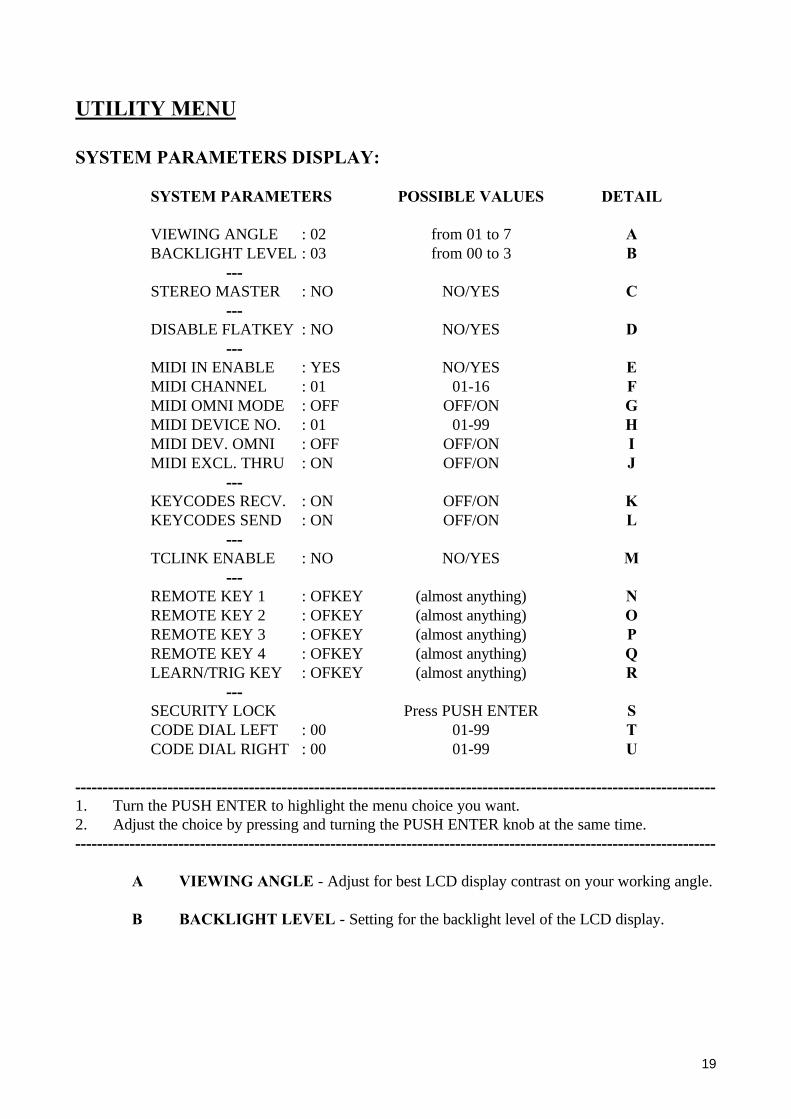
SYSTEM PARAMETERS DISPLAY:
SYSTEM PARAMETERS POSSIBLE VALUES DETAIL
VIEWING ANGLE : 02 from 01 to 7 ABACKLIGHT LEVEL : 03 from 00 to 3 B
---STEREO MASTER : NO NO/YES C
---DISABLE FLATKEY : NO NO/YES D
---MIDI IN ENABLE : YES NO/YES EMIDI CHANNEL : 01 01-16 FMIDI OMNI MODE : OFF OFF/ON GMIDI DEVICE NO. : 01 01-99 HMIDI DEV. OMNI : OFF OFF/ON IMIDI EXCL. THRU : ON OFF/ON J
---KEYCODES RECV. : ON OFF/ON KKEYCODES SEND : ON OFF/ON L
---TCLINK ENABLE : NO NO/YES M
---REMOTE KEY 1 : OFKEY (almost anything) NREMOTE KEY 2 : OFKEY (almost anything) OREMOTE KEY 3 : OFKEY (almost anything) PREMOTE KEY 4 : OFKEY (almost anything) QLEARN/TRIG KEY : OFKEY (almost anything) R
---SECURITY LOCK Press PUSH ENTER SCODE DIAL LEFT : 00 01-99 TCODE DIAL RIGHT : 00 01-99 U
----------------------------------------------------------------------------------------------------------------------1. Turn the PUSH ENTER to highlight the menu choice you want.2. Adjust the choice by pressing and turning the PUSH ENTER knob at the same time.----------------------------------------------------------------------------------------------------------------------
A VIEWING ANGLE - Adjust for best LCD display contrast on your working angle.
B BACKLIGHT LEVEL - Setting for the backlight level of the LCD display.

20
SYSTEM PARAMETERS DISPLAY:continued...
C STEREO MASTER - When setting up two TC1128 units to work in stereo, setthe unit that you will adjust to be the "master", and the other unit (a slaveTC1128/TC1128X) will follow all adjustments made by the master as a completeclone/copy. Refer to the short stereo explanation in this manual.
D DISABLE FLATKEY - Disable the FLAT key so that no one can change an EQsetting to flat accidentally during a performance.
E MIDI IN ENABLE - MIDI enable tells the TC1128 to listen to the MIDI input forremote commands coming in at the MIDI INPUT port. This must be set to YESwhen working as a slave unit.
F MIDI CHANNEL - Select one of the 16 MIDI channels for sending and receivingdata. (Read the omni definition...)
G MIDI OMNI MODE - Select omni mode if you want the unit to send data on theMIDI CH set in F and receive data from any MIDI channel.
H MIDI DEVICE NO. - MIDI device number is the same as an address. In stereomode, units need to be set to the same device number (1). Another example is aTC6032 or the EQTALK computer program system where each unit must have aunique device number (1 to 32).
I MIDI DEV. OMNI - Select device omni mode if you want the TC1128 to listen toall MIDI device numbers (Quad applications ?). This is also VERY helpful if youneed to download a MIDI SYS EXCL. DUMP but don't know the device number ofthe TC1128 that is sending (for example, previously recorded preset data).
J MIDI EXCEL. THRU - This should normally be set to ON. When a command issent from a MIDI command device such as EQTALK to a particular devicenumber, the command is sent through all units in a daisy chained system. Howeverthe command is only accepted in the unit with that exact device number. If theselection is set to OFF the command will stop in this unit and therefore never reachthe intended unit.
K KEYCODES RECV - Keycodes are the numbers that are sent out over the MIDIconnection every time a key on the front panel is pressed. If you have sent these to aMIDI recorder, activate this to "listen" to them.
L KEYCODES SEND - Transmit keycodes if you want to record front panel controlcommands into a MIDI recorder (sequencer) or other TC1128/TC1128Xs.
M TCLINK ENABLE - Select TCLINK enable if you want to use the TC0144SERIAL REMOTE CONTROLLER. This a remote control designed specially forlive use for direct access to any preset number.

21
SYSTEM PARAMETERS DISPLAY:continued...
N-R REMOTE KEYS 1-5 - The ASSIGN SWITCH connector on the back panel is asimple two wire connection that can activate 5 functions. All 5 are fullyprogrammable and can be set here. The REMOTE function can be performed by theTC0050 remote controller, or you can make your own box with 5 momentaryswitches (plus a few resistors) to press following button or do one of the followingfunctions:
GAIN EQ ON FREEZEDISPLAY FLAT TRACKSWEEP SINGLE BAND BROAD BANDLOW SHELVING HIGH SHELVING RECALLADD STORE UTILITYFILTER ENTER EQ (always) onEQ (always) off FREEZE (always) on FREEZE (always) offDISPLAY 1 DISP. 2 EQ/SA DISP. 3 (EQ)DISPLAY 4 (SA) TRACK (always) on TRACK (always) offSWEEP (always) on SWEEP (always) off PRESET DOWNPRESET UP OFF KEY (default) PRESET 1PRESET 2 PRESET 3 PRESET 4
S-U SECURITY LOCK - First select your security lock code number for dialing left with T. Thenselect your security lock code number for dialing right with U. To activate the SECURITYLOCK select S and press PUSH ENTER. To open the security lock you have to dial thenumbers you have set in T and U. It is like a safe box. Feel the clicks on the PUSH ENTERknob, and first dial the chosen number to the left, and then the chosen number to the right.
WARNING: IF YOU FORGET YOUR COMBINATION, YOU MUST PERFORM AMINOR RESET. (Hold the PUSH ENTER knob pushed in for 10 seconds at startup.)Remember that security lock values and memory protect is reset/canceled !

22
TRACK PROGRAM DISPLAY:
TRACK FUNCTIONS POSSIBLE VALUES DETAIL
SEARCH & DESTROY: ON --/ON ASEARCH MAX BAND: -- --/ON BMAKE ACTUAL RESP: -- --/ON CSHOW ACTUAL RESP: -- --/ON DALIGN SA RESP : -- --/ON EAUTOLIN APPEND : -- --/ON FSINGLE RUN AUTOL: -- --/ON GREC/PLAY CUELIST: -- --/ON HMIDI ENABLE : -- --/ON IPOST EDIT : -- --/ON J---LED = MIDI IN : ON --/ON KLED = TIME LOCK : ON --/ON L
A SEARCH & DESTROY - Select ON if you want to make an automatic search anddestroy of feedback. In the ON position the function will be activated by pressingthe TRACK key on the frontpanel. The analyzer will now find out where thefeedback is, and the eq will take down the feedback band by a predefined number ofdB's (destroy ratio). Set the destroy ratio in the EQUALIZER menu. An example:set the destroy ratio at -3dB. Press TRACK. The eq will now cut the band where thefeedback is by 3 dB from where it was set. If you still have feedback, either in thesame band or in another band then press TRACK once - again the current highestenergy band is cut by 3 dB.
B SEARCH MAX BAND - Select ON if you only want to find the feedback withoutsuppressing it. When pressing the TRACK key, the cursor on the eq will move tothe current feedback band. You can then decide if you want to suppress it. To takeaway the feedback in this mode you press PUSH ENTER and turn up/down theband as you normally do when in FILTER mode.
C MAKE ACTUAL RESPONSE - If this is ON, the TC1128 will automaticallycompensate for inter-band reaction and make the audio response equal the fadercurve. Draw on the display your desired curve. Press TRACK button and theTC1128 will set the filters to obtain your desired curve. The display will at the sametime show this eq setting as well.
D SHOW ACTUAL RESPONSE - The automatic frequency band compensation willbe shown on the display momentarily while pressing TRACK. This will reveal theboost and cut settings required to get the expected frequency response. What yousee is the curve needed to obtain the audio response setting done by the normalfader method.

23
E ALIGN SA RESP - Activating this will create an EQ boost/cut setting thatcompensates for the frequency response spectrum stored in the FREEZE buffermemory. For correct compensation remember to set the spectrum analyzer to readthe input signal. This is done in the UTILITY menu - ANALYZER SETUP.
F AUTOLIN APPEND - This is used with the PINK NOISE OPTION so that youcan press the TRACK key and start the first measurement. Press this again to get thesecond measure-ment. This can be done for all 4 measurements. It's simply an easyway to START AUTOLIN 1-4 in the PINK NOISE menu. This way you can quickdo your 4 measurements placing the test microphone on different locations andafterwards set the weighting factors and FINAL RESPONS. NOTE: This functiondoes not use TARGET RESPONSE or FINAL RESPONSE. You can always setthese parameters after the 4 measurements in order to calculate a FINALRESPONSE. It will not affect the actual 4 measurements.
G SINGLE RUN AUTOL - If you often use the pink noise option in the sameenvironment or under the same terms you might want a quick way to make 1measurement with an automatic FINAL RESPONSE - without setting all thevarious parameters in the PINK NOISE menu again and again. Set these parameters- if needed - once and for all in the PINK NOISE MENU: SWEEP/PARAL,TARGET RESP PRE, MICAMP LEVEL or MIC AUTOSET ON (recommended),MIC RESP PRESET and NOISE LEVEL. Now simply press TRACK -programmed to SINGLE RUN AUTOL and 1 measurement with automatic FINALRESPONSE will take place. All the above parameters will have influence on theresult. The TC1128 will - when the TRACK button is pressed force the EQ ON andthe RESULT 1 WEIGHT to 10.
Refer to the PINK NOISE OPTION DISPLAY and the PINK NOISE measurementexamples for more information.
H REC/PLAY CUELIST - When ON, this programs the TRACK key to toggle therecord/playback on/off of the cuelist so you can do this quickly from the front panelinstead of entering the SMPTE option LCD menu every time.
I MIDI ENABLE - Select ON to assign the TRACK key to be MIDI input enableon/off.
J POST EDIT - Select ON to assign the TRACK key be POST EDIT mode on/off.Post edit allows you to retain the curve that you have made but you can offset itup/down or left/right. This makes moving a good frequency response "just a littlelouder" very easy to do... the frequency bands will adjust together ! Example: SelectPOST EDIT mode on this TRACK menu. Recall a preset. Press the TRACK key.Turn the PUSH ENTER wheel. Press and turn the PUSH ENTER wheel. Yourchanges is audible.
K LED = MIDI IN - In ON position the small TRACK LED will light when midisignal is received on midi input.

24
L LED = TIME LOCK - In ON position the small TRACK LED will light whenSMPTE or MTC signal is received and understood by the computer inside the TC1128.
--------------------------------------------------------------------------------------------------------------NOTE: The TRACK button can not activate the settings of K and L.
--------------------------------------------------------------------------------------------------------------

25
PRESET HANDLING DISPLAY:
PRESET HANDLING POSSIBLE VALUES DETAIL
MAKE LEGEND ALPHABET / NUMBERS A ---
INCLUDE IN-GAIN : NO NO/YES B ---
MEMORY PROTECT : NO NO/YES CMEM PROTECT LO : 01 01-99 DMEM PROTECT HI : 99 01-99 E
---MIDI EXCL DUMP FDUMP SLOW DOWN : 04 04-99 G
----------------------------------------------------------------------------------------------------------------------Turn the PUSH ENTER key to the number you want. Adjust by pressing and turning the PUSHENTER key at the same time.----------------------------------------------------------------------------------------------------------------------
A MAKE LEGEND - This screen appears enabling you to edit any preset name.Move the cursor to any letter by turning the PUSH ENTER . Press the PUSHENTER to choose the correct letter or number. Name other presets while you're inthis menu by moving the cursor to the "P" in the end. Press and turn PUSH ENTERto select the preset number on top of the display.
B INCLUDE IN-GAIN - This selects whether the setting of the input gain should bestored and recalled as a part of a preset. Sometimes you may want to turn this off sothat "live" input gain volumes are not overwritten upon recall.
C MEMORY PROTECT - Select ON if you want memory protection on yourpresets. In D and E you adjust two numbers. All presets between and including thesenumbers will be protected from storing new eq settings. WARNING: A MINORRESET WILL RETURN THIS TO THE DEFAULT OF NO PROTECTION !
D MEM PROTECT LO - Select the number where the memory protection starts.
E MEM PROTECT HI -Select the number where the memory protection stops.

26
F MIDI EXCL DUMP - Press PUSH ENTER . The unit will then ask for a devicenumber. This is adjusted by turning the PUSH ENTER wheel. Press PUSH ENTERto start sending the MIDI exclusive protocol out via the MIDI output port. Allpresets can be dumped to another TC1128/TC1128X. The receivingTC1128/TC1128X only has to be set with the proper device number for the dumpto be recieved properly. Remember to set the device number equal to thereceiving unit or set the recieving unit to MIDI DEV. OMNI ON. The presetdata that is sent is: Eq band settings, input/output gain settings, legend, and 6/12 dBrange setting.
G DUMP SLOW DOWN - Press PUSH ENTER .The transmission of MIDI data cansometimes cause problems with the receiving device, so a simple method of slowingthis transmission rate has been included. Adjust this if you are experiencingdownload problems and suspect speed problems.

27
ANALYZER SET-UP DISPLAY:
SPECTRUM ANALYZER POSSIBLE VALUES DETAIL
SA SOURCE : OUT IN/OUT ASA LEVEL : 0 dB -12dB to +6dB BSA AUTO LEVEL: OFF OFF/ON CSA READ MODE: PEAK AVG./PEAK DSA RESP.TIME: MED SLOW/MED./FAST E
A SA SOURCE - The spectrum analyzer can be set to indicate the frequency contentof the signal either before or after the EQ circuit. IN = pre-EQ and OUT = post-EQ.When indicating the input signal, you can FREEZE the response curve andautomatically generate an inverse EQ curve to create a flat response. Read thedescription of the ALIGN SA RESP selection on the TRACK DISPLAY.
B SA LEVEL - Changes the sensitivity (input gain) of the spectrum analyzer. Undermanual control you should desire an absolute indication of volumes in the frequencybands.
C SA AUTO LEVEL - Automatic adjustment of spectrum analyzer input gain so thatthe spectrum is always visible but volumes are relative not absolute.
D SA READ MODE - Spectrum analyzer audio averaging. Average gives an overallview of the signals frequency content and Peak is for viewing transients. For mostapplications we recommend average analysis.
E SA RESP. TIME - Spectrum analyzer display speed. If you are only interested in arough idea of the frequency spectrum choose a slow response. If you are watchingfor the frequency spectrum of transients (drums) set this to FAST.

28
EQUALIZER SET-UP DISPLAY:
EQUALIZER POSSIBLE VALUES DETAIL
EQ RANGE : 12dB 12dB/6dB ASOFT CROSSFADE: NO NO/YES BSILENT UPDATE : NO NO/YES CLOWCUT FILTER: OFF OFF/15Hz/30Hz/45Hz DHIGHCUT FILTER: OFF OFF/15KHz EBR-BAND SLOPE: 9 dB 12/9/6/3 dB FDESTROY RATIO: -6 dB -12dB to +12dB G
A EQ RANGE - To set 6 or 12 dB eq boost/cut range. In the 6dB range theresolution increases to 1/2 dB steps. The range setting is stored in presets.
B SOFT CROSSFADE - The boost/cut values on all frequency bands areincremented from the current preset settings to the next preset settings. The furtherthese values are from each other, the longer the crossfade will take. Average cross-fades are 3 to 4 seconds.
C SILENT UPDATE - If this feature is ON, the TC1128 will automatically turn theSOFT CROSSFADE function ON or OFF depending on the low frequency contentat the time a preset is recalled. If there is high input on frequencies lower than 400Hz, SOFT CROSSFADE will be OFF.
D LOWCUT FILTER - This is a completely independent computer controlled analogfilter that can get rid of rumble or other low frequency noise without having to useyour low graphic filter bands. These are 12dB/oct. Butterworth type lowcut filterswith -3 dB points of 15 Hz or 30 Hz or 45 Hz.
E HIGHCUT FILTER - This is also a separate computer controlled analog filter foreliminating high frequency content. This is a 6dB/oct. filter with a - 3dB point of 15KHz.
F BR-BAND SLOPE - This allows different "Q" factors when adjusting the equalizerin BROAD mode. The different settings define how the adjacent bands will beeffected when boosting or cutting frequencies. This can be accessed easily when inthe normal editing mode (FILTER) by just holding down the BROAD button whileturning the PUSH ENTER knob.
G DESTROY RATIO - The destroy ratio is the number of dB the highest energyband is to be reduced when the SEARCH & DESTROY function is activated. TheTRACK button can be programmed to activate the SEARCH & DESTROYfunction. Notice that the DESTROY RATIO can also be a positive number, actuallyboosting a frequency band. This can be used by a guitar player to emphasize aspecific frequency while playing (induced feedback ?) or for calibrating a desiredfrequency response curve by playing a harmonic and hitting track. Some musicianshave reported "developing" their desired EQ curve by activating SEARCH ANDDESTROY multiple times (on their foot switch) in response to them playing certainnotes or harmonics on their instrument !

29
PINK NOISE OPTION DISPLAY:
PINK NOISE MENU POSSIBLE VALUES DETAIL
START AUTOLIN 1 PUSH ENTER ASTART AUTOLIN 2 PUSH ENTER BSTART AUTOLIN 3 PUSH ENTER CSTART AUTOLIN 4 PUSH ENTER DFINAL RESPONSE PUSH ENTER E---VIEW RESPONSE PUSH ENTER + TURN = MORE F---MEASUREMENT NO : 00 OFF(00) or 01- 04 GRESULT 1 WEIGHT : 00 00-10 HRESULT 2 WEIGHT : 00 00-10 IRESULT 3 WEIGHT : 00 00-10 JRESULT 4 WEIGHT : 00 00-10 K---AUTOLIN METHOD : SWEEP SWEEP/PARAL L---TARGET RESP PRE : 00 OFF(00) or 01-99 M---MICAMP LEVEL : 16 00(invalid) or 01-32 NMICAMP AUTOSET : ON OFF/ON OPHANTOM POWER : OFF OFF/ON PMIC RESP PRESET : 00 OFF(00) or 01-99 QNOISE LEVEL : 16 01-99 RPINK NOISE ONLY : OFF OFF/ON S
---------------------------------------------------------------------------------------------------------------------1. Turn the PUSH ENTER to the menu choice you want.2. Adjust the choice by pressing and turning the PUSH ENTER knob at the same time.---------------------------------------------------------------------------------------------------------------------
A START AUTOLIN 1 - locate the "cursor" over this and press the PUSH ENTERknob to start the first measurement. A basic measurement can be done with just thisONE MEASUREMENT... the 2,3,4 autolin is used for more "involved" acousticanalysis.
B START AUTOLIN 2 - second measurement
C START AUTOLIN 3 - third measurement
D START AUTOLIN 4 - fourth measurement
E FINAL RESPONSE - result of multiple measurements including weighting factors.If less than 4 measurements are taken, the weighting factors for the ones not usedMUST BE SET TO 00 !

30
F VIEW RESPONSE - this is selected to show the contents of the 4 AUTOLINmemories. When selected, you can turn the PUSH ENTER knob and scroll view theresponse curves in the 4 memories. NOTE: the first few seconds of viewing showsthe actual resultant frequency response, and then the view changes to the boost/cutsettings required to obtain the resultant frequency response.
G MEASUREMENT NO. - A counter that shows how many AUTOLINmeasurement buffers contain measurement data. This helps remind you how far youare with (for example) a 4 measurement FINAL RESULT analysis.
H RESULT 1 WEIGHT - Weighting factors are used to tell the FINAL RESPONSEcalculation exactly where the test microphone is located in an acoustic space. Tocreate a proper FINAL RESPONSE one normally sets a microphone in the middleof the seating area and set the RESULT 1 WEIGHT to a fairly high number (7 to10). A second measurement would be done by placing the same microphone off tothe one side of the seating area and perform a second measurement (STARTAUTOLIN 2) and set the RESULT 2 WEIGHT to a relatively low number becausethe OFF-AXIS response should be less important to the final result.
YOUR TALENT AND EXPERIENCE DETERMINES THE MICROPHONEPOSITION AND IMPORTANCE (WEIGHTING) IN THE FINAL RESULTMEASUREMENT !!
I RESULT 2 WEIGHT - This tells the importance of this particular measurementrelative to the FINAL RESPONSE curve.
J RESULT 3 WEIGHT - How important is this microphone location to the FINALRESPONSE ?
K RESULT 4 WEIGHT - How important is this microphone location ?
WEIGHTING EXAMPLE: The 00-10 range for each weighting factor allows finecontrol of percentages of importance to the FINAL RESPONSE. You can arrive ata percentage figure by taking the weight number and dividing it by the total of allweight numbers. Here are some examples:
weighting set 1 weighting set 2 weighting set 3-------------------- --------------------- --------------------1 = 06 = 60 % 1 = 10 = 33.3 % 1 = 08 = 72.7 %2 = 02 = 20 % 2 = 10 = 33.3 % 2 = 02 = 18.1 %3 = 01 = 10 % 3 = 05 = 16.6 % 3 = 01 = 9 %4 = 01 = 10 % 4 = 05 = 16.6 % 4 = 00 = 0 %
31
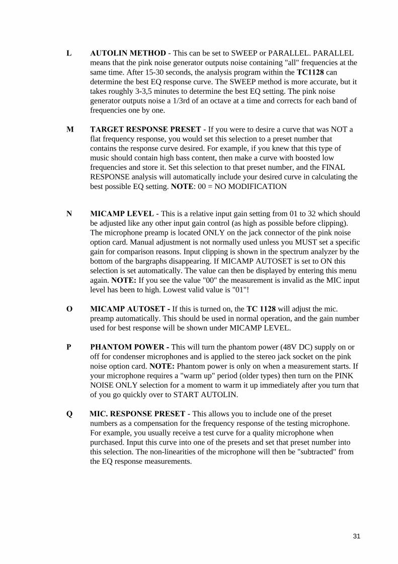
L AUTOLIN METHOD - This can be set to SWEEP or PARALLEL. PARALLELmeans that the pink noise generator outputs noise containing "all" frequencies at thesame time. After 15-30 seconds, the analysis program within the TC1128 candetermine the best EQ response curve. The SWEEP method is more accurate, but ittakes roughly 3-3,5 minutes to determine the best EQ setting. The pink noisegenerator outputs noise a 1/3rd of an octave at a time and corrects for each band offrequencies one by one.
M TARGET RESPONSE PRESET - If you were to desire a curve that was NOT aflat frequency response, you would set this selection to a preset number thatcontains the response curve desired. For example, if you knew that this type ofmusic should contain high bass content, then make a curve with boosted lowfrequencies and store it. Set this selection to that preset number, and the FINALRESPONSE analysis will automatically include your desired curve in calculating thebest possible EQ setting. NOTE: 00 = NO MODIFICATION
N MICAMP LEVEL - This is a relative input gain setting from 01 to 32 which shouldbe adjusted like any other input gain control (as high as possible before clipping).The microphone preamp is located ONLY on the jack connector of the pink noiseoption card. Manual adjustment is not normally used unless you MUST set a specificgain for comparison reasons. Input clipping is shown in the spectrum analyzer by thebottom of the bargraphs disappearing. If MICAMP AUTOSET is set to ON thisselection is set automatically. The value can then be displayed by entering this menuagain. NOTE: If you see the value "00" the measurement is invalid as the MIC inputlevel has been to high. Lowest valid value is "01"!
O MICAMP AUTOSET - If this is turned on, the TC 1128 will adjust the mic.preamp automatically. This should be used in normal operation, and the gain numberused for best response will be shown under MICAMP LEVEL.
P PHANTOM POWER - This will turn the phantom power (48V DC) supply on oroff for condenser microphones and is applied to the stereo jack socket on the pinknoise option card. NOTE: Phantom power is only on when a measurement starts. Ifyour microphone requires a "warm up" period (older types) then turn on the PINKNOISE ONLY selection for a moment to warm it up immediately after you turn thatof you go quickly over to START AUTOLIN.
Q MIC. RESPONSE PRESET - This allows you to include one of the presetnumbers as a compensation for the frequency response of the testing microphone.For example, you usually receive a test curve for a quality microphone whenpurchased. Input this curve into one of the presets and set that preset number intothis selection. The non-linearities of the microphone will then be "subtracted" fromthe EQ response measurements.

32
R NOISE LEVEL - This is a relative adjustment for outputting a proper pink noiselevel to a power amplifier. Standard system noise will interfere with measuring sotreat the pink noise source like any other "clean" signal. Adjust for maximum signalwithout clipping in the next device in the system.
S PINK NOISE ONLY - This will turn the pink noise generator on or off withouttaking a measurement. Use this manual control for setting the NOISE LEVEL,adjusting the MICAMP LEVEL for maximum input before clipping (see N above)or verifying your system cabling. It is also used for warming older microphones upbefore measurement.

33
SMPTE / MTC OPTION DISPLAY:
SMPTE/MTC POSSIBLE VALUES DETAIL
PLAY CUE LIST: OFF OFF/ON ARECORD CUE LIST: OFF OFF/ON BEDIT CUE LIST Press PUSH ENTER CDUMP CUE LIST Press PUSH ENTER DCLEAR CUE LIST Press PUSH ENTER E---GENERATE SMPTE Press PUSH ENTER FSMPTE GEN HOURS: 00 00-23 GSMPTE GEN MIN: 00 00-59 HSMPTE GEN SEC : 00 00-59 ISMPTE GEN FRAM: 00 00-frame-rate J---TIMECODE SOURC: SMPTE SMPTE/MTC KTIMECODE OFFSET: 00 00-24 LSMPTE RATE : 24 24/25/30/30DF M
A PLAY CUE LIST - Select ON to enable the unit to read SMPTE code. This is thePlay mode, just play the SMPTE code into the unit and it will automatically switchprograms as they were recorded. This function can also be programmed to be turnedon/off by the TRACK key on the front panel if you need to do this often. The cuelist can be played and recorded at the same time for easy insertion of cue additions.
B RECORD CUE LIST - Select on to enable the unit to record the SMPTE timewhere a preset recall should take place. Normally you would connect an externalsource (tape or a SMPTE generator) so that the TC1128 will change according to aprerecorded video or multitrack music recording. You can record according to theinternal SMPTE generator signal by just starting the GENERATE SMPTEcommand (see below) and just changing presets. They will be recordedautomatically. The record function can also be programmed to be turned on/off bythe TRACK button on the front panel if desired. The cue list can be played andrecorded at the same time for easy insertion of cue additions.
C EDIT CUE LIST - The following line is shown at the bottom of the display when inCue List edit mode and you press the PUSH ENTER knob again...
X I D 00:00:00:00 P00
34
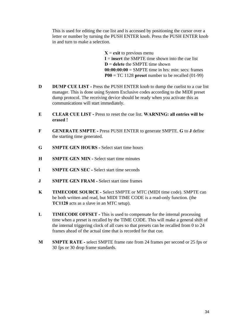
This is used for editing the cue list and is accessed by positioning the cursor over aletter or number by turning the PUSH ENTER knob. Press the PUSH ENTER knobin and turn to make a selection.
X = exit to previous menuI = insert the SMPTE time shown into the cue listD = delete the SMPTE time shown00:00:00:00 = SMPTE time in hrs: min: secs: framesP00 = TC 1128 preset number to be recalled (01-99)
D DUMP CUE LIST - Press the PUSH ENTER knob to dump the cuelist to a cue listmanager. This is done using System Exclusive codes according to the MIDI presetdump protocol. The receiving device should be ready when you activate this ascommunications will start immediately.
E CLEAR CUE LIST - Press to reset the cue list. WARNING: all entries will beerased !
F GENERATE SMPTE - Press PUSH ENTER to generate SMPTE. G to J definethe starting time generated.
G SMPTE GEN HOURS - Select start time hours
H SMPTE GEN MIN - Select start time minutes
I SMPTE GEN SEC - Select start time seconds
J SMPTE GEN FRAM - Select start time frames
K TIMECODE SOURCE - Select SMPTE or MTC (MIDI time code). SMPTE canbe both written and read, but MIDI TIME CODE is a read-only function. (theTC1128 acts as a slave in an MTC setup).
L TIMECODE OFFSET - This is used to compensate for the internal processingtime when a preset is recalled by the TIME CODE. This will make a general shift ofthe internal triggering clock of all cues so that presets can be recalled from 0 to 24frames ahead of the actual time that is recorded for that cue.
M SMPTE RATE - select SMPTE frame rate from 24 frames per second or 25 fps or30 fps or 30 drop frame standards.

35
BASIC PRINCIPLES: COMPUTER CONTROLLED EQ
Equalizers (graphic or parametric) have been one of the sound industry's main toolsfor many years. Because equalization by nature is very much an analog process it isnot surprising that it is only through the last few years that we have seen digitaltechnology in equalizers. There simply hasn't been technology around to do the jobuntil now.
The focus on graphics probably originates from the fact that they are easy to use andunderstand but - as most of us are aware of - can be a bit misleading: the responseformed by the faders can often be far from the true response. Frequency bandinteraction is a natural phenomena in a standard analog equalizer that can becompensated for in a digital implementation. Another characteristic of the analog eqis the inability to change settings quickly or to remember settings for use later.These speed and reset-ability problems have become more of a problem within thepast 5 years as the number of sound inputs approaches an AVERAGE of 40channels ! Computer controlled EQ's solve these problems, as well as offering signalanalysis and user interface improvements.
The TC1128 is a computer controlled analog EQ which offers the best of the analogadvantages together with the best of the digital control advantages. Like othercomputer controlled audio devices, the TC1128 has a computer display (LCDgraphic) for viewing and editing settings, and the ability to record and recall eq"snapshots". But there are some functions contained in the TC1128 that takeadvantage of computer control in a way that improves on the "state of the art" inuser friendliness and flexibility.
You are able to control the frequency response as a graphic equalizer (one freq.band at a time) or as a parametric eq (by setting the Q factor and SWEEPING thecenter frequency). A spectrum analyzer is contained inside to show the response ofthe incoming signal or the response of the equalized signal so that the user has theability to see exactly what he is compensating for. Refer to "THE ADVANTAGEOF EQ AND SPECTRUM ANALYSIS" for more information.
Computer compensation for boost/cut of frequencies outside of the desiredadjustment band allows precise control of just the frequency range desired. TheTC1128 does this automatically and displays the eq settings as either the traditional"fader" display or the "compensated" display. For example, by increasing the display"faders" 800 Hz, 1000 Hz and 1250 Hz to +6dB thus creating an octave filtercentered around 1000 Hz (at least that is what we think we are doing), pressing the"TRACK" button now reveals the actual response of the filter: a broad bell shapepeaking +9 dB at the indicated 1000 Hz setting. This is the deception of analoggraphic EQ's: the settings of the faders are NOT equal to the actual response,especially not with an extreme setting like this one.
36
BASIC PRINCIPLES: COMPUTER CONTROLLED EQ
continued...
By pressing the selection "MAKE ACTUAL RESPONSE", the control computerwill change the response to a close approximation of an octave filter. The displaynow shows a strange fader setting as a result of the changed response whose audioresult matches the expected boost and cut settings. Or more importantly, you cansee the actual audio response curve that results from the combination of filterinteraction.
Another exciting application of computer controlled eq's is their ability to becontrolled externally. The entire audio industry is headed towards central controlof all functions. While the inclusion of MIDI control is pretty much required on sucha product, the TC1128 has some features that really take advantage of the flexibilitythat remote control offers. A SMPTE code option allows eq programs to berecorded and recalled locked to time code for use in film or video post production.The resultant cue list has all of the features one would expect with settings of codetypes (24, 25, 30, 30DF), editing of times, offsetting, dumping, etc. TC has softwareprograms for the IBM PC (PC99) or the Apple Macintosh (MAC99) which offer allfeatures in an easy to view and modify version when a customer has many eq's thatneed to be controlled. These programs allow full file handling so settings can bestored to disk for later reference in studio, post production or theater applications.
The successful application of computer technology in the audio industry is highlydependent on the user interface. Since the advantages of computer equalization hascaught the eye (ear?) of the professional PA companies, the desire to implementthese has been growing the past couple of years. A cooperation between TCelectronics and Clair Bros. (USA) resulted in 1990 the TC6032 REMOTECONTROL. This unit uses motor faders to represent the frequency band settings inthe TC1128. By using a computer controlled fader, the technology has made theperfect combination of the traditional analog method and the computer advantages.Up to 32 audio channels can be controlled in a central location; simply select the eqchannel number, and the faders will move to the correct setting! Touch sensors arein the fader knobs so the motor torque is released when you make an adjustment.Powerful "PILE" and "ALL" modes allow multiple channels of eq to be changed atone time for situations where stage left or right should be adjusted together. Afrequency curve can be input and the remote will place the faders to make the eqfilters match this curve. In other words, this remote eq controller allows theadvantages of the computer with the great advantage of being a normal"understandable" user interface.

37
BASIC PRINCIPLES: EQ + SPECTRUM ANALYSIS
By including spectrum analysis within the TC1128, there are several powerfulfeatures that are able to be offered:
- viewing of the input signal’s frequency spectrum- viewing the result of the EQ changes (audio output)- frequency dependant preset crossfade smoothing- offering “automatic” feedback suppression- optionel automatic room acoustics compensation with maximum
matching of analysis and correction
The viewing of the input and the output frequency response is a feature that almostall musicians desire but few products provide. The audio response can be seen onthe LCD display (or optional monitor) together with the boost/cut faders so you cansee the results of your adjustments at all times !
The "SILENT UPDATE" feature found in the EQUALIZER SETUP menu uses thespectrum analyzer to decide if a preset change can be done by incremental steps ormust be changed directly to the target value. This minimizes the stepping actionbeing heard if there is a lot of bass energy below 400 Hz.
The "automatic" feedback suppression feature is called "SEARCH & DESTROY".When this feature is activated, the TC1128 is able to find the frequency band wherethe audio volume is maximum (characteristic of a feedback tone) and reduce thevolume according to a predetermined amount. This function is activated by pressingthe TRACK button on the front panel or activating one of the remote keys set to"TRACK". This function can be a life saver for non-technical people in permanentinstallations where you can mount a "PANIC" button and tell the user to hit thebutton if he hears a feedback tone !
Spectrum analysis together with a pink noise source and a microphone input allowinteractive adjustment of the EQ response curves. The PINK NOISE OPTIONoffers all of the hardware and software to perform complex room analysis. Byadding a small circuit board, you can start an automatic analysis of the roomresponse and the eq will adjust its settings for a linear response curve. You may alsoput in a preferred curve and have this included in up to 4 different "room samples"that are used to calculate the required inverse EQ settings. All of the professionalrequirements such as phantom power, mic. gain, mic. calibration, pink noise volumeand weighting of samples are included.
By having the analyzer section use the exact same 2nd order filters as the equalizer,they are perfectly matched. As a practical work tool, the combination of EQ andanalyzer in the same piece of equipment is equivalent to much more expensive testequipment because you have no use for better than 1/3rd octave analysis when usinga 1/3rd octave equalizer for correction.
Refer to the "UTILITY MENU: PINK NOISE OPTION DISPLAY" and the"AUTOMATIC ROOM ANALYSIS" for more information.
38
BASIC PRINCIPLES: EQ SYNCHRONIZED TO SMPTE/MTC
All SMPTE time code standards (24, 25, 30 and 30 drop frame) are able to bewritten or read by the TC1128 when equipped with the SMPTE OPTION. By justconnecting a cable with the synchronizing signal from your multitrack tape machine(or other SMPTE master), you can "record" and "play-back" equalizer programchanges and these will be perfectly matched to your audio (or visual) cues.
The graphic LCD display or optional monitor display allow full cue list features suchas preset labeling, manual editing, real time entry, time offsets, and down-loading ofdata to other cue list managers.
MIDI TIME CODE (MTC) can also be used as a synchronizing signal. This MIDIstandard offers the same function as SMPTE for MIDI devices (with lower timingaccuracy specs) and is supported by the TC1128 for integration into sequencerbased studio systems. A master timing source is connected to the MIDI inputconnector on the TC1128 and the MTC protocol will be read and used for recordingand playing back preset EQ changes (RECALL).
NOTE: The TC1128 does not write MTC, this is a read-only function.
Refer to the "UTILITY MENU: SMPTE/MTC OPTION DISPLAY" for moreinformation.

39
BASIC PRINCIPLES: REAL TIME MIDI CONTROL
One of the REAL exciting possibilities with the TC1128 is the ability to performdynamic equalization changes synchronized to time code ! The TC1128 is used asa slave device for a MIDI sequencer program and is controlled by a common featureof modern sequencers called a "MIDI MANAGER" page. Several major sequencerproducts contain a function which allows the user the ability to "draw" volumefaders on the screen and define the MIDI data that they transmit when moved. Avery simple MIDI protocol definition is used so a set of 30 faders can be drawn (28bands + output gain + output volume) giving a normal graphic equalizer "look" tothis control page. All normal sequencer functions such as recording, play-back andsynchronizing will now apply to the settings of the TC1128 EQ !
The ability to record and play-back dynamic EQ movements into a mix offerscreative options that have never been available before ! The frequency response ofan actor´s voice can be fluidly changing depending on his position to the camera ! Aparticular instrument can be "lifted" in the mix at just the right point, or a 2 secondguitar lick given just the right emphasis !
There are several MIDI assignable fader devices which can offer a form of controlfor remote EQ adjustment - should a limited number of boost/cut bands be ofinterest e.g. for cleaning up a film sound-track.
Another interesting feature with the MIDI protocol implementation is the inclusionof an output gain AND "output volume". The output volume command allows avolume adjust in series with the output gain so an attenuation range from + 12 dB to- 40 dB can be obtained. While the lower range is not acceptable for muting, thisrange will satisfy MANY standard mix adjustment needs ! An automated EQ +volume on your effects send/return has never been easier !

40
BASIC PRINCIPLES: STEREO LINKING OF 1128´S
Two TC1128´s can be easily connected together to exactly match the EQadjustments while using only one front panel. One of the units is set as MASTERand the other is set as SLAVE, and their MIDI in/out connections are connectedtogether. This setup allows any parameter changed on the MASTER to betransmitted to the SLAVE.
The flexibility of this configuration is especially interesting for situations where youuse a stereo configuration sometime, and mono or multiple EQ configurations othertimes (PA rental ?). Permanent installations will be interested in the MONITOROPTION for large screen viewing or using the less expensive TC1128X version asthe SLAVE equalizer.
Easy menu selections allow down-loading all preset memories from the master to theslave OR the MASTER and SLAVE can retain their own battery backed up presetinformation while still functioning in a stereo set-up.
To show how easy the stereo setup is, here is a full description of the procedure forconnecting two TC1128´s:
1. Connect the MIDI IN unit 1 to MIDI OUT unit 2, and MIDI OUT unit 1 to MIDIIN unit 2.
2. On the master unit, enter the UTILITY menu - SYSTEM PARAMETERS and set STEREO MASTER = YES, MIDI device no. = 1, and keycodes send = off.
3. On the slave, enter the UTILITY menu - SYSTEM PARAMETERS and set STEREO MASTER = NO, MIDI device no. = 1, and keycodes send = off.
The slave unit will now in sync follow all adjustments made to the master !
Refer to the "SYSTEM PARAMETERS DISPLAY" detail in this manual.
41
TECHNICAL DATA
MONITOR OPTION:
The monitor option is a PC board which can be installed in the TC1128 allowing thedata from the front panel LCD display to be viewed on an RGB or video monitor. Awide variety of monitors can be used and the card offers a choice of backgroundcolors to allow you to match your studios colors!
PAL / NTSC
There is a DIP switch on the PCB called SW1 which can set the video standardneeded. Set to OFF = PAL version (50 Hz sync), and ON = NTSC version (60 Hzsync).
COLOR
13 different colors are available for the background. This selection is made by theblack jumpers located just behind the sub-D connector.
TP 2 + 6 = light yellowTP 3 + 7 = light purpleTP 4 + 8 = light blueTP 1 + 5 and TP 2 + 6 = light brownTP 1 + 5 and TP 3 + 7 = purpleTP 1 + 5 and TP 4 + 8 = blue greenTP 2 + 6 and TP 3 + 7 = light redTP 2 + 6 and TP 4 + 8 = light greenTP 3 + 7 and TP 4 + 8 = blueTP 1 + 5 and TP 2 + 6 and TP 3 + 7 = dark redTP 1+ 5 and TP 2 + 6 and TP 4 + 8 = greenTP 1 + 5 and TP 2 + 6 and TP 4 + 8 = dark blueTP 2 + 6 and TP 3 + 7 and TP 4 + 8 = black
Dark blue is standard from the factory.
CONNECTIONS
RGB connection is made via a 9 pin sub D connector mounted on theoption circuit board. The pin layout is as follows:
pin 1: ground pin 6: intensitypin 2: not connected pin 7: not connectedpin 3: blue ( B ) pin 8: horiz. syncpin 4: red ( R ) pin 9: vert. syncpin 5: green ( G )
VIDEO OUTPUT is via an RCA jack socket, and there is an RS 232MOUSE connection, but this has not been implemented.