precast structural design updated
TRANSCRIPT

8/21/2019 Precast Structural Design Updated
http://slidepdf.com/reader/full/precast-structural-design-updated 1/32
1. Project Description
The building is a 12-storey office block in a mix commercial development comprising carparks,
shopping malls and service apartments.
A typical floor of the building measuring 24 m x 2 m !ith " m building grids in both directions
is sho!n in #igure 4.1. The design floor-to-floor height is $.% m. &taircases, lift cores and
other building services such as toilets, A'(, )*+ risers are located at each end of the floor
!hich are to be cast in-situ.
2. Design Information
a. Codes of Practice
& %$ esign /oading for uilding
0 % The &tructural (se of 0oncrete
0$, 0hapter 3 ind /oad
b. Materials
Concrete 0$5 for topping, !alls and all other in-situ !orks
04 for precast beam
05 for precast columns and hollo! core slabs
Steel
c. Dead loads
0oncrete density 6 24
artitions, finishes and services 6 1."
rick!alls 6 $.5
d. Liveloads
7ffices, staircases, corridors 6 24
/ift lobby, A'( rooms 6 1."
Toilet 6 $.5
3. Structural System
recast construction is adopted from the second storey up!ards to take advantage of the
regular building grids and simple structural layout. The areas from grids A to 0 and from 8 to
9 are, ho!ever, cast in-situ due to drops, floor openings and !ater-tightness considerations.
eside acting as load bearing !alls, staircase !ells and lift cores also function as stabilising
cores for the superstructure. The !alls are $55 mm thick, cast in-situ and are tied monolithically
at every floor.
The precast components consist of hollo! core slabs, beams, columns and staircase flights.
a. Hollow core slabs
The design of hollo! core slabs :21 mm thick; is based on class 2 prestressed concrete
structure !ith minimum 2 hours fire rating. The hollo! core slabs are cast !ith 05 concrete.
+ach unit :1.2 m nominal !idth; is designed as simply supported !ith nominal155 mm seati
at the support.
<esultant stresses are checked at serviceability and at prestress transfer. esign of the slab
is carried out by the specialist supplier.
b. Precast beams
$ mm deep full precast beams are used in the office area. The beams, !hich are unpropped
during construction, are seated directly onto column corbels and are designed as simply
supported structures at the final stage. To limit cracking of the topping concrete at the supports,
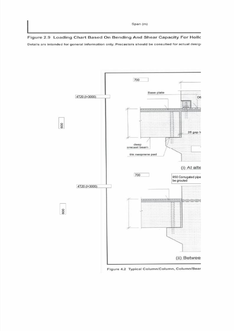
site placed reinforcement is provided as sho!n in the typical details in #igure 4.2.
c. Precast columns
fy 6 25 =>mm² mild steel reinforcement
fy 6 4%5 =>mm² high yield steel reinforcement
fy 6 4" =>mm² high yield steel reinforcement
k=>m³
k=>m²
k=>m²
k=>m²
k=>m²
k=>m²

8/21/2019 Precast Structural Design Updated
http://slidepdf.com/reader/full/precast-structural-design-updated 2/32
The columns are 55 mm x 55 mm and are cast 2-storey in height !ith base plate connection
at every alternate floor. They are designed as pin-ended at the ultimate limit state.
The base plate connection is designed !ith moment capacity to enable the columns to
behave as a 2-storey high cantilever. This is to facilitate floor installation !orks !hich are to
be carried out t!o floors in advance of a finally tied floor at any one time during the construction
of the office block. The use of base plate connection !ill eliminate heavy column props and
result in a safer and neater construction site. A nominal 5 mm gap is detailed in the design of
the column-to-column connection in order to provide sufficient tolerances for the insertion of
in-situ reinforcement at the beam support regions. The gap !ill be filled !ith
05 non-shrink grout.
+ach column is cast !ith reinforced concrete corbels in the direction of the precast beams.
The corbels are provided !ith T2 do!el bars !hich are used to prevent toppling of the
precast beams !hen the hollo! core slabs are laid. The depth of the corbel is designed to be
concealed visually !ithin the final ceiling space.
At the final state, all columns are considered braced in both directions.
d. Floor diapragm action and structural integrity
All precast components are bound by a % mm thick concrete topping !hich is reinforced !ith
a layer of steel fabric. The steel fabric serves as structural floor ties in order to satisfy the
integrity ties re?uirement under the building robustness design considerations.
The final floor structure !ill behave as a rigid diaphragm !hich transmits hori@ontal loads to
the stabilising cores at each end of the floor.
!. Design of Precast Components
a. Design of Hollow Core Slab
=et length of hollo! core slab 6 "555-55-155
6 455
6 5.5%24
6 1.%
Bmposed 6 1.
// 6 $
#rom #igure 2. of 0hapter 2, 21 mm thick hollo! core slab is ade?uate. Actual design
of prestressing reinforcement !ill be furnished by the producer of the slabs.
Support reinforcement
Although the slabs are designed as non-composite and simply supported, additional loose
/oading C / 6 Topping :% mm thick;
"555
25 5
155 155
255

8/21/2019 Precast Structural Design Updated
http://slidepdf.com/reader/full/precast-structural-design-updated 3/32
reinforcement should be placed in the topping concrete over the support in order to minimise
surface cracking and limit the crack !idths. The additional support reinforcement may be
calculated as belo! C
/oading C / :imposed; 6 1.%
// 6 $
(ltimate load 6 1.4 1. D 1.% $.5
6 .2
&upport moment 6
6
6 $2.
h 6 21D%
6 2"5
@ 6 5."h
6 224
As 6 )>:5."fy@;
6 $$.5 15E%>:5."
6 $%".1
5.5"$?l²
5.5"$ X .2 X .4²
"se #$% & 2%% c'c ()s * 3+3 mm² 'm,
8/21/2019 Precast Structural Design Updated
http://slidepdf.com/reader/full/precast-structural-design-updated 4/32
55
% 5 5
4T25 :B6$555; %
F5 0orrugated pipebe grouted
4T25 :B6$555;
% 5 5
55

8/21/2019 Precast Structural Design Updated
http://slidepdf.com/reader/full/precast-structural-design-updated 5/32
T15G255 :B62455;% mesh
% 5 5
$ 2 5
2 1
% t o
p p i n g
21 T
55>"55beam
"55
15
55 1555
T15G255 %
% 5 5
1 2
55>"55x$ deep prec
155 seating
25 455
15
8/21/2019 Precast Structural Design Updated
http://slidepdf.com/reader/full/precast-structural-design-updated 6/32
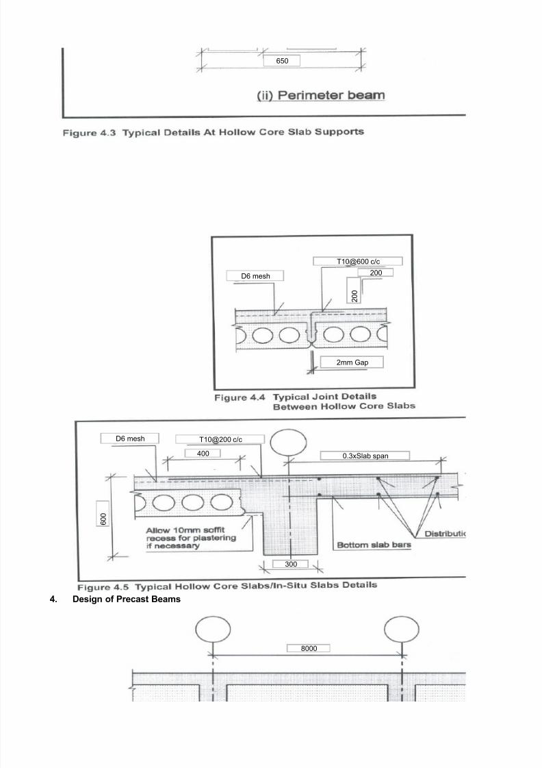
!. Design of Precast -eams
%5
T15G%55 c>c
255
2 5 5
% mesh
2mm Hap
% mesh T15G255 c>c
5.$x&lab span
% 5 5
455
$55
"555

8/21/2019 Precast Structural Design Updated
http://slidepdf.com/reader/full/precast-structural-design-updated 7/32
$. Design oadings
a. -ending Moment
? 6 / :beam s>!; 6 :5." x 5.$2 D 5.21 x 5.; x 24
'ollo! core slab :8ointed !t; 6 2."x.
Topping 6 5.5%x24x"
Bmposed 6 1.I"
Total
// 6 $.5x"
Design ultimate load 6 1.4x%."D1.%x24
2. imit State Design
6 11".5$x.$E2>"
h 6 $ mm
d 6 $- mm
b 6 55 mm
6
6 .$x15E-4
Js 6 .$x15E-4x4
As 6 4"%
)t mid&span M/ * 0l² '1
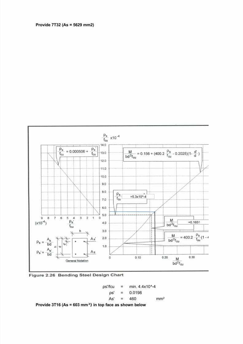
)D>:bd2fcu; "%.2 15E%>:55 4%5E2 4;
#rom #igure 2.2% in 0hapter 2, ρs>fcu
mm²
55
55x55 0 0olumn
55
"55
1515
$
$ 2 5
2 1
l6$55
8/21/2019 Precast Structural Design Updated
http://slidepdf.com/reader/full/precast-structural-design-updated 8/32
Proide #32 ()s * 452+ mm2,
JsK>fcu 6 min. 4.4x15E-4
JsK 6 5.51"
AsK 6 4%5 mm²
Proide 3#$5 ()s * 5%3 mm²) in top face as sown below
6.$x15E-4
65.1%1

8/21/2019 Precast Structural Design Updated
http://slidepdf.com/reader/full/precast-structural-design-updated 9/32
b. 6ertical Sear
Total shear 3 6 11".5$ x .$>2
6 4$5." k=
v 6 4$5." x15E$> :55x4%5;
6 1."$
)inimum steel to be provided at the beam end to prevent bond slip failure isC
As 6 3>5."fy 6 4$5."x15E$>:5."x4%5;
6 111
6 5.4L
#rom #igure 2.2, in 0hapter 2, vc 6 5.
'ence Asvfsv 6 :1."- 5.; 55>:5." 4%5;
6 1.
Proide #$%& 4c'c for $.! m bot ends. (%.2l,
( )sfs * 2.%+ 7 $.5%8 9:,
=>mm²
mm²
=>mm²
$T1%
4T15
T$2

8/21/2019 Precast Structural Design Updated
http://slidepdf.com/reader/full/precast-structural-design-updated 10/32
At 1.4 m from beam end, 3 6 4$5."- 11".5 x 1.4 k=
6 2%.% k=
v 6 2%.% 15E$ > :55 4%5;
6 1.1
Asv>&v 6 :1.1%- 5.; 55 B :5." 4%5;
6 5.1
Proide #$%&2%% lin;s ()s's, * %.1 7 %.$, for te remaining middle span.
c. Interface Hori<ontal Sear
Although the topping is considered non-structural, it is prudent to check that there should be
no separation of the topping from the precast beam at the interface. At mid-span, compression
generated in the topping concrete isC
0ompression #orce 6 5.4fcu be t
6 5.4 $5 55 % 15E-$
6 4$"." k=
0ontact idth 6 55 mm
0ontact /ength 6 5.le
6 5.x$55
6 $.% m
Average interface hori@ontal shear stress,
vh 6 4$"." x 15E$>:55 x $%5;
vh 6 5.24
peak vh 6 2x5.24
6 5.4"
Hence te topping layer sould not separate at te interface.
=>mm
=>mm
=>mm²
=>mm²
=>mm²
wic is less tan %.44 ='mm² in Part $8 #able 4.48 CP54 for as&cast surface witout lin;s.

8/21/2019 Precast Structural Design Updated
http://slidepdf.com/reader/full/precast-structural-design-updated 11/32
d. Support >einforcement
Although the beams are designed as simply supported structures, it is advisable to place
additional reinforcement over the support to prevent excessive cracking !hen the beams
rotate at the support under service load. The additional steel may be calculated as follo!s C
/oading C / :imposed; 1.x" 6 14
// $x" 6 24
1.4x14D1.%x24 6 "
&upport moment 6 5.5"?lM
6 5.5" " .$M
6 24.$
h 6 %55
@ 6 5."h
As 6 )>:5."fy@;
6 24.$ 15E%>:5."
6 12"%
Proide !#2% ()s* $24 mm2 , oer te support as sown in Figure !.2.
e. Deflection
At mid-span, )D 6 "%.1
6 "%.2 15E%> :55
6 .4$
fs 6 :>";fy :As re?>As p
6 :>"; 4%5 :4"%>
6 2"5.2
#rom art 1, Table $.11, 0% the modification factor for tension reinforcement6 5. and for
compression reinforcement 6 1.5"
)inimum d 6
6 45.%mm N 4%5 mm
(ltimate loading
)D>bd²
$55 I :25 x 5. x 1.

8/21/2019 Precast Structural Design Updated
http://slidepdf.com/reader/full/precast-structural-design-updated 12/32
f. ?nd -earing
i. ?ffectie -earing @idt
ermissible ultimate bearing stress from art 1, clause .2.$.4, 0 %
6 5.4fcu
6
6 1"
To even out surface irregularities at the beam and corbel surfaces, provide 155 x 45 x " mm
thick neoprene pad at the beam support.
0ontact pressure 6 4$5." 15$>:155 4
6 .$
6 .N1"
ii. Sear Friction Steel
5.4 X 4
=>mm
=>mm
=>mm
4 -
255
12
25
' 6 % 5 5
155x45x" thk

8/21/2019 Precast Structural Design Updated
http://slidepdf.com/reader/full/precast-structural-design-updated 13/32
'ori@ontal shear friction steel is calculated as As 6 3>5."fy assuming conservatively 6 1.5
As 6 4$5." 15E$>:5."
6 15%
rovide $T1% loops at 5 c>c at the beam ends as sho!n. :As6125mmM;
Cec; minimum bar bending radius8 r
Tension force per bar 6 5." x 4%5 x 251 x 15
6 "5.44
Actual tension force per bar #bt 6 "5.4 15%>125
6 1.1
ab 6 5
F 6 1%
)inimum r 6 #btO1 D 2:F>ab;P >2fcu
6 1.x15E$O1 D2:1%>5
6 "1.%%
say r 6 %F
6 %
c. Design of Precast Column
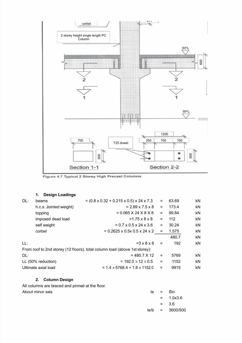
A typical 2-storey high precast column is sho!n in #igure 4. belo!C
mm²
$xT1% (-loop G 5 c>c
55
r6%F
T1% /oop
25
$ 5
% 5 5
1
%
t h k
5 thk non-shrink groutolt from lo!er 0 column
8/21/2019 Precast Structural Design Updated
http://slidepdf.com/reader/full/precast-structural-design-updated 14/32
$. Design oadings
/C beams 6 :5." x 5.$2 D 5.21 x 5.; x 24 x .$ 6 %$.% k=
h.c.s. 8ointed !eight; 6 2." x . x " 6 1$.4 k=
topping 6 5.5% 24 " " 6 ."4 k=
imposed dead load 61. x " x " 6 112 k=
self !eight 6 5. x 5. x 24 x $.% 6 $5.24 k=
corbel 6 5.2%2 x 5.x 5. x 24 x 2 6 1. k=
4"5. k=
//C 6$ x " x " 6 12 k=
/C 6 4"5. 12 6 % k=
// :5L reduction; 6 112 k=
(ltimate axial load 6 1 k=
2. Column Design
All columns are braced and pinned at the floor.
About minor axis Be 6
6 1.5x$.%
6 $.%
le>b 6 $%55>55
#rom roof to 2nd storey :12 floors;, total column load :above 1st storey;C
6 12.5 X 12 X 5.
6 1.4 %".4 D 1.% 112.5
ßlo
% 5 5
corbel
2 storey height single length 00olumn
55
1255
25 2555
5 5
5 5
T2 do!el
8/21/2019 Precast Structural Design Updated
http://slidepdf.com/reader/full/precast-structural-design-updated 15/32
6 .2
6 .2N1
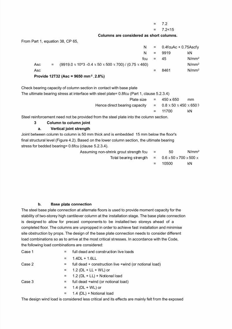
Columns are considered as sort columns.
#rom art 1, e?uation $", 0 %,
= 6 5.4fcuAc D 5.Ascfy
= 6 1 k=
fcu 6 4
Asc 6
Asc 6 "4%1
0heck bearing capacity of column section in contact !ith base plate
The ultimate bearing stress at interface !ith steel plate6 5."fcu :art 1, clause .2.$.4;
late si@e 6 45 x %5 mm
'ence direct bearing capacity 6
6 1155 k=
&teel reinforcement need not be provided from the steel plate into the column section.
3 Column to column Aoint
a. 6ertical Aoint strengt
8oint bet!een column to column is 5 mm thick and is embedded 1 mm belo! the floorKs
final structural level :#igure 4.2;. ased on the lo!er column section, the ultimate bearing
stress for bedded bearing6 5.%fcu :clause .2.$.4;.
Assuming non-shrink grout strength fcu 6 5
Total bearing strength 6
6 1555 k=
b. -ase plate connection
The steel base plate connection at alternate floors is used to provide moment capacity for the
stability of t!o-storey high cantilever column at the installation stage. The base plate connection
is designed to allo! for precast components to be installed t!o storeys ahead of a
completed floor. The columns are unpropped in order to achieve fast installation and minimise
site obstruction by props. The design of the base plate connection needs to consider different
load combinations so as to arrive at the most critical stresses. Bn accordance !ith the 0ode,
the follo!ing load combinations are consideredC
0ase 1 6 full dead and construction live loads
6 1.4/ D 1.%//
0ase 2 6 full dead D construction live D!ind :or notional load;
6 1.2 :/ D // D /; or
6 1.2 :/ D //; D =otional load
0ase $ 6 full dead D!ind :or notional load;
6 1.4 :/ D /; or 6 1.4 :/; D =otional load
The design !ind load is considered less critical and its effects are mainly felt from the exposed
=>mm²:1.5 X 15E$ -5.4 X 5 X 55 X 55; > :5. X 4%5; =>mm²
=>mm²
Proide $2#32 ()sc * +54% mm² , 2.1B,
5." X 5 X 45 X %5
=>mm²
5.% 5 55 55
8/21/2019 Precast Structural Design Updated
http://slidepdf.com/reader/full/precast-structural-design-updated 16/32
faces of the beam and column perpendicular to the !ind direction. This !ill be less than the
notional load of 1.L dead load.
The base plate connection is be checked in both the maQor and minor column axes and
taking into account the column slenderness effect.
y inspection, the most critical stresses !ill take place at the edge columns next to the in-situ
floor as there !ill be minimum axial load !ith maximum overturning moment and hence
maximum tensile forces in the bolts during the temporary stage. The transfer of floor loading
to the edge column is sho!n in #igure 4.".
A final check on the connection should be made to ensure that continuous vertical ties are
provided through the column Qoint and throughout the building height.
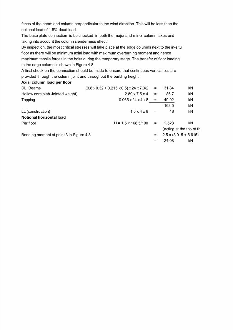
)ial column load per floor
/C eams 6 $1."4 k=
'ollo! core slab 8ointed !eight; 2." x . x 4 6 "%. k=
Topping 6 4.2 k=
1%". k=
// :construction; 1. x 4 x " 6 4" k=
=otional ori<ontal load
er floor ' 6 1. x 1%".>155 6 2.2" k=
:acting at the top of th
ending moment at point $ in #igure 4." 6 2. x :$.51 D %.%1;
6 24.5" k=
:5." 5.$2 D 5.21 5.; 24 .$>2
5.5% 24 4 "

8/21/2019 Precast Structural Design Updated
http://slidepdf.com/reader/full/precast-structural-design-updated 17/32

8/21/2019 Precast Structural Design Updated
http://slidepdf.com/reader/full/precast-structural-design-updated 18/32
mm
k=>m²
k=>m²
k=>m²

8/21/2019 Precast Structural Design Updated
http://slidepdf.com/reader/full/precast-structural-design-updated 19/32
5
k=>m>m
mm
mm
%5 224;
k=>m²
k=>m²
k=>m²
mm²>mm

8/21/2019 Precast Structural Design Updated
http://slidepdf.com/reader/full/precast-structural-design-updated 20/32
)esh
2
s :4nos; to

8/21/2019 Precast Structural Design Updated
http://slidepdf.com/reader/full/precast-structural-design-updated 21/32
k '.0. &lab
$ deep precast
)esh
% t
o p p i n g
21 Thk '.0. slab
st beam

8/21/2019 Precast Structural Design Updated
http://slidepdf.com/reader/full/precast-structural-design-updated 22/32
% 5 5
%
8/21/2019 Precast Structural Design Updated
http://slidepdf.com/reader/full/precast-structural-design-updated 23/32
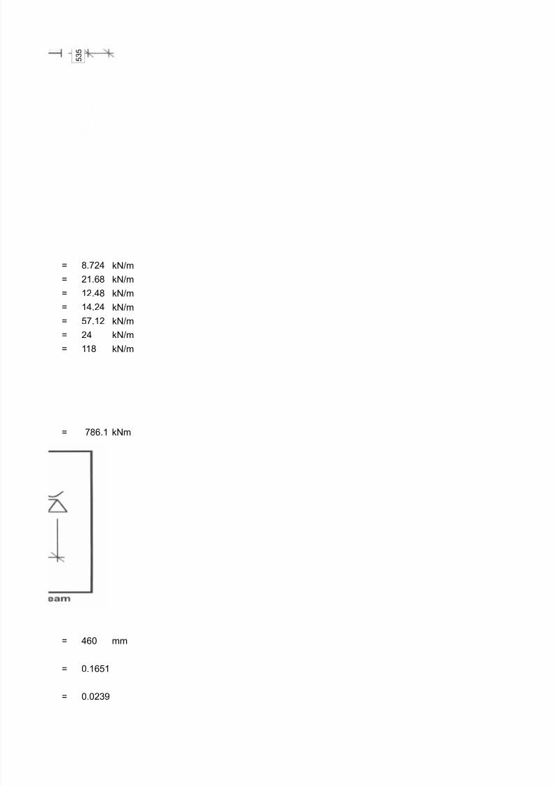
6 ".24 k=>m
6 21.%" k=>m
6 12.4" k=>m
6 14.24 k=>m
6 .12 k=>m
6 24 k=>m
6 11" k=>m
6 "%.1 k=m
6 4%5 mm
6 5.1%1
6 5.52$
$

8/21/2019 Precast Structural Design Updated
http://slidepdf.com/reader/full/precast-structural-design-updated 24/32

8/21/2019 Precast Structural Design Updated
http://slidepdf.com/reader/full/precast-structural-design-updated 25/32

8/21/2019 Precast Structural Design Updated
http://slidepdf.com/reader/full/precast-structural-design-updated 26/32

8/21/2019 Precast Structural Design Updated
http://slidepdf.com/reader/full/precast-structural-design-updated 27/32
k=>mM
k=>mM
k=>mM
k=>m>m
mm
4%5 5."x%55;
mmM>mm
k=-m
%5E2;
ov;
2;
=>mmM
79
";

8/21/2019 Precast Structural Design Updated
http://slidepdf.com/reader/full/precast-structural-design-updated 28/32
5;
79

8/21/2019 Precast Structural Design Updated
http://slidepdf.com/reader/full/precast-structural-design-updated 29/32
4%5;
-$
k=
k=
mm
mm
:+?. 5 art 1;
;P>:2x4x1%;
mm
mm
mm

8/21/2019 Precast Structural Design Updated
http://slidepdf.com/reader/full/precast-structural-design-updated 30/32
$ % 5 5
$ % 5 5
1

8/21/2019 Precast Structural Design Updated
http://slidepdf.com/reader/full/precast-structural-design-updated 31/32
˃ 1 k=
˃ 1 kN 79
15E-$
15E-$

8/21/2019 Precast Structural Design Updated
http://slidepdf.com/reader/full/precast-structural-design-updated 32/32
e corbel;