precast prestressed wall •:• system used for water ... journal...an all precast prestressed...
TRANSCRIPT

•:* Design-Construction Feature
Precast Prestressed WallSystem Used for Water•:•Storage Reservoir
Vern C. Rogne, P.Eng.Senior Project EngineerReid, Crowther & Partners Ltd.Regina, SaskatchewanCanada
Douglas L. Harrison,P.Eng.
Senior Structural EngineerReid, Crowther & Partners Ltd.
Regina, Saskatchewan
T he requirements set forth by the Cityof Regina for the North West Reser-
voir specified a desired reservoir capac-ity of approximately 10 million imperialgallons (45 1/2 million liters)" with a diam-eter not less than 220 ft (67.1 m) normore than 230 ft (70.1 m).
A further requirement was that sensi-tive attention be given to aesthetictreatment and landscaping so that thestructure would harmonize with theexisting homes and proposed freewaywhich border the project site. Designwas started in April 1978 with a target ofplacing the reservoir in service beforethe summer of 1979.
'Note: 1 U.S. gallon equals 0.827 imperial gallons
Consideration of these constraints andhydraulics established that a circularstructure, with an inside diameter of 225ft (68.6 m) and a wall height of about 38
ft (11.6 m), would most efficiently satisfythe project requirements.
Since 38 ft (11.6 m) appeared to bethe upper practical limit of wall height,the reservoir floor was sloped down tothe center to satisfy the hydraulic re-quirements.
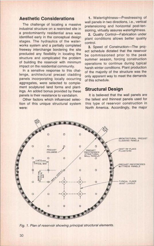
The resulting capacity of the reservoir,including live and dead load storage. isapproximately 9,400.000 imperial gal-lons (41.6 million liters). Figs. 1 and 2show in plan and cross section, respec-tively, the general configuration of thereservoir structure.
28

An all precast prestressed concrete system provedto be structurally efficient and economical inbuilding a 10-million gallon water storage reservoirin Regina, Saskatchewan. Nearly 600 precast units(comprising structural wall panels, buttress panels,hollow-core roof members, roof support girders,columns, and architectural cladding panels) were
used in the project.
On this basis, four alternate structuralsystems were assessed:
— Conventionally reinforced, cast-in-place concrete;
— Post-tensioned cast-in-place con-crete:
—Wire wound, prestressed concrete;and
— Precast prestressed concrete.
In addition to the above concrete
systems, the possibility of using astructural steel tank was investigatedand a cursory review of several patentedsystems was undertaken, but none ofthose systems proved to be suitable oreconomical.
A preliminary cost analysis showedthat the precast prestressed concretealternative would produce an apparentcost saving between 5 to 10 percentover the other structural systems.
rJ
ry :'`d ^s s^^} Fibs 3°^"^ s
^' 1ae Vie? k:_
Completed reservoir (July 10, 1980). Freeway detour in foreground will beabandoned and replaced by a ttractive landscaping.
PCI JOURNALJNovember-December 1980 29
Aesthetic ConsiderationsThe challenge of locating a massive
industrial structure on a restricted site ina predominantly residential area wasidentified early in the conceptual designstages. The hydraulics of the water-works system and a partially completedfreeway interchange bordering the siteprecluded any flexibility in locating thestructure and complicated the problemof building the reservoir with minimumimpact on the residential community.
In a sensitive response to this chal-lenge, architectural precast claddingpanels incorporating locally occurringaggregates, were selected to comple-ment sculptured land forms and plant-ings. An added bonus provided by thesepanels is their resistance to vandalism.
Other factors which influenced selec-tion of this unique structural systemwere:
1. Watertightness—Prestressing ofwall panels in two directions, i.e., verticalpretensioning and horizontal post-ten-sioning, virtually assures watertightness.
2. Quality Control—Fabrication underplant conditions allows better qualitycontrol.
3. Speed of Construction—The proj-ect schedule dictated that the reservoirbe commissioned prior to the peaksummer season, forcing constructionoperations to continue during typicalharsh winter conditions. Plant productionof the majority of the structure was theonly apparent way to meet the demandsof this schedule.
Structural DesignIt is believed that the wall panels are
the tallest and thinnest panels used forthis type of reservoir construction inNorth America. Accordingly, the major
0 0 0ARCHITECTURAL PRECASTCLADDING PANELS
0 D 0/1.,EC'A,..T,
DPRECAST
IPLAS N-PLACECOLUMNS EO
PILASTERS
0 011470 ,n,e,
TYPICAL BAY
EE ^¢
am
L
0 / a
0
0 /0 0
PRECAST PRESTRESSED`BUTTRESS PANELS
00
\q ^___^'O'--' 0 _ TYPICAL FLOOR1, JQENT LAYOUTI Y^ I.l A
0 q
Fig. 1. Plan of reservoir showing principal structural elements.
30

0
portion of the structural design was de-voted to analyzing the prestressed,post-tensioned, precast concrete wallpanels. The walls were analyzed usingthe theory of Timoshenko,' the PCA de-sign aid Circular Tanks Without Pre-stressing, z and GTA's Technical Bulletin77-81.3
A preliminary design was performed toobtain an estimate of wall thickness re-quired. The typical wall panel and but-tress panel sizes were then determinedconsidering the geometric constraints,the precast concrete plant crane capac-ity, the quality control requirements, andthe erection problems. The cast-in-placeconcrete pilasters were sized withminimum dimensions that would stillallow practical placement of the concreteand maintain quality control. The pilas-ters are heavily reinforced to controlshrinkage cracks.
Fig. 3 illustrates the essential featuresof the structural wall panels and de-scribes the function of the critical topand bottom joints. The basic configura-tion of the buttress panels and thecast-in-place pilasters are shown in Fig.4.
The wall panels were prestressed ver-tically in order to resist the applied verti-cal bending due to the water pressureand due to the earth backfill pressure. Itwas found during the design that thevertical prestressing requirements were
r^•
IIIIL # f
Closeup of architectural precastcladding panels (July 10, 1980) -Sixty-six 6-in. (152 mm) thick panelswere used in the reservoir comprising atotal wall area of about 15,240 sq ft(1416 m2).
PRECAST . PRESTRESSED"HOLLOW CORE" ROOF
-PRECASTPRESTRESSED PRECAST iIRUCYURAL WALL COLUMNSINELS HEIGHT= '-^^ G m (38lt.1 Wa
_ a .
._ T ---- --- ---- a E,`APPROKiMATE ' ^vGACKFILL LINE -
S .
`CAST-iN-PLACE 'CASTPRESTRESSED FOOTING FLOC
ARCHITECTURAL PRECAST--..CLADDINO PANELS
s`—J7—PRECAST FSLPRESTRESSEDROOF SUPPORT
GIRDERS I !
-qII ^
f- N-PLACE ! ``HSTALS `T L HEIGHT NTTOM
O AINT'AIN CONSTANTCOLUMN HEIGHT
Fig. 2. Cross section of reservoir showing structural components.
PCI JOURNAL/November-December 1980 31

230mm
PARAPET(ADDED LATER)
PRECAST PRESTRESSEDHOLLOW-CORE ROOF
E
ii;RUBBER BEARING PAD
PRECAST PRESTRESSEDWALL PANELSR
POST-TENSIONING DUCTPILASTER
PRECAST PRESTRESSEDWALL PANELS
POST-TENSIONING DUCT
^01 SEALANT
GROUT ^lSTEP 1
POCKET INCAST-IN-PLACEPERIMETER FOOTING
Note 1 The top joint separates the wall fromthe root to allow movement due topost-tensioning, temperature changes, andlateral water pressure.
Note 2: The grouted joint at the base of thewall panels provides a structural hinge. Thesealant provides watertightness.
Fig. 3. Joint details of precastprestressed wall panels.
the major criteria in determining the re-quired concrete compressive strength.
The critical section in the wall panel isat the location of the post-tensioningducts. The reduced width at the sides ofthe duct requires a high concrete strengthat release in order to accommodate thehigh prestressing forces. During the de-sign, it was confirmed that a release
strength of 4350 psi (30 MPa) and an ul-timate strength of 6500 psi (45 MPa)were required.
Once the hoop stresses were calcu-lated, the post-tensioning requirementswere easily determined. The practicallimitations of bringing the ducts out atthe buttress panels had to be studiedbefore the spacing of the ducts could be
PRECAST PRESTRESSED CONCRETE COMPONENTS
Type ofElement Number
Dimensions
U.S. Units Metric Units
StructuralWall Panels 60 9 in. thick x 10 ft wide x 38 ft 0.23 x 3.05 x 11.6 mButtressPanels 6 18 in. thick x 6.4 ft wide x 38 ft 0.46 x 1.95 x 11.6 m
Hollow-Core 8 in. deep x 4 ft wideRoof Members 368 (Tata' Area = 39.760 sq ft) 0.20 x 1.22 m (Area = 3694 mz)
Roof Support 3.6 ft deepGirders 38 (Total Length = 1350 ft) 1.17m deep (Length – 412m)
Columns 31 20 in. x 20 in. x 33 ft 0.50 x 0.50 x 10.13 m
ArchitecturalCladding 6 in. thick 0.15 m thickPanels 66 (Total Area = 15.240 sq ft) (Area = 1416 rrt2(
32
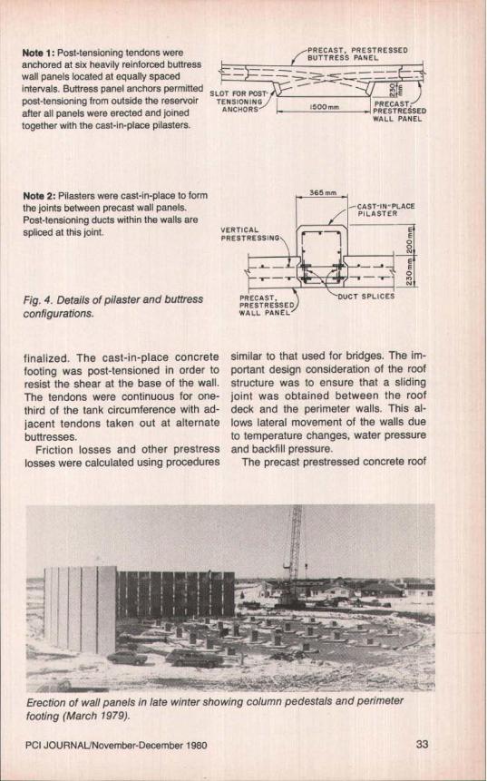
Note 1: Post-tensioning tendons were PRECAST, PRESTRESSED
anchored at six heavily reinforced buttress BUTTRESS PANEL
wall panels located at equally spaced —~intervals. Buttress panel anchors permitted SLOT FOR POST-
^^` MBEpost-tensioning from outside the reservoir TENSIONING
cutEPRECAST,
after all panels were erected and joined ANCHORS 500 mm PRESTRESSED
together with the cast-in-place pilasters.WALL PANEL
Note 2: Pilasters were cast-in-place to formthe joints between precast wall panels.Post-tensioning ducts within the walls arespliced at this joint. VERTICAL
PRESTRE5S1
365 mm
CAST-IN-PLACEPILASTER
Fig. 4. Details of pilaster and buttressconfigurations.
finalized. The cast-in-place concretefooting was post-tensioned in order toresist the shear at the base of the wall.The tendons were continuous for one-third of the tank circumference with ad-jacent tendons taken out at alternatebuttresses.
Friction losses and other prestresslosses were calculated using procedures
PRECAST, DUCT SPLICESPRESTRESSEDWALL PANEL
similar to that used for bridges. The im-portant design consideration of the roofstructure was to ensure that a slidingjoint was obtained between the roofdeck and the perimeter walls. This al-lows lateral movement of the walls dueto temperature changes, water pressureand backfill pressure.
The precast prestressed concrete roof
^' r
Erection of wall panels in late winter showing column pedestals and perimeterfooting (March 1979).
PCI JOURNALJNovember-December 1980 33

I
Erection of wall panels (March 1979). Snow has blown on to the panels.
General view of interior of reservoir (May 1979).
34

General view of reservoir with wall panels installed (May 1979).
Pilasters and abutments are complete; post-tensioningtendons have been installed (June 1979).
Parapet forms in place (July 1979).
PCI JOURNAL/November-December 1980 35

General view of reservoir (November 1979).
deck, precast prestressed roof beamsand precast concrete columns were de-signed in accordance with standardpractice. The bases for the precast col-umns were varied in height to allow thelength of the precast columns to remainconstant.
CostThe total cost of the reservoir project
(which included rerouting of frontageroads, extensive piping, landscapingplus other items) amounted to about 2.3million Canadian dollars. The structuralportion of the project cost about 17Canadian cents per gallon of water.
A short construction strike, adversewinter conditions and an exceptionallylate spring delayed construction opera-tions, but the reservoir was ready for useby July, 1979. Since then the reservoirhas been functioning satisfactorily.
Concluding RemarksThe early performance of the North
West Reservoir has justified the selec-tion of the PSP (precast, segmental,post-tensioned system). Prestressing ofthe wall panels in two directions virtuallyassures watertightness of the walls, ifspecial attention is paid to pilaster con-struction and the wall-to-footing joint.
In addition to the satisfactory service-ability of the reservoir structure, the
project has provided a net gain for theresidents of the area, in that a neighbor-hood park, with eye-pleasing architec-tural precast panels providing a back-drop to the landscape and a buffer to theinterchange, will be created for year-round recreation.
CreditsPrime Consultant and Design Engineer:
Reid, Crowther & Partners Limited,Regina, Saskatchewan.
Consulting Architect: Wiens & As-sociates Ltd., Regina, Saskatchewan.
General Contractor: PCL ConstructionLtd., Regina, Saskatchewan.
Precast Concrete Manufacturer: Con-Force Products Limited, Regina,Saskatchewan.
Owner: City of Regina, Saskatchewan.
References1. Timoshenko, S., and Woinowsky-Kreiger,
S., Theory of Plates and Shells, SecondEdition, McGraw-Hill Book Co., New York,N. Y., 1959.
2. Circular Tanks Without Prestressing(1S072), Portland Cement Association,Skokie, Illinois.
3. Precast Segmental Post-Tensioned (PSP)Concrete Tanks for Water and OtherLiquids, Technical Bulletin 77-81, Con-crete Technology Associates, Tacoma,Washington, December 1977.
36