pre-engineered metal building fabrication - controlled automation inc
TRANSCRIPT

FLANGE PRODUCTION LINE
PRE-ENGINEERED METAL BUILDING FABRICATION
Flange ProductionLine
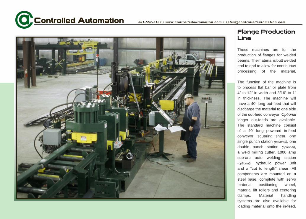
These machines are for the production of flanges for welded beams. The material is butt welded end to end to allow for continuous processing of the material.
The function of the machine is to process flat bar or plate from 4” to 12” in width and 3/16” to 1” in thickness. The machine will have a 40’ long out-feed that will discharge the material to one side of the out-feed conveyor. Optionallonger out-feeds are available.The standard machine consist of a 40’ long powered in-feed conveyor, squaring shear, one single punch station (optional), one double punch station (optional),a weld milling cutter, 1000 amp sub-arc auto welding station (optional), hydraulic power unit and a “cut to length” shear. All components are mounted on a steel base, complete with servo material positioning wheel, material lift rollers and centering clamps. Material handling systems are also available for loading material onto the in-feed.

Applications
Systems
welded beams
Features
speeds of 3 ft. per second
electronically
adjustment to compensate for unstraight material
monitoring for constant accuracy
with hydraulic hold-downs
measuring system
(250 ton optional)
(215 ton optional)
shear
auto welder
punch unit with available adapters

User Interface
control system has an easy to use interface. As the machine runs, the status of each part or operation changes in real-time. A part list dialog can be displayed to show which parts have been completed or which operations are remaining. The controller can be easily networked to the office computer network for downloading of parts produced in the office or by most drafting
also be easily programmed at the machine, even while another part is being run.
The Pre-Run Screen
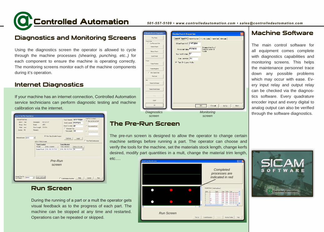
The pre-run screen is designed to allow the operator to change certain machine settings before running a part. The operator can choose and verify the tools for the machine, set the materials stock length, change kerfs desired, modify part quantities in a mult, change the material trim length, etc….
Machine Software
The main control software for all equipment comes complete with diagnostics capabilities and monitoring screens. This helps the maintenance personnel trace down any possible problems which may occur with ease. Ev-ery input relay and output relay can be checked via the diagnos-tics software. Every quadrature encoder input and every digital to analog output can also be verified through the software diagnostics.
Diagnostics and Monitoring Screens
Using the diagnostics screen the operator is allowed to cycle through the machine processes (shearing, punching, etc..) foreach component to ensure the machine is operating correctly. The monitoring screens monitor each of the machine components during it’s operation.
Internet Diagnostics
service technicians can perform diagnostic testing and machine calibration via the internet.
Run Screen
visual feedback as to the progress of each part. The machine can be stopped at any time and restarted. Operations can be repeated or skipped.
Diagnosticsscreen
Monitoringscreen
Pre-Runscreen
Run Screen
Completedprocesses are indicated in red

In-feed Conveyor
The in-feed conveyor is powered by a servo motor and driven in
wheel drive and out-feed. There are a series of rolling centering clamps on the in-feed conveyor that align the material to the roller conveyor/ machine center line. The clamps are individually operated by the controller to ensure that the ends of the bar are aligned correctly with the datum line at all times. The operator can also operate the clamps manually to help center a new piece of material, or when using the squaring shear to trim the material end. The in-feed conveyor’s “end of material” photo-eye allows the controller to know where the end of the loaded material is, with respect to the holes in the part. The controller will trim the trailing end of the material in the squaring shear so the weld will not be within a programmable distance from a hole location.

Squaring Shear
The purpose of the squaring shear is to trim the trailing end of the material being processed and the leading
is to ensure accurate alignment for welding. The shear lowers when not in use, to prevent the material from dragging on the lower blades. The shear has manually operated hold-down clamps on the in-feed and out-feed sides of the frame that are operated independently. Once the trailing end of the part has been positioned by the computer, the operator will activate the out-feed clamp. If the trim location for the part is at the very end of the stock length, where the leading end of the
length will be positioned forward by the operator to butt against the trailing end of the first stock length. The operator will activate the in-feed hold-down clamp and in-feed conveyor centering clamps. The operator will then activate the squaring shear with dual palm buttons. If the material trailing end must be cut short to miss a hole location with the weld, the operator will cut the trailing end, remove the
length to cut the leading end to square it.

Sub-arc welder and clamp station
The main purpose for the weld station is to provide a stable location to splice material accurately every time. This is done with centering clamps (lateral
alignment) and hold down clamps (vertical alignment) on either side of the weld area. The hold downs also provide a ground that keeps stray currents form damaging the computer system.
The computer will position the trailing end of the in-process material to the correct location to weld.
The operator will move the square-cut material on the in-feed into the weld area, ensuring it is flush and has the proper gap with the in-process material. With the material square and clamped, the operator will manually start the sub-arc welding cycle. When the welding is complete, the operator
remove the slag.The opt ional sub-arc auto-welder can process a fu l l penetrat ion weld (usable in most construct ion)

Weld Mill
The purpose of the automated weld mill is to mill the weld flush with the material, at the center of the width of the material. This is so that when the flange is welded to the web, the weld will not keep the flange from being fully in contact with the web. This operation is fully automatic.
Servo pinch wheel system
The servo driven pinch wheel powers the material through the machine. An air cylinder clamps the material against the knurled drive rolls. The servo motor and
wheel, coupled to an encoder, gives the length measuring data to the computer. The air clamp cylinder is operated by a double solenoid, two position air valve. This ensures that an emergency stop situation will not allow the drive and measuring wheels to lose contact with the material. A material photo-eye on the out-feed side of the unit provides the reference point for the length measuring. A powered wire brush assembly cleans the material surface before it reaches the measuring wheel.

Cut to Length Shear
This unit is to cut the part to final length. It is a single cut shear (zero
kerf). It has integral hold-down and out-feed material support cylinders, which ensure square, clean cuts. It has the standard
as well as an encoder, to allow the shear to retract only enough to clear the material thickness being cut. This improves part production times.

Out-feed Conveyor
The flat out-feed conveyor is powered by a servo motor system
with the in-feed conveyor and center section pinchwheel. It features the same material centering clamps as the in-feed conveyor. Two photo-eyes located along the length of the out-feed conveyor are used to detect the completed part and initiate the dump process. Once the part is detected, the lift arms automatically raise to deliver the completed part to the desired dump location.
optional material catch racks

Single Punch Punching Unit(optional)
This optional unit is for punching single holes that would require more tonnage than the double unit can produce, and hole patterns that do not match the double punch tooling spacing. Multiple gages on the same part can be produced with this unit. This unit is a time proven design, also used
angle and flat bar processing line. The unit has material lift rollers to keep the material from dragging on the die seat.
HydraulicPositioning
The punch frames are positioned hydraulically using a computer controlled hydraulic valve system. The valve system provides fast, accurate positioning of the punch frames.
Material Probing
All material has some bow or curve. The heavier the material the harder it is for the curve to be taken out by the material
true material position with respect to the punch is always measured. This achieves greater hole accuracy when
only clamped on one side of the punch.
Stripper(shown below in yellow)
automatically operated hydraulic stripper to hold the material flat against the die while the punch is retracting. This provides better hole quality and longer tool life.

Interchangeable
Single Punch and Die Block Tonnage
143 Ton Punch Information(optional 215 ton available)
Shaped punches (non-round) can be
stem adapter is 143 ton(optional punch stem adapters available to
meet your tooling needs)
This single punch frame has an edge to center distance range of 1” - 12”.

Double Punch Punching Unit(optional)
This optional unit is to punch two holes at one time, (upper and lower
flange holes). The gage spacing between the holes is determined by interchangeable tooling that the operator installs in the punch unit. The unit has a gage probe to find the actual edge of the material. Since the material is centered on the machine and this unit always centers the punches to the center of the material, the unit only has to move enough in gage to compensate for sweep in the material. The unit has material lift rollers to keep the material from dragging on the die seats.
HydraulicPositioning
The punch frames are positioned hydraulically using a computer controlled hydraulic valve system. The valve system provides fast, accurate positioning of the punch frames.
Material lift rollers keep the material from rubbing on the die seat while positioning.
Gage Probe
The gage probe measures from the edge of the material and calculates the center of the material based on the material width. Each frame has a material probe with a rack and pinion measurement. Each time the frame starts a punch cycle, the frame positions in gage relative to the true material position - not theoretical like most machines.
Stripper(shown above in yellow)
operated hydraulic stripper to hold the material, on both sides of the punches, flat against the die while the punch is retracting. This gives
life.

Double Punch and Die Block Tonnage
215 Ton Punch Information(optional 250 ton available)
(1-5/16” optional)
Shaped punches can not be used
holders. Special optional punchholders for use with shaped punches are available at an additional cost.
ton total due to cylinder.
2-1/4” - 6”
2-1/4" TO6" GAGE
Optional shimallows for
step punching
Interchangeable
Interchangeable
Set screw preventscoupling nut
from unscrewing
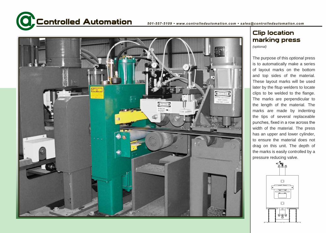
Clip location marking press (optional)
The purpose of this optional press is to automatically make a series of layout marks on the bottom and top sides of the material. These layout marks will be used later by the fitup welders to locate clips to be welded to the flange. The marks are perpendicular to the length of the material. The marks are made by indenting the tips of several replaceable
width of the material. The press has an upper and lower cylinder, to ensure the material does not drag on this unit. The depth of the marks is easily controlled by a pressure reducing valve.
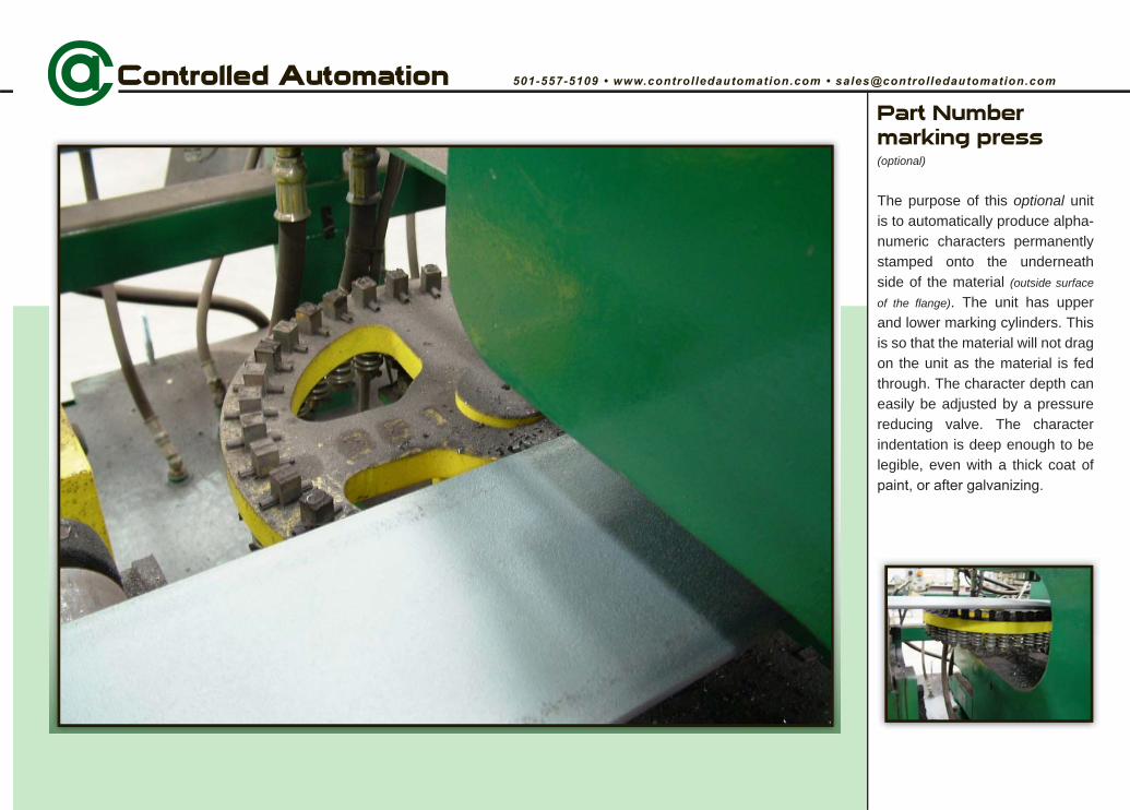
Part Number marking press (optional)
The purpose of this optional unitis to automatically produce alpha-numeric characters permanently stamped onto the underneath side of the material (outside surface
of the flange). The unit has upper and lower marking cylinders. This is so that the material will not drag on the unit as the material is fed through. The character depth can easily be adjusted by a pressure reducing valve. The character indentation is deep enough to be legible, even with a thick coat of

Hydraulic Power Unit
is a time proven, dual pump design, that gives long trouble free service life, as well as sufficient power for high speed production.
Service Panel
standard with a machine electrical distribution service panel. The purpose of the service panel is to distribute the appropriate voltage to the electrical components of the machine, and to ensure clean, controlled and protected circuits.
the drive isolation transformer, constant voltage regulator, control voltage transformer and fused disconnects for the machine.
(electrical distribution service panel)

Flange Production Line Specifications
Accuracy 1/32” electronically
Hydraulic Power Unit
Thermostat/oil heater Included
For more complete information on this or any of our machines, contact our sales department at 501-557-5109
shear strength
(for standard machine)
(60’ optional with additional in-feed)
Minimum initial bar length 6’
shear strength only (1-3/4” with optional coupling nut)
shear strengthshear strength
shear strength
shear strengthshear strength
Kerf 0”

© 2008 Controlled Automation, Inc.
Controlled Automation specializes in the manufacture of automated structural steel drilling, punching, and shape cutting machinery. We also build material handling systems to complement each type of machine we offer. As well as new
machinery, we are the industry leader in retrofitting control systems and remanufacturing existing structural steel fabricating machinery. All machines and controls are designed and manufactured entirely in the United States of America. All software is
developed and supported in the United States of America.
501-557-5109501-557-5618 Fax
US Mail PO Box 888
Bryant, AR 72089USA
Manufacturing facility 15701 West Sardis Road
Bauxite, AR 72011USA