powerpoint ® presentation unit 42 floor framing floor unit resting on sill plates floor unit...
TRANSCRIPT
PowerPoint® PresentationPowerPoint® Presentation
Unit 42Unit 42Floor FramingFloor Framing
Floor Unit Resting on Sill Plates • Floor Unit Resting on Cripple Walls •
Posts and Beams • Floor Joists • Subfloor • Floor Underlayment • Floor
Trusses • Wood I-joists
Floor Unit Resting on Sill Plates • Floor Unit Resting on Cripple Walls •
Posts and Beams • Floor Joists • Subfloor • Floor Underlayment • Floor
Trusses • Wood I-joists
Unit 42 — Floor FramingUnit 42 — Floor Framing
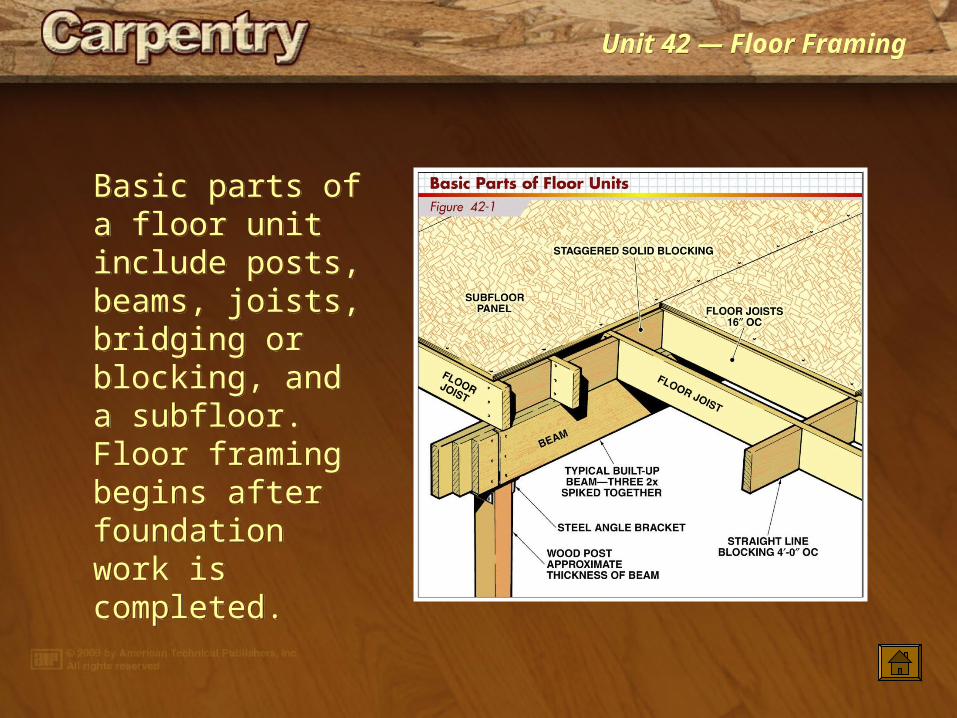
Basic parts of a floor unit include posts, beams, joists, bridging or blocking, and a subfloor. Floor framing begins after foundation work is completed.
Basic parts of a floor unit include posts, beams, joists, bridging or blocking, and a subfloor. Floor framing begins after foundation work is completed.
Unit 42 — Floor FramingUnit 42 — Floor Framing
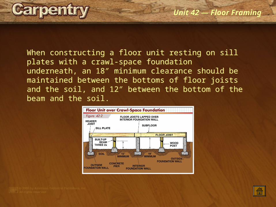
When constructing a floor unit resting on sill plates with a crawl-space foundation underneath, an 18″ minimum clearance should be maintained between the bottoms of floor joists and the soil, and 12″ between the bottom of the beam and the soil.
When constructing a floor unit resting on sill plates with a crawl-space foundation underneath, an 18″ minimum clearance should be maintained between the bottoms of floor joists and the soil, and 12″ between the bottom of the beam and the soil.
Unit 42 — Floor FramingUnit 42 — Floor Framing
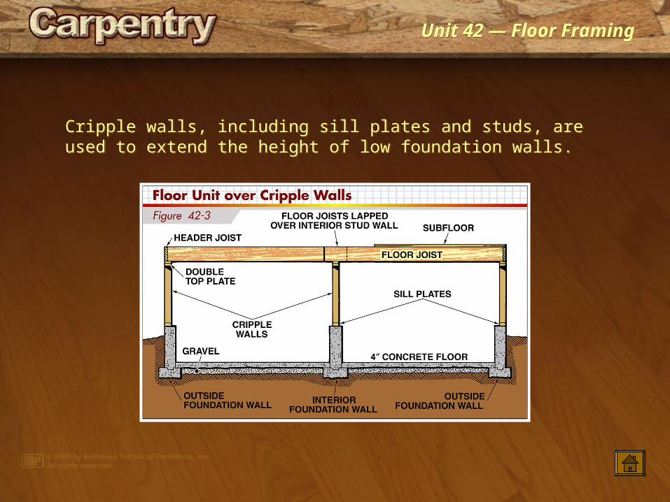
Cripple walls, including sill plates and studs, are used to extend the height of low foundation walls.Cripple walls, including sill plates and studs, are used to extend the height of low foundation walls.

Unit 42 — Floor FramingUnit 42 — Floor Framing
Posts are fastened at the top of the pier and at the bottom of the beam.
Posts are fastened at the top of the pier and at the bottom of the beam.

Unit 42 — Floor FramingUnit 42 — Floor Framing
No bolts or other types of fasteners are necessary to secure the fixed post bases to concrete; the lower section of the base is set into a concrete pier when concrete is placed. An adjustable post base should have 1″ to 2 1/2″ standoff height above the concrete. An adjustable base is secured in position by drilling a hole into hardened concrete and fixing a threaded rod into place with epoxy, or by setting a J-bolt into fresh concrete.
No bolts or other types of fasteners are necessary to secure the fixed post bases to concrete; the lower section of the base is set into a concrete pier when concrete is placed. An adjustable post base should have 1″ to 2 1/2″ standoff height above the concrete. An adjustable base is secured in position by drilling a hole into hardened concrete and fixing a threaded rod into place with epoxy, or by setting a J-bolt into fresh concrete.

Unit 42 — Floor FramingUnit 42 — Floor Framing
Metal post caps tie together posts and beams.
Metal post caps tie together posts and beams.
Unit 42 — Floor FramingUnit 42 — Floor Framing
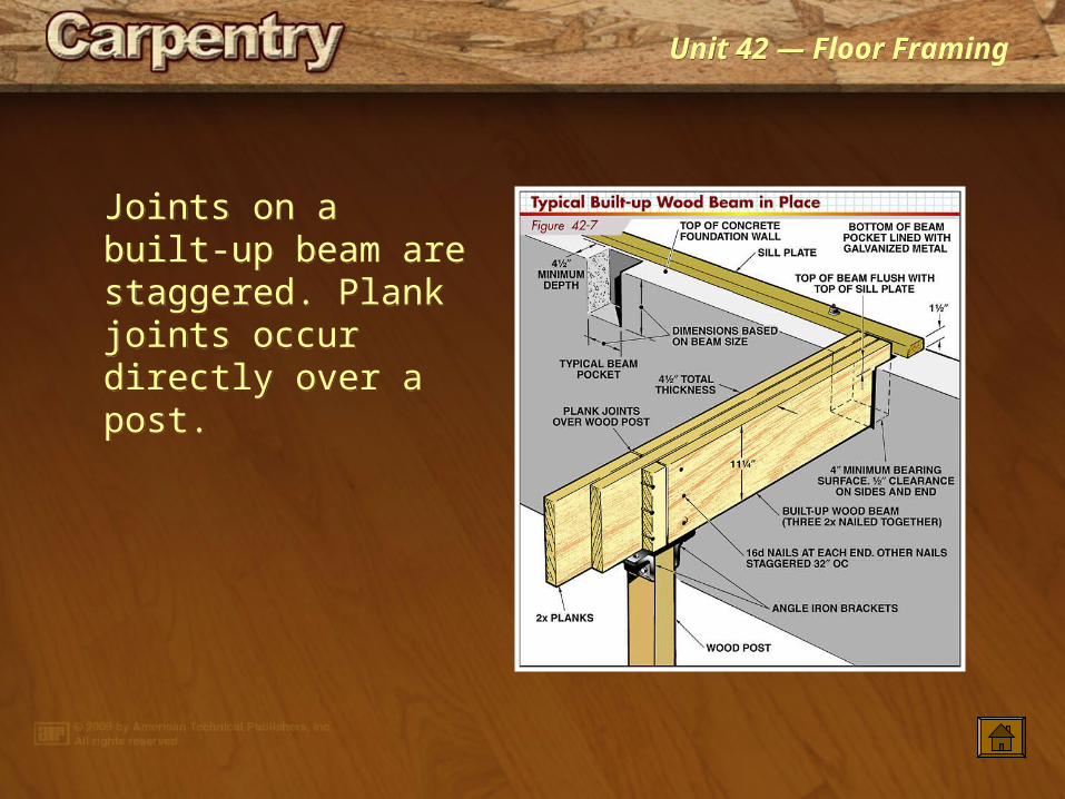
Joints on a built-up beam are staggered. Plank joints occur directly over a post.
Joints on a built-up beam are staggered. Plank joints occur directly over a post.

Unit 42 — Floor FramingUnit 42 — Floor Framing
Allowable beam sizes are based on the span of supported flooring, clear opening, lumber grade, and live and dead loads. This table is for a floor beam supporting a 40 psf live load and 10 psf dead load.
Allowable beam sizes are based on the span of supported flooring, clear opening, lumber grade, and live and dead loads. This table is for a floor beam supporting a 40 psf live load and 10 psf dead load.
Unit 42 — Floor FramingUnit 42 — Floor Framing
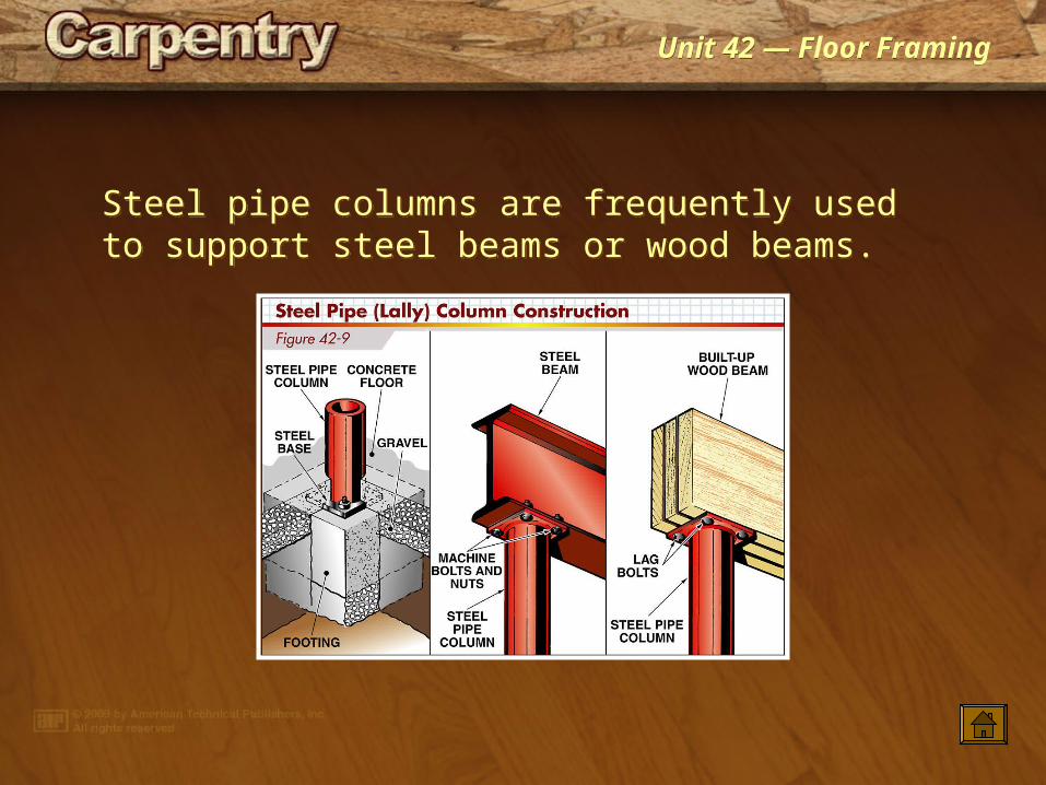
Steel pipe columns are frequently used to support steel beams or wood beams.Steel pipe columns are frequently used to support steel beams or wood beams.

Unit 42 — Floor FramingUnit 42 — Floor Framing
A hollow steel section column may be used to support the end of an LVL beam.
A hollow steel section column may be used to support the end of an LVL beam.
Unit 42 — Floor FramingUnit 42 — Floor Framing
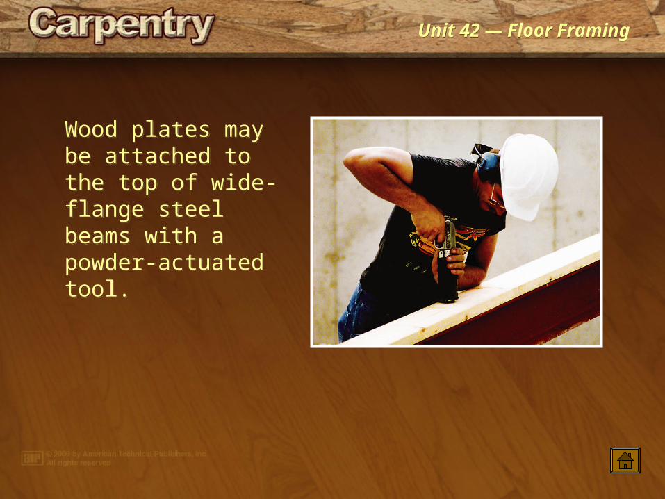
Wood plates may be attached to the top of wide-flange steel beams with a powder-actuated tool.
Wood plates may be attached to the top of wide-flange steel beams with a powder-actuated tool.

Unit 42 — Floor FramingUnit 42 — Floor Framing
When placing wood posts and beams, the top of each beam should be aligned with the upper surface of the sill plate.
When placing wood posts and beams, the top of each beam should be aligned with the upper surface of the sill plate.

Unit 42 — Floor FramingUnit 42 — Floor Framing
Allowable floor joist spans are based on the lumber species and grade, and joist size and spacing.
Allowable floor joist spans are based on the lumber species and grade, and joist size and spacing.
Unit 42 — Floor FramingUnit 42 — Floor Framing
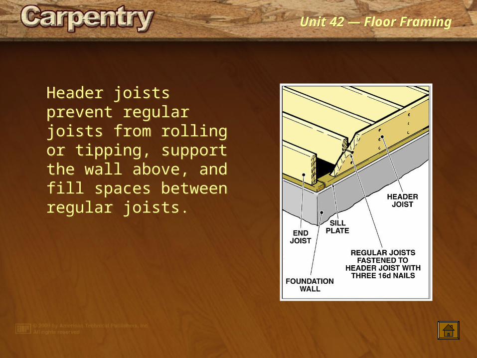
Header joists prevent regular joists from rolling or tipping, support the wall above, and fill spaces between regular joists.
Header joists prevent regular joists from rolling or tipping, support the wall above, and fill spaces between regular joists.
Unit 42 — Floor FramingUnit 42 — Floor Framing
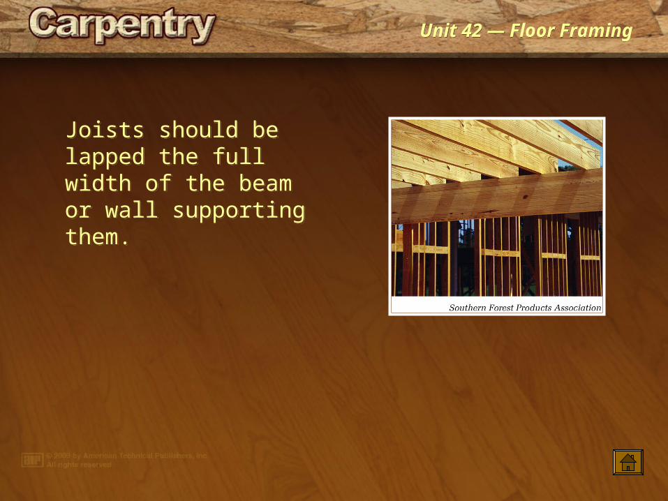
Joists should be lapped the full width of the beam or wall supporting them.
Joists should be lapped the full width of the beam or wall supporting them.
Unit 42 — Floor FramingUnit 42 — Floor Framing
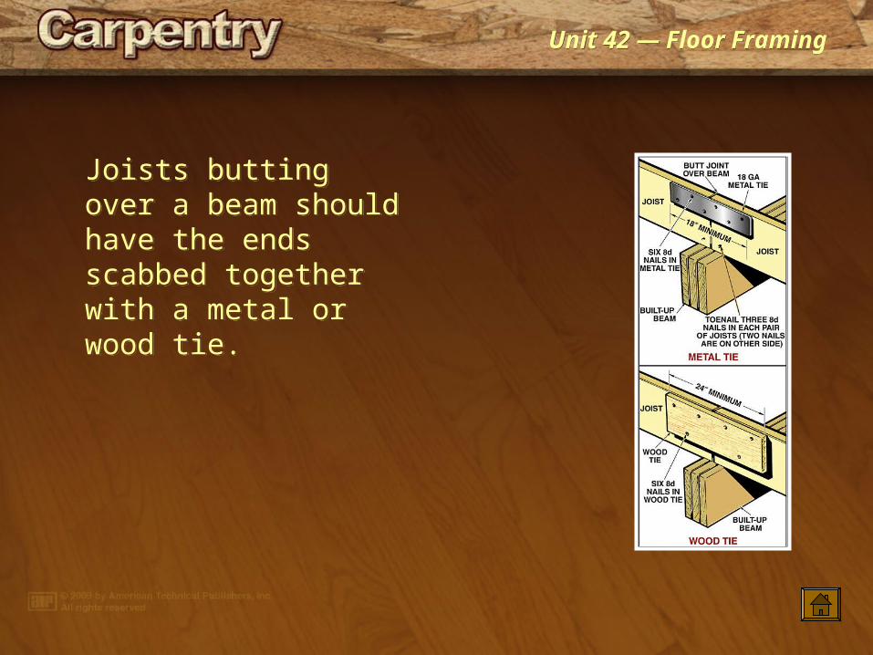
Joists butting over a beam should have the ends scabbed together with a metal or wood tie.
Joists butting over a beam should have the ends scabbed together with a metal or wood tie.
Unit 42 — Floor FramingUnit 42 — Floor Framing
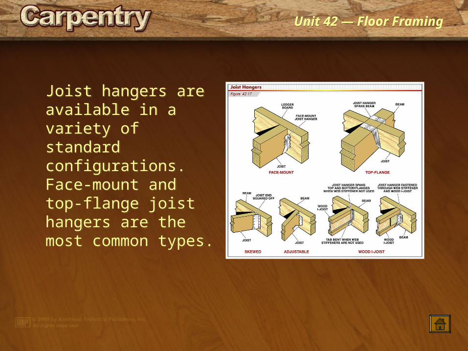
Joist hangers are available in a variety of standard configurations. Face-mount and top-flange joist hangers are the most common types.
Joist hangers are available in a variety of standard configurations. Face-mount and top-flange joist hangers are the most common types.
Unit 42 — Floor FramingUnit 42 — Floor Framing
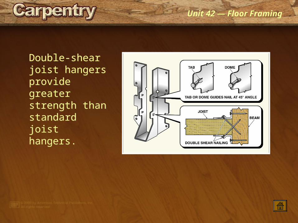
Double-shear joist hangers provide greater strength than standard joist hangers.
Double-shear joist hangers provide greater strength than standard joist hangers.
Unit 42 — Floor FramingUnit 42 — Floor Framing
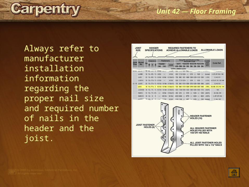
Always refer to manufacturer installation information regarding the proper nail size and required number of nails in the header and the joist.
Always refer to manufacturer installation information regarding the proper nail size and required number of nails in the header and the joist.
Unit 42 — Floor FramingUnit 42 — Floor Framing
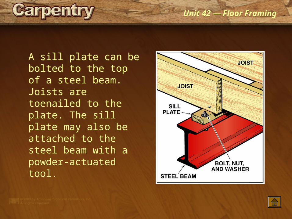
A sill plate can be bolted to the top of a steel beam. Joists are toenailed to the plate. The sill plate may also be attached to the steel beam with a powder-actuated tool.
A sill plate can be bolted to the top of a steel beam. Joists are toenailed to the plate. The sill plate may also be attached to the steel beam with a powder-actuated tool.
Unit 42 — Floor FramingUnit 42 — Floor Framing
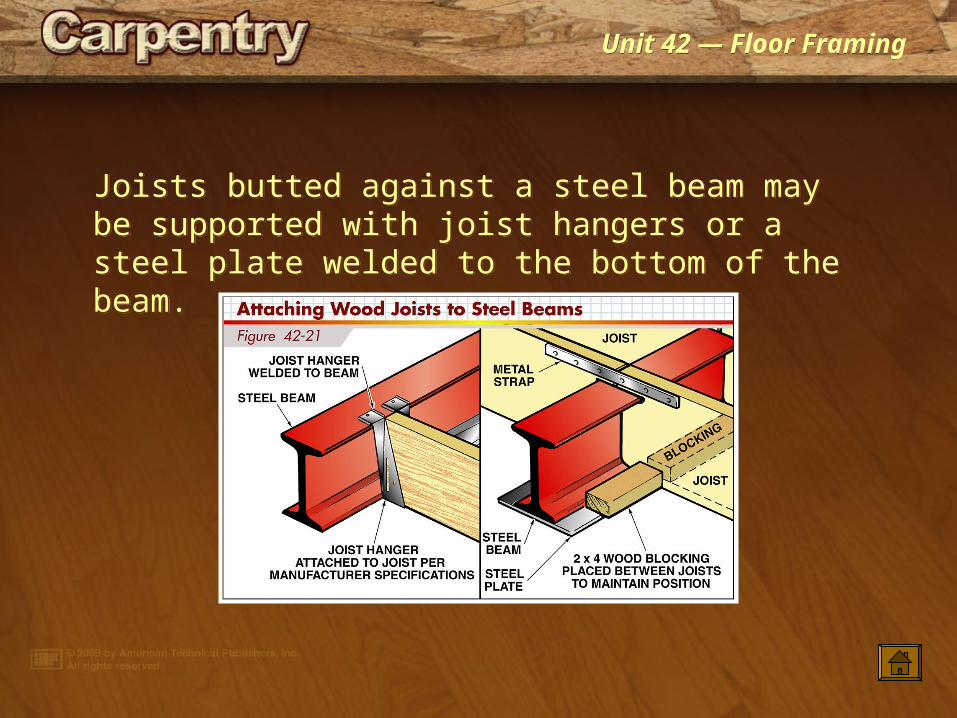
Joists butted against a steel beam may be supported with joist hangers or a steel plate welded to the bottom of the beam.
Joists butted against a steel beam may be supported with joist hangers or a steel plate welded to the bottom of the beam.
Unit 42 — Floor FramingUnit 42 — Floor Framing
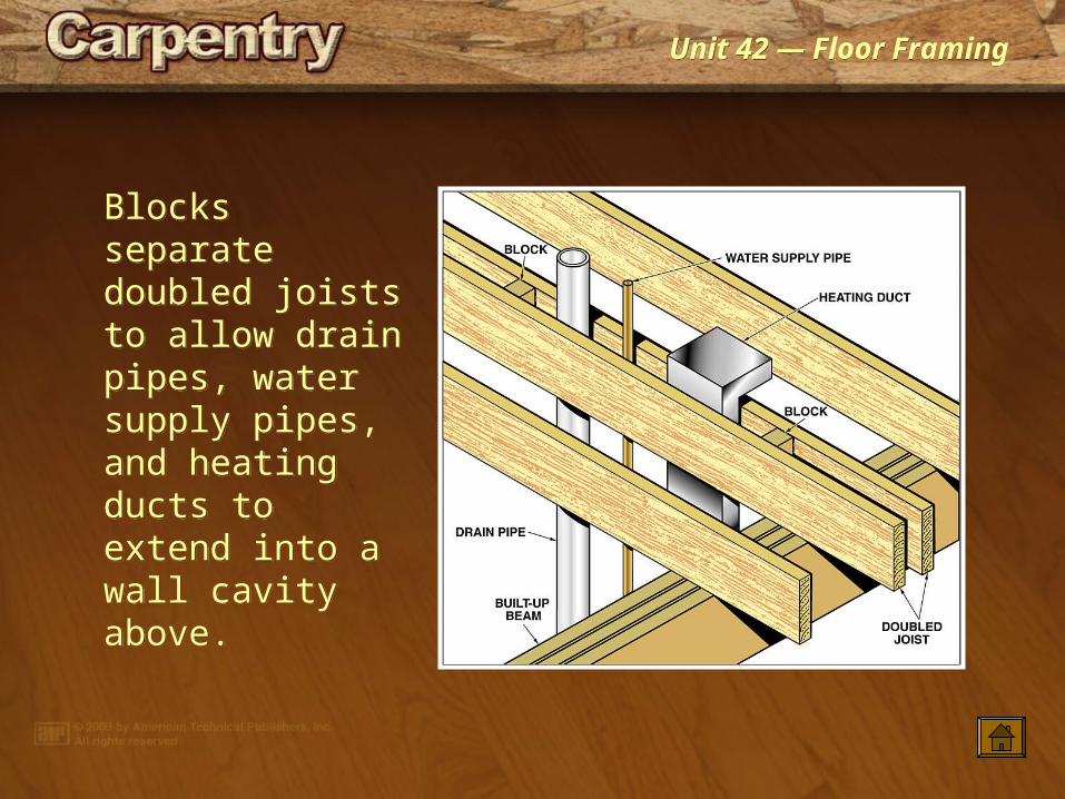
Blocks separate doubled joists to allow drain pipes, water supply pipes, and heating ducts to extend into a wall cavity above.
Blocks separate doubled joists to allow drain pipes, water supply pipes, and heating ducts to extend into a wall cavity above.
Unit 42 — Floor FramingUnit 42 — Floor Framing
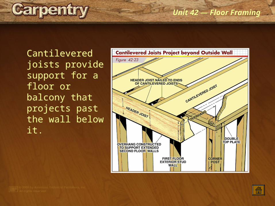
Cantilevered joists provide support for a floor or balcony that projects past the wall below it.
Cantilevered joists provide support for a floor or balcony that projects past the wall below it.
Unit 42 — Floor FramingUnit 42 — Floor Framing
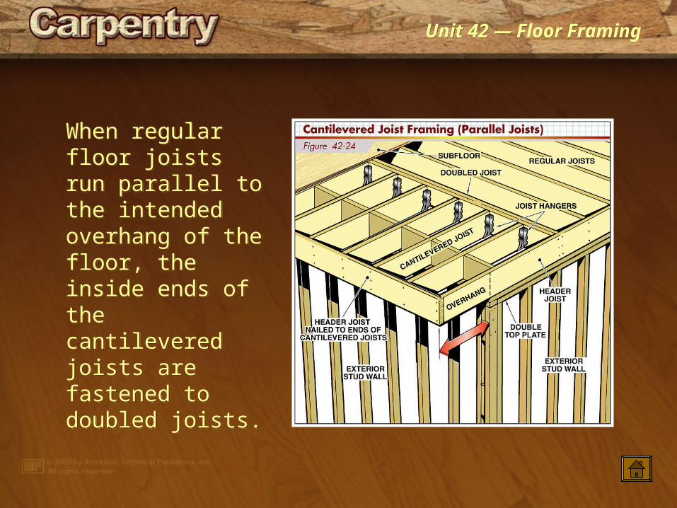
When regular floor joists run parallel to the intended overhang of the floor, the inside ends of the cantilevered joists are fastened to doubled joists.
When regular floor joists run parallel to the intended overhang of the floor, the inside ends of the cantilevered joists are fastened to doubled joists.
Unit 42 — Floor FramingUnit 42 — Floor Framing
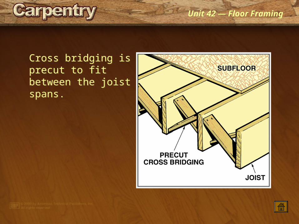
Cross bridging is precut to fit between the joist spans.
Cross bridging is precut to fit between the joist spans.
Unit 42 — Floor FramingUnit 42 — Floor Framing
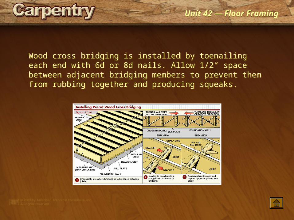
Wood cross bridging is installed by toenailing each end with 6d or 8d nails. Allow 1/2″ space between adjacent bridging members to prevent them from rubbing together and producing squeaks.
Wood cross bridging is installed by toenailing each end with 6d or 8d nails. Allow 1/2″ space between adjacent bridging members to prevent them from rubbing together and producing squeaks.
Unit 42 — Floor FramingUnit 42 — Floor Framing
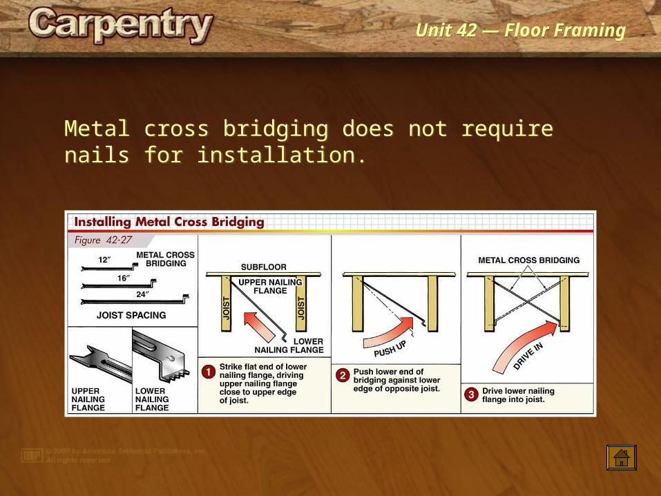
Metal cross bridging does not require nails for installation.Metal cross bridging does not require nails for installation.
Unit 42 — Floor FramingUnit 42 — Floor Framing
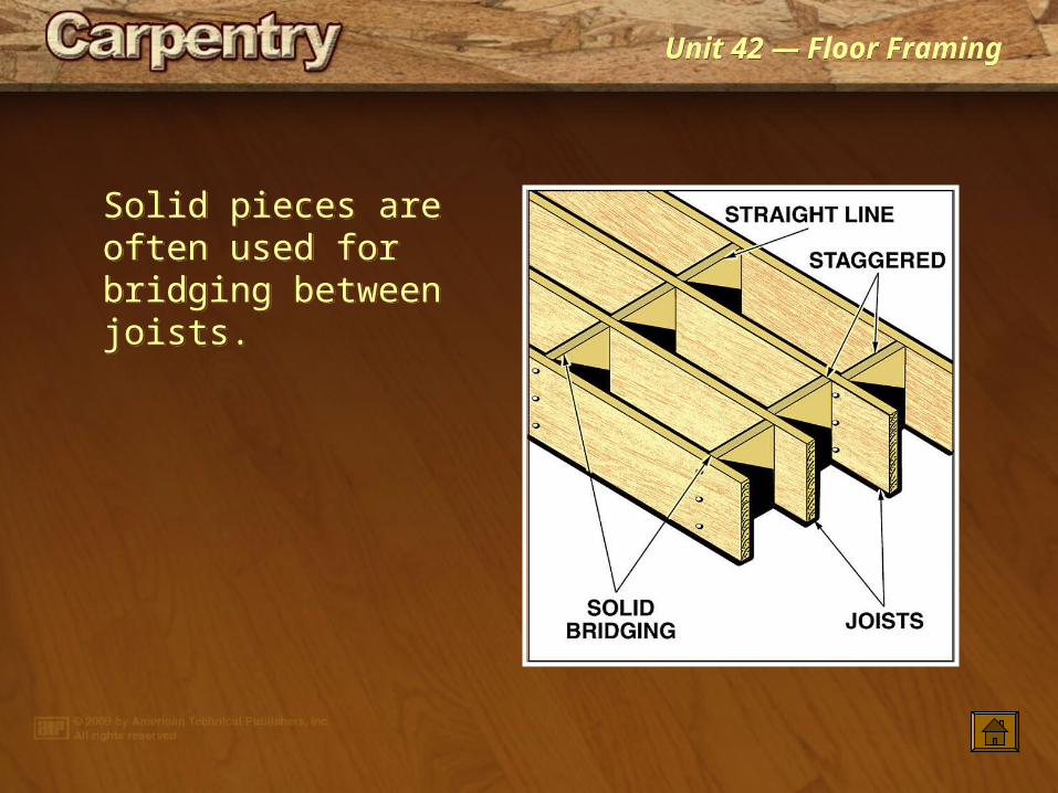
Solid pieces are often used for bridging between joists.
Solid pieces are often used for bridging between joists.
Unit 42 — Floor FramingUnit 42 — Floor Framing
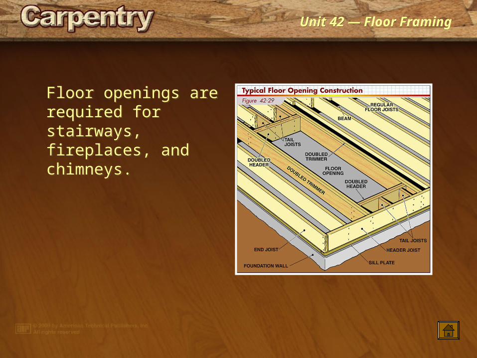
Floor openings are required for stairways, fireplaces, and chimneys.
Floor openings are required for stairways, fireplaces, and chimneys.
Unit 42 — Floor FramingUnit 42 — Floor Framing
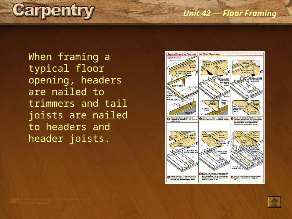
When framing a typical floor opening, headers are nailed to trimmers and tail joists are nailed to headers and header joists.
When framing a typical floor opening, headers are nailed to trimmers and tail joists are nailed to headers and header joists.
Unit 42 — Floor FramingUnit 42 — Floor Framing
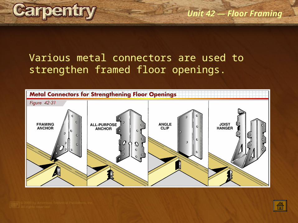
Various metal connectors are used to strengthen framed floor openings.Various metal connectors are used to strengthen framed floor openings.
Unit 42 — Floor FramingUnit 42 — Floor Framing
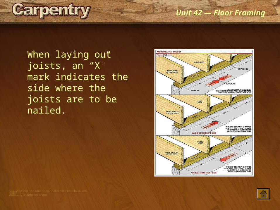
When laying out joists, an “X” mark indicates the side where the joists are to be nailed.
When laying out joists, an “X” mark indicates the side where the joists are to be nailed.
Unit 42 — Floor FramingUnit 42 — Floor Framing
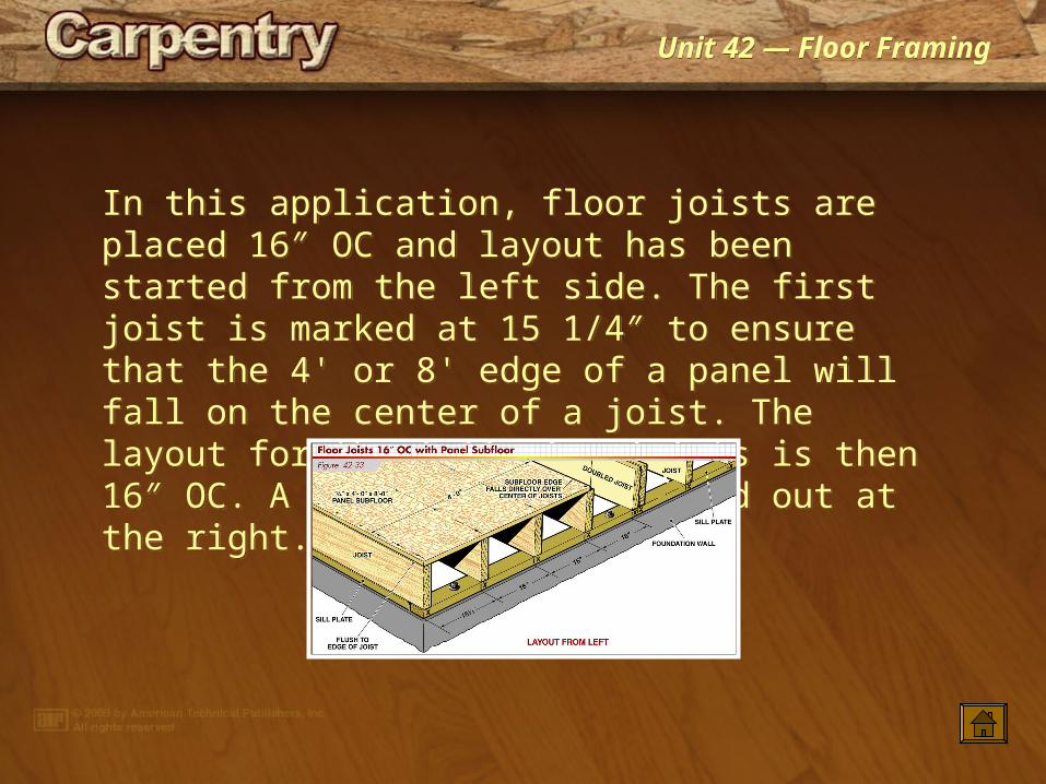
In this application, floor joists are placed 16″ OC and layout has been started from the left side. The first joist is marked at 15 1/4″ to ensure that the 4' or 8' edge of a panel will fall on the center of a joist. The layout for the following joists is then 16″ OC. A doubled joist is laid out at the right.
In this application, floor joists are placed 16″ OC and layout has been started from the left side. The first joist is marked at 15 1/4″ to ensure that the 4' or 8' edge of a panel will fall on the center of a joist. The layout for the following joists is then 16″ OC. A doubled joist is laid out at the right.
Unit 42 — Floor FramingUnit 42 — Floor Framing
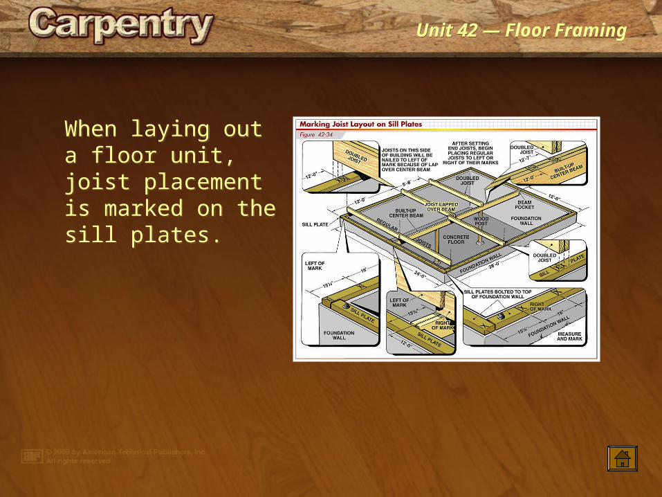
When laying out a floor unit, joist placement is marked on the sill plates.
When laying out a floor unit, joist placement is marked on the sill plates.

Unit 42 — Floor FramingUnit 42 — Floor Framing
A floor unit is framed by setting the header and end joists, placing the floor joists, and installing blocking and bridging. The floor opening is framed as described in Figure 42-30. Most framing members should be precut before construction begins.
A floor unit is framed by setting the header and end joists, placing the floor joists, and installing blocking and bridging. The floor opening is framed as described in Figure 42-30. Most framing members should be precut before construction begins.
Unit 42 — Floor FramingUnit 42 — Floor Framing
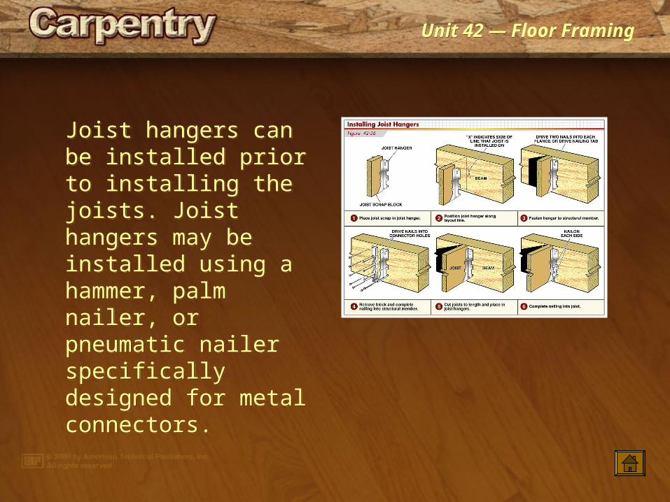
Joist hangers can be installed prior to installing the joists. Joist hangers may be installed using a hammer, palm nailer, or pneumatic nailer specifically designed for metal connectors.
Joist hangers can be installed prior to installing the joists. Joist hangers may be installed using a hammer, palm nailer, or pneumatic nailer specifically designed for metal connectors.
Unit 42 — Floor FramingUnit 42 — Floor Framing
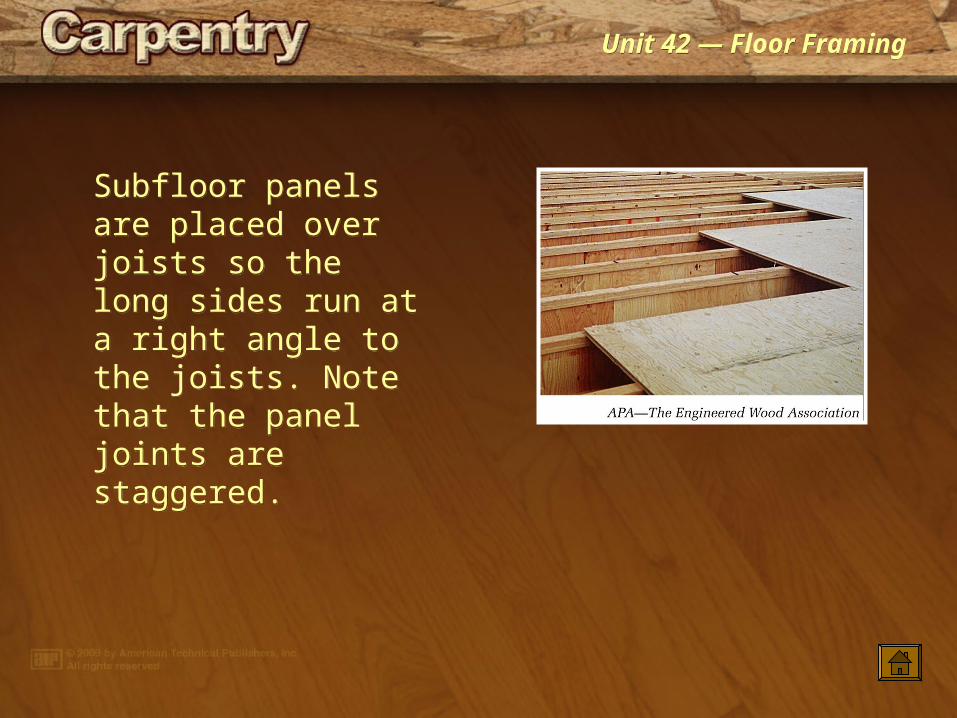
Subfloor panels are placed over joists so the long sides run at a right angle to the joists. Note that the panel joints are staggered.
Subfloor panels are placed over joists so the long sides run at a right angle to the joists. Note that the panel joints are staggered.
Unit 42 — Floor FramingUnit 42 — Floor Framing
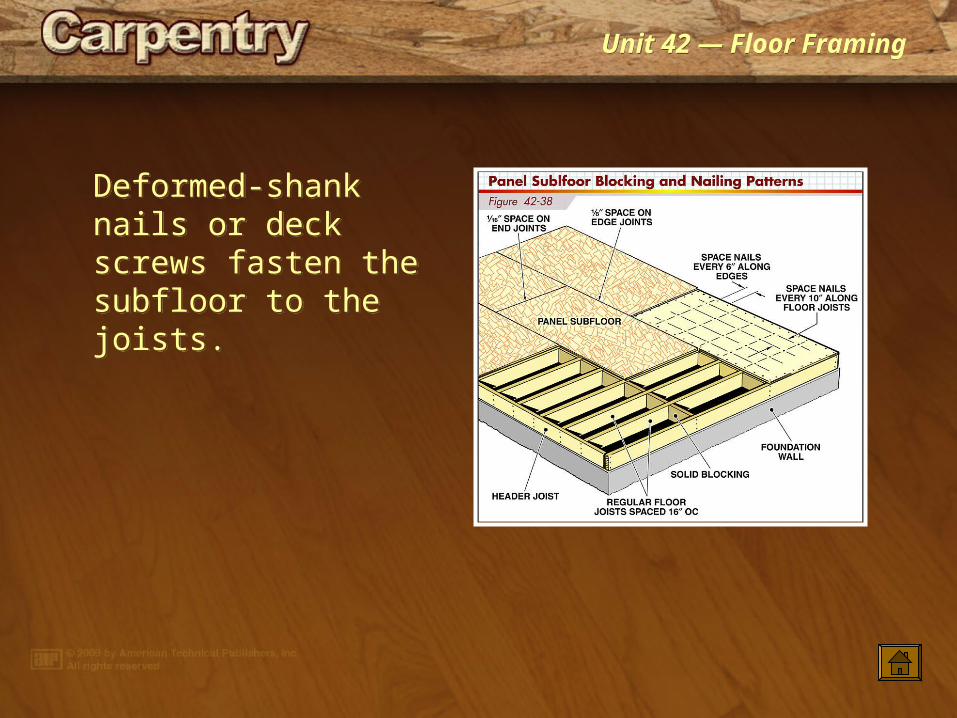
Deformed-shank nails or deck screws fasten the subfloor to the joists.
Deformed-shank nails or deck screws fasten the subfloor to the joists.
Unit 42 — Floor FramingUnit 42 — Floor Framing
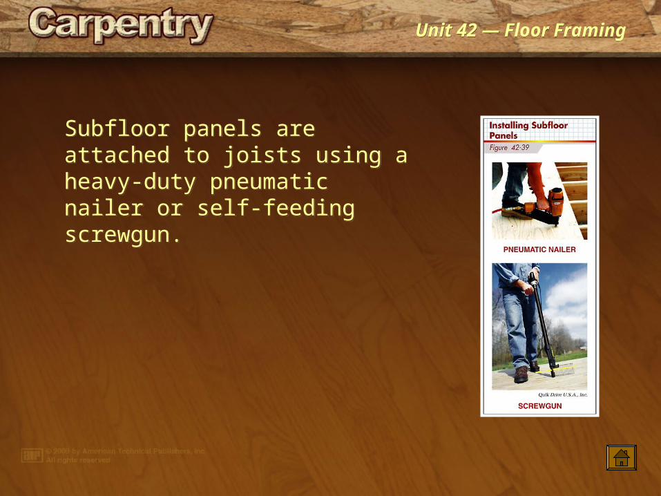
Subfloor panels are attached to joists using a heavy-duty pneumatic nailer or self-feeding screwgun.
Subfloor panels are attached to joists using a heavy-duty pneumatic nailer or self-feeding screwgun.

Unit 42 — Floor FramingUnit 42 — Floor Framing
Aligning the first row of panels with a chalk line 4′-0″ from the edge of the building ensures that the first row of panels will be perfectly straight even if the edge of the building is not straight. When placing the remaining panels, drive a few fasteners to secure the panels in place. Then, snap chalk lines across the panels in line with the joist centers below and complete nailing or screwing down the panels.
Aligning the first row of panels with a chalk line 4′-0″ from the edge of the building ensures that the first row of panels will be perfectly straight even if the edge of the building is not straight. When placing the remaining panels, drive a few fasteners to secure the panels in place. Then, snap chalk lines across the panels in line with the joist centers below and complete nailing or screwing down the panels.
Unit 42 — Floor FramingUnit 42 — Floor Framing
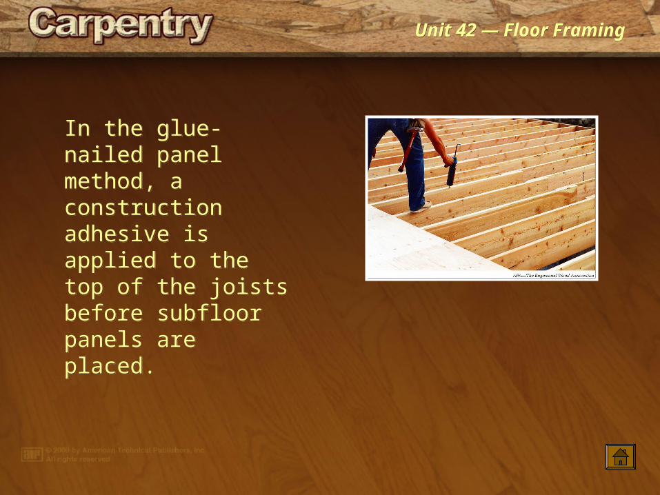
In the glue-nailed panel method, a construction adhesive is applied to the top of the joists before subfloor panels are placed.
In the glue-nailed panel method, a construction adhesive is applied to the top of the joists before subfloor panels are placed.

Unit 42 — Floor FramingUnit 42 — Floor Framing
In a post-and-beam subfloor, the floor unit receives its main support from beams rather than from floor joists.
In a post-and-beam subfloor, the floor unit receives its main support from beams rather than from floor joists.
Unit 42 — Floor FramingUnit 42 — Floor Framing
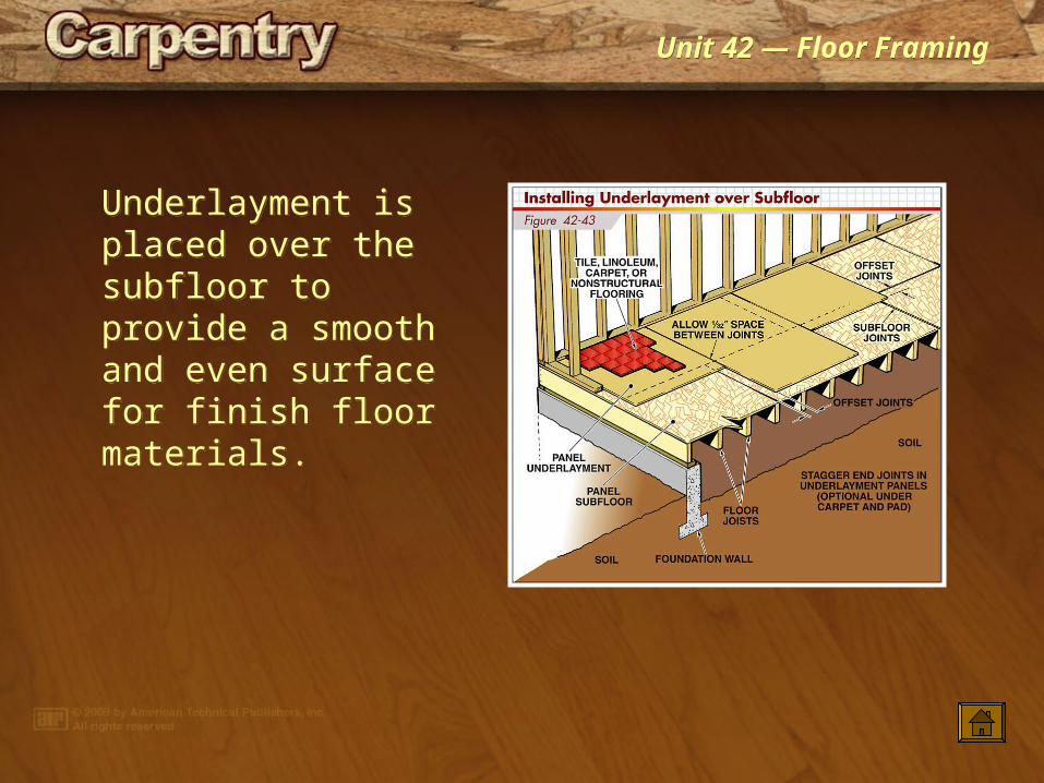
Underlayment is placed over the subfloor to provide a smooth and even surface for finish floor materials.
Underlayment is placed over the subfloor to provide a smooth and even surface for finish floor materials.
Unit 42 — Floor FramingUnit 42 — Floor Framing
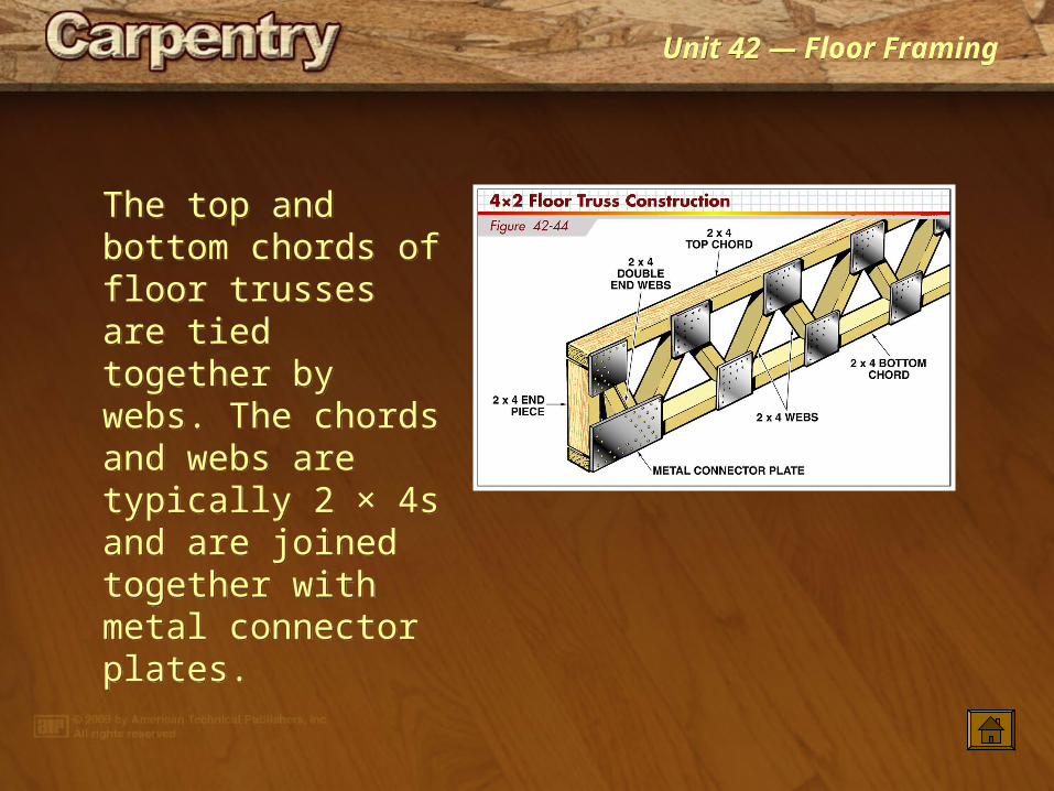
The top and bottom chords of floor trusses are tied together by webs. The chords and webs are typically 2 × 4s and are joined together with metal connector plates.
The top and bottom chords of floor trusses are tied together by webs. The chords and webs are typically 2 × 4s and are joined together with metal connector plates.
Unit 42 — Floor FramingUnit 42 — Floor Framing
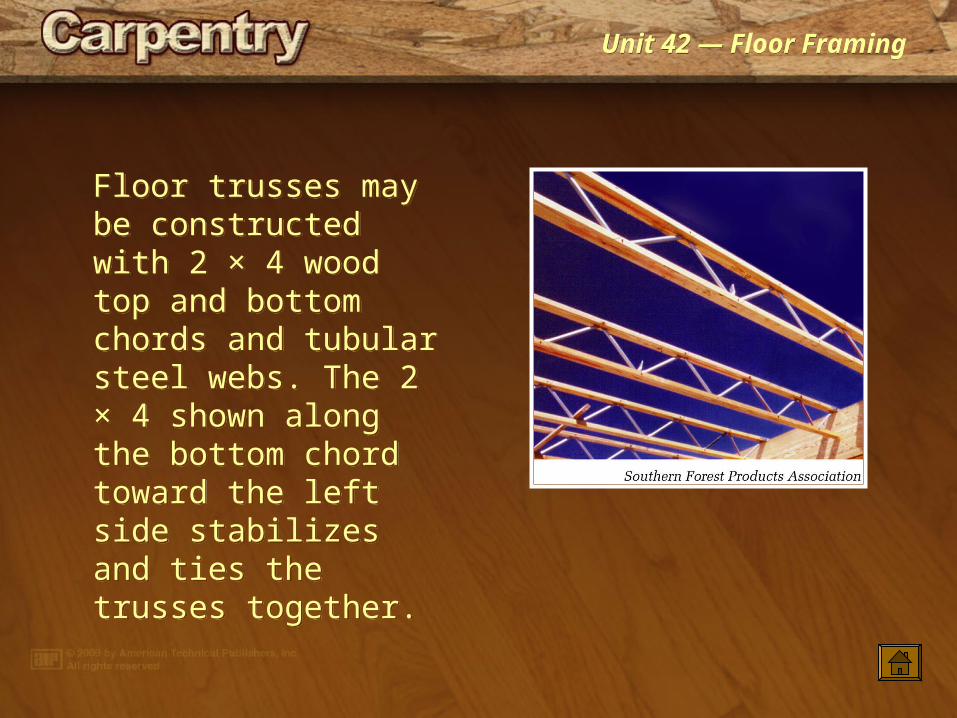
Floor trusses may be constructed with 2 × 4 wood top and bottom chords and tubular steel webs. The 2 × 4 shown along the bottom chord toward the left side stabilizes and ties the trusses together.
Floor trusses may be constructed with 2 × 4 wood top and bottom chords and tubular steel webs. The 2 × 4 shown along the bottom chord toward the left side stabilizes and ties the trusses together.
Unit 42 — Floor FramingUnit 42 — Floor Framing
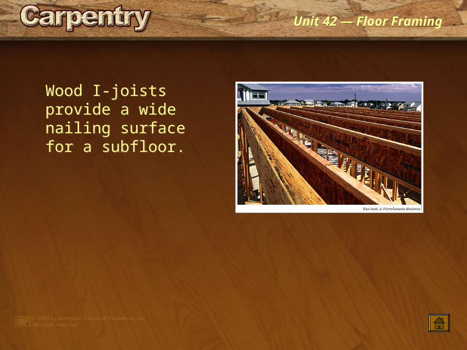
Wood I-joists provide a wide nailing surface for a subfloor.
Wood I-joists provide a wide nailing surface for a subfloor.
Unit 42 — Floor FramingUnit 42 — Floor Framing
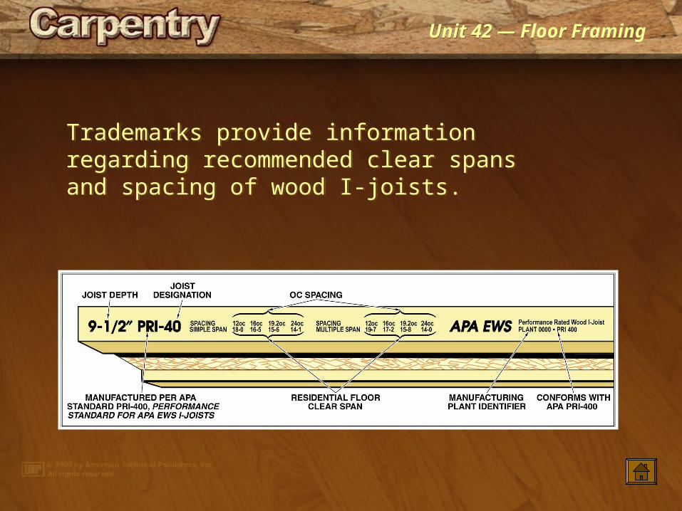
Trademarks provide information regarding recommended clear spans and spacing of wood I-joists.
Trademarks provide information regarding recommended clear spans and spacing of wood I-joists.
Unit 42 — Floor FramingUnit 42 — Floor Framing
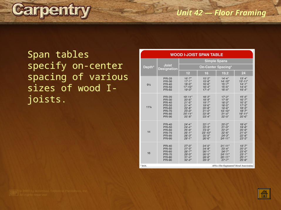
Span tables specify on-center spacing of various sizes of wood I-joists.
Span tables specify on-center spacing of various sizes of wood I-joists.
Unit 42 — Floor FramingUnit 42 — Floor Framing
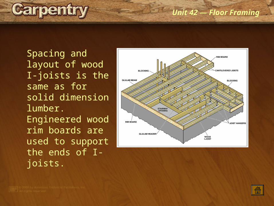
Spacing and layout of wood I-joists is the same as for solid dimension lumber. Engineered wood rim boards are used to support the ends of I-joists.
Spacing and layout of wood I-joists is the same as for solid dimension lumber. Engineered wood rim boards are used to support the ends of I-joists.
Unit 42 — Floor FramingUnit 42 — Floor Framing
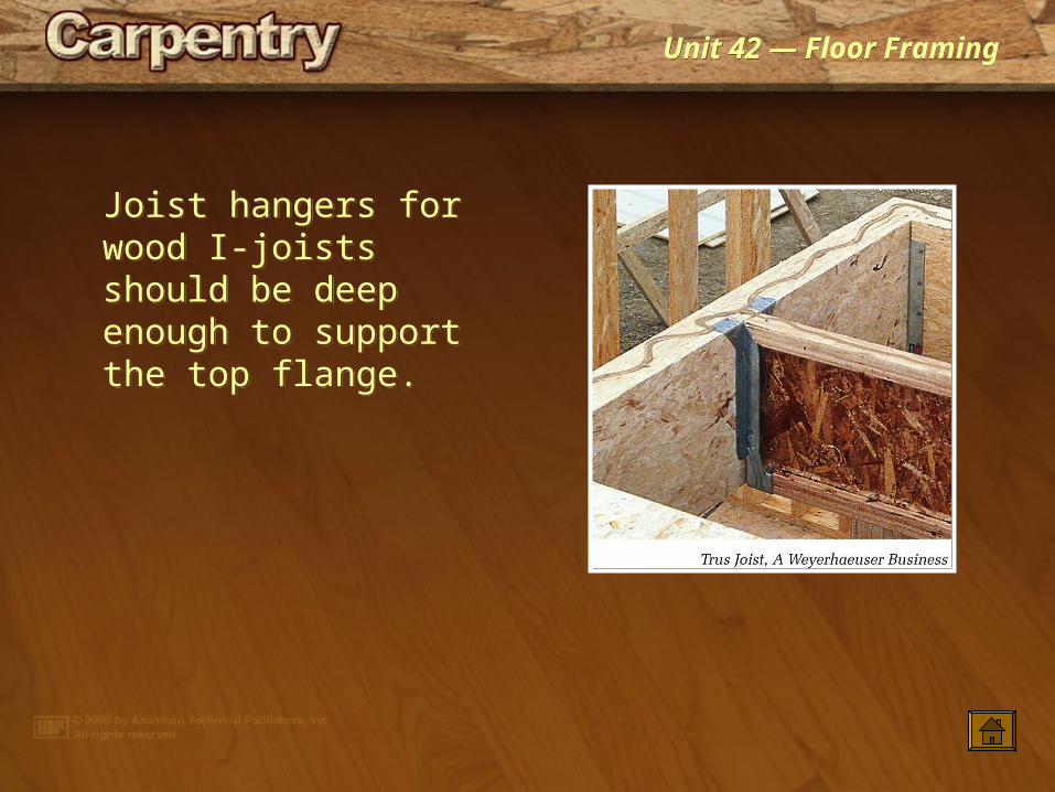
Joist hangers for wood I-joists should be deep enough to support the top flange.
Joist hangers for wood I-joists should be deep enough to support the top flange.

Unit 42 — Floor FramingUnit 42 — Floor Framing
Backer blocks provide a flat, flush surface for attachment of top-flange or face-mount joist hangers or other structural elements.
Backer blocks provide a flat, flush surface for attachment of top-flange or face-mount joist hangers or other structural elements.

Unit 42 — Floor FramingUnit 42 — Floor Framing
Web stiffeners reinforce I-joist webs. The direction of an applied load determines the location of the gap between the stiffener and top or bottom flange.
Web stiffeners reinforce I-joist webs. The direction of an applied load determines the location of the gap between the stiffener and top or bottom flange.

Unit 42 — Floor FramingUnit 42 — Floor Framing
Filler blocks permit a vertical load to be shared between two I-joists.
Filler blocks permit a vertical load to be shared between two I-joists.
Unit 42 — Floor FramingUnit 42 — Floor Framing
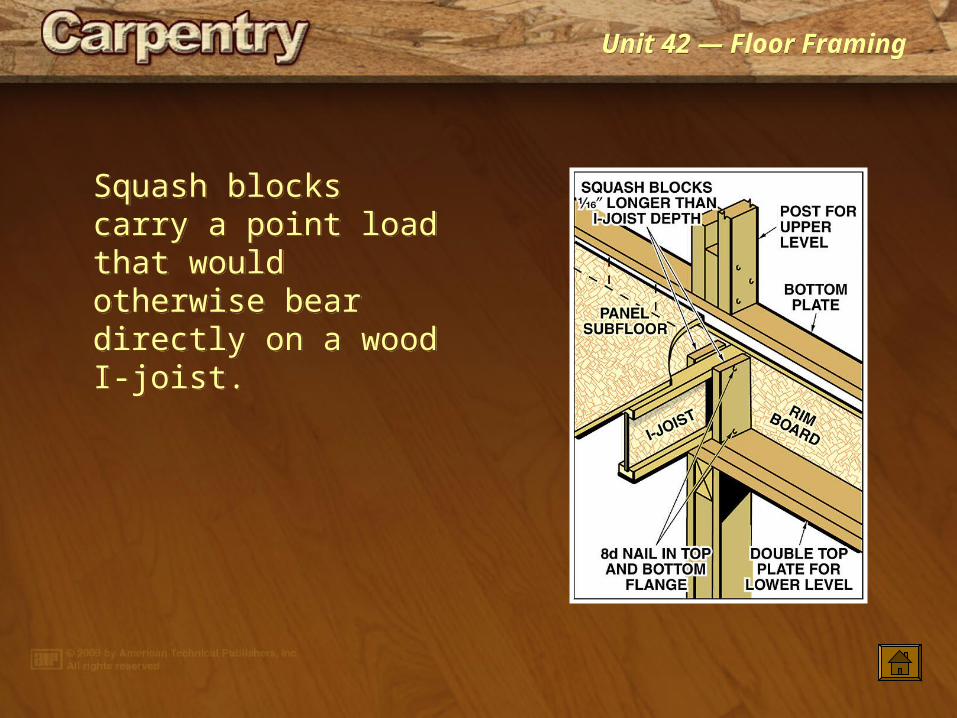
Squash blocks carry a point load that would otherwise bear directly on a wood I-joist.
Squash blocks carry a point load that would otherwise bear directly on a wood I-joist.

Unit 42 — Floor FramingUnit 42 — Floor Framing
Blocking provides lateral support for floor I-joists, transfers shear loads from walls above to floor or foundation below, and transfers vertical loads from the walls above to the floor or foundation below.
Blocking provides lateral support for floor I-joists, transfers shear loads from walls above to floor or foundation below, and transfers vertical loads from the walls above to the floor or foundation below.