power/ground isolation and control in facilities,...
TRANSCRIPT

1
Power/Ground Isolation and Control in Facilities, Systems,
and in System Boxes Bruce C. Gabrielson, PhD Security Engineering Services 5005 Bayside Road Chesapeake Beach, Maryland 20732 Introduction Ground isolation between power systems and communication systems at either the box or system level is the primary protective barrier between a secure and a non-secure environment. At the macro level, facilities which process Command, Control, Communications, and/or Intelligence information are usually required to provide some level of security protection, often including RED/BLACK (COMSEC) and TEMPEST protection, for classified data transfers. Typically, these facilities have been built to a variety of building codes that either directly dictate the grounding and bonding employed or indirectly restrict what can be done to enhance the facilities secure processing capabilities. At the system level, secure conducted emission isolation can not take place unless proper separation of the various system parts is maintained. This isolation at the system level is difficult to achieve unless the facility allows separate controlled power and ground systems to exist. At the micro level, various circuit nets also must maintain their own isolated power, signal return, and box ground control. Isolation at this level is also difficult to maintain, since often ground and power controls are circumvented due to radiated emissions and capacitive coupling paths not so readily identified as they would be at the macro level. Not only is isolated ground control for secure hardware a problem, but, as in the case of platforms, other EM related effects such as lightning, EMC, and EMP protection, plus their associated grounding and bonding requirements, can directly alter the ability of secure emission suppression techniques to function properly. In addition, emission problems that couple into the power system and then re-radiate through the extended antenna system these wires create is also a problem. As an example of interactive grounds at the facility level, the practices set forth in the National Electrical Code 1984 (NFPA 70)1 issued by the National Fire Protection Association control only the electrical fault protection ground network, and is not effective, nor does it address the elimination of ground loops in communication systems. Guidelines for protecting facilities that
1National Electrical Code 1984, NFPA 70-1984, National Fire Protection Association, Quincy, MA, 1983.
2
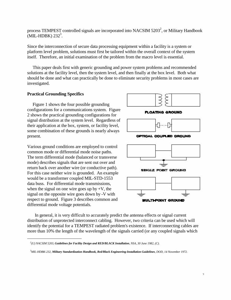
process TEMPEST controlled signals are incorporated into NACSIM 52032, or Military Handbook (MIL-HDBK) 2323. Since the interconnection of secure data processing equipment within a facility is a system or platform level problem, solutions must first be tailored within the overall context of the system itself. Therefore, an initial examination of the problem from the macro level is essential. This paper deals first with generic grounding and power system problems and recommended solutions at the facility level, then the system level, and then finally at the box level. Both what should be done and what can practically be done to eliminate security problems in most cases are investigated. Practical Grounding Specifics Figure 1 shows the four possible grounding configurations for a communications system. Figure 2 shows the practical grounding configurations for signal distribution at the system level. Regardless of their application at the box, system, or facility level, some combination of these grounds is nearly always present. Various ground conditions are employed to control common mode or differential mode noise paths. The term differential mode (balanced or transverse mode) describes signals that are sent out over and return back over another wire (or conductive path). For this case neither wire is grounded. An example would be a transformer coupled MIL-STD-1553 data buss. For differential mode transmissions, when the signal on one wire goes up by +V, the signal on the opposite wire goes down by -V with respect to ground. Figure 3 describes common and differential mode voltage potentials. In general, it is very difficult to accurately predict the antenna effects or signal current distribution of unprotected interconnect cabling. However, two criteria can be used which will identify the potential for a TEMPEST radiated problem's existence. If interconnecting cables are more than 10% the length of the wavelength of the signals carried (or any coupled signals which
2(U) NACSIM 5203, Guidelines for Facility Design and RED/BLACK Installation, NSA, 30 June 1982, (C).
3MIL-HDBK-232, Military Standardization Handbook, Red/Black Engineering-Installation Guidelines, DOD, 14 November 1972.
3
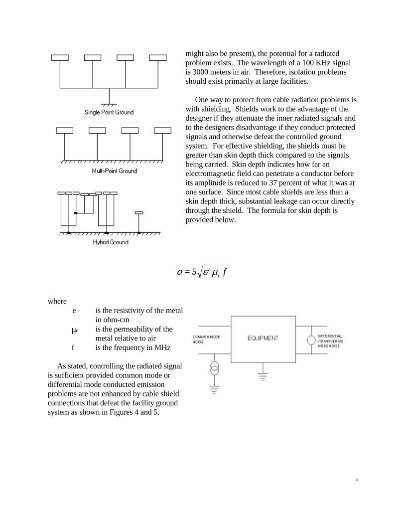
might also be present), the potential for a radiated problem exists. The wavelength of a 100 KHz signal is 3000 meters in air. Therefore, isolation problems should exist primarily at large facilities. One way to protect from cable radiation problems is with shielding. Shields work to the advantage of the designer if they attenuate the inner radiated signals and to the designers disadvantage if they conduct protected signals and otherwise defeat the controlled ground system. For effective shielding, the shields must be greater than skin depth thick compared to the signals being carried. Skin depth indicates how far an electromagnetic field can penetrate a conductor before its amplitude is reduced to 37 percent of what it was at one surface. Since most cable shields are less than a skin depth thick, substantial leakage can occur directly through the shield. The formula for skin depth is provided below.
where e is the resistivity of the metal
in ohm-cm µr is the permeability of the
metal relative to air f is the frequency in MHz As stated, controlling the radiated signal is sufficient provided common mode or differential mode conducted emission problems are not enhanced by cable shield connections that defeat the facility ground system as shown in Figures 4 and 5.
f/5 = rµεσ
4
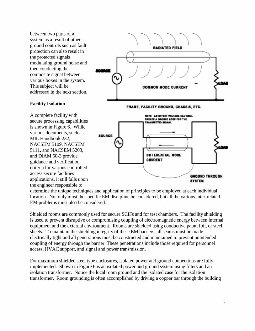
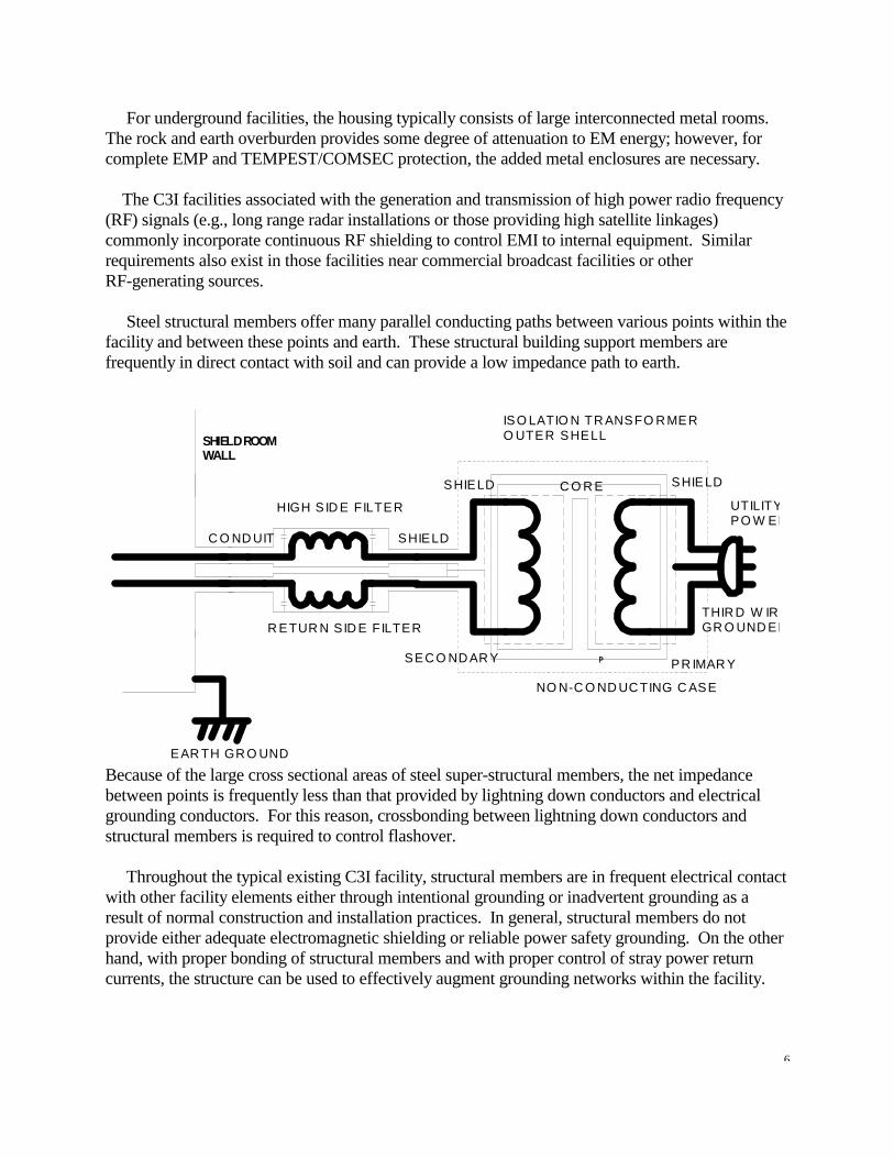
between two parts of a system as a result of other ground controls such as fault protection can also result in the protected signals modulating ground noise and then conducting the composite signal between various boxes in the system. This subject will be addressed in the next section. Facility Isolation A complete facility with secure processing capabilities is shown in Figure 6. While various documents, such as MIL Handbook 232, NACSEM 5109, NACSEM 5111, and NACSEM 5203, and DIAM 50-3 provide guidance and verification criteria for various controlled access secure facilities applications, it still falls upon the engineer responsible to determine the unique techniques and application of principles to be employed at each individual location. Not only must the specific EM discipline be considered, but all the various inter-related EM problems must also be considered. Shielded rooms are commonly used for secure SCIFs and for test chambers. The facility shielding is used to prevent disruptive or compromising coupling of electromagnetic energy between internal equipment and the external environment. Rooms are shielded using conductive paint, foil, or steel sheets. To maintain the shielding integrity of these EM barriers, all seams must be made electrically tight and all penetrations must be constructed and maintained to prevent unintended coupling of energy through the barrier. These penetrations include those required for personnel access, HVAC support, and signal and power transmission. For maximum shielded steel type enclosures, isolated power and ground connections are fully implemented. Shown in Figure 6 is an isolated power and ground system using filters and an isolation transformer. Notice the local room ground and the isolated case for the isolation transformer. Room grounding is often accomplished by driving a copper bar through the building

5
foundation and well into the ground beneath. Another method is to use a bar emerged in a well filled with salt water (salt pit ground). For safety reasons, isolation transformers usually have their case grounded. Ground isolation from the facility can then be achieved by using a plastic spacer in the conduit between the room and transformer. Additional information on Earth grounding is included later in this paper.
EQUI
PMEN
T RA
DIAT
ION
TEMP
EST
ZONE
(ETR
Z)
6
For underground facilities, the housing typically consists of large interconnected metal rooms. The rock and earth overburden provides some degree of attenuation to EM energy; however, for complete EMP and TEMPEST/COMSEC protection, the added metal enclosures are necessary. The C3I facilities associated with the generation and transmission of high power radio frequency (RF) signals (e.g., long range radar installations or those providing high satellite linkages) commonly incorporate continuous RF shielding to control EMI to internal equipment. Similar requirements also exist in those facilities near commercial broadcast facilities or other RF-generating sources. Steel structural members offer many parallel conducting paths between various points within the facility and between these points and earth. These structural building support members are frequently in direct contact with soil and can provide a low impedance path to earth.
Because of the large cross sectional areas of steel super-structural members, the net impedance between points is frequently less than that provided by lightning down conductors and electrical grounding conductors. For this reason, crossbonding between lightning down conductors and structural members is required to control flashover. Throughout the typical existing C3I facility, structural members are in frequent electrical contact with other facility elements either through intentional grounding or inadvertent grounding as a result of normal construction and installation practices. In general, structural members do not provide either adequate electromagnetic shielding or reliable power safety grounding. On the other hand, with proper bonding of structural members and with proper control of stray power return currents, the structure can be used to effectively augment grounding networks within the facility.
SHIELD ROOMWALL
ISO LATIO N TR ANSFO R MERO UTER SHELL
EAR TH GR O UND
NO N-C O ND UC TING C ASE
R ETUR N SID E FILTER
HIGH S ID E FILTER
SHIELDC O ND UIT
THIR D W IRGR O UND ED
UTILITYPO W ER
PR IMAR YSEC O ND AR Y
SHIELD C O R E SHIELD

7
Power System All facilities contain a power system and number of subsystems, each with unique requirements associated with some form of user activity or protection for the power system. The power system is a network of electrical equipment, conductors, and distribution panels located throughout the C3I facility. The purposes of this network are to: 1. Transform, as necessary, and route commercially supplied power into the facility; 2. Generate appropriate on-line electrical power as required, especially during the absence
of commercial power; 3. Switch between the two sources of power as required; 4. Condition the electrical power for the critical loads being served; 5. Provide uninterrupted electrical power for critical equipment 6. Distribute appropriate electrical power to the various equipment throughout the facility The US Army Corps of Engineers have identified and cataloged a number of subsystems supporting the facility and its ground requirements4. Identified subsystems include utilities, HVAC, Earth electrode, lightning protection, communications, computing and data processing control, signal security, and personnel support equipment. The problem associated with these various subsystems in secure facilities is their interactive effect on the specific protection control installed for emission security. The primary subsystems affecting the facility signal security subsystem are lightning protection, communications, computing and data processing, and control. The following information, partly extracted from the Corps of Engineers report, describe each subsystem as it relates to grounding control. Lightning Subsystem A lightning protection subsystem is frequently installed to protect the structure, personnel, and equipment from damage. The subsystem is a network of bonded air terminals and down conductors distributed over the exterior of the structure and then connected at many points to the earth electrode system.
4Denny, H.W., Shands, T.G., Woody, J.A. and McCormack, R.G., Integrated Grounding and Bonding Practices in Command, Control, Communications, and Intelligence Facilities, USA-CERL Technical Report M-89/01, October 1988.

8
Lightning down conductors provide preferential paths for the lightning energy to follow from the air terminals and roof conductors to earth. Since analytical tools and measurement methods are not available for determining in advance the path of least resistance for a lightning discharge, down conductors are routed to follow the straightest and shortest path from the air terminals to earth. The down conductors must terminate to the lowest available impedance contact with earth, which should be the earth electrode subsystem for the facility. Lightning surge arresters are placed on the primary and secondary terminals of transformers supplying commercial power to the facility. These surge arresters are typically the robust spark gap variety used by the power utilities to protect against lightning strokes to the transmission network. Additional arresters are placed at penetration points into the facility and at subsequent step-down transformers, switchgear, the UPS, and other vulnerable equipment locations. These added arresters include both lightning surge suppressors and the fast-acting semiconductor terminal protection devices (TPDs) necessary for EMI and EMP transient suppression. Complete lightning and EMP protection also requires that TPDs be placed on all exposed signal and control conductors at penetration points into EM-protected volumes. Communications Subsystem The communications subsystem is the network of electronic equipment, interfaces, and antennas whose elements are located both in, and around, the C3I facility. The purpose of the communications subsystem is to transfer information from one point to another. The information transfer may take place between points located within the facility or between different facilities. The electronic equipment making up the communications subsystem frequently include RF receivers and transmitters; audio, baseband, and RF amplifiers; data terminals and displays; telephones; modems; multiplexers; frequency converters; encryption devices; and other C-E (communication-electronic) equipment. Within the facility, the interfaces between equipment are generally hard-wired signal lines or waveguides. Signal penetrations into the facility include coaxial and waveguide for RF signals and, shielded, multi-conductor cables for telephone, data, and control signals. Fiber optic penetrations are being increasingly used for EMP-protected facilities. Between facilities, the information transfer is usually via land lines or RF transmission. The RF antennas are generally located on or near the facility. The various communication subelements include telephone, radio, local area data transfer, and high-speed data. The telephone subelements provide internal communications via hard-wired interfaces and intersite communications via land lines or microwave links. As a minimum, the telephone subsystem consists of the telephone instrument sets, cabling, and distribution frames. Larger facilities generally also have a PBX (Centrex) and/or automatic switching racks, intercom apparatus, and a telephone power plant. Radio transceiver equipment converts audio and baseband signals to an RF signal, radiates the RF signal to the receiving point, and then converts the RF signal back to the appropriate audio or

9
baseband signal. Since it has both low frequency and RF equipment interconnected within the same network, the operating frequencies of the radio subsystem cover an extremely wide range. The low frequency signal interfaces to and from the RF equipment may be either single-ended or balanced, twisted-pair lines. Depending on the frequency of operation, the RF signal interfaces may be either coaxial lines or waveguides. These various types of interfaces are co-mingled within the radio equipment. Another communication subsystem is that associated with high speed data transmission. This subsystem is used to transfer high-speed data signals between data processing equipment. The transmission paths employ both shielded twisted pair and coaxial cables. The equipment of the various communication elements is likely to be distributed throughout the facility and grounded at multiple points. The equipment cases, racks, and frames are grounded to the ac power ground, to raceways and conduit, and to structural members at numerous locations within the facility. In many facilities, a single point configuration for the signal reference ground is said to be implemented for telephone circuits and for data processing circuits. Actually, however, a single point ground configuration does not exist because of internal grounding of signal references to cabinets and enclosures with subsequent interconnections to power conduits and raceways and because of the use of unbalanced interfaces between the various pieces of equipment. Consequently, the effective signal reference ground for the communication subsystem in the typical C3I facility is a multipoint grounded system with numerous interconnections between signal references, equipment enclosures, raceways, conduit, and structural members. Computing and Data Processing Subsystem A distinguishing feature of the C3I facility is the presence of many digital processors ranging from microcomputers performing dedicated equipment and instrument control to large interconnected mainframes providing complex analyses, signal processing, and image displays. These processors typically interface with numerous I/O (input/output) devices including keyboards, monitors, disk drives, tape drives, remote terminals, data acquisition and control equipment, and other processors. The data processing subsystems are configured in various ways. These various configurations result in a myriad of different grounding connections being established. For example, stand-alone desktop computers obtain power from single ac outlets and thus establish only one electrical safety ground connection. Other small computing systems may be configured so that the processor and I/O devices share the same outlet, or perhaps the same branch circuit. In this configuration, the ground connection is effectively a single connection although more than one physical tie is made. Where I/O and other peripherals are separated by large distances from the processor, multiple connections to the facility ground network result.

10
Larger computing subsystems are generally characterized by having the processor in one place and the peripherals distributed throughout the facility. In this configuration, the peripherals are supplied from different ac outlets, off different branch circuits, or perhaps from different phases of the line. In some installations, remote terminals may even be in separate buildings and supplied from different transformer banks. Each remote device must have a safety ground at its location. Noise in interconnecting paths can be encountered from stray currents in the ground reference network. The most practical approach to solving these noise problems is not to strive to implement a "single point" ground connection for the main processor but rather to minimize the stray current in the ground reference system and use effective common mode suppression techniques and devices in data paths. Control Subsystems Typical C3I facilities have many control and security devices which gather information and then automatically respond to a given situation by alerting personnel or engaging equipment to correct it. These subsystems range in nature from pneumatic and mechanical to electrical, electronic analog or digital, or a combination of these. Numerous current sensors, intrusion detectors, trip relays, sound detectors, remote control locks, remote control doors, and alarms are typically included in the systems. Many of the control subsystems are self-contained and independent, as, for example, intrusion detectors that sound alarms. Often, however, they interact with other facility elements. For example, the heating, ventilation and air-conditioning subsystem contains an integral network of temperature and humidity sensors along with actuators that control the interior air. For fire protection, smoke detectors sound alarms and temperature sensors start halon purging of the affected area. The power subsystem incorporates electronically operated circuit breakers to close or open circuits and to keep particular breaker combinations from being opened or closed simultaneously. Control subsystems range from being entirely automated to completely manual. One example of automated controls is that which switches over from commercial power to engine/generator power upon loss of commercial power. The control elements can automatically start the engine/generators, bring them up to proper speed and voltage, and switch the appropriate breakers. On the other hand, the operator has the option of performing each of these functions separately using selected devices of the control system to monitor the progress. In terms of grounding, the large diversity of the control subsystem results in various grounding paths being established. Small control devices are typically grounded through the ac safety ground provided via the power outlet. The more automated and complex subsystems, however, resemble a computer net or a communication subsystem. For example, sensors communicate information from their locations (which may be very remote) to a central location. In many cases, processors monitor the sensors, determine if an abnormal situation exists, and provide appropriate commands to control

11
the necessary equipment. The processor may be the main facility computer. In such cases, the grounding network resembles that of both data processing and communications. Signal Security Subsystem Equipment that processes sensitive RED information may produce signals capable of unauthorized detection. RED is a term applied to wire lines, components, equipment, and systems that handle national security signals, and to areas in which national security signals occur. BLACK, on the other hand, is a term applied to wire lines, components, equipment, and systems that do not handle national security signals, and to areas in which no national security signals occur. To prevent security compromises of RED information, measures must be taken to reduce sensitive data signals to levels low enough to make detection impossible in areas accessible to unauthorized personnel. These measures include controlled grounding practices which in many cases are in conflict with other subsystem requirements. Typical isolation techniques are shown in Figure 8. The recommended approach to grounding a TEMPEST or RED/BLACK signal reference system is illustrated in Figure 9. Notice that all equipment cabinet grounds, RED signal grounds, and BLACK signal grounds are made with respect to the ground reference established inside the controlled access area (CAA). Both RED and BLACK cable shields are peripherally bonded to equipment cabinets at both ends. The low sides of BLACK data lines are connected to cable shields in the BLACK IDF (Intermediate Distribution Frame) and both are grounded to the reference plane. Notice that BLACK cables should exit the controlled area via filtered couplings through the CAA boundary.

12
Figure 8 - Typical Recommended RED/BLACK Signal and Power Reference Subsystem

13
Figure 9 shows an actual application for a RED/BLACK signal reference system. Notice here that nonconductive spacers are used to break current paths through the conductive conduit. Figure 10 depicts the grounding approach recommended for AC power distribution in secure facilities. Note that both the neutral and phase conductors are filtered. As previously mentioned, the neutral is grounded only at the service disconnect. The cases of all subsequent distribution panels, filter enclosures, technical power panels, and equipment are all interconnected with the deliberately installed grounding conductor. Note that the equipment cases are connected to the BLACK signal reference system which is grounded to the reference plane. There has been significant interest in eliminating powerline filters for facilities which draw an average power of more than 100 KVA. While this might be acceptable for equipment which operates at low data rates and in facilities which have placed their power cabling inside metal conduit, there is a considerable risk that high frequency classified information could very easily escape the protected area through an extended powerline antenna system. This condition exists when the building power system acts like an antenna, and re-radiates any coupled signals which exist at frequencies well above the powerline frequency. Such signals do occur in high resolution graphics workstations. Grounding Design Procedures for Existing Facilities While conducted emission control of the power and ground distribution system may be straight forward to implement in a new facility, this situation seldom exists in real world situations. In by far the majority of cases, the facility already exists, and some measure of control must be implemented to protect a planned secure system installation. Since achieving complete protection is unlikely, the next best approach is to apply "after the fact" fixes in as many areas as can be easily accommodated. For existing facilities, the grounding principles pertaining to signal security can best be addressed by following some basic rules. By attempting to follow these rules as far as practical, a solid security control program can be achieved. Therefore, to install the described TEMPEST grounding and bonding networks in an existing facility, it is recommended by the Corps of Engineers5 that the following steps be taken: 1. Conduct a detailed survey of ALL grounding networks and bonds in the facility. All
networks including power safety grounds, connections to the earth electrode subsystem to include water pipes and lightning protection ground rods, utility pipe interconnections, electronic equipment grounds to include the interconnections with the power safety grounding subsystem, tower grounds, and building and structural interconnections with the grounding networks must be accurately defined. Update all drawings, paying specific
5ibid, Denny et al.

14
attention to including all electronic equipment grounding interconnections with the power safety and lightning grounding networks.
2. Carefully examine all accessible bonds for looseness and evidence of corrosion. Clean
and tighten all deficient bonds. Measure a representative sampling of bonds using the procedures of MIL-HDBK-419A, Volume II. 3. Also using the recommended procedures of Volume II of MIL-HDBK-419A, measure the stray ac current levels on accessible conductors of the fault protection subsystem and on electronic equipment signal ground conductors. Any stray power current readings in excess of 1 ampere should be thoroughly checked out to find the cause. Currents in excess of 5 amperes are likely to be the result of electrical wiring errors either in the ac supply system or inside electronic equipment. All such errors should be located and corrected immediately.
Only the Collector & Emitterof the Opto-isolator are Carried
All lines are MIL-188-144 balanced
All cables are foil shielded pairs withan overall shielded conduit
Individual shields are carried through thesystem on one pin with one connection atthe Red/Black interface
Cable shields are broken with spacers at X.
BEA
Located inBEA REA
SYSTEM
KG R EDPATC H
R EDPATC H
BLAC KPATC H
BLAC K/R EDO pto-Isolator
R EDTerm inal
Located inR EA

15
4. Compare the updated as-built grounding drawings with the recommendations contained
in this document. 5. Evaluate cost and operational impacts of upgrading the facility grounding networks and
bond networks as recommended, including the installation of an EESS as described in MIL-HDBK 232A.
6. Prepare plans and schedules to implement the modifications necessary to achieve an
integrated grounding network for the facility. 7. Define and implement a routine schedule for inspection and maintenance of bonds. Set
up a maintenance log or file and keep it updated.
Technical PowerPanel
DistributionPanel
Main ServiceDisconnect
Equipment
Mount all filters regardlessof phase in a single box throughthe stud. Braze both sides.
Earth ElectrodeSystem
NeutralHotGreen Safety Ground
Neutral Bus Ungrounded
Neutral Bus Grounded
Mounting Plate*
* Snap to Filter
Earth ElectrodeSystem
NOTE: WHEN THE USE OF NEUTRAL FILTERS INTRODUCESOPERATIONAL PROBLEMS, THE NEED FOR SUCH USE SHOULDBE VERIFIED BY TEMPEST TESTING.
THE GREEN WIRE CONDUCTOR IS THE SAME AWG AS THENEUTRAL FROM THE FILTER.

16
8. Inspect all impacted grounding networks and electrical supply circuits for unauthorized
changes and wiring errors following any new installation or rework. 9. Carefully document all additions and changes to grounding networks. Update all
affected drawings. Interactive Control to Address All Protection Subsystems Grounding and bonding principles for secure communications, computing, and data processing subsystems are summarized in tables on the following pages for each EM discipline. An attempt has been made here, again by the Corps of Engineers6, to reduce or minimize interactive problems within the various protection techniques.
6ibid, Denny et al.
TEMPEST Signal Reference Subsystem
NOTE: Green wires not shown GROUND PLANE
RED Equipment
Conduit
CRYPTO
RED Signal Ref. RED/BLACKInterface BLACK Signal Ref.
FilteredPenetration
BLACK IDF
BLACK Equip.
CAARED IDF

17
Signal Security
A signal reference subsystem shall be established inside the Controlled Access Area (CAA). This ground reference subsystem will consist of multiple interconnections between equipment cabinets, frames and racks; between conduit, raceway and wire-way; between these communication subsystem members and structure; and shall incorporate raised floors into the reference subsystem. Terminate shields of all cables in the CAA to the signal reference subsystem within the CAA's.
Power Safety
Power Safety Green wire grounding conductor must be run with power conductors and connected to equipment cases.
Lightning
The ground terminal of surge arresters and TPD's shall be bonded to the mounting enclosure with minimum length conductors. The enclosure shall be mounted directly to the tower structure or will be bonded with a minimum length, flat conductor. The ground lugs of terminal protection devices shall be bonded to distribution frame or junction box where mounted. The distribution frame or junction box must be grounded to the nearest structural frame member and, by extension, to the lightning down conductor. Penetrating waveguides and the shields of signal lines and data lines shall be bonded to the entrance panel, or to the facility ground with a minimum length conductor. Signal cable shields and waveguides shall be bonded to antenna tower structural members at the point of departure from the tower.

18
Facility Grounding Applications The basic concept of facility "grounding" is essentially the same for secure facilities with control zones as it is for all facilities, except that any electrical connection between interior and exterior components of the system for secure facilities must not result in inadvertent, compromising, control zone (CZ) penetrations. This applies whether or not the control space includes a shielded enclosure, with the understanding that there are unique features for shielded enclosures, including grounding and the design of intentional penetrations. Ground Conductor Impedance at Low Frequency At low frequencies, such as at 60 Hz, a single conductor used as a safety wire (per the National Electric Code) and a zero-volt reference generally poses no problem when configured into a "single-point" grounding system. The single-point ground is usually located at the power service entrance, or at the grounded transformer secondary neutral for a separately derived system. In this case the earth ground electrode system is comprised of a ground stake, ground ring, cold water pipe, etc. Ground Conductor Impedance at High Frequency At high frequencies, a single safety ground conductor becomes resonant with the resonant frequencies determined by the distributed inductance and capacitance, which is a function of conductor length. The resonance effects result in frequency-dependent ground impedance(s), which
EMC
A Signal Reference Subsystem shall be established. This ground reference subsystem will consist of multiple interconnections between equipment cabinets frames, and racks; between conduit, raceway and wireway; between these communication subsystem members and structure; and shall incorporate raised floors into the reference subsystem. Where space and accessibility exist, a wire mesh grid may be installed at floor level or overhead to supplement the above cabling network. Equipment enclosures and racks should be bonded to this wire mesh. The mesh should be bonded to structure at each point where structural members are accessible . Both ends of shielded cable shall be terminated to case or enclosure. Continuous peripheral bonding of the shield is best. Filters and TPD's installed for noise suppression and transient protection must be directly grounded to the enclosures of the protected equipment. TPD's installed in distribution frames and junction boxes must be terminated directly to the ground bus or to the mounting enclosure. The ground bus and the mounting enclosure must be bonded to the fault protection subsystem with minimum length conductors.

19
ANALO G
TR ANC IEVER
D IGITAL
Analog Ground
+15 volts
Pow erSupply
+ 5 volts
AnalogGroundLoop
D igital Ground
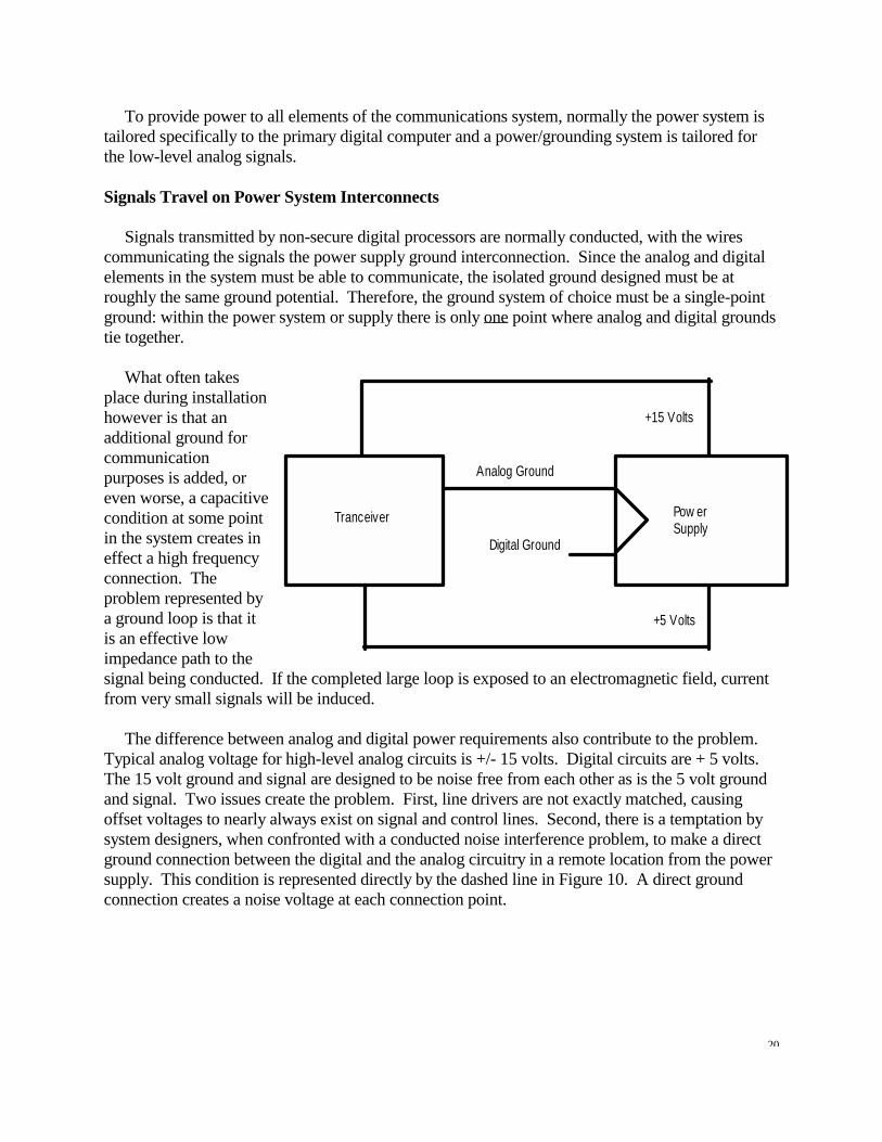
can have values of several hundred ohms or higher at certain frequencies. This often is a serious departure from the ideal (or desired) ground conductor impedance of zero ohms. For high frequencies, the single-point grounding concept is meaningless when the ground conductor length is a significant fraction of a wavelength. In this case it becomes necessary to resort to a multipoint ground reference (approximately equipotential) via low impedance ground planes or ground grids for a zero volt signal reference. Good facility engineering also assures that (1) safety requirements are met, (2) undesirable ground loops are avoided, and (3) no inadvertent security penetrations result through fortuitous means via the ground system. As mentioned earlier, when the source emission contains high frequency components, traditional control techniques (such as powerline filtering) are nearly always required. Communication Center System Ground Loops Ground based communications centers, especially those with telemetry links to satellite systems, use high speed central processing computers and other digital processing equipment to manipulate data. The fast transition waveforms create signals that can conduct or re-radiate to transmission wires, causing severe security issues. The problem is normally the existence of a single power system and ground system supplying not only the Red processing center, but also the COMSEC device and transmitter to the outside world. Figure 11 shows a typical transmission system with analog and digital circuitry powered from a single point ground power supply. Note that the direct connection of the analog and digital ground (dotted line) creates a ground loop and conducted path for the digital signals. The digital computer is not especially sensitive, and small voltage changes do not effect its data transmission between digital interfaces. However, coexisting within this noisy environment are critical analog and RF circuitry that is sensitive to even the slightest voltage change. Not only is there a basic operational problem of operating analog circuits requiring a low-noise environment, but securing analog circuits is extremely complicated. Protected data transmission must be smooth and continuous in order to preserve the integrity of a continuously varying signal.
20
Analog Ground
Digital Ground
Pow erSupply
+5 Volts
+15 Volts
Tranceiver
To provide power to all elements of the communications system, normally the power system is tailored specifically to the primary digital computer and a power/grounding system is tailored for the low-level analog signals. Signals Travel on Power System Interconnects Signals transmitted by non-secure digital processors are normally conducted, with the wires communicating the signals the power supply ground interconnection. Since the analog and digital elements in the system must be able to communicate, the isolated ground designed must be at roughly the same ground potential. Therefore, the ground system of choice must be a single-point ground: within the power system or supply there is only one point where analog and digital grounds tie together. What often takes place during installation however is that an additional ground for communication purposes is added, or even worse, a capacitive condition at some point in the system creates in effect a high frequency connection. The problem represented by a ground loop is that it is an effective low impedance path to the signal being conducted. If the completed large loop is exposed to an electromagnetic field, current from very small signals will be induced. The difference between analog and digital power requirements also contribute to the problem. Typical analog voltage for high-level analog circuits is +/- 15 volts. Digital circuits are + 5 volts. The 15 volt ground and signal are designed to be noise free from each other as is the 5 volt ground and signal. Two issues create the problem. First, line drivers are not exactly matched, causing offset voltages to nearly always exist on signal and control lines. Second, there is a temptation by system designers, when confronted with a conducted noise interference problem, to make a direct ground connection between the digital and the analog circuitry in a remote location from the power supply. This condition is represented directly by the dashed line in Figure 10. A direct ground connection creates a noise voltage at each connection point.

21
Bypass Capac itor
+15 Volts
+5 Volts
PowerSupply
Bypass Capac itor
Transciever
Digi tal Ground
Analog
The Transceiver is a Data Converter The transceiver converts the digital (or analog) signal to an analog RF output. All transceivers (or all data converters) normally have a common problem, they have analog circuits on one side and digital circuits on the other. Since the transceiver receives and generates both 5 volt and 15 volt signals, it must be able to support both ground systems. Ideally, an isolated supply and separate ground would be built into the converter to handle both grounds and thereby prevent a ground loop. However, in practice this is generally not the case. If the system is working off a single-point ground in its power supply, a single ground pin handling both analog and digital currents results in common impedance signal coupling. The condition is shown in Figure 12. Notice that powering the transceiver using only the digital ground places considerable faith on the bypass capacitors to reduce the digital signal coupling. This is the common approach used to protect against coupling.
Powering the transceiver with only the analog ground, as shown in Figure 13, can create a noise barrier between the digital processor and the output of the transceiver. In this case the +5 volt digital supply would require bypassing on the analog supply. However, a much more serious problem would be created since the digital signals must reference with the digital ground, and there is considerable noise current from the processors in the system that would flow if a ground loop was created. If this created noise barrier is high enough, transmission errors between equipment will be created. The common solution to all these problems usually involves the use of dc to dc converters, each with isolated outputs, and all referenced to the central power supply system. AC power is routed on separate lines to the transceiver and the Red and Black areas of the facility, with isolation transformers and powerline filters installed between the main power feed and each section of the
22
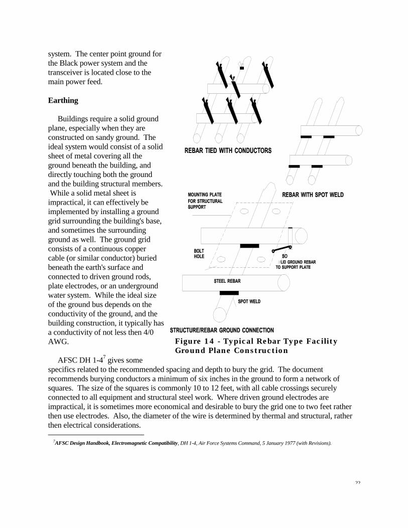
system. The center point ground for the Black power system and the transceiver is located close to the main power feed. Earthing Buildings require a solid ground plane, especially when they are constructed on sandy ground. The ideal system would consist of a solid sheet of metal covering all the ground beneath the building, and directly touching both the ground and the building structural members. While a solid metal sheet is impractical, it can effectively be implemented by installing a ground grid surrounding the building's base, and sometimes the surrounding ground as well. The ground grid consists of a continuous copper cable (or similar conductor) buried beneath the earth's surface and connected to driven ground rods, plate electrodes, or an underground water system. While the ideal size of the ground bus depends on the conductivity of the ground, and the building construction, it typically has a conductivity of not less then 4/0 AWG. AFSC DH 1-47 gives some specifics related to the recommended spacing and depth to bury the grid. The document recommends burying conductors a minimum of six inches in the ground to form a network of squares. The size of the squares is commonly 10 to 12 feet, with all cable crossings securely connected to all equipment and structural steel work. Where driven ground electrodes are impractical, it is sometimes more economical and desirable to bury the grid one to two feet rather then use electrodes. Also, the diameter of the wire is determined by thermal and structural, rather then electrical considerations. 7AFSC Design Handbook, Electromagnetic Compatibility, DH 1-4, Air Force Systems Command, 5 January 1977 (with Revisions).
Figure 14 - Typical Rebar Type Facility Ground Plane Construction

23
While a specially prepared earth grid system might provide the lowest inductance ground, there is often a more practical approach that fits in well with standard construction techniques. A commonly used technique is to spot weld together or tie with copper wire in the form of a grid the steel rebar placed in the foundation before the concrete is poured such as shown in Figure 14. Next, insure that this grid structure is conductivity connected to each metal structural member through the concrete foundation, preferably using bolts. The resultant ground plane provides a uniform low impedance multi-point ground plane for the building power system, and will effectively eliminate extended antenna power systems. RED/BLACK processing facilities specify an Earth electrode subsystem (EESS) be used. The EESS is tasked with providing the low impedance path for shunting earth referenced disturbances. The EESS is essentially the ground grid system previously described. However, the EESS must be connected through a low impedance path to a single facility entrance plate in secure processing facilities. All conductors entering or leaving the facility pass through the entrance plate, making it the ideal point for decoupling compromising emanations. Since it is used as the decoupling point, the plate is normally located near the secure processing area. MIL-HDBK 232A provides specific requirements for an EESS. The EESS described could be implemented into an existing facility. According to 232A, the EESS in this case consists of a bare No. 1/0 AWG 7-strand copper wire buried a minimum of 1.5 feet (.045 m) below the Earth surface and not less than 2 feet (.06 m) nor more than 6 feet (1.8 m) from the building drip line. Copper-clad steel ground rods measuring 0.75 inch (19 mm) by 10 feet (3 m) are to be installed not more than 20 feet (6 m) apart. The rods are bonded to the copper wire by welding or brazing. The EESS is a closed loop that surrounds the facility. The design objective for the ground resistance of the EESS should not exceed 10 ohms.
EARTH
AC InletAC ProtectiveGround
GROUNDING STRAPS WELDEDBETWEEN BODY AND FRAME
24
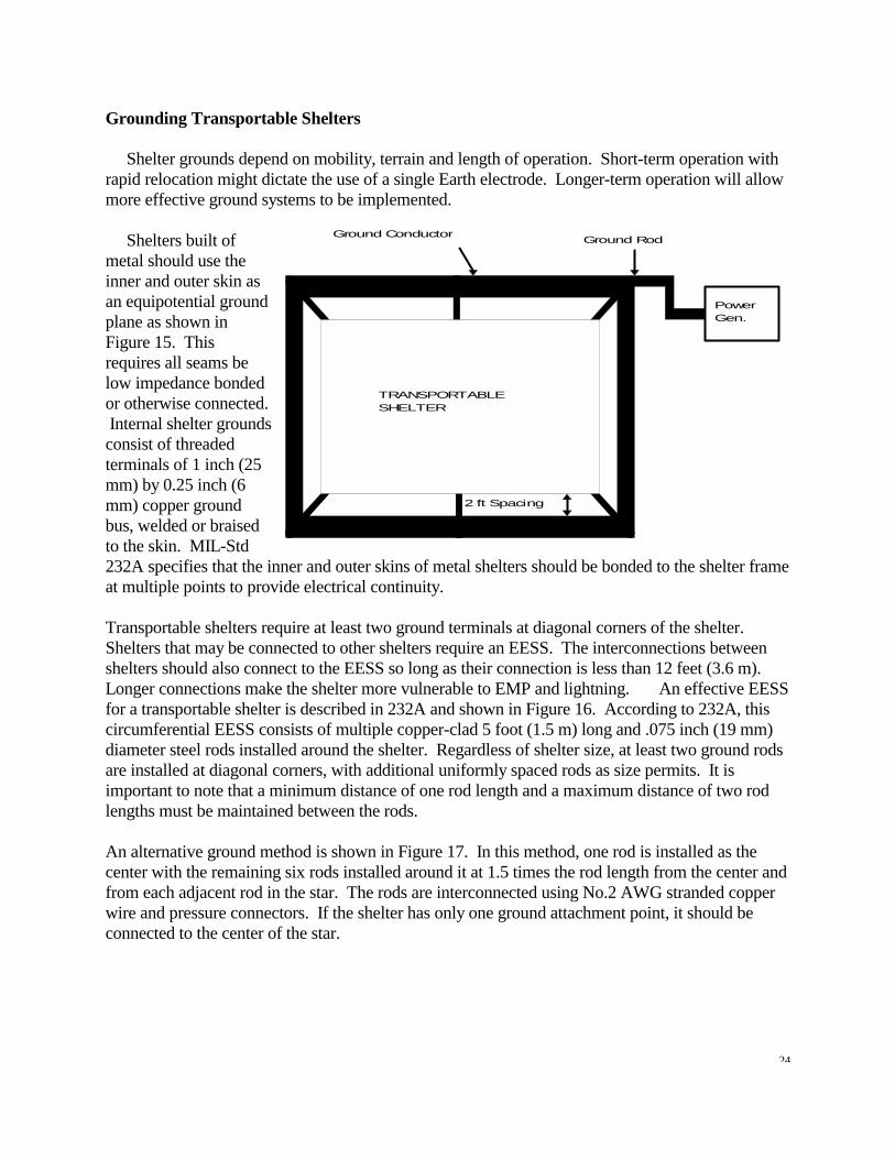
Grounding Transportable Shelters Shelter grounds depend on mobility, terrain and length of operation. Short-term operation with rapid relocation might dictate the use of a single Earth electrode. Longer-term operation will allow more effective ground systems to be implemented. Shelters built of metal should use the inner and outer skin as an equipotential ground plane as shown in Figure 15. This requires all seams be low impedance bonded or otherwise connected. Internal shelter grounds consist of threaded terminals of 1 inch (25 mm) by 0.25 inch (6 mm) copper ground bus, welded or braised to the skin. MIL-Std 232A specifies that the inner and outer skins of metal shelters should be bonded to the shelter frame at multiple points to provide electrical continuity. Transportable shelters require at least two ground terminals at diagonal corners of the shelter. Shelters that may be connected to other shelters require an EESS. The interconnections between shelters should also connect to the EESS so long as their connection is less than 12 feet (3.6 m). Longer connections make the shelter more vulnerable to EMP and lightning. An effective EESS for a transportable shelter is described in 232A and shown in Figure 16. According to 232A, this circumferential EESS consists of multiple copper-clad 5 foot (1.5 m) long and .075 inch (19 mm) diameter steel rods installed around the shelter. Regardless of shelter size, at least two ground rods are installed at diagonal corners, with additional uniformly spaced rods as size permits. It is important to note that a minimum distance of one rod length and a maximum distance of two rod lengths must be maintained between the rods. An alternative ground method is shown in Figure 17. In this method, one rod is installed as the center with the remaining six rods installed around it at 1.5 times the rod length from the center and from each adjacent rod in the star. The rods are interconnected using No.2 AWG stranded copper wire and pressure connectors. If the shelter has only one ground attachment point, it should be connected to the center of the star.
Ground Conductor Ground Rod
TRANSPORTABLESHELTER
PowerGen.
2 ft Spacing

25
When the shelter is located in sand, on granite, or on any other similar foundation, conventional grounding may not be practical. Under these conditions, a copper mesh screen of not less than 10 feet square (3 m sq.) is used for an EESS. Over hard surfaces, the screen (shown in Figure 18) is laid on the ground and holes are either dug or drilled at about 2.5 feet (.75 m) spacing around the perimeter. Fluted ground pins (shown in Figure 19) are then driven into the holes and attached to the screen with pressure connectors. The screen is then covered with one inch of sand and treated with a thin layer of magnesium sulphate (salt). In sandy desert regions, the pins are not used but instead the screen is buried approximately 6 inches (150 mm) under the sand. Isolated System Grounding at the Box Level Systems are made up of individual boxes interconnected in a variety of ways. Since interactive grounding is a common problem, isolated box level grounding approaches are available to deal with system level needs. Figure 20 describes a single point ground system for a typical box located within a controlled and isolated system. Two important points can be noted from the figure. First, the AC power input is isolated from the system ground. Achieving an isolated input may require the use of an isolation transformer prior to the power supply input to the box. Notice the output ground is carried to only one point inside the box and also to the power system ground. The output drivers and receivers are in turn ground isolated from the
GROUNDRODS
GROUNDCONDUCTOR
10 ft
10 ft
2 1/2 ft

26
box control logic, with an isolation resistor used for referencing the driver/receiver circuitry. Since power for other boxes in the system can be derived in this case from a central power supply, and since all other box power grounds are referenced to the same point, isolation between each interface can be effectively achieved. Now consider the more commonly found ground system shown in Figure 21. This ground features a hybrid approach where both single point grounding for the system and multi-point grounding within the box is utilized. Notice here that the output driver and receiver circuits are transformer decoupled from the control logic, and the ground also has a resistor decoupling the grounds. Also, for this case, the power supply secondary is floated with the input power green wire attached to chassis.
7/8 in
12 in
2 in
InputSignals Input
SignalProcessor
InputGround
ControlLogic
LogicGround
Logic P ackageGround
Filter Ground
Sys temGround
C onditionedS ignals
O utputS ignals
O utputD rivers &R eceivers
R ET.
O utputGroundR ET.
D C /D C Logic S upply
D C O utputPow er
AC
Pow er F ilters &Input Trans form er
Chassis

27
Summary The objective of this survey is to compress several grounding techniques, guidelines, and relevant security information into a comprehensive report on grounding in facilities and systems that handle secure information. For existing facilities, two conclusions are obvious. First, these facilities have differences due to their construction under prevailing concepts of signal grounding existing at the time. Second, establishing complete control of the ground and power system in an existing facility is difficult and should not be undertaken without considerable study. As a general recommendation, it is best to remember that signal grounding and power grounding are inseparable and should be jointly designed, installed, and maintained as an overall facility element rather than as individual subsystems.

28
The common solution to all these problems usually involves the use of DC-to-DC converters, each with isolated outputs, and all referenced to the central power supply system. AC power is routed on separate lines to the transceiver and the Red and Black areas of the facility, with isolation transformers and powerline filters installed between the main power feed and each section of the system. The center point ground for the Black power system and the transceiver is located close to the main power feed.