powered ankle-foot prosthesis for the improvement of...
TRANSCRIPT

Powered Ankle-Foot Prosthesis for the Improvement of AmputeeAmbulation
Samuel K. Au, Hugh Herr, Jeff Weber, and Ernesto C. Martinez-Villalpando
Abstract—This paper presents the mechanical design, controlscheme, and clinical evaluation of a novel, motorized ankle-footprosthesis, called MIT Powered Ankle-Foot Prosthesis. Unlike aconventional passive-elastic ankle-foot prosthesis, this prosthesiscan provide active mechanical power during the stance periodof walking. The basic architecture of the prosthesis is a unidi-rectional spring, configured in parallel with a force-controllableactuator with series elasticity. With this architecture, the ankle-foot prosthesis matches the size and weight of the human ankle,and is also capable of delivering high mechanical power andtorque observed in normal human walking. We also propose abiomimetic control scheme that allows the prosthesis to mimicthe normal human ankle behavior during walking.
To evaluate the performance of the prosthesis, we measuredthe rate of oxygen consumption of three unilateral transtibialamputees walking at self-selected speeds to estimate the metabolicwalking economy. We find that the powered prosthesis improvesamputee metabolic economy from 7% to 20% compared to theconventional passive-elastic prostheses (Flex-Foot Ceterus andFreedom Innovations Sierra), even though the powered systemis twofold heavier than the conventional devices. This resulthighlights the benefit of performing net positive work at the anklejoint to amputee ambulation and also suggests a new directionfor further advancement of an ankle-foot prosthesis.
I. INTRODUCTION
The human ankle provides a significant amount of netpositive work over the stance period of walking, especiallyat moderate to fast walking speeds [1]-[3]. On the contrary,commercially available ankle-foot prostheses are completelypassive during stance, and consequently, they cannot providenet positive work. These prostheses typically comprise elasticbumper springs or carbon composite leaf springs that storeand release energy during stance, e.g. the Flex-Foot [4].Clinical studies indicate that transtibial amputees using theseconventional passive prostheses experience many problemsduring locomotion, including non-symmetric gait patterns,slower self-selected walking speeds, and higher gait metabolicrates as compared to intact individuals [5][6][7]. Researchersbelieve [2][3][5] that the inability of conventional passive
This work was performed in the Biomechatronics Group at the MITMedia Lab and was supported in part by the U.S Department of Veteran’sAdministration under Grant V650P-3945.
S. Au is with the Department of Mechanical Engineering and the MITMedia Lab, Massachusetts Institute of Technology, Cambridge, MA, 02139USA (corresponding author phone: 617-324-1701; e-mail: [email protected].)
H. Herr is with the MIT Media Lab and the Harvard-MIT Division of HealthSciences and Technology, Massachusetts Institute of Technology, Cambridge,MA 02139 USA; e-mail: [email protected].
J. Weber is with the MIT Media Lab, Massachusetts Institute of Technology,Cambridge, MA 02139 USA
E. Martinez-Villalpando is with the MIT Media Lab, Massachusetts Instituteof Technology, Cambridge, MA 02139 USA
prostheses to provide net positive work over the stance periodof walking is the main cause for the above clinical difficulties.
Our research goal is to develop a powered ankle-foot pros-thesis1 that is capable of providing sufficient active mechanicalpower or net positive work over the stance period and test ifsuch a prosthesis can improve amputee ambulation.
A. Previous Work
Although the idea of a powered ankle-foot prosthesis hasbeen discussed since the late 1990s, only one attempt [8]has been made to develop such a prosthesis to improve thelocomotion of amputees. However, although the mechanismwas built, no further publication has demonstrated its capacityto improve amputee gait compared to conventional passive-elastic prostheses. More recent work has focused on the de-velopment of quasi-passive ankle-foot prostheses [9][10][11].Collins and Kuo [9] advanced a foot system that stores elasticenergy during early stance, and then delays the release ofthat energy until late stance, in an attempt to reduce impactlosses of the adjacent leg. Since the device does not includean actuator to actively plantar flex the ankle, no net work isperformed throughout stance. Other researchers [10][11] havebuilt prostheses that use active damping or clutch mechanismsto allow ankle angle adjustment under the gravity force or theamputee’s own weight. In the commercial sector, the most ad-vanced ankle-foot prosthesis, the Ossur Proprio FootTM [12],has an electric motor to adjust the orientation of a low profilepassive-elastic foot during the swing phase. Although activeduring the swing phase, its ankle joint is locked during stance,and therefore becomes equivalent to a passive elastic foot.Consequently, no net positive work is done at the ankle jointduring stance.
B. Engineering Challenges
There are two main hurdles hindering the developmentof a powered ankle-foot prosthesis [5][13][14]. First, it ischallenging to build an ankle-foot prosthesis that matchesthe size and weight of the intact ankle, but still provides asufficiently large instantaneous power output and torque topropel an amputee. For example, the shank-ankle-foot complexof a 75 kg person weighs about 2.5 kg, while the peak powerand torque at the ankle during walking can be as high as 350W and 140 Nm, respectively [13][14]. Second, there is noclear control target or “gold standard” for the prosthesis to
1In this paper, a powered ankle-foot prosthesis is defined as an ankle-foot prosthesis that can provide net positive work over the stance period ofwalking. The average net positive work done at the ankle joint at the normalself-selected walking speed (1.25 m/s) is about 0.1±0.07 J kg−1 [1][3].
Proceedings of the 29th Annual InternationalConference of the IEEE EMBSCité Internationale, Lyon, FranceAugust 23-26, 2007.
FrC09.1
1-4244-0788-5/07/$20.00 ©2007 IEEE 3020

Fig. 1. A typical ankle torque-angle behaviour for a 75 kg person at his/herself-selected walking speed(1.25 m/s). Data are from [3], re-plotted in themanner of [14]. The solid line shows the ankle torque-angle behaviour duringstance while the dash line shows the ankle behaviour during the swing phase.
be controlled, against which to gauge the effectiveness. It isunclear what kind of prosthetic control strategy is effective forthe improvement of amputee ambulation.
C. Objectives and Outline
A key objective of this research is to address both the me-chanical and control system design challenges. We design andbuild a novel, motorized prosthesis that fulfills the demandinghuman-like ankle specifications [13][14]. We also proposea finite-state controller that allows the prosthesis to mimichuman ankle function during walking. Finally, we conductclinical study to evaluate the performance of the prosthesis.
II. DESIGN SPECIFICATIONS AND TARGET STANCE PHASEBEHAVIOR FOR THE PROSTHESIS
In this section, we review the walking biomechanics ofnormal human ankle and use these descriptions to define thetarget behavior and design specifications of the prosthesis.
A. Normal Human Ankle-Foot Walking Biomechanics
A level-ground walking gait cycle is typically defined asbeginning with the heel strike of one foot and ending at thenext heel strike of the same foot [15]. The main subdivisionsof the gait cycle are the stance phase (60% of a gait cycle)and the swing phase (40% of a cycle). The swing phase (SW)represents the portion of the gait cycle when the foot is offthe ground. The stance phase begins at heel-strike when theheel touches the floor and ends at toe-off when the same footrises from the ground surface. From [2][3], the stance phase ofwalking can be divided into three sub-phases: Controlled Plan-tar Flexion (CP), Controlled Dorsiflexion (CD), and PoweredPlantar Flexion (PP). Fig. 1 shows the typical ankle torque-angle characteristics for a 75 kg person walking at his/herself-selected speed (1.25 m/sec). The detailed descriptions foreach sub-phase are provided below.
Fig. 2. Target stance phase behavior.
CP begins at heel-strike and ends at foot-flat. DuringCP, the ankle behavior is consistent with a linearspring response [2][3]. The segment (1)-(2) in Fig. 1illustrates the linear spring behavior of the ankle.
CD begins at foot-flat and continues until the anklereaches a state of maximum dorsiflexion. During CD,the ankle behavior can be described as a nonlinearspring for energy storage [2]. Segment (2)-(3) inFig. 1 reveals the nonlinear spring behavior of thehuman ankle joint during CD.
PP begins after CD and ends at the instant of toe-off.During PP, the ankle can be modeled as a torquesource in parallel with the CD spring. The area Wenclosed by the points (2), (3), and (4) shows the network done at the ankle.
SW begins at toe-off and ends at heel-strike. During SW,the ankle can be modeled as a position source to resetthe foot to a desired equilibrium position before thenext heel strike.
In summary, for level ground walking, human ankle providesthree main functions: (i) it behaves as a spring with variablestiffness from CP to CD;(ii) it provides additional energy forpush-off during PP; and (iii) it behaves as a position sourceto control the foot orientation during SW.
B. Target Stance Phase Behavior
Referring to Section I-B, the key question for the designand control is to define a target walking behavior for theprosthesis. For the swing phase, the desired behavior is justto re-position the foot to an predefined equilibrium position.For the stance phase control, instead of simply tracking anklekinematics, it is commonly believed that the best way is tolet the prosthesis mimic the ”quasi-static stiffness”, that isthe slope of the measured ankle torque-angle curve duringstance [2][3]. Mimicking the quasi-static stiffness curve of anintact ankle during walking (Fig. 1) is the main goal for thestance phase control.
A typical quasi-static stiffness curve (Fig. 1) can be decom-posed into two main components: (1) a spring whose stiffnessvaries in a similar manner to the normal human ankle does
3021

in CP and CD. (2) a torque source that provides positive network during late stance phase. For the ease of implementation,we modified these two components to obtain the target stancephase behavior as depicted in Fig. 2. Each component isdescribed as follows:
1) A linear torsional spring with a stiffness that varies withthe sign of the ankle angle. When the ankle angle ispositive, the stiffness value will be set to KCD. Whenthe ankle angle is negative, the stiffness value will beset to KCP .
2) A constant offset torque ∆τ is used to model thetorque source during PP. This offset torque is appliedin addition to the torsional spring KCD during PP. τpp
determines the moment at which the offset torque isapplied, indicated by the point (4) in Fig. 2.
It is noted that the conventional passive prostheses onlyprovide the spring behavior but fail to supply the functionof the torque source to propel the body during PP [4]. Ourdesigned prosthesis eventually will provide both functionsduring stance.
C. Design specifications
Using the results from [2][3][15], the design goals for theprosthesis are summarized as follows:
• the prosthesis should be at a weight and height similar tothe intact limb.
• the system must deliver a large instantaneous outputpower and torque during push-off.
• the system must be capable of changing its stiffness asdictated by the quasi-static stiffness of an intact ankle.
• the system must be capable of controlling joint positionduring the swing phase.
• the prosthesis must provide sufficient shock tolerance toprevent any damage in the mechanism during the heel-strike.
The corresponding parameters values of the above designgoals are given in Table I. These parameters values areestimated based on the human data from [2][3][15][16].
TABLE IDESIGN SPECIFICATIONS
Weight (kg) 2.5Max. Allowable Dorsiflexion (Deg) 15
Max. Allowable Plantarflexion (Deg) 25Peak Torque (Nm) 140
Peak Velocity (rad/s) 5.2Peak Power (W) 350
Torque Bandwidth (Hz) 3.5Net Work Done (J) 10J at 1.3m/s
Required Offset Stiffness (Nm/rad) 550
III. MECHANICAL DESIGN
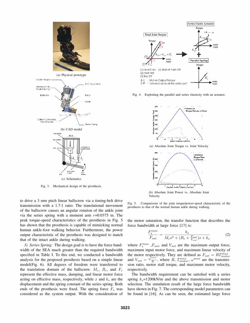
The basic architecture of our mechanical design is a physicalspring, configured in parallel to a high power output force-controllable actuator (Fig. 3). The parallel spring and the force-controllable actuator serve as the spring component and thetorque source, respectively.
As can be seen in Fig. 3(c), there are five main mechanicalelements in the system: a high power output d.c. motor,a transmission, a series spring, an unidirectional parallelspring, and a carbon composite leaf spring prosthetic foot.We combine the first three components to form a force-controllable actuator, called Series-Elastic Actuator(SEA). ASEA, previously developed for legged robots [17], consists ofa dc motor in series with a spring (or spring structure) via amechanical transmission. The SEA provides force control bycontrolling the extent to which the series spring is compressed.Using a linear potentiometer, we can obtain the force appliedto the load by measuring the deflection of the series spring.
In this application, we use the SEA to modulate the jointstiffness as well as provide the constant offset torque ∆τ . Ascan be seen in Fig. 4, the SEA provides a stiffness value KCP
during CP and a stiffness value KCD1 from CD to PP. Frompoints (4) to (3), it supplies both the stiffness value KCD1 anda constant, offset torque ∆τ .
Due to the demanding output torque and power require-ments, we incorporate a physical spring, configured in parallelto the SEA, so that the load borne by the SEA is greatlyreduced. Because of this fact, the SEA will have a substantiallylarge force bandwidth to provide the active push-off during PP.To avoid hindering the foot motion during swing phase, theparallel spring is implemented as an unidirectional spring thatprovides an offset rotational stiffness value Kr
p only when theankle angle is larger than zero degree (Fig. 4).
The elastic leaf spring foot is used to emulate the function ofa human foot that provides shock absorption during foot strike,energy storage during the early stance period, and energyreturn in the late stance period. A standard prosthetic foot,Flex Foot LP Vari-Flex [12] is used in the prototype.
A. Component Selections
Broadly speaking, there are three main design decisionsin this project: (1) choosing the parallel spring stiffness, (2)choosing the actuator and transmission, and (3) choosing theseries spring stiffness.
1) Parallel Spring: A linear parallel spring kp with amoment arm Rp in Fig. 3(c) provides a rotational joint stiffnessKr
p ,Kr
p = (kp)(Rp)2 (1)
The goal is to select the moment arm and the spring constant toprovide the suggested offset stiffness in Table I. In the physicalsystem, due to the size and weight constraints, kp and Rp
were chosen to be 770KN/m and 0.022m, respectively. Con-sequently, Kr
P =385rad/s. Because this value is smaller thanthe suggested offset stiffness(550rad/s), the SEA supplementsthe required joint stiffness (Fig. 4).
2) Actuator and Transmission: The goal is to select anactuator and a transmission to bracket the maximum torqueand speed characteristics of the prosthesis, so as to match theintact ankle torque/power-speed requirements (Fig. 5). In ourdesign, a 150 W d.c. brushed motor from Maxon, Inc (RE-40)was used. For the drive train system, the motor was designed
3022
(a) Physical prototype
(b) CAD model
(c) Schematics
Fig. 3. Mechanical design of the prosthesis.
to drive a 3 mm pitch linear ballscrew via a timing-belt drivetransmission with a 1.7:1 ratio. The translational movementof the ballscrew causes an angular rotation of the ankle jointvia the series spring with a moment arm r=0.0375 m. Thepeak torque-speed characteristics of the prosthesis in Fig. 5has shown that the prosthesis is capable of mimicking normalhuman ankle-foot walking behavior. Furthermore, the poweroutput characteristic of the prosthesis was designed to matchthat of the intact ankle during walking.
3) Series Spring: The design goal is to have the force band-width of the SEA much greater than the required bandwidthspecified in Table I. To this end, we conducted a bandwidthanalysis for the proposed prosthesis based on a simple linearmodel(Fig. 6). All degrees of freedom were transferred tothe translation domain of the ballscrew. Me, Be, and Fe
represent the effective mass, damping, and linear motor forceacting on effective mass, respectively, while x and ks are thedisplacement and the spring constant of the series spring. Bothends of the prosthesis were fixed. The spring force Fs wasconsidered as the system output. With the consideration of
Fig. 4. Exploiting the parallel and series elasticity with an actuator.
(a) Absolute Joint Torque vs. Joint Velocity
(b) Absolute Joint Power vs. Absolute JointVelocity
Fig. 5. Comparisons of the joint torque/power-speed characteristic of theprosthesis to that of the normal human ankle during walking.
the motor saturation, the transfer function that describes theforce bandwidth at large force [17] is:
Fmaxs
Fsat=
ks
Mes2 + (Be + Fsat
Vsat)s + ks
(2)
where Fmaxs ,Fsat, and Vsat are the maximum output force,
maximum input motor force, and maximum linear velocity ofthe motor respectively. They are defined as Fsat = RTmax
motor
and Vsat = ωmax
R , where R, Tmaxmotor, ωmax are the transmis-
sion ratio, motor stall torque, and maximum motor velocity,respectively.
The bandwidth requirement can be satisfied with a seriesspring ks=1200kN/m and the above transmission and motorselection. The simulation result of the large force bandwidthhave shown in Fig. 7. The corresponding model parameters canbe found in [16]. As can be seen, the estimated large force
3023

Fig. 6. A simple linear model of the prosthesis for the bandwidth analysis.
Fig. 7. Simulation result for the large force bandwidth due to motorsaturation.
bandwidth of the system with and without the parallel springwas at 9.4Hz (at 50Nm) and 3.8Hz (at 120Nm), respectively.As the parallel spring shared some of the payloads of theSEA, the required peak force for the system was significantlyreduced. With the parallel spring, the estimated force band-width were much larger than the designed one.
IV. CONTROL SYSTEM
Finite-state controllers are usually used in locomo-tion assistive/prosthetic devices such as A/K prostheses[18][13]because gait is repetitive between strides and, within astride, and can be characterized into distinct finite numbers ofsub-phases. The human ankle also demonstrates such kind ofperiodic and phasic properties during walking. This motivatesthe usage of a finite-state controller to control the poweredprosthesis. Referring to Section II-B, the finite-state controllershould be designed to replicate the target stance phase be-havior. To this end, a finite-state controller for level-groundwalking was implemented (Fig. 8). The details of the proposedfinite-state controller for level-ground walking are discussed asfollows.
A. Stance Phase Control
Three states (CP, CD, and PP) were designed for stancephase control. Descriptions for each state are shown below.
• CP begins at heel-strike and ends at mid-stance. DuringCP, the prosthesis outputs a joint stiffness, KCP .
• CD begins at mid-stance and ends at PP or toe-off,depending on the measured total ankle torque Tankle.
During CD, the prosthesis outputs a joint stiffness, KCD,where KCD = Kr
p + KCD1.• PP begins only if the measured total ankle torque, Tankle
is larger than the predefined torque threshold, τpp. Oth-erwise, it remains in state CD until the foot is off theground. During PP, the prosthesis outputs a constantoffset torque, ∆τ superimposing the joint stiffness, KCD
as an active push-off.KCP , KCD, τpp, and ∆τ are the main parameters affecting
the ankle performance during the stance phase control. Inparticular, the offset torque is directly related to the amountof net work done at the ankle joint. These parameter valueswere chosen based on the user’s walking preference duringexperiments. The stance phase control for a typical gait cycleis graphically depicted in Fig. 8.
B. Swing Phase Control
Another three states (SW1, SW2, and SW3) were designedfor the swing phase control. Descriptions for each state areshown below.
• SW1 begins at toe-off and ends in a given time period, tH .During SW1, the prosthesis servos the foot to a predefinedfoot position, θtoeoff for foot clearance.
• SW2 begins right after SW1 and finishes when the footreaches zero degree. During SW2, the prosthesis servosthe foot back to the default equilibrium position θd = 0.
• SW3 begins right after SW2 and ends at the next heel-strike. During SW3, the controller will reset the systemto impedance mode and output a joint stiffness, KCP .
The time period, tH and predefined foot position, θtoeoff areall tuned experimentally.
C. Sensing for State Transitions
During state transition and identification, the system mainlyrelied on four variables:
• Heel contact(H). H=1 indicates that the heel is on theground, and vice versa.
• Toe contact(T). T=1 indicates that the toe is on theground, and vice versa.
• Ankle angle (θ)• Total ankle torque (Tankle)
All these triggering information can be obtained using localsensing; including foot switches to measure heel/toe contact,ankle joint encoder to measure the ankle angle, and the linearspring potentiometer to measure joint torque.
D. Low-level Servo Controllers
To support the proposed stance phase and swing phasecontrols, three types of low-level servo controllers were de-veloped: (i) a high performance torque controller to providean offset torque during push-off as well as facilitate thestiffness modulation; (ii) an impedance controller to modulatethe joint stiffness during the entire stance phase; (iii) a positioncontroller to control the foot position during the swing phase.The details of the controller designs can be found in [16].
3024

Fig. 8. The finite-state control for a typical gait cycle.
V. SENSORS AND COMPUTING PLATFORM
This section describes the electronics hardware used forimplementing the proposed controller onto the MIT poweredankle-foot prosthesis. Fig. 9 shows the schematics of theoverall computer system. The computer system contained anonboard computer (PC104) with a data acquisition card, powersupply, and motor amplifiers. The system was powered by a48V, 4000mAh Li-Polymer battery pack. A custom breakoutboard interfaced the sensors to the D/A board on the PC104as well as provided power the signal conditioning boards. Thesystem runs the Matlab Kernel for xPC target application. Thetarget PC (PC104) can communicate with a host computervia Ethernet. The host computer sends control commands andobtains sensory data from the target PC104.
Three state variables, including heel/toe contact, ankleangle, and joint torque, were measured to implement theproposed finite-state controller. We installed a 5 kΩ linearpotentiometer across the series springs to estimate the jointtorque. We also mounted a 500-line quadrature encoder inbetween the parent link and child link mounting plates tomeasure the joint angle. Six capacitive force transducers wereplaced on the bottom of the foot: two sensors beneath the heeland four beneath the forefoot region.
Fig. 9. Schematics of the overall computer system.
A mobile computing platform was developed that allowedus to conduct untethered walking experiments outside thelaboratory. The mobile platform was mounted on an externalframe backpack and most of the electronic components were
mounted on the platform, including a PC104, a power supply,I/O Cards, and a motor amplifier. Using cabling, the prosthesiswas connected to the I/O board and motor amplifier on theplatform.
VI. EXPERIMENTS
In this investigation, we measured the rate of oxygen con-sumption of three male, unilateral transtibial amputees( Ages:40-57 yrs, Height: 173-176 cm, Weight: 71-86kg) walkingat self-selected speeds for two conditions: (1) using theirconventional passive prostheses; and (2) using the poweredprosthesis. Their prostheses (with shoes) weighted about 1.5-2 kg, while the powered prosthesis weighted 3-4 kg, dependingon the fitting of participants. Initial walking experimentswere performed on the Johnson Indoor Track at MIT. Beforeconducting the metabolic cost study, each participant wasgiven enough time to acclimatize to the powered prosthesis.Each participant communicated desired parameter values to aseparate operator during the walking trails. By the end of theacclimatization, we obtained a set of control system parametersthat provided the most favorable prosthetic ankle response ata self-selected walking speed.
We then measured the rate of oxygen consumption of theparticipant for the two experimental conditions. During theexperiment, walking speed was controlled by having the partic-ipant follow a modified golf caddy set to a desired speed. Theself-selected walking speed with the powered prosthesis wasused for the two conditions. Sensory data (e.g. joint torque)from the prosthesis was also captured. Detailed information ofthe experimental protocol can be obtained from [16].
VII. RESULTS AND DISCUSSION
During the experiments, it was discovered that the proposedfinite state machine performed robustly and was capable ofmimicking the target stance phase behavior. All amputeeparticipants and the prosthetist were satisfied with the per-formance of the prosthesis. In general, it took less than 20minutes for each amputee participant to adapt to the poweredprosthesis. The prosthetist reported that with the poweredprosthesis each participant moved with a more natural gaitthan with their conventional passive-elastic prosthesis.
Fig. 10 shows an experimental ankle torque-angle plotfor one gait cycle. The experimental result demonstrates thesystem’s capacity to track the target stance phase behavior anddeliver sufficient net positive work at the ankle joint to propelan amputee. It is noted that the measured ankle torque-anglecurve flattens around the peak torque region because the actualsystem took time (about 50ms) to output the offset torque.Also, the toe-off was set to be triggered before the ankle jointreaches the zero torque level (Fig. 10) because that can provideenough time for the control system to switch from impedancecontrol mode to position control mode at the transition fromstance to swing.
The measured, steady state rate to oxygen consumption
3025

Fig. 10. An experimental ankle torque-angle plot for the powered prosthesisacross a single gait cycle with positive net work. The red cross indicates thetime at which the prosthesis begins actively plantar flexing.
Fig. 11. The metabolic cost of transport for three participants.
was used to compute the metabolic cost of transport2(COT),that is a standard measure of amputee walking economy. Thestandard formula from [19] was used to convert the rate ofoxygen consumption into the metabolic power of walking. Themetabolic COT for each participant is shown in Fig. 11. Thepowered prosthesis was found to decrease the COT of amputeeparticipants from 7% to 20% compared to the conventionalpassive-elastic prostheses, even though the powered systemwas two-fold heavier than the conventional devices. Thishighlights the benefit of performing net positive work duringstance to amputee ambulation. It also highlights the fact thatthe weight of the prosthesis is not necessarily a detriment tothe clinical performance of a prosthetic intervention. Clearly,the weight of a powered ankle-foot prosthesis may not hinderan amputee’s gait as long as the prosthesis can providesufficient power output at terminal stance. In additional to themeasurements, amputee participants reported that the poweredprosthesis did not feel heavy when the system was active.
VIII. CONCLUSION
In this paper, a novel, powered ankle-foot prosthesis wasbuilt that comprises a unidirectional spring, configured inparallel with a force-controllable actuator with series elasticity.The prosthesis was controlled to mimic the normal humanankle walking behavior. The initial clinical study showed that
2The metabolic cost of transport is defined as the metabolic energy requiresto move per unit distance per unit weight [15].
the powered prosthesis improves amputee metabolic economyfrom 7% to 20% compared to the conventional passive-elasticprostheses, even though the powered system is twofold heavierthan the conventional devices. These results highlighted thebenefits of performing net positive work at the ankle jointto amputee ambulation. The future work includes developinga more viable prototype ankle-foot prosthesis that fits bothhuman foot/ankle dimensions and geometry, with compactintegrated battery and other electronic components. Also, itis necessary to conduct a comprehensive biomechanical gaitstudy on the amputee participants to provide a biomechanicalmechanism for the observed metabolic reduction. It is ourhope that this work will lead to a new direction for furtheradvancement of an ankle-foot prosthesis.
ACKNOWLEDGMENT
The authors wish to thank B. Deffenbaugh, and L. Magnus-son for their contributions in the clinical study.
REFERENCES
[1] D. A. Winter, “Biomechanical motor pattern in normal walking,” Journalof Motor Behavior, Vol. 15, No. 4, pp. 302 - 330, 1983.
[2] M. Palmer, “Sagittal plane characterization of normal human anklefunction across a range of walking gait speeds,” Master’s Thesis, Mas-sachusetts Institute of Technology, 2002.
[3] D. H. Gates, “Characterizing ankle function during stair ascent, descent,and level walking for ankle prosthesis and orthosis design,” Master’sthesis, Boston University, 2004.
[4] S. Ron, Prosthetics and Orthotics: Lower limb and Spinal. LippincottWilliams & Wilkins, 2002.
[5] D. A. Winter and S. E. Sienko, “Biomechanics of below-knee amputeegait,” Journal of Biomechanics, Vol. 21, No. 5, pp. 361-7, 1988.
[6] N. H. Molen, “Energy/speed relation of below-knee amputees walking onmotor-driven treadmill,” Int. Z. Angew. Physio, Vol. 31, pp.173, 1973.
[7] G. R. Colborne, S. Naumann, P. E. Longmuir, and D. Berbrayer, “Analysisof mechanical and metabolic factors in the gait of congenital below kneeamputees,” Am. J. Phys. Med. Rehabil., Vol. 92, pp. 272 - 278, 1992.
[8] G. K. Klute, J. Czerniecki, and B. Hannaford, “Development of poweredprosthetic lower limb,’ Proc. 1st National Mtg, Veterans Affairs Rehab.R&D Service, Washington, DC, October 1998.
[9] S. H. Collins and A. D. Kuo, “Controlled energy storage and return pros-thesis reduces metabolic cost of walking,” Proc. on ISB XXth Congressand the American Society of Biomechanics Annual Meeting, Cleveland,Ohio, pp. 804, August 2003.
[10] C. Li, et al.,“Research and development of the intelligently-controlledprosthetic ankle joint,“ Proc. of IEEE Int. Conf. on Mechatronics andAutomation, Luoyang, China, pp. 1114-1119, 2006.
[11] US Patent 6443993, Sept. 3, 2002.[12] www.ossur.com.[13] K. Koganezawa, and I. Kato, “Control aspects of artificial leg,” IFAC
Control Aspects of Biomedical Engineering, pp.71-85, 1987.[14] S. K. Au, P. Dilworth, and H. Herr, “An ankle-foot emulator system
for the study of human walking biomechanics,” Proc. IEEE Int. Conf. onRobotics and Automation, Orlando, FL, pp. 2939-2945, May 2006.
[15] V. T. Inman, H. J. Ralston, and F. Todd, Human walking. Baltimore:Williams and Wilkins; 1981.
[16] S. K. Au, “Powered Ankle-Foot Prosthesis for the Improvement ofAmputee Walking Economy,” Ph.D. Thesis, Massachusetts Institute ofTechnology, 2007.
[17] D. Robinson, “Design and an analysis of series elasticity in closed-loop actuator force control,” Ph.D. Thesis, Massachusetts Institute ofTechnology, 2000.
[18] D. L. Grimes, “An active multi-mode above-knee prosthesis controller,”Ph.D. Thesis, Massachusetts Institute of Technology,1976.
[19] J.M. Brockway, “Derivation of formulae used to calculate energy expen-diture in man,” Human Nutrition: Clinical Nutrition, Vol. 41, pp. 463-471,1987.
3026