power xpert meter 350 din rail power meter mn150011en · voltage, current, power, frequency and...
TRANSCRIPT

Power Xpert Meter 350 DIN-Rail power meter
MN150011EN

ii Power XPert Meter 350 DIN-raIl Power Meter MN150011EN September 2019 www.eaton.com
DISCLAIMER OF WARRANTIES AND LIMITATION OF LIABILITYThe information, recommendations, descriptions and safety notations in this document are based on Eaton Corporation’s (“Eaton”) experience and judgment and may not cover all contingencies. If further information is required, an Eaton sales office should be consulted. Sale of the product shown in this literature is subject to the terms and conditions outlined in appropriate Eaton selling policies or other contractual agreement between Eaton and the purchaser.
THERE ARE NO UNDERSTANDINGS, AGREEMENTS, WARRANTIES, EXPRESSED OR IMPLIED, INCLUDING WARRANTIES OF FITNESS FOR A PARTICULAR PURPOSE OR MERCHANTABILITY, OTHER THAN THOSE SPECIFICALLY SET OUT IN ANY EXISTING CONTRACT BETWEEN THE PARTIES. ANY SUCH CONTRACT STATES THE ENTIRE OBLIGATION OF EATON. THE CONTENTS OF THIS DOCUMENT SHALL NOT BECOME PART OF OR MODIFY ANY CONTRACT BETWEEN THE PARTIES.
In no event will Eaton be responsible to the purchaser or user in contract, in tort (including negligence), strict liability or other-wise for any special, indirect, incidental or consequential damage or loss whatsoever, including but not limited to damage or loss of use of equipment, plant or power system, cost of capital, loss of power, additional expenses in the use of existing power facilities, or claims against the purchaser or user by its customers resulting from the use of the information, recom-mendations and descriptions contained herein. The information contained in this manual is subject to change without notice.

iii
MN150011EN
Power XPert Meter 350 DIN-raIl Power Meter MN150011EN September 2019 www.eaton.com
Contents
1. INTRODUCTION . . . . . . . . . . . . . . . . . . . . . . . . . . . . . . . . . . . . . . . . . . . . . . . . . . 11.1 Meter overview . . . . . . . . . . . . . . . . . . . . . . . . . . . . . . . . . . . . . . . . . . . . . . . . . . . .1
1.2 Areas of application . . . . . . . . . . . . . . . . . . . . . . . . . . . . . . . . . . . . . . . . . . . . . . . . .1
1.3 Product features . . . . . . . . . . . . . . . . . . . . . . . . . . . . . . . . . . . . . . . . . . . . . . . . . . . .1
2. INSTALLATION . . . . . . . . . . . . . . . . . . . . . . . . . . . . . . . . . . . . . . . . . . . . . . . . . . . 22.1 Appearance and dimensions . . . . . . . . . . . . . . . . . . . . . . . . . . . . . . . . . . . . . . . . . .3
2.2 Installation methods . . . . . . . . . . . . . . . . . . . . . . . . . . . . . . . . . . . . . . . . . . . . . . . .3
2.3 Wiring . . . . . . . . . . . . . . . . . . . . . . . . . . . . . . . . . . . . . . . . . . . . . . . . . . . . . . . . . . .4
3. OPERATION AND APPLICATION . . . . . . . . . . . . . . . . . . . . . . . . . . . . . . . . . . . . 143.1 Display panel and keys . . . . . . . . . . . . . . . . . . . . . . . . . . . . . . . . . . . . . . . . . . . . .14
3.2 Display mode and key operations . . . . . . . . . . . . . . . . . . . . . . . . . . . . . . . . . . . . .15
3.3 Parameter display and key operations . . . . . . . . . . . . . . . . . . . . . . . . . . . . . . . . . .16
3.4 Settings and operations: . . . . . . . . . . . . . . . . . . . . . . . . . . . . . . . . . . . . . . . . . . . .17
3.5 Meter configuration . . . . . . . . . . . . . . . . . . . . . . . . . . . . . . . . . . . . . . . . . . . . . . . .19
3.6 Energy pulse output . . . . . . . . . . . . . . . . . . . . . . . . . . . . . . . . . . . . . . . . . . . . . . .20
4 FUNCTIONS FUNCTIONS AND SOFTWARE . . . . . . . . . . . . . . . . . . . . . . . . . . 224.1 Introduction to PXM350 utility software . . . . . . . . . . . . . . . . . . . . . . . . . . . . . . . .22
4.2 Parameter settings . . . . . . . . . . . . . . . . . . . . . . . . . . . . . . . . . . . . . . . . . . . . . . . .24
4.3 Real-time metering . . . . . . . . . . . . . . . . . . . . . . . . . . . . . . . . . . . . . . . . . . . . . . . .30
4.4 Measurement function . . . . . . . . . . . . . . . . . . . . . . . . . . . . . . . . . . . . . . . . . . . . .31
4.5 Event logging . . . . . . . . . . . . . . . . . . . . . . . . . . . . . . . . . . . . . . . . . . . . . . . . . . . .35
4.6 Alarm function . . . . . . . . . . . . . . . . . . . . . . . . . . . . . . . . . . . . . . . . . . . . . . . . . . . .37
4.7 Incorrect connection detection . . . . . . . . . . . . . . . . . . . . . . . . . . . . . . . . . . . . . . .39
4.8 Sealing function . . . . . . . . . . . . . . . . . . . . . . . . . . . . . . . . . . . . . . . . . . . . . . . . . . .40
4.9 Device Information . . . . . . . . . . . . . . . . . . . . . . . . . . . . . . . . . . . . . . . . . . . . . . . .42
5 COMMUNICATION . . . . . . . . . . . . . . . . . . . . . . . . . . . . . . . . . . . . . . . . . . . . . . . 445.1 Modbus protocol information . . . . . . . . . . . . . . . . . . . . . . . . . . . . . . . . . . . . . . . .45
5.2 Communication format . . . . . . . . . . . . . . . . . . . . . . . . . . . . . . . . . . . . . . . . . . . .46
5.3 Application details . . . . . . . . . . . . . . . . . . . . . . . . . . . . . . . . . . . . . . . . . . . . . . . . .47
5.4 BACnet MSTP . . . . . . . . . . . . . . . . . . . . . . . . . . . . . . . . . . . . . . . . . . . . . . . . . . . .72
APPENDIX A – FUNCTIONS LIST . . . . . . . . . . . . . . . . . . . . . . . . . . . . . . . . . . . . . 76
APPENDIX B – TECHNICAL SPECIFICATIONS AND PARAMETERS . . . . . . . . . . 77
APPENDIX C – REVISION HISTORY . . . . . . . . . . . . . . . . . . . . . . . . . . . . . . . . . . . 78
APPENDIX D – ALARM PARAMETERS COMPARISON TABLE . . . . . . . . . . . . . . 78
APPENDIX E – REGISTER 10AEH-10AFH METER EVENT FLAGS: BIT32 . . . . . 78

iv
MN150011EN
Power XPert Meter 350 DIN-raIl Power Meter MN150011EN September 2019 www.eaton.com
Please read this manual carefully before installation, operation and maintenance of the Power Xpert® Meter (PXM) 350. The following symbols in this manual are used to provide warning of danger or risk during the installation and operation of the meters.
WARNING Electric shock symbol: Carries information about procedures which must be followed to reduce the risk of electric shock and danger to personal health.
WARNING Safety alert symbol: Carries information about circumstances which if not considered may result in injury or death.
WARNING Prior to maintenance and repair, the equipment must be de-energized and grounded. All maintenance work must be performed by qualified, competent accredited profes-sionals who have received formal training and have experience with high voltage and current devices. Eaton shall not be responsible or liable for any damages or injuries caused by improper meter installation and/or operation.
Welcome to the PXM350!
You have purchased an advanced, versatile, multifunction power meter.
Please note the following chapter descriptions in order to utilize the power meter properly.
Chapter 1 introduces the basic PXM350 features and application areas.
Chapter 2 introduces the PXM350 installation and wiring methods in detail.
Chapter 3 walks through how to operate the PXM350 via the display panel, display measurement data and parameter settings.
Chapter 4 introduces main functions with the included software.
Chapter 5 introduces communication related information, including communication protocol format and parameter address table.
Appendix provides PXM350 technical specifications and ordering information.

1
1. Introduction
Power XPert Meter 350 DIN-raIl Power Meter MN150011EN September 2019 www.eaton.com
1. Introduction1.1 Meter overviewThe PXM350 series is a DIN rail-mounted, three phase energy meter that is small in size with high accuracy. The meter is equipped with an easy to read liquid crystal display (LCD) which conveys all the important data. It is ideal for building energy management systems, energy monitoring and energy metering systems.
Energy
The PXM350 series supports bi-directional active energy measurements, as well as two-way reactive power energy metering, and four quadrant reactive power energy metering. It also supports apparent energy metering, the cumulative energy metering (energy import + energy export), and net energy metering (input power - output power).
Measurement function
The PXM350 series meters provides real-time RMS measurement of the instantaneous voltage, current, power, frequency and power factor. Measurements can be viewed through the meter display as well as the PXM350 utility software.
Demand
This product provides demand measurement of current, active power, reactive power and apparent power. It also provides demand forecasting as well as the peak demand.
System event logging
The PXM350 series meter can record the time and date regarding important parameter events.
• Alarm function
Supports multiple parameter alarms, and can be configured to trigger relay output.
Communication
This meter supports Modbus RTU and BACnet MSTP communication over RS-485.
1.2 Areas of application
School Hotels and buildings Industrial environment Rail transport
Public facilities Distribution cabinet Energy management system
1.3 Product featuresMultifunction, high accuracy
PXM350 series meter has data collection and management for energy and multi-parameters measurement. It also features demand measurement and event logging.
The measurement accuracy of energy, power, voltage, and current is 0.5%.
Small size, convenient installation
The appearance and dimension of the PXM350 series meter is designed in accordance with the IEC 35 mm DIN standard.

2
2. Installation
Power XPert Meter 350 DIN-raIl Power Meter MN150011EN September 2019 www.eaton.com
Clear display
The PXM350 series features a clear display to provide visibility in all environments. All measurement parameters can be found and easily accessed through the display. The LCD display has backlight support that can aid users in weak lighting environments.
Safety
PXM350 series product has both an electronic and physical sealing function. It is designed is such a way that it cannot be opened without leaving signs of tampering. Users cannot change the parameters through the display when the electronic sealing is closed, and important parameters cannot be changed through communication, thus preventing data or configurations from being altered.
Convenient wiring
It supports both high voltage systems and low voltage systems, as well as both three-phase three-wire systems and three-phase four-wire systems. Users can choose the appropriate wiring configuration for the PXM350 series meter. The PXM350 series meter can be used for single phase systems as well.
Wiring check
The PXM350 series meter has a connection error feature that helps to identify wiring errors.
2. InstallationBefore installationThe installation must be performed by qualified, competent accredited professionals who has received formal training and has experience with high voltage and current devices. Appropriate safety wear (gloves, glasses, arc flush suit, etc.) is mandatory to ensure safe installation.
During normal meter operation, caution should be used when handling the following as high voltage may be present:
• Terminal blocks
• Current/potential transformer leads and the related circuits
• All primary and secondary circuits may contain lethal current and voltage.
• Contact with current channels must be avoided.
• The power meter and I/O modules are suitable for Installation Category III and should not be used in Installation Category IV applications. Avoid contact with the meter termi-nals once installation is complete.
• Do not supply input voltage above the rated maximum limit of the power meter and devices connected to it. Before energizing the meter, please refer to the meters label and specifications.
• Do not perform high voltage test or insulation experiments to output, input or commu-nication terminals.
• The use of CT shorting terminal blocks are recommended on 5A/1A or 80/100/200mA CT's. Fuses are recommended for Voltage and Control Power circuits. Fuse ratings may be selected to protect the secondary instrumentation wiring. Current transformers need to be grounded (5A/1A).
• Use dry cloth to wipe the meter.
This chapter mainly describes the installation process of the PXM350 series meter, which is a very important step in using the meter correctly. This chapter provides information and diagrams about how to install the meter. Before installing the meter, please read through this section first.

3
2. Installation
Power XPert Meter 350 DIN-raIl Power Meter MN150011EN September 2019 www.eaton.com
2.1 Appearance and dimensions
Figure 1. PXM350 front display.
Figure 2. PXM350 meter front and side dimensions.
2.2 Installation methodsEnvironmental
Before installation, please check the environment, temperature, and humidity to ensure the PXM350 series meter is being placed in an environment that are within temperature and humidity specifications.
ote:N Temperature and humidity of the environment must comply with the requirement of PXM350, otherwise it may cause the meter damage.
Temperature
PXM350 operating temperature is -25 to 75°C. Exceeding this temperature range will cause damage to the meter and will affect the accuracy and functionality. Please note this can influence the meters life negatively if the meter operates in extremely high or extremely low temperatures. PXM350 storage temperature range is -40 to +85°C.
Humidity
5% to 95% non-condensing.
Location
PXM350 series meter should be installed in a dry and dust free environment. Avoid expos-ing the meter to excessive heat, radiation and high electrical noise sources.
Dimensions
108.0 (4.25)
90.0
(3.
54)
35.5
(1.4
0)
45.0
(1.7
7)
62.5(2.46)
7.0(0.28)
17.5(0.69)
15.0(0.60)
Units: mm (in)
12.0(0.47)
12.0(0.47)
7.0(0.28)
4.5(0.18)

4
2. Installation
Power XPert Meter 350 DIN-raIl Power Meter MN150011EN September 2019 www.eaton.com
Installation steps:
This product is DIN railed mounted and fits on a standard 35 mm rail.
1. To install the meter on the rail insert the top of the rail into the groove on the back of the meter. Pull the metal clips back and slide the rail across the groove of the meter.
Figure 3. Step A.
Figure 4. Step B.
2.3 WiringThe terminals of the PXM350 series can be accessed by first removing the terminal covers on the meter.
1. To open the terminal cover, remove the seal if applicable, and then unscrew the sealing screws and lift the cover upwards to remove.
Figure 5. Removing terminal cover.

5
2. Installation
Power XPert Meter 350 DIN-raIl Power Meter MN150011EN September 2019 www.eaton.com
2. To attach the bottom terminal cover back onto the meter, place the left side of the cover down into the groove first and then press down onto the right side, see figure 6. When installed correctly, you will hear a clicking sound. To attach the top cover place the right side of the cover down into the groove and press down onto the left side.
Figure 6. Attaching terminal cover onto meter.
3. After inserting the cover, tighten the sealing screws and apply a seal if required for tamper detection.
Figure 7. Securing the terminal cover.

6
2. Installation
Power XPert Meter 350 DIN-raIl Power Meter MN150011EN September 2019 www.eaton.com
Terminals:
This manual uses V1, V2, V3 to represent three-phase conductors, which would be the same as Va, Vb, Vc.
Figure 8. PXM350 Series terminals.
• Communications terminal: A(+), B(-), S
• Pulse output: P1, P2
• Auxiliary power: L, N
• Voltage inputs: V1, V2, V3, VN
• Current inputs: I11, I12, I21 I22, I31, I32, I41, I42
• Relay output: R1, R2
Auxiliary power supply:
The PXM350 series meter requires a power supply of 100 ~ 415 Vac at 50/60 Hz. For use of other power supply voltage selections please contact the manufacturer. The meter typically has small power consumption (less than 1W) so the power supply can be an independent power supply, or can also be obtained from the metered circuit.
The power supply terminals respectively are: L, N.
The typical auxiliary power wiring is as follows:
Figure 9. Power supply connections for PXM350.
The meter requires AWG22-16 as the wires to connect the power supply.
A fuse (typical 1A/250Vac) is suggested to be used when connecting the power supply to the meter. The fuse rating can be sized to protect the instrumentation wiring.
ote:N Check the power supply rating before wiring. Please confirm by reading the power supply information on the silver sticker at the side of the meter.
A B S I11 I12 I21 I22 I31 I32 I41 I42
L N V1 V2 V3 VNR1 R2 P1 P2SET
1A FuseL
N PXM350Power supply

7
2. Installation
Power XPert Meter 350 DIN-raIl Power Meter MN150011EN September 2019 www.eaton.com
Voltage input:
The maximum input voltage for the PXM350 series meter cannot exceed 400LN/690LL VAC RMS for three phase or 400LN VAC rms for single phase. The voltage input requires a fuse.
Potential transformer (PT) must be used for high voltage systems that are greater than the meters rated voltage. The rated secondary output from the PT is typically 100-120 V. Please make sure to select an appropriate PT to maintain the measurement accuracy of the PXM350 series meter. When connecting using the WYE configuration wiring method, the PT's rated input or primary side rated voltage should be equal to or close to the phase voltage of the system to utilize the full range of the PT being used. When connecting using the delta configuration wiring method, the PT's rated input or primary side rated voltage should be equal to or close to the line voltage of the system.
A fuse rated for protecting the instrumentation wiring/600 V should be used when connect-ing the voltage inputs to the meter.
The meter requires the wire size to be AWG22-14.
ote:N Under no circumstances should the secondary of the PT be shorted. The secondary of the PT should be grounded at one end. Please refer to the wiring diagram section for further details.
Ordering InformationPXM 350 MA 6 3 2 1
Current input:
The ordering information table above shows 4 types of current inputs that are supported by the PXM350. The selection of current sensor type depends on the application. Review the specifications for each type of sensor to determine which is most appropriate before select-ing the current sensor and meter current input to order. Secondary lead length should be as short as possible to reduce the effect of lead length on accuracy.
1 80/100/200mA These milli-amp current sensors are often used in submetering applications. The smaller output current of these current sensors reduces the losses in the secondary leads permitting longer lead lengths between the meter and the sensor.
2 333mV 333mV current sensors are popular in retrofit applications. The 333mV sensor output does not present the open circuit hazards associated when the secondary current circuit is open on a current transformer that is designed to drive a current output. However, 333mV secondary leads should be routed away from sources of electrical field such as power conductors since the low signal levels are subject to distortion from nearby sources of noise.
3 5A/1A configurable 5A Current Transformers are the traditional selection for metering and protection in Low Voltage Equipment applications. This Selection is also configurable for 1A nominal Current Transformers.
4 Rogowski Coil Rogowski Coil sensors are convenient for field installation, especially when metering Multiple conductors per phase.
ote:N When using mV, Rogowski Coil or mA style current sensors, the secondary sensor leads must not be grounded.
Current input
3 = 333 mV5 = 5 A/1 A configurableR = Rogowski coil** Bidirectional energy
only. No 4th CT input.
Model type
2 = Pulse output, Modbus, BACnet MSTP, TOU
4 = Pulse output, Modbus, BACnet MSTP, TOU, Bidirectional energy, 4th current input
Relay output
1 = 1 relay output

8
2. Installation
Power XPert Meter 350 DIN-raIl Power Meter MN150011EN September 2019 www.eaton.com
WARNING When using 1A/5A or mA style current transformers, the secondary circuit must not be open before de-energizing the circuit being monitored. If a current transformer sec-ondary circuit is open circuited under load, hazardous voltages can be present. The use of Shorting Terminal Blocks is recommended. No fuses or switches should be present in the CT secondary circuit.
Vn Connection
Vn is the reference point of the PXM350 series meter voltage input. Different system wiring modes require different Vn connection methods. Please refer to the wiring diagram section for more details.
PXM350 series meter supports different wiring configurations for both three phase and single phase systems. Please read this section carefully before choosing the suitable wiring method for your power system.
In the PXM350 series meter please make sure that the wiring connection mode to ensure the measurement accuracy of meter. Here are some of the common installation methods, their respective diagrams and meter configurations for the PXM350 series meter.
1 Three phase: 4 wire-connection: (three phase with a neutral) Wiring mode 3LN. Three CT's needed for this connection. Common voltages for this connection: 120V LN/208V LL, 277V LN/480V LL
Figure 10. PXM350MA6X4X 3LN wiring diagram using 5A/1A CTs.
ote:N Rogowski coil current input does not support neutral current measurement
Figure 11. PXM350 LN wiring diagram using 5A/1A CTs .
*1A Fuse is typical, but fuse can be selected to protect the instrumentation wiring.
ote:N Neutral Current Sensor is optional.
ABCNLine
1A Fuse *
PXM350
Load
CT shorting block
I11I12I21I22I31I32I41I42
VN V3 V2 V1
*1A Fuse is typical, but fuse can be selected to protect the instrumentation wiring.
A B C NLine
1A Fuse*
PXM350
Load
CT shorting blockVN V3 V2 V1I11
I12I21I22I31I32I41I42

9
2. Installation
Power XPert Meter 350 DIN-raIl Power Meter MN150011EN September 2019 www.eaton.com
Figure 12. 3LN using 333mV, mA and Rogowski Coil CTs.
2 Three phase: 3 wire-connection (three phase without a neutral) The wiring mode is set to 2LL. Two CT's needed for this connection. Note: Output of the CT is 5A/1A and mA. With potential transformers (PTs) - PTs are required if the system voltage is higher than 690 V LL. Instead of connecting the voltage lines directly to the meter, the voltage lines are connected to the meter using PTs. The PTs should be connected as shown below.
ote:N Only two PTs are needed for this connection.
Figure 13. 2LL wiring diagram using 5A/1A CTs and PTs.
Figure 14. 2LL using 333mV, mA and Rogowski coil CT.
*1A Fuse is typical, but fuse can be selected to protect the instrumentation wiring.
A B C NLine
1A Fuse*
VN V3 V2 V1
PXM350
Load
1
2
3
4
5
10 9 8 7I11I12I21I22I31I326
CT shorting block
A B CLine
1A Fuse*
PXM350
Load
VN V3 V2 V1I11I12I21I22I31I32I41I42
*1A Fuse is typical, but fuse can be selected to protect the instrumentation wiring.
Terminal block
A B CLine
1A Fuse
PXM350
Load
I11I12I21I22I31I32I41I42
VN V3 V2 V1

10
2. Installation
Power XPert Meter 350 DIN-raIl Power Meter MN150011EN September 2019 www.eaton.com
Direct connection, without PT's:
Figure 15. 3LN– 3 phase delta no neutral wiring diagram using 5A/1A CTs.
Figure 16. 3LN– 3 phase no neutral wiring diagram using 333mV, mA and Rogowski Coil CTs.
3 Single phase: 3 lines (single phase with 2 lines and a neutral) The wiring mode is set to 1LL. Two CT's needed for this connection.
Common voltage: 120 V LN/240 V LL
Figure 17. 1LL wiring diagram using 5A/1A and CT's.
A B CLine
1A Fuse*
PXM350
Load
CT shorting block
I11I12I21I22I31I32I41I42
VN V3 V2 V1
A B CLine
1A Fuse*
VN V3 V2 V1
Load
1
2
3
4
5
10 9 8 7
PXM350
I11I12I21I22I31I326
A N BLine
1A Fuse*
PXM350
Load
CT shorting block
I11I12I21I22I31I32I41I42
VN V3 V2 V1
*1A Fuse is typical, but fuse can be selected to protect the instrumentation wiring.
*1A Fuse is typical, but fuse can be selected to protect the instrumentation wiring.
*1A Fuse is typical, but fuse can be selected to protect the instrumentation wiring.
ote:N Neutral Current Sensor is optional.

11
2. Installation
Power XPert Meter 350 DIN-raIl Power Meter MN150011EN September 2019 www.eaton.com
Figure 18. 1LL using 333mV, mA and Rogowski coil CTs.
4 Single phase: 2 lines (single phase with one line and a neutral) The wiring mode is set to 1LN. One CT needed for this connection.
Common voltage for this connection: 120 V.
Figure 19. PXM350: 1LN using 5A/1A CT.
Figure 20. PXM350: 1LN using 5A/1A CT.
A N BLine
1A Fuse*
VN V3 V2 V1
PXM350
Load
1
2
3
4
5
10 9 8 7
6
I11I12I21I22I31I32
*1A Fuse is typical, but fuse can be selected to protect the instrumentation wiring.
A NLine
1A Fuse*
PXM350
Load
Shorting terminal block
I11I12I21I22I31I32I41I42
VN V3 V2 V1
*1A Fuse is typical, but fuse can be selected to protect the instrumentation wiring.
ote:N Neutral Current Sensor is optional.
A NLine
1A Fuse*
PXM350
Load
Terminal block
I11I12I21I22I31I32I41I42
VN V3 V2 V1
ote:N Neutral Current Sensor is optional.
*1A Fuse is typical, but fuse can be selected to protect the instrumentation wiring.
12
2. Installation
Power XPert Meter 350 DIN-raIl Power Meter MN150011EN September 2019 www.eaton.com
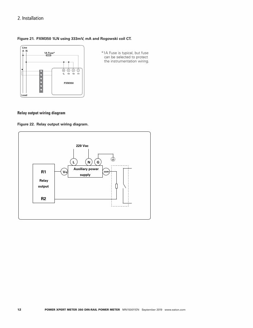
Figure 21. PXM350 1LN using 333mV, mA and Rogowski coil CT.
Relay output wiring diagram
Figure 22. Relay output wiring diagram.
A NLine
1A Fuse*
VN V3 V2 V1
PXM350
Load
10 9 8 7
R1
R2
Relay output
V+
L
Auxiliary power
supply
GN
com
220 Vac
*1A Fuse is typical, but fuse can be selected to protect the instrumentation wiring.

13
2. Installation
Power XPert Meter 350 DIN-raIl Power Meter MN150011EN September 2019 www.eaton.com
Communication
The PXM350 supports Modbus-RTU and BACnet MSTP protocols through its built-in RS-485 port. The RS-485 terminals are denoted as 'A', 'B' and 'S'. 'A' is the positive differential terminal, 'B' is the negative differential terminal and 'S' is for connecting the shield of the shielded twisted pair cable.
The maximum distance of the cable should not exceed 1200 m. This distance should be shorter if more devices are connected to the same communication link or if using a higher baud rate.
If the master device does not have a RS-485 port but a RS-232 port then a RS-232-RS-485 converter should be utilized.
In order to improve communication quality, use the following:
• A high-quality shielded twisted pair cable is very important, AWG22 (0.6 mm2) or lower is recommended.
• Pay attention to "single point earthing". This means that there is only one side for the shield to be connected to the ground in a communication link.
• Every A (+) should be connected to A (+), B (-) to B (-), or it will influence the network, even damage the communication interface.
• “T” type connection topology should be avoided. This means no new branches except from the starting point.
• Keep communication cables away as far as possible from sources of electrical noise. When several devices are connected in daisy chain to the same long communication line, a resistor (typical value 120- 300 Ohm, 0.25W) should be used at the end of the circuit (the last device of the chain).
• Use RS-232/RS-485 or USB/RS-485 converter with optical isolated output and surge protection.

14
3. Operation and application
Power XPert Meter 350 DIN-raIl Power Meter MN150011EN September 2019 www.eaton.com
3. Operation and applicationIn this chapter, users will be introduced to the interface of the meter as well as how to inter-act with the meter using the key on the display to read and configure parameters.
3.1 Display panel and keysThe PXM350MA6x2x meter consists of a built-in LCD screen and a key (SCROLL key) for users to interact with the meter. Figure 23 shows the display of the PXM350MA6x2x with all characters and number segments visible as a visual example only, they would not appear on one page. These symbols are explained in Table 1.
Figure 23. PXM350MA6x2x display.
Table 1. Display icons.
No. Content Description
1 Description area To display what kind of parameter in the display area. To distinguish between, split phase, current, demand, parameter settings, and so on.
2 Measurement parameter display area 7 segments can be displayed.
To display the main measurement parameters: energy, voltage, current, power, frequency, demand, settings, time.
3 Indicates all information mode.
4 Communication icon No icon: no communication;One icon: query sent;Two icons: query sent and response received.
5 Load size icon Displays analog representation of load magnitude.
6 Four- quadrant reactive power display Indicates the first to fourth quadrant reactive power.
7 Import icon(right arrow): displays the energy consumed. Export icon(left arrow) displays the energy generated.
8 Load type Inductance icon: inductive load capacitor icon: capacitive load
9 Unit Unit of the parameter being displayed.
1
2
3
4 5 6 7 8 9

15
3. Operation and application
Power XPert Meter 350 DIN-raIl Power Meter MN150011EN September 2019 www.eaton.com
3.2 Display mode and key operationsThe LCD display of the PXM350 meter consists of three display modes:
• Important parameter display
• All parameters display
• Settings mode.
By default, the important parameter display shows the consumed active energy (kWh) parameter.
Important parameter display mode:
The important parameter display mode is the default display mode of the meter. It will display the measurement parameters of the PXM350 series meter. Users only see the consumed active energy (kWh) parameter unless additional parameters are added through the settings mode.
Users will be in this mode when they power on the meter or when they push the “SCROLL” key after a period of inactivity. Each measurement parameter in this mode will display on the screen for six seconds. When the “SCROLL” key is pressed in this display mode it will lock the current page for a minute and the backlight will remain on. Pressing the “SCROLL” key again will turn the next page and lock the display for another minute. After one minute of inactivity the display will continue operating normally by cycling through the enabled measurement parameters.
All parameter display mode:
The all parameters display will show all the parameters that the PXM350 meter supports as well as information about the meter. Pressing and holding the “SCROLL” key from the important parameter display mode will direct the user to the all parameter display mode. In this mode there will be a displayed on the bottom row of the display to indicate the PXM350 is in all parameters display mode.
Pressing the "SCROLL" key will turn to the next page in the display. Once the user has cycled through all the parameters, pressing the "SCROLL" key again will take the user back to the first page.

16
3. Operation and application
Power XPert Meter 350 DIN-raIl Power Meter MN150011EN September 2019 www.eaton.com
3.3 Parameter display and key operationsThe following tables show the all parameters display for the different PXM350 series meters.
Table 2. All parameters display for PXM350MA6x2x.
Page Parameter
1 Voltage wiring check2 Current wiring check
3 Device address
4 Baud rate
5 Parity
6 Hardware version
7 Software version
8 Release date
9 Model
10 Consumed active energy(kWh)
11 Consumed active energy phase A(kWh)
12 Consumed active energy phase B(kWh)
13 Consumed active energy phase C(kWh)
14 Phase A voltage(V)
15 Phase B voltage(V)
16 Phase C voltage(V)
17 Phase A current(A)
18 Phase B current(A)
19 Phase C current(A)
20 Total current(A)
21 System active power(kW)
22 Active power phase A(kW)
23 Active power phase B(kW)
24 Active power phase C(kW)
25 Frequency(Hz)
26 Temperature
27 Meter run time
28 Load run time
--- End

17
3. Operation and application
Power XPert Meter 350 DIN-raIl Power Meter MN150011EN September 2019 www.eaton.com
Table 3. All parameters display for PXM350MA6x4x.
Page Parameter
1 Voltage wiring check2 Current wiring check3 Device address4 Baud rate5 Parity6 Hardware version7 Software version8 Release date9 Model10 Consumed active energy(kWh)11 Consumed active energy phase A(kWh)12 Consumed active energy phase B(kWh)13 Consumed active energy phase C(kWh)14 Phase A voltage(V)15 Phase B voltage(V)16 Phase C voltage(V)17 Phase A current(A)18 Phase B current(A)19 Phase C current(A)20 Total current(A)21 System active power(kW)22 Active power phase A(kW)23 Active power phase B(kW)24 Active power phase C(kW)25 Frequency(Hz)26 Temperature27 Meter run time28 Load run time--- End
3.4 Settings and operations:Settings mode
The settings mode is where the user can perform most configurations for the PXM350 meter. To enter the settings press the “SET” key which is located under the meters terminal cover. Next the user will be prompted by a password screen.
To input the user password, users will use the “SCROLL” key to change the value of the flashing digit. The “SET” key is used to move between digits and to confirm the entered password when on the last digit.
After entering the correct password, the PXM350 will direct users to the device address configuration of the meter.
ote:N Users will be redirected back to the important parameters screen after entering the password if the physical/electronic seal is enabled.
In the setting mode there will be an “S” in the top row followed by the setting page number. After a minute of inactivity in this mode, the meter will be redirected back to the important parameter display. If the “SCROLL” key is pressed and held, the meter will also be redi-rected out of the settings mode.
ote:N The default password of the meter is 0000.
ote:N The ‘SET’ key is located under the meters terminal cover.

18
3. Operation and application
Power XPert Meter 350 DIN-raIl Power Meter MN150011EN September 2019 www.eaton.com
In the settings mode, the following operations apply for the keys:
• The “SET” key is used to enter edit mode of the setting and to confirm the setting change.
• The “SCROLL” key is used to move to the next setting page and to change the value of the setting when in edit mode.
The following tables will show the setting display for the different PXM350 series meters.
Table 4. Setting display for PXM350MA6x2x.
Page Parameter range
1 Device address 1-247
2 Baud rate 1200;2400;4800;9600;19200;38400
3 Parity Even, odd, none2, none1
4 Energy pulse output P: real energy; Q:reactive energy
5 Reactive power calculation 0:true (Fundamental only); 1:generalized (includes current distortion power)
6 Password 0000-9999
7 Real-time reading mode 1: primary; 2: secondary
8 Wiring configuration 3LN; 1LN; 1LL;2LL
9 CT2 5A/1A(5A current input) 80mA/100mA/200mA(mA current input)
10 CT1 1~50,000
11 PT2 50~400
12 PT1 50~1000000
13 Pulse constant 1~60000
14 Pulse width 20~100ms
15 Energy decimal places 0-3
16 Custom data display: add
17 Custom data display: remove
18 Wiring check enable On; off
19
3. Operation and application
Power XPert Meter 350 DIN-raIl Power Meter MN150011EN September 2019 www.eaton.com
3.5 Meter configurationInitial setup
The PXM350 series meters need to be configured correctly in order for it to measure data accurately.
For the initial meter setup, the wiring mode, PT and CT ratios need to be configured on the meter. Here are the steps to set these up from the meter display. Install terminal cover with hole for "set" button as lower terminal cover if tamper detection is not required. To protect against access to set button when sealed, be sure to use the terminal cover without a hole as the lower terminal cover.
• Once the terminal cover is removed, press the “SET” key to enter the settings mode.
• Users will then be prompted by a password screen. You can leave the password as its default value of “0000” if no password was previously configured. If a password was configured use the “SCROLL” and “SET” keys to enter in the password.
• The next screen that will appear is the “S-0-1 Addr”
• Press the “SCROLL” key until you get to the “S-08 Lt” screen(S-04 if PXM350MA6x1x). Select the correct voltage wiring mode. This will be based on your voltage connection. For example if your voltage connection is a three phase 4 wire connection, the correct voltage wiring mode would be 3LN.
• Press “SET” to enter edit mode.
• Press “SCROLL” to select the wiring mode.
• Press “SET” to confirm the setting.
ote:N Refer to Section 2.3 Wiring for more details about wiring configurations.
• Press the “SCROLL” key to move to the CT2 page. This setting should already be config-ured to the secondary value of the Current sensor. After this is confirmed, press the “SCROLL” key to move to the next page.
• The ensuing page will be “S-10” for setting the primary rating of the Current sensor. If no Current sensor's are being used, leave this as the default value and press “SCROLL” to move to the next page. If Current sensor’s are being used, enter in the primary rating of the Current sensor here.
• Press “SET” to enter the edit mode and to move to the next digit.
• Press “SCROLL” to change the value of the digit.
• Press “SET” to confirm the setting and move to the next page.
• The next page will correspond to the PT2 setting. If no PT’s are being used, leave this setting as the default and press the “SCROLL” key to go to the next page. If you are using PT’s, enter the secondary value of the PT here.
• Press “SET” to enter the edit mode and to move to the next digit.
• Press “SCROLL” to change the value of the digit.
• Press “SET” to confirm the setting and move to the next page.
• The next page will be “S-12” for the primary rating of the PT if it is being used.
• Press the “SET” key to enter edit mode and to move to the next digit.
• Press the “SCROLL” key to change the value of the digit.
• Press the “SET” key to confirm the setting and move to the next page.
Once all of the initial meter configurations are set, the meter should now begin to read data correctly.

20
3. Operation and application
Power XPert Meter 350 DIN-raIl Power Meter MN150011EN September 2019 www.eaton.com
3.6 Energy pulse outputThe PXM350 series supports the transmission of energy pulses through the P1 and P2 terminals of the meter. The PXM350 series uses the KYZ output to transmit test pulses that are proportional to the accumulated energy that the meter is measuring.
The maximum output voltage and current of the pulse output circuit in the PXM350 series is 250 V and 100 mA respectively.
Configuration
Ensure that the following configurations in the meter are correct to make certain the accu-racy of the meter.
• Wiring mode
• CT2
• CT1
• PT2
• PT1
To check these settings refer to section 3.5 in the meter configurations section of the manual.
With the above settings confirmed to ensure the meter will measure the voltage and current accurately, the next step is to configure the meter to output the desired number of pulses based on the required specification.
Make certain that you are in the settings mode. To get into the settings mode follow the procedure in section 3.5 of the manual.
• Once in the “Settings” mode, press the “SET” key to get to the “S-04 PULSE” page. This configuration is to enable the meter to output pulses based on the active energy (P) or the reactive energy (Q).
• Press the “SET” key to modify the setting; the cursor should now flash.
• Press the “SCROLL” key to select the type of energy to output.
• Press the “SET” key to confirm the selection.
• Press the “SCROLL” key to get to the “S-13 Pn” page. This configuration will represent the number of pulses (pulse constant) the meter will output per kWh/kvarh. This will be based on the required specification.
• Press the “SET” key to modify; the first digit will begin to flash.
• Press the “SET” key to move to the next flashing digit.
• Press the “SCROLL” key to change the flashing digit’s number.
• Press the “SET” key on the last digit to confirm all the changes after they have been made.
The following calculations can be used in order to calculate the value in the meter for the DO pulse constant:
• First you will need to determine how many pulses are needed to represent 1 kWh or how many kWh will represent 1 pulse.
• In this procedure, we will assume that 1 pulse = 10kWh is what is needed. Then follow these steps:
• Multiply the PT ratio and CT ratio i.e. PT1/PT2 * CT1/CT2.
Example: PT ratio of 6600V/120V, CT ratio of 2000:5A => 6600/120 * 2000/5 = 22,000.
ote:N if no PTS were used, then enter the PT ratio as the default on the meter, i.e. 400/400. If the CT2: 333mV, Rogowski Coil or 80/100/200mA, consider this a 1A for the

21
3. Operation and application
Power XPert Meter 350 DIN-raIl Power Meter MN150011EN September 2019 www.eaton.com
calculation.
• Divide 10kWh by 22,000 i.e. (10/22000) kWh = (1/2200) kWh.
• This means that 1 pulse = (1/2200)kWh, therefore 2200 pulses = 1kWh
• Since we get 2200 pulse/kWh, enter 2200 as the pulse constant into the meter
• Press “SCROLL” to get to the “S-14 PH” page. This configuration will represent the pulse width of the pulse that the meter will output. Put in the pulse width for the pulse output. The range is 20-100ms.
Figure 24. Pulse output wiring diagram.
Pulse output wiring
• A 24V DC supply is required to power the circuit and should be connected to the P2 terminal of the meter.
• A 1 kilo ohm resistor is suggested to be used in series to limit the current to the P2 termi-nal (refer to figure 24 above).
• The P1 terminal is connected to the positive terminal of the pulse counter.
• The negative terminal of the 24V DC supply is connected to the negative of the pulse counter.
With the pulse output circuit and settings configured the pulse output can be tested. Inject the meter with both voltage and current to ensure that the meter will accumulate energy and also output the pulses based on the above settings.
-Pulse counter
+Pulse counter
P2
P1
1kΩ
24V supply
+ -

22
4 Functions functions and software
Power XPert Meter 350 DIN-raIl Power Meter MN150011EN September 2019 www.eaton.com
4 Functions functions and softwareThis chapter will introduce you to using some important functions. Many advanced func-tions cannot be performed through the meter's display. Modbus communication is needed to connect to the software. This chapter will introduce you to some of the software’s functions.
4.1 Introduction to PXM350 utility softwareThe PXM350 series meters can be accessed through the PXM350 utility software. The soft-ware can be downloaded from the Eaton website under Downloads, or using the following link:
www.eaton.com/pxm
The software can be used to read the meters measurements or to configure the meters settings. To connect to the software a USB-RS-485 converter must be used.
ote:N The PXM350 utility software is a Windows based software.
The following details the steps to connect the meter to the computer with the USB-RS-485 converter.
To connect the following two wires should be connected from the USB-RS-485 converter to the meter:
1) T/R+ from the converter to “A” on the PXM350 series meter
2) T/R- from the converter to “B” on the PXM350 series meter
The following figure shows the two wire connections.
Figure 25. 1 Connecting USB-RS-485 converter to PXM350 series meter.
The Communication port (COM port) that the meter is connected to on the computer can be found from the “Device Manager” in Windows.
Use the following steps to get to the device manager on your Windows computer:
1. Open the Windows start menu.
2. Right click on computer and select properties.
3. In the window that appears, select device manager from the left navigation panel.
4. In the device manager window, double click on ports (COM&LPT) from the dropdown list.
5. Locate the USB serial port (COMx) information where the x is the port number to use. For example COM3.
T/R+ T/R- RXD+ RXD-
RS485-to-USB converter
GND VCC
A
B
S
Power meter
Co
mm
po
rt

23
4 Functions functions and software
Power XPert Meter 350 DIN-raIl Power Meter MN150011EN September 2019 www.eaton.com
Once the COM port is found make note of it as it is used to connect to the software
Once the software has been opened, users will be prompted to enter the correct COM port of the computer, baud rate, parity, the device address of the meter, and the device type (PXM350MA6x2x, PXM350MA6x4x). Enter the settings and click ‘OK’ to connect the meter to the software.
ote:N The baud rate, parity, and device address must be the same on the meter as well as the PXM utility software.
The following figure shows the screen when you first open PXM350 utility software.
Figure 26. Initial screen.

24
4 Functions functions and software
Power XPert Meter 350 DIN-raIl Power Meter MN150011EN September 2019 www.eaton.com
4.2 Parameter settingsThe PXM350 series meters requires general settings so that the meters can work according to the correct specification. The general settings can be found by clicking on the “Settings” menu on the main menu toolbar and selecting “General Settings” on the top menu bar of the software. The figure below shows the General Settings.
Figure 27. General settings in the PXM350 utility software.
ote:N To ensure that any modifications in the general settings takes place you must click on “Update Device” on the bottom of the general settings page.
Wiring method and CT/PT settings
Users will need to select the correct “Wiring Method” (refer to section 2.3 for details). Users will also need to set the PT and CT ratio according to the practical use, if not set correctly this can lead to inaccurate measurements. “CT1” is the rated input of the CT being used, and “PT1” and “PT2” correspond to the PT ratio of the PT used. The following figure shows these mentioned settings in the red boxes.

25
4 Functions functions and software
Power XPert Meter 350 DIN-raIl Power Meter MN150011EN September 2019 www.eaton.com
Figure 28. The wiring method and CT/PT settings in the general settings.
Reactive power calculation:
Real reactive:
Generally reactive:
Modbus communication options:
At the very top of the general settings page users can configure the meters address, baud rate and parity for communication with the meter through Modbus. The red box in figure 29 shows how it is displayed in the PXM350 utility software.
Figure 29. Meter address, baud rate, and meter parity settings on PXM350 utility software.
Energy pulse output
The PXM350 series supports the transmission of the pulses through the P1 and P2 termi-nals of the meter.
Active: P1, P2 terminal output pulse is based on the active energy pulse.
Reactive: the output pulse is based on the reactive power pulse.
You can see in the red box of the following figure the configuration for the energy pulse output.
Q S P D� � �( )2 2 2
Q S P� �( )2 2

26
4 Functions functions and software
Power XPert Meter 350 DIN-raIl Power Meter MN150011EN September 2019 www.eaton.com
Figure 30. The energy pulse output in the general settings.
The user will also have to enter the requirements for the pulse in the “Pulse Constant” and “Pulse Width” fields. The “Pulse Constant” is the number of pulses the user needs one pulse to represent in kWh/kvarh. The user can enter a value from 1-60000 for the pulse constant. The “Pulse Width” of the pulse is the duration it will last for. The user can enter a value from 20-100ms in this field. The figure below shows this in the red box.
Figure 31. The pulse constant and pulse width in the general settings.
Demand
Demand supports four kinds of calculation modes:
• Sliding block method Set a 1-30min window time, which is the calculation time of demand. The window slides once per minute and updates the demand value at this time.
• Fixed block method Set 1-30min as a demand calculation cycle. The whole cycle calculates the demand once. This means that the demand update time is equal to the demand calculation cycle.
• Rolling block method Set 1-30min as a demand calculation cycle and 1 slip time. The demand cycle must be integer multiples of the slip time. It calculates 1 cycle’s demand at the end of the slip time. The demand update time is equal to the slip time.
• Thermal demand method Set 1-30min as a calculation cycle. In the whole cycle, the demand is calculated just once. This means that the demand update time is equal to the demand calculation cycle.
You can see the demand calculations in the red box of the following figure. Under the dropdown menu in “Compute Mode” is where you can find the four different methods mentioned above.

27
4 Functions functions and software
Power XPert Meter 350 DIN-raIl Power Meter MN150011EN September 2019 www.eaton.com
Figure 32. The demand calculation modes in the general settings of PXM350 utility software.
To view the demand parameter display click on ‘Readings’ on the main menu toolbar and then select ‘Demand’. Figure 33 shows the demand display.
Figure 33. Demand parameters display.
Sealing option
• Choosing the “Device Clock + TOU related”, the corresponding content (device clock, TOU parameters, daylight saving time parameters) can be sealed.
• Choosing “Run-time and Load-time” the content of the run and load time will be sealed.
• Choosing “Communication” the content of communication time will be sealed.
ote:N To change the corresponding time it must occur once the seal is open.

28
4 Functions functions and software
Power XPert Meter 350 DIN-raIl Power Meter MN150011EN September 2019 www.eaton.com
The figure below shows the sealing options in the red box for the PXM350 utility software.
Figure 34. The sealing options in the general settings.
Communication permission
The communication permission is divided into two settings either “low permission” or “high permission”.
• Low permission: Is the important operations disabled. These operations include clear demand event record, programming event record, open cover event record, meter, energy data, and initial energy data.
• High permission: This setting supports all functions.
ote:N In the low permission you can update to high permission through updating the communication permission. After 30 minutes of updating to high permission, the meter would lower its permission to “low permission” automatically, to keep the meters safety.
The figure below shows the communication permission in the red box.
Figure 35. Communication permission in the general settings of the PXM350 utility software.
29
4 Functions functions and software
Power XPert Meter 350 DIN-raIl Power Meter MN150011EN September 2019 www.eaton.com
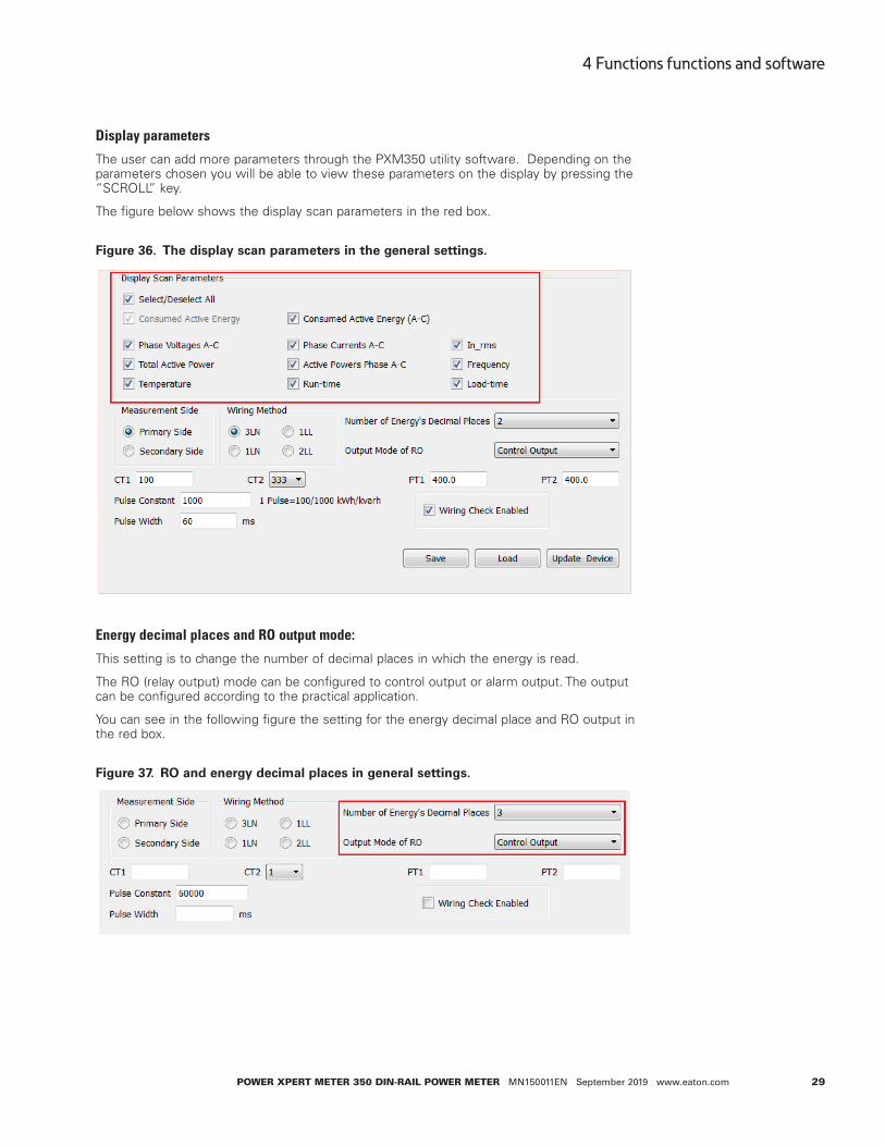
Display parameters
The user can add more parameters through the PXM350 utility software. Depending on the parameters chosen you will be able to view these parameters on the display by pressing the “SCROLL” key.
The figure below shows the display scan parameters in the red box.
Figure 36. The display scan parameters in the general settings.
Energy decimal places and RO output mode:
This setting is to change the number of decimal places in which the energy is read.
The RO (relay output) mode can be configured to control output or alarm output. The output can be configured according to the practical application.
You can see in the following figure the setting for the energy decimal place and RO output in the red box.
Figure 37. RO and energy decimal places in general settings.
30
4 Functions functions and software
Power XPert Meter 350 DIN-raIl Power Meter MN150011EN September 2019 www.eaton.com
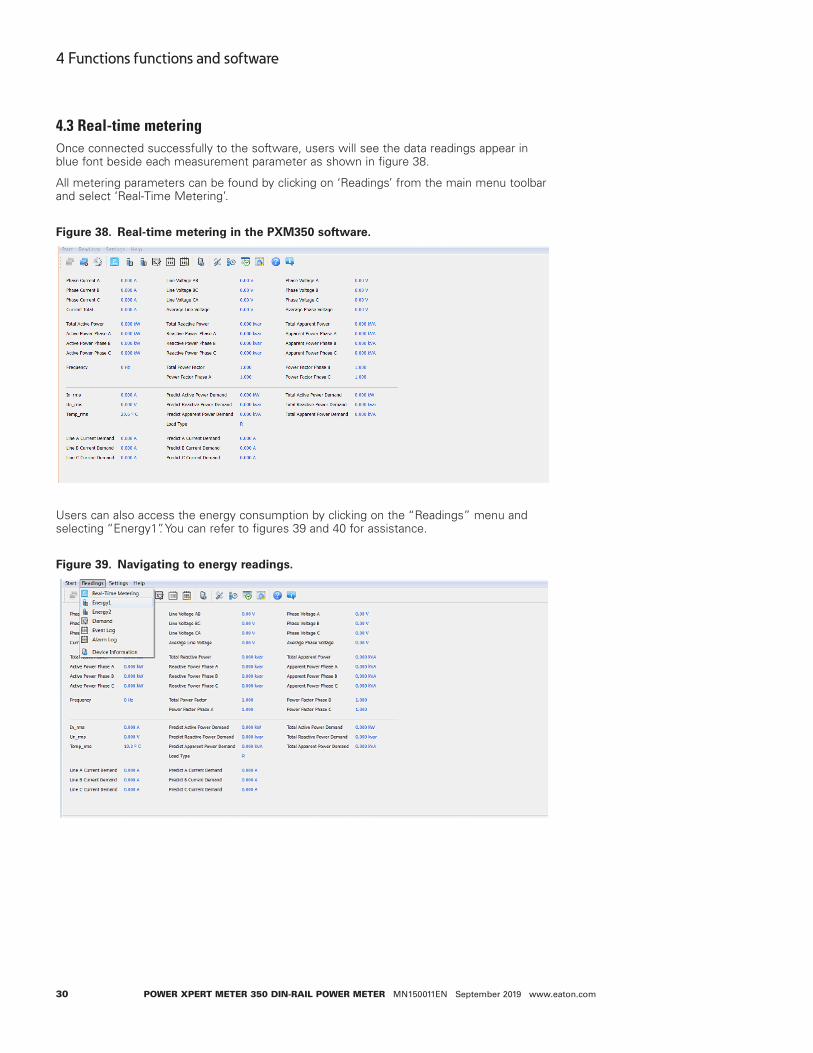
4.3 Real-time meteringOnce connected successfully to the software, users will see the data readings appear in blue font beside each measurement parameter as shown in figure 38.
All metering parameters can be found by clicking on ‘Readings’ from the main menu toolbar and select ‘Real-Time Metering’.
Figure 38. Real-time metering in the PXM350 software.
Users can also access the energy consumption by clicking on the “Readings” menu and selecting “Energy1”. You can refer to figures 39 and 40 for assistance.
Figure 39. Navigating to energy readings.

31
4 Functions functions and software
Power XPert Meter 350 DIN-raIl Power Meter MN150011EN September 2019 www.eaton.com
Figure 40. Energy readings page.
Users will see all the energy that the meter has accumulated since the life of the meter or since the last time the energy readings were reset or cleared.
The lower half of the energy1 page displays the consumed active energy readings that have been accumulated under the time of use (TOU) function of the meter.
ote:N The time of use (TOU) function is only available on the PXM350MA6x2x, and PXM350MA6x4x models.
With the time of use function users can select the time period of the TOU energy as the current month, previous month or the past two months.
Users can also provide initial values for their PXM350 series models to start to accumulate energy from. To do this, users must have sufficient permission, which can be obtained from the general settings page.
4.4 Measurement functionPXM350 series provides measurement of bi-directional energy accumulation. Real time energy can be initialized by changing the permission and sealing condition. The energy parameters supported:
Consumed active energy
Generated active energy
Total active energy
Net active energy
Consumed apparent energy
Generated apparent energy
Four-quadrant reactive energy
Consumed reactive energy
Generated reactive energy
Total reactive energy
Net reactive energy
These parameters can be located on the energy 2 readings page, which can be found on the ‘Readings’ menu and selecting ‘Energy 2’. Figure 41 shows how this will look on the PXM350 utility software.

32
4 Functions functions and software
Power XPert Meter 350 DIN-raIl Power Meter MN150011EN September 2019 www.eaton.com
Figure 41. Energy 2 readings page.
TOU settings
Users can assign up to four different tariffs (sharp, peak, valley and normal) to different time periods within the day according to the billing requirements.
The meter will calculate and accumulate energy in different tariffs according to the meters internal clock timing and TOU settings.
The following figure shows the time of use setting display page.
Figure 42. Time of use settings page.

33
4 Functions functions and software
Power XPert Meter 350 DIN-raIl Power Meter MN150011EN September 2019 www.eaton.com
TOU schedules can be configured up to 14 time segments, where each season can have its own TOU schedule. The user can customize the TOU calendar (including its tariffs, seasons, schedules and segments) according to different applications. To make sure that the TOU calendar is setup correctly, the meter will check the TOU settings according to the predefined rules (see below for “TOU Parameter Settings” for details). The TOU function will be disabled if the TOU calendar is set up incorrectly. If no errors are found in the calendar and the TOU function is enabled, TOU energy accumulation will commence.
TOU parameter settings:
a. Season settings: the maximum number of seasons is 14, where each season can have its own TOU schedule. Note: The seasons should be entered as an integer from 1-14 and should also be entered in chronological order.
b. Schedule settings: You can have a maximum of 8 schedules, where each schedule can be divided up into 14 time segments.
c. Segment settings: You can have a maximum of 14 segments, where each segment can have its own tariff.
d. Tariff setting: There is a maximum of 4 tariffs. The four tariffs are sharp, peak, valley, and normal. They are represented by number 1-4 respectively (1: sharp, 2: peak, 3: valley, 4: normal). If the parameter is set as 2 then only the first 2 tariffs (sharp and peak) will be available.
e. Weekend settings: In this section you can set up the schedule number according to weekends to assign a weekend schedule. Refer to figure 43.
Figure 43. Weekend setting in TOU configurations page.
f. Holiday setting: You can set up to a maximum of 30 holidays.
ote:N If the holiday and weekend schedule number is set as 0, it means holidays are unavailable. If the weekend and holidays are overlapped, the holiday overrides the weekend settings since the holiday has a higher priority.
TOU seasons
Fill in the appropriate slots in the TOU (time of use) seasons based on the number in the “Season Settings”. If the “Season Settings” is set to 2 then only the first 2 slots of the “TOU Seasons” must be filled in.
ote:N If the slot is filled inappropriately then the TOU function will be disabled
• The start date into the TOU Season slot is in the following format: “MM-DD-ID”
• MM stands for month
• DD stands for date
• ID represents the TOU schedule (1-8)
ote:N The dates should be organized in chronological order (The earliest date comes first and the later date follows). Entering the dates in the wrong order will cause the TOU function to be disabled

34
4 Functions functions and software
Power XPert Meter 350 DIN-raIl Power Meter MN150011EN September 2019 www.eaton.com
Holidays
Fill in the appropriate slots under the “Holidays” setting based on the number in the “Holiday Setting”. If the “Holiday Setting” is set as 3 then only the first 3 slots of the “Holidays” must be filled in otherwise the TOU function will be disabled.
• Enter the date of the holiday in the holiday schedule slot in the following format “MM-DD-ID”
• MM stands for month
• DD stands for date
• ID represents the TOU schedule(1-4)
ote:N The dates of the holiday schedules do not need to be organized in chronological order.
TOU schedules
Each TOU schedule is represented by a 24 hour cycle. Fill in the appropriate slots in the TOU schedule based on the number in the “Schedule Settings”. If the “Schedule Setting” is set as 8 then all of the “TOU Schedules” must be filled in.
The amount of slots to fill in each TOU schedule depends on the “Segment Setting” param-eter. If the “Segment Setting” parameter is set as 3 then the first 3 slots in each TOU schedule must be set, otherwise the TOU function will be disabled.
• Enter the start time into the TOU schedule slot in the following format “HH-MM-ID”
• HH stands for hour in 24 hour format
• MM stands for minutes
• ID represents the tariff to follow (1-8)
The time should be organized in chronological order (The earliest time comes first and the later time follows).
ote:N Entering the time in the wrong order will cause the TOU function to be disabled
Daylight saving time (DST)
There are two types of formats that the daylight savings time can be enabled as:
1. Fixed date option:If you choose a fixed date option, you set the format according to a fixed date for the DST switch, in the format of month/ day/ hour/ minute/ adjust time (in minutes).
2. Non-fixed date option: If you choose the non-fixed option, the DST will be implemented by which day of the week, with the format as month/ which day/ which week/ hour/ minute/ adjust time (in minutes).
Setting the DST will cause the meter to automatically switch to and from daylight savings time. When the clock starts to run on daylight saving time, the meter will automatically adjust its clock to a time period in advance. While the clock is running to the end of daylight saving the meter will adjust its clock back to a pervious time period.
ote:N Make sure to click “Update Device” after making any changes in order to save the settings. If no errors are found then the TOU energy accumulation will begin.
35
4 Functions functions and software
Power XPert Meter 350 DIN-raIl Power Meter MN150011EN September 2019 www.eaton.com
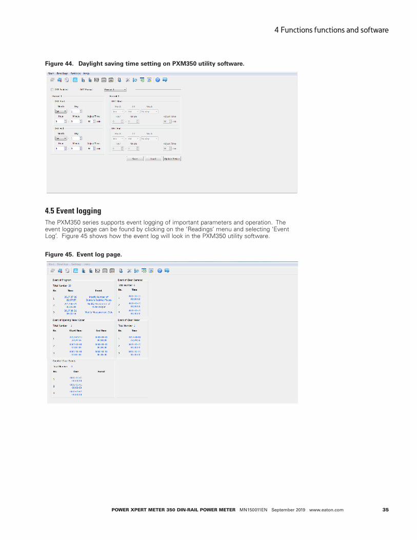
Figure 44. Daylight saving time setting on PXM350 utility software.
4.5 Event logging The PXM350 series supports event logging of important parameters and operation. The event logging page can be found by clicking on the ‘Readings’ menu and selecting ‘Event Log’. Figure 45 shows how the event log will look in the PXM350 utility software.
Figure 45. Event log page.

36
4 Functions functions and software
Power XPert Meter 350 DIN-raIl Power Meter MN150011EN September 2019 www.eaton.com
The events that are logged include:
• Event of program
This event records the programming time and programming event. When a programming event occurs several times within 5 minutes, the meter only records the first time.
Table 5. Programming flags and events.
Programming flag Programming event
01 Meter address programming event02 RS-485 communication programming event03 Reserved04 Reserved05 Energy pulse programming event06 Demand related programming event07 Reactive calculation method programming event08 VAR/PF statue programming event09 Change time programming event100 Change energy base programming event101 TOU parameter programming event102 Daylight saving time programming event103 Trend record programming event
Figure 46. Programming event log in PXM350 utility software.

37
4 Functions functions and software
Power XPert Meter 350 DIN-raIl Power Meter MN150011EN September 2019 www.eaton.com
• Event of clear demand
The meter will record when the demand parameters are cleared. It records up to 3 groups of clear demand events.
Figure 47. Event of opening meter cover in PXM350 utility software.
• Event of clear meter In the event of clear meter, it shows when the meter has had any data cleared. It supports three groups of meter clearance events.
Figure 48. Event of clear meter.
4.6 Alarm functionThe alarm function is used to monitor specific parameters, and when these parameters exceed a certain preset time limit, the event alarm will be triggered and stored in the PXM350 utility software. There can be a maximum of 20 records stored in the alarm log.
To access the alarm settings click on “Settings” from the toolbar menu and then select “Alarm Settings”.
To set up the alarms, users must first select an alarming parameter, a condition, a delay time (ms), and an alarming output. Users can set a maximum of 12 alarms. Figure 49 shows you the Alarm Settings.

38
4 Functions functions and software
Power XPert Meter 350 DIN-raIl Power Meter MN150011EN September 2019 www.eaton.com
Figure 49. Alarm settings page on PXM350 utility software.
Configuring the alarm
• Enable the alarm function by checking off the “Alarm Enabled” box.
• Enable the preferred alarm channel(s) by checking off the “Alarm Enabled” box next to the channel.
• Under the “Alarm Channel” column select the parameter from the real-time metering.
• Choose the required setting or condition for the alarm i.e. greater than (>), equal to (=), or less than (<).
• Enter the set point, where the set point is expressed by a percentage of the rated value. The rated value for current or voltage corresponds to the primary sensor setting. The rated value for power is based on product of current and voltage primary ratings.
• Enter in the desired delay (ms) before alarm is triggered.
• Select the “Output Enabled” box if using a RO channel to be triggered when an alarm event occurs.
ote:N Make sure to click on “Update Device” after making any changes in order to save the settings to the meter.

39
4 Functions functions and software
Power XPert Meter 350 DIN-raIl Power Meter MN150011EN September 2019 www.eaton.com
Reading the alarm
To read the alarm log on the PXM350 series utility software you click on the ‘Readings’ menu and select ‘Alarm Log’. The alarm log can be seen in figure 50.
Figure 50. Alarm log on PXM350 series utility software.
Referring to figure 50, we can see that the alarm log features the time stamp which provides the time and date the alarm was triggered. The log also identifies which parameter was triggered (current, voltage, etc), and has a column for the value of break over which tells the user the amount they went over/under for that particular alarm setting. The last column of the alarm log is the status column. The alarm log can store up to 20 groups of alarm events.
4.7 Incorrect connection detectionThe PXM350 series meter has a connection detection function. This function detects the connections or wiring to the meter based on the wiring mode configuration.
Table 6. Connection Detection.Bit15 Bit14 Bit13 Bit12 Bit11 Bit10 Bit9 Bit8
Reserve Phase voltage A missing
Phase voltage B missing
Phase voltage C missing
Reserve Phase voltage A wrong connection
Phase voltage B wrong connection
Phase voltage C wrong connection
Bit7 Bit6 Bit5 Bit4 Bit3 Bit2 Bit1 Bit0
Reserve Phase current A wrong direction
Phase current B wrong direction
Phase current C wrong direction
Reserve Phase current A wrong connection
Phase current B wrong connection
Phase current C wrong connection
The very first screen in the all parameters display (see section 3.3 for details) is the voltage wiring check. On the LCD display, it will be in the following format:
U XXXXXX, where X is either ‘1’ or ‘0
• ‘0’ represents the connection is correct.
• ‘1’ represents the connection is incorrect.

40
4 Functions functions and software
Power XPert Meter 350 DIN-raIl Power Meter MN150011EN September 2019 www.eaton.com
On the meter display digits 1~3 (from left to right) are would represent if a phase is not connected; Phase A voltage missing, Phase B voltage missing, Phase C voltage missing. Digits 4~6 represent Phase A voltage, Phase B, Phase C voltage being connected incorrectly.
The second screen in the all parameters display (see section 3.3 for details) is the current wiring check. On the meter display, it will be in the following format:
I XXXXXX, where X is either ‘1’ or ‘0’
• ‘0’ represents the connection is correct.
• ‘1’ represents the connection is incorrect.
On the meter display digits 1~3 (from left to right) represent phase A CT, phase B CT, phase C CT being in the reverse direction . Digits 4~6 represent phase A CT, phase B CT, phase C CT being connected incorrectly.
4.8 Sealing functionThe PXM350 series meter supports a sealing function. When the seal is open, the read write functions are available. When the seal is closed some of the meters functions which include parameters and optional parameters will be blocked and limited. These parameters can still be accessed by keys communication, but cannot be modified (Write function not available when seal is closed) when sealed status is present.
Address 209H corresponds to parameters blocked by the seal, which can be configured by users through communication. These settings will be valid only when the seal is in sealed status.
From 101H, we can check if the sealing state is opened or closed. When the seal status is open the address displays open sealing state. When the seal status is closed, the address displays closed sealing state, and the corresponding content will be blocked.
ote:N ‘X’ means that these addresses will be blocked for keys and communication, and ‘- ‘means this function is unavailable.
Seal standard content:
Table 7. Seal standard content.address Parameter description Communication Key
203H Pulse quantity choice X X204H Demand calculation X -
205H Demand calculation cycle X -206H Slip time demand calculation X -207H Reactive power calculation method X X208H VAR/PF convention X -209H Seal optional content X -213H Remove electric meter data (except demand data) X -216H Measurement side X X217H Wiring mode X X218H CT2 X X219H CT1 X X220H PT2 X X222H~223H PT1 X X224H Pulse constant X X225H Pulse width X X226H Energy decimal places X X

41
4 Functions functions and software
Power XPert Meter 350 DIN-raIl Power Meter MN150011EN September 2019 www.eaton.com
Energy:
Table 8. Energy data.Modbus address (HeX) Parameter description Communication Key
900H-901H total active energy X -
902H-903H Total active energy tariff 1 X -904H-905H Total active energy tariff 2 X -906H-907H Total active energy tariff 3 X -908H-909H Total active energy tariff 4 X -91AH-90BH Net active energy X -90CH-90DH Net active energy tariff 1 X -90EH-90FH Net active energy tariff 2 X -910H-911H Net active energy tariff 3 X -912H-913H Net active energy tariff 4 X -914H-915H Import active energy X -916H-917H Import active energy tariff 1 X -918H-919H Import active energy tariff 2 X -91AH-91BH Import active energy tariff 3 X -91CH-91DH Import active energy tariff 4 X -91EH-91FH Export active energy X -920H-921H Export active energy tariff 1 X -922H-923H Export active energy tariff 2 X -924H-925H Export active energy tariff 3 X -926H-927H Export active energy tariff 4 X -928H-929H Total reactive energy X -92AH-92BH Total reactive energy tariff 1 X -92CH-92DH Total reactive energy tariff 2 X -92EH-92FH Total reactive energy tariff 3 X -930H-931H Total reactive energy tariff 4 X -932H-933H Net reactive energy X -934H-935H Net reactive energy tariff 1 X -936H-937H Net reactive energy tariff 2 X -938H-939H Net reactive energy tariff 3 X -93AH-93BH Net reactive energy tariff 4 X -93CH-93DH Import reactive energy X -93EH-93FH Import reactive energy tariff 1 X -940H-941H Import reactive energy tariff 2 X -942H-943H Import reactive energy tariff 3 X -944H-945H Import reactive energy tariff 4 X -946H-947H Export reactive energy X -948H-949H Export reactive energy tariff 1 X -94AH-94BH Export reactive energy tariff 2 X -94CH-94DH Export reactive energy tariff 3 X -94EH-94FH Export reactive energy tariff 4 X -950H-951H Apparent energy X -
42
4 Functions functions and software
Power XPert Meter 350 DIN-raIl Power Meter MN150011EN September 2019 www.eaton.com
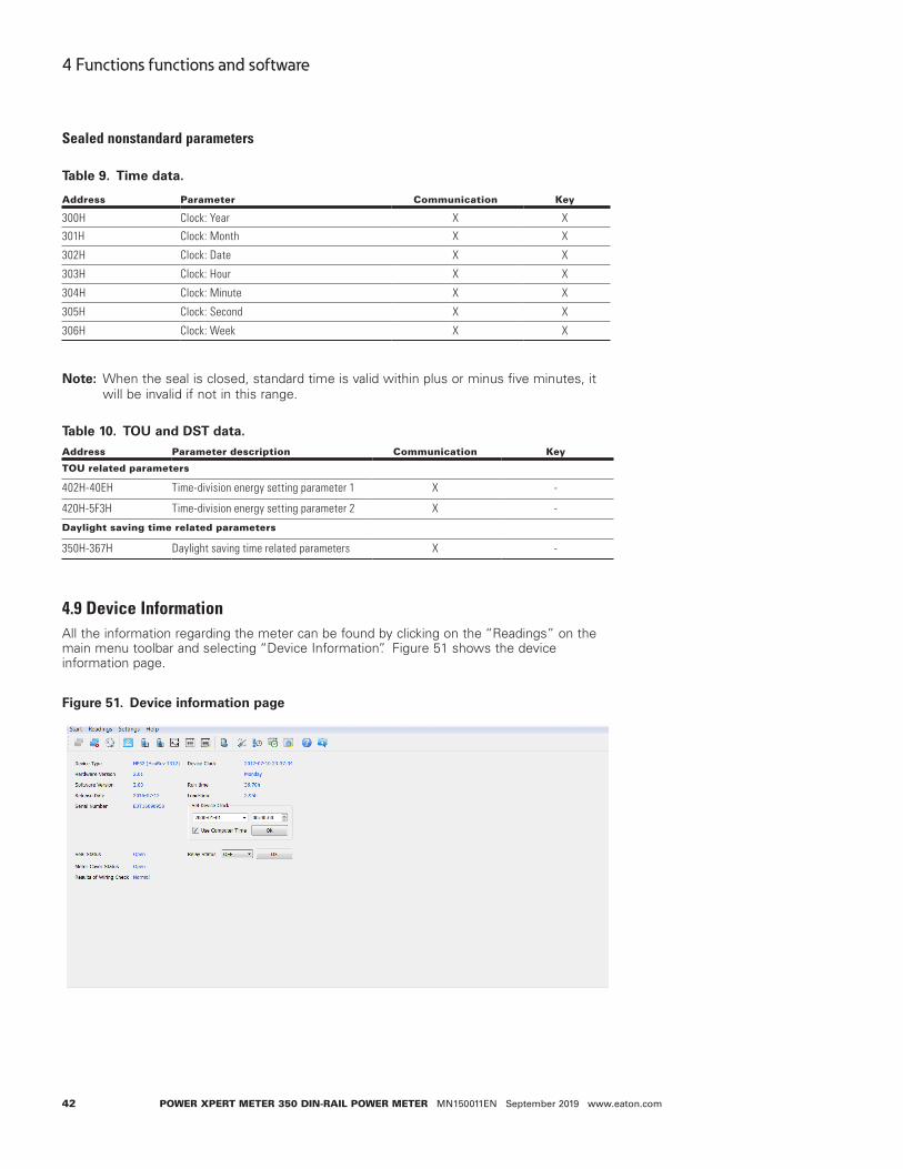
Sealed nonstandard parameters
Table 9. Time data.
address Parameter Communication Key
300H Clock: Year X X
301H Clock: Month X X
302H Clock: Date X X
303H Clock: Hour X X
304H Clock: Minute X X
305H Clock: Second X X
306H Clock: Week X X
ote:N When the seal is closed, standard time is valid within plus or minus five minutes, it will be invalid if not in this range.
Table 10. TOU and DST data.address Parameter description Communication Key
toU related parameters
402H-40EH Time-division energy setting parameter 1 X -
420H-5F3H Time-division energy setting parameter 2 X -
Daylight saving time related parameters
350H-367H Daylight saving time related parameters X -
4.9 Device InformationAll the information regarding the meter can be found by clicking on the “Readings” on the main menu toolbar and selecting “Device Information”. Figure 51 shows the device information page.
Figure 51. Device information page

43
4 Functions functions and software
Power XPert Meter 350 DIN-raIl Power Meter MN150011EN September 2019 www.eaton.com
Device information such as hardware and software version of the meter can be found on this page. The serial number and the seal status can also be located here. It is important to note that when the seal status is set to “Closed”, the user will not be able to make any configuration changes to the meter.
Users can also configure the device clock of the meter from this page to the time of the computer the meter is connected to or give it any other specific time.
44
5 Communication
Power XPert Meter 350 DIN-raIl Power Meter MN150011EN September 2019 www.eaton.com
5 CommunicationThis chapter introduces users on how to communicate with the PXM350 Series meter through the Modbus and BACnet MSTP communications protocols. Knowledge of the Modbus or BACnet communications protocols would be beneficial for users who read this chapter.
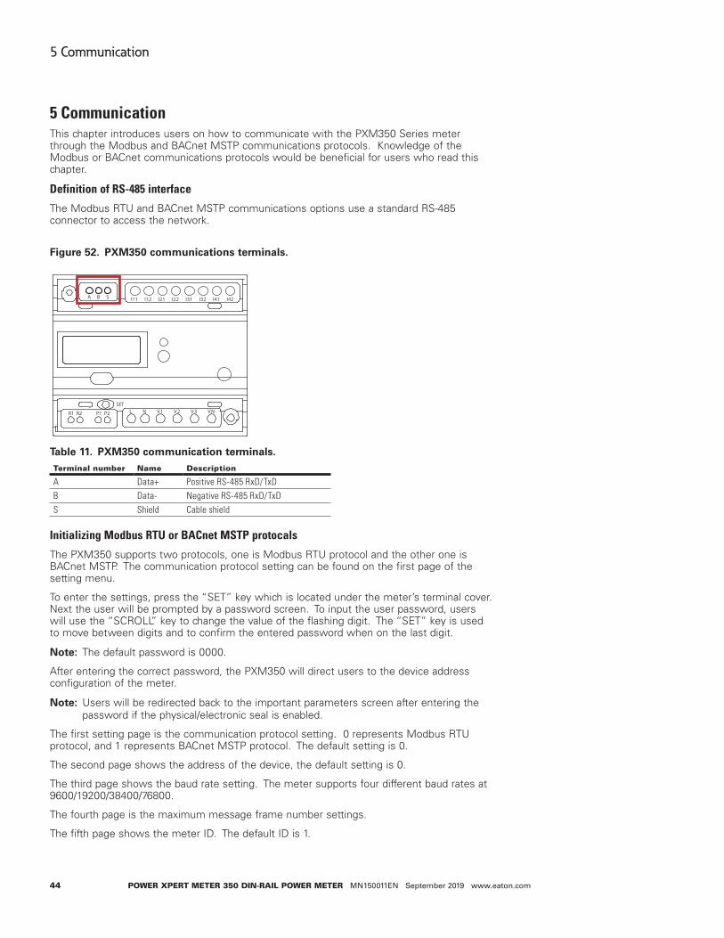
Definition of RS-485 interface
The Modbus RTU and BACnet MSTP communications options use a standard RS-485 connector to access the network.
Figure 52. PXM350 communications terminals.
Table 11. PXM350 communication terminals.terminal number Name Description
A Data+ Positive RS-485 RxD/TxDB Data- Negative RS-485 RxD/TxDS Shield Cable shield
Initializing Modbus RTU or BACnet MSTP protocals
The PXM350 supports two protocols, one is Modbus RTU protocol and the other one is BACnet MSTP. The communication protocol setting can be found on the first page of the setting menu.
To enter the settings, press the “SET” key which is located under the meter’s terminal cover. Next the user will be prompted by a password screen. To input the user password, users will use the “SCROLL” key to change the value of the flashing digit. The “SET” key is used to move between digits and to confirm the entered password when on the last digit.
ote:N The default password is 0000.
After entering the correct password, the PXM350 will direct users to the device address configuration of the meter.
ote:N Users will be redirected back to the important parameters screen after entering the password if the physical/electronic seal is enabled.
The first setting page is the communication protocol setting. 0 represents Modbus RTU protocol, and 1 represents BACnet MSTP protocol. The default setting is 0.
The second page shows the address of the device, the default setting is 0.
The third page shows the baud rate setting. The meter supports four different baud rates at 9600/19200/38400/76800.
The fourth page is the maximum message frame number settings.
The fifth page shows the meter ID. The default ID is 1.
A B S I11 I12 I21 I22 I31 I32 I41 I42
L N V1 V2 V3 VNR1 R2 P1 P2SET

45
5 Communication
Power XPert Meter 350 DIN-raIl Power Meter MN150011EN September 2019 www.eaton.com
The sixth page is the reset page. To reset the BACnet settings, change the value to 1 and press “SET” button to confirm.
ote:N Users need to reset the meter to save the settings after making any changes of BACnet settings.
5.1 Modbus protocol information5.1.1. Transmission mode
The mode of transmission defines the data structure within a frame and the rules used to transmit data.
• Coding system 8 bit
• Start bit 1 bit
• Data bits 8 bit
• Parity No parity/ odd parity/ even parity
• Stop bit 1 bit or 2 bit
• Error checking CRC
5.1.2. Frame
When the data frame reaches the PXM350 series meter (slave device), the meter removes the data frame’s header, and reads the data. If there is no error, then the meter will imple-ment the data’s task. Once the task is completed, the meter will put its own data with the acquired header and send back the frame to the master device that queried the meter. The response data frame contains the address, function, data and CRC check. An error will cause the response to fail.
Table 12. Data frame format.address Function Data Check
8-Bits 8-Bits N x 8-Bits 16-Bits
Address field
The address field is the data at the start of the frame. It is composed of 8 bits (1 byte) and corresponds to the device address. It has a decimal value ranging from 1-247.
The master device addresses the slave device by placing the slave device address in the address field of the message. When the slave sends its response, it places its own address in the address field of response to let the master know which slave is responding.
Function field
When a query is sent from the master to a slave device, the function code filed tells the slave what kind of action to perform.
Table 13. Function code.Function code Meaning action
03 read holding register obtain current value of 1 or more registers
16 Preset register Set value of 1 or more register
01 Reading relay RO status Get the current state of the relay of the RO output (ON/OFF)05 Control relay RO state Control relay RO output state (ON/OFF)

46
5 Communication
Power XPert Meter 350 DIN-raIl Power Meter MN150011EN September 2019 www.eaton.com
Data field
The data field contains the data that the slave device needs in order to complete the request. This data may be a numerical value, address or settings. For example, the function code tells the slave device to read one register, however the data field specifies readings from which register and how many registers to read.
Error check field
This field allows for error checks to be performed by both master and slave devices. Sources of errors such as electrical noise and other interferences can cause the data to be changed while it is being transmitted from one device to another. The error check ensures that the master or slave devices do not respond to the distorted data during the transmis-sion. The error check rule used is the bit cyclic redundancy check (CRC16).
5.2 Communication format
Table 14. Protocol illustration.
addr FunData start register hi
Data start register lo
# of registers hi
# of registers lo CrC16 Hi CrC16 lo
06H 03H 00H 00H 00H 21H 84H 65H
Addr: Slave device address
Fun: Function code
Data start register hi: High byte of starting register address
Data start register lo: Low byte of starting registers address
Data # of registers hi: High byte of number of registers
Data of # of registers lo: Low byte of number of registers
1. Read data (function code 03H)
This function code allows the user to obtain the measurement data from the PXM350 series meter.
Below is an example of a query for reading three of the PXM350 series energy parameters. The query is requesting the total active energy, tariff 1 active energy and tariff 2 active energy from the meter device address of 17. The data type of the energy parameters are double words. The data for each parameter will be in 2 registers where each register contains 2 bytes. The registers for the parameters to be polled in this example are 900H-901H, 902H-903H and 904H-905H respectively.
Query:
Table 15. Query frame of reading energy.
addr FunData start register hi
Data start register lo
# of registers hi
# of registers lo CrC16 Hi CrC16 lo
11H 03H 00H 00H 00H 21H 84H 65H
Response:
The PXM350 series responds back to the master’s query by responding with its slave device, function code, data and CRC check.
Below is the response from the PXM350 series meter for returning the total active energy (1.27kWh), tariff 1 energy (1.00 kWh) and tariff 2 energy (0.27kWh). When the values are returned to Modbus, they need to be scaled. The relationship for the energy data between the real value and he communication value is:
Real value = communication value/100

47
5 Communication
Power XPert Meter 350 DIN-raIl Power Meter MN150011EN September 2019 www.eaton.com
Table 16. Response of total active energy, total active energy tariff 1 total, active energy tariff 2.
addr FunByte Count
Data 1 hi
Data 1 low
Data 2 hi
Data 2 low
Data 3 hi
Data 3 low
Data 4 hi
Data 4 low
11H 03H 0CH 00H 00H 00H 7FH 00H 00H 00H 64H
Value hi Value lo Value hi Value lo CrC16 hi CrC16 lo
00H 00H 00H 1BH 96H 8DH
5.3 Application detailsData types
The data types supported by the PXM350 series meter have the following meanings:
Bit-binary value
Word-16 bit unsigned integer using one register that contains 2 bytes. The data range is 0-65535.
Int16-16 bit signed integer using one register that contains 2 bytes in total. The high bytes follow the low bytes in this data type. The data range is -32768 to 32767.
Int32- 32 bit signed integer using two registers that contains 4 bytes in total. The data range is from -2147483648 to 2147483647.
Float-Single precision floating point number using two registers. A single precision float has 6.5 digit resolution and range to 10^38.
Relationship between communication value and real value
The measurement values from the PXM350 series meter obtained through Modbus may not always be equal to the real value. The values may be scaled or a relationship may need to be applied.
ote:N It is very important that the user is aware of these relationships when designing programs to poll the meter, otherwise the values may not be accurate.
Table 17. The relationship between communication value and real value.
Parameter relationship Unit
System parameter settings and status The communication value equals the real value
----
Real-time clock, timestamps The communication value equals the real value
----
Electrical measurement parameters Electrical measurement parameters unit
PT1 & PT2 Real = communication/10 ----Meter run time & load time Real = communication/10 Hours
Parameter address table
Model 2, 4 represents PXM350MA6x2x, and PXM350MA6x4x, respectively.
Read only block
03H- read command

48
5 Communication
Power XPert Meter 350 DIN-raIl Power Meter MN150011EN September 2019 www.eaton.com
Table 18. Meter running state display.MoDBUS address
Parameterdescription
Data type
access property range Default Model
registernumberHex Decimal
100H 256 The result of wiring check
Word R Refer to appendix “The Result of Wiring Check”
1
101H 257 Seals status Word R 0x0A: seal sealedOthers: seal opened
System parameter
System parameters decides the devices working mode.
10H- read command
03H- write command
Table 19. System parameters address table. (Cont.)Modbus address
Parameterdescription
Data type
access property range Default Model
register numberHex Decimal
200H 512 Meter address
Word R/W 1-247 1 2, 4 1
201H 513 Baud rate Word R/W 1200; 2400; 4800; 9600; 19200; 38400
19200 2, 4
202H 514 Parity bit setting Word R/W 0: Even parity 1: Odd parity 2: No parity, stop bit 2 3: No parity, stop bit 1
3
203H 515 Energy pulse output type
Word R/W 0: Active power 1: Reactive power
0 2, 4 1
204H 516 Demand calculation method
Word R/W 0: Sliding window 1: Fixed window 2: Rolling window 3: Thermal
0 2, 4 1
205H 517 Demand calculation period
Word R/W 1-30 Minutes 15 2, 4 1
206H 518 Demand calculation slipping time
Word R/W 1-30 Minutes 1 2, 4 1
207H 519 Reactive power calculation method
Word R/W 0: True (sinusoidal) 1: Generalized (harmonics present)
0 2, 4 1
208H 520 VAR/PF Word R/W 0:IEC 1:IEEE
0 2, 4 1
209H 521 Sealed parameters selection
Word R/W Bit0: TOU set is sealed or not 1: Valid of corresponding selection 0:Invalid of corresponding selection
0 2, 4 1
20AH 522 Communication revise operation authority
Word R/W 0x02: Meter reset, event reset, write energy data 0x04: write data(except energy data), demand peak reset. Note: Register revise needs correct password, incorrect password is invalid.
0 2, 4 1
20BH 523 Password Word W 0000-9999 Used for revise communication operation authority, verify password when get new password
2, 4 1

49
5 Communication
Power XPert Meter 350 DIN-raIl Power Meter MN150011EN September 2019 www.eaton.com
Table 19. System parameters address table. (Cont.)Modbus address
Parameterdescription
Data type
access property range Default Model
register numberHex Decimal
20CH 524 New password Word W 0000-9999 Note: to get new password needs correct current password, incorrect current password in invalid.
2, 4 1
20DH 525 Meter data reset
Word W Bit0: reset demand record Bit1: reset event record Bit2: reset system event record Bit3: reset meter opening record Bit4: reset demand event Bit5: reset alarm event Bit6: reset meter operation time Bit7: reset time of meter operation with load Bit8: reset meter record (reset energy record, demand peak and happening time record, system event record, etc) 0:reset 1: no Note: Reset not valid without communication revise operation authority
2, 4 1
20EH 526 Optional display symbol 1
Please see appendix “Optional Display Symbol Setting”
2, 4 1
20FH 527 Optional display symbol 2
2, 4 1
210H 528 Parameter measurement side
Word R/W 0: Primary side 1: Secondary side
0 2, 4 1
211H 529 Wiring mode Word R/W 0:3LN 1:2LL 2:1LL 3:1LN
0 2, 4 1
212H 530 Ct2 value Word R/W 1; 5; 100; 200; 333 According to the order
2, 4 1
213H 531 Ct1 value Word R/W 1~50000/5~50000 5 2, 4 1214H 532 Ctn value Word R/W 1~50000/5~50000 5 4 1215H 533 Pt2 value Word R/W 50.0~400.0 (Communication
value is 10 times of the real value)
220.0 2, 4 1
216H -217H
534 -535
Pt1 value Word R/W 50.0~999999.9 (Communication value is 10 times of the real value)
220.0 2, 4 2
218H 536 Energy pulse constant
Word R/W 1-60000 5000 2, 4 1
219H 537 Energy pulse width
Word R/W 20-100 ms 80 2, 4 1
21AH 538 Energy display decimal
Word R/W 0,1,2,3 1 2, 4 1
21BH 539 Relay operating mode
Word R/W 0: Relay control 1: Alarm output
0 2, 4 1
21CH 540 Connection detection enable
Word R/W 0: No enable 1: Enable
1 2, 4 1

50
5 Communication
Power XPert Meter 350 DIN-raIl Power Meter MN150011EN September 2019 www.eaton.com
Table 20. Real time reading parameters.MoDBUS address
ParameterData type Property range Default
# of registerHex Decimal
2000H-2001H 8192-8193 Total current Float R 22002H-2003H 8194-8195 Phase A current Float R 22004H-2005H 8196-8197 Phase B current Float R 22006H-2007H 8198-8199 Phase C current Float R 22008H-2009H 8200-8201 Phase average voltage Float R 2200AH-200BH 8202-8203 Phase A voltage Float R 2200CH-200DH 8204-8205 Phase B voltage Float R 2200EH-200FH 8206-8207 Phase C voltage Float R 22001H-2011H 8208-8209 Line average voltage Float R 22012H-2013H 8210-8211 Line AB voltage Float R 22014H-2015H 8212-8213 Line BC voltage Float R 22016H-2017H 8214-8215 Line CA voltage Float R 22018H-2019H 8216-8217 Frequency Float R 2201AH-201BH 8218-8219 Total active power Float R 2201CH-201DH 8220-8221 Phase A active power Float R 2201EH-201FH 8222-8223 Phase B active power Float R 22020H-2021H 8224-8225 Phase C active power Float R 22022H-2023H 8226-8227 Total apparent power Float R 22024H-2025H 8228-8229 Phase A apparent power Float R 22026H-2027H 8230-8231 Phase B apparent power Float R 22028H-2029H 8232-8233 Phase C apparent power Float R 2202AH-202BH 8234-8235 Total reactive power Float R 2202CH-202DH 8236-8237 Phase A reactive power Float R 2 202EH- 2202FH 8238-8239 Phase B reactive power Float R 22030H-2031H 8240-8241 Phase C reactive power Float R 22032H-2033H 8242-8243 Power factor Float R 22034H-2035H 8244-8245 Phase A PF Float R 22036H-2037H 8246-8247 Phase B PF Float R 22038H-2039H 8248-8249 Phase C PF Float R 2203AH-203BH 8250-8251 Phase angle V1/V1 Float R 2203CH-203DH 8252-8253 Phase angle of V2 to V1 V1/V2
Phase angle of V23 to V12 V12/V23
Float R 2
203EH-203FH 8254-8255 Phase angle of V3 to V1 V1/V3 Phase angle of V31 to V12 V12/V31
Float R 2
2040H-2041H 8256-8257 Phase angle of I1 to V1 V1/I1 Phase angle of I1 to V12 V12/I1
Float R 2
2042H-2043H 8258-8259 Phase angle of I2 to V1 V1/I2 Phase angle of I2 to V12 V12/I2
Float R 2
2044H-2045H 8260-8261 Phase angle of I3 to V1 V1/I3 Phase angle of I3 to V12
Float R 2
1208H-1209H 4616-4617 System active power demand Float R 2120AH-120BH 4618-4619 System reactive power demand Float R 2120CH-120DH 4620-4621 System apparent power demand Float R 2120EH-120FH 4622-4623 Phase A current demand Float R 21210H-1211H 4624-4625 Phase B current demand Float R 21212H-1213H 4626-4627 Phase C current demand Float R 2

51
5 Communication
Power XPert Meter 350 DIN-raIl Power Meter MN150011EN September 2019 www.eaton.com
Energy: Function code: 03H to read; 10H to write
Table 21. Real time energy parameters. (Cont.)MoDBUS address
ParameterData type Property range Default
# of registersHex Decimal
2046H-2047H 8262-8263 Total active energy exported
Dword R/W 0-9999999999kWh 2
2048H-2049H 8264-8265 Total active energy exported phase A
Dword R/W 0-9999999999kWh 2
204AH-204BH 8266-8267 Total active energy exported phase B
Dword R/W 0-9999999999kWh 2
204CH-204DH 8268-8269 Total active energy exported phase C
Dword R/W 0-9999999999kWh 2
204EH-204FH 8270-8271 Total active energy imported
Dword R/W 0-9999999999kWh 2
2050H-2051H 8272-8273 Total active energy imported phase A
Dword R/W 0-9999999999kWh 2
2052H-2053H 8274-8275 Total active energy imported phase B
Dword R/W 0-9999999999kWh 2
2054H-2055H 8276-8277 Total active energy imported phase C
Dword R/W 0-9999999999kWh 2
2056H-2057H 8278-8279 Total apparent power exported
Dword R/W 0-9999999999kWh 2
2058H-2059H 8280-8281 Total apparent power exported phase A
Dword R/W 0-9999999999kWh 2
205AH-205BH 8282-8283 Total apparent power exported phase B
Dword R/W 0-9999999999kWh 2
205CH-205DH 8284-8285 Total apparent power exported phase C
Dword R/W 0-9999999999kWh 2
205EH-205FH 8286-8287 Total apparent power imported
Dword R/W 0-9999999999kWh 2
2060H-2061H 8288-8289 Total apparent power imported phase A
Dword R/W 0-9999999999kWh 2
2062H-2063H 8290-8291 Total apparent power imported phase B
Dword R/W 0-9999999999kWh 2
2064H-2065H 8292-8293 Total apparent power imported phase C
Dword R/W 0-9999999999kWh 2
2066H-2067H 8294-8295 Total reactive imported Q1
Dword R/W 0-9999999999kWh 2
2068H-2069H 8296-8297 Total reactive imported Q1 phase A
Dword R/W 0-9999999999kWh 2
206AH-206BH 8298-8299 Total reactive imported Q1 phase B
Dword R/W 0-9999999999kWh 2
206CH-206DH 8300-8301 Total reactive imported Q1 phase B
Dword R/W 0-9999999999kWh 2
206EH-206FH 8302-8303 Total reactive imported Q2
Dword R/W 0-9999999999kWh 2
2070H-2071H 8304-8305 Total reactive imported Q2 phase a
Dword R/W 0-9999999999kWh 2
2072H-2073H 8306-8307 Total reactive imported Q2 phase b
Dword R/W 0-9999999999kWh 2
2074H-2075H 8308-8309 Total reactive imported Q2 phase c
Dword R/W 0-9999999999kWh 2
2076H-2077H 8310-8311 Total reactive imported Q3
Dword R/W 0-9999999999kWh 2
2078H-2079H 8312-8313 Total reactive imported Q3 phase A
Dword R/W 0-9999999999kWh 2
207AH-207BH 8314-8315 Total reactive imported Q3 phase B
Dword R/W 0-9999999999kWh 2
207CH-207DH 8316-8317 Total reactive imported Q3 phase C
Dword R/W 0-9999999999kWh 2

52
5 Communication
Power XPert Meter 350 DIN-raIl Power Meter MN150011EN September 2019 www.eaton.com
Table 21. Real time energy parameters. (Cont.)MoDBUS address
ParameterData type Property range Default
# of registersHex Decimal
207EH-207FH 8318-8319 Total reactive imported Q4
Dword R/W 0-9999999999kWh 2
2080H-2081H 8320-8321 Total reactive imported Q4 phase A
Dword R/W 0-9999999999kWh 2
2082H-2083H 8322-8323 Total reactive imported Q4 phase B
Dword R/W 0-9999999999kWh 2
2084H-2085H 8324-8325 Total reactive imported Q4 phase C
Dword R/W 0-9999999999kWh 2
Table 22. Clock address.MoDBUS address
Parameterdescription
Data type r/w Data range Default Model
register numberHex Decimal
300H 768 Clock: year Word R/W 2000-2099 2000 2, 4 1301H 769 Clock: month Word R/W 1-12 1 2, 4 1302H 770 Clock: date Word R/W 1-31 1 2, 4 1303H 771 Clock: hour Word R/W 0-23 0 2, 4 1
304H 772 Clock: minute Word R/W 0-59 0 2, 4 1
305H 773 Clock: second Word R/W 0~6 0: Sunday 1~6 Monday-Saturday
6 2, 4 1
310H-311H 784-785 Run_time Uint32 0-9999999999 (Communication value is 100 times of the real value)
2, 4 2
312H-313H 786-787 Load_time Uint32 0-999999999 (Communication value is 100 times of the real value)
2, 4 2

53
5 Communication
Power XPert Meter 350 DIN-raIl Power Meter MN150011EN September 2019 www.eaton.com
Daylight saving time setting (03H: read 10H: write)
Table 23. Daylight saving time address table.MoDBUS address
Parameterdescription
Data type r/w Data range Default Model
register numberHex Decimal
Daylight Saving time Setting
350H 848 DST enable Word R/W 0: disable 1: enable
0 2, 4 1
351H 849 DST format Word R/W 0: format 1 (fixed date) 1: format 2 (non fixed date)
0 2, 4 1
Format 1: Fixed date
352H 850 DST start month Word R/W 1~12 1 2, 4 1
353H 851 DST start day Word R/W 1~31 1 2, 4 1
354H 852 DST start hour Word R/W 0~23 0 2, 4 1
355H 853 DST start min Word R/W 0-59 0 2, 4 1
356H 854 DST start adjust time (unit: minute)
Word R/W 1-120 60 2, 4 1
357H 854 DST ending month Word R/W 1-12 1 2, 4 1
358H 856 DST ending date Word R/W 1-31 1 2, 4 1
359H 857 DST ending hour Word R/W 0-23 0 2, 4 1
35AH 858 DST ending minute Word R/W 0-59 0 2, 4 1
35BH 859 DST adjust time (unit: minute)
Word R/W 1-120 60 2, 4 1
Format 2: Non fixed date
35CH 860 DST start month Word R/W 1~12 1 2, 4 1
35DH 861 DST start day Word R/W 0~6 0 2, 4 1
35EH 862 DST start week Word R/W 1~5 1 2, 4 1
35FH 863 DST start hour Word R/W 0~23 0 2, 4 1
360H 864 DST start minute Word R/W 0~59 0 2, 4 1
361H 865 DST start adjust time (Unit: minute)
Word R/W 1~120 60 2, 4 1
362H 866 DST ending month Word R/W 1~12 1 2, 4 1363H 867 DST ending day Word R/W 0~6
0: Sunday 1~6 Monday-Saturday
0 2, 4 1
364H 868 DST ending week Word R/W 1~5 1 2, 4 1365H 869 DST ending hour Word R/W 0~23 0 2, 4 1366H 870 DST ending minute Word R/W 0~59 0 2, 4 1367H 871 DST ending adjust
time (unit: minute)Word R/W 1~120 60 2, 4

54
5 Communication
Power XPert Meter 350 DIN-raIl Power Meter MN150011EN September 2019 www.eaton.com
Time of use (TOU) energy
Table 24. TOU energy address. (Cont.)MoDBUS address
Parameterdescription
Data type r/w range Default Model
register numberHex Decimal
toU Parameter
400H 1024 Wrong parameter setting 1
See appendix “Tariff Parameter Wring Information 1”
2, 4 1
401H 1025 Wrong parameter setting 2
See appendix “Tariff Parameter Wrong Information 1”
2, 4 1
402H 1026 Time zone selecting Word R/W 1-14 1 2, 4 1403H 1027 Schedule setting:
number of schedules to configure
Word R/W 1-8 2 2, 4 1
404H 1028 Segment setting: number of time segments per schedule
Word R/W 1-14 2 2, 4 1
405H 1029 Tariff: number of tariffs to configure
Word R/W 1-4 4 2, 4 1
406H 1030 Weekend setting Word R/W Bit0-Bit6 1: Weekdays; 0: Weekends
0 2, 4 1
407H 1031 Weekend schedule Word R/W 1-8 1 2, 4 1
408H 1032 Number of holidays Word R/W 0-30 0 2, 4 1409H 1033 TOU auto reset fixed
date: day(default is 1)
Word R/W 1-28 1 2, 4 1
40AH 1034 TOU auto reset fixed date: hour (default is 0)
Word R/W 0-23 0 2, 4 1
40BH 1035 TOUenable Word R/W 0: Disable; 1: Enable
0 2, 4 1
40CH 1036 TOU settings number Word R/W 0:System setting 1: Communication
0 2, 1
40DH 1037 Current number of tariffs to configure
Word R/W 1-4 Only can change when the TOU tariff number is set as 1, Communication
1 2, 4 1
40EH 1038 TOU settings – reset to factory default
Word R/W Only ‘0x0A” valid 2, 4 1
toU schedule parameters
420H-422H 1056-1058
Time zone 1: starting month, day, schedule table number
R/W 02-01 01 2, 4 3
423H-425H 1059-1061
Time zone 2: starting month, day, schedule table number
R/W 06-01 02 2, 4 3
426H-428H 1062-1064
Time zone 3: starting month, day, schedule table number
R/W 10-01 03 2, 4 3
429H-42BH 1065-1067
Tine zone 4: starting month, day, schedule table number
R/W 00-00 00 2, 4 3
42CH-42EH 1068-1070
Time zone 5: starting month, day, schedule table number
R/W 00-00 00 2, 4 3
42FH-431H 1071-1073
Time zone 6: starting month, day, schedule table number
R/W 00-00 00 2, 4 3
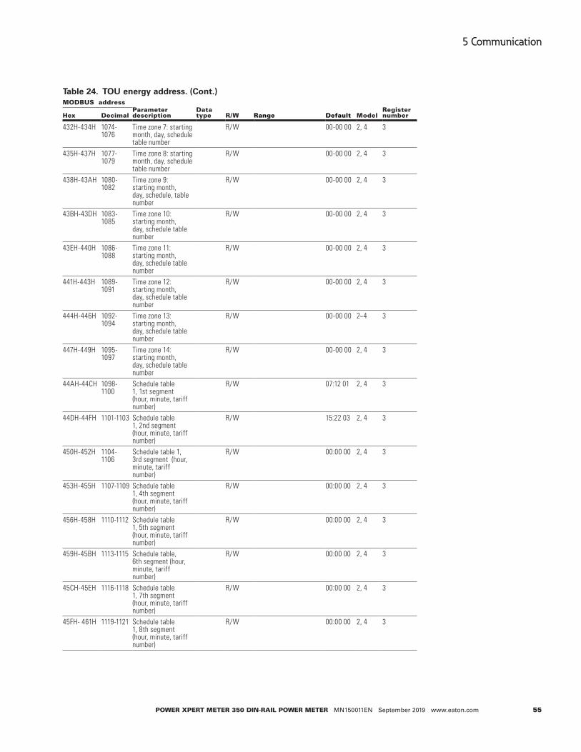
55
5 Communication
Power XPert Meter 350 DIN-raIl Power Meter MN150011EN September 2019 www.eaton.com
Table 24. TOU energy address. (Cont.)MoDBUS address
Parameterdescription
Data type r/w range Default Model
register numberHex Decimal
432H-434H 1074-1076
Time zone 7: starting month, day, schedule table number
R/W 00-00 00 2, 4 3
435H-437H 1077-1079
Time zone 8: starting month, day, schedule table number
R/W 00-00 00 2, 4 3
438H-43AH 1080-1082
Time zone 9: starting month, day, schedule, table number
R/W 00-00 00 2, 4 3
43BH-43DH 1083-1085
Time zone 10: starting month, day, schedule table number
R/W 00-00 00 2, 4 3
43EH-440H 1086-1088
Time zone 11: starting month, day, schedule table number
R/W 00-00 00 2, 4 3
441H-443H 1089-1091
Time zone 12: starting month, day, schedule table number
R/W 00-00 00 2, 4 3
444H-446H 1092-1094
Time zone 13: starting month, day, schedule table number
R/W 00-00 00 2~4 3
447H-449H 1095-1097
Time zone 14: starting month, day, schedule table number
R/W 00-00 00 2, 4 3
44AH-44CH 1098-1100
Schedule table 1, 1st segment (hour, minute, tariff number)
R/W 07:12 01 2, 4 3
44DH-44FH 1101-1103 Schedule table 1, 2nd segment (hour, minute, tariff number)
R/W 15:22 03 2, 4 3
450H-452H 1104-1106
Schedule table 1, 3rd segment (hour, minute, tariff number)
R/W 00:00 00 2, 4 3
453H-455H 1107-1109 Schedule table 1, 4th segment (hour, minute, tariff number)
R/W 00:00 00 2, 4 3
456H-458H 1110-1112 Schedule table 1, 5th segment (hour, minute, tariff number)
R/W 00:00 00 2, 4 3
459H-45BH 1113-1115 Schedule table, 6th segment (hour, minute, tariff number)
R/W 00:00 00 2, 4 3
45CH-45EH 1116-1118 Schedule table 1, 7th segment (hour, minute, tariff number)
R/W 00:00 00 2, 4 3
45FH- 461H 1119-1121 Schedule table 1, 8th segment (hour, minute, tariff number)
R/W 00:00 00 2, 4 3
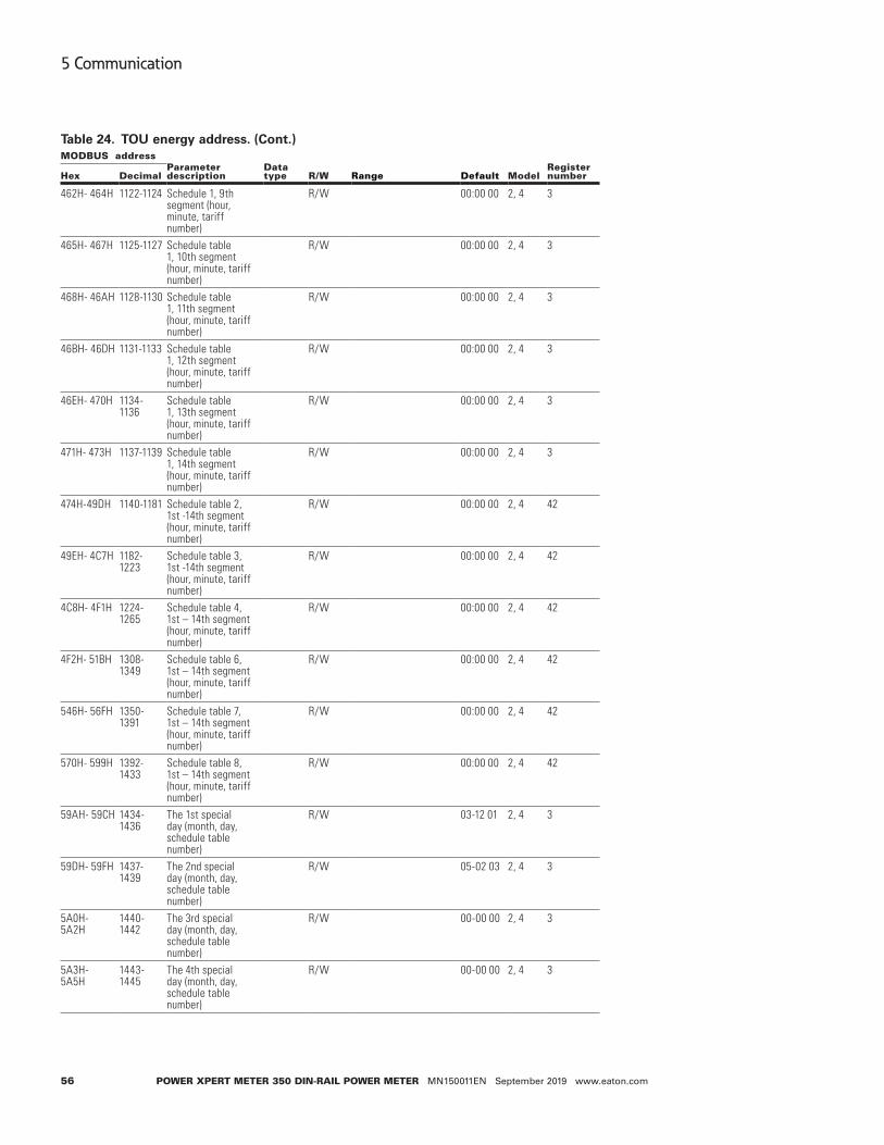
56
5 Communication
Power XPert Meter 350 DIN-raIl Power Meter MN150011EN September 2019 www.eaton.com
Table 24. TOU energy address. (Cont.)MoDBUS address
Parameterdescription
Data type r/w range Default Model
register numberHex Decimal
462H- 464H 1122-1124 Schedule 1, 9th segment (hour, minute, tariff number)
R/W 00:00 00 2, 4 3
465H- 467H 1125-1127 Schedule table 1, 10th segment (hour, minute, tariff number)
R/W 00:00 00 2, 4 3
468H- 46AH 1128-1130 Schedule table 1, 11th segment (hour, minute, tariff number)
R/W 00:00 00 2, 4 3
46BH- 46DH 1131-1133 Schedule table 1, 12th segment (hour, minute, tariff number)
R/W 00:00 00 2, 4 3
46EH- 470H 1134-1136
Schedule table 1, 13th segment (hour, minute, tariff number)
R/W 00:00 00 2, 4 3
471H- 473H 1137-1139 Schedule table 1, 14th segment (hour, minute, tariff number)
R/W 00:00 00 2, 4 3
474H-49DH 1140-1181 Schedule table 2, 1st -14th segment (hour, minute, tariff number)
R/W 00:00 00 2, 4 42
49EH- 4C7H 1182-1223
Schedule table 3, 1st -14th segment (hour, minute, tariff number)
R/W 00:00 00 2, 4 42
4C8H- 4F1H 1224-1265
Schedule table 4, 1st – 14th segment (hour, minute, tariff number)
R/W 00:00 00 2, 4 42
4F2H- 51BH 1308-1349
Schedule table 6, 1st – 14th segment (hour, minute, tariff number)
R/W 00:00 00 2, 4 42
546H- 56FH 1350-1391
Schedule table 7, 1st – 14th segment (hour, minute, tariff number)
R/W 00:00 00 2, 4 42
570H- 599H 1392-1433
Schedule table 8, 1st – 14th segment (hour, minute, tariff number)
R/W 00:00 00 2, 4 42
59AH- 59CH 1434-1436
The 1st special day (month, day, schedule table number)
R/W 03-12 01 2, 4 3
59DH- 59FH 1437-1439
The 2nd special day (month, day, schedule table number)
R/W 05-02 03 2, 4 3
5A0H- 5A2H
1440-1442
The 3rd special day (month, day, schedule table number)
R/W 00-00 00 2, 4 3
5A3H- 5A5H
1443-1445
The 4th special day (month, day, schedule table number)
R/W 00-00 00 2, 4 3
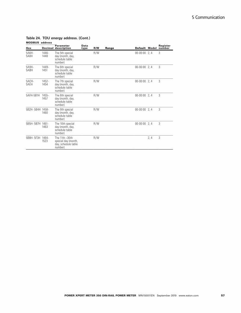
57
5 Communication
Power XPert Meter 350 DIN-raIl Power Meter MN150011EN September 2019 www.eaton.com
Table 24. TOU energy address. (Cont.)MoDBUS address
Parameterdescription
Data type r/w range Default Model
register numberHex Decimal
5A6H- 5A8H
1446-1448
The 5th special day (month, day, schedule table number)
R/W 00-00 00 2, 4 3
5A9H- 5ABH
1449-1451
The 6th special day (month, day, schedule table number)
R/W 00-00 00 2, 4 3
5ACH- 5AEH
1452-1454
The 7th special day (month, day, schedule table number)
R/W 00-00 00 2, 4 3
5AFH-5B1H 1455-1457
The 8th special day (month, day, schedule table number)
R/W 00-00 00 2, 4 3
5B2H- 5B4H 1458-1460
The 9th special day (month, day, schedule table number)
R/W 00-00 00 2, 4 3
5B5H- 5B7H 1461-1463
The 10th special day (month, day, schedule table number)
R/W 00-00 00 2, 4 3
5B8H- 5F3H 1464-1523
The 11th ~30th special day (month, day, schedule table number)
R/W 2, 4 3

58
5 Communication
Power XPert Meter 350 DIN-raIl Power Meter MN150011EN September 2019 www.eaton.com
Table 25. Last/previous month demand max. (Cont.)MoDBUS address
Parameterdescription
Data type Property range Model
register numberHex Decimal
1800H-1801H 6144-6145 Total imported active power demand peak
Float R Xx.xxxx kw 2, 4 2
1802H-1804H 6146-6147 Total imported active power demand peak time
Dword R YY/MM/DD/hh/mm/ss (second always is 0)
2, 4 3
1805H-1806H 6148-6149 Imported active power demand 1 peak
Float R Xx.xxxx kw 2, 4 2
1807H-1809H 6150-6151 Imported active power demand 1 peak time
Dword R YY/MM/DD/hh/mm/ss (second always is 0)
2, 4 3
180AH-180BH 6152-6153 Imported active power demand 2 peak
Float R Xx.xxxx kw 2, 4 2
180CH-180EH 6154-6155 Imported active power demand 2 peak time
Dword R YY/MM/DD/hh/mm/ss (second always is 0)
2, 4 3
180FH-1810H 6156-6157 Imported active power demand 3 peak
Float R Xx.xxxx kw 2, 4 2
1811H-1813H 6158-6159 Imported active power demand 3 peak time
Dword R YY/MM/DD/hh/mm/ss (second always is 0)
2, 4 3
1814H-1815H 6160-6161 Imported active power demand 4 peak
Float R Xx.xxxx kw 2, 4 2
1816H-1818H 6162-6163 Imported active power demand 4 peak time
Dword R YY/MM/DD/hh/mm/ss (Second always is 0)
2, 4 3
1819H-181AH 6164-6165 Total exported active power demand peak
Float R Xx.xxxx kw 2, 4 2
181BH-181CH 6166-6167 Total exported active power demand peak time
Dword R YY/MM/DD/hh/mm/ss (second always is 0)
2, 4 3
181DH-181EH 6168-6169 Exported active power demand 1 peak
Float R Xx.xxxx kw 2, 4 2
181FH-1821H 6170-6171 Exported active power demand 1 peak time
Dword R YY/MM/DD/hh/mm/ss (second always is 0)
2, 4 3
1822H-1823H 6172-6173 Exported active power demand 2 peak
Float R Xx.xxxx kw 2, 4 2
1824H-1826H 6174-6175 Exported active power demand 2 peak time
Dword R YY/MM/DD/hh/mm/ss (second always is 0)
2, 4 3
1827H-1828H 6176-6177 Exported active power demand 3 peak
Float R Xx.xxxx kw 2, 4 2
1829H-182BH 6178-6179 Exported active power demand 3 peak time
Dword R YY/MM/DD/hh/mm/ss (second always is 0)
2, 4 3
182CH-182DH 6180-6181 Exported active power demand 4 peak
Float R Xx.xxxx kw 2, 4 2
182EH-1830H 6182-6183 Exported active power demand 4 peak time
Dword R YY/MM/DD/hh/mm/ss (second always is 0)
2, 4 3
1831H-1832H 6184-6185 Total imported reactive power demand peak
Float R Xx.xxxx kw 2, 4 2

59
5 Communication
Power XPert Meter 350 DIN-raIl Power Meter MN150011EN September 2019 www.eaton.com
Table 25. Last/previous month demand max. (Cont.)MoDBUS address
Parameterdescription
Data type Property range Model
register numberHex Decimal
1833H-1835H 6186-6187 Total imported reactive power demand peak time
Dword R YY/MM/DD/hh/mm/ss (second always is 0)
2, 4 3
1836H-1837H 6188-6189 Imported reactive power demand 1 peak
Float R Xx.xxxx kw 2, 4 2
1838H-183AH 6190-6191 Imported reactive power demand 1 peak time
Dword R YY/MM/DD/hh/mm/ss (second always is 0)
2, 4 3
183BH-183CH 6192-6193 Imported reactive power demand 2 peak
Float R Xx.xxxx kw 2, 4 2
183DH-183FH 6194-6195 Imported reactive power demand 2 peak time
Dword R YY/MM/DD/hh/mm/ss (second always is 0)
2, 4 3
1840H-1841H 6196-6197 Imported reactive power demand 3 peak
Float R Xx.xxxx kw 2, 4 2
1842H-1844H 6198-6199 Imported reactive power demand 3 peak time
Dword R YY/MM/DD/hh/mm/ss (second always is 0)
2, 4 3
1845H-1846H 6200-6201 Imported reactive power demand 4 peak
Float R Xx.xxxx kw 2, 4 2
1847H-1849H 6202-6203 Imported reactive power demand 4 peak time
Dword R YY/MM/DD/hh/mm/ss (second always is 0)
2, 4 3
184AH-184BH 6204-6205 Total exported reactive power demand peak
Float R Xx.xxxx kw 2, 4 2
184CH-184EH 6206-6207 Total exported reactive power demand peak time
Dword R YY/MM/DD/hh/mm/ss (Second always is 0)
2, 4 3
184FH-1850H 6208-6209 Exported reactive power demand 1 peak
Float R Xx.xxxx kw 2, 4 2
1851H-1853H 6210-6211 Exported reactive power demand 1 peak time
Dword R YY/MM/DD/hh/mm/ss (second always is 0)
2, 4 3
1854H-1855H 6212-6213 Exported reactive power demand 2 peak
Float R Xx.xxxx kw 2, 4 2
1856H-1858H 6214-6215 Exported reactive power demand 2 peak time
Dword R YY/MM/DD/hh/mm/ss (second always is 0)
2, 4 3
1859H-185AH 6216-6217 Exported reactive power demand 3 peak
Float R Xx.xxxx kw 2, 4 2
185BH-185DH 6218-6219 Exported reactive power demand 3 peak time
Dword R YY/MM/DD/hh/mm/ss (second always is 0)
2, 4 3
185FH-1860H 6220-6221 Exported reactive power demand 4 peak
Float R Xx.xxxx kw 2, 4 2
1861H-1863H 6222-6223 Exported reactive power demand 4 peak h time
Dword R YY/MM/DD/hh/mm/ss (second always is 0)
2, 4 3
1864H-1865H 6224-6225 Total apparent power demand peak
Float R Xx.xxxx kw 2, 4 2
1866H-1868H 6226-6227 Total apparent power demand peak time
Dword R YY/MM/DD/hh/mm/ss (second always is 0)
2, 4 3

60
5 Communication
Power XPert Meter 350 DIN-raIl Power Meter MN150011EN September 2019 www.eaton.com
Table 25. Last/previous month demand max. (Cont.)MoDBUS address
Parameterdescription
Data type Property range Model
register numberHex Decimal
1869H-186AH 6228-6229 Phase a current demand peak
Float R Xx.xxxx A 2, 4 2
186BH-186DH 6230-6231 Phase A current demand peak time
Dword R YY/MM/DD/hh/mm/ss second always is 0)
2, 4 3
186EH-186FH 6232-6233 Phase B current demand peak
Float R Xx.xxxx A 2, 4 2
1870H-1872H 6234-6235 Phase B current demand peak time
Dword R YY/MM/DD/hh/mm/ss (second always is 0)
2, 4 3
1873H-1874H 6236-6237 Phase C current demand peak
Float R Xx.xxxx A 2, 4 2
1875H-1877H 6238-6239 Phase C current demand peak time
Dword R YY/MM/DD/hh/mm/ss (second always is 0)
2, 4 3
Table 26. TOU week alternatives. (Cont.)MoDBUS address
Parameterdescription
Data type
access property range Default Model
register numberHex Decimal
7F00H 32512 Enable weekend alternative
Word R/W 1: Enable; 0: Disable
0 2, 4 1
7F01H 32513 Season 1: Sign of the weekend
Word R/W Bit0: Sunday, 1 enable, 0 disable; Bit1: Monday, 1 enable, 0 disable; …… Bit6: Saturday, 1 enable, 0 disable;
0 2, 4 1
7F02H 32514 Season 1: The schedule table number of Sunday
Word R/W 0 2, 4 1
7F03H 32515 Season 1: The schedule table number of Monday
Word R/W 0 2, 4 1
7F04H 32516 Season 1: The schedule table number of Tuesday
Word R/W 0 2, 4 1
7F05H 32517 Season 1: The schedule table number of Wednesday
Word R/W 2, 4 1
7F06H 32518 Season 1: The schedule table number of Thursday
Word R/W 2, 4
7F07H 32519 Season 1: The schedule table number of Friday
Word R/W 2, 4
7F08H 32520 Season 1:The schedule table number of Saturday
Word R/W 2, 4
7F09H - 7F10H
32521-32522
Season 2 of weekend alternative
Word R/W 2, 4
7F11H –7F18H
32523 -32536
Season 3 of weekend alternative
Word R/W 2, 4
7F19H –7F20H
32537-32538
Season 4 of weekend alternative
Word R/W 2, 4

61
5 Communication
Power XPert Meter 350 DIN-raIl Power Meter MN150011EN September 2019 www.eaton.com
Table 26. TOU week alternatives. (Cont.)MoDBUS address
Parameterdescription
Data type
access property range Default Model
register numberHex Decimal
7F21H –7F28H
32539 -32552
Season 5 of weekend alternative
Word R/W 2, 4
7F29H –7F30H
32553 -32554
Season 6 of weekend alternative
Word R/W 2, 4
7F31H –7F38H
32555 - 32568
Season 7 of weekend alternative
Word R/W 2, 4
7F39H –7F40H
32569 -32570
Season 8 of weekend alternative
Word R/W 2, 4
7F41H –7F48H
32571 - 32584
Season 9 of weekend alternative
Word R/W 2, 4
7F49H –7F50H
32585 - 32586
Season 10 of weekend alternative
Word R/W 2, 4
7F51H –7F58H
32587 - 32600
Season 11 of weekend alternative
Word R/W 2, 4
7F59H –7F60H
32601-32602
Season 12 of weekend alternative
Word R/W 2, 4
7F61H –7F68H
32603 - 32616
Season 13 of weekend alternative
Word R/W 2, 4
7F69H –7F70H
32617 - 32618
Season 14 of weekend alternative
Word R/W 2, 4
Rate parameter error information word 1 (basic parameter)
Table 27. Rate parameter error information word 1.Bit7 Bit6 Bit5 Bit4 Bit3 Bit2 Bit1 Bit0
1 1 1 1 1 1 1 1
Time segment table 8 error
Time segment table 7 error
Time segment table 6 error
Time segment table 5 error
Time segment table 4 error
Time segment table 3 error
Time segment table 2 error
Time segment table 1 error
Rate parameter error information word 2 (time segment table parameter)
Table 28. Rate parameter error information word 2.
Bit7 Bit6 Bit5 Bit4 Bit3 Bit2 Bit1 Bit0
1 1 1 1 1 1 1 1
Time segment table 8 error
Time segment table 7 error
Time segment table 6 error
Time segment table 5 error
Time segment table 4 error
Time segment table 3 error
Time segment table 2 error
Time segment table 1 error

62
5 Communication
Power XPert Meter 350 DIN-raIl Power Meter MN150011EN September 2019 www.eaton.com
Alarm parameter setting (function code: 03H to read; 10H to write).
Table 29. Alarm parametersMoDBUS address
Parameterdescription
Data type r/w range Default Model
register numberHex Decimal
700H 1792 Alarm switch Word R/W 1: Enable; 0: Disable
0 2, 4 1
701H 1793 Alarm channel Word R/W Bit0~Bit11: Alarm channel 0-11 1: Enable; 0: Disable
0 2, 4 1
702 1794 Alarm channel output
Word R/W Bit0~ Bit11: Alarm channel 0-11 1: Enable; 0: Disable
0 2, 4 1
703 1795 Alarm output mode
Word R/W 0: Level; 1: Pulse
0 2, 4 1
704H 1796 Pulse output time Word R/W 50~3000 ms (valid with pulse output mode)
1000 2, 4 1
alarm parameter setting for the 1st group
705H 1797 Parameter number
Word R/W 0~28 (Please see appendix “Alarm parameter comparison table")
0 2, 4 1
706H 1798 Comparing method
Word R/W 0: Larger; 1: Equal; 2: Less
0 2, 4 1
707H 1799 Setpoint value Word R/W 0: Larger; 1: Equal; 2: Less
0 2, 4 1
708H 1800 Delay time Word R/W 0~3000 (x10ms) 0 2, 4 1
alarm parameter setting for the 2nd 12th group
709H- 703BH
1801-1851 The same as above
Word R/W 2, 4 44
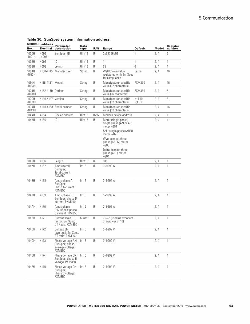
63
5 Communication
Power XPert Meter 350 DIN-raIl Power Meter MN150011EN September 2019 www.eaton.com
Table 30. SunSpec system information address. (Cont.)MoDBUS address
Parameterdescription
Data type r/w range Default Model
register numberHex Decimal
1000H -1001H
4096 -4097
SunSpec_ID Uint16 R 0x53756e53 1 2, 4 2
1002H 4098 ID Uint16 R 1 1 2, 4 11003H 4099 Length Uint16 R 65 6 2, 4 11004H -1013H
4100-4115 Manufacturer String R Well known value registered with SunSpec for compliance
Eaton 2, 4 16
1014H -1023H
4116-4131 Model String R Manufacturer specific value (32 characters)
PXM350 2, 4 16
1024H -102BH
4132-4139 Options String R Manufacturer specific value (16 characters)
PXM350 2, 4 8
102CH -1033H
4140-4147 Version String R Manufacturer specific value (32 characters)
H: 1.10 S;1.01
2, 4 8
1034H -1043H
4148-4163 Serial number String R Manufacturer specific value (32 characters)
2, 4 16
1044H 4164 Device address Uint16 R/W Modbus device address 2, 4 11045H 4165 ID Uint16 R Meter (single phase)
single phase (AN or AB) meter –201 Split single phase (ABN) meter -202 Wye-connect three phase (ABCN) meter –203 Delta-connect three phase (ABC) meter –204
2, 4 1
1046H 4166 Length Uint16 R 105 2, 4 11047H 4167 Amps (total):
SunSpec; Total current PXM350
Int16 R 0~9999 A 2, 4 1
1048H 4168 Amps phase A: SunSpec; Phase A current PXM350
Int16 R 0~9999 A 2, 4 1
1049H 4169 Amps phase B: SunSpec; phase B current: PXM350
Int16 R 0~9999 A 2, 4 1
104AH 4170 Amps phase C:SunSpec; phase C current PXM350
Int16 R 0~9999 A 2, 4 1
104BH 4171 Current scale factor: SunSpec; CT Ratio: PXM350
Sunssf R -3~+5 (used as exponent of a power of 10)
2, 4 1
104CH 4172 Voltage LN (average): SunSpec; CT ratio: PXM350
Int16 R 0~9999 V 2, 4 1
104DH 4173 Phase voltage AN: SunSpec; phase average voltage: PXM350
Int16 R 0~9999 V 2, 4 1
104EH 4174 Phase voltage BN: SunSpec; phase B voltage: PXM350
Int16 R 0~9999 V 2, 4 1
104FH 4175 Phase voltage CN: SunSpec; Phase C voltage: PXM350
Int16 R 0~9999 V 2, 4 1

64
5 Communication
Power XPert Meter 350 DIN-raIl Power Meter MN150011EN September 2019 www.eaton.com
Table 30. SunSpec system information address. (Cont.)MoDBUS address
Parameterdescription
Data type r/w range Default Model
register numberHex Decimal
1050H 4176 Voltage LL (average): SunSpec; line aaverage voltage: PXM350
Int16 R 0~9999 V 2, 4 1
1051H 4177 Phase voltage AB: SunSpec; Line AB voltage: PXM350
Int16 R 0~9999 V 2, 4 1
1052H 4178 Phase voltage BC: SunSpec; line BC voltage PXM350
Int16 R 0~9999 V 2, 4 1
1053H 4179 Phase voltage CA: SunSpec;line CA voltage: PXM350
Int16 R 0~9999 V 2, 4 1
1054H 4180 Voltage scale factor: SunSpec
Sunssf R -2~2 2, 4 1
1055H 4181 Frequency Int16 R 45Hz-65Hz 2, 4 11056H 4182 Frequency scale
factorSunssf R -2 2, 4 1
1057H 4183 Total real power SunSpec; total active power: PXM350
Int16 R 0~9999 W 2, 4 1
1058H 4184 Watts phase A: SunSpec; total active power: PXM350
Int16 R 0~9999 W 2, 4 1
1059H 4185 Watts phase A: SunSpec; phase A active power: PXM350
Int16 R 0~9999 W 2, 4 1
105AH 4186 Watts phase C: SunSpec; phase C active power: PXM350
Int16 R 0~9999 W 2, 4 1
105BH 4187 Real power scale factor: SunSpec;
Sunssf R 0~4 2, 4 1
105CH 4188 AC apparent power VA: SunSpec; total apparent power: PXM350
Int16 R 0~9999 VA 2, 4 1
105DH 4189 VA phase A: SunSpec; phase A apparent power: PXM350
Int16 R 0~9999 VA 2, 4 1
105EH 4190 VA phase B: SunSpec; phase B apparent power: PXM350
Int16 R 0~9999 VA 2, 4 1
105FH 4191 VA phase C: SunSpec; phase C apparent power: PXM350
Int16 R 0~9999 VA 2, 4 1
1060H 4192 Apparent power scale factor: SunSpec;
Sunssf R 0~4 2, 4 1
1061H 4193 Reactive power VAR: SunSpec; total reactive power: PXM350
Int16 R 0~9999 VAR 2, 4 1
1062H 4194 VAR phase A: SunSpec; phase A reactive power: PXM350
Int16 R 0~9999 VAR 2, 4 1
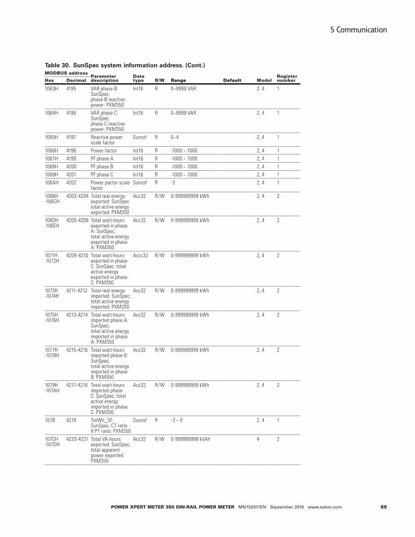
65
5 Communication
Power XPert Meter 350 DIN-raIl Power Meter MN150011EN September 2019 www.eaton.com
Table 30. SunSpec system information address. (Cont.)MoDBUS address
Parameterdescription
Data type r/w range Default Model
register numberHex Decimal
1063H 4195 VAR phase B: SunSpec; phase B reactive power: PXM350
Int16 R 0~9999 VAR 2, 4 1
1064H 4196 VAR phase C: SunSpec; phase C reactive power: PXM350
Int16 R 0~9999 VAR 2, 4 1
1065H 4197 Reactive power scale factor
Sunssf R 0~4 2, 4 1
1066H 4198 Power factor Int16 R -1000 ~ 1000 2, 4 11067H 4199 PF phase A Int16 R -1000 ~ 1000 2, 4 11068H 4200 PF phase B Int16 R -1000 ~ 1000 2, 4 11069H 4201 PF phase C Int16 R -1000 ~ 1000 2, 4 1106AH 4202 Power pactor scale
factorSunssf R -3 2, 4 1
106BH -106CH
4203-4204 Total real energy exported: SunSpec total active energy exported: PXM350
Acc32 R/W 0-999999999 kWh 2, 4 2
106DH -106EH
4205-4206 Total watt-hours exported in phase A: SunSpec; total active energy exported in phase A: PXM350
Acc32 R/W 0-999999999 kWh 2, 4 2
1071H -1072H
4209-4210 Total watt-hours exported in phase C: SunSpec; total active energy exported in phase C: PXM350
Accc32 R/W 0-999999999 kWh 2, 4 2
1073H -1074H
4211-4212 Total real energy imported: SunSpec; total active energy imported: PXM350
Acc32 R/W 0-999999999 kWh 2, 4 2
1075H -1076H
4213-4214 Total watt-hours imported phase A: SunSpec; total active energy imported in phase A: PXM350
Acc32 R/W 0-999999999 kWh 2, 4 2
1077H -1078H
4215-4216 Total watt-hours imported phase B: SunSpec; total active energy imported in phase B: PXM350
Acc32 R/W 0-999999999 kWh 2, 4 2
1079H -107AH
4217-4218 Total watt-hours imported phase C: SunSpec; total active energy imported in phase C: PXM350
Acc32 R/W 0-999999999 kWh 2, 4 2
107B 4219 TotWh_SF: SunSpec; CT ratio X PT ratio: PXM350
Sunssf R -3 ~ 0 2, 4 1
107CH -107DH
4220-4221 Total VA-hours exported: SunSpec; total apparent power exported: PXM350
Acc32 R/W 0-999999999 kVAh 4 2

66
5 Communication
Power XPert Meter 350 DIN-raIl Power Meter MN150011EN September 2019 www.eaton.com
Table 30. SunSpec system information address. (Cont.)MoDBUS address
Parameterdescription
Data type r/w range Default Model
register numberHex Decimal
107EH -17FH
4222-4223 Total VA-hours exported phase A: SunSpec; total apparent power exported in phase A: PXM350
Acc32 R/W 0-999999999 kVAh 4 2
1080H -1081H
4224-4225 Total VA-hours exported phase B: SunSpec; total apparent power exported in phase A:PXM350
Acc32 R/W 0-999999999 kVAh 4 2
1082H -1083H
4226-4227 Total VA-hours exported phase C: SunSpec; total apparent power exported in phase C: PXM350
Acc32 R/W 0-999999999 kVAh 4 2
1084H -1085H
4228-4229 Total VA-hours imported: SunSpec; total apparent power imported: PXM350
Acc32 R/W 0-999999999 kVAh 2, 4 2
1086H -1087H
4230-4231 Total VA-hours imported phase A: SunSpec; total apparent power imported in phase A: PXM350
Acc32 R/W 0-999999999 kVAh 2, 4 2
1088H -1089H
4232-4233 Total VA-hours imported phase B: SunSpec; total apparent power imported in phase B: PXM350
Acc32 R/W 0-999999999 kVAh 2, 4 2
108AH -108BH
4234-4235 Total VA-hours imported phase C: SunSpec; total apparent power imported in phase C: PXM350
Acc32 R/W 0-999999999 kVAh 2, 4 2
108CH 4236 Total VAh_SF: SunSpec; CT ratio X PT ratio: PXM350
Sunssf R -3 ~ 0 2, 4 1
108DH -108EH
4237-4238 Total VAR-hours imported Q1:SunSpec;
Acc32 R/W 0-999999999 kvarh 2, 4 2
108FH -1090H
4239-4240 Total VAR-hours imported Q1 phase 1A
Acc32 R/W 0-999999999 kvarh 2, 4 2
1091H -1092H
4241-4242 Total VAR-hours imported Q1 phase B
Acc32 R/W 0-999999999 kvarh 2, 4 2
1093H -1094H
4243-4244 Total VAR-hors imported Q1 phase C
Acc32 R/W 0-999999999 kvarh 2, 4 2
1095H -1096H
4245-4246 Total VAR-hours imported Q2 phase A
Acc32 R/W 0-99k9999999 kvarh 2, 4 2
1097H -1098H
4247-4248 Total VAR-hours imported Q2 phase A
Acc32 R/W 0-999999999 kvarh 2, 4 2
1099H -109AH
4249-4250 Total VAR-hours imported Q2 phase B
Acc32 R/W 0-999999999 kvarh 2, 4 2

67
5 Communication
Power XPert Meter 350 DIN-raIl Power Meter MN150011EN September 2019 www.eaton.com
Table 30. SunSpec system information address. (Cont.)MoDBUS address
Parameterdescription
Data type r/w range Default Model
register numberHex Decimal
109BH -109CH
4251-4252 Total VAR-hours imported Q2 phase C
Acc32 R/W 0-999999999 kvarh 2, 4 2
109DH -109EH
4253-4254 Total VAR-hours exported Q3
Acc32 R/W 0-999999999 kvarh 2, 4 2
109FH -10AH
4255-4256 Total VAR-hours exported Q3 phase A
Acc32 R/W 0-999999999 kvarh 2, 4 2
10A1H -10A2H
4257-4258 Total VAR-hours exported Q3 phase B
Acc32 R/W 0-999999999 kvarh 2, 4 2
10A3H -10A4H
4259-4260 Total VAR-hours exported Q3 phase C
Acc32 R/W 0-999999999 kvarh 2, 4 2
10A5H -10A6H
4261-4262 Total VAR-hours exported Q4
Acc32 R/W 0-999999999 kvarh 2, 4 2
10A7H -10A8H
4263-4264 Total VAR-hours exported Q4 phase A
Acc32 R/W 0-999999999 kvarh 2, 4 2
10A9H -10AAH
4265-4266 Total VAR-hours exported Q4 phase B
Acc32 R/W 0-999999999 kvarh 2, 4 2
10ABH -10ACH
4267-4268 Total VAR-hours exported Q4 phase C
Acc32 R/W 0-999999999 kvarh 2~4 2
10ADH 4269 Total VARh_SF: SunSpec; CT ratio X PT ratio: PXM350
Sussf R All the energy use the same SF
2, 4 1
10AEH -10AFH
4270-4271 Meter eventflags Bitfield32 R 0 0 2, 4 2
10B0H 4272 SunSpec_end_ID: SunSPec;
Uint16 0xFFFF 2, 4 1
10B1H 4273 SunSpec_end_length: SunSpec
Uint16 0x0000 2, 4 1

68
5 Communication
Power XPert Meter 350 DIN-raIl Power Meter MN150011EN September 2019 www.eaton.com
Table 31. Current maximum demand and time of occurrence address. (Cont.)MoDBUS address
Parameterdescription
Data type r/w range Default Model
register numberHex Decimal
Current maximum demand and time of occurrence data
1600H-1601H 1602H-1604H
5632-5633 5634-5636
Input active power total max demand and occur time
Float Dword
R xx.xxxx kW YYMMDDhhmmss (Second always be 0)
4 2 3
1605H-1606H 1607H-1609H
5637-5638 5639-5641
Input active power max demand 1 and occur time
Float Dword
R xx.xxxx kW YYMMDDhhmmss
4 2 3
160AH-160BH 160CH-160EH
5642-5643 5644-5646
Input active power max demand 2 and occur time
Float Dword
R xx.xxxx kW YYMMDDhhmmss
4 2 3
160FH-1600H 1611H-1613H
5647-5648 5649-5651
Input active power max demand 3 and occur time
Float Dword
R xx.xxxx kW YYMMDDhhmmss
4 2 3
1614H-1615H 1616H-1618H
5652-5653 5654-5656
Input active power max demand 4 and occur time
FloatDword
R xx.xxxx kW YYMMDDhhmmss
4 2 3
1619H-161AH 161BH-161DH
5657-5658 5659-5661
Output active powers total max demand and occur time
Float Dword
R xx.xxxx kW YYMMDDhhmmss
4 2 3
161EH-161FH 1620H-1622H
5662-5663 5664-5666
Output active power max demand 1 and occur time
Float DWORD
R xx.xxxx kW YYMMDDhhmmss
4 2 3
1623H-1624H 1625H-1627H
5667-5668 5669-5671
Output active power max demand 2 and occur time
Float Dword
R xx.xxxx kW YYMMDDhhmmss
4 2 3
1628H-1629H 162AH-162C
5672-5673 5674-5676
Output active power max demand 3 and occur time
Float Dword
R xx.xxxx kW YYMMDDhhmmss
4 2 3
162DH-162EH 162FH-1631H
5677-5678 5679-5681
Output active power max demand 4 and occur time
Float Dword
R xx.xxxx kW YYMMDDhhmmss
4 2 3
1632H-1633H 1634H-1636H
5682-5683 5684-5686
Input reactive power max demand 1 and occur time
Float Dword
R xx.xxxx kvar YYMMDDhhmmss
4 2 3
1637H-1638H 1639H-163BH
5687-5688 5689-5691
Input reactive power max demand 1 and occur time
Float Dword
R xx.xxxx kvar YYMMDDhhmmss
4 2 3
163CH-163DH 163EH-1640H
5692-5693 5694-5696
Input reactive power max demand 2 and occur time
Float Dword
R xx.xxxx kvar YYMMDDhhmmss
4 2 3
1641H-1642H 1643H-1645H
5697-5698 5699-5701
Input reactive power max demand 3 and occur time
Float Dword
R xx.xxxx kvar YYMMDDhhmmss
4 2 3
1646H-1647H 1648H-164AH
5702-5703 5704-5706
Input reactive power max demand 4 and occur time
Float Dword
R xx.xxxx kvar YYMMDDhhmmss
4 2 3
164BH-164CH 164DH-164FH
5707-5708 5709-5711
Output reactive powers total max demand and occur
Float Dword
R xx.xxxx kvar YYMMDDhhmmss
4 2 3
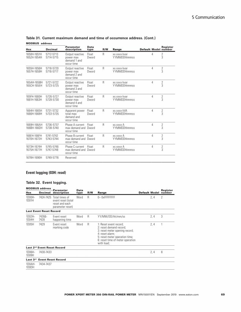
69
5 Communication
Power XPert Meter 350 DIN-raIl Power Meter MN150011EN September 2019 www.eaton.com
Table 31. Current maximum demand and time of occurrence address. (Cont.)MoDBUS address
Parameterdescription
Data type r/w range Default Model
register numberHex Decimal
1650H-1651H 1652H-1654H
5712-5713 5714-5715
Output reactive power max demand 1 and occur time
Float Dword
R xx.xxxx kvar YYMMDDhhmmss
4 2 3
1655H-1656H 1657H-1659H
5718-5720 5716-5717
Output reactive power max demand 2 and occur time
Float Dword
R xx.xxxx kvar YYMMDDhhmmss
4 2 3
165AH-165BH 165CH-165EH
5721-5722 5723-5725
Output reactive power max demand 3 and occur time
Float Dword
R xx.xxxx kvar YYMMDDhhmmss
4 2 3
165FH-1660H 1661H-1663H
5726-5727 5728-5730
Output reactive power max demand 4 and occur time
Float Dword
R xx.xxxx kvar YYMMDDhhmmss
4 2 3
1664H-1665H 1666H-1668H
5731-5732 5733-5735
Apparent power total max demand and occur time
Float Dword
R xx.xxxx kVA YYMMDDhhmmss
4 2 3
1669H-166AH 166BH-166DH
5736-5737 5738-5740
Phase A current max demand and occur time
Float Dword
R xx.xxxx A YYMMDDhhmmss
4 2 3
166EH-166FH 1670H-1672H
5741-5742 5743-5744
Phase B current max demand and occur time
Float Dword
R xx.xxxx A YYMMDDhhmmss
4 2 3
1673H-1674H 1675H-1677H
5745-5746 5747-5748
Phase C current max demand and occur time
Float Dword
R xx.xxxx A YYMMDDhhmmss
4 2 3
1678H-1690H 5749-5776 Reserved
Event logging (03H: read)
Table 32. Event logging.
MoDBUS addressParameterdescription
Data type r/w range Default Model
register numberHex Decimal
1D00H-1D01H
7424-7425 Total times of event reset (total reset and each parameter reset)
Word R 0~ 0xFFFFFFFF 2, 4 2
last event reset record
1D02H-1D04H
74266-7428
Event reset happening time
Word R YY/MM/DD/hh/mm/ss 2, 4 3
1D05H 7429 Event reset marking code
Word R 1: Reset event record; 2: reset demand record; 3: reset meter opening record; 4: reset alarm; 5: reset meter operation time; 6: reset time of meter operation with load;
2, 4 1
last 2nd event reset record
1D06H-1D09H
7430-7433 2, 4 8
last 3rd event reset record
1D0AH-1D0DH
7434-7437

70
5 Communication
Power XPert Meter 350 DIN-raIl Power Meter MN150011EN September 2019 www.eaton.com
Programming record
Table 33. Programming record address.Modbus address
Parameterdescription
Data type r/w range Default Model
register numberHex Decimal
1A00H-1A01H 6656-6657 Total programming time Dword R 0-999999 2, 4 2last event reset record
1A02H-1A04H 6658-6660 Occur time Word R YYMMDD hhmmss
2, 4 3
last 2nd event reset record
1A06H-1A0DH 6662-6669 2, 4 8Note*:System event marking:01: Meter address change 02: RS-485 parameter change(including baud rate and parity bit setting)03: Energy pulse setting 04: Demandparameter setting(calculation method, demand period, slipping time) 05: Reactive power calculation method 06: VAR/PF convention 07: Date and time setting 08: Measure side change 09: Wring mode 10: CT or PT change 11: Pulse constant and pulse width12: Decimal digits 13: RO output mode 14: Arm setting parameter 100: Energy value base 101: TOU parameter setting102: Daylight saving time 103: Trend record104: Alarm set parameters change
Demand clearance event
Table 34. Demand clearance address.
Modbus addressParameterdescription
Data type r/w range Default Model
register numberHex Decimal
1B00H-1B01H 6912-6913 Total times of demand reset
Word R 0~0xFFFFFFFF 2, 4 2
last time open cover record
1B02H-1B04H 6914-6916 Occur time Word R YYMMDDhhmmss 2, 4 3last 2nd – 3rd time
1B05H-1B0AH 6917-6916 2, 4 6
Open cover record
Table 35. Open cover record address.Modbus address
Parameterdescription
Data type r/w range Default Model
register numberHex Decimal
1C00H-1C01H 7168-7169 Total open cover time Word R 0-999999 2, 4 2last time open cover record
1C02H-1C04H 7170-7172 Occur time Word R YYMMDDhhmmss 2, 4 31C05H-1C07H 7173-7175 End time Word R 2, 4 3last 2nd – 3rd time
1C08H-1C13H 7176-7187 2, 4 12

71
5 Communication
Power XPert Meter 350 DIN-raIl Power Meter MN150011EN September 2019 www.eaton.com
Event Clearance
Table 36. Event clearance address.Modbus address
Parameterdescription
Data type r/w range Default Model
register numberHex Decimal
1B00H-1B01H 6912-6913 Total times of demand reset
Word R 0~0xFFFFFFFF 2, 4 2
last time open cover record
1B02H-1B04H 6914-6916 Occur time Word R YYMMDDhhmmss 2, 4 3last 2nd – 3rd time
1B05H-1B0AH 6917-6916 2, 4 6
Open cover record
Table 37. Open cover record address.Modbus address
Parameterdescription
Data type r/w range Default Model
register numberHex Decimal
1C00H-1C01H 7168-7169 Total open cover time Word R 0-999999 2, 4 2last time open cover record
1C02H-1C04H 7170-7172 Occur time Word R YYMMDDhhmmss 2, 4 31C05H-1C07H 7173-7175 End time Word R 2, 4 3last 2nd – 3rd time
1C08H-1C13H 7176-7187 2, 4 12
Event clearance
Table 38. Event clearance address.Modbus address
Parameterdescription
Data type r/w range Default Model
register numberHex Decimal
1D00H-1D01H 7424-7425 Total event clearance time
Word R 2, 4 2
last time open cover record
1D02H-1D04H 7426-7428 Occur time Word R YYMMDDhhmmss 2, 4 3
1D05H 7429 Event clearance data flag
Word R 1: clear the programming records 2: clear demand records 3: clear open cover records
2, 4 1
last 2nd – 3rd time
1D06H-1D0DH 7430-7437 2, 4 8

72
5 Communication
Power XPert Meter 350 DIN-raIl Power Meter MN150011EN September 2019 www.eaton.com
Meter clearance event
Table 39. Meter clearance address.Modbus address
Parameterdescription
Data type r/w range Default Model
register numberHex Decimal
1E00H-1E01H 7680-7681 Total meter clearance time
Word R 0-999999 2, 4 2
last time meter cleared record
1E02H-1E04H 7682-7684 Occur time Word R YYMMDDhhmmss 2, 4 3last 2nd – 3rd time
1E05H-1E0AH 7685-7690 2, 4 6
RO control function (01H read, 05H write)
RO state read (01H)
Table 40. RO control function-01H read.
Modbus address (HeX)
Parameter description Data type r/w Data range Default Model
register number
0000H RO state Word R 1: ON 0: OFF 1
RO control (05H)
Table 41. RO control function-05H write.
Modbus address (HeX)
Parameter description Data type r/w Data range Default Model
register number
0000H RO control Word W FF00: ON 0000: OFF
1
5.4 BACnet MSTPBACnet overview
The Building Automation and Control Network (BACnet), described in the ANSI/ASHRAE Standard 135-2016, is one of the most widely used building management systems protocols. BACnet is designed to allow communication of building automation and control systems for applications such as heating, ventilation, and air conditioning, lighting control, access control, and fire detection systems and their associated equipment. The BACnet protocol provides mechanisms for computerized building automation devices to exchange information, regard-less of the particular building service they perform.
Introduction
The PXM350 meter supports BACnet communication using BACnet MSTP communication and communicates with most building automation/control systems, and communicates with the BACnet MSTP via RS-485. The PXM350 meter's BACnet MSTP protocol supports has 90 predefined BACnet objects that lets you track up to 90 measurements.
About BACnet protocol
The BACnet protocol operates in a client-server environment. A client machine sends a service request (message) to a server machine; once the service is performed the results are reported back to the client machine. BACnet defines 5 groups (or classes) of 35 message types. For example, one class contains messages for retrieving and manipulating the object properties described above. An example of a common service request in this class is "ReadProperty". When the server machine receives this message from a client machine, it locates the requested property of the requested object and sends the value to

73
5 Communication
Power XPert Meter 350 DIN-raIl Power Meter MN150011EN September 2019 www.eaton.com
the client. The BACnet protocol consists of objects that contain different kinds of informa-tion. Each object has properties that contain data related to it.
Below is the example from the AXM-BMS (BACnet MSTP protocol) of an object for total watts:
• Object_Name, P_rms
• Object_Type, AnalogValue
• Object_Instance, 17
• Present_Value, watt, tot (value in watts)
For more detailed information, visit the BACnet website at www.bacnet.org.
Using the PXM350 meter’s BACnet protocol
There are different serial and Ethernet based versions of BACnet. The most common serial version is called BACnet MSTP while the dominant Ethernet version is BACnet IP.
The PXM350 only supports the BACnet MSTP version.
Table 42. BACnet MSTP characteristics.BaCnet MS characteristics
Data Up to 480 bytes per telegram frame.Installation Any cable with at least three conductors can be used. Distance between nodes
depends on baud rate.Max. station 127 MSTP masters.Network type Serial RS-485 with a Master/Slave Token Passing protocol.Speed 9600 kbit/s, 19200 kbit/s, 38400 kbit/s, and 76800 kbit/s.Topology Serial RS-485 with a Master/Slave Token Passing protocol.
BACnet objects
The PXM350 meters support 90 predefined objects based on the meters real-time measure-ment parameters. There is no programming or mapping necessary to use the BACnet objects. The object's name easily identifies the measurement they contain.
The following objects have the object type as Analog Inputs. The following table lists each of the objects with their instance number and the units of measurement.

74
5 Communication
Power XPert Meter 350 DIN-raIl Power Meter MN150011EN September 2019 www.eaton.com
Table 43. BACnet objects. (Cont.)Instance object type Name Units
1 Object analog input Frequency Hertz2 Object analog input Phase A voltage Volts3 Object analog input Phase B voltage Volts4 Object analog input Phase C voltage Volts5 Object analog input Average phase voltage Volts6 Object analog input Line voltage AB Volts7 Object analog input Line voltage BC Volts8 Object analog input Line voltage CA Volts9 Object analog input Average line voltage Volts10 Object analog input Phase A current Amperes11 Object analog input Phase B current Amperes12 Object analog input Phase C current Amperes13 Object analog input Total current Amperes14 Object analog input Neutral current Amperes15 Object analog input Phase A active power kW16 Object analog input Phase B active power kW17 Object analog input Phase C active power kW18 Object analog input Total active power kW19 Object analog input Phase A reactive power kVAR20 Object analog input Phase B reactive power kVAR21 Object analog input Phase C reactive power kVAR22 Object analog input Total reactive power kVAR23 Object analog input Phase A apparent power kVA24 Object analog input Phase B apparent power kVA25 Object analog input Phase C apparent power kVA26 Object analog input Total apparent power kVA27 Object analog input Phase A power factor -28 Object analog input Phase B power factor -29 Object analog input Phase C power factor -30 Object analog input Total power factor -31 Object analog input Load type -32 Object analog input Active power demand kW33 Object analog input Reactive power demand kVAR34 Object analog input Apparent power demand kVA35 Object analog input Phase A current demand Amperes36 Object analog input Phase B current demand Amperes37 Object analog input Phase C current demand Amperes38 Object analog input System active power demand prediction kW39 Object analog input System reactive power demand prediction kVAR40 Object analog input System apparent power demand prediction kVA41 Object analog input Phase A current demand prediction Amperes42 Object analog input Phase B current demand prediction Amperes43 Object analog input Phase C current demand prediction Amperes44 Object analog input Temperature of chips Degrees Celsius45 Object analog input Import active energy kWh46 Object analog input Export active energy kWh47 Object analog input Import reactive energy kVARh48 Object analog input Export reactive energy kVARh49 Object analog input Import apparent power kVAh50 Object analog input Export apparent power kVAh

75
5 Communication
Power XPert Meter 350 DIN-raIl Power Meter MN150011EN September 2019 www.eaton.com
Table 43. BACnet objects. (Cont.)Instance object type Name Units
51 Object analog input Active energy total kWh52 Object analog input Active energy net kWh53 Object analog input Reactive energy total kVARh54 Object analog input Reactive energy net kVARh55 Object analog input Phase A import active energy kWh56 Object analog input Phase A export active energy kWh57 Object analog input Phase B import active energy kWh58 Object analog input Phase B export active energy kWh59 Object analog input Phase C import active energy kWh60 Object analog input Phase C export active energy kWh61 Object analog input Reactive imported Q1 kVARh62 Object analog input Reactive imported Q2 kVARh63 Object analog input Reactive imported Q3 kVARh64 Object analog input Reactive imported Q4 kVARh65 Object analog input Phase A reactive imported Q1 kVARh66 Object analog input Phase A reactive imported Q2 kVARh67 Object analog input Phase A reactive imported Q3 kVARh68 Object analog input Phase A reactive imported Q4 kVARh69 Object analog input Phase B reactive imported Q1 kVARh70 Object analog input Phase B reactive imported Q2 kVARh71 Object analog input Phase B reactive imported Q3 kVARh72 Object analog input Phase B reactive imported Q4 kVARh73 Object analog input Phase C reactive imported Q1 kVARh74 Object analog input Phase C reactive imported Q2 kVARh75 Object analog input Phase C reactive imported Q3 kVARh76 Object analog input Phase C reactive imported Q4 kVARh77 Object analog input Phase A import apparent energy kVAh78 Object analog input Phase A export apparent energy kVAh79 Object analog input Phase B import apparent energy kVAh80 Object analog input Phase B export apparent energy kVAh81 Object analog input Phase C import apparent energy kVAh82 Object analog input Phase C export apparent energy kVAh83 Object analog input Current imported active power demand peak and
happening timekW
84 Object analog input Current exported active power demand peak and happening time
kW
85 Object analog input Last month imported active power demand peak and happening time
kW
86 Object analog input Last month exported active power demand peak and happening time
kW
87 Object analog input Total times of demand reset -88 Object analog input Last demand reset happening time -89 Object analog input 2nd last demand reset happening time -90 Object analog input 3rd last demand reset happening time -

76
5 Communication
Power XPert Meter 350 DIN-raIl Power Meter MN150011EN September 2019 www.eaton.com
Appendix A – Functions listFunction PXM350Ma6x2x PXM350Ma6x4x
Bi-directional energy measurements n
Active energy n n
Reactive energy n
Apparent energy n n
TOU n n
Power demand n n
Peak power demand n n
Predictive demand n n
Current demand n n
Peak current demand n n
Voltage n n
Current n n
Neutral current Calculated n
Residual current Calculated
Active power n n
Reactive power n n
Apparent power n n
Apparent power n n
Power factor n n
Frequency n n
Clock n n
Running time n n
Energy pulse output n n
Alarm output n n
Alarm event n n
Relay output Θ Θ
RS-485 Modbus-RTU n n
Wiring check n n
Temperature n n
n : Fixed function Θ : Optional function Blank: Function not supported

77
Appendix B – Technical specifications and parameters
Power XPert Meter 350 DIN-raIl Power Meter MN150011EN September 2019 www.eaton.com
Appendix B – Technical specifications and parametersthe transformer connected to the measurement
Parameter accuracy resolution range
Active energy 0.5% 0.1 kWh 0-999999.9
Reactive energy 0.5% 0.1 kvar 0-999999.9
Apparent energy 0.5% 0.1 kVAh 0-999999.9
Voltage 0.5% 0.1 V 175.0 V-265.0V
Current 0.5% 0.001 A 100 mA-80 A
Active power 0.5% 0.1 W -80-80 kW
Reactive power 0.5% 0.1 var -80-80 kvar
Apparent power 0.5% 0.1 VA -80-80 kVA
Power factor 0.5% 0.001 -1.000-1.000
Frequency 0.2% 0.01 Hz 50/60
Power demand 0.5% 0.1 W/var/VA 80 kW/kvar/kVA
Current demand 0.5% 0.001 A 80 A
Power supply
Working power supply 100-415 Vac, 50/60 Hz; 100-300 Vdc
Power consumption <2W or <10VA
Pulse output
Isolation voltage 2500 Vac
Load voltage 0-250 Vac
Load current 10 mA(max)
relay output
Load voltage 250 Vac 30 Vdc
Max load current 5A (resistive load)
Isolation voltage 2000 Vac(1min)
Action time 10 ms
Mechanical life 20 million times
Electrical life Above 50,000 times (5 A, 250 Vac, resistive load
Communication
RS-485 Baud rate 1200-38400
Communication protocol Modbus-RTU
Infrared communication Non-contact infrared
Infrared baud rate 1200
environment
Working temperature -25-70°C
Storage temperature -40-85°C

78
Appendix C – Revision history
Power XPert Meter 350 DIN-raIl Power Meter MN150011EN September 2019 www.eaton.com
Appendix C – Revision historyVersion Date Description
V2.01 20141021 First version
V2.02 20150923 Second version
V2.03 20170910 Third version
Appendix D – Alarm parameters compari-son table
Set valueCorresponding parameter Set value
Corresponding parameter
Set value
Corresponding parameter
0 Total current 1 Phase current A 2 Phase current B
3 Phase current C 4 Phase average voltage 5 Phase voltage A
6 Phase voltage B 7 Phase voltage C 8 Line average voltage
9 Line AB voltage 10 Line BC voltage 11 Line CA voltage
12 Frequency 13 Total active power 14 Phase A active power
15 Phase B active power 16 Phase C active power 17 Total apparent power
18 Phase A apparent power 19 Phase B apparent power 20 Phase C apparent power
21 Total reactive power 22 Phase A reactive power 23 Phase B reactive power
24 Phase C reactive power 25 Total power factor 26 Phase A power factor
27 Phase B power factor 28 Phase C power factor
Appendix E – Register 10AEH-10AFH Meter Event Flags: bit32bit31 Bit30 Bit29 Bit28 Bit27 Bit26 Bit25 Bit24
Reserved Reserved Reserved Reserved Reserved Reserved Reserved Reserved
Bit23 Bit22 Bit21 Bit20 Bit19 Bit18 Bit17 Bit16
Reserved Reserved Reserved Reserved Reserved Reserved Reserved Reserved
Bit15 Bit14 Bit13 Bit12 Bit11 Bit10 Bit9 Bit8
Reserved Reserved Reserved Reserved Reserved Reserved Reserved Reserved
Bit7 Bit6 Bit5 Bit4 Bit3 Bit2 Bit1 Bit0
M_EVENT_ missing_ sensor
M_ EVENT_ oover_ voltage
M_ EVENT_ over_ current
M_ EVENT_ low_ PF
M_ EVENT_ under_ voltage
M_ EVENT_ power_ failure
Reserved Reserved

79
Appendix E – Register 10AEH-10AFH Meter Event Flags: bit32
Power XPert Meter 350 DIN-raIl Power Meter MN150011EN September 2019 www.eaton.com
Notes:

Eaton1000 Eaton BoulevardCleveland, OH 44122United StatesEaton.com
© 2019 EatonAll Rights ReservedPrinted in USAPublication No. MN150011EN/TBG001406September 2019
Eaton is a registered trademark.
All trademarks are property of their respective owners.