power xpert gateway series 1000 card user's guide
TRANSCRIPT

Power Xpert Gateway Series 1000 CardUser’s Guide
®

Class A EMC StatementsFCC Part 15NOTE This equipment has been tested and found to comply with the limits for a Class A digital device, pursuant topart 15 of the FCC Rules. These limits are designed to provide reasonable protection against harmful interferencewhen the equipment is operated in a commercial environment. This equipment generates, uses, and can radiateradio frequency energy and, if not installed and used in accordance with the instruction manual, may cause harmfulinterference to radio communications. Operation of this equipment in a residential area is likely to cause harmfulinterference in which case the user will be required to correct the interference at his own expense.
Requesting a Declaration of ConformityUnits that are labeled with a CE mark comply with the following harmonized standards and EU directives:
S Harmonized Standards: EN 50091-1-1 and EN 50091-2; IEC 60950 Third Edition
S EU Directives: 73/23/EEC, Council Directive on equipment designed for use within certain voltage limits93/68/EEC, Amending Directive 73/23/EEC89/336/EEC, Council Directive relating to electromagnetic compatibility92/31/EEC, Amending Directive 89/336/EEC relating to EMC
S EU Standard: EN 55022:1988+A1:2000+A2:2003, Class A/EN55022:1988+A1:2000+A2:2003
The EC Declaration of Conformity is available upon request for products with a CE mark. For copies of the ECDeclaration of Conformity, contact:
Eaton Power Quality OyKoskelontie 13FIN-02920 EspooFinlandPhone: +358-9-452 661Fax: +358-9-452 665 68
Eaton, Power Xpert, Powerware, and X-Slot are registered trademarks of Eaton Corporation or its subsidiaries andaffiliates. HyperTerminal is a registered trademark of Hilgraeve. Microsoft and Windows are registered trademarksof Microsoft Corporation. Mozilla and Firefox are registered trademarks of the Mozilla Foundation. Modbus is aregistered trademark of Schneider Electric. OpenView is a trademark of Hewlett-Packard Company. IBM is aregistered trademark of International Business Machines Corporation. Linux is a registered trademark of LinusTorvalds.
ECopyright 2007 Eaton Corporation, Raleigh, NC, USA. All rights reserved. No part of this document may bereproduced in any way without the express written approval of Eaton Corporation.

EATON Power Xpert® Gateway Series 1000 Card User’s Guide S 164201670 Rev 1 i
Table of Contents
1 Getting Started 1. . . . . . . . . . . . . . . . . . . . . . . . . . . . . . . . . . . . . . . . . . . . . . . . . . . . . . .Installation Checklist 1. . . . . . . . . . . . . . . . . . . . . . . . . . . . . . . . . . . . . . . . . . . . . . . . . . . . . . . . . . . . . . . . . . .
Installing the Card 3. . . . . . . . . . . . . . . . . . . . . . . . . . . . . . . . . . . . . . . . . . . . . . . . . . . . . . . . . . . . . . . . . . . . .
Connecting the Card 5. . . . . . . . . . . . . . . . . . . . . . . . . . . . . . . . . . . . . . . . . . . . . . . . . . . . . . . . . . . . . . . . . . .
IP Address Assignments 8. . . . . . . . . . . . . . . . . . . . . . . . . . . . . . . . . . . . . . . . . . . . . . . . . . . . . . . . . . . . . . . . .
Verifying IP Addresses (DHCP Enabled) 9. . . . . . . . . . . . . . . . . . . . . . . . . . . . . . . . . . . . . . . . . . . . . . . . . . .
Assigning IP Addresses (DHCP Disabled) 11. . . . . . . . . . . . . . . . . . . . . . . . . . . . . . . . . . . . . . . . . . . . . . . . . .
Network Configuration 16. . . . . . . . . . . . . . . . . . . . . . . . . . . . . . . . . . . . . . . . . . . . . . . . . . . . . . . . . . . . . . . . . .
2 Configuring the Card 19. . . . . . . . . . . . . . . . . . . . . . . . . . . . . . . . . . . . . . . . . . . . . . . . . .Changing the Passwords 20. . . . . . . . . . . . . . . . . . . . . . . . . . . . . . . . . . . . . . . . . . . . . . . . . . . . . . . . . . . . . . . .
Setting the Date and Time 21. . . . . . . . . . . . . . . . . . . . . . . . . . . . . . . . . . . . . . . . . . . . . . . . . . . . . . . . . . . . . . .
Configuring SNMP Options 22. . . . . . . . . . . . . . . . . . . . . . . . . . . . . . . . . . . . . . . . . . . . . . . . . . . . . . . . . . . . . . .
Community Strings and Trap Recipients 22. . . . . . . . . . . . . . . . . . . . . . . . . . . . . . . . . . . . . . . . . . . . . . . . . . .
Restricting SNMP Access 23. . . . . . . . . . . . . . . . . . . . . . . . . . . . . . . . . . . . . . . . . . . . . . . . . . . . . . . . . . . . .
System Location and System Contact 23. . . . . . . . . . . . . . . . . . . . . . . . . . . . . . . . . . . . . . . . . . . . . . . . . . . . .
Management from an SNMP NMS 24. . . . . . . . . . . . . . . . . . . . . . . . . . . . . . . . . . . . . . . . . . . . . . . . . . . . . .
Configuring Modbus TCP/IP Options 25. . . . . . . . . . . . . . . . . . . . . . . . . . . . . . . . . . . . . . . . . . . . . . . . . . . . . . . .
Configuring E-mail Notification 26. . . . . . . . . . . . . . . . . . . . . . . . . . . . . . . . . . . . . . . . . . . . . . . . . . . . . . . . . . . .
Configuring EMP Settings 28. . . . . . . . . . . . . . . . . . . . . . . . . . . . . . . . . . . . . . . . . . . . . . . . . . . . . . . . . . . . . . .
Configuring Auto Discovery Settings 29. . . . . . . . . . . . . . . . . . . . . . . . . . . . . . . . . . . . . . . . . . . . . . . . . . . . . . . .
3 Root Certificate Authority Installation 31. . . . . . . . . . . . . . . . . . . . . . . . . . . . . . . . . . . . .Installing Root CA with Microsoft Internet Explorer 6 32. . . . . . . . . . . . . . . . . . . . . . . . . . . . . . . . . . . . . . . . . . . .
Installing Root CA with Microsoft Internet Explorer 7 40. . . . . . . . . . . . . . . . . . . . . . . . . . . . . . . . . . . . . . . . . . . .
Installing Root CA with Mozilla Firefox 42. . . . . . . . . . . . . . . . . . . . . . . . . . . . . . . . . . . . . . . . . . . . . . . . . . . . . .
4 MIB Files 45. . . . . . . . . . . . . . . . . . . . . . . . . . . . . . . . . . . . . . . . . . . . . . . . . . . . . . . . . . .Eaton PDU MIB 46. . . . . . . . . . . . . . . . . . . . . . . . . . . . . . . . . . . . . . . . . . . . . . . . . . . . . . . . . . . . . . . . . . . . . . .
mainPDU 46. . . . . . . . . . . . . . . . . . . . . . . . . . . . . . . . . . . . . . . . . . . . . . . . . . . . . . . . . . . . . . . . . . . . . . . . .
pduPanel 46. . . . . . . . . . . . . . . . . . . . . . . . . . . . . . . . . . . . . . . . . . . . . . . . . . . . . . . . . . . . . . . . . . . . . . . . .
pduBreaker 46. . . . . . . . . . . . . . . . . . . . . . . . . . . . . . . . . . . . . . . . . . . . . . . . . . . . . . . . . . . . . . . . . . . . . . .
Eaton EMP MIB 47. . . . . . . . . . . . . . . . . . . . . . . . . . . . . . . . . . . . . . . . . . . . . . . . . . . . . . . . . . . . . . . . . . . . . . .
Eaton Alarms+Traps MIB 47. . . . . . . . . . . . . . . . . . . . . . . . . . . . . . . . . . . . . . . . . . . . . . . . . . . . . . . . . . . . . . . .
Eaton OID Assignments 47. . . . . . . . . . . . . . . . . . . . . . . . . . . . . . . . . . . . . . . . . . . . . . . . . . . . . . . . . . . . . . . . .
Entity MIB Files 47. . . . . . . . . . . . . . . . . . . . . . . . . . . . . . . . . . . . . . . . . . . . . . . . . . . . . . . . . . . . . . . . . . . . . . .

TABLE OF CONTENTS
EATON Power Xpert® Gateway Series 1000 Card User’s Guide S 164201670 Rev 1ii
5 Modbus Registers 49. . . . . . . . . . . . . . . . . . . . . . . . . . . . . . . . . . . . . . . . . . . . . . . . . . . .Modbus Register Addressing 50. . . . . . . . . . . . . . . . . . . . . . . . . . . . . . . . . . . . . . . . . . . . . . . . . . . . . . . . . . . . .
Modbus Function Codes 50. . . . . . . . . . . . . . . . . . . . . . . . . . . . . . . . . . . . . . . . . . . . . . . . . . . . . . . . . . . . . .
Data Formats 50. . . . . . . . . . . . . . . . . . . . . . . . . . . . . . . . . . . . . . . . . . . . . . . . . . . . . . . . . . . . . . . . . . . . . .
Data Addressing 51. . . . . . . . . . . . . . . . . . . . . . . . . . . . . . . . . . . . . . . . . . . . . . . . . . . . . . . . . . . . . . . . . . .
PDU/RPP Unit ID Numbers 52. . . . . . . . . . . . . . . . . . . . . . . . . . . . . . . . . . . . . . . . . . . . . . . . . . . . . . . . . . . . . . .
PDU/RPP Registers and Alarms 54. . . . . . . . . . . . . . . . . . . . . . . . . . . . . . . . . . . . . . . . . . . . . . . . . . . . . . . . . . . .
PDU/RPP Registers (FC 04) 54. . . . . . . . . . . . . . . . . . . . . . . . . . . . . . . . . . . . . . . . . . . . . . . . . . . . . . . . . . . .
PDU/RPP Alarms (FC 02) 57. . . . . . . . . . . . . . . . . . . . . . . . . . . . . . . . . . . . . . . . . . . . . . . . . . . . . . . . . . . . . .
Panel Registers and Alarms 60. . . . . . . . . . . . . . . . . . . . . . . . . . . . . . . . . . . . . . . . . . . . . . . . . . . . . . . . . . . . . .
Panel Summary Registers (FC 04) 60. . . . . . . . . . . . . . . . . . . . . . . . . . . . . . . . . . . . . . . . . . . . . . . . . . . . . . . .
Panel Alarms (FC 01 or 02) 63. . . . . . . . . . . . . . . . . . . . . . . . . . . . . . . . . . . . . . . . . . . . . . . . . . . . . . . . . . . .
Breaker Data and Alarms 64. . . . . . . . . . . . . . . . . . . . . . . . . . . . . . . . . . . . . . . . . . . . . . . . . . . . . . . . . . . . . . . .
Breaker #1 Data Registers (FC 04) 64. . . . . . . . . . . . . . . . . . . . . . . . . . . . . . . . . . . . . . . . . . . . . . . . . . . . . . .
Calculating Breaker Register Numbers 66. . . . . . . . . . . . . . . . . . . . . . . . . . . . . . . . . . . . . . . . . . . . . . . . . . . .
Breaker Alarms (FC 01 or 02) 67. . . . . . . . . . . . . . . . . . . . . . . . . . . . . . . . . . . . . . . . . . . . . . . . . . . . . . . . . . .
Environmental Monitoring Probe (FC 03 or 04) 68. . . . . . . . . . . . . . . . . . . . . . . . . . . . . . . . . . . . . . . . . . . . . . . . .
6 Specifications 69. . . . . . . . . . . . . . . . . . . . . . . . . . . . . . . . . . . . . . . . . . . . . . . . . . . . . . .
7 Operation and Maintenance 71. . . . . . . . . . . . . . . . . . . . . . . . . . . . . . . . . . . . . . . . . . . .Front-Panel Indicator Descriptions 71. . . . . . . . . . . . . . . . . . . . . . . . . . . . . . . . . . . . . . . . . . . . . . . . . . . . . . . . . .
DIP Switch Description 73. . . . . . . . . . . . . . . . . . . . . . . . . . . . . . . . . . . . . . . . . . . . . . . . . . . . . . . . . . . . . . . . .
Generating Log Files 74. . . . . . . . . . . . . . . . . . . . . . . . . . . . . . . . . . . . . . . . . . . . . . . . . . . . . . . . . . . . . . . . . . .
Upgrading the Card’s Firmware 74. . . . . . . . . . . . . . . . . . . . . . . . . . . . . . . . . . . . . . . . . . . . . . . . . . . . . . . . . . . .
8 Service and Support 75. . . . . . . . . . . . . . . . . . . . . . . . . . . . . . . . . . . . . . . . . . . . . . . . . .Two-Year Limited Warranty (US and Canada) 76. . . . . . . . . . . . . . . . . . . . . . . . . . . . . . . . . . . . . . . . . . . . . . . . . .

EATON Power Xpert® Gateway Series 1000 Card User’s Guide S 164201670 Rev 1 1
Chapter 1 Getting Started
NOTE If you have completed all sections in the Power Xpert Gateway Series 1000 Card
Quick Start Instructions, proceed to Chapter 2, “Configuring the Card,” on page 19.
This section explains:
S Checklist items needed for installation
S Installing the card
S Connecting the card
S Verifying or assigning the IP address
S Configuring the network settings
Installation Checklist1. Verify that all of the following items are available:
- Eaton® Power Xpert Gateway (PXGX) Series 1000 Card packagecontents (card, configuration cable, Ethernet cable, and quickstart instructions)
- Phillips screwdriver
- Available serial port (RS-232)
-HyperTerminalR (ships with Microsoft® Windows®) or equivalentterminal emulation application
-Web browser (Internet Explorer or Mozilla® Firefox®
recommended)

GETTING STARTED
EATON Power Xpert® Gateway Series 1000 Card User’s Guide S 164201670 Rev 12
2. Provide your local network administrator with the card’s MACaddress:
-MAC Address Port 1 _________________________
-MAC Address Port 2 _________________________
The MAC address for Port 1 is located on a label on top of the card.To determine the MAC address of Port 2, increase the Port 1address by one. For example: 0060261089A8 (Port 1),0060261089A9 (Port 2).
3. Contact the local network administrator for the following networksettings:
- IP Address Port 1 (static address*) _________________________
- IP Address Port 2 (static address*) _________________________
-Gateway Address _________________________
- Subnet Mask _________________________
-DNS (name server) IP Address** _________________________
* The PXGX Series 1000 Card provides two network connections(Port 1 and Port 2), each accessed with separate IP addresses. Ifyou are setting up the PXGX Series 1000 Card in a dynamic hostconfiguration protocol (DHCP) environment (default), the networkadministrator must set up the DHCP server to provide a staticaddress each time the card makes a DHCP request. Use Port 2 onlyif you need a redundant connection using a separate subnet.
** Obtain the Domain Name Server (DNS) IP address if you plan touse host names.
4. If you need e-mail functionality, obtain the SMTP IP address or hostname. If using the SMTP host name, verify that you also have theDNS IP address (see Step 3).
- SMTP (mail server) IP Address orHost Name _________________________

GETTING STARTED
EATON Power Xpert® Gateway Series 1000 Card User’s Guide S 164201670 Rev 1 3
Installing the CardThe hot-swappable PXGX Series 1000 Card can be installed withoutturning off the Powerware® Power Distribution Unit (PDU) ordisconnecting the load.
To install the PXGX Series 1000 Card:
1. Verify that all six DIP switches on the card are in the off position(see Figure 1).
ONOFF
Figure 1. Verify DIP Switches are OFF
2. Remove the X-Slot® cover from the PDU. Retain the screws.
NOTE If there is another card already installed with an attached communication cable,
disconnect the cable and then remove the card.
3. If not already done, record the MAC address for Port 1 and Port 2,for future reference (see “Installation Checklist” on page 1).
4. To prevent electrostatic discharge (ESD), place one hand on a metalsurface such as the PDU panel.
5. Slide the card into the open slot and secure with the screwsremoved in Step 2 (see Figure 2 and Figure 3).

GETTING STARTED
EATON Power Xpert® Gateway Series 1000 Card User’s Guide S 164201670 Rev 14
Figure 2. Install the PXGX Series 1000 Card
6. Connect an active Ethernet cable (supplied) to the Port 1 Ethernetconnector on the PXGX Series 1000 Card (see Figure 3).
If you are connecting a second network connection (separatesubnet), connect an active Ethernet cable (not supplied) to thePort 2 Ethernet connector on the PXGX Series 1000 Card.
Figure 3. Secure the Card and Install the Ethernet Cable
7. If you know the card’s IP address, continue to “NetworkConfiguration” on page 16; otherwise, continue to the followingsection, “Connecting the Card.”

GETTING STARTED
EATON Power Xpert® Gateway Series 1000 Card User’s Guide S 164201670 Rev 1 5
Connecting the CardTo connect the card to the computer and start the configuration:
1. Plug the RJ-45 end of the supplied configuration cable into theconfiguration port on the card labeled “10101” (see Figure 4).
NOTE Verify that you have used the port labeled “10101.” The other ports on the card do
not work for configuration.
Figure 4. Install Configuration Cable
2. Plug the other end of the serial cable into the serial COM port onthe computer.
3. Open your terminal emulation program (such as HyperTerminal).

GETTING STARTED
EATON Power Xpert® Gateway Series 1000 Card User’s Guide S 164201670 Rev 16
4. Select the serial connection (such as COM1). See Figure 5.
Figure 5. Select Serial Connection
5. Set the serial line to 9600 baud, No parity, 8 data bits, 1 stop bit,and no flow control (see Figure 6).
Figure 6. Configure Port Settings

GETTING STARTED
EATON Power Xpert® Gateway Series 1000 Card User’s Guide S 164201670 Rev 1 7
6. Verify that the PDU is turned on.
7. After a few seconds, press Enter. The Network Settings menuappears in approximately one minute (see Figure 7).
------------------------------------------------------------------------- Network Settings -------------------------------------------------------------------------1. Ethernet Port 1 Settings2. Ethernet Port 2 Settings3. DNS Server (Primary) : [None]4. DNS Server (Secondary) : [None]5. Reset to Factory Defaults and Exit0. Exit
Select an option ==> 1
Figure 7. Network Settings Menu
If the menu does not appear, press Enter again. If it still does notappear, check the following conditions:
S Verify the serial line is set to 9600 baud, No parity, 8 data bits,1 stop bit, and no flow control.
S If the serial line settings are correct, check the cabling to verifyall connections are secure.
S Verify that your terminal program is on the correctcommunication port for the serial connection.
S Verify that the card has power (one or more LEDs on the cardare illuminated). The PDU should be on.
8. Continue to the following section, “IP Address Assignments.”

GETTING STARTED
EATON Power Xpert® Gateway Series 1000 Card User’s Guide S 164201670 Rev 18
IP Address AssignmentsMany IT managers prefer the convenience of DHCP for managing the IPaddresses of networked devices. With DHCP, the IT managers caneasily reassign IP addresses as the network structure changes. In somecases, DHCP may not be available, or fixed IP addresses may bepreferred for the PXGX Series 1000 Card (for example, if some othernetworked device needs to reach the card at a fixed address).
To verify the IP addresses assigned through DHCP, continue to“Verifying IP Addresses (DHCP enabled).” To manually enter fixed IPaddresses for the card’s network connection, continue to “Assigning IPAddresses (DHCP disabled),” on page 11.
NOTE By default, the PXGX Series 1000 Card requests an IP address via DHCP when
connected to a network.

GETTING STARTED
EATON Power Xpert® Gateway Series 1000 Card User’s Guide S 164201670 Rev 1 9
Verifying IP Addresses (DHCP Enabled)To verify the IP address assignments:
1. Type 1 and press Enter on the Network Settings menu (see Figure 7on page 7) to display the Network Settings: Ethernet Port 1 menu(see Figure 8).
--------------------------------------------------------------- Network Settings: Ethernet Port 1 ---------------------------------------------------------------1. Dynamic Addressing (DHCP) Enabled2. IP Address 10.222.51.2503. Subnet Mask 255.255.255.04. Default Gateway 10.222.51.254
MAC Address 00:60:26:10:89:A8Link Status Enabled
0. Exit to previous menu
Select an option ==>
Figure 8. Ethernet Port 1 Menu
2. Verify and record the IP address for Port 1*.
3. Type 0 and press Enter to return to the Network Settings menu.
4. If you connected Ethernet Port 2 to a separate network, continue toStep 5 to verify the assigned IP address. Otherwise, continue toStep 8.
5. Type 2 and press Enter on the Network Settings menu to display theNetwork Settings: Ethernet Port 2 menu.
6. Verify and record the IP address for Port 2*.
7. Type 0 and press Enter to return to the Network Settings menu.
8. Type 0 and press Enter to exit the utility.
* If the IP address field contains [None], press Enter to return to the Network Settings menu and wait 60 seconds.Repeat Steps 1 through 8. If the field remains [None], contact your local network administrator to verify that theDHCP server is responding to requests.

GETTING STARTED
EATON Power Xpert® Gateway Series 1000 Card User’s Guide S 164201670 Rev 110
9. Verify network communication by using a Web browser (seeFigure 9). Type the IP address of the card and select Go.
10. The login prompt appears. The user name and default password isuser for read-only information and admin for configuration(read/write) options.
The PXGX Series 1000 Card Web page opens (see Figure 9).
Enter the Card’s IP Address
Figure 9. PXGX Series 1000 Card Web Page
11. If you logged in as admin, continue to Chapter 2, “Configuring theCard” on page 19 for additional configuration options.
NOTE Once you have logged in as admin, it is important to completely exit the browser to
set the security level back to the standard read-only level.

GETTING STARTED
EATON Power Xpert® Gateway Series 1000 Card User’s Guide S 164201670 Rev 1 11
Assigning IP Addresses (DHCP Disabled)
NOTE You can also set network settings via the PXGX Series 1000 Card’s Web page
Network link (see “Network Configuration” on page 16).
To manually enter fixed IP addresses for the card after you haveconnected it:
1. Type 1 and press Enter on the Network Settings menu (seeFigure 10) to display the Network Settings: Ethernet Port 1 menu(see Figure 11).
------------------------------------------------------------------------- Network Settings -------------------------------------------------------------------------1. Ethernet Port 1 Settings2. Ethernet Port 2 Settings3. DNS Server (Primary) : [None]4. DNS Server (Secondary) : [None]5. Reset to Factory Defaults and Exit0. Exit
Select an option ==> 1
Figure 10. Network Settings Menu
--------------------------------------------------------------- Network Settings: Ethernet Port 1 ---------------------------------------------------------------1. Dynamic Addressing (DHCP) Enabled2. IP Address [None]3. Subnet Mask [None]4. Default Gateway [None]
MAC Address 00:60:26:10:89:A8Link Status Enabled
0. Exit to previous menu
Select an option ==>
Figure 11. Ethernet Port 1 Menu
2. Type 1 and press Enter to display the DHCP control option (seeFigure 12).

GETTING STARTED
EATON Power Xpert® Gateway Series 1000 Card User’s Guide S 164201670 Rev 112
--------------------------------------------------------------- Network Settings: Ethernet Port 1 ---------------------------------------------------------------
1. Dynamic Addressing (DHCP) Disabled2. IP Address [None]3. Subnet Mask [None]4. Default Gateway [None]
MAC Address 00:60:26:10:89:A8Link Status Enabled
0. Exit to previous menu
Select an option ==> 1
Enable DHCP? (y/n): n
Figure 12. DHCP Control Option
3. Type n and press Enter to disable DHCP control.
4. To set the IP address, type 2 and press Enter. Type the IP addressand press Enter.
5. To set the subnet mask, type 3 and press Enter. Type the subnetmask address and press Enter.
6. To set the gateway, type 4 and press Enter. Type the gatewayaddress and press Enter.
7. Type 0 to return to the Network Settings menu (see Figure 13).
------------------------------------------------------------------------- Network Settings -------------------------------------------------------------------------1. Ethernet Port 1 Settings2. Ethernet Port 2 Settings3. DNS Server (Primary) : [None]4. DNS Server (Secondary) : [None]5. Reset to Factory Defaults and Exit6. Save & apply all settings0. Exit without saving
Select an option ==>
Figure 13. Network Settings Menu
8. If you connected Ethernet Port 2 to a separate network, continue toStep 9 to assign the IP address for Port 2. Otherwise, continue toStep 11.

GETTING STARTED
EATON Power Xpert® Gateway Series 1000 Card User’s Guide S 164201670 Rev 1 13
9. Type 2 and press Enter on the Network Settings menu (seeFigure 10 on page 11) to display the Network Settings: EthernetPort 2 menu (see Figure 14).
---------------------------------------------------------------- Network Settings: Ethernet Port 2 ----------------------------------------------------------------1. Dynamic Addressing (DHCP) Enabled2. IP Address [None]3. Subnet Mask [None]4. Default Gateway [None]
MAC Address 00:60:26:10:89:A8Link Status Enabled
0. Exit to previous menu
Select an option ==>
Figure 14. Ethernet Port 2 Menu
10. Repeat Steps 2 through 7 to assign the IP address and otheroptions for Port 2.
11. If you will be using host names for controlling access to the card,type 3 and press Enter. Type the primary DNS server IP address andpress Enter.
Type 4 and press Enter. Type the secondary DNS server IP addressand press Enter (see Figure 15).
------------------------------------------------------------------------- Network Settings -------------------------------------------------------------------------1. Ethernet Port 1 Settings2. Ethernet Port 2 Settings3. DNS Server (Primary) : 10.222.51.84. DNS Server (Secondary) : [None]5. Reset to Factory Defaults and Exit6. Save & apply all settings0. Exit without savingSelect an option ==> 4
Figure 15. DNS Server Settings

GETTING STARTED
EATON Power Xpert® Gateway Series 1000 Card User’s Guide S 164201670 Rev 114
12. Type 6 and press Enter to save and apply all settings (see Figure 16).
13. Type y and press Enter to confirm that you want to save and applyall settings and exit the utility.
------------------------------------------------------------------------- Network Settings -------------------------------------------------------------------------1. Ethernet Port 1 Settings2. Ethernet Port 2 Settings3. DNS Server (Primary) : 10.222.51.84. DNS Server (Secondary) : 10.222.1.755. Reset to Factory Defaults and Exit6. Save & apply all settings0. Exit without savingSelect an option ==> 6Save & apply all settings? (y/n): y
Figure 16. Save and Apply All Settings

GETTING STARTED
EATON Power Xpert® Gateway Series 1000 Card User’s Guide S 164201670 Rev 1 15
14. Verify network communication by using a Web browser (seeFigure 17). Type the IP address of the card and select Go.
15. The login prompt appears. The user name and default password isuser for read-only information and admin for configuration(read/write) options.
The PXGX Series 1000 Card Web page opens (see Figure 17).
Enter the Card’s IP Address
Figure 17. PXGX Series 1000 Card Web Page
16. If you logged in as admin, continue to Chapter 2, “Configuring theCard” on page 19 for additional configuration options.
NOTE Once you have logged in as admin, it is important to completely exit the browser to
set the security level back to the standard read-only level.

GETTING STARTED
EATON Power Xpert® Gateway Series 1000 Card User’s Guide S 164201670 Rev 116
Network ConfigurationIf you know the card’s IP address, you can configure the networksettings from the card’s Web page:
1. Open a Web browser, type the IP address of the card, and selectGo.
2. The login prompt appears. The user name and default password isuser for read-only information and admin for configuration(read/write) options. Log in as admin.
The PXGX Series 1000 Card Web page opens (see Figure 18).
Enter the Card’s IP Address
Figure 18. PXGX Series 1000 Card Web Page
3. Select the Network link from the menu bar.
The Network Configuration Settings page appears. The page showsthe current network status for each port on the card (greenindicates the network is connected; red indicates the network isdisconnected).
4. You can enable or disable the DHCP control by activating ordeactivating the check box. The default is DHCP enabled.

GETTING STARTED
EATON Power Xpert® Gateway Series 1000 Card User’s Guide S 164201670 Rev 1 17
5. If you will be using host names for controlling access to the card,enter the Domain, as well as the DNS IP addresses in theNameserver fields.
6. If you will be using Simple Network Management Protocol (SNMP),identify the physical location of the installed PDU/card (sysLocationstring) in the System location field. This value also appears in thecard’s Web page header bar.
Enter the information to identify someone to contact with questionsabout this device (sysContact string) in the System contact field. Forexample, you can type a person’s name, phone number,department, e-mail address, or physical location.
7. You can also modify the card’s IP address, the subnet mask, andthe gateway address for Port 1 and Port 2 (IP address, Netmask, andGateway fields).
8. Click Apply to save the settings or Discard to cancel the changes.
9. Continue to Chapter 2, “Configuring the Card” on page 19 foradditional configuration options.
NOTE Once you have logged in as admin, it is important to completely exit the browser to
set the security level back to the standard read-only level.

GETTING STARTED
EATON Power Xpert® Gateway Series 1000 Card User’s Guide S 164201670 Rev 118

EATON Power Xpert® Gateway Series 1000 Card User’s Guide S 164201670 Rev 1 19
Chapter 2 Configuring the Card
NOTE If DHCP is disabled and you will be using host names for servers, such as the mail
server, Network Time Protocol (NTP) server, SNMP hosts, Modbus®/TCP hosts, or trap
recipients, enter the IP address of your network DNS Server (see “Network Configuration” on
page 16).
NOTE You must be logged in as admin to configure the card. Once you have logged in as
admin, it is important to completely exit the browser to set the security level back to the
standard read-only level.
This section explains:
S Changing the passwords
S Setting the date and time
S Configuring SNMP options and managing from an SNMP NMS
S Configuring Modbus TCP/IP options
S Configuring e-mail notification
S Configuring the Powerware Environmental Monitoring Probe (EMP)
S Configuring auto discovery settings

CONFIGURING THE CARD
EATON Power Xpert® Gateway Series 1000 Card User’s Guide S 164201670 Rev 120
Changing the PasswordsThe user name and default password is user for read-only informationand admin for configuration (read/write) options.
To change the passwords:
1. From the card’s Web page, click the Access Control link from themenu bar.
2. To change the user password, enter the new password in the ’user’password field. The characters appear as asterisks (*).
To change the admin password, log in as admin and enter the newpassword in the ’admin’ password field. The characters appear asasterisks (*).
3. Click Apply and then OK to save the settings. The password updatesand displays as a full row of asterisks.
NOTE Once you have logged in as admin, it is important to completely exit the browser to
set the security level back to the standard read-only level.
NOTE After you change the password, you will be prompted to enter the new password
the next time you navigate through the card’s Web page.

CONFIGURING THE CARD
EATON Power Xpert® Gateway Series 1000 Card User’s Guide S 164201670 Rev 1 21
Setting the Date and Time
NOTE All selections are automatically converted to Coordinated Universal Time (UTC).
To set the date and time:
1. From the card’s Web page, click the Date/Time link from the menubar.
The default is to synchronize the date and time from the PC clock.
2. To synchronize the card with Network Time Protocol servers, selectSynchronize with NTP server(s) and type the IP addresses or hostnames. You can synchronize the card with up to three NTP servers.
The NTP status is indicated in parentheses:
S Not running – Indicates that NTP is not running.
S Started, not synchronized – Indicates that NTP is running, but is notyet synchronized with an NTP server or controlling the localclock.
S Synchronizing with NTP server – Indicates that NTP hassynchronized with the local clock, but is not yet synchronizedwith an NTP server.
S Synchronized to XX, NTP stratum YY – Indicates that the card issynchronized with an NTP server at IP address XX that isoperating at NTP Stratum YY.
NOTE When using host names, verify that the IP address of your network DNS Server is
configured (see “Network Configuration” on page 16).
NOTE When NTP status is Synchronized and there is a large discrepancy between the
PXGX Series 1000 Card time and the actual time, it may take 5–30 minutes for NTP to reset
the card to the proper time.
3. To set the time manually, select Set date/time manually and use thepull-down menus to select the local date in mm/dd/yyyy format andthe local time in hh/mm/ss format.

CONFIGURING THE CARD
EATON Power Xpert® Gateway Series 1000 Card User’s Guide S 164201670 Rev 122
4. To customize how the date appears in the card’s data and eventlogs, select a Date format for logs option (mm/dd/yyyy, dd/mm/yyyy,yyyy-mm-dd, or dd mmm yyyy). The default is mm/dd/yyyy.
5. To select the time zone for the card, specify the Timezone for Logs,email, and connected device.
6. Click Apply and then OK to save the settings.
Configuring SNMP OptionsThis section describes the following SNMP configuration options:
S Configuring community strings and trap recipients
S Restricting SNMP access
S Setting system location and system contact
S Managing from an SNMP NMS
Community Strings and Trap RecipientsThe default community strings are “public” for read-only, “private” forread-write, and “public” for receiving traps.
The PXGX Series 1000 Card supports several event-related traps thatcan be reported to the SNMP network management software. SeeChapter 4, “MIB Files,” on page 45 for more information.
To configure the SNMP options:
1. From the card’s Web page, click the SNMP link from the menu bar.
2. To change the community strings, type a new community string inthe appropriate field.
3. Click Add to add a new trap recipient entry to the list. AnIP/hostname field appears. Enter the IP address or host name forthe trap recipient.
NOTE When using host names, verify that the IP address of your network DNS Server is
configured (see “Network Configuration” on page 16).

CONFIGURING THE CARD
EATON Power Xpert® Gateway Series 1000 Card User’s Guide S 164201670 Rev 1 23
4. Click Apply and then OK to save the settings.
5. Repeat Steps 3 and 4 for each additional trap recipient.
To remove a trap recipient, click Delete Last. Click OK whenprompted to remove the settings for the trap recipient entered last.
Restricting SNMP AccessTo limit access to the card from trusted SNMP NMS hosts only:
1. From the card’s Web page, click the Access Control link from themenu bar.
2. Activate the check box for SNMP access restricted by IP/hostname.
3. Type the trusted NMS host’s IP addresses or host names,separated by a semi-colon, in the Trusted IPs/hostnames field.
NOTE When using host names, verify that the IP address of your network DNS Server is
configured (see “Network Configuration” on page 16).
4. Click Apply and then OK to save the settings.
System Location and System ContactTo set the system location and system contact:
1. From the card’s Web page, click the Network link from the menubar.
2. Enter the physical location of the installed Power Distribution Unit(PDU)/card (sysLocation string) in the System location field. Thisvalue also appears in the card’s Web page header bar.
3. Enter the information to identify someone to contact with questionsabout this device (sysContact string) in the System contact field. Forexample, you can type a person’s name, phone number,department, e-mail address, physical location, or combination ofthese items, such as “John Smith x123”.
4. Click Apply and then OK to save the settings.

CONFIGURING THE CARD
EATON Power Xpert® Gateway Series 1000 Card User’s Guide S 164201670 Rev 124
Management from an SNMP NMSTo access the PXGX Series 1000 Card via SNMP:
1. Use these default Community strings:
GET Community string: publicSET Community string: private
2. From the card’s Web page, click the Documentation link from themenu bar (or visit www.eaton.com/powerxpert) for the followingMIB files for the PXGX Series 1000 Card:
MIB Name Filename Description
Eaton PDU MIB EATON-PDU-MIB.txt Meters available from the PDU, includingidentification, input, output, configuration,tests, alarms, bypass, traps, panel data, andcircuit breaker data
Eaton EMP MIB EATON-EMP-MIB.txt Meters and settings for the EMP
Eaton Alarms+Traps MIB EATON-PXG-MIB.txt Alarms and notifications (traps)
Eaton Object Identifier (OID)assignments
EATON-OIDS.txt Base document for all OID assignments forEatons MIBs
RFC 4133 Entity MIB ENTITY-MIB.txt Identification and description of each deviceattached to the card
RFC 4268 Entity State MIB ENTITY-STATE-MIB.txt Five availability status meters for eachdevice attached to the card
RFC 4268 Entity State MIB, part 2 ENTITY-STATE-TC-MIB.txt Possible state values for the Entity State MIB
Add these files to the MIB database of your SNMP managementsoftware (such as HP OpenViewt IBMR Director, and SunNetManager).
3. Use the facilities provided by the SNMP management software toaccess the individual MIB objects. See Chapter 4, “MIB Files,” onpage 45 for more information.
,

CONFIGURING THE CARD
EATON Power Xpert® Gateway Series 1000 Card User’s Guide S 164201670 Rev 1 25
Configuring Modbus TCP/IP OptionsTo limit access to the card from trusted Modbus TCP/IP addresses only:
1. From the card’s Web page, click the Access Control link from themenu bar.
2. Activate the check box for Modbus-TCP access restricted byIP/hostname.
3. Type the trusted host’s IP addresses or host names, separated by asemi-colon, in the Trusted IPs/hostnames field.
NOTE When using host names, verify that the IP address of your network DNS Server is
configured (see “Network Configuration” on page 16).
NOTE If the SMTP server does not use Port 25, append the port to the IP address (for
example, mysmtpserver:33).
4. Click Apply and then OK to save the settings.
For information on Modbus registers, see Chapter 5, “ModbusRegisters,” on page 49.

CONFIGURING THE CARD
EATON Power Xpert® Gateway Series 1000 Card User’s Guide S 164201670 Rev 126
Configuring E-mail NotificationYou may use the PXGX Series 1000 Card to inform selected e-mailaccounts of events and changes in status as they occur in the PDU or toprovide a status message at a predetermined time.
To configure e-mail notification:
1. From the card’s Web page, click the Email link from the menu bar.
2. Enter the IP address or host name of the SMTP Server IP/hostname(mail server) that will be used to send the e-mail messages.
3. If you need to enter a user name and password for the SMTPserver, click Advanced SMTP settings....
If you have made changes to the E-mail page, click OK to save thesettings; otherwise, click Cancel. The Advanced SMTPConfiguration Settings page appears.
Enter the user name and password in the SMTP username and SMTPpassword fields.
You can specify a “from” e-mail address in the SMTP “From” Addressfield (for example, [email protected]).
Click Apply to save the settings and return to the previous screen.
4. You can specify events to trigger an e-mail to be sent to allrecipients. Click Configure to select the events.
Click OK to save the settings; otherwise, click Cancel. The EmailEvent Trigger Configuration Settings page appears.
You can select all, deselect all, or select specific event check boxesfor e-mail notification.
Click Apply to save the settings and return to the previous screen.
Test the event e-mail function by selecting Test Event Email. Asample e-mail is sent for the first trigger event that is selected andsaved.

CONFIGURING THE CARD
EATON Power Xpert® Gateway Series 1000 Card User’s Guide S 164201670 Rev 1 27
5. The e-mail Recipients are numbered. Select a number for a recipient.You can select different options for each recipient (Steps 6through 10).
After you enter and save an e-mail address, the Recipients listupdates to show the recipient number and the corresponding e-mailaddress.
6. The default (True) is to send an e-mail when an event is activatedand when it clears. Select False in the appropriate Send on event...fields to change these notification settings.
7. The default (True) is to attach an event log file, a data log file, and aPDU identification file to the Event e-mails. (These files are alwaysattached to the Daily e-mails.) Select False in the appropriateAttach... fields to remove these attachments from the Event e-mails.
8. The default (True) is to send a daily status report. Select False in theSend periodic status field to cancel the status e-mails, or change thenumber of Days between periodic status email to receive them lessfrequently.
9. Specify the Time of day to send the e-mail (in 24-hour format, PXGXSeries 1000 Card time).
10. Enter the recipient’s e-mail address in the To field.
11. Click Apply to save the e-mail settings.
12. Select the next number in the Recipients pull-down menu to addanother e-mail recipient.
Repeat Steps 6 through 11 for each additional e-mail recipient.

CONFIGURING THE CARD
EATON Power Xpert® Gateway Series 1000 Card User’s Guide S 164201670 Rev 128
Configuring EMP Settings
NOTE Verify that the Power Xpert Gateway Card DIP switch #2 is set to the ON position,
enabling the card for communication with an EMP.
To configure the EMP settings:
1. From the card’s Web page, click the Environmental Monitoring Probelink from the menu bar.
2. For Contact #1 and #2, enter the Contact Description, such asExternal Contact #1 and External Contact #2.
3. For Contact #1 and #2, select the Contact Type as Normally Open orNormally Closed from the pull-down menu. Disabled is the default.
4. To set the temperature limits of the EMP, enter 0 to 70 degreesCelsius for the Temperature Upper Limit and the Temperature LowerLimit. The default for the upper limit is 70; the default for the lowerlimit is 0.
5. Use the Temperature Hysteresis to control the alarm when thecurrent value is hovering around the limit. When the EMPtemperature measure activates the alarm, it can come out of thealarm state only by dropping below the Temperature Hysteresisvalue. Enter a value between 0 and 10 percent. The default is2 percent.
6. To set the humidity limits of the EMP, enter 0 to 90 percent for theHumidity Upper Limit and the Humidity Lower Limit. The default for theupper limit is 90; the default for the lower limit is 0.
7. Use the Humidity Hysteresis to control the alarm when the currentvalue is hovering around the limit. When the EMP humiditymeasure activates the alarm, it can come out of the alarm state onlyby dropping below the Humidity Hysteresis value. Enter a valuebetween 0 and 20 percent. The default is 2 percent.
8. Click Apply to save the settings.

CONFIGURING THE CARD
EATON Power Xpert® Gateway Series 1000 Card User’s Guide S 164201670 Rev 1 29
Configuring Auto Discovery SettingsConfigure the Auto Discovery settings so that the Power Xpert Softwarecan find the PXGX Series 1000 Card on the network automatically. Thecard sends multicast discovery messages to any control Power Xperthost monitoring the specified Listen port.
To configure the auto discovery settings:
1. From the card’s Web page, click the Auto Discovery link from themenu bar.
2. The default Listen port is 1900. To modify, enter a value between10000 and 65535.
3. The default Announce period is 600 seconds. To modify, enter avalue between 60 and 1800 seconds.
4. The default Announce TTL is 4 hops. To modify, enter a valuebetween 1 and 254.

CONFIGURING THE CARD
EATON Power Xpert® Gateway Series 1000 Card User’s Guide S 164201670 Rev 130

EATON Power Xpert® Gateway Series 1000 Card User’s Guide S 164201670 Rev 1 31
Chapter 3 Root Certificate Authority Installation
Improve the security of your PXGX Series 1000 Card on the Web byinstalling a root certificate authority (CA). A CA is a trusted third-partyorganization that issues digital certificates for use with encrypted digitaltransactions. The digital certificate guarantees that the company holdinga certificate is who it claims to be.
You can use the card without installing a root CA (using http), but thetransactions will not be as secure as with the root CA (using https). Theperformance of the card is not impacted by using secure transactions.
This section explains root CA installation for:
S Microsoft Internet Explorer 6
S Microsoft Internet Explorer 7
S Mozilla Firefox

ROOT CERTIFICATE AUTHORITY INSTALLATION
EATON Power Xpert® Gateway Series 1000 Card User’s Guide S 164201670 Rev 132
Installing Root CA with Microsoft Internet Explorer 6To install a certificate for the PXGX Series 1000 Card with MicrosoftInternet Explorer 6:
1. Open the browser, type the IP address of the card in the addressbar, and select Go. For example: https://10.222.51.236/
The Security Alert window opens (see Figure 19).
Figure 19. Security Alert Window

ROOT CERTIFICATE AUTHORITY INSTALLATION
EATON Power Xpert® Gateway Series 1000 Card User’s Guide S 164201670 Rev 1 33
2. Click the View Certificate button.
The Certificate window opens (see Figure 20).
Figure 20. Certificate Window
NOTE The certificate cannot be verified yet because it is issued by a nontrusted CA.

ROOT CERTIFICATE AUTHORITY INSTALLATION
EATON Power Xpert® Gateway Series 1000 Card User’s Guide S 164201670 Rev 134
3. Select the Certification Path tab.
The root CA is displayed as “Power Xpert Gateway Card” and theissued certificate is shown as the device’s IP address (seeFigure 21).
4. Select Power Xpert Gateway Card.
Figure 21. Certification Path Window

ROOT CERTIFICATE AUTHORITY INSTALLATION
EATON Power Xpert® Gateway Series 1000 Card User’s Guide S 164201670 Rev 1 35
5. Click View Certificate.
A new Certificate window opens for the CA (see Figure 22).
Figure 22. Certification Window for the Power Xpert Gateway Card

ROOT CERTIFICATE AUTHORITY INSTALLATION
EATON Power Xpert® Gateway Series 1000 Card User’s Guide S 164201670 Rev 136
6. Click Install Certificate....
The Certificate Import Wizard window opens (see Figure 23).
Figure 23. Certificate Import Wizard

ROOT CERTIFICATE AUTHORITY INSTALLATION
EATON Power Xpert® Gateway Series 1000 Card User’s Guide S 164201670 Rev 1 37
7. Click Next.
The Certificate Store window opens, prompting you to specify acertificate store (see Figure 24).
Figure 24. Certificate Store Window

ROOT CERTIFICATE AUTHORITY INSTALLATION
EATON Power Xpert® Gateway Series 1000 Card User’s Guide S 164201670 Rev 138
8. Verify that the default setting, Automatically select the certificatestore ..., is selected.
9. Click Next.
The certificate wizard displays a final verification (see Figure 25).
Figure 25. Verifying the Certificate Import Settings
10. Click Finish to complete the wizard.
A message box similar to Figure 26 opens:
Figure 26. Security Warning Message

ROOT CERTIFICATE AUTHORITY INSTALLATION
EATON Power Xpert® Gateway Series 1000 Card User’s Guide S 164201670 Rev 1 39
11. Click Yes to install the CA.
A new dialog box window opens to verify that the import wassuccessful.
12. Close all windows except for the original Security Alert window(see Figure 19 on page 32).
13. Click View Certificate.
An updated Certificate window opens showing a trusted certificate(see Figure 27).
14. Click OK.
Figure 27. Updated Certificate Window
15. The installation process is complete. You can now access the cardusing the https protocol (for example, https://10.222.51.236).

ROOT CERTIFICATE AUTHORITY INSTALLATION
EATON Power Xpert® Gateway Series 1000 Card User’s Guide S 164201670 Rev 140
Installing Root CA with Microsoft Internet Explorer 7To install a certificate for the PXGX Series 1000 Card with MicrosoftInternet Explorer 7:
1. Open the browser and type the IP address of the card followed bythe path “/ca.html” in the address bar. For example:http://10.222.51.236/ca.html
The following window displays (see Figure 28):
Figure 28. Internet Explorer 7 Window

ROOT CERTIFICATE AUTHORITY INSTALLATION
EATON Power Xpert® Gateway Series 1000 Card User’s Guide S 164201670 Rev 1 41
2. Click Root CA Certificate.
A File Download warning window opens (see Figure 29).
Figure 29. File Download Warning
3. Click Open.
The Certificate Window opens (see Figure 20 on page 33).
4. Follow the remaining steps for using Internet Explorer 6 (Step 3 onpage 34 through Step 15 on page 39).

ROOT CERTIFICATE AUTHORITY INSTALLATION
EATON Power Xpert® Gateway Series 1000 Card User’s Guide S 164201670 Rev 142
Installing Root CA with Mozilla FirefoxTo install a certificate for the PXGX Series 1000 Card with MozillaFirefox:
1. Open the browser and type the IP address of the card followed bythe path “/ca.html” in the address bar. For example:http://10.222.51.236/ca.html
The following window displays (see Figure 30):
Figure 30. Mozilla Firefox Window

ROOT CERTIFICATE AUTHORITY INSTALLATION
EATON Power Xpert® Gateway Series 1000 Card User’s Guide S 164201670 Rev 1 43
2. Click Root CA Certificate.
Firefox opens the Downloading Certificate window (see Figure 31).
Figure 31. Downloading Certificate Window
3. If desired, click View to manually examine the contents of thecertificate.
4. Click the Trust this CA to identify web sites check box option.
5. Click OK to complete the installation process.
The installation process is complete. You can now access the cardusing the https protocol (for example, https://10.222.51.236).

ROOT CERTIFICATE AUTHORITY INSTALLATION
EATON Power Xpert® Gateway Series 1000 Card User’s Guide S 164201670 Rev 144

EATON Power Xpert® Gateway Series 1000 Card User’s Guide S 164201670 Rev 1 45
Chapter 4 MIB Files
This chapter describes the Management Information Base (MIB) filesavailable with the card. A MIB is an information repository residing on adevice in a communication network. Network management softwareuses a device’s MIB to manage the device. Every manageable device ona network has a MIB consisting of one or more files that list informationabout the device.
Use the facilities provided by your Simple Network ManagementProtocol (SNMP) management software to access the individual MIBobjects. The objects define the information available about your PowerDistribution Unit (PDU) or Remote Power Panel (RPP).
You can configure a device so that it generates a trap if a certaincondition occurs, such as an alarm clearing. The trap is sent to themanagement station to inform it of the occurrence.
This chapter contains an overview of MIB definitions for each of the MIBfiles:
S Eaton PDU MIB
S Eaton EMP MIB
S Eaton Alarms+Traps MIB
S Eaton OID Assignments
S RFC 4133 Entity MIB
S RFC 4268 Entity State MIB
S RFC 4268 Entity State MIB, part 2
See the MIB files for detailed information about each MIB object.

MIB FILES
EATON Power Xpert® Gateway Series 1000 Card User’s Guide S 164201670 Rev 146
Eaton PDU MIBThe Eaton PDU MIB module contains objects and notifications for PDU,Panel, and Breaker information levels:
S mainPDU
S pduPanel
S pduBreaker
mainPDUObjects in this group describe the main PDU in the system. This grouphas three subgroups:
S Nameplate Ratings subgroup. These objects provide the nominalrating values for the PDU.
S Input Meters subgroup. These objects provide input meter values forthe PDU. The subgroup contains a table of meters by phase (normallythree-phase)
S Output Meters subgroup. These objects provide output meter valuesfor the PDU. The subgroup contains a table of meters by phase(normally three-phase)
pduPanelObjects in this group provide the nominal values for each panel. Thegroup contains a table of meters by phase (normally three-phase) andtables of meters and ratings that are not dependent on an individualphase.
pduBreakerObjects in this group provide the nominal values for each breaker. Thegroup contains a table of meters by phase (normally three-phase) andtables of meters and ratings that are not dependent on an individualphase.

MIB FILES
EATON Power Xpert® Gateway Series 1000 Card User’s Guide S 164201670 Rev 1 47
Eaton EMP MIBObjects in this group are provided by the EMP and include temperatureand humidity readings, alarming limits, the two contacts readings, andsetup information. The group contains a table of values forenvironmental contact sensing (normally two digital inputs formonitoring all contacts).
Traps are sent in response to EMP changes to indicate the type ofalarm, alarm acknowledgement, and alarm clearing.
Eaton Alarms+Traps MIBObjects in this group provide a table of active alarms and a count ofalarms currently active. The notification traps provided are triggered bythe publishing of an alarm or event.
Eaton OID AssignmentsThese objects document all the object identifier assignments for Eatonproducts.
Entity MIB FilesThe objects in these MIB files provide information standard in theindustry:
S The RFC 4133 Entity MIB provides standard objects for identifyingand describing devices attached to the card.
S The RFC 4268 Entity State MIB provides availability status measuresfor each device.
S The RFC 4268 Entity State MIB Part 2 provides possible state valuesfor the Entity State MIB.

MIB FILES
EATON Power Xpert® Gateway Series 1000 Card User’s Guide S 164201670 Rev 148
EATON Power Xpert® Gateway Series 1000 Card User’s Guide S 164201670 Rev 1 49
Chapter 5 Modbus Registers
This chapter describes how to address a specific Power Distribution Unit(PDU) or Remote Power Panel (RPP), a specific panel in a PDU or RPP,and a specific breaker in a panel using Modbus TCP/IP.
NOTE To obtain the panel or circuit breaker data, the PDU/RPP must have the Energy
Management System (EMS) Level 3 option installed.
A PDU/RPP distributes power through one or more circuit breakerpanels. Each panel consists of several circuit breakers. Each circuitbreaker monitors more than 30 parameters, such as voltage, current,power, and alarms. The value of each parameter is stored in acorresponding Modbus data register.
Because there are many panels in a PDU/RPP, it is necessary to identifya specific breaker and specify the panel containing that breaker. It islikely that Breaker #5 in Panel #1 has different data than Breaker #5 inPanel #7.
The tables in this chapter list the names of the PDU/RPP parameters andtheir corresponding Modbus registers for:
S PDU/RPP summary data
S Panel summary data
S Breaker data
The values of the parameters can be read over an Ethernet network byusing Modbus TCP/IP building monitoring programs or Modbus TCP/IPanalyzer programs.
NOTE Some Modbus programs provide an option for zero- or one-based addressing. Select
the option for zero-based addressing. The Modbus numbering scheme for the PDU/RPP starts
at 0, so physical coil number 1 corresponds to Modbus register number 0, coil number 2
corresponds to Modbus register number 1, and so on.

MODBUS REGISTERS
EATON Power Xpert® Gateway Series 1000 Card User’s Guide S 164201670 Rev 150
Modbus Register AddressingThis section describes Modbus function codes, data formats, and dataaddressing.
Modbus Function CodesThe PDU/RPP registers are read using Modbus Function Codes (FC). Formost PDU/RPP registers, FC 04 is used. The PDU/RPP supports thefollowing hex function codes:
Table 1. Function Codes
FC Hex Description Use
01 0x01 Read Coil Status Supported for compatibility purposes
02 0x02 Read Discrete Inputs Single input data, such as alarms anddiscrete contacts
03 0x03 Read Holding Registers Supported for compatibility purposes
04 0x04 Read Input Registers Analog data (most string and numericdata types), such as voltage
05 0x05 Write Single Coil For future use
06 0x06 Write Single Register For future use
0F 0x0F Write Multiple Coils For future use
10 0x10 Write Multiple Registers For future use
Data FormatsModbus programs usually provide an option for viewing various datatypes. Refer to your Modbus program documentation for detailedinformation on viewing data options.
A register is 16 bits (two bytes). The PDU/RPP supports the followingdata types:
S STRING – A string of ASCII characters (two per register). Consult theSize parameter to find the string’s length for a given entry (it is amultiple of two so that entries are register-aligned).
S FLOAT – A 32-bit IEEE754 floating point number. FLOATs are alwaystwo registers.
S UINT – An unsigned integer. Consult the Size parameter to find theinteger’s size for a given entry (it is a multiple of two so that entriesare register-aligned).

MODBUS REGISTERS
EATON Power Xpert® Gateway Series 1000 Card User’s Guide S 164201670 Rev 1 51
S TIME – The Time type (ymdhms) consists of six bytes specifying theyear, month, day, hour, minutes, and seconds. The bytes are storedin hexadecimal format. If your Modbus application displays theindividual bytes in a register, view the bytes using the decimal option.Otherwise, the bytes are best viewed by displaying the two-byteregister in a binary format and translating each byte to decimal.
For example, if today is May 17, 2007 and the time is 10:45 and20 seconds, viewing each hex byte in decimal would yield thefollowing data, which is viewable as the year (07), month (05),day (17), hour (10), minutes (45), and seconds (20):
07 05 17 10 45 20
S BOOL – A binary (Boolean) value of 0 or 1. BOOL is usually assigned todiscrete input alarms.
Data AddressingThe register addresses and sizes listed in Table 3 through Table 9,starting on page 54, specify an address for each entry. If a data typespans multiple registers (such as a FLOAT), lower addressed registersmap to higher-order parts of the value. Within each register, data is inmost significant bit (MSB) first format.
NOTE A Modbus register contains two bytes. Therefore, the number of registers
containing the information can be obtained by dividing the bytes by two. For example, the
vendor name in Table 3 on page 54 can be obtained by reading 32 Modbus registers starting
at register 1001.
NOTE If a register is not supported in a particular device, an exception response is
returned.

MODBUS REGISTERS
EATON Power Xpert® Gateway Series 1000 Card User’s Guide S 164201670 Rev 152
PDU/RPP Unit ID NumbersBecause the PDU/RPP consists of several panels of circuit breakers, setthe Unit ID in the Modbus program to specify a specific PDU/RPP, aspecific panel, or a specific breaker (see Table 2).
The PDU/RPP has a Unit ID of 0, 1, or 255. The same PDU/RPPinformation can be obtained from any of these IDs. See “PDU/RPPRegisters and Alarms” on page 54 for more information.
The panel Unit IDs range from 2 to 17. These summary data panelregisters contain the total information for all the breakers in a specificpanel. For example, the registers show the sum total current for eachphase distributed by all the breakers. See “Panel Registers and Alarms”on page 60 for more information.
The breaker Unit IDs range from 18 to 33. These registers provideindividual breaker data for the specified panel. See “Breaker Data andAlarms” on page 64 for more information on identifying specific breakerregisters.
If there is an optional Environmental Monitoring Probe (EMP) installed,use Unit ID 254 to obtain EMP data. See “Environmental MonitoringProbe (FC 03 or 04)” on page 68 for more information.
Table 2. PDU/RPP Unit ID Numbers
Unit ID Description
0 PDU/RPP Summary Data
1 PDU/RPP Summary Data
2 Panel #1 Summary Data
3 Panel #2 Summary Data
4 Panel #3 Summary Data
5 Panel #4 Summary Data
6 Panel #5 Summary Data
7 Panel #6 Summary Data
8 Panel #7 Summary Data
9 Panel #8 Summary Data
10 Panel #9 Summary Data
11 Panel #10 Summary Data
12 Panel #11 Summary Data

MODBUS REGISTERS
EATON Power Xpert® Gateway Series 1000 Card User’s Guide S 164201670 Rev 1 53
Table 2. PDU/RPP Unit ID Numbers (continued)
DescriptionUnit ID
13 Panel #12 Summary Data
14 Panel #13 Summary Data
15 Panel #14 Summary Data
16 Panel #15 Summary Data
17 Panel #16 Summary Data
18 Panel #1 Breaker Data
19 Panel #2 Breaker Data
20 Panel #3 Breaker Data
21 Panel #4 Breaker Data
22 Panel #5 Breaker Data
23 Panel #6 Breaker Data
24 Panel #7 Breaker Data
25 Panel #8 Breaker Data
26 Panel #9 Breaker Data
27 Panel #10 Breaker Data
28 Panel #11 Breaker Data
29 Panel #12 Breaker Data
30 Panel #13 Breaker Data
31 Panel #14 Breaker Data
32 Panel #15 Breaker Data
33 Panel #16 Breaker Data
254 Environmental Monitoring Probe
255 PDU/RPP Summary Data

MODBUS REGISTERS
EATON Power Xpert® Gateway Series 1000 Card User’s Guide S 164201670 Rev 154
PDU/RPP Registers and AlarmsThis section contains information for the PDU/RPP Registers (FC 04) andPDU/RPP Alarms (FC 02).
PDU/RPP Registers (FC 04)To read the vendor name in the PDU/RPP, set the Modbus program toUnit ID 1 and register 1001:
IP: <IP address of PDU/RPP>Unit ID: 1Starting Register: 1001Number of registers: 32Function Code: 04
The PDU/RPP returns 32 registers containing up to 64 characters. Thereare two ASCII characters per register, so the vendor name could bedisplayed as POWERWARE.
Table 3. PDU/RPP Registers (FC 04)
Name Register Data Type Bytes
Vendor Name 1001 STRING 64
Model Name 1033 STRING 64
Display Name 1065 STRING 64
Device Type 1097 UINT 4
Device ID 1099 UINT 4
Device Guid 1103 STRING 40
Serial Number 1123 STRING 64
Conn Style 1159 UINT 2
Device Comm Address 1160 STRING 64
Device Baud Rate 1192 UINT 4
Time Sync Period 1194 UINT 4
Data Update Period 1196 UINT 4
Device VAR Rating 1198 UINT 4
Device Volts In Rating 1204 UINT 4
Device Volts Out Rating 1206 UINT 4

MODBUS REGISTERS
EATON Power Xpert® Gateway Series 1000 Card User’s Guide S 164201670 Rev 1 55
Table 3. PDU/RPP Registers (FC 04) (continued)
BytesData TypeRegisterName
Number of Phases 1208 UINT 2
Parallel System Flag 1209 UINT 2
Number of Controlled Banks 1210 UINT 2
Device Topology 1211 UINT 2
Asset ID 1324 STRING 128
Number of Panels 1453 UINT 2
Status 3000 UINT 2
Redundant State 3004 UINT 2
Horn Status 3005 UINT 2
Enter Admin State 3047 UINT 2
Enter Operating State 3048 UINT 2
Enter Readiness State 3049 UINT 2
Enter Alarm State 3050 UINT 2
Enter Standby State 3051 UINT 2
AC V in Phase AB 4028 FLOAT 4
AC V in Phase BC 4030 FLOAT 4
AC V in Phase CA 4032 FLOAT 4
AC V in Phase A 4040 FLOAT 4
AC V in Phase B 4042 FLOAT 4
AC V in Phase C 4044 FLOAT 4
AC V out Phase A 4046 FLOAT 4
AC V out Phase B 4048 FLOAT 4
AC V out Phase C 4050 FLOAT 4
AC V ratio A in 4154 FLOAT 4
AC V ratio B in 4156 FLOAT 4
AC V ratio C in 4158 FLOAT 4
AC V ratio A out 4160 FLOAT 4
AC V ratio B out 4162 FLOAT 4

MODBUS REGISTERS
EATON Power Xpert® Gateway Series 1000 Card User’s Guide S 164201670 Rev 156
Table 3. PDU/RPP Registers (FC 04) (continued)
BytesData TypeRegisterName
AC V ratio C out 4164 FLOAT 4
AC I Gnd 5008 FLOAT 4
AC I in A 5022 FLOAT 4
AC I in B 5024 FLOAT 4
AC I in C 5026 FLOAT 4
AC I out A 5028 FLOAT 4
AC I out B 5030 FLOAT 4
AC I out C 5032 FLOAT 4
AC I out N 5034 FLOAT 4
AC I out A Limit 5038 FLOAT 4
AC I out B Limit 5040 FLOAT 4
AC I out C Limit 5042 FLOAT 4
AC I ratio A in 5094 FLOAT 4
AC I ratio B in 5096 FLOAT 4
AC I ratio C in 5098 FLOAT 4
AC I ratio A out 5100 FLOAT 4
AC I ratio B out 5102 FLOAT 4
AC I ratio C out 5104 FLOAT 4
Watts in Total 6022 FLOAT 4
Watts out Total 6024 FLOAT 4
VA in Total 6086 FLOAT 4
VA out Total 6088 FLOAT 4
PF Disp out 6202 FLOAT 4
PF Disp in 6204 FLOAT 4
Output kW Hours 7002 FLOAT 4
I A in THD 8008 FLOAT 4
I B in THD 8010 FLOAT 4
I C in THD 8012 FLOAT 4

MODBUS REGISTERS
EATON Power Xpert® Gateway Series 1000 Card User’s Guide S 164201670 Rev 1 57
Table 3. PDU/RPP Registers (FC 04) (continued)
BytesData TypeRegisterName
I A out THD 8014 FLOAT 4
I B out THD 8016 FLOAT 4
I C out THD 8018 FLOAT 4
VA in THD 8042 FLOAT 4
VB in THD 8044 FLOAT 4
VC in THD 8046 FLOAT 4
VA in THD 8048 FLOAT 4
VB in THD 8050 FLOAT 4
VC in THD 8052 FLOAT 4
CFph A out 8312 FLOAT 4
CFph B out 8314 FLOAT 4
CFph C out 8316 FLOAT 4
Output Frequency 11002 FLOAT 4
Input Frequency 11004 FLOAT 4
Current Time 12203 TIME 6
PDU/RPP Alarms (FC 02)The PDU/RPP monitors the condition of several parameters and canactivate an alarm status if a parameter is out of range. For example, ifthe input frequency is too high or too low, the PDU/RPP can set theInput Frequency Fault Alarm.
To read the Input Frequency Fault Alarm, set the Modbus program toUnit ID 1 and coil address 1008:
IP: <IP address of PDU>Unit ID: 1Starting Register: 1008Number of Registers: 1Function Code: 02
The PDU/RPP returns a single register that is a BOOL value (0 or 1),indicating if the alarm is active or not active.

MODBUS REGISTERS
EATON Power Xpert® Gateway Series 1000 Card User’s Guide S 164201670 Rev 158
Table 4. PDU/RPP Alarms (FC 02)
Name Register Data Type
AC Input Over Volts 1006 BOOL
AC Input Under Volts 1007 BOOL
Input Frequency Fault 1008 BOOL
AC Output Over Volts 1009 BOOL
AC Output Under Volts 1010 BOOL
AC Output Frequency Fault 1011 BOOL
Remote EPO 1012 BOOL
Building Alarm 4 1016 BOOL
Building Alarm 3 1017 BOOL
Building Alarm 2 1018 BOOL
Building Alarm 1 1019 BOOL
Output Overload 1025 BOOL
System Bus Overload 1050 BOOL
NV Memory Failure 1053 BOOL
Internal Comm Failure 1062 BOOL
Input Phase Rotation 1089 BOOL
Emergency Shutdown 1093 BOOL
Overload A 1139 BOOL
Overload B 1140 BOOL
Overload C 1141 BOOL
Overload High Phase A 1142 BOOL
Overload High Phase B 1143 BOOL
Overload High Phase C 1144 BOOL
Overload Extreme Phase A 1145 BOOL
Overload Extreme Phase B 1146 BOOL
Overload Extreme Phase C 1147 BOOL
Xformer Over Temperature 1164 BOOL
Check Modem 1174 BOOL
Configuration Error 1182 BOOL
System Notice Active 1185 BOOL

MODBUS REGISTERS
EATON Power Xpert® Gateway Series 1000 Card User’s Guide S 164201670 Rev 1 59
Table 4. PDU/RPP Alarms (FC 02) (continued)
Data TypeRegisterName
System Alarm Active 1186 BOOL
Inverter Rotation 1192 BOOL
Invalid Board ID 1195 BOOL
Output Watts Overload 1197 BOOL
Xformer Over Temp Warning 1210 BOOL
Input THD High A 1212 BOOL
Input THD High B 1213 BOOL
Input THD High C 1214 BOOL
Output THD High A 1215 BOOL
Output THD High B 1216 BOOL
Output THD High C 1217 BOOL
Neutral Overload Warning 1218 BOOL
Neutral Overload 1219 BOOL
Ground Current Warning 1220 BOOL
Ground Current Overload 1221 BOOL
V Input THD Warning A 1222 BOOL
V Input THD Warning B 1223 BOOL
V Input THD Warning C 1224 BOOL
I Input THD Warning A 1225 BOOL
I Input THD Warning B 1226 BOOL
I Input THD Warning C 1227 BOOL
V Output THD Warning A 1228 BOOL
V Output THD Warning B 1229 BOOL
V Output THD Warning C 1230 BOOL
I Output THD Warning A 1231 BOOL
I Output THD Warning B 1232 BOOL
I Output THD Warning C 1233 BOOL
Panel Phase A Loss 1235 BOOL
Panel Phase B Loss 1236 BOOL
Panel Phase C Loss 1237 BOOL

MODBUS REGISTERS
EATON Power Xpert® Gateway Series 1000 Card User’s Guide S 164201670 Rev 160
Table 4. PDU/RPP Alarms (FC 02) (continued)
Data TypeRegisterName
Branch Breaker Overload Warning 1249 BOOL
Branch Breaker Overload 1250 BOOL
Branch Breaker Disconnected 1252 BOOL
Main Breaker Overload Warning 1253 BOOL
Main Breaker Overload 1254 BOOL
Primary Breaker Open 1256 BOOL
Primary Breaker Tripped 1257 BOOL
Secondary Breaker Open 1258 BOOL
Secondary Breaker Tripped 1259 BOOL
Input Phase Rotation 1477 BOOL
Panel Registers and AlarmsThis section contains information for the Panel Summary Registers(FC 04) and the Panel Alarms (FC 01 or 02).
Panel Summary Registers (FC 04)
NOTE The panel can be wired for either a wye (phase to neutral) or a delta
(phase-to-phase) configuration. The registers contain only the data supported by the wired
configuration. For example, if the panel is wired in a wye configuration, the voltages AN, BN,
and CN are available, but the voltages AB, BC, and CA are not available (an exception code is
returned). Refer to the actual panel for the wiring configuration.
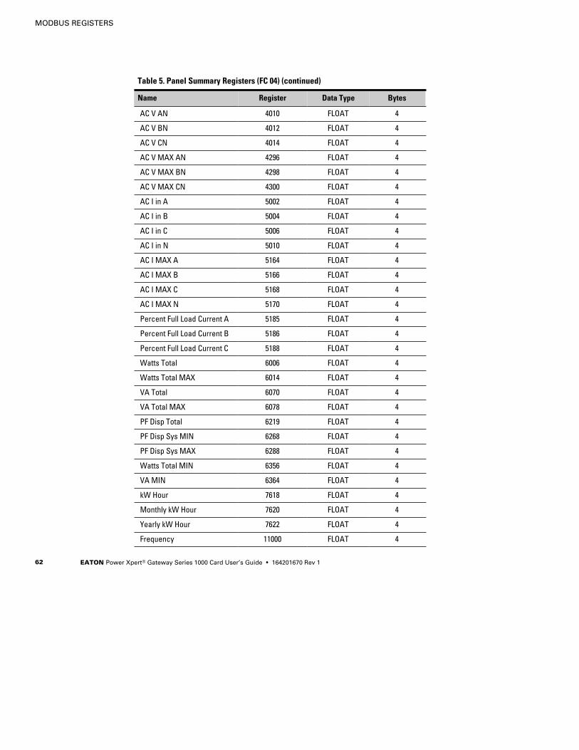
Table 5 shows the registers that contain summary data for the panel.The registers contain the total information for all the breakers in thepanel.

MODBUS REGISTERS
EATON Power Xpert® Gateway Series 1000 Card User’s Guide S 164201670 Rev 1 61
For example, the AC Voltage between Phase A and Neutral is availablein register 4010. To read the AC Voltage in Phase A at Panel #1, set theModbus program to Unit ID 2 and register 4010:
IP: <IP address of PDU/RPP>Unit ID: 2Starting Register: 4010Number of Registers: 2Function Code: 04
To read the AC Voltage in Phase A at Panel #4, set the Modbus programto Unit ID 5 and register 4010:
IP: <IP address of PDU/RPP>Unit ID: 5Starting Register: 4010Number of Registers: 2Function Code: 04
Table 5. Panel Summary Registers (FC 04)
Name Register Data Type Bytes
Display Template 1000 UINT 2
Vendor Name 1001 STRING 64
Model Name 1033 STRING 64
Display Name 1065 STRING 64
Serial Number 1123 STRING 64
Device Volts Rating 1202 UINT 4
Number of Phases 1208 UINT 2
Asset ID 1324 STRING 128
Breaker Rating 1453 UINT 2
Breaker Warning 1456 UINT 2
Breaker Overload 1457 UINT 2
Neutral Current Alarm 1459 UINT 2
Enter Admin State 3047 UINT 2
Enter Operating State 3048 UINT 2
Enter Readiness State 3049 UINT 2
Enter Alarm State 3050 UINT 2
Enter Standby State 3051 UINT 2
MODBUS REGISTERS
EATON Power Xpert® Gateway Series 1000 Card User’s Guide S 164201670 Rev 162
Table 5. Panel Summary Registers (FC 04) (continued)
BytesData TypeRegisterName
AC V AN 4010 FLOAT 4
AC V BN 4012 FLOAT 4
AC V CN 4014 FLOAT 4
AC V MAX AN 4296 FLOAT 4
AC V MAX BN 4298 FLOAT 4
AC V MAX CN 4300 FLOAT 4
AC I in A 5002 FLOAT 4
AC I in B 5004 FLOAT 4
AC I in C 5006 FLOAT 4
AC I in N 5010 FLOAT 4
AC I MAX A 5164 FLOAT 4
AC I MAX B 5166 FLOAT 4
AC I MAX C 5168 FLOAT 4
AC I MAX N 5170 FLOAT 4
Percent Full Load Current A 5185 FLOAT 4
Percent Full Load Current B 5186 FLOAT 4
Percent Full Load Current C 5188 FLOAT 4
Watts Total 6006 FLOAT 4
Watts Total MAX 6014 FLOAT 4
VA Total 6070 FLOAT 4
VA Total MAX 6078 FLOAT 4
PF Disp Total 6219 FLOAT 4
PF Disp Sys MIN 6268 FLOAT 4
PF Disp Sys MAX 6288 FLOAT 4
Watts Total MIN 6356 FLOAT 4
VA MIN 6364 FLOAT 4
kW Hour 7618 FLOAT 4
Monthly kW Hour 7620 FLOAT 4
Yearly kW Hour 7622 FLOAT 4
Frequency 11000 FLOAT 4

MODBUS REGISTERS
EATON Power Xpert® Gateway Series 1000 Card User’s Guide S 164201670 Rev 1 63
Table 5. Panel Summary Registers (FC 04) (continued)
BytesData TypeRegisterName
MIN Frequency 11022 FLOAT 4
MAX Frequency 11027 FLOAT 4
Panel Alarms (FC 01 or 02)Table 6 lists the panel alarms. They are not registers, but are discreteinputs and are read using FC 01 or FC 02.
To read the Main Breaker Overload alarm at Panel #4, set the Modbusprogram to Unit ID 5 and coil address 1254:
IP: <IP address of PDU/RPP>Unit ID: 5Starting Register: 1254Number of Registers: 1Function Code: 02
Table 6. Panel Alarms (FC 01 or 02)
Name Coil/Status Address Data Type
Neutral Overload 1219 BOOL
Panel Under Voltage 1238 BOOL
Panel Over Voltage 1242 BOOL
Panel Under Over Frequency 1248 BOOL
Branch Breaker Overload Warning 1249 BOOL
Branch Breaker Overload 1250 BOOL
Main Breaker Overload Warning 1253 BOOL
Main Breaker Overload 1254 BOOL
MODBUS REGISTERS
EATON Power Xpert® Gateway Series 1000 Card User’s Guide S 164201670 Rev 164
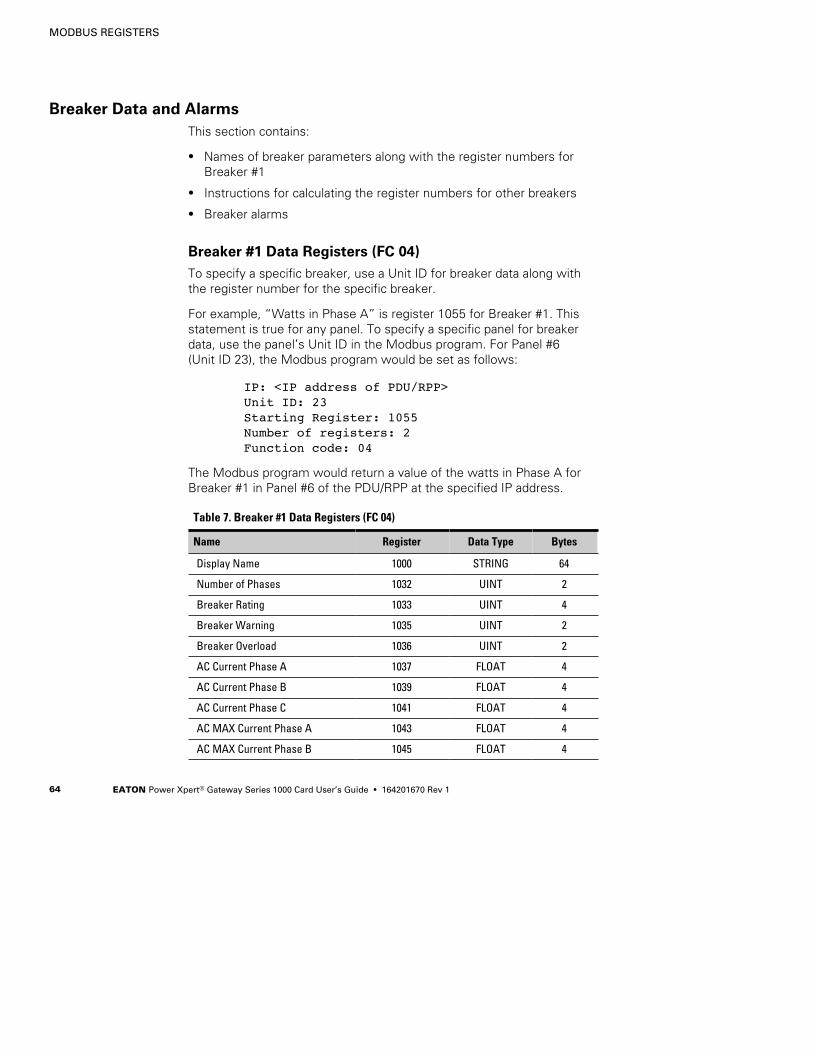
Breaker Data and AlarmsThis section contains:
S Names of breaker parameters along with the register numbers forBreaker #1
S Instructions for calculating the register numbers for other breakers
S Breaker alarms
Breaker #1 Data Registers (FC 04)To specify a specific breaker, use a Unit ID for breaker data along withthe register number for the specific breaker.
For example, “Watts in Phase A” is register 1055 for Breaker #1. Thisstatement is true for any panel. To specify a specific panel for breakerdata, use the panel’s Unit ID in the Modbus program. For Panel #6(Unit ID 23), the Modbus program would be set as follows:
IP: <IP address of PDU/RPP>Unit ID: 23Starting Register: 1055Number of registers: 2Function code: 04
The Modbus program would return a value of the watts in Phase A forBreaker #1 in Panel #6 of the PDU/RPP at the specified IP address.
Table 7. Breaker #1 Data Registers (FC 04)
Name Register Data Type Bytes
Display Name 1000 STRING 64
Number of Phases 1032 UINT 2
Breaker Rating 1033 UINT 4
Breaker Warning 1035 UINT 2
Breaker Overload 1036 UINT 2
AC Current Phase A 1037 FLOAT 4
AC Current Phase B 1039 FLOAT 4
AC Current Phase C 1041 FLOAT 4
AC MAX Current Phase A 1043 FLOAT 4
AC MAX Current Phase B 1045 FLOAT 4

MODBUS REGISTERS
EATON Power Xpert® Gateway Series 1000 Card User’s Guide S 164201670 Rev 1 65
Table 7. Breaker #1 Data Registers (FC 04) (continued)
BytesData TypeRegisterName
AC MAX Current Phase C 1047 FLOAT 4
Percent FL Current A 1049 FLOAT 4
Percent FL Current B 1051 FLOAT 4
Percent FL Current C 1053 FLOAT 4
Watts Phase A 1055 FLOAT 4
Watts Phase B 1057 FLOAT 4
Watts Phase C 1059 FLOAT 4
Watts Phase A MAX 1061 FLOAT 4
Watts Phase B MAX 1063 FLOAT 4
Watts Phase C MAX 1065 FLOAT 4
VA Phase A 1067 FLOAT 4
VA Phase B 1069 FLOAT 4
VA Phase C 1071 FLOAT 4
VA Phase A MAX 1073 FLOAT 4
VA Phase B MAX 1075 FLOAT 4
VA Phase C MAX 1077 FLOAT 4
PF Displacement Phase A 1079 FLOAT 4
PF Displacement Phase B 1081 FLOAT 4
PF Displacement Phase C 1083 FLOAT 4
PF Displacement A Minimum 1085 FLOAT 4
PF Displacement B Minimum 1087 FLOAT 4
PF Displacement C Minimum 1089 FLOAT 4
PF Displacement A Maximum 1091 FLOAT 4
PF Displacement A Maximum 1093 FLOAT 4
PF Displacement A Maximum 1095 FLOAT 4
kW Hours 1097 FLOAT 4
kW Hours Monthly 1099 FLOAT 4
kW Hours Yearly 1101 FLOAT 4

MODBUS REGISTERS
EATON Power Xpert® Gateway Series 1000 Card User’s Guide S 164201670 Rev 166
Calculating Breaker Register NumbersTable 7 shows the register numbers for Breaker #1. There can be manybreakers in a panel. Determine the corresponding register numbers forother breakers in the panel by using the following formula:
Breaker register # = Breaker #1 register + ((Breaker # – 1) x 200))
For example:Breaker #2 starts at 1200: 1000 + ((2 – 1) x 200)
1000 + (1 x 200)1000 + 2001200
Breaker #3 starts at 1400: 1000 + ((3 – 1) x 200)1000 + (2 x 200)1000 + 4001400
Breaker #14 starts at 3600: 1000 + ((14 – 1) x 200)1000 + (13 x 200)1000 + 26003600
This formula works for any register. For example, for Breaker #1, theregister number of “Watts Phase A” is 1055. The correspondingaddress for Breaker #18 is:
1055 + ((18 – 1) x 200)1055 + (17 x 200)1055 + 34004455

MODBUS REGISTERS
EATON Power Xpert® Gateway Series 1000 Card User’s Guide S 164201670 Rev 1 67
Breaker Alarms (FC 01 or 02)There are two alarms for each circuit breaker: Overload Warning andOverload. Each alarm has a unique address similar to the data registers,but these alarms are not data registers. The alarms are discrete inputsand are read using FC 01 or FC 02 in the Modbus program.
Table 8. Breaker Alarms (FC 01 or 02)
Name Coil/Status Address Data Type
Branch Breaker 1 Overload Warning 1000 BOOL
Branch Breaker 1 Overload 1001 BOOL
Table 8 shows the alarms for Breaker #1. Determine the correspondingalarms for other breakers by using the following formula:
Breaker #5 address = ((Breaker number – 1) x 2) + Breaker #1 address
For example, to find the Overload Warning alarm address for Breaker #5:
Breaker #5 Overload Warning = ((5 – 1) x 2) + 1000= ((4) x 2) + 1000= (8) + 1000= 1008
To find the Overload alarm address for Breaker #20:
Breaker #20 Overload = ((20 – 1) x 2) + 1001= ((19) x 2) + 1001= (38) + 1001= 1039
To read the Overload Warning alarm for Breaker #5 in Panel #8, theModbus program would be set as follows:
IP: <IP address of PDU/RPP>Unit ID: 25Starting Register: 1008Number of registers: 1Function code: 02
The Modbus program would return a true/false value of the OverloadWarning alarm for Breaker #5 in Panel #8 of the PDU/RPP at thespecified IP address.

MODBUS REGISTERS
EATON Power Xpert® Gateway Series 1000 Card User’s Guide S 164201670 Rev 168
Environmental Monitoring Probe (FC 03 or 04)The optional Environmental Monitoring Probe for the PDU/RPP canmeasure temperature and humidity. Because the device can be locatedoutside the PDU/RPP, the reference is to “auxiliary” data. In addition, itcontains two connections for monitoring the condition of auxiliary inputcontacts, such as a door switch. See Table 9 for a list of EMP registers.
An exception code is returned if the EMP is not installed.
To read the temperature at the PDU/RPP, set the Modbus program toUnit ID 254 and coil address 12028:
IP: <IP address of PDU/RPP>Unit ID: 254Starting Register: 12028Number of registers: 2Function Code: 04
Table 9. Environmental Monitor (FC 03 or 04)
Name Register Data Type Bytes
Vendor Name 1001 STRING 64
Model Name 1033 STRING 64
Display Name 1065 STRING 64
Serial Number 1123 STRING 64
Device ID 1099 UINT 4
Auxiliary Input 1 10275 UINT 2
Auxiliary Input 2 10276 UINT 2
Auxiliary Temperature 12028 FLOAT 4
Auxiliary Humidity 12030 FLOAT 4
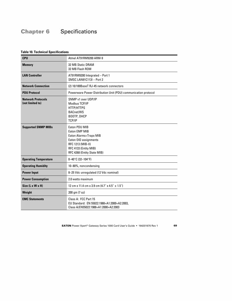
EATON Power Xpert® Gateway Series 1000 Card User’s Guide S 164201670 Rev 1 69
Chapter 6 Specifications
Table 10. Technical Specifications
CPU Atmel AT91RM9200 ARM-9
Memory 32 MB Static DRAM32 MB Flash ROM
LAN Controller AT91RM9200 Integrated – Port 1SMSC LAN91C113I – Port 2
Network Connection (2) 10/100BaseT RJ-45 network connectors
PDU Protocol Powerware Power Distribution Unit (PDU) communication protocol
Network Protocols(not limited to)
SNMP v1 over UDP/IPModbus TCP/IPHTTP/HTTPSBACnet/WSBOOTP, DHCPTCP/IP
Supported SNMP MIBs Eaton PDU MIBEaton EMP MIBEaton Alarms+Traps MIBEaton OID assignmentsRFC 1213 (MIB-II)RFC 4133 (Entity MIB)RFC 4268 (Entity State MIB)
Operating Temperature 0–40°C (32–104°F)
Operating Humidity 10–80%, noncondensing
Power Input 8–25 Vdc unregulated (12 Vdc nominal)
Power Consumption 2.0 watts maximum
Size (L x W x H) 12 cm x 11.4 cm x 3.9 cm (4.7” x 4.5” x 1.5”)
Weight 200 gm (7 oz)
EMC Statements Class A: FCC Part 15EU Standard: EN 55022:1988+A1:2000+A2:2003,Class A/EN55022:1988+A1:2000+A2:2003

SPECIFICATIONS
EATON Power Xpert® Gateway Series 1000 Card User’s Guide S 164201670 Rev 170

EATON Power Xpert® Gateway Series 1000 Card User’s Guide S 164201670 Rev 1 71
Chapter 7 Operation and Maintenance
This section explains:
S Indicator descriptions
S DIP switch settings
S Generating log files
S Firmware upgrade instructions
Front-Panel Indicator DescriptionsThe Ethernet port indicator descriptions for the PXGX Series 1000 Cardare listed in Table 11; the stacked indicator descriptions are listed inTable 12.
Table 11. Ethernet Port Indicators
Indicator Label Illuminated Not Illuminated
Ethernet Port 1 100 Indicates a valid 100 Mb Connection(Link).
Indicates a valid 10 Mb Connection (Link)as long as the corresponding ACTindicator is illuminated.
ACT Indicates network activity when theindicator is on or blinking.
Indicates network activity when theindicator is on or blinking.
Ethernet Port 2 100 Indicates a valid 100 Mb Connection(Link).
Indicates a valid 10 Mb Connection (Link)as long as the corresponding ACTindicator is illuminated.
ACT Indicates network activity when theindicator is on or blinking.
Indicates network activity when theindicator is on or blinking.

OPERATION AND MAINTENANCE
EATON Power Xpert® Gateway Series 1000 Card User’s Guide S 164201670 Rev 172
Table 12. Stacked Indicator Descriptions
Label Color Illuminated Not Illuminated
STATUS Green Communication with the PDU has beenestablished.
Communication with the PDU has notbeen established. As the card boots, theindicator remains off. However, if itremains off after one minute, there is acommunication problem between thecard and the PDU.
DHCP Amber At least one port is configured for DHCPand has obtained IP address information.
The use of DHCP/BOOTP has beendisabled by the user, or all portsconfigured for DHCP have failed to obtainIP address information.
IDENT Red A firmware update is in progress. Do notremove the card from the PDU.
A firmware update is not in progress.
POWER Green DC power is available to the card fromthe PDU.
If all indicators are not illuminated, DCpower is not available from the PDU. Thismay indicate that the PDU is off andunplugged.
NOTE During the power-on sequence, all four indicators are illuminated for approximately 20 seconds. Wait at leastone minute for the card’s boot process to complete before comparing the indicators to the table above becauseindicators may turn on and off at different times in the boot process.

OPERATION AND MAINTENANCE
EATON Power Xpert® Gateway Series 1000 Card User’s Guide S 164201670 Rev 1 73
DIP Switch DescriptionDIP switch definitions for the PXGX Series 1000 Card are listed inTable 13.
Table 13. DIP Switch Definitions
S1 PositionNumber
OFF Position (Default) ON Position
1 Enable previously stored networkconfiguration settings (Normalmode)
Override network settings toassign private IP addresses(Configuration mode); Port 1 is setto 192.168.1.1 and Port 2 is set to192.168.1.2
2 Enable the front panel RJ-45 forserial communication
Enable the front panel RJ-45 portfor communication with anEnvironmental Monitoring Probe(EMP) device for immediate orfuture use
3 Normal behavior Reset the HTTP passwords to thedefaults on boot (user andadmin). After a successful boot,the switch should be turned backoff before rebooting the card.
4 Reserved Reserved
5 Reserved Reserved
6 Normal behavior Reset the card to factory defaultson boot (after a successful boot,the switch should be turned backoff before rebooting the card)

OPERATION AND MAINTENANCE
EATON Power Xpert® Gateway Series 1000 Card User’s Guide S 164201670 Rev 174
Generating Log Files
NOTE The data log and event log files are comma-separated values (*.csv) files that can
be opened in Microsoft Excel software. Some computer configurations will automatically
open the files in the Microsoft Excel software instead of prompting you to save.
To generate a data log:
1. From the card’s Web page, click the Data Log link from the menubar.
2. Click the Click to generate button.
3. Select a name and location for the file (if prompted to save).
To generate an event log:
1. From the card’s Web page, click the Event Log link from the menubar.
2. Click the Click to generate button.
3. Select a name and location for the file (if prompted to save).
Upgrading the Card’s FirmwareThe card’s firmware may be updated by downloading the appropriate filefrom www.eaton.com/powerxpert. During the upgrade process, thePXGX Series 1000 Card does not monitor the PDU status.
To upgrade the firmware:
1. From the card’s Web page, click the Firmware link from the menubar.
2. Click the Browse button.
3. Download the pxgx_pdu_xxx.rom firmware file, available on theWeb at www.eaton.com/powerxpert.
4. After updating the firmware, the card prompts you to reboot. ClickOK to reboot the card. An audible alarm sounds as the card reboots,and the Web page shows the “Gateway rebooting, please wait...”message. The Web page refreshes after approximately 75 seconds.

EATON Power Xpert® Gateway Series 1000 Card User’s Guide S 164201670 Rev 1 75
Chapter 8 Service and Support
If you have any questions or problems with the PXGX Series 1000 Card,call your Local Distributor or the Help Desk at one of the followingtelephone numbers and ask for a PXGX Series 1000 Card technicalrepresentative.
United States: 1-800-843-9433 or 1-919-870-3028Canada: 1-800-461-9166 ext 260All other countries: Call your local service representative
Please have the following information ready when you call the HelpDesk:
S Model number
S Serial number
S Version number (if available)
S Date of failure or problem
S Symptoms of failure or problem
S Customer return address and contact information
If repair is required, you will be given a Returned Material Authorization(RMA) Number. This number must appear on the outside of the packageand on the Bill Of Lading (if applicable). Use the original packaging orrequest packaging from the Help Desk or distributor. Units damaged inshipment as a result of improper packaging are not covered underwarranty. A replacement or repair unit will be shipped, freight prepaid forall warrantied units.
NOTE For critical applications, immediate replacement may be available. Call the HelpDesk for the dealer or distributor nearest you.

SERVICE AND SUPPORT
EATON Power Xpert® Gateway Series 1000 Card User’s Guide S 164201670 Rev 176
Two-Year Limited Warranty (US and Canada)
Power Xpert Gateway (PXGX) Series 1000 and Series 2000 CardsWARRANTOR: The warrantor for the limited warranties set forth herein is Eaton Electrical Inc., a DelawareCorporation company (“Company”).
LIMITED WARRANTY: This limited warranty (this “Warranty”) applies only to the original End-User (the “End-User”)of the Power Xpert Gateway (PXGX) Series 1000 or Series 2000 Card (the “Product”) purchased on or after June 1,2004 and cannot be transferred. This Warranty applies even in the event that the Product is initially sold byCompany for resale to an End-User.
LIMITED WARRANTY PERIOD: The period covered by this Warranty for the Product installed [and currently located]in the fifty (50) United States, the District of Columbia, and Canada is twenty-four (24) months from the date ofpurchase.
WHAT THIS LIMITED WARRANTY COVERS: The warrantor warrants that the Product (the “Warranted Item”) is freefrom defects in material and workmanship. If, in the opinion of Company, a Warranted Item is defective and thedefect is within the terms of this Warranty, Company’s sole obligation will be to repair or replace such defectiveWarranted Item (including by providing service, parts and labor, as applicable), at the option of Company.
PROCEDURES FOR REPAIR OR REPLACEMENT OF WARRANTED ITEMS: The Warranted Item will be repaired orreplaced at a Company site or such other location as determined by Company.
If the Warranted Item is to be replaced by Company, and the End-User supplies a credit card number or purchaseorder for the value of the replacement Product, Company will use commercially reasonable business efforts to ship(via standard ground shipment and at no cost to the End-User) the replacement Warranted Item to the End-Userwithin one (1) business day after Company receives notice of the warranty claim. In such case, the End-User mustreturn (at Company’s expense) the defective Warranted Item to Company in the same packaging as thereplacement Warranted Item received by the End-User or as otherwise instructed by Company. If Company doesnot receive the defective Warranted Item, Company will either charge the End-User’s credit card, or send theEnd-User an invoice (which the End-User agrees to pay), for the value of the replacement Product.
If the Warranted Item is to be replaced by Company, but the End-User is unwilling or unable to supply a credit cardnumber or purchase order for the value of the replacement Product, Company will use commercially reasonablebusiness efforts to ship (via standard ground shipment and at no cost to the End-User) the replacement WarrantedItem to the End-User within one (1) business day after Company receives the defective Product from the End-User.
In any case, Company will provide shipping instructions and will pay its designated carrier for all shipping charges forreturn of defective equipment and replacement of Warranted Items. Any returned Warranted Item or parts that arereplaced may be new or reconditioned. All Warranted Items returned to Company and all parts replaced byCompany shall become the property of Company.
WHAT THIS LIMITED WARRANTY DOES NOT COVER: This Warranty does not cover any defects or damagescaused by: (a) failure to properly store the Product before installation; (b) shipping and delivery of the Product ifshipping is FOB Factory; (c) neglect, accident, abuse, misuse, misapplication, or incorrect installation; (d) repair oralteration not authorized in writing by Company personnel or performed by an authorized Company CustomerService Engineer or Agent; (e) improper testing, operation, maintenance, adjustment, or modification of any kind notauthorized in writing by Company personnel or performed by an authorized Company Customer Service Engineer orAgent; or (f) use of the Product under other than normal operating conditions or in a manner inconsistent with theProduct’s labels or instructions.
This Warranty is not valid if the Product’s serial numbers have been removed or are illegible. Any Warranted Itemsrepaired or replaced pursuant to this Warranty will be warranted for the remaining portion of the original Warrantysubject to all the terms thereof.

SERVICE AND SUPPORT
EATON Power Xpert® Gateway Series 1000 Card User’s Guide S 164201670 Rev 1 77
Company shall not be responsible for any charges for testing, checking, removal or installation of Warranted Items.
COMPANY DOES NOT WARRANT EQUIPMENT NOT MANUFACTURED BY COMPANY. IF PERMITTED BY THEAPPLICABLE MANUFACTURER, COMPANY SHALL PASS THROUGH SUCH MANUFACTURER’S WARRANTIES TOEND-USER.
COMPANY DOES NOT WARRANT SOFTWARE (IF APPLICABLE TO THE PRODUCT), INCLUDING SOFTWAREEMBEDDED IN PRODUCTS, THAT IS NOT CREATED BY COMPANY. WITHOUT LIMITING THE FOREGOING,COMPANY SPECIFICALLY DOES NOT WARRANT SOFTWARE (SUCH AS LINUX®) THAT WAS CREATED USING AN“OPEN SOURCE” MODEL OR IS DISTRIBUTED PURSUANT TO AN OPEN SOURCE LICENSE.
THIS WARRANTY IS THE SOLE AND EXCLUSIVE WARRANTY OFFERED BY COMPANY WITH RESPECT TO THEPRODUCTS AND SERVICES AND, EXCEPT FOR SUCH FOREGOING WARRANTY COMPANY DISCLAIMS ALL OTHERWARRANTIES INCLUDING BUT NOT LIMITED TO ANY IMPLIED WARRANTIES OF MERCHANTABILITY, TITLE,NON-INFRINGEMENT, AND FITNESS FOR A PARTICULAR PURPOSE. CORRECTION OF NON-CONFORMITIES INTHE MANNER AND FOR THE PERIOD OF TIME PROVIDED ABOVE SHALL CONSTITUTE COMPANY’S SOLELIABILITY AND END-USER’S EXCLUSIVE REMEDY FOR FAILURE OF COMPANY TO MEET ITS WARRANTYOBLIGATIONS, WHETHER CLAIMS OF THE END-USER ARE BASED IN CONTRACT, IN TORT (INCLUDINGNEGLIGENCE OR STRICT LIABILITY), OR OTHERWISE.
LIMITATION OF LIABILITY: The remedies of the End-User set forth herein are exclusive and are the sole remediesfor any failure of Company to comply with its obligations hereunder. In no event shall Company be liable in contract,in tort (including negligence or strict liability) or otherwise for damage to property or equipment other than theProducts, including loss of profits or revenue, loss of use of Products, loss of data, cost of capital, claims ofcustomers of the End-User or any special, indirect, incidental or consequential damages whatsoever. The totalcumulative liability of Company hereunder whether the claims are based in contract (including indemnity), in tort(including negligence or strict liability) or otherwise, shall not exceed the price of the Product on which such liabilityis based.
Company shall not be responsible for failure to provide service or parts due to causes beyond Company’sreasonable control.
END-USER’S OBLIGATIONS: In order to receive the benefits of this Warranty, the End-User must use the Productin a normal way; follow the Product’s user’s guide; and protect against further damage to the Product if there is acovered defect.
OTHER LIMITATIONS: Company’s obligations under this Warranty are expressly conditioned upon receipt byCompany of all payments due to it (including interest charges, if any). During such time as Company has notreceived payment of any amount due to it for the Product, in accordance with the contract terms under which theProduct is sold, Company shall have no obligation under this Warranty. Also during such time, the period of thisWarranty shall continue to run and the expiration of this Warranty shall not be extended upon payment of anyoverdue or unpaid amounts.
COSTS NOT RELATED TO WARRANTY: The End-User shall be invoiced for, and shall pay for, all services notexpressly provided for by the terms of this Warranty, including without limitation, site calls involving an inspectionthat determines no corrective maintenance is required. Any costs for replacement equipment, installation, materials,freight charges, travel expenses or labor of Company representatives outside the terms of this Warranty will beborne by the End-User.
OBTAINING WARRANTY SERVICE: In the USA, call the Customer Reliability Center 7x24 at 800-356-5737. Outsideof the USA, contact your local Eaton product sales or service representative, or call the Customer Reliability Centerin the USA at 919-870-3149. For comments or questions about this Warranty, write to the Customer QualityRepresentative, 3301 Spring Forest Road, Raleigh, North Carolina 27616 USA.

SERVICE AND SUPPORT
EATON Power Xpert® Gateway Series 1000 Card User’s Guide S 164201670 Rev 178


*1642016701*164201670 1