power transmission-belt drives and bearing selection tutor ... · pdf filepower...
TRANSCRIPT
Page 0 of 38
12/13/2014
Bachelor of Engineering Technology | By: Yahya Saif - ID:201001047
PROJECT
4(ENB6907) POWER TRANSMISSION-BELT DRIVES AND BEARING SELECTION
TUTOR: DR. SUBRAMANIAN CHITHAMBARAM

Page 1 of 38
Contents Deciding motor specification (power and input velocity): ......................................................................................................................................... 4
Size and selection of pulleys and belt drives: ............................................................................................................................................................ 5
Calculating the size of the pulleys: ............................................................................................................................................................................ 5
Calculating pitch length: ............................................................................................................................................................................................ 6
Calculating belt length: (theoretical) ......................................................................................................................................................................... 7
Corrected centre to centre distance, actual belt length and correction factor (from tables): ................................................................................... 7
Calculating angle of contact: ..................................................................................................................................................................................... 7
Type of belts: ............................................................................................................................................................................................................. 7
Finding the number of belts required: ...................................................................................................................................................................... 8
Design specifications: ................................................................................................................................................................................................ 9
Pulleys design: ......................................................................................................................................................................................................... 10
Design of Shaft: ....................................................................................................................................................................................................... 12
The coefficient of friction between the belt and pulley: ......................................................................................................................................... 12
Mass of the larger pulley: ........................................................................................................................................................................................ 12
Velocity of the belt: ................................................................................................................................................................................................. 12
Design givens:.......................................................................................................................................................................................................... 12
Tension calculations: ............................................................................................................................................................................................... 13
Finding the maximum bending moment: ................................................................................................................................................................ 16
The torque on the shaft: ......................................................................................................................................................................................... 17
Shear force and bending moment diagrams: .......................................................................................................................................................... 18
Shear force and bending moment diagram for vertical forces: ............................................................................................................................... 18
Shear force and bending moment diagram for vertical forces: ............................................................................................................................... 19
Equivalent torque: ................................................................................................................................................................................................... 20
Calculating shaft diameter and shaft material selection ......................................................................................................................................... 20
Size and selection of bearings: ................................................................................................................................................................................ 21
Forces on the bearing: ............................................................................................................................................................................................. 21
Selecting type of bearing: ........................................................................................................................................................................................ 21
Research part .......................................................................................................................................................................................................... 24
Works Cited ............................................................................................................................................................................................................. 35
Appendix (A) ............................................................................................................................................................................................................ 37
Appendix (B) ............................................................................................................................................................................................................ 38

Page 2 of 38
Table of figures Figure 1, Hack saw motor specifications. [1] ............................................................................................................................................................. 4
Figure 5, Service factor [3] ........................................................................................................................................................................................ 5
Figure 3, minimum pulley diameter table [3] ............................................................................................................................................................ 6
Figure 2, dimensions of an open belt drive [3] .......................................................................................................................................................... 6
Figure 4, dimensions of an open belt drive [2] ......................................................................................................................................................... 6
Figure 6, dimensions of an open belt drive [3] .......................................................................................................................................................... 8
Figure 7, dimensions of an open belt drive [3] .......................................................................................................................................................... 8
Figure 8, dimensions of the SPB belts based on British standards [5] ....................................................................................................................... 9
Figure 9, pulleys, belt, shafts, bearings, motor, bolt design (Isometric) .................................................................................................................. 10
Figure 11, pulleys, belt, shafts, bearings, motor, bolt design (front side view) ....................................................................................................... 10
Figure 12, pulleys, belt, shafts, bearings, motor, bolts design (Right side view) ..................................................................................................... 10
Figure 13, Pulley with pin inside (prevent backward and forward mobment), pull tic connected with motor shaft ............................................... 11
Figure 14, Pulley with pin inside (prevent backward and forward mobment), also the shaft is fited by the bearings ............................................ 11
Figure 15, shaft supported by a roller bearing (the shown cylinders are for the two bearings) .............................................................................. 11
Figure 16, pulley front side ...................................................................................................................................................................................... 11
Figure 17, shaft supported by a roller bearing (the shown cylinders are for the two bearings) .............................................................................. 11
Figure 18, pulley back side ...................................................................................................................................................................................... 11
Figure 19, coefficient of friction for belts and pulleys [3] ........................................................................................................................................ 12
Figure 21, mass of the bigger pulley (13.81Kg) ........................................................................................................................................................ 12
Figure 22, Belt inertial force and centrifugal tension [5] ......................................................................................................................................... 13
Figure 23, total tension on belt [33] ........................................................................................................................................................................ 13
Figure 24, vertical and horizontal components ....................................................................................................................................................... 14
Figure 25, forces act on the shaft ............................................................................................................................................................................ 15
Figure 26, FBD of the shaft front view (vertical forces) ........................................................................................................................................... 15
Figure 28, FBD of the shaft top view (horizontal forces) ......................................................................................................................................... 15
Figure 30, free body diagram, shear force and bending moment diagram (for vertical forces) [31] ....................................................................... 18
Figure 31, free body diagram, shear force and bending moment diagram (for horizontal forces) [31] .................................................................. 19
Figure 32, FBD of the shaft (for the resultant force)................................................................................................................................................ 21
Figure 34, FBD of the shaft (for the resultant force) [8] .......................................................................................................................................... 22
Figure 36, Selected bearing for bearing A [10] ........................................................................................................................................................ 23
Figure 38, Selected bearing for bearing B [11] ........................................................................................................................................................ 23
Figure 40, Ball bearing construction [32] ................................................................................................................................................................. 24
Figure 41, Straight Roller bearing [32] ..................................................................................................................................................................... 25
Figure 42, Needle Roller bearing [32] ...................................................................................................................................................................... 25
Figure 43, Tapered Roller bearing [32] .................................................................................................................................................................... 26
Figure 44, Spherical Roller [16] Bearings ................................................................................................................................................................ 26
Figure 45, Ball thrust bearing [32] ........................................................................................................................................................................... 26
Figure 46, Drive chain. [20] ..................................................................................................................................................................................... 27
Figure 47, Motion of a chain [20] ............................................................................................................................................................................ 28
Figure 48, motion of chain [20] ............................................................................................................................................................................... 28
Figure 49, the roller chain. [21] .............................................................................................................................................................................. 29
Figure 50, the inverted tooth or silent chain [21] .................................................................................................................................................... 29
Figure 51, Bush chain [2] ......................................................................................................................................................................................... 29
Page 3 of 38
Figure 52, hoisting and hauling chains [3] ............................................................................................................................................................... 30
Figure 53, Conveyor chains [3] ................................................................................................................................................................................ 30
Figure 54, friction plate clutch [24] ......................................................................................................................................................................... 31
Figure 55, Cone clutch [24] ...................................................................................................................................................................................... 32
Figure 56, Expanding Shoe Clutch [24] .................................................................................................................................................................... 32
Figure 57, Jaw Clutch [24] ....................................................................................................................................................................................... 33
Figure 58, expanding-shoe centrifugal clutch [24] .................................................................................................................................................. 33
Figure 59, overriding clutch [24] ............................................................................................................................................................................. 34
Figure 60, tension force on the pulley ..................................................................................................................................................................... 37
Figure 62, Ball bearing types [8] .............................................................................................................................................................................. 38
Figure 63, Roller bearing types [8]........................................................................................................................................................................... 38
Table of tables Table 1, corrected centre to centre distance [3] ....................................................................................................................................................... 7
Table 2, design specifications [5] ............................................................................................................................................................................... 9
Table 3, SPB belts design dimensions (British standards) [5] ..................................................................................................................................... 9
Table 4, design givens ............................................................................................................................................................................................. 12
Table 5, summary of forces ..................................................................................................................................................................................... 16
Table 6, summary of forces act on the reaction Ra and Rb (bearings) .................................................................................................................... 17
Table 7, summary of forces act on shaft ................................................................................................................................................................. 17
Table 8, forces act on each bearing ......................................................................................................................................................................... 21
Table 9, Selected bearing for bearing A [10] ........................................................................................................................................................... 23
Table 10, Selected bearing for bearing B [11].......................................................................................................................................................... 23
Table 11, Advantages and disadvantages of chains [2] ........................................................................................................................................... 27
Page 4 of 38
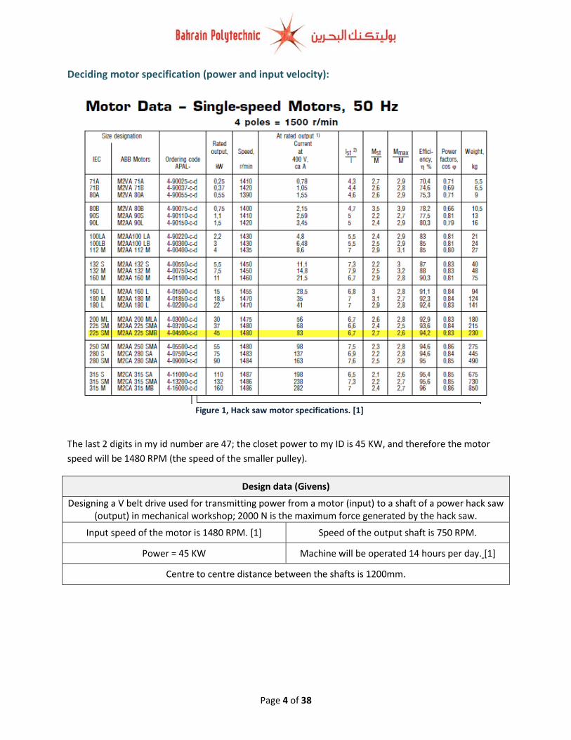
Deciding motor specification (power and input velocity):
The last 2 digits in my id number are 47; the closet power to my ID is 45 KW, and therefore the motor
speed will be 1480 RPM (the speed of the smaller pulley).
Design data (Givens)
Designing a V belt drive used for transmitting power from a motor (input) to a shaft of a power hack saw (output) in mechanical workshop; 2000 N is the maximum force generated by the hack saw.
Input speed of the motor is 1480 RPM. [1] Speed of the output shaft is 750 RPM.
Power = 45 KW Machine will be operated 14 hours per day. [1]
Centre to centre distance between the shafts is 1200mm.
Figure 1, Hack saw motor specifications. [1]
Page 5 of 38
Figure 2, Service factor [3]�
Size and selection of pulleys and belt drives: Note: most of the used formulas in this section are taken from “Theory of machine by R.S.Khurmi” book,
and from fenner wedge belt drive selection catalogue.
1. Calculating the size of the pulleys:
Finding the speed ratio:
𝑆𝑝𝑒𝑒𝑑 𝑟𝑎𝑡𝑖𝑜 = 𝑁1
𝑁2=
1480
750= 1.97: 1 [2]�
Finding Service factor: we can assume that the working of the power hack saw is close to saw mill;
so I will assume that the class of power hack saw is medium also, we can assume that the prime
movers are not fitted with soft start device; so the hacksaw has a heavy start.. From the figure
below the service factor is equal to 1.3.
Design power:
Power = Motor power × FOS = 45 × 1.3 = 58.5 KW [3]�
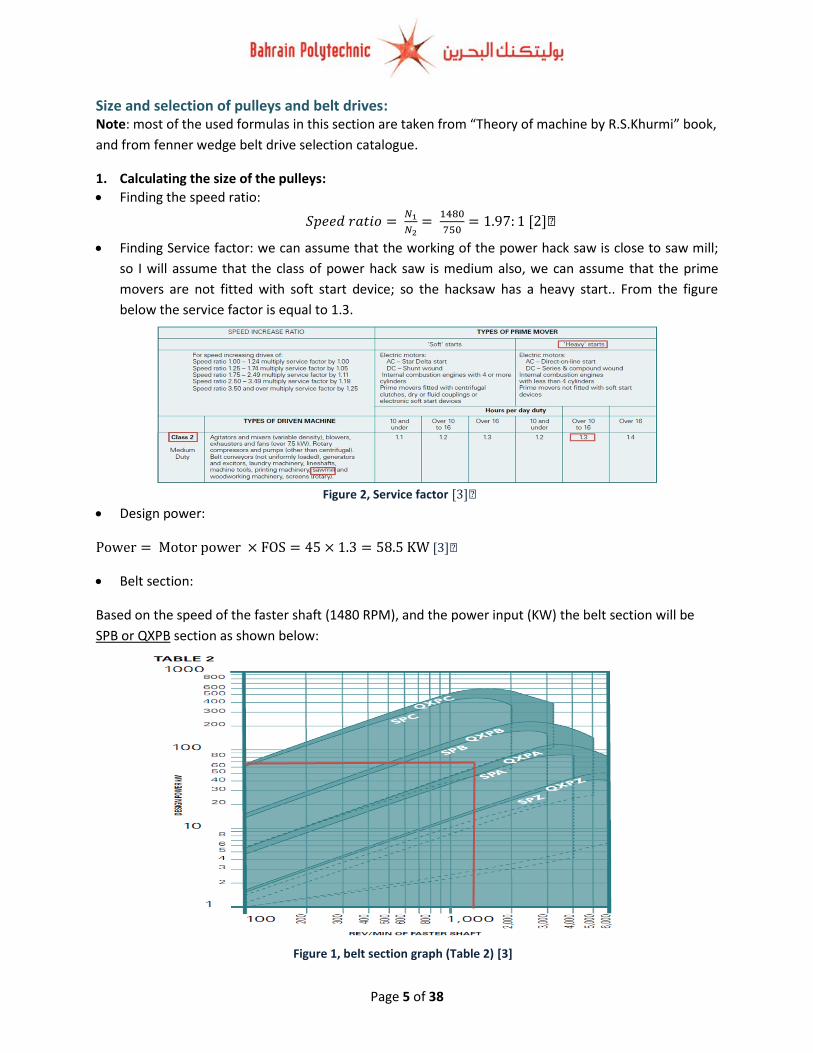
Belt section:
Based on the speed of the faster shaft (1480 RPM), and the power input (KW) the belt section will be
SPB or QXPB section as shown below:
Figure 1, belt section graph (Table 2) [3]

Page 6 of 38
Figure 3, minimum pulley diameter table [3]
Figure 5, dimensions of an open belt drive [2]�
Figure 4, dimensions of an open belt drive [3]
Minimum pulley size:
From the figure below; the minimum diameter for the smaller pulley is 160 mm. I select the size of the
pulley based on the speed of faster shaft (I select 1800 RPM instead of 1440 RPM); for the design power
I select the lower power (50 KW instead of 60 KW) because the available diameter for a ratio 1.97 in SPB
table is 160 mm and 180 mm. Actually I tried the speed 1480 RPM, but the centre to centre distance was
decreased to (1151 mm). I select the SPB type because it’s a British standard and I got references about
some of the required values angle beta and mass of the belt. So, in order to get the desired speed ratio
with very close centre to centre distance in SPB table I select the diameter 160 mm for the smaller pulley.
Driven Pulley pitch diameter (larger pulley):
1. Calculated: N1
N2=
d2
d1 [2]�
1480
750=
𝑑2
160, 𝑑2 = 315.7 𝑚𝑚
2. Through referring to the centre distance tables to SPB belts; the selection of the driven pulley is
315mm.
2. Calculating pitch length:

Page 7 of 38
Where,
r1 and r2 The Radii of the larger and smaller pulleys respectively.
x = The distance between the centres of two pulleys (between O1 and O2). Theoretical
L = Total length of the belt. [2]�
Pitch length (EF) = X −(𝑟1−𝑟2)2
2𝑋 [2]�
Pitch length (EF) "Theoretical" = 1200 −(80 − 157.85)2
2 × 1200= 1197.5 mm
Pitch length (EF) "Tabulated" = 1199 −(80 − 157.5)2
2 × 1199= 1196.5 mm
3. Calculating belt length: (theoretical)
Belt length = π
2(d1 + d2) + 2X +
(d1−d2)2
4X [2]�
Belt length = π
2(160 + 315) + (2 × 1200) +
(160 − 315)2
4 × 1200= 3151.1𝑚𝑚
4. Corrected centre to centre distance, actual belt length and correction factor (from tables): From figure 2:
Corrected centre to centre 1199 mm
Belt length 3150 mm
Correction factor 1
Table 1, corrected centre to centre distance [3]�
5. Calculating angle of contact:
sin−1 𝛼 = r1−r2
X ×
180
𝜋 (𝑡ℎ𝑒𝑡𝑎) [2]�
sin−1 𝛼 (Tabulated) = 80 − 157.5
1199 ×
180
𝜋= 3.7°
sin−1 𝛼 (Theoretical) = 80 − 157.85
1200 ×
180
𝜋= 3.7°
Angle of contact (Large pulley) = (180° + 2α) (𝑡ℎ𝑒𝑡𝑎) . [4]
Angle of contact (Large pulley) = 180° + (2 × 3.7°) = 187.4°
Angle of contact (Small pulley) = (180° − 2α) (𝑡ℎ𝑒𝑡𝑎) . [4]
Angle of contact (Small pulley) = 180° − (2 × 3.7°) = 172.6°
6. Type of belts:
The type of the belt will be from SPB section (mentioned previously).
Basic Power per Belt (BPPB):
Page 8 of 38
Figure 7, dimensions of an open belt drive [3]
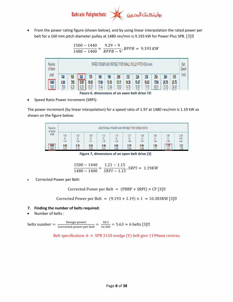
From the power rating figure (shown below), and by using linear interpolation the rated power per
belt for a 160 mm pitch diameter pulley at 1480 rev/min is 9.193 kW for Power Plus SPB. [3]�
1500 − 1440
1480 − 1400=
9.29 − 9
𝐵𝑃𝑃𝐵 − 9, 𝐵𝑃𝑃𝐵 = 9.193 𝐾𝑊
Speed Ratio Power Increment (SRPI):
The power increment (by linear interpolation) for a speed ratio of 1.97 at 1480 rev/min is 1.19 kW as
shown on the figure below:
1500 − 1440
1480 − 1400=
1.21 − 1.15
𝑆𝑅𝑃𝐼 − 1.15, 𝑆𝑅𝑃𝐼 = 1.19𝐾𝑊
Corrected Power per Belt:
Corrected Power per Belt = (PBBP + SRPI) × CF [3]�
Corrected Power per Belt = (9.193 + 1.19) × 1 = 10.383KW [3]�
7. Finding the number of belts required:
Number of belts :
belts number = Design power
Corrected power per belt=
58.5
10.383= 5.63 ≈ 6 belts [3]�
Belt specification: 6 × SPB 3150 wedge (V) belt give 1199mm centres.
Figure 6, dimensions of an open belt drive [3]
Page 9 of 38
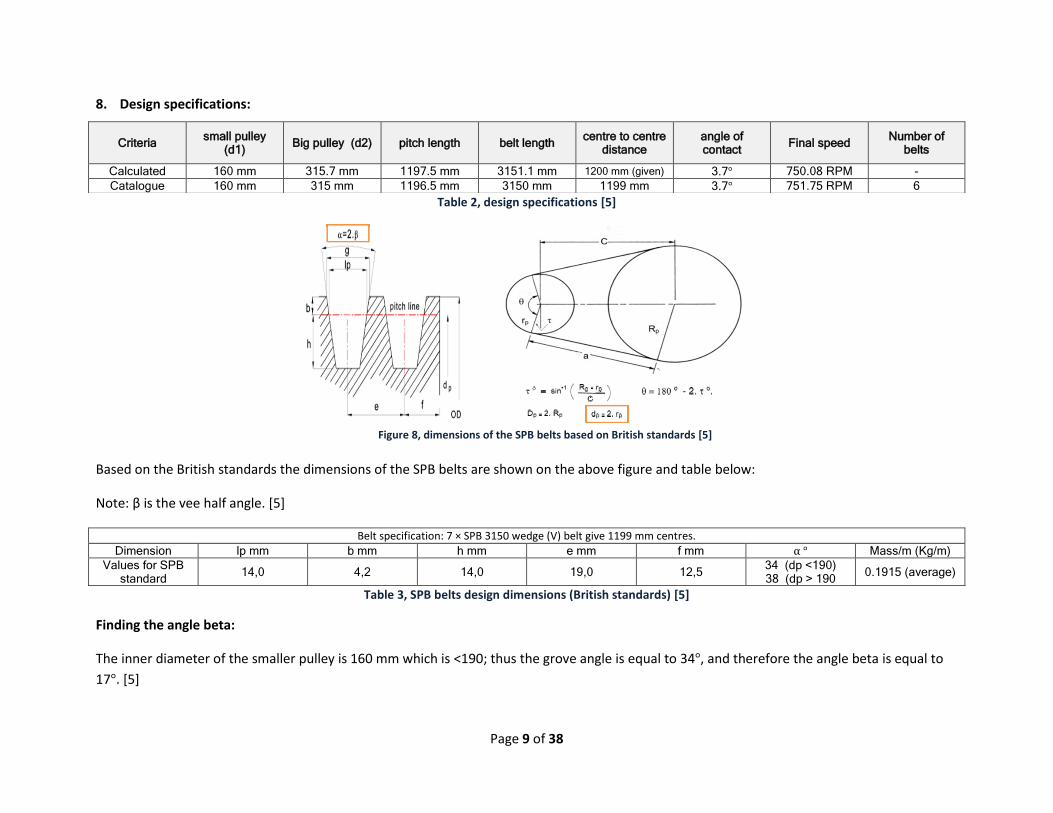
Figure 8, dimensions of the SPB belts based on British standards [5]
8. Design specifications:
Table 2, design specifications [5]
Based on the British standards the dimensions of the SPB belts are shown on the above figure and table below:
Note: β is the vee half angle. [5]
Belt specification: 7 × SPB 3150 wedge (V) belt give 1199 mm centres.
Dimension lp mm b mm h mm e mm f mm α ° Mass/m (Kg/m)
Values for SPB standard
14,0 4,2 14,0 19,0 12,5 34 (dp <190) 38 (dp > 190
0.1915 (average)
Table 3, SPB belts design dimensions (British standards) [5]
Finding the angle beta:
The inner diameter of the smaller pulley is 160 mm which is <190; thus the grove angle is equal to 34°, and therefore the angle beta is equal to
17°. [5]
Criteria small pulley
(d1) Big pulley (d2) pitch length belt length
centre to centre distance
angle of contact
Final speed Number of
belts
Calculated 160 mm 315.7 mm 1197.5 mm 3151.1 mm 1200 mm (given) 3.7° 750.08 RPM -
Catalogue 160 mm 315 mm 1196.5 mm 3150 mm 1199 mm 3.7° 751.75 RPM 6

Page 10 of 38
Figure 9, pulleys, belt, shafts, bearings, motor, bolt design (Isometric)
10, pulleys, V belt, shafts, bearings, motor, pin design (Isometeric)
Figure 11, pulleys, belt, shafts, bearings, motor, bolt design (front side view)
Figure 12, pulleys, belt, shafts, bearings, motor, bolts design (Right side view)
9. Pulleys design:
Note; when the pulley is inside the shaft; the shaft has a pin which makes the pulley rotates with the
shaft. Also there is a thread inside the shaft where the pulley will be fixed through using a bolt as shown
on the figures. The shaft is supported by two cylindrical bearings (in next section I might change the
type). You can see the solid works assembly file for better understanding of the connection method.

Page 11 of 38
Figure 13, Pulley with pin inside (prevent backward and forward mobment), pull tic connected with motor
shaft
Figure 14, Pulley with pin inside (prevent backward and forward mobment), also the shaft is fited by the bearings
Figure 15, shaft supported by a roller bearing (the shown cylinders are for the two bearings)
Figure 16, pulley front side
Figure 18, pulley back side
Figure 17, shaft supported by a roller bearing (the shown cylinders are for the two bearings)
Page 12 of 38
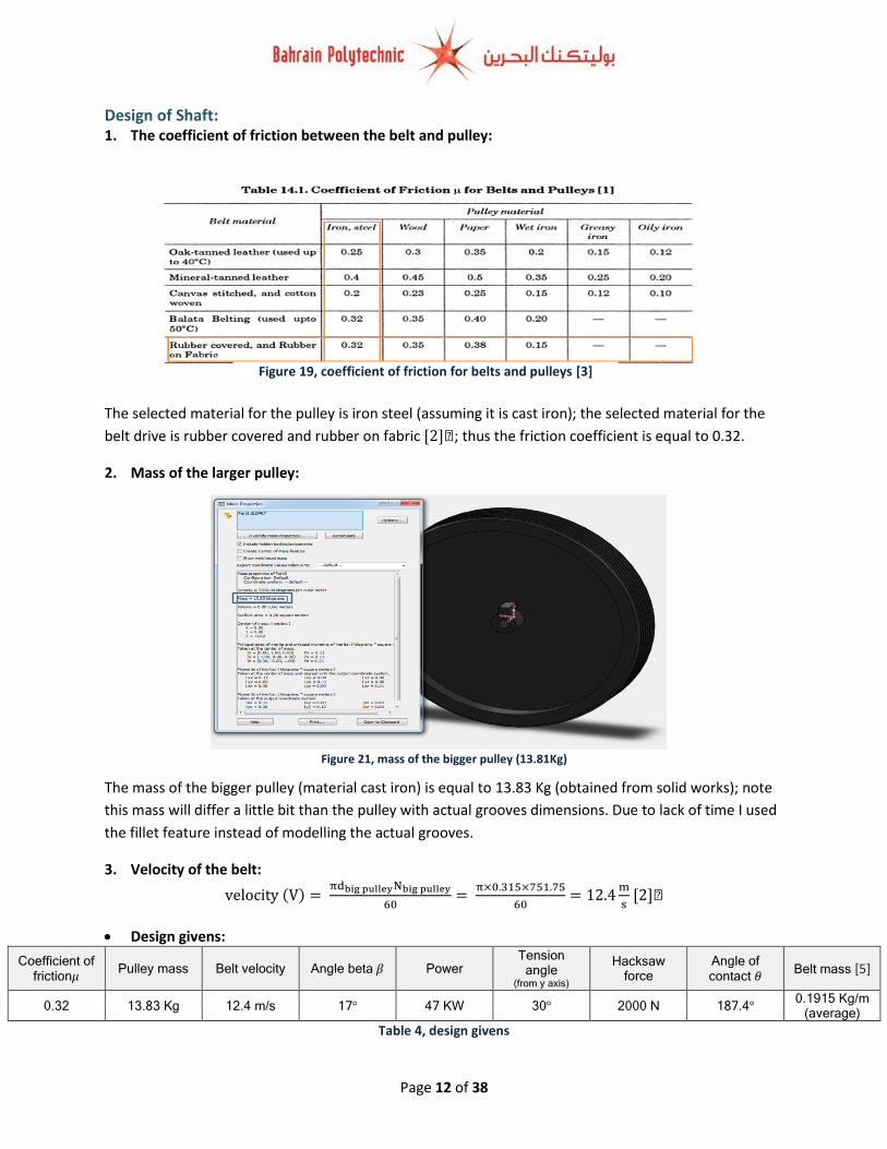
Figure 19, coefficient of friction for belts and pulleys [3]
20, pulleys, V belt, shafts, bearings, motor, pin design (Isometeric)
Design of Shaft: 1. The coefficient of friction between the belt and pulley:
The selected material for the pulley is iron steel (assuming it is cast iron); the selected material for the
belt drive is rubber covered and rubber on fabric [2]�; thus the friction coefficient is equal to 0.32.
2. Mass of the larger pulley:
The mass of the bigger pulley (material cast iron) is equal to 13.83 Kg (obtained from solid works); note
this mass will differ a little bit than the pulley with actual grooves dimensions. Due to lack of time I used
the fillet feature instead of modelling the actual grooves.
3. Velocity of the belt:
velocity (V) = πdbig pulleyNbig pulley
60=
π×0.315×751.75
60= 12.4
m
s [2]�
Design givens:
Coefficient of friction𝜇
Pulley mass Belt velocity Angle beta 𝛽 Power Tension
angle (from y axis)
Hacksaw force
Angle of contact 𝜃
Belt mass [5]
0.32 13.83 Kg 12.4 m/s 17° 47 KW 30° 2000 N 187.4° 0.1915 Kg/m
(average)
Table 4, design givens
Figure 21, mass of the bigger pulley (13.81Kg)
Page 13 of 38
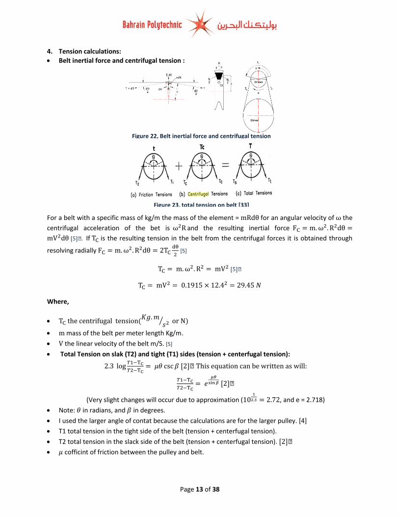
Figure 22, Belt inertial force and centrifugal tension [5]
Figure 23, total tension on belt [33]
4. Tension calculations:
Belt inertial force and centrifugal tension :
For a belt with a specific mass of kg/m the mass of the element = mRdθ for an angular velocity of ω the
centrifugal acceleration of the bet is ω2R and the resulting inertial force FC = m. ω2. R2dθ =
mV2dθ [5]�. If TC is the resulting tension in the belt from the centrifugal forces it is obtained through
resolving radially FC = m. ω2. R2dθ = 2TCdθ
2 [5]
TC = m. ω2. R2 = mV2 [5]�
TC = mV2 = 0.1915 × 12.42 = 29.45 𝑁
Where,
TC the centrifugal tension(𝐾𝑔. 𝑚
𝑠2⁄ or N)
m mass of the belt per meter length Kg/m.
V the linear velocity of the belt m/S. [5]
Total Tension on slak (T2) and tight (T1) sides (tension + centerfugal tension):
2.3 log𝑇1−TC
𝑇2−TC= 𝜇𝜃 csc 𝛽 [2]� This equation can be written as will:
𝑇1−TC
𝑇2−TC= 𝑒
𝜇𝜃
sin 𝛽 [2]�
(Very slight changes will occur due to approximation (101
2.3 = 2.72, and e = 2.718)
Note: 𝜃 in radians, and 𝛽 in degrees.
I used the larger angle of contat because the calculations are for the larger pulley. [4]
T1 total tension in the tight side of the belt (tension + centerfugal tension).
T2 total tension in the slack side of the belt (tension + centerfugal tension). [2]�
𝜇 cofficint of friction between the pulley and belt.

Page 14 of 38
Figure 24, vertical and horizontal components
2.3 log𝑇1 − 29.45
𝑇2 − 29.45=
0.32 × (187.4° ×𝜋
180)
sin 17°= 3.58
2.3 log𝑇1 − 29.45
𝑇2 − 29.45= 3.58
log𝑇1 − 29.45
𝑇2 − 29.45=
3.58
2.3
𝑇1 − 29.45
𝑇2 − 29.45= 10
3.582.3 = 36.01
𝑇1 − 29.45 = 36.01 × (𝑇2 − 29.45)
𝑇1 − 29.45 = 36.01 × 𝑇2 − 1060.789
𝑇1 = 36.01 × 𝑇2 − 1031.0445 → (1)
𝑃 = ((𝑇1 − 29.45) − (𝑇2 − 29.45) × 𝑉
𝑃 = (𝑇1 − 𝑇2) × 𝑉
𝑃 = ((36.01 × 𝑇2 − 1031.0445) − 𝑇2) × 𝑉
47000 = (35.01 × 𝑇2 − 1031.0445 ) × 12.4
𝑇2 = 137.7139983 𝑁
𝑇1 = (36.01 × 137.7139983) − 1031.0445
𝑇1 = 3928.036579 𝑁
Checking: 𝑃 = (𝑇1 − 𝑇2) × 𝑉 = (3928.036579 − 137.7139983) × 12.4 = 47000 𝑊
The total tension force that act on the shaft:
Ttotal = T1 + T2 = 3928.036579 + 137.7139983 = 4065.751 N (The proof is shown in the appendix)
This tension force act on the shaft with an angle of 30 degrees generates vertical and horizontal components as
shown on the FBD below (the angle 30 is a given from the assignment paper):

Page 15 of 38
Figure 26, FBD of the shaft front view (vertical forces)
27, pulleys, V belt, shafts, bearings, motor, pin design (Isometeric)
Figure 28, FBD of the shaft top view (horizontal forces)
29, pulleys, V belt, shafts, bearings, motor, pin design (Isometeric)
Two more forces are acting on the shaft; the first force acts horizontally which is the maximum force
that generated by the hack saw (2000N) which acts toward right side (note this force acts on the second
side of shaft “figure 28” ) , and the pulley mass (13.83 (Kg) × 9.81 = 135.67N) which they act toward
downward as shown below:
In my analysis I assumed that the mass of the belt is negligible, also the torque that generated due
to hack saw tangential force is negligible because I still do not know the diameter of the shaft, and
also it is assumed that this torque is small comparing to the torque due to tension.
The free body diagrams of the forces that act on the shaft are shown below:
Figure 25, forces act on the shaft (hack saw force act on the second end of the shaft)

Page 16 of 38
Summary of force that act on the shaft:
Vertical forces (act downward) Pulley mass 135.67 N @ zero
distance Tension (T cos 30)
4065.751 N cos 30 @ zero distance
Horizontal forces (act rightward) hack saw force 2000N @ 0.475 m
distance Tension (T sin 30)
4065.751 N sin 30 @ zero distance
Table 5, summary of forces
Reaction that act on the shaft figure 26, and 28:
1. Vertical reaction force (pulley mass and the tension vertical component); as shown on figure 26
the total force that act on the left side of the shaft is equal to:
(4065.751 N × cos 30) + 135.67𝑁 = 3656.71 𝑁
Finding the reaction forces (Ra and RB) “figure 26”:
∑MRb = 0, ACW = CW
0.4 × 3656.71 N = Ra × 0.3
Ra = 4875.61 N
∴ RB = 4875.61 − 3656.71 = 1218.9 N (∑FY = 0)
Finding the maximum bending moment:
For the bending diagram: maximum bending moment: shear force times distance
𝑏𝑒𝑛𝑑𝑖𝑛𝑔 𝑚𝑜𝑚𝑒𝑛𝑡 = −3656.71N × 0.1 = −365.671 N. m
2. Horizontal forces; tension horizontal component which acts on the left side of the shaft, and the
hacksaw force which acts on the end side of the shaft:
Hacksaw 2000 N
Tension 4065.751 × sin 30 = 2032.8755 N
Finding the reaction forces (Ra and RB) “figure 28”:
∑MRb = 0, ACW = CW
(0.075 × 2000) + (Ra × 0.3) = (0.4 × 2032.8755)
Ra = 2210.5 N
∴ RB = 2000 + 2032.8755 − 2210.5 = 1822.3755 N (∑FY = 0)
Finding the maximum bending moment:
For the bending diagram: maximum bending moment: shear force times distance = −2032.8755N ×
0.1 = −203.28755 N. m Note: shear forces and bending moment diagrams are shown on page 15 & 16.

Page 17 of 38
Finding equivalent bending moment =
√𝑚𝑎𝑥𝑖𝑚𝑢𝑚 𝑏𝑒𝑛𝑑𝑖𝑛𝑔 𝑚𝑜𝑚𝑒𝑛𝑡 ℎ𝑜𝑟𝑖𝑧𝑜𝑛𝑡𝑎𝑙2 + 𝑚𝑎𝑥𝑖𝑚𝑢𝑚 𝑏𝑒𝑛𝑑𝑖𝑛𝑔 𝑚𝑜𝑚𝑒𝑛𝑡 𝑣𝑒𝑟𝑡𝑖𝑐𝑎𝑙2
√203.287552 + 365.671 2 = 418.379 𝑁. 𝑚
Forces on the reactions (RA), and (RB):
Force Ra (bearing A) Rb (bearing B)
Vertical force 4875.61 N 1218.9 N
Horizontal force 2210.5 N 1822.3755N
Resultant force 5353.31 N 2192.43 N
WResultant = √WV2 + WH
2
Table 6, summary of forces act on the reaction Ra and Rb (bearings)
5. The torque on the shaft:
The tension on belt without considering centrifugal force (from the equation2.3 logT1
T2= μθ csc β)
t1 = 108.2330834 N & t2 = 3898.55564 N
Torqueshaf output = (t2 − t1) × raduis of big pulley [2]
Torqueshaf output = (3898.55564) − (108.2330834) × 0.1575 = 597 N. m
Or (with considering centrifugal force) Torqueshaf output = (T2) − (T1) × raduis of big pulley
Torqueshaf output = (3928.036579 − 137.7139983) × 0.1575 = 597 N. m
OR (from power formula)
Power (P) = 2π × speed(N) × Torque(T)
60 [2]
Torqueshaf output = 60P
2π × Nbig pulley
Torqueshaf output =60 × 47 × 1000
2π × 751.75= 597 N. m
Note the big T means the total tension, t the friction tension, and Tc the centrifugal tension:
Check: 𝑇𝑐 = 𝑇 − 𝑡 = 137.7139983 − 108.2330834 = 29.5 N [2]
Summary of forces on shaft :
Total bending moment 418.379 𝑁. 𝑚
Torque 597 N. m
Table 7, summary of forces act on shaft

Page 18 of 38
6. Shear force and bending moment diagrams: A. Shear force and bending moment diagram for vertical forces:
(Assuming the loads act on the shaft are pointed loads)
Vertical forces (act downward) Pulley mass 135.67 N @ zero distance Tension (T cos30)
4065.751 N cos30 @ zero distance (3521.043 N)
Output shaft - length 0.475m (total load 3656.71 𝑁)
Figure 30, free body diagram, shear force and bending moment diagram (for vertical forces) [31]
N.m
Free body diagram
Shear force diagram
Bending moment diagram
Page 19 of 38
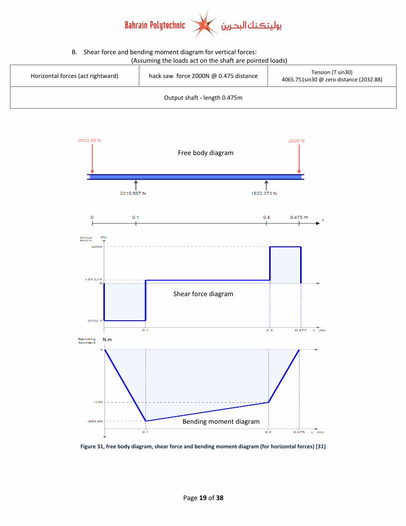
B. Shear force and bending moment diagram for vertical forces: (Assuming the loads act on the shaft are pointed loads)
Horizontal forces (act rightward) hack saw force 2000N @ 0.475 distance Tension (T sin30)
4065.751sin30 @ zero distance (2032.88)
Output shaft - length 0.475m
Figure 31, free body diagram, shear force and bending moment diagram (for horizontal forces) [31]
N.m
Free body diagram
Shear force diagram
Bending moment diagram

Page 20 of 38
7. Equivalent torque:
TEquivalent = √M2 + T2
where: M the maximun bending moment, and T is the torque on the shaft
TEquivalent outpt shaft = √418.379 2 + 5972 = 729 N. m
8. Calculating shaft diameter and shaft material selection
The equivalent torque can be found from torsion formula, and from this formula we can
determine the shaft diameter as shown below:
T
J=
Gθ
l=
τ
r [3]�
T
J=
τ
r
T (torsional moment ) = τ × J
𝑑2
𝐽 (Polar moment of inertia ) =𝜋𝑑4
32
T = τ × (
𝜋𝑑4
32 )
𝑑2
= 𝜋
16× 𝜏𝑚𝑎𝑥 × 𝑑3
𝜋
16× 𝜏𝑚𝑎𝑥 × 𝑑3 = √M2 + T2
𝑑 = √16 × √M2 + T2
𝜋 × 𝜏𝑚𝑎𝑥
3
[3]
One of the materials that is used to manufacture the shaft is ASSAB 705M which is an alloyed machinery steel with good hardenability also in heavier sizes with a tensile yield strength of 690 MPa. [6] Based on [7]; the shear stress (τ) of Wrought Steel and alloy steel is approximately equal to 0.75 of the material yield strength 𝑆𝑢.
τ = Approx 0,75 × Su
τ (ASSAB 705M) = 0,75 × 690 = 517.5 MPa Taking a factor of safety of as 2.1 (just assumption); the maximum allowable shear stress will equal
to: (517.5/2.1 = 246.4285714 MPa)
𝑑𝑜𝑢𝑡𝑝𝑢𝑡 𝑠ℎ𝑎𝑓𝑡 = √16 × 729
𝜋 × 246.4285714 × 106
3
= 0.02469 𝑚 = 24.69 𝑚𝑚 ≈ 25𝑚𝑚

Page 21 of 38
Figure 32, FBD of the shaft (for the resultant force)
33, pulleys, V belt, shafts, bearings, motor, pin design (Isometeric)
Size and selection of bearings: 1. Forces on the bearing: As explained in the shaft section there are four forces are acting on the shaft; two on the y axis (vertical
forces) which they are the pulley mass and the vertical total tension component (with considering the
centrifugal tension), and two on the X axis (horizontal forces) which they are the maximum force
generated by the hacksaw machine and horizontal total tension component (with considering the
centrifugal tension) as shown on the figure 31. When the left end side of the shaft is exposed to a
resultant force R1 from the pulley mass and (vertical and horizontal components of tension); a reaction
(R2) will be created act on the bearing opposite to the direction of (R1); R2 is divided into vertical and
horizontal components. In bearing B a reaction will be created opposite to the vertical component of
bearing A, and horizontal component against the machine force (2000 N), the resultant of the two
components create the reaction R3. These reaction forces are the forces that act on the bearing or the
bearing force that keeps the shaft in its place. The figure below shows the forces that act on each
bearing:
As shown on the figure above; R1 is the resultant force act on the shaft, R2 the resultant reaction force
act on the first bearing (A) and R3 the resultant reaction force act on the second bearing (B). The
symbols h and V are the directions of the vertical and horizontal components of the reactions
respectively. I do not need to recalculate the reaction forces; the table below show the resultant force
that act on each bearing:
Bearing A 5353.31 N
Bearing B 2192.43 N
Table 8, forces act on each bearing
2. Selecting type of bearing: As mentioned in the assignment paper SKF bearings will be used for the two bearings; SKF bearings are rated per 1 million revolutions. A 0.9 reliability of bearings is the rating life of a group of nominally identical ball or roller bearings. It is defined as the number of revolutions that 90 % of a group of bearings will achieve or exceed before the failure criterion occurs. A catalogue load rating is defined as the radial load that causes 10 percent of a group of bearings to fail at the bearing manufacturer’s rating life. We shall denote the catalogue load rating as C10. In short, a 90 % reliably means that the catalogue load rating is C10. [8]
Page 22 of 38
Figure 34, FBD of the shaft (for the resultant force) [8]
35, pulleys, V belt, shafts, bearings, motor, pin design (Isometeric)
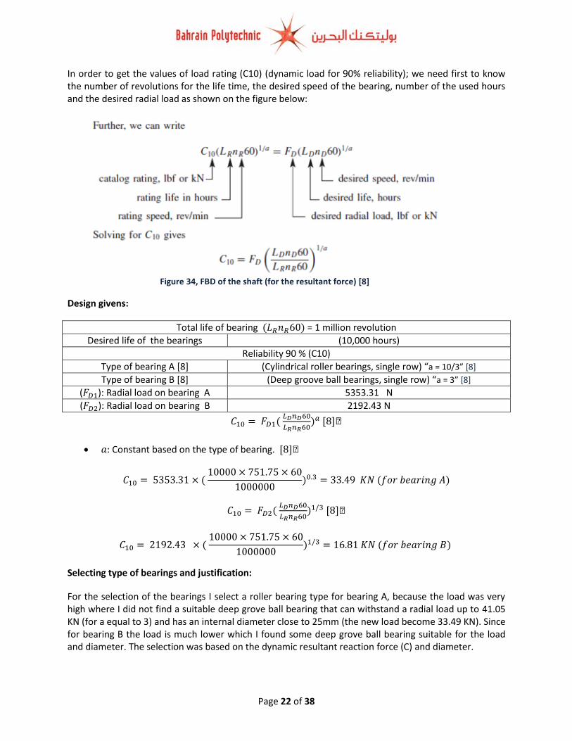
In order to get the values of load rating (C10) (dynamic load for 90% reliability); we need first to know the number of revolutions for the life time, the desired speed of the bearing, number of the used hours and the desired radial load as shown on the figure below:
Design givens:
Total life of bearing (𝐿𝑅𝑛𝑅60) = 1 million revolution
Desired life of the bearings (10,000 hours)
Reliability 90 % (C10)
Type of bearing A [8] (Cylindrical roller bearings, single row) “a = 10/3” [8]
Type of bearing B [8] (Deep groove ball bearings, single row) “a = 3” [8]
(𝐹𝐷1): Radial load on bearing A 5353.31 N
(𝐹𝐷2): Radial load on bearing B 2192.43 N
𝐶10 = 𝐹𝐷1( 𝐿𝐷𝑛𝐷60
𝐿𝑅𝑛𝑅60)𝑎 [8]�
𝑎: Constant based on the type of bearing. [8]�
𝐶10 = 5353.31 × ( 10000 × 751.75 × 60
1000000)0.3 = 33.49 𝐾𝑁 (𝑓𝑜𝑟 𝑏𝑒𝑎𝑟𝑖𝑛𝑔 𝐴)
𝐶10 = 𝐹𝐷2( 𝐿𝐷𝑛𝐷60
𝐿𝑅𝑛𝑅60)1/3 [8]�
𝐶10 = 2192.43 × ( 10000 × 751.75 × 60
1000000)1/3 = 16.81 𝐾𝑁 (𝑓𝑜𝑟 𝑏𝑒𝑎𝑟𝑖𝑛𝑔 𝐵)
Selecting type of bearings and justification:
For the selection of the bearings I select a roller bearing type for bearing A, because the load was very high where I did not find a suitable deep grove ball bearing that can withstand a radial load up to 41.05 KN (for a equal to 3) and has an internal diameter close to 25mm (the new load become 33.49 KN). Since for bearing B the load is much lower which I found some deep grove ball bearing suitable for the load and diameter. The selection was based on the dynamic resultant reaction force (C) and diameter.

Page 23 of 38
Figure 36, Selected bearing for bearing A [10]
37, pulleys, V belt, shafts, bearings, motor, pin design (Isometeric)
Figure 38, Selected bearing for bearing B [11]
39, pulleys, V belt, shafts, bearings, motor, pin design (Isometeric)
For the reliability of the bearing of SKF I did not search about the reliability because “all information presented by SKF with regard to load ratings is based on the life that 90% of a sufficiently large group of apparently identical bearings can be expected to attain or exceed”. [9] The two figures below show the selected bearings:
Type: Cylindrical roller bearings, single row
Actual load (radial) Bearing load Shaft diameter Bearing internal diameter
33.49 KN 34.1 KN 25 mm 25 mm
Model Outside diameter Bearing Width mass
NJ 2205 ECP 52 mm 18 mmm 0.014 Kg Table 9, Selected bearing for bearing A [10]
Deep groove ball bearings, single row
Actual load (radial) Bearing load Shaft diameter Bearing internal diameter
16.81 KN 17.8 KN 25 mm 25 mm
Model Outside diameter Bearing Width Mass
6205-ETN 9 52 mm 15 mmm - Table 10, Selected bearing for bearing B [11]
Note; the ball bearing and roller bearing was selected based on magnitude of radial force, the internal diameter of the bearing and also our application (using bearings to support a horizontal rotating shaft), these two types of bearings are suitable for our desired shaft where they provide the support for normal rotation. Furthermore, these bearing can withstand radial loads (specifically roller bearings are used for heavy radial loads), and also these bearings can work in a high speed.
Page 24 of 38
Figure 40, Ball bearing construction [32]
Research part What the bearing is??
A bearing is a machine component which constrains the relative motion and reduces the friction
among moving parts to only the required motion. The design of the bearing may use for free linear
movement of the moving part or for free rotation around a fixed axis, bearings may be used to prevent
motion through controlling the vectors of normal forces that bear on the moving parts. Numerous
bearings also facilitate the desired motion as much as possible, such as through minimizing friction.
Bearings are categorized based on the type of operation, the motions allowed, or the directions of the
forces that applied to the parts. The bearings are designed to decrease the friction among the moving
parts or to support moving loads. [12]. There are two main kinds of bearings; the first type is called
antifriction for instance, the roller bearing and the ball bearing, operate on the principle of rolling
friction. The second type called the plain, or sliding for example, the journal bearing and the thrust
bearing, employing the principle of sliding friction. Roller bearings are either cylindrical or tapered
(conical), based on their applications application; they overcome frictional resistance by a rolling
contact; they are suited to large, heavy assemblies. Ball bearings are usually found in light precision
machinery where high speeds are required, friction being reduced by the rolling action of the hard steel
balls. In both types the balls or rollers are caged in an angular grooved track, known as a race, and the
bearings are held in place through a frame ball bearing or roller bearings reduce friction more than
sliding bearings do. One advantage of antifriction bearings includes the ability to work at high speeds
and easy in lubrication. The life of rolling element bearing can be determined through load,
temperature, maintenance, lubrication, material defects, contamination, handling, installation and other
factors. [13]
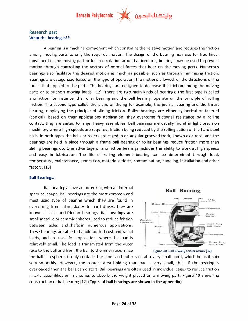
Ball Bearings:
Ball bearings have an outer ring with an internal
spherical shape. Ball bearings are the most common and
most used type of bearing which they are found in
everything from inline skates to hard drives; they are
known as also anti-friction bearings. Ball bearings are
small metallic or ceramic spheres used to reduce friction
between axles and shafts in numerous applications.
These bearings are able to handle both thrust and radial
loads, and are used for applications where the load is
relatively small. The load is transmitted from the outer
race to the ball and from the ball to the inner race. Since
the ball is a sphere, it only contacts the inner and outer race at a very small point, which helps it spin
very smoothly. However, the contact area holding that load is very small, thus, if the bearing is
overloaded then the balls can distort. Ball bearings are often used in individual cages to reduce friction
in axle assemblies or in a series to absorb the weight placed on a moving part. Figure 40 show the
construction of ball bearing [12] (Types of ball bearings are shown in the appendix).

Page 25 of 38
Figure 42, Needle Roller bearing [32]
Figure 41, Straight Roller bearing [32]
Roller Bearings:
Roller bearings contain cylinders instead of spheres; this means that the contact among the
inner and outer race is a line not a point. Therefore, the load is spread over a larger area allowing the
bearing to handle higher loads comparing to ball bearings. Roller bearings are used in conveyer belt
rollers where they hold heavy radial loads, however these bearings are not designed to handle much
thrust loading. [14] (Types of roller bearings are shown in the appendix).
Needle Roller Bearing:
Needle roller bearings are special roller bearings having slender cylindrical rollers that allow
them to bear highest load capacity for a given radial space of all rolling element bearings. Needle roller
bearings are suitable for applications that require high radial load carrying capacity; however, the radial
space is limited. Needle bearings are also suitable for applications that high rotational speed is involved
but cannot accommodate axial loads. Compared to the ball bearings, needle bearing have a large
surface area that is in contact with the bearing outer surfaces. Furthermore, they are more compact due
to there is less difference among the diameter of the shaft and the diameter of the bearing. Needle
bearings are mostly used in engine parts for example pumps, compressors, rocker arm pivots, and
transmissions. [15]
Tapered Roller Bearing:
Tapered roller bearings use conical rollers that run on conical races. Both the inner and outer
raceways are segments of cones and the rollers are also made with a taper. Unlike other roller bearings,
they support both radial and axial loads, and are able to carry higher loads. The conical geometry of
tapered roller bearings offer a larger contact patch, which permits greater loads to be carried as
compared to spherical (ball) bearings. The geometry confirms that the tangential speeds of the surfaces
of each of the rollers are same as their raceways along the whole length of the contact patch and no
differential scrubbing occurs. This greatly reduces rolling friction and avoids rapid wear. Taper roller

Page 26 of 38
Figure 45, Ball thrust bearing [32]
Figure 43, Tapered Roller bearing [32]
bearings are used in the wheel bearings of most trucks, buses, cars, and so on. Due to manufacturing
complexities, tapered roller bearings are generally more expensive than ball bearings. [16]
Spherical Roller Bearings:
Spherical roller bearings consist of an outer ring with an internal spherical shape. The rollers are
thicker in the middle and thinner at the ends. Therefore, spherical roller bearings can accommodate
both static and dynamic misalignment. However, spherical rollers are difficult to produce and therefore
expensive. These bearings have higher friction than an ideal cylindrical or tapered roller bearing.
Spherical bearings are used in many applications where rotational motion changes the alignment of its
axis of rotation. One of its important examples is a tie rod on a vehicle suspension. Other important uses
of spherical bearings have been in car suspensions, trackballs, computer mouse, heavy machinery,
sewing machines, drive shafts, etc. [17]
Thrust Bearings:
Thrust bearings are a particular kind of rotary bearings which
allows rotation among parts used; also, they are designed to support
axial loads like vertical shafts for which spherical, conical or cylindrical
rollers are used. They are used in gear sets like in car transmissions
between gears and between the housing and the rotating
shafts. Thrust bearings are of different varieties. Ball thrust bearings
are composed of ball bearings supported in a ring. They are used in
low thrust applications where the radial load is very small. Thrust roller
bearings are made of small tapered rollers arranged so that their axes
converge at a point on the axis of the bearing. [18]
Figure 44, Spherical Roller [16] Bearings

Page 27 of 38
Figure 46, Drive chain. [20]
Chains (power transmitting chains):
A belt or a rope does not provide a constant velocity ratio as a consequence of possible slipping that
may happens due to overloads or if the belt and pulley surfaces becomes greasy. The ropes or belts can
be replaced by a chain when there is a demand to have a constant velocity ratio or a positive drive. The
chains are made up of a series of links with links held together with steel pins; the chains are regarded in
between the gear drive and the belt drive. The chains are made of metal so they occupy less space, and
give constant velocity ratio. Also the arrangement of chains makes the chains strong, and able to
transmit the rotary motion from one gear wheel to another for long ways (can be used for long center
distances). However, the disadvantages of a chain drive are that it is heavier comparing to belt drives or
ropes, there is a gradual stretching of it and it requires lubrication. The power transmitting chains are used
for transmission of power, when the distance between the centers of shafts is short [19]
Summary of Advantages and disadvantages of chains:
Advantages of chains Disadvantages of chains
Perfect velocity ratio can be obtained due to there is no slip takes place.
The chain drive gives high transmission efficiency (up to 98 %).
The chain drives can be used if the distance between the shafts is less.
They occupy less space in width comparing to a belt or rope drive.
The chain drive can transmit motion to several shafts through one chain only.
The chain drive gives fewer loads on the shafts.
Expensive
Needs accurate mounting and careful maintenance.
Chain drive has velocity fluctuations
Table 11, Advantages and disadvantages of chains [2]�
The wheels over which the chains are run, corresponding to the pulleys of a belt drive is called
sprockets. The surface of sprockets confirm to the type of chain used. Typically, a sprocket has projected
teeth that fit into the recesses in the chain. Therefore, the chain passes round the sprockets as a series
of choral links as shown on the figure below: [19]
Page 28 of 38
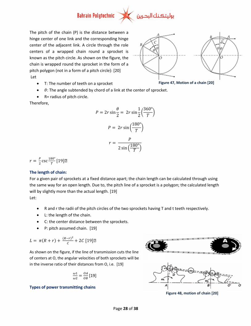
Figure 47, Motion of a chain [20]
Figure 48, motion of chain [20]
The pitch of the chain (P) is the distance between a
hinge center of one link and the corresponding hinge
center of the adjacent link. A circle through the role
centers of a wrapped chain round a sprocket is
known as the pitch circle. As shown on the figure, the
chain is wrapped round the sprocket in the form of a
pitch polygon (not in a form of a pitch circle): [20]
Let
T: The number of teeth on a sprocket
𝜃: The angle subtended by chord of a link at the center of sprocket.
R= radius of pitch circle.
Therefore,
𝑃 = 2𝑟 sin𝜃
2= 2𝑟 sin
1
2(
360°
𝑇)
𝑃 = 2𝑟 sin (180°
𝑇)
𝑟 = 𝑃
2 sin (180°
𝑇)
𝑟 = 𝑃
2csc
180°
𝑇 [19]�
The length of chain:
For a given pair of sprockets at a fixed distance apart; the chain length can be calculated through using
the same way for an open length. Due to, the pitch line of a sprocket is a polygon; the calculated length
will by slightly more than the actual length. [19]
Let:
R and r the radii of the pitch circles of the two sprockets having T and t teeth respectively.
L: the length of the chain.
C: the center distance between the sprockets.
P: pitch assumed chain. [19]
𝐿 = 𝜋(𝑅 + 𝑟) + (𝑅−𝑟)2
𝐶+ 2𝐶 [19]�
As shown on the figure, if the line of transmission cuts the line
of centers at O, the angular velocities of both sprockets will be
in the inverse ratio of their distances from O, i.e. [19]
𝜔1
𝜔2=
𝑂𝐴
𝑂𝐵 [19]
Types of power transmitting chains
Page 29 of 38
Figure 49, the roller chain. [21]
Figure 51, Bush chain [2]
Figure 50, the inverted tooth or silent chain [21]
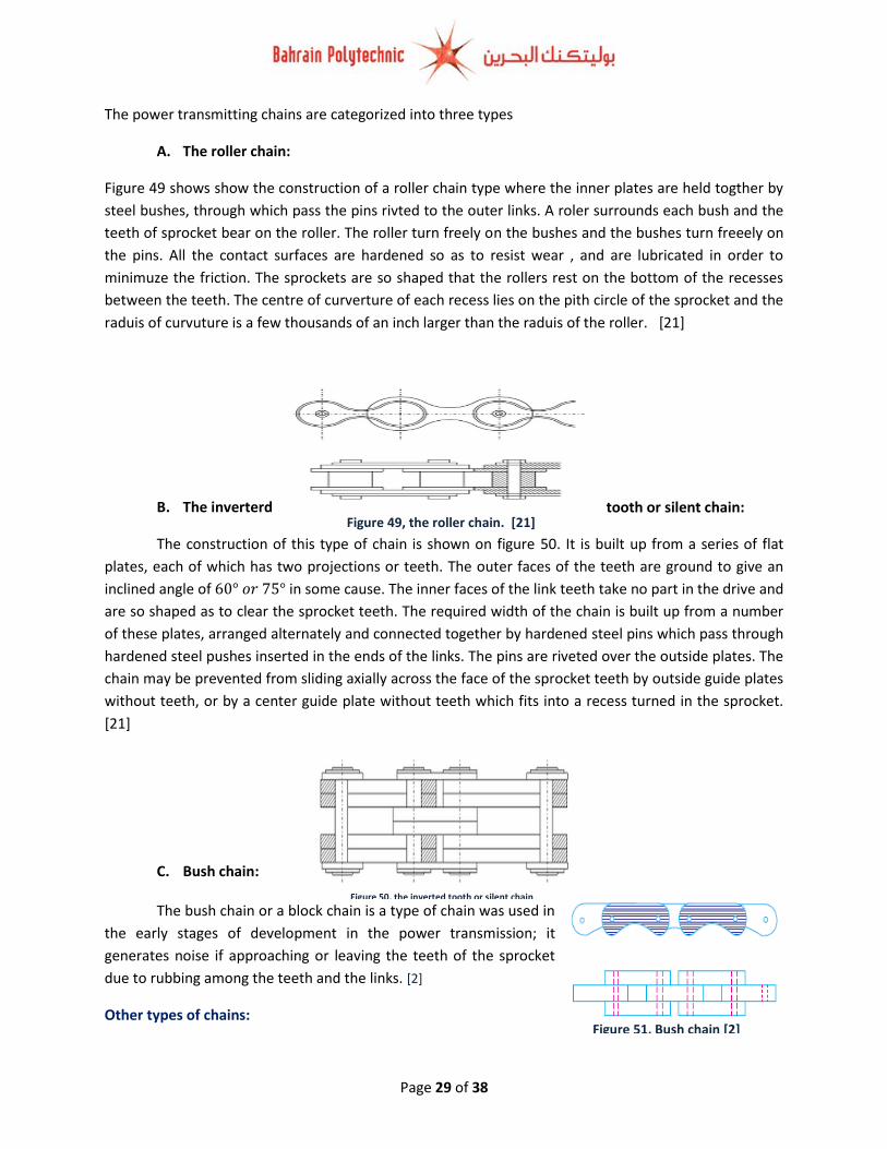
The power transmitting chains are categorized into three types
A. The roller chain:
Figure 49 shows show the construction of a roller chain type where the inner plates are held togther by
steel bushes, through which pass the pins rivted to the outer links. A roler surrounds each bush and the
teeth of sprocket bear on the roller. The roller turn freely on the bushes and the bushes turn freeely on
the pins. All the contact surfaces are hardened so as to resist wear , and are lubricated in order to
minimuze the friction. The sprockets are so shaped that the rollers rest on the bottom of the recesses
between the teeth. The centre of curverture of each recess lies on the pith circle of the sprocket and the
raduis of curvuture is a few thousands of an inch larger than the raduis of the roller. [21]
B. The inverterd tooth or silent chain:
The construction of this type of chain is shown on figure 50. It is built up from a series of flat
plates, each of which has two projections or teeth. The outer faces of the teeth are ground to give an
inclined angle of 60° 𝑜𝑟 75° in some cause. The inner faces of the link teeth take no part in the drive and
are so shaped as to clear the sprocket teeth. The required width of the chain is built up from a number
of these plates, arranged alternately and connected together by hardened steel pins which pass through
hardened steel pushes inserted in the ends of the links. The pins are riveted over the outside plates. The
chain may be prevented from sliding axially across the face of the sprocket teeth by outside guide plates
without teeth, or by a center guide plate without teeth which fits into a recess turned in the sprocket.
[21]
C. Bush chain:
The bush chain or a block chain is a type of chain was used in
the early stages of development in the power transmission; it
generates noise if approaching or leaving the teeth of the sprocket
due to rubbing among the teeth and the links. [2]
Other types of chains:

Page 30 of 38
Figure 52, hoisting and hauling chains [3]
Figure 53, Conveyor chains [3]
1. Hoisting and hauling chains.
This type of chains is used for hoisting and hauling purposes; the hoisting and hauling chains are divided
into two types:
A. Chain with oval links:
As shown on the figure below part “a” the links of this kind of chain are of oval shape. The joint
of each link is welded. The sprockets which are used for this type of chain have receptacles to receive
the links. Such type of chains is used only at low speeds for example in chain hoists and in anchors for
marine works. [3]
B. Chain with square links.
As shown on the figure below part “b” the links of this type of chain are in a square form. Such
type of chains is used in hoists, cranes, dredges. The cost of this type of chain is less expensive
comparing to the chain with oval links, but in these chains, the kinking occurs easily on overloading. [3]
2. Conveyor chains
This type of chains is used for elevating and conveying the materials continuously. The conveyor chains
are typically made of malleable cast iron. These chains do not have smooth running qualities. The
conveyor chains run at slow speeds of about 3 to 12 Kmℎ𝑟⁄ . As shown on the figure below, the
conveyor chains are divided into two types, detachable (hook joint) type chain “a”, and closed joint type
chain “b”:

Page 31 of 38
Figure 54, friction plate clutch [24]
What the clutch is??
A clutch is a machine member used to connect and disconnect the driving and driven shafts of a
machine. Thus, the driven shaft can be either started or stopped at will, without stopping the driving
shaft. So the clutch provides an interruptible connection between two rotating shafts clutches allow a
high inertia load to be stated with a small power. [22]. Clutches are used whenever the transmission of
motion or power need be controlled (either in amount or over time); one popular application of using
clutch is in automotive vehicles. It is used to connect the engine and the gear box; the clutch enables to
crank and start the engine disengaging the transmission disengage the transmission and change the gear
to alter the torque on the wheels. [23]
The clutches typically contain a driving shaft and a driven shaft; they are classified to externally or
internally controlled clutches. The externally controlled clutches can be controlled either by friction
surfaces or components that engage or mesh positively. Since, the internally controlled clutches are
controlled by internal mechanisms or devices; they are further classified as overload, overriding, and
centrifugal. There are many different arrangements for a driving shaft to engage a driven shaft. [23]
Several materials were used in the past for the disc-friction facings including the asbestos. The new
clutches (modern) usually use a compound organic resin with copper wire facing or a ceramic material;
the coefficient of friction used on a friction disc surface is 0.35 for organic, and 0.25 for ceramic. The
ceramic materials are usually used for heavy applications like heavy duty hauling. [24]
1. Externally Controlled Friction Clutches
A. Friction Plate Clutch:
The friction plate clutch transmits power by the friction developed among the mating plate faces.
The left sliding plate is fitted with a control arm, and the right plate member is free to rotate on the
shaft. [25] As shown on the figure below; when the arm is actuated; it advances a sliding plate on the
driving shaft to engage a mating rotating friction plate on the same shaft; this motion engages
associated gearing that drives the driven shaft. When reversed, the control arm disengages the sliding
plate. The clutch torque capacity is based on the axial force that exerted by the control half when it
engages the sliding half. [24]

Page 32 of 38
Figure 55, Cone clutch [24]
Figure 56, Expanding Shoe Clutch [24]
As shown on the above figure; if the left sliding plate on the driving shaft is clamped by the control arm
against the right friction plate idling on the driving shaft; the friction transmits the power of the driving
shaft to the friction plate. The gear teeth on the friction plate will mesh with a gear mounted on the
driven shaft to complete the transfer of power to the driven mechanism.
B. Cone Clutch:
From its name, the cone clutch has conical friction surfaces. It has the same working principle as the
friction plate clutch except that the control arm advances a cone on the driving shaft to engage a mating
rotating friction cone on the same shaft; this motion also engages any associated gearing that drives the
driven shaft. The cone clutch requires axial movement for engagement, however less axial force is
required comparing to plate clutch due to the increased friction between mating cones. The friction
surface can be on either cone but is typically only on the sliding cone. One of the most common
examples of a cone clutch is a synchronizer ring in a manual transmission. The synchronizer ring is
responsible for "synchronizing" the speeds of the shift hub and the gear wheel to ensure a smooth gear
change. [22]
C. Expanding Shoe Clutch:
Expanding shoe clutch is similar to the friction-plate clutch except that the control arm engages
linkage that forces several friction shoes radially outward so they engage the inner surface of a drum on
or geared to the driven shaft. [22]

Page 33 of 38
Figure 57, Jaw Clutch [24]
Figure 58, expanding-shoe centrifugal clutch [24]
2. Externally Controlled Positive Clutches
A. Jaw Clutch:
Jaw Clutch is similar to the plate clutch except that the control arm advances a sliding jaw on the
driving shaft to make positive engagement with a mating jaw on the driven shaft. To clarify, the left
sliding half of this clutch is feathered to the driving shaft while the right half rotates freely. The control
arm activates the sliding half to engage or disengage the drive. The jaw clutch is simple, strong clutch is
subject to high shock during engagement and the sliding half exhibits high inertia. Also, the engagement
requires long axial motion. [25]
B. Other examples:
Two more examples of externally controlled positive clutches are the planetary transmission clutch
which consists of a sun gear keyed to a driveshaft, two planet gears, and an outer driven ring gear. The
second example is pawl and ratchet clutch that basically consist of a pawl-controlled driving ratchet
keyed to a driven gear. [24]
3. Internally Controlled Clutches (they can be controlled by springs, torque, or centrifugal force):
A. The expanding-shoe centrifugal clutch
Centrifugal clutch performs in a similar manner to the externally controlled expanding shoe clutch
except that there is no external control. Two friction shoes, attached to the driving member, are held
inward by springs until reaching the (clutch in) speed. At that speed centrifugal force drives the shoes
outward into contact with the drum. If the drive shaft rotates faster the pressure between the shoes
against the drum will increases; leading to increase the clutch torque. [26]

Page 34 of 38
Figure 59, overriding clutch [24]
B. The overrunning (overriding clutch):
Overriding clutch is a specialized form of a cam mechanism which is known also a cam and roller
clutch. The inner driving cam A has wedge shaped notches on its outer rim that hold rollers between the
outer surface of A and the inner cylindrical surfaces of outer driven ring B. If the driving cam A is turning
clockwise, frictional forces wedge the rollers tightly into the notches to lock outer driven ring B in
position so it also turns in a clockwise direction. Though, if driven ring B is reversed or runs faster
clockwise than driving cam A the rollers are set free, the clutch will slip and no torque will be
transmitted. Some versions of this clutch include springs between the cam faces and the rollers to
ensure faster clutching action if driven ring B tries to drive driving cam A through overcoming residual
friction. A version of this clutch is the basic free wheel mechanism that drives the rear axle of a bicycle.
[26]
As shown on the above figure; as the driving cam A revolves clockwise, the rollers in the wedge-
shaped gaps between cam A and outer ring B are forced by friction into those wedges and are held
there; this locks ring B to cam A and drives it clockwise. But, if ring B is turned counterclockwise, or is
made to revolve clockwise faster than cam A; the rollers are freed by friction, the clutch slips, and no
torque is transmitted. [24]
Page 35 of 38
Works Cited
[1] Dr. Subramanian , "Assignment 4 (motor spped data)," Bahran polytechnic, Manama, 2014.
[2] R.S.Khurmi, Theory of machine, N.I: N.I, n.d..
[3] R.S.Khurmi, Theory of machine, n.d..
[4] Engineers Ediges , "V belt," engineersedge, 2000-2015. [Online]. Available:
http://www.engineersedge.com/belt_design/belt_design_1.htm. [Accessed 2 1 2015].
[5] roymech, "Vee belts V belts," roymech, 22 1 2013. [Online]. Available:
http://www.roymech.co.uk/Useful_Tables/Drive/Vee_belts.html. [Accessed 1 1 2015].
[6] "ASSAB 705M," 2014. [Online]. Available:
http://www.matweb.com/search/DataSheet.aspx?MatGUID=b0f23fe4fbb844f5a3e71cfa0e31f513&ckck=1.
[7] "shear tensile," n.d.. [Online]. Available:
http://www.roymech.co.uk/Useful_Tables/Matter/shear_tensile.htm).
[8] Shigley’s , Mechanical Engineering Design, New York (ISBN 978-0-07-352928-8): McGraw-Hill, 2011.
[9] SSKF, "Bearing life and load ratings," SKF, 2015. [Online]. Available:
http://www.skf.com/group/products/bearings-units-housings/ball-bearings/principles/selecting-bearing-
size/bearing-life/index.html. [Accessed 4 1 2015].
[10] "Cylindrical roller bearings, single row," SKF, 2015. [Online]. Available:
http://www.skf.com/group/products/bearings-units-housings/roller-bearings/cylindrical-roller-
bearings/single-row-cylindrical-roller-bearings/single-row/index.html?prodid=1500412205&imperial=false.
[Accessed 4 1 2015].
[11] skf, "Deep groove ball bearings, single row," skf, skf. [Online]. Available:
http://www.skf.com/group/products/bearings-units-housings/ball-bearings/deep-groove-ball-
bearings/single-row-deep-groove-ball-bearings/single-row/index.html?prodid=1010100205&imperial=false.
[Accessed 4 1 2015].
[12] "bearing," science.howstuffworks, 2014. [Online]. Available:
http://science.howstuffworks.com/transport/engines-equipment/bearing3.htm.
[13] "Ball bearing," wikipedia, 2014. [Online]. Available: http://en.wikipedia.org/wiki/Ball_bearing.
[14] "bearing," riv, n.d.. [Online]. Available: http://www.riv.org/bearing.htm.
[15] "catalog," ntn, 2012. [Online]. Available: http://www.ntn.co.jp/english/products/catalog/pdf/2202E_a01.pdf.

Page 36 of 38
[16] SKF, "spherical roller bearings," skf, 2014. [Online]. Available: http://www.skf.com/group/products/bearings-
units-housings/roller-bearings/spherical-roller-bearings/cylindrical-and-tapered-
bore/index.html?prodid=1550502208&imperial=false. [Accessed 6 1 2015].
[17] "Principle anball and roller bearings," cedengineering, 2011. [Online]. Available:
https://www.cedengineering.com/upload/Principles%20and%20Use%20of%20Ball%20and%20Roller%20Bea
rings.pdf.
[18] "types of bearings," hardwaremarketplace, n.d.. [Online]. Available:
http://www.hardwaremarketplace.com/information-guide/types-of-bearings.html.
[19] Rattan, Theory of Machines, Tata McGraw-Hill , 2005.
[20] V. Ryan, "GEAR WHEELS (SPROCKETS) AND CHAINS," technologystudent, 2004. [Online]. Available:
http://www.technologystudent.com/gears1/chain1.htm.
[21] B. V. R. Gupta, Theory of Machines: Kinematics and Dynamics, I. K. International Pvt , 2010.
[22] "Machine Design," nptel, n.d.. [Online]. Available: http://nptel.ac.in/courses/IIT-
MADRAS/Machine_Design_II/pdf/3_5.pdf.
[23] "Clutch," wikipedia, 2014. [Online]. Available: http://en.wikipedia.org/wiki/Clutch.
[24] N. SCLATER, MECHANISMS AND MECHANICAL DEVICES SOURCEBOOK, NewYork: McGraw-Hill, 2011.
[25] "clutches with external control," mechanicaldatahelp, n.d.. [Online]. Available:
https://mechanicaldatahelp.wordpress.com/2011/10/08/clutches-with-external-control/.
[26] Basic Mechanical Engineering.
[27] G. M. Maitra, Handbook of Gear Design, 2008.
[28] "Unit 4 and 5: MECHANICAL DRIVES," in MECHANICAL DRIVES, n.d..
[29] Spur-gear geometry factors, n.d..
[31] "bendingmomentdiagram," 2015. [Online]. Available: http://bendingmomentdiagram.com/free-calculator/.
[Accessed 2 1 2015].
[32] stle, "An Engineering Guide for Bearing Selection," stle, FEBRUARY 2004. [Online]. Available:
https://www.stle.org/assets/document/Engineering_Guide_for_Bearing_Selection.pdf. [Accessed 5 1 2015].
[33] N. Prakashan, Theory of Machines and Mechanisms - II, Pune: H.G.phakatkar, 2008.
Page 37 of 38
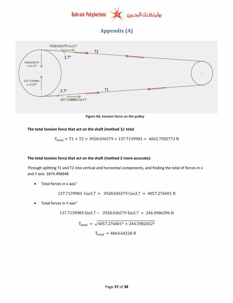
Figure 60, tension force on the pulley
61, pulleys, V belt, shafts, bearings, motor, pin design (Isometeric)
Appendix (A)
The total tension force that act on the shaft (method 1): total
Ttotal = T1 + T2 = 3928.036579 + 137.7139983 = 4065.7505773 N
The total tension force that act on the shaft (method 2 more accurate):
Through splitting T1 and T2 into vertical and horizontal components, and finding the total of forces in x
and Y axis: 1874.496648
Total forces in x axis”
137.7139983 Cos3.7 + 3928.036579 Cos3.7 = 4057.276001 N
Total forces in Y axis”
137.7139983 Sin3.7 − 3928.036579 Sin3.7 = 246.4986396 N
Ttotal = √4057.2760012 + 244.59826522
Ttotal = 4064.64228 𝑁
T2
T1
Page 38 of 38
Appendix (B)
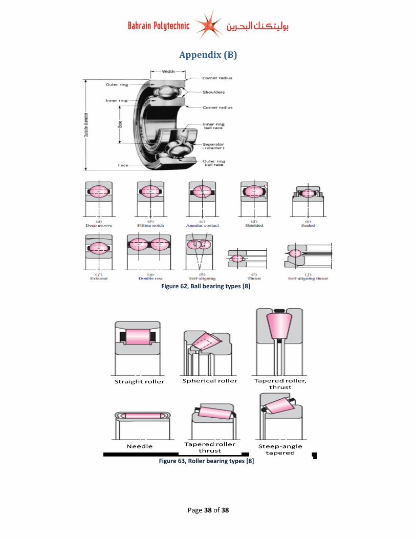
Figure 62, Ball bearing types [8]
Figure 63, Roller bearing types [8]