power system stabilization of a grid highly penetrated
TRANSCRIPT
EasyChair Preprint№ 5718
Power System Stabilization of a Grid HighlyPenetrated from a Variable-Speed Wind BasedFarm Through Robust Means of STATCOM andSSSC
Pierre Dorile, Daniel Jagessar, Lizbeth Guardado, Sarah Jagessarand Roy McCann
EasyChair preprints are intended for rapiddissemination of research results and areintegrated with the rest of EasyChair.
June 4, 2021

Power System Stabilization of a Grid HighlyPenetrated from a Variable-Speed Wind Based Farm
Through Robust Means of STATCOM and SSSCPierre O. Dorile, Daniel R. Jagessar, Lizbeth Guardado, Sarah S. Jagessar, Roy A. McCann
Department of Electrical EngineeringUniversity of Arkansas
Fayetteville, AR 72701, [email protected], [email protected]
Abstract—There has been significant strides to integrate renew-able energy sources into our current power system. In this work,we focus on wind farm integration into a weak grid. To ensurethat this proposed idea is suitable, we perform tests to ensure thatthe power system remains stable under some potential scenarios.To facilitate integration and suitable steady state conditions aremaintained, the use of Flexible AC Transmission System (FACTS)devices are employed. In this work, we focus on the transientstability characteristic for power system stability. Specifically,we present how the use of Static Synchronous Compensators(STATCOM) in the first portion of this work, used alongsideStatic Synchronous Series Compensators (SSSC) to improvevoltage stability, also improved transient stability of the winddominated power system.
Index Terms—power system stability, transient stability, windgeneration, High-Inverter Based Resource Penetration, Compen-sation devices
I. INTRODUCTION
The electric power system is one of the most importantinfrastructure to the world today [1]. As time continues, thedemand on the grid increases in an attempt to supply theneeds of power provision. However, there are many challengesseen by system engineers. Any power system must maintain aspecific level of performance on top of meeting load demands.Thus, in expanding, there is also the concern on impacts inthis regard. It is also imperative to note that power systems arelarge, highly non linear systems which also have varying timecharacteristics [2]. As a result, there are various influencesand responses that any power engineer must study to trulyconclude a power system is reliable.
For most power systems, there exists synchronized devicesfor generating power and receiving that spans over largegeographical areas and are connected with other networks toform one mesh that exchanges power. Power systems with highpower output transmitting over long distance are those thatsuffer from more stability problems. Large disturbances andsmall disturbances limit transmission capability which evenposes a stronger threat as distance increase. The power flowof many systems can reach over thousand of Megawatts ofpower [3]. Each device in the power system is intertwined
with each other to form the network. However, as alreadymentioned, each device provides its own dynamic which arenon-linear in nature. Thus, affecting the performance of thesystem as a whole. Even though components of the systemare never in isolation, the stability as a result of the non-linear characteristics can mostly be studied through isolation[1,2,3]. That is, at various parts of equilibrium. This shows,that planning is a very tedious process in power systemgeneration, distribution and transmission. Per IEEE guidelines[4], power system stability refers to the ability of an electricalpower system to return to its equilibrium operation stateafter being under a physical disturbance withing its givenoperating conditions and system variable bounds. Furthermore,the entire system should remain intact and services should notbe interrupted.
However, with the increasing emission of green housegases, there becomes an increasing demand to reduce theaforementioned. As such, renewable sources such as windenergy has become more developed recently worldwide. Theproblem that arises is that these components provides its ownunique dynamics, and, thus, its own challenges. As such, weneed to employ compensating devices which can stabilize,prevent voltage collapses and mitigate/alleviate faults in acertain area of power system (or node) that consists of windturbines, thus preventing the issue propagating throughoutthe entire network. There has been extensive studies whichsuggests various means to enhance grid resiliency, maintaincode compliance, and compensate reactive power in the sys-tem. The STATCOM has been suggested to provide the bestmeans to enhance the dynamic stability in a wind dominatedsystem which is then displayed on the transient stability andoverall stabilization of the power system. In this work, theSTATCOM will be operating as a voltage source converter(VSC) device that can then support the grid through theprovision of reactive power into it. This paper therefore studiesthe impact of the STATCOM and SSSC in its response tounforeseen circumstances on a DFIG based wind farm and isa continuation of [5].

II. STATCOM APPLICATIONS
The STATCOM is one of the most sophisticated powerelectronics-based member of the family devices called FACTS.Static Synchronous Compensator is a power electronic-baseddevice that uses forced commutated devices like IGBT, GTOfor reactive power flow control in a transmission grid. Theycan either assist in absorbing or generating reactive power intoa transmission grid to ameliorate the voltage stability [6,7].
A. Working principles of STATCOM
The working principle of STATCOM, is shown throughthe transfer equation of reactive power. To show, two voltagesources, V1 and V2, are considered and is connected togetherthrough an impedance Z = R+ jX .
Fig. 1. Two voltage sources connected via an impedance
For a transmission line, the resistance can be neglected incomparison to the reactance of the line. The reactive powerflow of the reactive power is:
Q =V2X
(V1 cos δ − V2) (1)
δ is the angle between V1 and V2. if δ = 0 we have{Q = V2
X (V1 − V2)P = V1V2
X sin δ(2)
It is evident that if δ = 0, there is a zero flow of activepower and the reactive power flow becomes a function of thedifference between the two sources indicated as follows, V1−V2 For reactive power flow, there are two cases.
1) if V1 > V2 , reactive power will flow from V1 to V22) if V1 < V2, reactive power will flow from V2 to V1The STATCOM uses this principle to control reactive
power flow through the transmission line. FACTS devices arewidely used to ameliorate the dynamics and transient stabilityof a wind-dominated power system.
The STATCOM has the following components as outlinedin [8].
1) To convert a DC input to AC, a Voltage Source Converter(VSC) is employed. There are two types: square waveinverters and pulse width modulation (PWM) inverters.
2) To provide a constant DC voltage to the VSC, we use aDC capacitor.
3) Between the VSC and the transmission grid, inductivereactance, from the transformer, is inserted.
4) The harmonics alongside other high-frequency resultantsfrom the VSC is filtered through harmonic filtering.
Fig. 2. Electrical diagram of STATCOM [8]
The STATCOM can operate in two modes namely:1) Voltage regulation mode2) Var control modeThe following figure shows the two-mode of operations of
the STATCOM
Fig. 3. Operation modes of a STATCOM
It can be seen that the voltage regulation of the STATCOMis between V1and V2 if the transmission grid voltage is lowerthan V1 or higher than V2. In this case, the STATCOM operatesin Var control mode.
B. Motivations for STATCOM
Voltage stability is a major concern for power systemoperations. Engineers and researchers are busy trying to findthe best techniques to mitigate this phenomenon. Now-a-day,the power system is being increasingly stressed due to thegreater demand for electrical energy. It is burdensome toacquire new Right of Way of transmission lines. Huge demandon the transmission grid and absence of long-term planninghas caused resulted in less security, thus reducing the powerquality of supply. To alleviate this problem, reactive powercompensation is essential. It is well established, that seriesand shunt compensation can increase the maximum transfer
capabilities of the transmission line. Compensation aims tokeep the voltage magnitude at the buses close to nominalvalues by injecting reactive power.
The output power of the wind farm and the total demandload demand fluctuates constantly. STATCOM is installed tokeep the voltage magnitudes in the permissible ranges. TheSTATCOM can participate in the Low Voltage Ride Troughrequirements since it can operate at full capacity and extremelylow voltage. In this work, a VSC PWM technique is used toimprove the voltage stability of the wind farm.
C. STATCOM Modeling
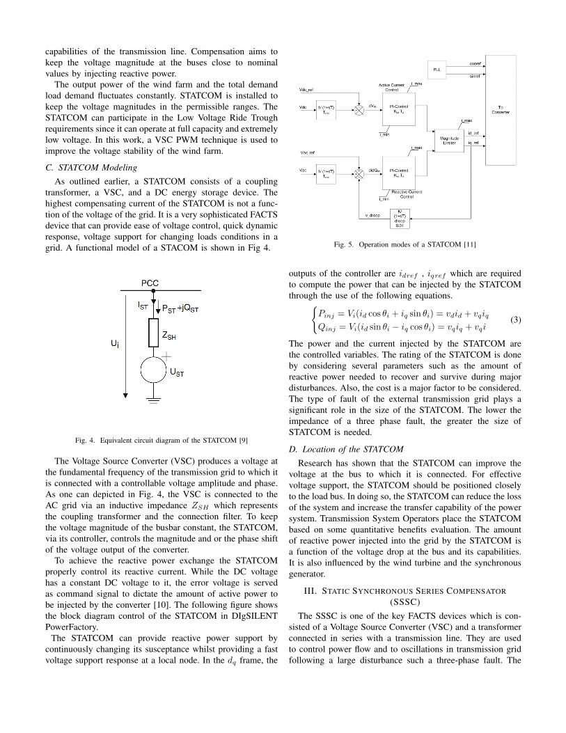
As outlined earlier, a STATCOM consists of a couplingtransformer, a VSC, and a DC energy storage device. Thehighest compensating current of the STATCOM is not a func-tion of the voltage of the grid. It is a very sophisticated FACTSdevice that can provide ease of voltage control, quick dynamicresponse, voltage support for changing loads conditions in agrid. A functional model of a STACOM is shown in Fig 4.
Fig. 4. Equivalent circuit diagram of the STATCOM [9]
The Voltage Source Converter (VSC) produces a voltage atthe fundamental frequency of the transmission grid to which itis connected with a controllable voltage amplitude and phase.As one can depicted in Fig. 4, the VSC is connected to theAC grid via an inductive impedance ZSH which representsthe coupling transformer and the connection filter. To keepthe voltage magnitude of the busbar constant, the STATCOM,via its controller, controls the magnitude and or the phase shiftof the voltage output of the converter.
To achieve the reactive power exchange the STATCOMproperly control its reactive current. While the DC voltagehas a constant DC voltage to it, the error voltage is servedas command signal to dictate the amount of active power tobe injected by the converter [10]. The following figure showsthe block diagram control of the STATCOM in DIgSILENTPowerFactory.
The STATCOM can provide reactive power support bycontinuously changing its susceptance whilst providing a fastvoltage support response at a local node. In the dq frame, the
Fig. 5. Operation modes of a STATCOM [11]
outputs of the controller are idref , iqref which are requiredto compute the power that can be injected by the STATCOMthrough the use of the following equations.{
Pinj = Vi(id cos θi + iq sin θi) = vdid + vqiq
Qinj = Vi(id sin θi − iq cos θi) = vqiq + vqi(3)
The power and the current injected by the STATCOM arethe controlled variables. The rating of the STATCOM is doneby considering several parameters such as the amount ofreactive power needed to recover and survive during majordisturbances. Also, the cost is a major factor to be considered.The type of fault of the external transmission grid plays asignificant role in the size of the STATCOM. The lower theimpedance of a three phase fault, the greater the size ofSTATCOM is needed.
D. Location of the STATCOM
Research has shown that the STATCOM can improve thevoltage at the bus to which it is connected. For effectivevoltage support, the STATCOM should be positioned closelyto the load bus. In doing so, the STATCOM can reduce the lossof the system and increase the transfer capability of the powersystem. Transmission System Operators place the STATCOMbased on some quantitative benefits evaluation. The amountof reactive power injected into the grid by the STATCOM isa function of the voltage drop at the bus and its capabilities.It is also influenced by the wind turbine and the synchronousgenerator.
III. STATIC SYNCHRONOUS SERIES COMPENSATOR(SSSC)
The SSSC is one of the key FACTS devices which is con-sisted of a Voltage Source Converter (VSC) and a transformerconnected in series with a transmission line. They are usedto control power flow and to oscillations in transmission gridfollowing a large disturbance such a three-phase fault. The

SSSC can inject a voltage of variable magnitude in quadraturewith the line current. As a result, they can easily emulate aninductive or capacitive reactance. This emulated reactance caninfluence the power flow in the transmission line.
Fig. 6. Block diagram of a SSSC [12]
A. Sizing of the SSSC
The SSSC, as a reactive power, can inject compensationvoltage in quadrature the line current. The voltage can eitherbe positive or negative and the SSSC rating can computed asfollow:
SSSCRating = (√3)(IMax)(VSSSCMax) (4)
In this work, the optimal rating capacity of the SSSC is notcomputed. So, the SSSC might be oversized in the testingwhich deals with simulation to keep the injected voltage 10percent of the voltage nominal of the power system. The testbed system is the modified IEEE-14 bus system. The use ofseries and shunt FACTS devices is the most sophisticated meanused by electric utilities to improve the voltage stability ofthe system. Stellar works done by scholars and researchers inthe realm of power system engineering have led to the useof FACTS controllers for voltage stability amelioration andoperating flexibility. As one of the key FACTS controllers,the SSSC can improve the dynamic performance of the powersystem and mitigate the damping power oscillation of thepower system after being subjected to a three-phase fault. Athree–phase fault is applied in the middle of the line 1 to 2 toshow the amelioration of the steady-state voltage stability ofa wind-dominated power system using SSSC.
IV. DOUBLY - FED INDUCTION GENERATOR (DFIG)WIND TURBINE DYNAMICS
The DFIG topology uses a wound rotor induction machinewhere the stator is connected to the grid and the rotor is
connected to the grid via a back-to-back power electronicsconverter. The rated capacity of this power converter is be-tween 30% − 50% of the nominal capacity Wind TurbineGenerator. Through the state, reactive power can be providedto the grid.
Fig. 7. Schematic diagram of the DFIG based Wind Turbine [13]
In the d-q reference frame, the stator and rotor of the DFIGcan be expressed as the following equations [13],
vsdq = Rsisdq + jωsλsdq +d
dtλsdq (5)
vrdq = Rrirdq + jωslipλrdq +d
dtλrdq (6)
λs = Lsis + Lmir (7)
λr = Lmis + Lrir (8)
Furthermore, the torque, real and reactive power are repre-sented as follows,
Te =3
2p (ψqsids − ψdsiqs) (9)
Ps = vdsids + vqsiqs (10)
Qs = vdsiqs − vqsids (11)
Tmech − Te = Jd
dtψr +Bψr (12)
V. TEST SYSTEM
Using the IEEE 14 Bus Test System, a DFIG based windfarm was placed instead at Bus 14. A SSSC with rating of150 MVA was inserted between lines 1 and 2 where thevoltage is variable in terms of magnitude and is in quadraturewith the line current. The voltage varies from −0.20p.u. to0.042p.u. by an imitation of a capacitive and reactive reactancerespectively as follows. To begin, the voltage Vref = 0p.uat t = 2s. Then after, Vref = −0.2p.u and at t = 6sVref = 0.042p.u The second step was to place a STATCOMrated at 150 MVA at Bus 2 in Var control mode. In capacitivemode, the STATCOM supplies reactive power to the systemand absorbs reactive power in inductive mode. In the beginningIref = 0 at t = 2s and STATCOM set Iref = −1p.u in

capacitive mode. After t = 6s, Iref = −1p.u inductive modeto control the compensation of the STATCOM controller. Fig.8 provides the modified IEEE 14 Bus Test System.
Fig. 8. Modified IEEE 14 bus system simulation diagram with SSSC &STATCOM
A three-phase fault was applied at different busbars of thetest system and the effect of the SSSC and the STATCOMis appreciated. Table 1 provides the critical clearing time ofseveral buses amid the performance of the system at Bus 14.Following this, to appreciate the effect of the STATCOM amida short-circuit at the PCC, a three-phase fault was applied atBus 14, the weakest bus. Most grid code worldwide considersthe aforementioned fault as part of their FRT. The fault isapplied at t = 1 sec and cleared at t = 1.083 sec. The system isstudied with and without STATCOM. Furthermore, the voltageat bus 14 during the fault, the voltage recovery time, andthe settling time are analyzed and compared. The results aredepicted in Figs. 9 - 11. After the fault has been cleared,the active power oscillates for a long period before reachingits steady-state value.The same scenario is also valid for thereactive as one can see in Fig. 12.
VI. RESULTS AND DISCUSSION
TABLE ICRITICAL CLEARING TIME (CCT)
Faulted Bus No FACTS With STATCOM With SSSCBus 2 0.378 s 0.427 s 0.456 sBus 4 0.425 s 0.489 s 0.539 sBus 6 0.695 s 0.749 s 0.778 sBus 8 0.787 s 0.845 s 0.788 s
Fig. 9. Voltage at the point of interconnection without STATCOM
Fig. 10. Voltage at the point of interconnection with STATCOM
Fig. 11. Wind Farm active power output at PCC without STATCOM
From Fig 8, with the STATCOM the wind farm exhibits abetter performance in the presence of a three-phase fault atthe PCC.
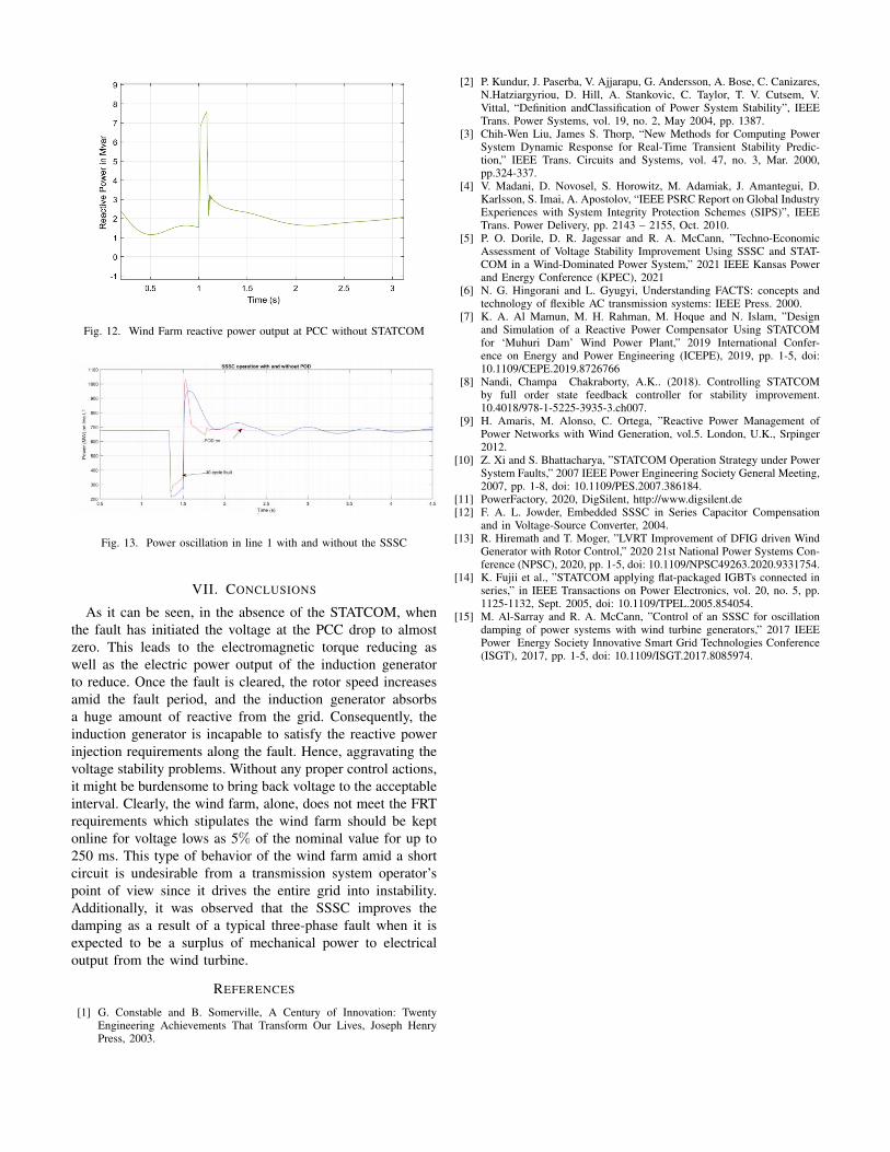
Fig. 12. Wind Farm reactive power output at PCC without STATCOM
Fig. 13. Power oscillation in line 1 with and without the SSSC
VII. CONCLUSIONS
As it can be seen, in the absence of the STATCOM, whenthe fault has initiated the voltage at the PCC drop to almostzero. This leads to the electromagnetic torque reducing aswell as the electric power output of the induction generatorto reduce. Once the fault is cleared, the rotor speed increasesamid the fault period, and the induction generator absorbsa huge amount of reactive from the grid. Consequently, theinduction generator is incapable to satisfy the reactive powerinjection requirements along the fault. Hence, aggravating thevoltage stability problems. Without any proper control actions,it might be burdensome to bring back voltage to the acceptableinterval. Clearly, the wind farm, alone, does not meet the FRTrequirements which stipulates the wind farm should be keptonline for voltage lows as 5% of the nominal value for up to250 ms. This type of behavior of the wind farm amid a shortcircuit is undesirable from a transmission system operator’spoint of view since it drives the entire grid into instability.Additionally, it was observed that the SSSC improves thedamping as a result of a typical three-phase fault when it isexpected to be a surplus of mechanical power to electricaloutput from the wind turbine.
REFERENCES
[1] G. Constable and B. Somerville, A Century of Innovation: TwentyEngineering Achievements That Transform Our Lives, Joseph HenryPress, 2003.
[2] P. Kundur, J. Paserba, V. Ajjarapu, G. Andersson, A. Bose, C. Canizares,N.Hatziargyriou, D. Hill, A. Stankovic, C. Taylor, T. V. Cutsem, V.Vittal, “Definition andClassification of Power System Stability”, IEEETrans. Power Systems, vol. 19, no. 2, May 2004, pp. 1387.
[3] Chih-Wen Liu, James S. Thorp, “New Methods for Computing PowerSystem Dynamic Response for Real-Time Transient Stability Predic-tion,” IEEE Trans. Circuits and Systems, vol. 47, no. 3, Mar. 2000,pp.324-337.
[4] V. Madani, D. Novosel, S. Horowitz, M. Adamiak, J. Amantegui, D.Karlsson, S. Imai, A. Apostolov, “IEEE PSRC Report on Global IndustryExperiences with System Integrity Protection Schemes (SIPS)”, IEEETrans. Power Delivery, pp. 2143 – 2155, Oct. 2010.
[5] P. O. Dorile, D. R. Jagessar and R. A. McCann, ”Techno-EconomicAssessment of Voltage Stability Improvement Using SSSC and STAT-COM in a Wind-Dominated Power System,” 2021 IEEE Kansas Powerand Energy Conference (KPEC), 2021
[6] N. G. Hingorani and L. Gyugyi, Understanding FACTS: concepts andtechnology of flexible AC transmission systems: IEEE Press. 2000.
[7] K. A. Al Mamun, M. H. Rahman, M. Hoque and N. Islam, ”Designand Simulation of a Reactive Power Compensator Using STATCOMfor ‘Muhuri Dam’ Wind Power Plant,” 2019 International Confer-ence on Energy and Power Engineering (ICEPE), 2019, pp. 1-5, doi:10.1109/CEPE.2019.8726766
[8] Nandi, Champa Chakraborty, A.K.. (2018). Controlling STATCOMby full order state feedback controller for stability improvement.10.4018/978-1-5225-3935-3.ch007.
[9] H. Amaris, M. Alonso, C. Ortega, ”Reactive Power Management ofPower Networks with Wind Generation, vol.5. London, U.K., Srpinger2012.
[10] Z. Xi and S. Bhattacharya, ”STATCOM Operation Strategy under PowerSystem Faults,” 2007 IEEE Power Engineering Society General Meeting,2007, pp. 1-8, doi: 10.1109/PES.2007.386184.
[11] PowerFactory, 2020, DigSilent, http://www.digsilent.de[12] F. A. L. Jowder, Embedded SSSC in Series Capacitor Compensation
and in Voltage-Source Converter, 2004.[13] R. Hiremath and T. Moger, ”LVRT Improvement of DFIG driven Wind
Generator with Rotor Control,” 2020 21st National Power Systems Con-ference (NPSC), 2020, pp. 1-5, doi: 10.1109/NPSC49263.2020.9331754.
[14] K. Fujii et al., ”STATCOM applying flat-packaged IGBTs connected inseries,” in IEEE Transactions on Power Electronics, vol. 20, no. 5, pp.1125-1132, Sept. 2005, doi: 10.1109/TPEL.2005.854054.
[15] M. Al-Sarray and R. A. McCann, ”Control of an SSSC for oscillationdamping of power systems with wind turbine generators,” 2017 IEEEPower Energy Society Innovative Smart Grid Technologies Conference(ISGT), 2017, pp. 1-5, doi: 10.1109/ISGT.2017.8085974.