power system protection - eep - electrical engineering portal · 2019-05-12 · power system...
TRANSCRIPT

Power System Protection
1
POWER SYSTEM PROTECTION
LECTURE NOTE
BY
Dr R.K.Jena
Power System Protection
2
Disclaimer
This document does not claim any originality and cannot be used as a
substitute for prescribed textbooks. The information presented here
is merely a collection by the committee faculty members for their
respective teaching assignments as an additional tool for the
teaching-learning process. Various sources as mentioned at the
reference of the document as well as freely available material from
internet were consulted for preparing this document. The ownership
of the information lies with the respective authors or institutions.
Further, this document is not intended to be used for commercial
purpose and the committee faculty members are not accountable for
any issues, legal or otherwise, arising out of use of this document. The
committee faculty members make no representations or warranties
with respect to the accuracy or completeness of the contents of this
document and specifically disclaim any implied warranties of
merchantability or fitness for a particular purpose.

Power System Protection
3
CHAPTER – 1
1.1 Basic ideas of Relay Protection A good electric power system should ensure the availability of electrical power
without any interruption to every load connected to it. Generally power is transmitted through
high voltage transmission line and lines are exposed, there may be chances of their
breakdown due to storms, falling of external objects, and damage to the insulators etc. These
can result not only mechanical damage but also in an electrical fault.
Protective relays and relaying systems detect abnormal conditions like faults in
electrical circuits and automatically operate the switchgear to isolate faulty equipment from
the system as quick as possible.
This limits the damage at the fault location and prevents the effects of the fault
spreading into the system. The switch gear must be capable of interrupting both normal
currents as well as fault current. The protective relay on the other hand must be able to
recognize an abnormal condition in the power system and take suitable steps so that there will
be least possible disturbance to normal operation.
Relay does not prevent the appearance of faults. It can take action only after the fault
has occurred. However, there are some devices which can anticipate and prevent major faults.
For example, Buchholz relay is capable of detecting the gas accumulation produced by an
incipient fault in a transformer.
1.2 Nature and causes of faults
The nature of fault simply implies any abnormal condition which causes a reduction
in the basic insulation strength between phase conductors, between phase conductor and earth
or any earth screen surrounding the conductors.
The reduction of the insulation is not considered as a fault until it produces some
effect on the system i.e. until it results either in an excess current or in the reduction of the
impedance between the conductors, between the conductor and earth to a value below the
lowest load impedance normal to the circuit.
Power systems mainly consist of generator, switch gear, transformer and distribution system.
The probability of failure is more on the power system due to their greater length and
exposure to atmosphere.
(a) Breakdown at normal voltage may occur on account of:
i) The deterioration of insulation
(ii) Damage due to unpredictable causes such as perching of birds, accidental short-
circuiting by snakes, tree branches, etc.
(b) Breakdown may occur because of abnormal voltages: This may happen because of (i)
switching surges (ii) surges caused by lightning

Power System Protection
4
The present practice is to provide a high insulation level of the order 3 to 5 times the normal
voltage, but still:
(i) The pollution on an insulator string caused by deposited soot or cement dust in industrial
area.
(ii) Salt deposited wind borne see spray in coastal area.
These will initially lower the insulation resistances and causes a small leakage current to be
diverted, thus hastening the deterioration.
Secondly, even if the insulation is enclosed, such as sheathed and armoured, the deterioration
of the insulation occurs because of:
(a) Ageing
(b) Void formation in the insulation compound of underground cable due to unequal
expansion and contractions caused by the rise and fall of temperature.
Thirdly, insulation may be subjected to transient over voltages because of switching
operation.
The voltage which rises at a rapid rate may achieve a peak value which approaches
three times phase to neutral voltages.
Lightning produces very high voltage surges in the power system in the order of
million volts. These surges travel with the velocity of light in the power circuit. The
limiting factors are the surge impedance and the line resistance.
1.3 Consequences of Faults
Serious results of the uncleared fault, is fire which may not only destroy the equipment of
its origin but also may spread in the system and cause total failure.
Consequences;
1. A great reduction of the line voltages.
2. Damage caused to the element of the system by the electrical arc.
3. Damage to other parts due to overheating.
4. Disturbanceto the stability of the electrical system and this may even lead to a
complete shutdown of the power system.
5. Reduction in the voltage may fail the pressure coil of the relay.
6. Considerable reduction in the voltage on healthy feeder connected to the system
having fault. This may cause either an abnormally high current being drawn by the motor
or the operation of no volt coils of the motors. (Considerable loss of industrial production
as the motors will have to be restarted).

Power System Protection
5
1.4 Fault Statistics
Equipments % of total faults
O H line 50
Cables 10
Switchgear 15
Transformer 12
CTs & PTs 2
Control Equipment 3
Miscellaneous 8
L-L-L fault are called symmetrical 3-φ fault generally due to carelessness operating
personnel. Usually the three phase lines are tied up together a bare conductor in order to
protect the lineman working on the line against inadvertent-charging of the line. After work is
over, if the linesman forgets to remove the tie-up and CB is closed, a symmetrical fault
occurs.
Line to ground fault occurs most commonly in overhead line. A large no of these faults
are transitory in nature and may vanish within a few cycles (if twig falls across a line and
cross arm and burns itself out or just falls down).
1.5 Essential Qualities of Protection
Every protective system which isolates a faulty element must satisfy four basic
requirements:1. Reliability 2. Selectivity 3. Fastness of operation 4. Discrimination
Reliability
Reliability is a qualitative term. It can be expressed as a probability of failure.
Quality of personnel i.e. mistakes by personnel are most likely causes of failure.
high contact pressure
dust free enclosures
Records show that the order of likelihood of failure is relays, breakers, wiring, current
transformers, voltage transformers and battery.
When relays using transistors are considered, the failure rate goes up still further.
Selectivity :The property by which only the faulty element of the system is isolated and the
remaining healthy sections are left intact.
Selectivity is absolute if the protection responds only to faults within its own zone and
relative if it is obtained by grading the setting of protections of several zones which may

Power System Protection
6
respond to a given fault. The systems of protection which in principle are absolutely selective
are known as unit system. The systems which selectivity is relative are non unit system.
Fastness of Operation
Protective relays are required to be quick acting due to the following reasons:
(a) Critical clearing time should not be exceeded.
(b) Electrical apparatus may be damaged, if they are made to carry fault currents for a
long time.
(c) A persistent fault will lower the voltage resulting in crawling and overloading of
industrial drives.
The figure below shows the typical values of power, which can be transmitted as a function
of time. On the other hand, relays should not be extremely fast; otherwise the relay will
operate for transient conditions.
Discrimination
Protection must be sufficiently sensitive to operate reliably under minimum fault
condition for a fault within its own zone while remaining stable under maximum
load i.e. a relay should be able to distinguish between a fault and an overload.
In the case of transformers, the inrush of magnetising current may be comparable
to the full current, being 5 to 7 times the full load current. The relay should not
operate for inrush current.
In interconnected systems, there will be power swing, which should also be
ignored by the relay.
The word discrimination is sometimes used to include selectivity.
1.6 Primaries and Backup Protection
The relay operates usually from current and voltage derived from current and
potential transformers. A station battery usually provides the circuit breaker trip current.
Successful clearing depends on the condition of the battery, continuity of the wiring and trip
coil and the proper mechanical and electrical operation of the circuit breaker, as well as the
closing of the relay trip contact.
If there is failure of these elements, so that the fault in a given zone is not cleared by the main
or primary protection scheme, some of the backup protection is generally provided.
The backup protection is normally different from main protection and preferably of non-unit
type.
Ex: overcurrent or distance protection
Selectivity is absolute if the protection responds only to faults within its own zone and
relative if it is obtained by grading the settings of protection of several zones which may
respond to a given fault.
Systems of protection which in principle are absolutely selective are known as unit system.

Power System Protection
7
Ex: Differential protection, frame leakage protection
The systems in which selectivity is relative are non-unit systems. Ex: current time graded
protection, distance protection.
1.7 Basic Principle of Operation of Protective relay
Each relay in a protection scheme performs a certain function and responds in a given
manner to a certain type of change in the circuit quantities.
Example:
One type of relay may operate when the current increases above a certain magnitude
known as over current relay
While another may compare current & voltage and operate when the ratio V/I is less
than a given value. It is known as under-impedance relay
Similarly various combinations of these electrical quantities could be worked out according
to the requirementsat a particular situation.
1.8 Economic Considerations
The cost of protection is linked with cost of the plant to be protected and increases
with cost of the plant. Usually, the protective gear should not cost more than 5% of the total
cost. However, when the apparatus to be protected is of paramount importance like the
generator or the main transmission line, the economic consideration are subordinated.
Average Costs in units per circuit ;
Indoor
33 kV
132 kV 275 kV 400 kV
Total Avg. ckt
cost
10 50.0 100 230
Relay 0.7 2.5 2.4 4.6
Relay Panel 0.4 0.6 1.5 2.3
Wiring 0.9 2.0 0.8 0.9
Relay Room 0.32 0.5 0.5 1.0
CTs 0.4 4.7 12.0 25.7
PTs 1.0 3.4 7.0 9.0
References
1. B Ravindranath& M Chander, “Power system Protection and switchgear”New age
International Publishers
2. Y.G Paithankar & S.R Bhide, “Fundamentals of powersystem Protection”PHI
Publication

Power System Protection
8
CHAPTER- 2
Basic Principles and Components of Protection
There must be able to discriminate the appropriate disconnecting device. The method of
discriminating the faults are two types.
(a) Those which discriminate as to the location of fault.
(b) Type of fault
Methods discriminate the type of faults are:
The main aim is that the fault section of the system be isolated and in the minimum time.
a) Discrimination by time
b) Discrimination by current magnitude
c) Discrimination by time and direction
d) Discrimination by distance measurement
e) Time as an addition to current magnitude or distance discrimination
f) current balance discrimination
g) Power direction comparison discrimination
h) Phase comparison discrimination
(a) Discrimination by time:
By adding time lag features to the controlling relay a number of CBs it is possible to trip the
CB nearest to fault in prior to those which are farther from the part of fault.
Let in a radial feeder as shown, the circuit breakers at ABCD are identical and are set operate
for a given value of current. For a fault at any section CD, if the fault current exceeds the set
value the breakers at A,B and C will trip and whole feeder beyond A becomes dead.
For providing time lag to the circuit breakers at ABCD the tripping is delayed in the
following manner.
D- no added time lag
C- .4 sec added time lag
B- .8 sec added time lag
A- 1.2 sec added time lag
Now if the fault occurs in the section CD the breaker at C will trip after a time of .4s and will
clear the fault as a result feeder up to c will remain aline.
A .4s step time is necessary to account for the operation CB and its relay operation time.
(b) Discrimination by current magnitude (Also known as current gradded scheme)

Power System Protection
9
This depends on the current magnitude. As the fault current will also very with location of
fault.If the relays are set to pick up at a progressively higher current towards the source then a
simple feeder system of above fig. can be protected.
(c) Discrimination by time and direction:
Non-directional relays : with same current setting but different time lag. Here proper
discrimination cannot be obtained. Directional relays: with same current setting and different time lag. Fault occurring on any
section will be discriminating cleared without loss of supply.
(d) Discrimination by distance measurement:
Measurement of distance achived in various way known as distance relay
(e) Time as an addition to current magnitude or distance discrimination:
1. time + current grading gives the most practical protection schemes
2. time + distance discrimination forms another practical protection scheme
(f) Current balance discrimination:
Another form of discrimination which is limited in its scope to one system element
which will cause isolation of this element only in the event of fault in this element and will
not respond to any other fault external to this element, even through fault current passes
through it.
Such a protection is known as unit protection.
This form of protection is based on one of the following 2 principles.
1. Circulating current principle
2. Opposed voltage principle or balanced voltage principle.
Circulating current principle
For an external fault the balanced current flow and there will be no current in the relay. So
the apparatus will not be isolated.

Power System Protection
10
Balanced voltage protection
The relay time polarity of CTs at the two ends is such that there is no pilot current for the
condition of load or external fault. For internal fault, the CTs voltage will no longer be
balanced and current will be flow in the relay will trip.
(g) Power direction comparison discrimination:
i) Power flow out at both end
ii) Power flow in at both end.
iii)No power flow either in or out at the other end.
Methods of discrimination to type of fault:
When fault currents may not be very high or may differ little in magnitude from loud
currents as result the current magnitude detection fails to point out such a fault. Such a fault
current has some peculiarity which distinguish itself from the normal load currents.
Ex- in a 3-ph system the currents and voltages can be resolved in to their phase sequence
components which would ultimately give some idea about the nature of the current or
voltages presents.
(a )Zero phase sequence networks:
Zero phase sequence networks
Relay will be energized only by zero sequence current. This relay will ignore load currents
or phase to phase short circuits.
(b) Negative-phase sequence networks:
Negative phase sequence current represents some form of unbalanced condition such as
Phase to phase faults other than symmetrical three phase faults.
Broken conductors

Power System Protection
11
Negative-phase sequence networks
Derivation of a single phase quantity from a three phase quantities:
Auxiliary or pilot wires are used to transmit information from one end of the line to
the other end of the line. For normal 3ph system three pilot would ordinarily be required
which would obviously be a very costly affair for longer system, particularly in transmission
circuit.
It would naturally be preferable to have a mean of deriving a single phase quantities which
under both normal and abnormal conditions will be representative of the three phase
conditions.
Sometimes, it becomes necessary to the sequence current or voltages from correspond line
currents or voltages in order to simplify the protection scheme by reducing the no of relay
required.
There are two commonly used methods for deriving single phase quantities from a three
phase system.
a. summation transformers
b. sequence transformers
(a) Summation transformers:
Summation transformers
Each CT energized a different number of turns as the primary with a resulting single phase
output from the secondary. The output is seen to be proportional to the vector sum.
(n+2)IR + (n+1)IY + n IB
It is also possible to control independently the outputs for earth fault and phase faults.
The output on the earth faults is usually considerably more than that on phase faults is usually
considerably more than that on phase faults so as to provide more sensitive action on earth
faults.
Pick up setting can be expressed in term of combination of n and 1 for the various faults.

Power System Protection
12
Zero output or a negligible small output may occur under through fault condition
when there is a phase to phase fault on the star side of the delta/star transformer giving 1:2:1
current distribution on the protected feeder
(b) Sequence network:
In some cases it is desirable to make the protection respond to a particular phase
sequence component of the three phase system of currents and voltages.
Zero sequence and negative phase sequence networks are frequently used in power system
protection.
Zero sequence networks
Zero sequence networks are extensively used for earth fault protection. During the normal
operation and for three phase and phase to phase faults the current passing through the relay
is zero. When a single or double earth fault occurs, the zero sequence current flow through
the relay.
For unbalanced condition or unsymmetrical faults:
Negative phase sequence network
Negative phase sequence network are used. The values of r and c are there to give a
phase sift of 60 degrees. It can be seen from the phasar diagram that for the +ve sequence
currents the output voltage(Va+Vb) is zero where as for the negative sequence currents the
output voltage is of considerable magnitude to operate the relay.
The protection responding to positive phase sequence components alone is not in
relaying practice. Because under unsymmetrical faults, such a protection will have less
sensitivity due to the fact that the positive phase is only a part of the fault current.

Power System Protection
13
Positive sequence current Negative sequence current
It is possible to use a combination of the positive sequence, negative sequence and
zero sequence networks as a general rule. A combination of positive and negative sequence
networks is wore common.
Components of Protection
Some of the commonly used components of the protective schemes are described here
in brief. Those are
1. Relays
2. CB
3. Tripping and Auxiliary Supplies
4. CTs
5. Voltage Transformers
Relays
When any abnormal condition develop, the main function of a protective relay is to
isolate the faulty section with the least interruption to the service by controlling or operation
the circuit breaker.
The relay may be designed to detect and to measure abnormal condition and close the
contacts of the tripping circuit.
The two categories of relay are most commonly used in protective relay
a) Secondary indirect acting relays
Example: Current, Voltage, Power, Impedance, Reactance and frequency
whether minimum or maximum
b) Secondary directing acting relay
A group of over current and under voltage relays designed to operate
immediately or with time lag.
These are relays of the electromagnetic type which are built into circuit breaker
operating mechanism.
Circuit Breakers

Power System Protection
14
It is desirable to switch on or off the various circuits like transmission line,
distributors generating plants under both normal and abnormal condition.
This can be done by a switch and a fuse but the limitations are
1. It take some time to replace
2. It cannot successfully interrupt heavy fault current.
So we use CB.
It can make or break a circuit either manually or automatically under all conditions (no load,
full load and fault) i.e.
a) It can make or break a circuit manually or by remote under normal condition
b) Break a circuit automatically under fault condition
c) Make a circuit either manually or by remote under fault condition
For operation of CB a relay is necessary. A protective relay is a device that detects the
faults and initiate the operation of the circuit breaker to isolate the defective element from the
rest of the system.
The electrical quantities which may change under fault condition are voltage, current,
frequency and phase angle. Any changes in these quantities indicate presence of the fault.
Tripping and other Auxiliary Supplies
For protective relay and automatic control scheme in power system use two kinds of
auxiliary supplies: DC and AC
DC auxiliary power supply is provided from batteries which is maintained
continuously charged. The advantages of storage batteries are their high reliability and
independent of power circuit conditions and of existence of fault.
Usually the voltage of the auxiliary supplies is maintained at 110 V
Mainly the auxiliary supplies power to protective relays, automatic control and the
circuit breakers tripping circuit.Separate buses may also be provided for supplying power to
relays, CB and other indicating circuit such as alarm and warning signals.
Relay with ac operative power from current transformer
In this scheme the relay has normally closed contacts. During normal operation the
relay contacts continuously shut the circuit breakers trip coil and this keep the breaker closed.
When abnormal condition are approached the relays operates to open its contacts this
put the trip.
Current Transformer (CT)

Power System Protection
15
High magnitude primary current are reduce to a value suitable for relay operation to a
value suitable for relay operation with the help of current transformers (CTs). (Then CTs
provide current in the relay which are proportional to those in primary.)
The primary winding of the CTs is connected in series whit the load and carries the
actual power system current (normal or fault). The secondary is connected to the measuring
circuit or the relay.
The working range of a protective CT extends over the full range between the ankle
and the knee points and beyond. Whereas the measuring CT usually operate in region of
ankle point. Why?
Measuring CTs require comparatively high accuracy over the range of 10% to 120%
of rated.
Grain oriented steels having high saturation level are used As core materials for
protective CTs and nickel iron alloys having low exciting ampere turn per unit length of the
core use4d for measuring CTs.
It is common practice to use 1A secondary rating CTs.
The secondary of the bus bar primary CT is usually about 1500 secondary turn.
When rated primary currents much in excess of 1500 A are encountered then the main
bar CTs with rated secondary current of 5A and 10A along with auxiliary CTs of 5/1 or 10/1
respectively are used.
Voltage Transformers
It is not possible to connect the voltage coils of the protective device directly to the
system in case of high voltage systems. So it is necessary to step down the voltage, also to
insulate the protective equipment from primary circuit. This is achieved by using a voltage
transformers. Also known as potential transformer (PTs) which is similar to a power
transformer. The voltage transformer is rated in terms of the maximum burden (VA) output it
delivers without exceeding specified limits of errors. Whereas the power transformer is rated
by the secondary output it delivers without exceeding a specified temperature rise.
The output of PTs is usually limited to a few hundred volt amperes and the secondary
voltage is usually 110V between phases. Ideally a VT should produce a secondary voltage
exactly proportion al to the primary voltage and exactly in phase opposition. This cannot

Power System Protection
16
obviously be achieved in practice owing to the voltage drops in the primary and secondary
coil due to the magnitude and power factor of the secondary burden. Thus ratio errors and
phase angle errors are introduced.
There are two types of Voltage devices
a) The conventional wound type voltage transformers up to (132kV)
b) Capacitor Voltage Transformer (>132 kV)
When Appreciable current flows in the burden both ratio and phase are introduced
because of the load current flowing through the capacitor C1.
The voltage drop on load due to reluctance of the capacitors can be compensated by
inserting an inductance reactance in series with the load.
Linear Coupler
An iron core CT has limitation of saturation. Also owing to dc offset transient
component present in the fault current, the stability on heavy through faults may be difficult
to obtain.
With air cored CTs, also known as linear coupler, the problem of saturation and dc
offset transient are overcome.
Two major difficulties with relay transient problem are
a) Differential saturation
b) Transference of DC through the iron cored CT
The secondary voltage is given by
It can be seen that the dc component voltage has been attenuated by a ratio R/X which may
be 1/10 to 1/20 depending on the system.
References
3. B Ravindranath& M Chander, “Power system Protection and switchgear”New age
International Publishers
4. Y.G Paithankar & S.R Bhide, “Fundamentals of powersystem Protection”PHI
Publication
Power System Protection
17
Chapter-3
Operating principles and constructional features of relay
3.1 Relay classification
The actuating quantity is normally in electrical signal. Sometimes the actuating quantity may
be pressure and temp.
Protective relay can be classified as
According to the function in protection scheme.
According to the nature of actuating quantity.
According to the connection of the sensing element
According to the method by which the relay acts upon the circuit breaker
Generally the electrical protective relays can be broadly classified in two categories
(a) Electromagnetic relays
(b) Static relays
A relay in which the measurement or comparison of electrical quantities are done in a static
network. The output signal operates a tripping device which may be electronic ,
semiconductor or electromagnetic.
The static relays are classified according to the types of measuring units or the comparator
1) Electronic relays
2) Transducer(magnetic amplifier relay)
3) Rectifier bridge relay
4) Transistor relay
5) Hall effect relay
6) Gauss effect relay
3.2 Principal types of electromagnetic relays
There are two types of electromagnetic relays
a) Attracted armature type
b) Induction type
Attracted armature type
This includes plunger, hinged armature, balanced beam and moving iron polarised
relay. These are simplified types which respond to A.C as well as D.C.

Power System Protection
18
Plunger type) Hinged armature type
Balanced beam type Polarized moving iron type
In dc the electromagnetic force exerted on the moving element is proportional to the square
of the flux or square of the current. In dc electromagnetic relay this force is constant. If this
force exceeds the restraining force, the relay operates.
In ac electromagnetic relays the electromagnetic force is given by
Fe = kI2
= k(Imaxsinwt)2
= ½k Imax 2(1 – coswt )
= ½k( Imax2 – Imax
2cos 2wt )
This indicates that the electromagnetic force consists of two components (i) One
constant(independent of time) and (ii)Another dependent on time and pulsating at double the
frequency of the applied alternating quantities.
The total electromagnetic force pulsates at double the freq. the force is plotted graphically
which shows that Fe =0 in every half period.

Power System Protection
19
If Fr is produced with the help of a spring then it is constant.
Then the relay armature will be picked up at t1 and the armature drops off at t2.
Hence the armature vibrates at double the frequency. This causes the relay to hum and
produces noise and also is a source of damage to relay contacts. This leads to sparking and
unreliable operation of the relay operating circuit contacts due to make and break of the
circuits.
To overcome this difficulties in ac electromagnetic relay the flux that produce
electromagnetic force is divided into two fluxes among simultaneously but differing in time
phase. So that the resultant electromagnetic force is always positive and this is always
greater the restraining force so that the armature will not vibrate. This is achieved through
shaded pole or by providing two windings having a phase shift.
The flux through the shaded pole lags behind the unshaded pole. In case of balanced beam
type two quantities A and B are compared.Actually|A|2 and |B|
2 are compared because the
electromagnetic forces are proportional to (ampere turns)2.It has low ratio of reset by
operating current.
Sensitivity of hinged armature relays can be increased for dc operation by the
addition of a permanent magnet. This is known as a polarised moving iron relay.
Induction type relay
An induction relay essentially consists of aluminium disc placed in two alternating
magnetic flux of same frequency but displaced in time and space.The torque is produced in
the disc by the interactions of one of the magnetic field with the currents induced in the disc
by the other. Induction relays are widely used for protective relaying involving AC
quantities.High, low and adjustable speeds are possible and the various shapes of
time/operating curve can be obtained.
Types of structure
a) Shaded pole

Power System Protection
20
b) Wattmeter or double pole winding structure
c) Induction cup structure
(a) Shaded pole
It consists of
1. 1. Pivoted aluminium disc free to rotate
in the air gap of an electro magnet.
2. 2. One half is surrounded by copper
band known as shaded ring.
The alternating flux in the shaded
portion of the poles will lag behind the
flux in the unshaded portion by an
angle α due to the reaction of the
current induced in the ring.
These two a.c fluxes differing in phase will produce the necessary torque to rotate the disc.
(b )Wattmeter structure or double winding structure
Wattmeter structure
In the wattmeter type these are two magnetic systems. A phase displacement between the
fluxes is obtained either by having different inductance and resistance for the two circuits or
energizing these from two different sources whose outputs are relatively displaced in phase
as shown.
(c )Induction cup structure
The rotating field is produced by two pairs of coils wound on four poles.The rotating field
induced current in the cup to provide the necessary driving torque.

Power System Protection
21
If Φ1 and Φ2 represent the fluxes produced by the respective pair of poles, then the torque
produced is proportional to Φ1. Φ2 sinα i.e
T α Φ1.Φ2 sinα
A control spring and the back stop is provided for closing of the contacts that are attached to
the spindle of the cup to prevent the continuous rotation.
Induction cup structure is more efficient torque producers than shaded pole and wattmeter
type. So this type of relay has very high speed. The operating time is less than 1 second.
3.3 Theory of induction relay torque
Two magnetic fluxes Φ1 and Φ2 differing in time phase penetrate through a disc.
These alternating fluxes induce e.m.f.s e1 and e2 in the disc which lag their respective fluxes
by 90 degrees.
So i1 α
i2 α
F1 α Φ1 i2 , F2 Φ2 i1
Net force (F) α (F2 – F1)
α (Φ2 i1 – Φ1 i2)
α (Φ2m Φ 1m (sin(ωt+α)cosωt – sin ωtcos (ωt + α))
α (Φ2m Φ 1m (sin(ωt+α-ωt))
α Φ1m Φ 2m sin α
α Φ1 Φ2 sin α
where Φ1 and Φ2 are the rms values of the fluxes.
Φ1 α I1
Φ2 α I2 , For T α I1 I2 sin (α)
The maximum torque is developed when α is 90 degree or 270 degree and zero torque when
α=0 or 180 degree.

Power System Protection
22
3.4 Relay design and construction
The design of protective relay is normally divided into the following stages:
(a) Selection of the operating characteristics
(b) Selection of proper construction
(c) Design of the contact moment from the point of view of utmost reliability.
The relay operating characteristic must match with the abnormal operating characteristics of
the system i.e. it should clearly show the conditions for tripping under various abnormal
operating conditions.
The most important considerations in the design for construction are:
Reliability
Simplicity of construction
Circuitry
The construction of the relay is divided into the following:
i. Contacts
ii. Bearing
iii. Electromechanical design
iv. Termination and housing
Contacts
Contact performance is probably the most important item affecting reliability of the relay.
Corrosion or dust deposit can cause non-operation of relay.
Thus material and shape of relay are of considerable importance.
A good contact system design provides restricted contact resistance, reduced contact wear.
The contact material used are gold, gold alloy, platinum, pelledium and silver.
The selection of the contact material depends on a number of factors like:
The voltage per contact break
The current to break
The type of atmospheric pollution under which the contacts are operate
The following factors are to be considered for selecting a suitable contact material:
1) The nature of the current to be interrupted (ac or dc)
2) Voltage at break and make operation
3) Value of current magnitude
4) Frequency of operation
5) The actual speed of contact at make or break
6) Contact shape
Some rules or points recommended in the design of contact system of a relay :
(a) The contacts should be bounce proof to avoid arcing at the contacts.
(b) There should be increased contact-pressure that leads to decrease in voltage drop or
contact resistance.

Power System Protection
23
(c) To promote accuracy and avoid sticking after a long period of inaction. So the relay
should be designed to have maximum torque/friction ratio.
(d) The value of current that can be interrupted by a pair of contacts in ac circuit is 2 to 8
times than in a dc circuit.
Generally dome shaped contacts give best performances.
Bearing
(a) Single ball bearing
(b) Multi ball bearing
(c) Pivot and jewel bearing – This is the most common type for precision relay.
Electromechanical Design
It consists of the design of the magnetic circuit and the mechanical features of core,
yoke, and armature.The reluctance of the magnetic path is kept to a minimum by enlarging
the pole face which makes the magnetic circuit more efficient.AC electromagnets made
from soft iron, low carbon steel core having a slot for mounting shaded rings are more
common.
The relay coil current is usually limited to 5A and the coil voltage to 220 V but the
insulation for the relay coil is designed to withstand at least 4kV.The relay coil is designed
to carry about 15 times the normal current foe one second.
Termination and housing
Material used for springs are stainless steel, nickel steel, phosphorous bronze and Beryllium
copper.
The spring is insulated from the armature by moulded blocks. For moulded blocks nylon is
used.
References
5. B Ravindranath& M Chander, “Power system Protection and switchgear”New age
International Publishers
6. Y.G Paithankar & S.R Bhide, “Fundamentals of powersystem Protection”PHI
Publication

Power System Protection
24
Chapter-4
SYMMETRICAL COMPONENTS AND FAULT CALCULATIONS
1. Introduction
According to the method of symmetrical co-ordinates applied to a solution of
polyphase network a system of n vectors or quantities may be resolved when n is
prime, into n different symmetrical groups or systems, one of which consists of n
equal vectors, and the rest (n-1) system consist of n equispaced vectors which with
the first mentioned group of equal vectors forms an equal number of symmetrical
n-phase systems.
2. 3-Phase Systems
Any three coplanar vectors Va, Vb and Vc can be expressed in terms of three new
vectors V1, V2 and V3 by three simultaneous equation with constant coefficients.
Thus
Each of the vectors has been replaced by new vectors thereby making a new set of
nine vectors. The objective of making this transformation is done because
1. Calculations become simplified on the basis of this transformation.
2. The system of components chosen must have some physical significance.
According to the theorem, the three unbalanced vectors can be expressed by a set
of three balanced system of vectors. A balanced system of three vectors is one in
which the vectors are equal in magnitude and are equispaced. Hence the
symmetrical components are:
1. Positive sequence components which have three vectors of equal magnitude
and are displaced by 120˚ and has the same phase sequence as that of the
original vectors.
2. Negative sequence components which have three vectors of equal magnitude
and are displaced by 120˚ and has the opposite phase sequence as that of
the original vectors.
3. Zero sequence components which have three vectors of equal magnitude and
are also in phase with each other.
The subscripts 1, 2 and 0 represents positive, negative and zero sequence
respectively.

Power System Protection
25
Figure 1 (a) Positive sequence component (b) Negative sequence component (c) Zero sequence component
3. Significance of Positive, Negative and Zero sequence
Components
The positive sequence system of vectors is meant that vectors are equal in
magnitude and differs by 120˚ in phase with the same phase sequence. The real
meaning is that if the stator winding of the alternator is supplied with a set of
positive sequence voltages, the direction of rotation of the stator field is the same as
the rotor. If the direction of rotation of the stator field is opposite to the direction of
the rotor, the set of voltages are known as negative sequence voltages. The zero
sequence voltages are the single phase voltages, and gives rise to the alternating
field in the space.
From the above figure, it can be found out that the relation between the original set
of unbalanced vectors and their corresponding symmetrical components is
Considering phase a as the reference vector, the relationship between the
symmetrical components of phase b and c in terms of a can be written by the use
of operator λ which has a magnitude of unity and a phase angle of 120˚ which
rotates any vector by 120˚. Thus
In the complex form
Similarly

Power System Protection
26
Or
Or
Since as λ is a complex number
So for the positive sequence the symmetrical components of phase b and c in terms
of symmetrical components of phase a can be written as
For negative sequence vectors
For zero sequence vectors
Substituting these relations on to the above equations
Similar relations can be also derived for the phase currents in terms of symmetrical
components of currents taking phase a as reference
From the above relation we can find the relation of symmetrical components in
terms of phase components
Similarly
Power System Protection
27
Similar relations can be achieved for currents also.
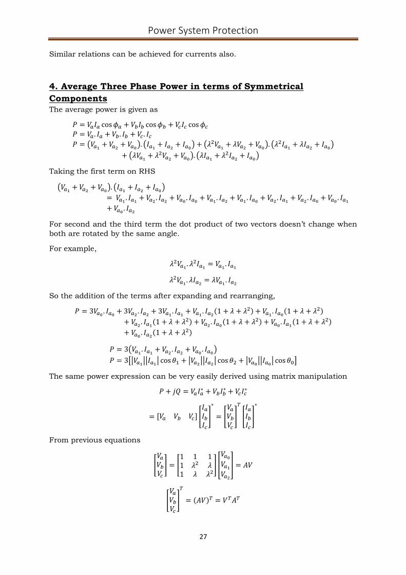
4. Average Three Phase Power in terms of Symmetrical
Components
The average power is given as
Taking the first term on RHS
For second and the third term the dot product of two vectors doesn’t change when
both are rotated by the same angle.
For example,
So the addition of the terms after expanding and rearranging,
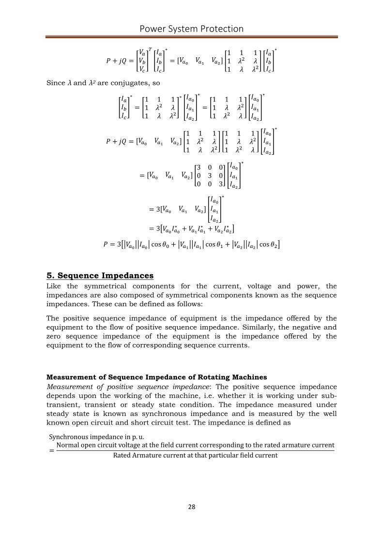
The same power expression can be very easily derived using matrix manipulation
From previous equations
Power System Protection
28
Since λ and λ2 are conjugates, so
5. Sequence Impedances
Like the symmetrical components for the current, voltage and power, the
impedances are also composed of symmetrical components known as the sequence
impedances. These can be defined as follows:
The positive sequence impedance of equipment is the impedance offered by the
equipment to the flow of positive sequence impedance. Similarly, the negative and
zero sequence impedance of the equipment is the impedance offered by the
equipment to the flow of corresponding sequence currents.
Measurement of Sequence Impedance of Rotating Machines
Measurement of positive sequence impedance: The positive sequence impedance
depends upon the working of the machine, i.e. whether it is working under sub-
transient, transient or steady state condition. The impedance measured under
steady state is known as synchronous impedance and is measured by the well
known open circuit and short circuit test. The impedance is defined as

Power System Protection
29
Method of test for synchronous Impedance: The machine here is run at a proper
direction with the help of a prime mover. The shorting link switch is kept in off
position to perform open circuit test and noted the readings of the voltmeter by
varying the field current. Similarly, the short circuit test is done by putting the
shorting switch on and noting the readings of armature current with the variation
of the field current.
Figure 2 Connection Diagram for open circuit and short circuit test of an alternator
Measurement of Negative sequence Reactance: It is the impedance offered to the
flow of negative sequence current.
Figure 3 Measurement of negative sequence impedance
The machine here is driven at rated speed, and a reduced voltage is applied till the
rated current flows in the armature. When there is a flow of negative sequence
current there may be a possibility of hunting which would cause the pointer to
deflect. This allows the mean reading to be taken. The negative sequence
impedance is given by
Where V is the voltmeter and I is the ammeter reading.
This can be proved mathematically as follows
From the experiment, since it is similar to line-to-line fault with alternator
unloaded,

Power System Protection
30
Under these conditions, the positive sequence and negative sequence currents are
opposite to each other and the positive and negative sequence voltages are equal.
And the current in the ammeter
Current measured =
Measurement of zero sequence impedance: Zero sequence impedance is the
impedance offered by the machine to the flow of zero sequence current. This
impedance depends on the distribution of the windings on the factors like pitch
and breadth factors. The value is much smaller as compared to zero and negative
sequences.
Figure 4 Measurement of Zero sequence impedance
The machine is at standstill and a reduced voltage is applied. The zero sequence
impedance is .
6. Fault Calculation
The faults in a power system can be classified as:
1. Shunt Faults
2. Series Faults
Shunt type of faults involve power conductors or conductors-to-ground or short
circuit between conductors. When the circuits are controlled by fuses and in which

Power System Protection
31
one or two phases of the circuit gets opened while the other phase is closed, such
type of faults is known as series faults.
Shunt faults may be classified as (i) Line-to ground fault; (ii) Line-to-line fault; (iii)
Double line to ground fault; and (iv) 3-phase fault. Of these, the first three are
unsymmetrical faults as the symmetry is distributed over one or two phases while
the 3-phase fault is a balanced fault.
Series faults are classified as: (i) one open conductor; and (ii) two open conductors.
These faults disturb the symmetry in one or two phases and are unbalanced faults.
We are mainly concerned with symmetrical faults.
Voltage of the neutral
The potential of the neutral when it is grounded through some impedance is not
equal to the ground potential under unbalanced operation. The potential of the
neutral is given as , where Zn is the neutral grounding impedance and the
In is the neutral current. Here negative sign is given as the current flows from the
ground to the neutral of the system and the potential of the neutral is lower than
the ground
Since the positive and negative sequence currents are absent through the neutral
are absent, hence the drops due to these currents are also zero. Also for the
balanced set of currents or voltages, the neutral is at the ground potential.
Therefore for positive and negative sequence networks, neutral of the system will be
taken as reference.
Reference of Voltages
The phase voltages at any point in a grounded system and their zero sequence
components of voltage will be referred to the ground at that point. The positive and
negative sequence components of voltage are referred to neutral. Therefore the
voltage to ground and voltage to neutral is use alternatively but for the zero
sequence system it is important to distinguish between the two terms.
7. Sequence network Equations
The equations will be derived for an unloaded transformer with neutral solidly
grounded, assuming that the system is initially balanced, i.e. the generated
voltages are of equal magnitude and displaced by 120˚.

Power System Protection
32
Figure 5 A balanced three phase system
Since the sequence impedances per phase are same for all three phase and we are
considering initially a balanced system, the fault analysis will be done on single
phase basis.
The positive sequence component of voltage at the fault point is the positive
sequence generated voltage minus the drop due to the positive sequence current in
the positive sequence impedance.
Similarly for the negative sequence component of voltage at the fault point is the
negative sequence generated voltage minus the drop due to the negative sequence
current in the negative sequence impedance.
Since the negative sequence voltage generated is zero, therefore
Similarly for zero sequence voltage
Where Zg0 is the zero sequence impedance of the generator and Zn is the neutral
impedance.
The three sequence network equations are therefore
Where and the corresponding sequence networks for the unloaded
alternator is shown in the figure below
Power System Protection
33
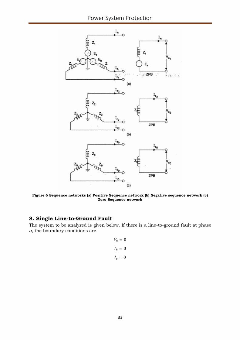
Figure 6 Sequence networks (a) Positive Sequence network (b) Negative sequence network (c) Zero Sequence network
8. Single Line-to-Ground Fault
The system to be analyzed is given below. If there is a line-to-ground fault at phase
a, the boundary conditions are

Power System Protection
34
Figure 7 A solidly grounded, unloaded alternator: L-G fault on phase a
The sequence network equations are
The solution of these six equations will give all the six sequence components of
voltage and current.
From the sequence current equations
Substituting the values of Ib and Ic in the above equations
Similarly according to the symmetrical component of voltage
Substituting the values of sequence voltages from the sequence network equation,
Since,
The above equation becomes

Power System Protection
35
From the above equation it is evident that to simulate an L-G fault all the three
sequence networks are required, and all these sequence networks are to be
connected in series, as the sequence currents are equal in magnitude and phase.
The interconnection is shown in the figure below
Figure 8 Interconnection of sequence networks for L-G fault
9. Line-to-Line Fault
As given in the figure below, the line-to-line fault takes place on phase b and c. The
boundary conditions are
And the sequence network equations are same as above. The solution of these six
equations will give the six unknowns.
Figure 9 L-L fault on an unloaded and neutral grounded alternator
Using the relation

Power System Protection
36
And substituting for Ia, Ib and Ic
So from the above relation, the zero sequence component of current is absent and
the positive and negative sequence is equal in magnitude but opposite in phase.
To simulate the L-L fault, the zero sequence network is not necessary and the
positive and negative sequence networks must be connected in phase opposition.
From the voltage equation,
Substituting the voltage relation
So, solving this we get
So the positive sequence component of voltage equals the negative sequence
component of voltage.
The interconnection of the sequence network can be simulated as below

Power System Protection
37
Figure 10 Interconnection of sequence networks for L-L fault
10. Double Line to Ground Fault
Assuming a double line to ground fault on phases b and c. The boundary
conditions are
And the sequence network equations are given.
Figure 11 A solidly grounded, unloaded alternator, L-L-G fault
The solution of these six equations will give six unknown symmetrical components.
Using the symmetrical components of voltage

Power System Protection
38
Using the above relations,
Similarly,
Now from the boundary condition,
Substituting the expression for sequence components of current
Solving the above equation we get,
From the above equation it is clear that all the three sequence networks are
required to simulate L-L-G fault and also that the negative and zero sequence
networks are connected in parallel. The interconnection of the network is shown
below
Figure 12 Interconnection of sequence networks for L-L-G fault

Power System Protection
39
The neutral current
11. Three Phase Fault
As per the figure given below, the boundary conditions are
Figure 13 A 3-phase neutral grounded and unloaded alternator 3-phase shorted
Since the phase currents are equal in magnitude, taking Ia as the reference
Using this relation
Similarly, for the sequence voltages, it can be found out as according to the
boundary condition
Since,

Power System Protection
40
The sequence networks is shown as below
Figure 14 Interconnection of sequence network 3-phase fault
12. Line-to-ground fault with ZF
When the fault impedance and the neutral impedance are included, the analysis of
the single line to ground fault can be analyzed as follows
The boundary conditions are
From the above equations, the sequence components can be derived as
The fault diagram and the interconnection is given below

Power System Protection
41
Figure 15 (a) A 3 phase unloaded with neutral grounded through impedance Zn and fault impedance ZF, L-G fault (b) Interconnection of sequence network for L-G fault
13. Line-to-line fault with ZF
The boundary conditions for the same are
And the sequence network equations
By using the symmetrical component analysis, we get
Using the above boundary condition, we get
Substituting the values by sequence networks, we get

Power System Protection
42
The interconnection is shown in the figure below
Figure 16 (a) L-L fault; (b) Interconnection of sequence network, fault impedance ZF, L-L fault
14. Double Line to Ground fault with ZF
The boundary condition for this type of fault is
Figure 17 L-L-G fault. Fault impedance ZF and neutral impedance Zn.
And the sequence network equations
We know that
Power System Protection
43
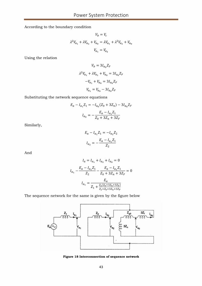
According to the boundary condition
Using the relation
Substituting the network sequence equations
Similarly,
And
The sequence network for the same is given by the figure below
Figure 18 Interconnection of sequence network

Power System Protection
44
15. Faults in Power Systems
The faults in the power system are analyzed by making use of Thevenin’s theorem
about the point of fault location. The theorem is important as it can determine the
changes in currents and voltages of a linear network when additional impedance is
added between two nodes of the network.
To determine the distribution in current and voltage in the system, the distribution
in each of the sequence networks must be determined. The Thevenin’s equivalents
of positive, negative and zero sequence networks are equivalent to those of the
networks for a single generator.
Considering the system given below, it is needed to find the Thevenin equivalent
network for determining the positive, negative and zero sequence networks about
the point P.
Figure 19 Single line diagram of a balanced 3-phase system
The Thevenin equivalent of the positive sequence network is obtained from the
positive sequence network. The Thevenin equivalent voltage source is the prefault
voltage at the fault point P and the equivalent impedance Z1eq is the impedance as
seen between the fault point and the zero potential bus shorting the voltage
sources.
Similarly, the Thevenin equivalent negative and zero sequence networks are
obtained from the negative and zero sequence networks respectively. Since the
system is balanced, no negative or zero sequence currents are flowing before the
fault occurs. Hence the prefault voltage of both negative and zero sequence are
equal to zero.
The Thevenin Equivalent Network can be given as below

Power System Protection
45
Figure 20 Thevenin’s equivalent network of (a) Positive network (b) Negative sequence network (c) Zero sequence network

Power System Protection
46
Chapter-5
APPARATUS PROTECTION
1. Introduction
The two major equipments in a power system are the generators and the
transformers. Even though the occurrences of faults in these are very less as
compared to that of the lines, the damage due to these faults is severe in lieu of
time and money as compared to that of the lines. Rapid reclosing of circuit
breakers can clear the fault in case of lines and it helps in saving the amount of
damage. But in case of these apparatus, it needs the aid of some attention or
supervisory staff. Therefore fast clearing of the faults is necessary to minimize the
damage and reduces the interruption to power services from reduced voltage and
instability.
2. Transformer Protection
Nature of Transformer Faults
Power Transformers generally develop rare faults as it is static, totally enclosed and
oil immersed but if these faults sustain the results may be serious unless the
transformer is disconnected. The faults that generally occur in the transformer can
be divided as:
1. Faults in auxiliary equipment which is a part of the transformer
2. Faults in the transformer winding and connections
3. Overloads and external short circuits.
Faults in Auxiliary Equipment
The detection of faults in auxiliary equipment is necessary to prevent ultimate
failure of the main transformer windings. In these the components are
(i) Transformer oil: Oil is used as an insulator in transformer. So when low
oil is present the live parts and the bushing leads gets exposed which are
supposed to be beneath the oil. Oil level can be determined by the means
of alarm indicators for immediate attention.
(ii) Gas cushion: The presence of oxygen or moisture may lead to
deterioration of the transformer oil. Hence exclusion of this presence is
necessary. Since the operating pressure varies within the tank, hence
sealing of the tank is not an option. Pressure indicators and conservators
are used to counter the expansion and contraction of oil. Whereas silica
gel is provided in the breathing vent to absorb the moisture content.
Sometimes a nitrogen cylinder is provided to provide an inert atmosphere
maintaining the pressure between 0.5 and 0.8 atm.
(iii) Oil pumps and forced air fans: The top oil temperature normally gives the
indication of the load on the transformer. A rise in temperature would
indicate an overloading situation or due to the fault in cooling system. A

Power System Protection
47
thermometer with alarm contacts will indicate the temperature rise in oil
due to any of these faults.
(iv) Core and winding insulations: These faults can turn into major faults if
not taken care of. Insulation failures may develop if
(a) The insulation of the laminations and core bolts may be of poor
quality.
(b) Poor quality of insulation between windings or between winding and
the core.
(c) Badly made joints or connections.
Winding Faults
Electrical Faults that can cause immediate serious damage and are determined by
the presence of unbalanced current or voltage may be divided into following
classes:
(i) Faults between adjacent turns or parts of coils such as phase-to-phase
faults on the HV and LV external terminals or on the winding itself or
short circuits between turns of HV and LV windings.
(ii) Faults to ground or across complete windings such as phase-to-earth
faults on either HV or LV side.
A short circuit between turns can start with a point contact resulting from
mechanical forces or insulation deterioration due to excessive overload. The
puncture of the turn insulation would cause a path through which the normal
frequency voltage can maintain an arc. But if the voltage is insufficient to maintain
the arc, it would be quenched by the oil present.
In the second case the ground faults are easy to detect as they are characterized by
emission of large amount of gas due to decomposition of oil as well as in large
values of fault currents. Rapid clearance is necessary to avoid excessive damage
and to maintain stability.
Overload and External Short Circuits
Overloads can be persistent in the system provided the temperature rise in the
windings is within the limits. Excessive overloading can cause deterioration in
insulation and subsequent failure. An alarm indication can be initiated when the
temperature limits exceed. External short circuits may only be limited by the
transformer reactance, so a low value would result in excessive fault currents.
Differential Protection of Transformers
The best way of protection of any apparatus against an internal fault is by the
method of differential protection scheme since it covers the apparatus’ zone of
protection. So for a transformer having ratings of 5 MVA and above, the differential
scheme serves as an important protection against internal phase-to-phase and
phase-to-earth faults. Any fault in the protected part would result in the deviation

Power System Protection
48
of the current intensities at the input and output. So the result of this unbalance
current can be employed for the tripping of the relay. For this reason the
differential scheme combines the characteristics of selectivity and highest tripping
time of the relay. A particular differential scheme is given below for a three-phase
star delta transformer.
Figure 21 Differential Protection Scheme of star-delta transformer
For the relay to detect 0 spill current in normal operation, the currents incoming
from both the CTs should be in direct opposition. Since in a star delta transformer
the line currents have a displacement of 30˚, so the CTs have to be connected in
delta on the star side of the transformer and in star for the delta side to avoid any
spill current through relay in normal operation. Another advantage of this
connection is the avoiding of triplet harmonics to appear on the line currents due
to delta windings.
Problems Encountered in Differential Protection of Transformer
Even though setting of the ratios are done the scheme also suffers from drawbacks
in it like
(i) Unmatched characteristics of CTs: The differential scheme employed for
protection fails in the case of different CT ratio characteristics. Since the
saturation characteristics are different, if they are not avoided would
result in appreciable amount of spill current flowing through the relay.
(ii) Ratio change as a result of tapping: Most of the power transformers are
provided with a tap changing equipment used for altering the turns ratio.
It is impracticable to change the CT ratio for compensating this effect of
tap changers. Biased relay can be employed for the overall protection of
variable-ratio transformers.
(iii) Magnetizing Inrush current: When the transformer is re-energized, the
transient inrush of the magnetizing current flowing is as high as ten

Power System Protection
49
times the full load current as it depends on the flux trapped in the core of
the transformer and the instant of the voltage cycle at which it is
switched. Even though it’s not a faulty condition, but depending on the
magnitude of the current the differential scheme would trip.
Percentage or Biased Differential Relays
Since there is a mal-operation of the normal differential scheme and their
associated drawbacks in the through fault and variable tap changing conditions,
the scheme is modified by providing a restraining winding which is energized by the
through current. This makes the operating winding biased or in other words it is
made to operate by some percentage of the through current. This makes the relay
more sensitive at low current without tripping for external fault.
If the ratio of restraining and operating coils is given as T, i.e.
Then the criterion for operation for a static comparator is:
Or for an electromagnetic comparator
The value of this turns ratio T is generally 0.05 for generators and between 0.1-0.4
for transformers. Higher values are used if the transformer ratio is varied by tap
changing equipment.
Figure 22 Biased Differential Protection for a transformer

Power System Protection
50
Figure 23 Biased Characteristics of biased differential relay for transformer protection. Setting 50% and bias 20%
Figure 2 shows the single line diagram for the biased differential scheme for the
transformer. Figure 3 gives the bias characteristics for a typical relay.
Methods for Preventing Operation on Inrush Currents
Magnetizing inrush currents is rich in harmonics unlike that in internal faults
where the current is sinusoidal. So modifications are made in the construction of
the relay. Since, the inrush current is rich in harmonics; the operating current is
made to filter out these harmonics before being fed to the operating coil. This helps
in the high speed and low operating current condition. Some of the methods are:
(i) Even Harmonic cancellation: For a typical inrush current waveform the
harmonics as a percentage of fundamental is given as
HARMONICS
Component Fundamental D.C. 2nd 3rd 4th 5th 6th 7th
Typical Value percent
100 55 63 26.8 5.1 4.1 3.5 2.5
In this the 3rd harmonics and its multiples are removed since the
connections are made in delta on the transformer for star connected CTs
and CTs in delta for the star side of the transformer. The dc components
and even harmonics can be cancelled out in the operating circuit of the
rectifier bridge relay and can be diverted on to the restraining circuit.
Since the magnitudes of the 5th and 7th are small so they can be ignored.
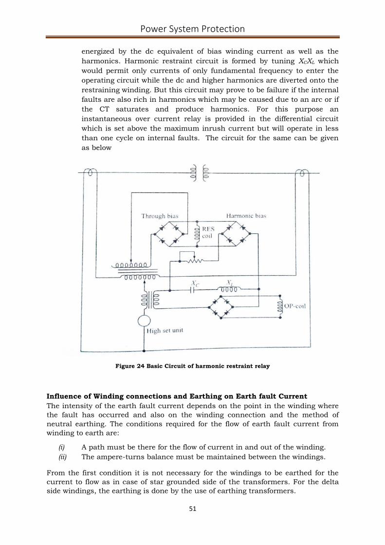
(ii) Harmonic restraint: This is the most extensively used methods for making
the relays immune to harmonics caused by inrush. The restraint coils is
Power System Protection
51
energized by the dc equivalent of bias winding current as well as the
harmonics. Harmonic restraint circuit is formed by tuning XCXL which
would permit only currents of only fundamental frequency to enter the
operating circuit while the dc and higher harmonics are diverted onto the
restraining winding. But this circuit may prove to be failure if the internal
faults are also rich in harmonics which may be caused due to an arc or if
the CT saturates and produce harmonics. For this purpose an
instantaneous over current relay is provided in the differential circuit
which is set above the maximum inrush current but will operate in less
than one cycle on internal faults. The circuit for the same can be given
as below
Figure 24 Basic Circuit of harmonic restraint relay
Influence of Winding connections and Earthing on Earth fault Current
The intensity of the earth fault current depends on the point in the winding where
the fault has occurred and also on the winding connection and the method of
neutral earthing. The conditions required for the flow of earth fault current from
winding to earth are:
(i) A path must be there for the flow of current in and out of the winding.
(ii) The ampere-turns balance must be maintained between the windings.
From the first condition it is not necessary for the windings to be earthed for the
current to flow as in case of star grounded side of the transformers. For the delta
side windings, the earthing is done by the use of earthing transformers.

Power System Protection
52
Star Winding with Resistance Earthed Neutral
In the case of resistance earthed neutral on the star side the magnitude of fault
current depends on the value of earthing resistance and is proportional to the
distance from the neutral end of the winding where the fault has occurred. If we
consider a delta star transformer, having a neutral earthed resistor of 1:1 voltage
ratio or the turns ratio on the primary to secondary side is √3:1. So for an earth
fault current IF at 100% of the winding on the secondary side the primary current
corresponding to the same would be 1/√3 times the fault current on the secondary,
i.e., (1/√3)IF. Now as the fault position on the secondary varies, the magnitude of
the fault current as well as the effective turns ratio between the primary and the
secondary varies. For example, if the earth fault occurs at x% of the winding, the
current on the secondary side would be (x/100) IF. Hence the effective turns ratio
would be √3: x/100, since x% of the winding would be active through which the
current flows. This results in primary current having a value (x/100)2IF/√3. Thus
the primary current is proportional to square of the percentage of winding that is
short circuited. The variation is shown in the figure below.
Figure 25 Transformer earth fault for resistance-earthed star winding
Star Winding with Neutral Solidly Grounded
The earth fault current unlike is resistance earthed is limited only by the
impedance of the winding itself, and since the impedance is a variable quantity
depending on the amount of winding that is faulted, the current no longer bears a
linear relationship. The reason is that the leakage reactance of the faulted winding

Power System Protection
53
is more near to the star point, but the reactance of the other windings are reduced
owing to the change in the transformation ratio. So the minimum fault occurs close
to the middle of the winding.
Figure 26 Transformer earth fault for solidly earthed star winding
Delta Winding
The minimum voltage that can appear in the delta winding is only half the phase
voltage and occurs at the midpoint of the winding. If the windings are not
resistance earthed, depending on the leakage reactance the current may rise to
about 200% of the full load current. If resistance earthing is employed the net
impedance rises by the vector addition of resistance with the net reactance. But if
the resistance is made to counter the orders of full load current, the minimum
current that can flow would be V/2R.

Power System Protection
54
Figure 27 Transformer earth fault for a delta winding system, resistance earthed
Overcurrent and Earth Fault (Unrestricted)
The Overcurrent protection can be done by the use of IDMT relays for protection
against excessive overloads and external short circuits. This protection scheme acts
as a backup protection for the transformer. The current setting is so chosen that it
would cater for above the permitted overload allowance and below the minimum
short circuit current. This types of relay is kept on the supply side and would
operate for both the LV and HV side breakers.
Tank Leakage Protection
If the tank is not highly insulated or where the insulation resistance is of 10 ohms,
there might exist a chance of insulation breakdown between the transformer tank
and earth. So an earth fault protection scheme can be employed by connecting a
relay to the CT secondary whose primary is connected between the tank and the
ground.
Restricted Earth Fault Protection
This type of protection if there is an earth fault within the internal zone of
protection of the transformer. In this CTs are connected in each phase and the
secondary of each CT is connected in parallel. The connections are made so
because this leads to the addition of currents which is proportional to the zero
sequence currents, which exists if and only if there is an earth or ground fault.
When it is an internal fault the current adds up to twice the fault current. But in
case of external faults this sum is zero. A typical connection in restricted earth
fault protection for transformer is given as below

Power System Protection
55
Figure 28 Restricted Earth Fault Protection: (a) neutral earthed within the protected zone; (b) neutral not earthed within the protected zone
Figure 29 Differential and restricted earth-fault protection of a star-delta transformer
Gas Actuated Relays
When there is a fault in the transformer tank, it leads to the gas formation in the
tank itself, which is slow for the incipient faults and violently for heavy faults. The
gas which is formed due to decomposition of the oil which is caused by the high
amount of heat produced by the local currents can be made use of for detecting the
faults. One of the famous relays in this context is the Buchholz Relay.

Power System Protection
56
It is the simplest type of relay consisting of a chamber connected between the
conservator and the transformer main tank. Within the chamber, it consists of two
cylindrical floats, one at the top of the chamber and the other opposite orifice of the
pipe to the transformer. In the normal conditions the floats are up, but when there
is an incipient fault like an inter turn fault, the gas which is formed due to it moves
up in the direction of conservator. On moving up they are trapped inside the relay
chamber and thereby reducing the oil level. This results in upper float to fall down
which was initially kept up by the oil level. When this float reaches a predetermined
distance, it closes the contact and gives an alarming signal to the personnel.
But when the fault is heavy, the surge of gas and oil engages the lower float also to
be pushed down which in turn trips the circuit breaker.
Figure 30 Buchholz Relay
Transformer Feeder Protection
In a method to supply bulk power from a major switching station, sometimes the
transformer is connected directly without any provision of switchgear. Even though
it is cost effective, but it would require adequate protection schemes. In addition to
the protection provided for transformer and feeder when considered separately, the
need for some means of inter-tripping between the HV and LV circuit breakers
becomes essential.
For countering this, two basic systems of protection can be done: unit and non-unit
systems. In unit systems, the differential scheme can be applied separately for the
transformer and feeder or considering both the transformer and feeder as an overall
unit. In both the cases pilot wire is required. In non-unit systems, it provides back
up protection for both the faults occurring outside the protected zone as well as
that in the zone faults.
Power System Protection
57
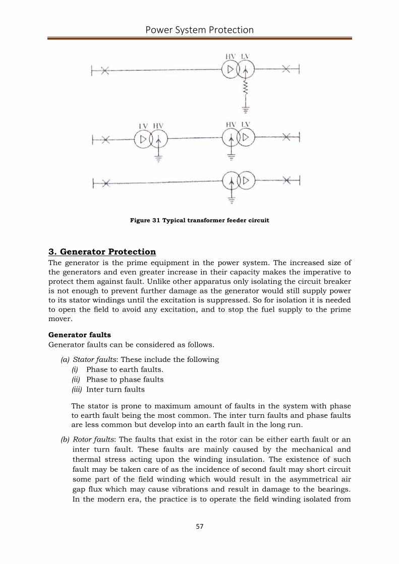
Figure 31 Typical transformer feeder circuit
3. Generator Protection
The generator is the prime equipment in the power system. The increased size of
the generators and even greater increase in their capacity makes the imperative to
protect them against fault. Unlike other apparatus only isolating the circuit breaker
is not enough to prevent further damage as the generator would still supply power
to its stator windings until the excitation is suppressed. So for isolation it is needed
to open the field to avoid any excitation, and to stop the fuel supply to the prime
mover.
Generator faults
Generator faults can be considered as follows.
(a) Stator faults: These include the following
(i) Phase to earth faults.
(ii) Phase to phase faults
(iii) Inter turn faults
The stator is prone to maximum amount of faults in the system with phase
to earth fault being the most common. The inter turn faults and phase faults
are less common but develop into an earth fault in the long run.
(b) Rotor faults: The faults that exist in the rotor can be either earth fault or an
inter turn fault. These faults are mainly caused by the mechanical and
thermal stress acting upon the winding insulation. The existence of such
fault may be taken care of as the incidence of second fault may short circuit
some part of the field winding which would result in the asymmetrical air
gap flux which may cause vibrations and result in damage to the bearings.
In the modern era, the practice is to operate the field winding isolated from

Power System Protection
58
the earth so that a single fault between field winding and rotor body due to
insulation breakdown can be tolerated.
(c) Abnormal running conditions: The abnormal running conditions that can
occur are: (i) loss of excitation, (ii) unbalance loading, (iii) overloading, (iv)
failure of prime mover, (v) over speeding, and (vi) over-voltage.
Field failure may occur due to a faulty field breaker. When a generator loses its
excitation, the amount of reactive power supplied to the system is lost. Instead it
would draw excitation from the system while delivering real power at leading power
factor. This leads to an operation of an induction generator where the speed is
slightly increased. Also due to loss of excitation there would be a voltage fall which
would lead to loss of synchronism. The situation may also lead to overheating in
rotor and damper windings.
If there is any unbalance in the system due to a phase fault or due to the
unbalance loading, it gives rise to negative sequence currents. It produces an
armature reaction field which rotates in a direction opposite to that of the rotor and
hence produces a flux which is twice the frequency. These currents are linked to
the rotor and damper windings which produces heating in the windings.
When there is an overloading in the generator, it would draw more current and as a
result would produce more heating loss in the stator which may damage the
insulation.
When there is a failure of prime mover, the real power delivering capacity is lost
and instead it would draw power from the system making it to run as a motor. This
affects the drive of the system due to opposite torque being applied on to the shaft.
When a sudden load is removed then according to the AGC control, the machine is
going to over speed. This happens mainly in the hydraulic generators since the
water flow cannot be immediately stopped for the inertia in water motion.
Over voltages may occur due to the failure in the AVR control in the excitation or
may be due to over speeding.
Stator Protection
As discussed, the most common fault that happens in stator is the earth faults.
Since an earth fault near the generator is very critical as the magnitude of the
current is very high, so the current is limited by either a resistance connected in
the neutral circuit. Depending on this value the current can be limited to either
200 to 250 A which is done by resistor earthing or 4 to 10 A by distribution
transformer earthing. Even though the second method has an advantage of
reducing the damage on to the stator core, the practicability of this method is
limited if the transformer is connected in delta.
In the resistor earthing, the resistance is connected between the neutral and the
ground and the CT is mounted on the neutral with an IDMT or an instantaneous
attracted armature type relay. The maximum value of resistance is given by

Power System Protection
59
Where C is the capacitance of the stator circuit to earth per phase in microfarad
and f is the system frequency.
Figure 32 Location of E/F relay in a resistance earthed generator
If the neutral is earthed through the primary winding of a distribution transformer,
earth-fault protection is provided by connecting an over-voltage relay across its
secondary, then the maximum value of resistance is equal to
Where N is the turn ratio of the transformer.
Generator differential protection: The best form of protection for the stator windings
against all the internal faults is by the use of differential protection. The relay
recommended for this application is instantaneous attracted armature type which
is immune to ac transients and has the high speed feature if the CTs are
reasonably matched. But when the CTs have dissimilar characteristics, biased
differential relay can be applied as it would result in high amount of spill current
flowing through the relay.
A particular longitudinal biased differential relay protection scheme for the
generator is given as below

Power System Protection
60
Figure 33 Percentage Biased differential relay
Stator Inter turn fault protection: An inter-turn fault occurring on the same phase of
the stator winding do not disturb the neutral current, hence by the use of
longitudinal differential relay it is not possible to detect such type of fault. This
results to another modification in the protection designing whereby we make the
transverse differential relay in case of the generators where the stators have two
windings per phase. The protection scheme is given as
Figure 34 Biased Transverse differential protection for inter turn fault protection for 2 winding stator
Wherever single winding is present the protection of generators against inter turn
fault is done by using zero sequence voltage caused by the reduction of emf in the
faulted phase. One of the connections is given as

Power System Protection
61
Figure 35 Inter Turn fault detection
Rotor Protection
The rotor windings as discussed earlier may be due to earth faults or open circuits.
The figure shows a modern method of rotor earth fault detection. The field is biased
by a dc voltage which causes current to flow through R for an earth fault.
Figure 36 Rotor Earth Fault Detection

Power System Protection
62
Loss of Excitation (Field Failure) Protection
As discussed, the loss of field circuit imposes the circuit to draw reactive VAR from
the system. This results in machine being operated as an induction generator. This
causes overheating in the circuit.
Loss of excitation is detected by the import of VAR indicating either actual or
prospective loss of synchronism. So the transients in such phenomena can be
allowed for 1 to 5 seconds in tripping sequence of the relay.
Due to the loss of excitation, there would be a drop in voltage and resulting in the
drop of current. This can be detected by an undercurrent moving coil relay in the
field circuit. Even this method is not suitable for generators having wide range of
operation in the field excitation.
The alternative solution that can be implemented is to apply an offset impedance or
mho relay. Its operating characteristics are arranged so that during conditions of
low excitation the effective generator impedance falls in the tripping zone.
Figure 37 Loss of excitation characteristic
Unbalance Loading Protection
An unbalance loading situation gives rise to negative sequence currents in the rotor
circuit which causes the heating in the circuit. The negative sequence currents
move at twice the supply frequency and follow a normal resistance law. In case of
high speed turbo generators this value is about 10 to 15% of the positive sequence
currents. The heating time constant is expressed by a rating equation
Where I2 is the negative sequence current based on per unit basis of continuous
maximum rating, t is the time in seconds and K is a constant usually varying
between 3 and 20.
An IDMT relay almost matches the heating characteristic of the negative sequence
current and can be detected by using an NPS filter as given below

Power System Protection
63
Figure 38 Protection against unbalanced load using negative sequence filter
Overload Protection
Overloading in the generator causes the stator windings to overheat. A provision of
overcurrent relay is not an obvious solution as it wouldn’t be able to discriminate
on the basis of time. The relay must be so chosen so as to counter for the slowest
relay on the system the generator is feeding. The simplest way is to detect the
overloading condition by the means of temperature detection coil connected in a
Wheatstone bridge.
Figure 39 Stator overheating protection using temperature detector coils
Prime mover protection
When there is a failure of prime mover, the machine starts to act as a motor
drawing real power from the system and thereby driving the prime mover. This
condition imposes a balanced load on the system. A reverse power relay can be
used to detect the tripping characteristics in this type situation since there is a
change in the direction of flow of power working over the full power factor range.

Power System Protection
64
Under such conditions, the load coming on the machine is very low of the order of
1% of the machine rating. Even though it is a small amount, the condition can be
harmful sometimes in case of steam turbines where the steam acts as coolant,
maintaining the turbine blades at a constant temperature and the failure of steam
results in overheating along with distortion of blades.
Figure 40 Reverse Power Relay operating characteristics
Over-speed Protection
Over speed protection is the most necessary protection in case of hydraulic
generator sets unlike the case in steam sets which as fast acting governors. A
provision of reverse or under power interlock relay is provided to prevent the main
generator CB from tripping in non emergency situations. A provision of centrifugal
switch is provided at the shaft which flies out and closes the valve when speed
exceeds 10%.
Overvoltage Protection
Overvoltage protection is provided on machines which are subjected to over speed
on loss of load. The relay is energized from a single phase voltage transformer,
having the characteristics similar to IDMT characteristics.
Protected Scheme for a Direct Connected Generator
Direct Connected generators normally of smaller ratings consists of the following
protections
(i) Unbiased differential protection
(ii) Back up overcurrent protection
(iii) Negative phase sequence protection
(iv) Standby earth fault
In addition to these protections the following may also be provided
(i) Field failure protection
(ii) Rotor earth-fault protection
(iii) Reverse power protection
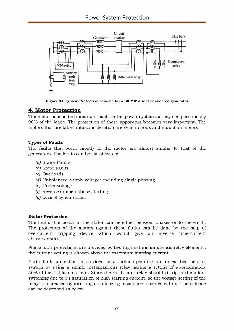
Power System Protection
65
Figure 41 Typical Protective scheme for a 30 MW direct connected generator
4. Motor Protection
The motor acts as the important loads in the power system as they compose mostly
90% of the loads. The protection of these apparatus becomes very important. The
motors that are taken into consideration are synchronous and induction motors.
Types of Faults
The faults that occur mostly in the motor are almost similar to that of the
generators. The faults can be classified as:
(a) Stator Faults
(b) Rotor Faults
(c) Overloads
(d) Unbalanced supply voltages including single phasing.
(e) Under voltage
(f) Reverse or open phase starting
(g) Loss of synchronism
Stator Protection
The faults that occur in the stator can be either between phases or to the earth.
The protection of the motors against these faults can be done by the help of
overcurrent tripping device which would give an inverse time-current
characteristics.
Phase fault protections are provided by two high-set instantaneous relay elements;
the current setting is chosen above the maximum starting current.
Earth fault protection is provided in a motor operating on an earthed neutral
system by using a simple instantaneous relay having a setting of approximately
30% of the full load current. Since the earth fault relay shouldn’t trip at the initial
switching due to CT saturation of high starting current, so the voltage setting of the
relay is increased by inserting a stabilizing resistance in series with it. The scheme
can be described as below

Power System Protection
66
Figure 42 Induction motor-protection relay
Rotor Protection
Any unbalance in the supply or in the loading pattern will cause high amount of
negative sequence current in the stator. This induces high frequency currents in
the rotor circuit also. The frequency of this current is (2-s) times the normal
frequency. The heating value of the negative sequence current is high as compared
to positive sequence current, which is proportional to (2-s) f (approximately 100 Hz)
a.c. resistance value. Hence motor protection must be taken into account the
allowable voltage unbalance without overheating.
Overload Protection
The overload protection of the motor is designed so as to match the heating curve
of the motor. The motor must not be allowed for most of the time for heating. For
this reason the characteristics of the relay must not be more than the heating
characteristics of the motor for protection. The protection must also have the
capability to adjust its characteristics and should not allow the motor to restart
until the motor winding temperature is high. For this reason the IDMT relay is best
suited for this purpose.
Figure 43 Operating time characteristic of IDMT relay induction type

Power System Protection
67
Unbalance and Single Phasing Protection
An unbalance in the system causes the negative sequence currents to flow in the
motor. This would result in overheating of the machine windings. Unbalanced loads
or accidental opening of one phase of the supply (single phasing) depending on the
load still keeps the motor running with the induction of negative sequence in the
motor.
For star connected motors the unbalance can be protected by two overload
elements. For delta connected motors such arrangement is satisfactory when the
motor is running for more than 70% of the full load. A better scheme for detecting
unbalance in motors is by the way of using bimetal strips as explained below:
In this arrangement, the bimetal relay has two slides S1 and S2 such that the slider
S1 is moved by the deflection of the bimetal strips, whereas the slider S2 is kept in
position due to non-bending of the bimetal strips. On symmetrical loading all the
three bimetallic strips bend equally and both sliders move equally in the same
direction by distance d thereby initiating the tripping. When there is a single
phasing in the system, so that phase remains cold while the other two phases gets
overloaded. This results in bending of these two phases while the other remains
fixed. Hence the slider S1 moves accordingly while the slider S2 is held by bimetal
strip of the cold phase. This bending initiates the tripping of the relay. Thus, the
bimetal relay responds accordingly in case of single phasing.
Figure 44 Bimetal relay with single phasing trip feature
In case of large motors the use of bimetal relay becomes sluggish because of the
level of fault current being high. In this case we make the use of thermistors which

Power System Protection
68
causes the tripping action due to the change in resistance. The figure below
illustrates the use of an over temperature protective scheme for a three phase over
DOL starting type induction motor which has the NTC type thermistors connected
in it.
Figure 45 Temperature operated scheme
Under voltage Protection
A motor working in over voltage situation would generally be associated with
overcurrent and thus can be protected by overload devices. A time delay is
generally given to avoid transient behaviour of the voltage drop.
Reverse Phase Protection
The direction of rotation of the motor changes if the phase sequence is changed. In
some motors this becomes very important. In order to ensure the direction of
rotation an induction disc, poly phase voltage relay is used to protect the motor
from starting when there is a mismatch of the sequence. Such a connection is
shown in the figure below, where the torque is proportional to the sine product of
two voltages. So when there is a mismatch of sequence, there would be no torque
and restrains the motor from operating.

Power System Protection
69
Figure 46 Open and reversed phase relay
Loss of synchronism
A synchronous motor becomes out of synchronism when there is a severe overload
or a reduction in the voltage. Such a condition would result in change in power
factor due to pole slipping and is detected by the relay. Such circuit is given below
where the voltage between two phases is measured and the current in third phase
is measured.
Figure 47 Out-of-step protection relay
5. Bus Faults
Bus zone protection includes the bus itself as well as circuit breakers,
disconnecting switches, instrument transformers and bus sectionalizing reactors.
These faults occurs rarely in the system but the provision of bus bar protection is
necessary at the large and important station as the bus zone fault would result in
interruption of high amount of power.

Power System Protection
70
Bus Zone Faults
The faults in the bus zone can be divided as follows:
(i) Failure of circuit breaker to interrupt fault current or failure to clear under
through fault conditions.
(ii) Insulation failure due to material deterioration.
(iii) Flashover causes by prolonged and excessive over voltages.
(iv) Errors in the operation and maintenance of switchgears.
(v) Foreign objects accidentally falling across bus bars.
Bus Backup Protection
When no separate protection is provided for the bus bars but there is a provision of
distance protection, so any fault that is occurring at the bus zone protection would
come under the zone 2 protection of the distance relay where it covers the bus bar
and the next line also. This is satisfactory for the small switchgear case but not in
the case of prime installations. Therefore a separate bus zone protection may be
provided for the same.
Differential Scheme of Bus Bar Protection
It is based on the simple circulating current principle that during the normal
condition or external fault condition, the incoming current must be equal to the
leaving current. Since the bus in a power system acts as a node in an electrical
circuit, if the summation of currents is not equal to zero, it means that there is a
short circuit due to ground fault or phase to phase fault. The differential scheme
can be given as below, whose CT ratio are given according to the highest current
that is flowing in the feeder circuits.
Figure 48 Differential Protection of a bus section

Power System Protection
71
Since the CTs used here are of the same ratio, when there is a through fault
condition, the magnetic conditions of the iron cored CTs would result in false
operation due to saturation. Even with biasing of the relay, the improvement is not
satisfactory.
An improvement can be done by the use of non iron cored CT also known as linear
coupler to overcome the difficulties of iron cored CTs. In this the secondary voltage
is proportional to the primary current. So when there is an external fault, the
addition of the voltages won’t result to zero since the current is still balanced, but
when there is an internal fault there is an unbalance in current and hence results
to some voltage in the linear coupler scheme.
Figure 49 Linear Coupler scheme
Frame Leakage Protection
It is possible to design a station so that the faults which develop are mostly earth
faults, by providing earthed metal barrier surrounding each conductor in the bus
structure. With this arrangement every fault that might occur must involve a
connection between the conductor and an earthed metal part.
The figure below shows the metal supporting structure also known as a fault bus
earthed through a CT. Sometimes, the structure is earthed by the means of
impedance connected in the neutral.
Figure 50 Frame leakage protection
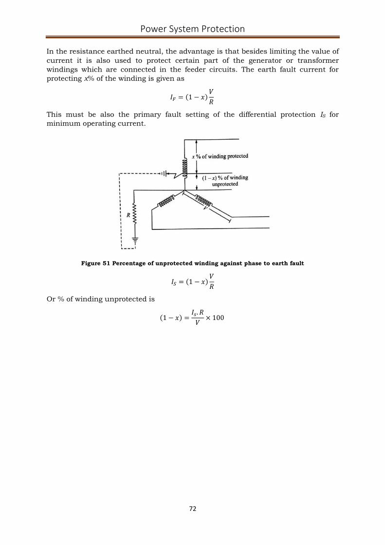
Power System Protection
72
In the resistance earthed neutral, the advantage is that besides limiting the value of
current it is also used to protect certain part of the generator or transformer
windings which are connected in the feeder circuits. The earth fault current for
protecting x% of the winding is given as
This must be also the primary fault setting of the differential protection IS for
minimum operating current.
Figure 51 Percentage of unprotected winding against phase to earth fault
Or % of winding unprotected is