power supply and fan module installation - cisco - … catalyst 3750-e and catalyst 3560-e switch...
TRANSCRIPT

Catalyst 3750-E and COL-9774-04
C H A P T E R3
Power Supply and Fan Module InstallationThis chapter describes how to remove and install a new or replacement power supply or fan module in a Catalyst 3750-E or Catalyst 3560-E switch. See these sections:
• Installation Overview, page 3-1
• Installing an AC-Power Supply, page 3-3
• Installing a DC-Power Supply, page 3-4
• Installing a Fan Module, page 3-10
Installation OverviewThis section describes the tools and equipment needed for installation, the applicable safety warnings, and the installation guidelines:
• Tools and Equipment, page 3-1
• Installation Guidelines, page 3-1
Tools and EquipmentObtain these necessary tools and equipment:
• Ratcheting torque screwdriver with a number-2 Phillips head that exerts up to 15 pound-force inches (lbf-in.) or 240 ounce-force inches (ozf-in.) of pressure. For 1150-W power-supply modules, the screwdriver shaft length should be at least 6-inches long.
• Power-supply power-cord retainer assembly in the switch accessory kit.
Installation GuidelinesTable 1-11 and Table 1-13 list the switches and the compatible power-supply modules. Observe these guidelines when removing or installing a power supply or fan module:
• Do not force the power supply or fan module into the slot. This can damage the pins on the switch if they are not aligned with the module.
• A power supply or fan module that is only partially connected to the switch can disrupt the system operation.
3-1atalyst 3560-E Switch Hardware Installation Guide

Chapter 3 Power Supply and Fan Module InstallationInstallation Overview
• Remove power from the power-supply module before removing or installing the module.
• The 24- and 48-port switch supports hot swapping of the power supply when the switch is connected to an RPS 2300. You can remove and replace the power supply without interrupting normal switch operation. When you insert a new power supply in the switch, there is a 5-second delay while the switch software polls the device. The switch power supply then automatically provides power, and the RPS 2300 is available to power other devices.
• The Catalyst 3560E-12D and 3560E-12SD switches support hot swapping of a power-supply module when one of the two power supplies is active. You can remove and replace the power supply without interrupting normal switch operation. When you insert a new power supply in the switch, there is a 5-second delay while the switch software polls the device.
• The Catalyst 3560E-12D and 3560E-12SD switches can operate with only one active power-supply module. However, two power supply modules must always be physically installed in the switch rear panel when the switch is operating, even if one module is defective. This is required to maintain adequate airflow in the chassis and prevent overheating. When the switch is running on only one power-supply module, redundant failover and load sharing is not available.
Caution Do not operate the Catalyst 3560E-12D or 3560E-12SD switch with one power-supply module removed from the rear panel. For proper chassis cooling, two power-supply modules must be installed in the switch rear panel.
• For the Catalyst 3560E-12D and 3560E-12SD switch power-supply modules, we recommend that you connect the power-supply modules to separate AC or DC circuits for optimal power reliability.
• The switch supports hot swapping of a fan module. When replacing a fan, you should complete the replacement procedure within 2 minutes to avoid overheating the switch.
• The Catalyst 3560E-12D and 3560E-12SD switch continues to operate when there is one failed fan, either a power-supply fan or a chassis cooling fan. If one fan fails, the switch returns an error message. If a second fan fails, either a power supply fan or a chassis cooling fan, the switch returns an error message, writes a failure log to flash memory, and shuts down.
• Make sure that all power supply and fan module captive screws are tightened before moving the switch.
• When replacing the 24- and 48-port switch 1150-W or 750-W power supply, verify that you are using the correct power cord (CAB-16AWG-AC, only in North America).
Warning Do not reach into a vacant slot or chassis while you install or remove a module or a fan. Exposed circuitry could constitute an energy hazard. Statement 206
Warning Only trained and qualified personnel should be allowed to install, replace, or service this equipment. Statement 1030
Warning Do not work on the system or connect or disconnect cables during periods of lightning activity. Statement 1001
3-2Catalyst 3750-E and Catalyst 3560-E Switch Hardware Installation Guide
OL-9774-04

Chapter 3 Power Supply and Fan Module InstallationInstalling an AC-Power Supply
Installing an AC-Power SupplyTo remove and install an AC-powered power-supply module, follow these steps:
Step 1 Turn off the power at its source. For Catalyst 3560E-12D and 3560E-12SD switches, also turn off the power supply on/off switch.
Step 2 If used, detach the power cord retainer assembly from the power cord.
Step 3 Remove the power cord from the power connector.
Step 4 For 24- and 48-port switches, use a Phillips screwdriver to loosen the two captive screws at the lower edge that secure the power supply to the switch chassis (Figure 3-1).
For Catalyst 3560E-12D and 3560E-12SD switches, use a Phillips screwdriver to loosen the captive screw at the left edge of the power supply (Figure 3-2).
Caution Do not leave the power-supply slot open for more than 90 seconds while the switch is operating.
Step 5 Remove the power-supply module from the power slot by pulling on the extraction handle.
Step 6 Insert the new power supply into the power-supply slot, and gently push it into the slot (Figure 3-1 and Figure 3-2). When correctly inserted, the power supply is flush with the switch rear panel. The 1150-W power-supply module extends 3.6 inches (9.14 cm) from the switch rear panel.
Figure 3-1 Inserting the AC-Power Supply in 24- and 48-Port Switches
Figure 3-2 Inserting the AC-Power Supply in Catalyst 3560E-12D and 3560E-12SD Switches
(Catalyst 3560E-12D Switch Shown)
Step 7 For 24- and 48 port switches, align the two captive screws with the screw holes. Using a ratcheting torque screwdriver, torque each screw to 7 lbf-in. (112 ozf-in.).
1581
22
AC OK PS OK
100-240 V10-5 A50-60 HZ
InputOK
OutputOK
CONSOLE
2020
47
3-3Catalyst 3750-E and Catalyst 3560-E Switch Hardware Installation Guide
OL-9774-04

Chapter 3 Power Supply and Fan Module InstallationInstalling a DC-Power Supply
For Catalyst 3560E-12D and 3560E-12SD switches, align the captive screw with the screw hole. Using a ratcheting torque screwdriver, torque the screw to 4 lbf-in. (64 ozf-in.)
Step 8 (Optional) Assemble the AC power cord retainer with the large end of the plastic bushing facing away from the switch. Position the assembly on the power cord, and insert the wire bales into the slots on the switch rear panel (Figure 3-3).
Figure 3-3 AC-Power Supply with Power Cord Retainer
Step 9 Connect the power cord to the power supply and to an AC-power outlet. Turn on the power at the power source. For Catalyst 3560E-12D and 3560E-12SD switches, also turn on the power supply on/off switch.
Step 10 For 24- and 48-port switches, confirm that the power supply AC OK LED is green. See Table 1-12 for a description of the module LEDs.
For Catalyst 3560E-12D and 3560E-12SD switches, confirm that the power supply Input OK LED is green. See Table 1-14 for a description of the power supply LEDs.
Installing a DC-Power SupplyTo connect the switch to a DC-input power source, follow these steps:
1. Preparing for Installation, page 3-5
2. Grounding the Switch, page 3-5
3. Installing the DC Power Supply in the Switch, page 3-8
4. Wiring the DC-Input Power Source, page 3-9
Warning An exposed wire lead from a DC-input power source can conduct harmful levels of electricity. Be sure that no exposed portion of the DC-input power source wire extends from the terminal block plug. Statement 122
Warning Before connecting or disconnecting ground or power wires to the chassis, ensure that power is removed from the DC circuit. To ensure that all power is OFF, locate the circuit breaker on the panel board that services the DC circuit, switch the circuit breaker to the OFF position, and tape the switch handle of the circuit breaker in the OFF position. Use a voltmeter to test for 0 (zero) voltage at the power terminals on the chassis. Statement 196
1577
06
AC OK PS OK
100-240 V10-5 A50-60 HZ
3-4Catalyst 3750-E and Catalyst 3560-E Switch Hardware Installation Guide
OL-9774-04

Chapter 3 Power Supply and Fan Module InstallationInstalling a DC-Power Supply
Warning This product relies on the building’s installation for short-circuit (overcurrent) protection. Ensure that the protective device is rated not greater than: 15 A. Statement 1005
Warning A readily accessible two-poled disconnect device must be incorporated in the fixed wiring. Statement 1022
Note The grounding architecture of this product is DC-isolated (DC-I)
Preparing for InstallationObtain these necessary tools and equipment:
• Ratcheting torque screwdriver with a number-2 and a number-1 Phillips head that exerts up to 15 pound-force inches (lbf-in.) or 240 ounce-force inches (ozf-in.) of pressure.
• Panduit crimping tool with optional controlled-cycle mechanism (model CT-720, CT-920, CT-920CH, CT-930, or CT-940CH).
• Wire-stripping tools.
• 12-gauge copper ground wire (insulated or noninsulated) when using the single-ground connection.
• 6-gauge copper ground wire (insulated or noninsulated) when using the dual-ground connection.
• Ground lug screw and lug ring in the switch accessory kit. For a dual-ground connection on 24- and 48-port switches, also use the dual-ground adaptor and dual-hole lug from the DC power supply accessory kit.
• Four leads of 16-gauge copper wire.
• Four round eyelet terminals or four fork-type terminals from the DC power supply accessory kit.
Grounding the Switch
To make sure that the equipment is reliably connected to earth ground, follow the grounding procedure instructions and observe these warnings:
Warning This equipment must be grounded. Never defeat the ground conductor or operate the equipment in the absence of a suitably installed ground conductor. Contact the appropriate electrical inspection authority or an electrician if you are uncertain that suitable grounding is available. Statement 1024
Warning When installing or replacing the unit, the ground connection must always be made first and disconnected last. Statement 1046
3-5Catalyst 3750-E and Catalyst 3560-E Switch Hardware Installation Guide
OL-9774-04

Chapter 3 Power Supply and Fan Module InstallationInstalling a DC-Power Supply
Follow these steps to install either a single-ground lug or a dual-ground lug on the switch. Make sure to follow any grounding requirements at your site.
Step 1 Locate the ground lug screw and the lug ring in the switch accessory kit. For a dual-ground connection, locate the dual-ground adaptor (only 24- and 48-port switches) and dual-hole lug that ships with the DC-power-supply module.
Step 2 If your ground wire is insulated, use a wire stripping tool to strip the 12-gauge or 6-gauge ground wire to 0.5 inch (12.7 mm) ± 0.02 inch (0.5 mm) (Figure 3-4). Use 12-gauge copper ground wire for the single-ground connection. Use 6-gauge copper ground wire for the dual-ground connection.
Figure 3-4 Stripping the Ground Wire
Step 3 Slide the open end of the ground lug over the exposed area of the wire.
Step 4 Using a Panduit crimping tool, crimp the ground lug to the wire (Figure 3-5).
Figure 3-5 Crimping the Ground Lug
Step 5 For 24- and 48-port switches, use the ground screw to attach the single-ground lug and the wire assembly or the dual-ground adaptor to the switch rear panel. For a dual-ground adaptor, attach the dual-hole lug and the wire assembly to the adaptor with the supplied nuts (Figure 3-6 and Figure 3-7).
For Catalyst 3560E-12D and 3560E-12SD switches, use the ground screw to attach the single-ground lug and the wire assembly, or use two ground screws to attach the dual-ground lug and the wire assembly to the switch rear panel.
Step 6 Using a ratcheting torque screwdriver, torque the ground-lug screws to 60 lbf-in. (960 ozf-in.) (Figure 3-6 and Figure 3-7).
Step 7 Connect the other end of the grounding wire to an appropriate grounding point at your site or to the rack.
InsulationWire lead
0.5 in. (12.7 mm) ± 0.02 in. (0.5 mm)
6052
8
2000
44
3-6Catalyst 3750-E and Catalyst 3560-E Switch Hardware Installation Guide
OL-9774-04

Chapter 3 Power Supply and Fan Module InstallationInstalling a DC-Power Supply
Figure 3-6 Attaching the Ground Lug and Wire Assembly on 24- and 48-Port Switches
Figure 3-7 Attaching the Ground Lug and Wire Assembly on Catalyst 3560E-12D and 3560E-12SD
Switches (Catalyst 3560E-12D Switch Shown)
1 Single-ground screw and lug ring
2 Dual-ground adaptor and dual-hole lug
FR
F 1575
47
1
2
1 Single-ground screw and lug ring1
1. See Figure 1-9 for the Catalyst 3560E-12SD ground location.
2 Dual-ground screw and lug ring1
2021
98
NSOLE
InputOK
OutputOK
NSOLE
InputOK
OutputOK
1 2
3-7Catalyst 3750-E and Catalyst 3560-E Switch Hardware Installation Guide
OL-9774-04

Chapter 3 Power Supply and Fan Module InstallationInstalling a DC-Power Supply
Installing the DC Power Supply in the Switch
To remove and install a DC-powered power-supply module, follow these steps:
Step 1 Turn off power at the DC circuits. To ensure that power is removed from the DC circuits, locate the circuit breakers for the DC circuits, switch the circuit breakers to the OFF position, and tape the circuit-breaker switches in the OFF position.
Step 2 Use a number-2 Phillips screwdriver to remove the plastic safety cover from the power supply terminal blocks.
Step 3 Use a number-1 Phillips screwdriver to remove the DC-input power wires from the power terminals.
Step 4 For 24- and 48-port switches, use a Phillips screwdriver to loosen the two captive screws at the lower edge that secure the power-supply module to the switch chassis.
For Catalyst 3560E-12D and 3560E-12SD switches, use a Phillips screwdriver to loosen the captive screw at the left edge of the power-supply module.
Step 5 Remove the power-supply module from the power slot by pulling on the extraction handle.
Step 6 Insert the new power supply into the power-supply slot, and gently push it into the slot (Figure 3-8 and Figure 3-9). When correctly inserted, the power supply is flush with the switch rear panel.
Figure 3-8 Inserting the DC-Power Supply in 24- and 48-Port Switches
Figure 3-9 Inserting the DC-Power Supply in Catalyst 3560E-12D and 3560E-12SD Switches
(Catalyst 3560E-12D Switch Shown)
Step 7 For 24- and 48 port switches, align the two captive screws with the screw holes. Using a ratcheting torque screwdriver, torque each screw to 7 lbf-in. (112 ozf-in.).
For Catalyst 3560E-12D and 3560E-12SD switches, align the captive screw with the screw hole. Using a ratcheting torque screwdriver, torque the screw to 4 lbf-in. (64 ozf-in.)
Step 8 Connect the input power as described in the “Wiring the DC-Input Power Source” section.
1581
23FRU CC 265WDC IN
PS OKA
+A
+ INPUT-36 to -72V /12A
OUTPUT265W MAX /22A
CONSOLE
InputOK
OutputOK
2020
48
3-8Catalyst 3750-E and Catalyst 3560-E Switch Hardware Installation Guide
OL-9774-04

Chapter 3 Power Supply and Fan Module InstallationInstalling a DC-Power Supply
Wiring the DC-Input Power Source
To wire the DC-power-supply module to a DC-input power source, follow these steps.
Step 1 Using a wire-stripping tool, strip each of the four wires coming from the DC-input power source to the appropriate length for either the round eyelet or the fork-type terminals.
Step 2 Using a Panduit crimping tool, crimp the terminals to the 16-gauge DC-power input wires.
Step 3 Connect the DC-input power terminals to the terminal blocks as shown in Figure 3-10 or Figure 3-11. Make sure to match the polarity (negative to negative, positive to positive) when connecting the wires to the terminal blocks.
Figure 3-10 DC Source A Isolated From Source B with No Common Ground, 24- and 48-port
Switches
Figure 3-11 DC Source A and Source B Connections, Catalyst 3560E-12D and 3560E-12SD
Switches
Step 4 Torque all terminal block screws to 5 lbf-in. (80 ozf-in.).
B+
1577
18
B-
+
A+
A-
+
1 Connect to grounded metal rack, or connect to earth ground if the switch is not installed in a grounded rack.
B+
B-
-
+
A+
A-
-
+
2023
13
1
3-9Catalyst 3750-E and Catalyst 3560-E Switch Hardware Installation Guide
OL-9774-04
Chapter 3 Power Supply and Fan Module InstallationInstalling a Fan Module
Step 5 Replace the terminal block plastic safety cover. For 24- and 48-port switches, torque the safety-cover screw to 10 lbf-in. (160 ozf-in.).
Step 6 Move the DC-power source circuit-breaker handles to the ON position.
Step 7 For 24- and 48-port switches, confirm that the power-supply DC OK LED is green. See Table 1-12 for a description of the module LEDs.
For Catalyst 3560E-12D and 3560E-12SD switches, confirm that the power-supply Input OK LED is green. See Table 1-14 for a description of the power supply LEDs.
Installing a Fan ModuleTo remove and install a fan module, follow these steps:
Step 1 For 24- and 48-port switches, use a number-2 Phillips screwdriver to loosen the two captive screws that secure the fan module to the switch chassis.
Caution You should replace the fan module within 2 minutes to avoid overheating the switch.
Step 2 For 24- and 48-port switches, remove the fan module by pulling on the extraction handle.
For Catalyst 3560E-12D and 3560E-12SD switches, remove the fan module by pinching and then pulling the extraction handle.
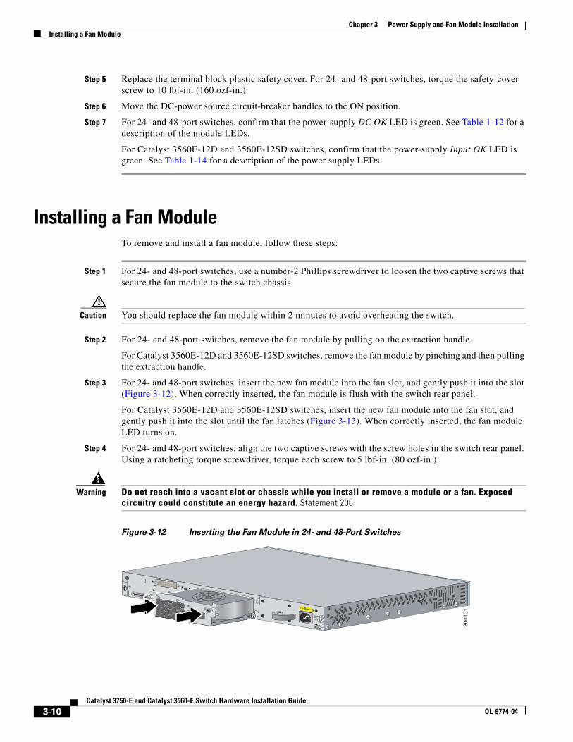
Step 3 For 24- and 48-port switches, insert the new fan module into the fan slot, and gently push it into the slot (Figure 3-12). When correctly inserted, the fan module is flush with the switch rear panel.
For Catalyst 3560E-12D and 3560E-12SD switches, insert the new fan module into the fan slot, and gently push it into the slot until the fan latches (Figure 3-13). When correctly inserted, the fan module LED turns on.
Step 4 For 24- and 48-port switches, align the two captive screws with the screw holes in the switch rear panel. Using a ratcheting torque screwdriver, torque each screw to 5 lbf-in. (80 ozf-in.).
Warning Do not reach into a vacant slot or chassis while you install or remove a module or a fan. Exposed circuitry could constitute an energy hazard. Statement 206
Figure 3-12 Inserting the Fan Module in 24- and 48-Port Switches
2001
01
AC OK PS OK
100-240V~1.0-5A50-60 HZ
3-10Catalyst 3750-E and Catalyst 3560-E Switch Hardware Installation Guide
OL-9774-04

Chapter 3 Power Supply and Fan Module InstallationInstalling a Fan Module
Figure 3-13 Inserting the Fan Module in Catalyst 3560E-12D and 3560E-12SD Switches
(Catalyst 3560E-12D Switch Shown)
InputOK
OutputOK
CONSOLE
2020
49
InputOK
OutputOK
3-11Catalyst 3750-E and Catalyst 3560-E Switch Hardware Installation Guide
OL-9774-04

Chapter 3 Power Supply and Fan Module InstallationInstalling a Fan Module
3-12Catalyst 3750-E and Catalyst 3560-E Switch Hardware Installation Guide
OL-9774-04