power management of wireless in-wheel motor with...
TRANSCRIPT

Power Management of Wireless In-Wheel Motorwith Dynamic Wireless Power Transfer
Takuma Takeuchi*, Takehiro Imura*, Hiroshi Fujimoto**, Yoichi Hori***The University of Tokyo
5-1-5, Kashiwanoha, Kashiwa, Chiba, 227-8561, JapanPhone: +81-4-7136-3873*, +81-4-7136-4131**, +81-4-7136-3846***
Email: [email protected],[email protected],
[email protected],[email protected]
Abstract—In-Wheel Motor (IWM) which is a driving system ofElectric Vehicles (EVs) is effective for improving driving stabilityof vehicle and reducing vehicle weight. However, IWM has notbeen put in practical use because of a possibility of power linesdisconnection. Therefore, we have proposed Wireless In-WheelMotor (W-IWM) in which Wireless Power Transfer (WPT) isused to remove these lines and to enhance practicability ofIWM. Moreover, we have proposed the advanced system of W-IWM which has Lithium-ion Capacitor (LiC) and circuit forDynamic Wireless Power Transfer (DWPT) on its wheel-side. Inthis paper, power management on the wheel-side is proposed. Byapplying this control method, efficiency of regenerative breakingcan be improved. Moreover, dynamic wireless power transferfrom road-side infrastructure can be achieved on the wheel-side.The proposed method is verified by simulations and experiments.
Index Terms—Wireless In-Wheel Motor, Wireless PowerTransfer, Lithium-ion Capacitor, Power management, State ofCharge, Dynamic Wireless Power Transfer
I. INTRODUCTION
Electric Vehicles (EVs) have been gathering a great dealof public attention from the perspective of environmentalperformance. However, due to a limited battery capacity, EVshas been only able for short distance. To deal with thisproblem, a number of researches have been done on effectivemotor driving for EVs [1] or driving range extension byvehicle motion control using In-Wheel Motor (IWM) [2], [3].IWM is one of the drive systems which equipped motors in itswheels. Owing to the independent toque control of each wheel,IWM can achieve high vehicle stability and long driving range[4]. Nevertheless, IWM has not been put to practical use dueto the risk of power lines disconnection mainly caused bycontinuous displacement between wheels and chassis whiledriving.
Therefore, we have proposed Wireless In-Wheel Motor (W-IWM) to solve this problem radically and to make IWMmore practical by using Wireless Power Transfer (WPT) viamagnetic resonance coupling [5], [6], [7]. We have alreadysucceeded in driving an experimental vehicle with the first trialunit of W-IWM. The first trial unit of W-IWM achieves 3.3kW/wheel and 89 % DC to DC efficiency from the chassis-side
(a) The first trial unit of W-IWM (b) Experimental vehicle
Fig. 1. The first trial unit of W-IWM and experimental vehicle.
to the wheel-side [8]. For more improvement of practicability,high power and further effective operation are expected.
Accordingly, the second trial unit of W-IWM (W-IWM2),which has Lithium-ion Capacitor (LiC) on the wheel-side forhigh output and a more efficient operation is under construc-tion. W-IWM2 enables more efficient regenerative breakingfrom wheel power to LiC because the regenerative power goesthrough less number of converters. Additionally, circuit forDynamic Wireless Power Transfer (DWPT) from a road-sidefacility is also added on wheel-side for more range extension.
As a result, W-IWM2 has multiple power sources [9],[10] on the wheel-side. Therefore, power-flow control ofthese power sources is required for stable motor driving.When too much/insufficient power are supplied from thesepower sources, the wheel-side DC-link voltage goes up/down.Moreover, regenerative power should goes through LiC forefficiency improvement. Therefore, power management on thewheel-side is necessary for W-IWM2.
In this paper, we propose power management method on thewheel-side by State of Charge (SOC) control of LiC. Applyingthis control to W-IWM2, a voltage of LiC is stabilized and out-put/input power of LiC can be controlled properly according toa load fluctuation. The proposed power management methodis verified by simulations and experiments.
II. WIRELESS IN-WHEEL MOTOR2 (W-IWM2)
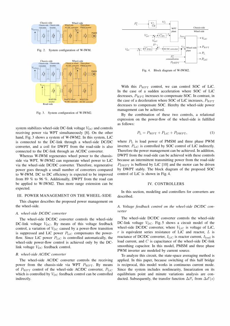
Fig. 1 shows the first trial unit and the experimental vehicle.Fig. 2 shows a system configuration of W-IWM. By applyinga hysteresis control to the wheel-side AC/DC converter, this
Chassis-side Wheel-side
Fig. 2. System configuration of W-IWM.
Chassis-side Wheel-side
Road-side
Fig. 3. System configuration of W-IWM2.
system stabilizes wheel-side DC-link voltage VDC and controlsreceiving power via WPT simultaneously [8]. On the otherhand, Fig. 3 shows a system of W-IWM2. In this system, LiCis connected to the DC-link through a wheel-side DC/DCconverter, and a coil for DWPT from the road-side is alsoconnected to the DC-link through an AC/DC converter.
Whereas W-IWM regenerates wheel power to the chassis-side via WPT, W-IWM2 can regenerate wheel power to LiCvia the wheel-side DC/DC converter. Therefore, regenerativepower goes through a small number of converters comparedto W-IWM. DC to DC efficiency is expected to be improvedfrom 89 % to 96 %. Additionally, DWPT from the road canbe applied to W-IWM2. Thus more range extension can beexpected.
III. POWER MANAGEMENT ON THE WHEEL-SIDE
This chapter describes the proposed power management onthe wheel-side.
A. wheel-side DC/DC converter
The wheel-side DC/DC converter controls the wheel-sideDC-link voltage VDC. By means of this voltage feedbackcontrol, a variation of VDC caused by a power-flow transitionis suppressed and LiC power PLiC compensates the power-flow. Since LiC power PLiC is controlled automatically, thewheel-side power-flow control is achieved only by the DC-link voltage VDC feedback control.
B. wheel-side AC/DC converter
The wheel-side AC/DC converter controls the receivingpower from the chassis-side via WPT PWPT. By meansof PWPT control of the wheel-side AC/DC converter, PLiC
which is controlled by VDC feedback control can be controlledindirectly.
Fig. 4. Block diagram of W-IWM2.
With this PWPT control, we can control SOC of LiC.In the case of a sudden acceleration where SOC of LiCdecreases, PWPT increases to compensate SOC. In contrast, inthe case of a deceleration where SOC of LiC increases, PWPT
decreases to compensate SOC. Hereby the wheel-side powermanagement can be achieved.
By the combination of these two controls, a relationalexpression on the power-flow of the wheel-side is fulfilledas follows:
PL = PWPT + PLiC + PDWPT, (1)
where PL is load power of PMSM and three phase PWMinverter. PLiC is controlled by SOC control of LiC indirectly.Therefore the power management can be achieved. In addition,DWPT from the road-side can be achieved with these controlsbecause an intermittent transmitting power from the road-sidePDWPT is buffered by LiC [10] and the motor can be drivenby DWPT stably. The block diagram of the proposed SOCcontrol of LiC is shown in Fig. 4.
IV. CONTROLLERS
In this section, modeling and controllers for converters aredescribed.
A. Voltage feedback control on the wheel-side DC/DC con-verter
The wheel-side DC/DC converter controls the wheel-sideDC-link voltage VDC. Fig. 5 shows a circuit model of thewheel-side DC/DC converter, where VLiC is voltage of LiC,r is equivalent series resistance of LiC and reactor, L isreactance of DC/DC converter, ILiC is reactor current, Iload isload current, and C is capacitance of the wheel-side DC-linksmoothing capacitor. In this model, PMSM and three phasePWM inverter are modeled by current source.
To analyze this circuit, the state-space averaging method isapplied. In this paper, because switching of this half bridgeis reciprocal, this model works in continuous current mode.Since the system includes nonlinearity, linearization on itsequilibrium point and minute variations analysis are con-ducted. Subsequently, the transfer function ∆Pv from ∆d′(s)

Fig. 5. Circuit model of wheel-side DC/DC converter.
to ∆vDC(s) is expressed as follows:
∆Pv =∆vDC(s)
∆d′(s)=
bp1s+ bp0s2 + ap1s+ ap0
(2)
ap1 =r
L, ap0 = − D′
LC
bp1 =ILiCC
, bp0 =rILiC −D′VDC
LC,
where ∆d′(s) is a minute variation of the duty ration ofthe upper arm switch and ∆vDC(s) is a minute variationof the wheel-side DC-link voltage. Based on this transferfunction, we design the PID controller such that closed-loopcharacteristic has quadrupole on real axis and discretized itwith Tustin conversion.
B. Power control on the wheel-side AC/DC converter
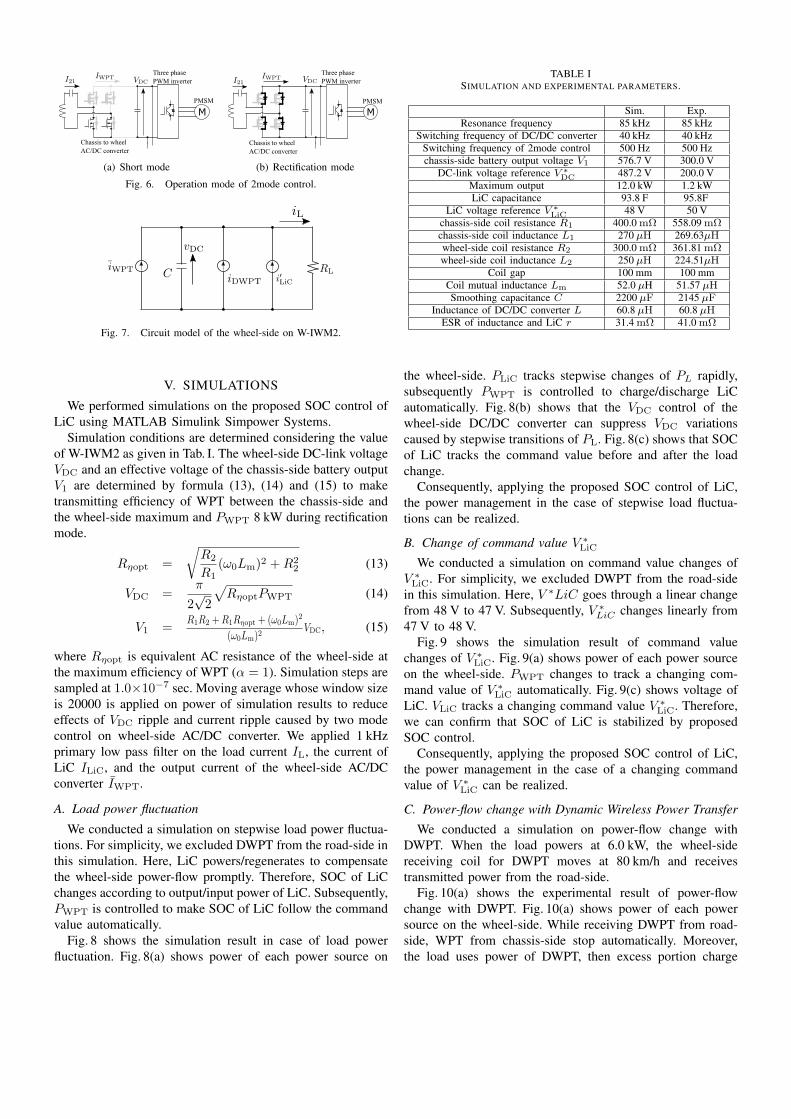
The wheel-side AC/DC converter controls the receivingpower from the chassis-side to the wheel-side by two modecontrol [11]. Fig. 6 shows operation modes of the wheel-sideAC/DC converter in two mode control.
Short modeLow side switches of the wheel-side AC/DC con-verter are turn on. Then the wheel-side receivercoil shorts from the wheel-side circuit as shown inFig. 6(a) and does not supply the transmitting powerfrom the chassis-side to the wheel-side.
Rectification modeThe wheel-side AC/DC converter operates as a rec-tifier as shown in Fig. 6(b). The wheel-side receivesthe transmitting power from chassis to wheel.
By converting two modes periodically, we are able to controlthe average output current of the wheel-side AC/DC converter.Assuming that the wheel-side coil current is a sinusoidalcurrent with the resonant frequency, an input voltage ofthe wheel-side AC/DC converter can be approached to itsfundamental harmonic. Moreover, an approximate value of aneffective current of the wheel-side coil I21 is determined asfollow:
I21 ≃ω0LmV11 − 2
√2
π R1VDCα
R1R2 + (ω0Lm)2, (3)
where ω0 is resonance angular frequency, Lm is mutualinductance between the chassis-side and the wheel-side coils,and R1, R2 are the chassis-side and the wheel-side coils
resistance respectively. An output current of the wheel-sideAC/DC converter IWPT on each mode is expressed as below.
IWPT =
0 (Short mode)2√2
π I21 (Rectification mode)(4)
Therefore, average output current of the wheel-side AC/DCconverter IWPT is expressed with α, which is time ration ofrectification mode.
IWPT = αIWPT (5)
Consequently, we can control an average output current of thewheel-side AC/DC converter IWPT and the receiving powerfrom the chassis-side via WPT PWPT by changing α.
Generating a command value of this two mode control fromVLiC makes SOC control of LiC possible. Assuming that theVDC control by the wheel-side DC/DC converter is valid,formula (6) is derived from formula (1) and the wheel-sidecircuit model can be expressed by Fig. 7.
IWPT + I ′LiC = IL (6)
I ′LiC is a output current of the wheel-side DC/DC converter.Assuming that a loss of the wheel-side DC/DC converter issmall enough, formula (7) is derived.
I ′LiCVDC = ILiCVLiC (7)
Furthermore, a relation expression of a LiC current ILiC andvoltage VLiC can be expressed as
ILiC = −CLiCdvLiC
dt. (8)
Therefore, from formula (6),(7) and (8),the following equa-tion is derived.
iWPT = (Cd
dt+
1
RL)vDC +
CLiC
vDCvLiC
dvLiCdt
− iDWPT (9)
By linearizing the formula above using Taylor expansion, atransfer function from ∆iWPT to ∆vLiC can be expressed as,
∆PSOC =∆vLiC∆iWPT
=VDC
2CLiCVLiCs. (10)
Consequently, we can design the PI controller for the circuitmodel expressed by formula (5) and (10) such that closed-lopepoles have dual pole pPI on real axis. Therefore, following PIgain are obtained.
KP =
√2πpPICLiCVLiCR1R2 + (ω0Lm)
2ω0LmV11VDC
(11)
KI =πp2PICLiCVLiCR1R2 + (ω0Lm)
2√2ω0LmV11VDC
(12)
Finally, this PI controller is discretized with Tustin conversion.
(a) Short mode (b) Rectification mode
Fig. 6. Operation mode of 2mode control.
Fig. 7. Circuit model of the wheel-side on W-IWM2.
V. SIMULATIONS
We performed simulations on the proposed SOC control ofLiC using MATLAB Simulink Simpower Systems.
Simulation conditions are determined considering the valueof W-IWM2 as given in Tab. I. The wheel-side DC-link voltageVDC and an effective voltage of the chassis-side battery outputV1 are determined by formula (13), (14) and (15) to maketransmitting efficiency of WPT between the chassis-side andthe wheel-side maximum and PWPT 8 kW during rectificationmode.
Rηopt =
√R2
R1(ω0Lm)2 +R2
2 (13)
VDC =π
2√2
√RηoptPWPT (14)
V1 =R1R2 +R1Rηopt + (ω0Lm)
2
(ω0Lm)2VDC, (15)
where Rηopt is equivalent AC resistance of the wheel-side atthe maximum efficiency of WPT (α = 1). Simulation steps aresampled at 1.0×10⁻⁷ sec. Moving average whose window sizeis 20000 is applied on power of simulation results to reduceeffects of VDC ripple and current ripple caused by two modecontrol on wheel-side AC/DC converter. We applied 1 kHzprimary low pass filter on the load current IL, the current ofLiC ILiC, and the output current of the wheel-side AC/DCconverter IWPT.
A. Load power fluctuation
We conducted a simulation on stepwise load power fluctua-tions. For simplicity, we excluded DWPT from the road-side inthis simulation. Here, LiC powers/regenerates to compensatethe wheel-side power-flow promptly. Therefore, SOC of LiCchanges according to output/input power of LiC. Subsequently,PWPT is controlled to make SOC of LiC follow the commandvalue automatically.
Fig. 8 shows the simulation result in case of load powerfluctuation. Fig. 8(a) shows power of each power source on
TABLE ISIMULATION AND EXPERIMENTAL PARAMETERS.
Sim. Exp.Resonance frequency 85 kHz 85 kHz
Switching frequency of DC/DC converter 40 kHz 40 kHzSwitching frequency of 2mode control 500 Hz 500 Hzchassis-side battery output voltage V1 576.7 V 300.0 V
DC-link voltage reference V ∗DC 487.2 V 200.0 V
Maximum output 12.0 kW 1.2 kWLiC capacitance 93.8 F 95.8F
LiC voltage reference V ∗LiC 48 V 50 V
chassis-side coil resistance R1 400.0 mΩ 558.09 mΩchassis-side coil inductance L1 270 µH 269.63µHwheel-side coil resistance R2 300.0 mΩ 361.81 mΩwheel-side coil inductance L2 250 µH 224.51µH
Coil gap 100 mm 100 mmCoil mutual inductance Lm 52.0 µH 51.57 µHSmoothing capacitance C 2200 µF 2145 µF
Inductance of DC/DC converter L 60.8 µH 60.8 µHESR of inductance and LiC r 31.4 mΩ 41.0 mΩ
the wheel-side. PLiC tracks stepwise changes of PL rapidly,subsequently PWPT is controlled to charge/discharge LiCautomatically. Fig. 8(b) shows that the VDC control of thewheel-side DC/DC converter can suppress VDC variationscaused by stepwise transitions of PL. Fig. 8(c) shows that SOCof LiC tracks the command value before and after the loadchange.
Consequently, applying the proposed SOC control of LiC,the power management in the case of stepwise load fluctua-tions can be realized.
B. Change of command value V ∗LiC
We conducted a simulation on command value changes ofV ∗LiC. For simplicity, we excluded DWPT from the road-side
in this simulation. Here, V ∗LiC goes through a linear changefrom 48 V to 47 V. Subsequently, V ∗
LiC changes linearly from47 V to 48 V.
Fig. 9 shows the simulation result of command valuechanges of V ∗
LiC. Fig. 9(a) shows power of each power sourceon the wheel-side. PWPT changes to track a changing com-mand value of V ∗
LiC automatically. Fig. 9(c) shows voltage ofLiC. VLiC tracks a changing command value V ∗
LiC. Therefore,we can confirm that SOC of LiC is stabilized by proposedSOC control.
Consequently, applying the proposed SOC control of LiC,the power management in the case of a changing commandvalue of V ∗
LiC can be realized.
C. Power-flow change with Dynamic Wireless Power Transfer
We conducted a simulation on power-flow change withDWPT. When the load powers at 6.0 kW, the wheel-sidereceiving coil for DWPT moves at 80 km/h and receivestransmitted power from the road-side.
Fig. 10(a) shows the experimental result of power-flowchange with DWPT. Fig. 10(a) shows power of each powersource on the wheel-side. While receiving DWPT from road-side, WPT from chassis-side stop automatically. Moreover,the load uses power of DWPT, then excess portion charge

Fig. 12. Experimental setup for Dynamic Wireless Power Transfer.
LiC. Fig. 10(b) shows that the VDC control of the wheel-side DC/DC converter can suppress VDC variations caused byDWPT. Fig. 10(c) shows that SC is charged by DWPT andcharged power is used by the load. Therefore we can confirmthat the proposed SOC control is established.
Consequently, we verified that the power management in thecase of receiving DWPT from road-side can be established byapplying the proposed SOC control.
VI. EXPERIMENTS
We conducted same experiments as simulations using thesmall power experimental setup shown in Fig. 11(a).
A. Experimental setup
Fig. 11(b) shows a circuit diagram of a small power experi-mental setup. The bench test equipment is shown Fig. 12. Thistest bench can simulate driving motion of the wheel-side coilfor DWPT. The wheel-side coil for DWPT moves toward theroad-side coil at 18 km/h, and receives power transmitted fromthe road-side coil. To simplify the setup, a regenerative DCpower supply (pCUBE MWBFP3-1250-J02 : Myway) replacesthe PMSM and three phase PWM inverter. A DC power supply(PU300-5 : TEXIO) replaces battery and DC/DC converter onthe chassis-side.
The experimental results are sampled at 20× 10−6 sec. Wefiltered results of power by moving average with a windowwhose size is 2,000 to reduce VDC and current ripple causedby two mode control of the wheel-side AC/DC converter. Weapplied 1 kHz primary low pass filter on the load current IL,the current of LiC ILiC, and the output current of the wheel-side AC/DC converter IWPT.
B. Load power fluctuations
We conducted an experiment on stepwise load power fluc-tuations. Here we excluded DWPT from the road-side forsimplicity.
Fig. ?? shows the experimental results of load power fluc-tuations. Fig. 13(a) shows power of each power source on thewheel-side. We can confirm that PLiC tracks stepwise changesof PL to compensate wheel-side power-flow rapidly. Subse-quently, PWPT changes to make voltage of LiC tracking a
command value V ∗LiC automatically. Because of the maximum
transmitting power of the experimental setup is smaller thansimulation, response of PWPT is slower than the simulationresult. Fig. 13(b) shows that the VDC control of the wheel-sideDC/DC converter can control VDC changes caused by stepwisetransitions of PL. Fig. 13(c) shows that SOC of LiC tracks thecommand value before and after the load change.
Consequently, we verified that the power management in thecase of stepwise load power fluctuations can be established byapplying the proposed SOC control.
C. LiC voltage command value VLiC change
We conducted an experiment on linear command valuechanges of V ∗LiC. For simplicity, we excluded DWPT fromthe road-side. Here V ∗
LiC changed linearly from 50 V to 49 V.Subsequently, V ∗
LiC changed linearly from 49 V to 50 V.Fig. 14 shows the experimental result of command value
changes of V ∗LiC. Fig. 14(a) shows power of each power source
on the wheel-side. Because of the maximum transmittingpower of the experimental setup is smaller than simulation, re-sponse of PWPT is slower than the simulation result. Fig. 14(c)shows that VLiC tracks the linear changing command valueV ∗LiC. Therefore we can confirm that the proposed SOC control
is established.Consequently, we verified that the power management in
the case of linear command value changes of V ∗LiC can be
established by applying the proposed SOC control.
D. Power-flow change with Dynamic Wireless Power Transfer
We conducted an experiment on power-flow change withDWPT. When the load powers at 1.0 kW, the wheel-sidereceiving coil for DWPT moves at 18 km/h and receivestransmitted power from the road-side.
Fig. 15 shows the experimental result of power-flow changewith DWPT. Fig. 15(a) shows power of each power source onthe wheel-side. While receiving DWPT from road-side, WPTfrom chassis-side stop automatically. Moreover, the load usespower of DWPT, then excess portion charge SC. Fig. 15(b)shows that the VDC control of the wheel-side DC/DC convertercan suppress VDC variations caused by DWPT. Fig. 15(c)shows that SC is charged by DWPT and charged power isused by the load. Therefore we can confirm that the proposedSOC control is established.
Consequently, we verified that the power management in thecase of receiving DWPT from road-side can be established byapplying the proposed SOC control.
VII. CONCLUSION
In this research, power management on the wheel-side ofthe advanced system of W-IWM is proposed. W-IWM2 hasmultiple power sources on its wheel-side, and power of thesepower sources are need to be managed for efficient and stablemotor drive. By applying the proposed SOC control of LiCon the wheel-side, the power management can be established.Simulation and experimental results verified the establishmentof the power management.

Time [s]0 2 4 6 8
Po
we
r [k
W]
-5
0
5
10
PWPT
PLiC
PLiC + PWPT
PL
(a) Power
Time [s]0 2 4 6 8
DC
lin
k v
oltage [V
]
470
475
480
485
490
495
500
505
510VDC
V∗
DC
(b) DC-link voltage VDC
Time [s]0 2 4 6 8
LiC
vo
lta
ge
[V
]
47
47.5
48
48.5
49VLiC
V∗
LiC
(c) LiC voltage VLiC
Fig. 8. Simulation results of load power increament.
Time [s]0 2 4 6 8
Po
we
r [k
W]
-5
0
5
10
PWPT
PLiC
PLiC + PWPT
PL
(a) Power
Time [s]0 2 4 6 8
DC
lin
k v
oltage [V
]
470
475
480
485
490
495
500
505
510VDC
V∗
DC
(b) DC-link voltage VDC
Time [s]0 2 4 6 8
LiC
vo
lta
ge
[V
]
47
47.5
48
48.5
49VLiC
V∗
LiC
(c) LiC voltage VLiC
Fig. 9. Simulation results of load power decrement.
-1 -0.5 0 0.5 1Time [s]
-30
-20
-10
0
10
20
30
Po
we
r [k
W]
PWPT
PLiC
PDWPT
PLiC + PWPT + PDWPT
PL
(a) Power
-1 -0.5 0 0.5 1Time [s]
470
475
480
485
490
495
500
505
510
DC
lin
k v
olta
ge
[V
]
VDC
V∗
DC
(b) DC-link voltage VDC
-1 -0.5 0 0.5 1Time [s]
47
47.5
48
48.5
49L
iC v
olta
ge
[V
]VLiC
V∗
LiC
(c) LiC voltage VLiC
Fig. 10. Simulation results of power management with D-WPT.
We are going to conduct large power experiment using theW-IWM2 which is under construction.
ACKNOWLEDGMENT
The research presented in this paper was funded in partby the Ministry of Education, Culture, Sports, Science andtechnology grant (No. 26249061). The authors would like toexpress their deepest appreciation to the Murata ManufacturingCo., Ltd. for providing the laminated ceramic capacitors (U2Jcharacteristics) used in these experiments.
REFERENCES
[1] Atsuo Kawamura, Giuseppe Guidi, Yuki Watanabe, Yukinori Tsuruta,Naoki Motoi and Tae-Woong Kim:“Driving Performance ExperimentalAnalysis of Series Chopper Based EV Power Train”, Journal of PowerElectronics, Vol.12, No.6, pp.992–1002, (2013).
[2] Hiroshi Fujimoto and Shingo Harada: “Model-based Range ExtensionControl System for Electric Vehicles with Front and Ewar Driving-Braking Force Distributions”, IEEE Transaction on Industrial Electron-ics, pp.3245–3254, (2015).
[3] Yuta Ikezawa, Hiroshi Fujimoto, Yoichi Hori, Daisuke Kawano, YuichiGoto, Misaki Tsuchimoto and Koji Sato: “Range Extension AutonomousDriving for Electric Vehicles Based on Optimal Vehicle Velocity Tra-jectory Generation and Front–Rear Driving–Braking Force Distributionwith Time Constraint”, IEEJ Journal of Industry Applications, Vol.5,No.3, pp.228–235, (2016).
[4] Satoshi Murata: “Innovation by in-wheel-motor drive unit, VehicleSystem Dynamics,” International journal of Vehicle Mechanics andMobility, Vol.50, Issue.6, pp.807–830, (2012).
[5] Siqi Li and Chunting Chris Mi: “Wireless Power Transfer for ElectricVehicle Applications,” IEEE Journal of Emerging and Selected Topicsin Power Electronics, Vol.3, No.1, pp.4–17, (2015).
[6] J. M. Miller, O.C. Onar and M. Chinthavali : “Primary-Side power-flowControl of Wireless Power Transfer for Electric Vehicle Charging,” IEEEJournal of Emerging and Selected Topics in Power Electronics, Vol.3,Issue.1, pp.144–162, (2015).

(a) Experimental setup
Chassis-side Wheel-side
Road-side
(b) Experimental circuit
Fig. 11. Experimental setup.
Time [s]0 2 4 6 8
Po
we
r [k
W]
-0.5
0
0.5
1
1.5
PWPT
PLiC
PLiC + PWPT
PL
(a) Power
Time [s]0 2 4 6 8
Voltage [V
]
180
185
190
195
200
205
210
215
220VDC
V∗
DC
(b) DC-link voltage VDC
Time [s]0 2 4 6 8
Vo
lta
ge
[V
]
45
50
55V
LiC
V*
LiC
(c) LiC voltage VLiC
Fig. 13. Experimental results of load fluctuations.
Time [s]0 2 4 6 8
Po
we
r [k
W]
-0.5
0
0.5
1
1.5P
LiC + P
WPT
PLiC
PWPT
PL
(a) Power
Time [s]0 2 4 6 8
Voltage [V
]
180
185
190
195
200
205
210
215
220V
DC
V*
DC
(b) DC-link voltage VDC
Time [s]0 2 4 6 8
Vo
lta
ge
[V
]
45
50
55V
LiC
V*
LiC
(c) LiC voltage VLiC
Fig. 14. Experimental results of command value changes.
Time [s]-1 -0.5 0 0.5 1
Po
we
r [k
W]
-1
-0.5
0
0.5
1
1.5
2
PWPT
PLiC
PDWPT
PLiC + PWPT + PDWPT
PL
(a) Power
Time [s]-1 -0.5 0 0.5 1
Voltage [V
]
130
135
140
145
150
155
160
165
170VDC
V∗
DC
(b) DC-link voltage VDC
Time [s]-1 -0.5 0 0.5 1
Vo
lta
ge
[V
]
45
50
55VLiC
V∗
LiC
(c) LiC voltage VLiC
Fig. 15. Experimental results of power management with D-WPT.

[7] Keisuke Kusaka and Jun-ichi Itou:“Reduction of Reflected Power Lossin an AC-DC Converter for Wireless Power Transfer Systems”, IEEJJournal of Industry Applications, Vol.2, No.4, pp.195–203, (2013).
[8] Motoki Sato, Gaku Yamamoto, Takehiro Imura and Hiroshi Fuji-moto:“Experimental Verification of Wireless In-Wheel Motor usingMagnetic Resonance Coupling”, The 9th International Conference onPower Electronics - ECCE Asia, (2015).
[9] Jian Cao and Ali Emadi: “A New Battery / UltraCapacitor HybridEnergy Storage System for Electric, Hybrid and Plug-In Hybrid ElectricVehicles,” IEEE Transaction on Power Electronics, Vol.27 No.1, pp.122–132, (2012).
[10] Matthew McDonough: “Integration of Inductively Coupled Power Trans-fer and Hybrid Energy Storage System: A Multiport Power ElectronicsInterface for Battery-Powered Electric Vehicles,” IEEE Transaction onPower Electronics, Vol.30, No.11, pp.6423–6433, (2015).
[11] Daisuke Gunji, Takehiro Imura and Hiroshi Fujimoto: “Operating pointSetting Method for Wireless Power Transfer with Constant VoltageLoad,” 41st Annual Conference of the IEEE Industrial ElectronicsSociety, pp.881–8856, (2015).