power integrations - application noteeducypedia.karadimov.info/library/an18.pdf · voids inside the...
TRANSCRIPT

July 1996
®
TOPSwitch® FlybackTransformer ConstructionGuideApplication Note AN-18IntroductionThis application note is a design and construction guide formargin wound or triple insulated wire wound flybacktransformers suitable for use with TOPSwitch. Margin woundand triple insulated wire transformer designs are derived inAppendix B for a 12 V, 15 W universal input power supply withsecondary regulation, using the step-by-step proceduredeveloped in application note AN-16. It is assumed that thereader is already familiar with TOPSwitch and the fundamentalprinciples of flyback power supplies. This information can befound in the TOPSwitch data sheets, and application notesAN-14 and AN-16. More details on flyback transformer theoryand design can be found in AN-17.
Required Reference Materials:This application note, AN-16, and AN-17 provide the necessarytechniques for design and construction of flyback transformersfor TOPSwitch applications. In addition, the following referencematerials are required to provide dimensional and electricaldata for cores, bobbins, and wire. Sources for these referencematerials are listed in Appendix A.
Ferrite Core Manufacturer’s Catalogs
Ferrite core manufacturers publish catalogs supplying coredimensions and electrical characteristics used in transformerdesign. Some manufacturers also provide additional engineeringinformation for the more popular core sizes, such as A
L vs. gap
and core loss curves. The catalogs for the manufacturers listedin Appendix A supply basic electrical data for common US,Asian, and European core types. For core sizes common toseveral manufacturers, the electrical characteristics given byone core manufacturer can be used for a core of the samephysical dimensions from another manufacturer.
Bobbin Manufacturer’s Catalogs
Bobbin manufacturer's catalogs are used to provide mechanicaldimensions for transformer design. The bobbin manufacturersin Appendix A offer a wide variety of bobbin styles for standardferrite core sizes in materials suitable for high volume production.Many ferrite core manufacturers also carry bobbins for theirstandard core sizes.
PI-1907-061896
PRIMARY
SECONDARY
BIAS
Figure 1. Typical Flyback Transformer Using EE Core.
AN-18
A7/962
Wire Table
A wire table provides dimensional and electrical characteristicsfor magnet wire, and is used to select appropriate wire sizes fortransformer design. There are three major wire sizing systems:AWG, SWG and metric. All wire sizes used in this applicationnote are based on AWG sizing. A wire table is provided inAppendix A with data on AWG wire sizes from 18 gaugethrough 44 gauge. SWG and metric equivalents to AWG wiresizes are also shown. A wire table is also available inreference 5. Wire tables can be obtained from some of themagnet wire manufacturers listed in Appendix A.
Transformer Construction MaterialsThe following paragraphs describe the basic materials neededto construct switching power supply transformers.
Ferrite Cores
Appropriate ferrite materials for 100KHz flyback transformersare TDK PC40, Philips 3C85, Siemens N67, Thomson B2,Tokin 2500 or other similar materials. A wide variety of coreshapes are available. E cores are the best choice for transformercores for reasons of low cost, wide availability, and lowerleakage inductance. Other core shapes and styles such as theETD, EER and EI are also usable. A chart of suitable ferrite coretypes for various power levels and transformer constructiontypes can be found in Appendix A.
Bobbins
Bobbins for off-line flyback transformers should be chosenwith regard to the safety creepage distances required by theapplicable safety regulations. Particular areas of considerationare the total creepage distance from primary pins to secondarypins through the core, and the creepage distance from primarypins to the secondary winding area. With some bobbin styles,extra insulation may be necessary to meet the creepagerequirements. Bobbins should preferably be made fromthermosetting materials such as phenolic resin in order towithstand soldering temperatures without deformation.Polybutylene or polyethylene terphthalate (PBT, PET) andpolyphenylene sulfide (PPS) are also acceptable materials,though more sensitive to high temperatures than phenolicresins. Nylon should be avoided if possible, as it melts easilyat the temperatures required to effectively terminate thetransformer windings to the pins on the bobbin. If Nylonbobbins are used, they should be made with glass reinforcedresin with a temperature rating of 130˚C.
Insulating Materials
A common insulating material used in transformers is polyesteror Mylar, available in sheet or tape form. This material is alsomanufactured as an adhesive tape that is particularly useful intransformer construction. US manufacturers of this tapeinclude 3M, Tesa, and CHR. For creepage margins intransformers, it is desirable to use a thick tape so that therequired build for a margin can be achieved using relatively fewlayers. Several manufacturers make a polyester film/mat tapethat is useful for this application.
Magnet Wire
Some typical domestic manufacturers of magnet wire areBelden, Phelps Dodge, and Rea. The preferred insulation formagnet wire is a nylon/polyurethane coating. This coatingburns off in contact with molten solder, allowing the transformerto be terminated by dip tinning in a solder pot. This type ofinsulated magnet wire is available from almost all manufacturersunder various trade names: Solderon, Nyleze, Beldsol, etc. Theinsulating coating should be “heavy” or “double” to betterwithstand the stress of handling and the winding process.Ordinary enameled wire or polyimide wire insulation shouldnot be used, as these types of insulation must be strippedmechanically or with chemical stripping agents in order toterminate the wire to the transformer pins.
Triple Insulated Wire
Triple insulated wire can be used to simplify and reduce the sizeof transformers where safety isolation is required. The type oftriple insulated wire useful for transformer construction consistsof a solid wire core with three distinct and separable layers ofinsulation. Three manufacturers of triple insulated wire arelisted in Appendix A.
Sleeving
Insulating tubing is used to insulate the start and finish leads ofwindings in a margin wound transformer. The tubing should berecognized by the applicable safety agencies, with a minimumwall thickness of 0.4 mm to meet thickness requirements forreinforced insulation. The tubing should also be heat resistant,so that it does not melt when exposed to the temperaturesrequired to solder the transformer lead wires to the pins on thebobbin. Materials commonly used for sleeving include Teflontubing or polyolefin heat shrink tubing.

A7/96
AN-18
3
Varnish
Many transformer manufacturers impregnate their finishedtransformers with a suitable electrical varnish. By filling thevoids inside the transformer, the varnish improves heat transferfrom the windings to the environment, and enhances the voltagewithstand capability of the transformer insulation. It also locksthe core and windings in place to help prevent audible noise andprotects the finished transformer from moisture. Onedisadvantage of varnish impregnation is that it adds a slow extrastep to transformer construction. Some manufacturers ofelectrical varnishes are listed in Appendix A.
Transformer Construction MethodsIn order to meet international safety regulations, a transformerfor use in an off-line power supply must have adequate insulationbetween the primary and secondary windings. For transformersusing standard cores and bobbins, there are two basic transformerinsulation methods: margin wound construction and tripleinsulated wire construction.
Margin Wound Construction
International safety regulations require the following fortransformers using magnet wire:
• Reinforced insulation between primary and secondarywindings.
• Guaranteed creepage distance between primary andsecondary windings where reinforced insulation is notused.
A cross-section of a typical margin wound transformer designedto meet these requirements is shown in Figure 2.
The creepage distance required between primary and secondarywindings by safety regulations is typically 2.5 to 3 mm forsupplies with 115 VAC input, and 5 to 6 mm for 230 VAC oruniversal input supplies. This creepage distance is maintainedby physical barriers called margins. In most practical transformerdesigns, these margins are built up on each side of the bobbinusing electrical tape, with the windings placed between them asshown in Figure 2. The total minimum creepage distancebetween primary and secondary windings is equal to twice themargin width M, as shown in Figure 3. This sets the minimummargin width at one half the required creepage distance, or 1.25to 1.5 mm for 115 VAC input supplies, and 2.5 to 3 mm for 230VAC or universal input supplies.
The necessary reinforced insulation between primary andsecondary windings is provided using three layers of electricaltape, any two of which can withstand the full safety test voltage,which is 2000 VRMS for 115 VAC input supplies, and 3000
BIAS
PRIMARY(Z WOUND)
ALTERNATEPRIMARYWINDING
SECONDARY
REINFORCEDINSULATION
(a) MARGIN WINDING
(b) C WINDINGPI-1828-041696
MARGIN
Figure 2. Margin Wound Transformer Cross Section.
VRMS for 230 VAC input supplies. The tape layers shouldcover the entire width of the bobbin from flange to flange, asshown in Figure 2. A polyester film tape with a base filmthickness of at least 0.025mm is sufficient for use in thisapplication. The secondary windings are effectively "boxed in"by the margins and the reinforced insulation, isolating themfrom the primary. Since the start and finish leads of eachwinding pass through the margins to reach the transformer pins,they may require extra insulation to maintain the integrity of themargin insulation. Insulating tubing with a wall thickness of atleast 0.4 mm is used to cover all start and finish leads of a marginwound transformer to meet this requirement. This insulationshould extend from the transformer pin to inside of the marginbarrier, as shown in Figure 4.
Figure 3. Interwinding Creepage Distance for Margin WoundTransformers.
PI-1867-053196
CREEPAGEDISTANCE
REINFORCEDINSULATION
PRIMARY ANDBIAS WINDINGS
SECONDARYWINDING
M
M

AN-18
A7/964
Use of margin winding techniques allows the construction of atransformer with ordinary magnet wire and readily availableinsulating materials. However, the necessity for margins, startand finish sleeving, and reinforced insulation results in acomplex and labor-intensive transformer. The margins wastespace inside the transformer, making it necessary to use a muchlarger core and bobbin size than could be used if the marginswere not required. One alternative to margin wound constructionis the use of triple insulated wire.
Triple Insulated Wire Construction
Triple insulated wire (Figure 5) has three separate layers ofinsulation, any two of which can withstand a safety hipot testvoltage of 3000 VRMS. Triple insulated wire thus satisfies therequirements for a reinforced insulation per VDE/IECregulations, and can be used to construct a transformer withoutthe creepage margins required in a design using conventionalmagnet wire. A cross-section of a triple insulated wiretransformer design is shown in Figure 6. The triple insulatedwire design uses magnet wire for primary and bias windings,with a triple insulated secondary. This is generally the mostcost effective and space-efficient way to utilize the benefits oftriple insulated wire, as it is larger in diameter and more costly
Transformer Construction TechniquesFigure 7 shows four styles of transformer construction for bothprimary and secondary regulated flyback power supplies, usingmargin wound and triple insulated wire techniques. These fourstyles are sufficient for almost all switching power supplyrequirements. The following paragraphs describe theconsiderations involved in selecting a particular constructionstyle for an application, as well as additional considerations forreducing EMI, stray capacitance, and leakage inductance.
Winding Sequence
Figure 7 shows optimum winding sequencing for transformersfor primary and secondary regulation schemes using marginwound and triple insulated wire construction. The factorsinvolved in determining optimum winding sequencing andinsulation placement are discussed below.
Figure 5. Triple Insulated Wire.
PI-1795-030895
Solid Wire Core
3 Separate Insulation
Layers
Figure 6. Triple Insulated Wire Wound Transformer Cross Section.
BIAS (MAGNET WIRE)
BIAS (ALTERNATE LOCATION)
PRIMARY (MAGNET WIRE)
PI-1678-091395
SECONDARY (INSULATED)than the equivalent size of magnet wire. The secondary winding
will usually require fewer turns of larger diameter wire than theprimary, so the cost and space impact of the triple insulated wireis minimized. In a triple insulated wire design, the full width ofthe transformer bobbin is usable, due to the reinforced insulationprovided by the triple insulated wire. A transformer using atriple insulated wire design will generally be 1/2 to 2/3 of thesize of a transformer of the same power capability using amagnet wire design. Leakage inductance varies inversely withthe width of the transformer windings, so leakage inductancefor a triple insulated wire transformer will usually be less thanthat of an equivalent margin wound design, due to moreefficient use of space on the transformer bobbin.
PI-1810-032896
Margin
Margin
Insulating Sleeving
Figure 4. Use of Insulating Sleeving.

A7/96
AN-18
5
a factor of four. This is especially important for low powerapplications using TOP200 and TOP210 to prevent spurioustriggering of the TOPSwitch current limit by the initial currentspike generated when TOPSwitch turns on and discharges thetransformer winding capacitance.
Primary Bias WindingThe optimum placement of the primary bias winding willdepend on whether the power supply uses a primary referencedor secondary referenced regulation scheme. If the power supplyis regulated from the secondary side, the bias winding should beplaced between the primary and secondary, as shown in Figures7A and 7 C. When placed between the primary and secondary,the bias winding acts as an EMI shield connected to the primaryreturn, reducing the conducted EMI generated by the powersupply. In margin wound designs for secondary regulatedsupplies, placing the primary bias winding between the primaryand secondary also minimizes the number of margins andreinforced insulation layers in the transformer.
Primary WindingIn all the transformer construction styles depicted in Figure 7,the primary winding (or a portion of it) is always the first orinnermost winding on the bobbin. This keeps the mean lengthof wire per turn as short as possible, reducing the primarywinding parasitic capacitance. Also, if the primary winding isthe innermost winding on the transformer, it will be shielded bythe other transformer windings, helping to reduce noise couplingfrom the primary winding to adjacent components. The drivenend of the primary winding (the end connected to the TOPSwitchdrain) should be at the start of the winding. This allows the halfof the primary winding with the largest voltage excursion to beshielded by other windings or by the second half of the primarywinding, reducing EMI coupled from the primary side of thetransformer to other parts of the supply. The primary windingshould be designed for two winding layers or less. Thisminimizes the primary winding capacitance and the leakageinductance of the transformer. Adding a layer of tape betweenprimary layers can reduce the primary winding capacitance by
PRIMARY FINISH LEAD(WITH SLEEVING)
REINFORCED INSULATION
BASICINSULATION
PIN
MARGIN (4x)
PI-1799-030896
SECONDARY
PRIMARY BIAS
PRIMARY FINISHPRIMARY START
Figure 7A. Margin Wound Secondary Regulated Transformer.
PRIMARY FINISH LEAD (WITH SLEEVING)
REINFORCED INSULATION
BASIC INSULATION
PIN
PI-1800-030896
SECONDARY
PRIMARY BIAS
PRIMARY FINISHPRIMARY START
MARGIN (6x)
Figure 7B. Margin Wound Primary Regulated Transformer.
PRIMARY FINISH LEAD (WITHOUT SLEEVING)
REINFORCED INSULATION
BASIC INSULATION
PIN
PI-1801-030896
TRIPLE INSULATED SECONDARYPRIMARY BIAS
PRIMARY FINISHPRIMARY START
Figure 7C. Triple Insulated Secondary Regulated Transformer.
PRIMARY FINISH LEAD (WITHOUT SLEEVING)
REINFORCED INSULATION
BASIC INSULATION
PIN
PI-1802-030896
TRIPLE INSULATED SECONDARY
PRIMARY BIAS
PRIMARY FINISHPRIMARY START
Figure 7D. Triple Insulated Primary Regulated Transformer.
AN-18
A7/966
For power supplies using a primary regulation scheme, the biaswinding should be the outermost winding on the transformer, asshown in Figures 7B and 7D. This maximizes the coupling ofthe primary bias winding with the secondary, and minimizescoupling to the primary, improving the output regulation of thesupply in two ways. With better coupling to the secondary, thebias winding responds more accurately to output voltage changes,improving regulation. Also, the resultant poor coupling of thebias winding to the primary helps to improve regulation byreducing peak charging of the bias output due to the primaryleakage spike. If the bias winding is only loosely coupled to theprimary, the leakage spike can be filtered by using a smallresistor in series with the primary bias winding, improving theload regulation of the supply. This is discussed in greater detailin design note DN-8.
The primary bias winding should ideally form one completelayer across the width of the bobbin. If the bias winding hasrelatively few turns, this can be accomplished by increasing thesize of the wire used in the bias winding, or using multipleparallel strands of wire. Increasing the fill factor of the biaswinding in this manner improves the shielding capability of thewinding in the case of the secondary regulated supply, andimproves the secondary to bias coupling in the case of theprimary regulated supply.
Secondary WindingsIf a transformer has multiple secondary windings, the highestpower secondary should be the closest to the primary of thetransformer, in order to reduce leakage inductance. If a secondarywinding has relatively few turns, the turns should be spaced sothat they traverse the entire width of the winding area, forimproved coupling. Using multiple parallel strands of wire willalso help to increase the fill factor and coupling for secondarieswith few turns. For multiple output secondary regulated supplies,auxiliary outputs with tight regulation requirements should bewound directly on top of the regulated secondary to improvecoupling.
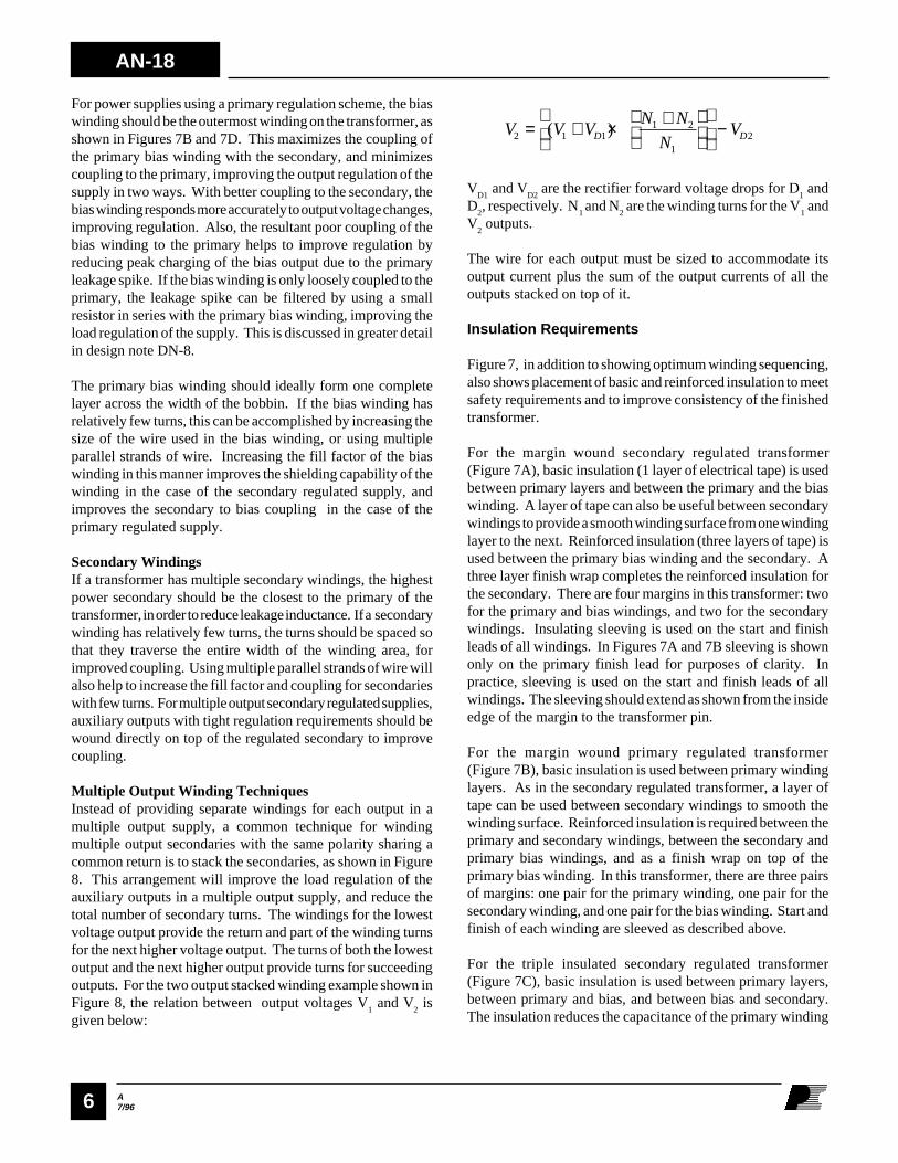
Multiple Output Winding TechniquesInstead of providing separate windings for each output in amultiple output supply, a common technique for windingmultiple output secondaries with the same polarity sharing acommon return is to stack the secondaries, as shown in Figure8. This arrangement will improve the load regulation of theauxiliary outputs in a multiple output supply, and reduce thetotal number of secondary turns. The windings for the lowestvoltage output provide the return and part of the winding turnsfor the next higher voltage output. The turns of both the lowestoutput and the next higher output provide turns for succeedingoutputs. For the two output stacked winding example shown inFigure 8, the relation between output voltages V
1 and V
2 is
given below:
V V VN N
NVD D2 1 1
1 2
12= + × +
−( )
VD1
and VD2
are the rectifier forward voltage drops for D1 and
D2, respectively. N
1 and N
2 are the winding turns for the V
1 and
V2 outputs.
The wire for each output must be sized to accommodate itsoutput current plus the sum of the output currents of all theoutputs stacked on top of it.
Insulation Requirements
Figure 7, in addition to showing optimum winding sequencing,also shows placement of basic and reinforced insulation to meetsafety requirements and to improve consistency of the finishedtransformer.
For the margin wound secondary regulated transformer(Figure 7A), basic insulation (1 layer of electrical tape) is usedbetween primary layers and between the primary and the biaswinding. A layer of tape can also be useful between secondarywindings to provide a smooth winding surface from one windinglayer to the next. Reinforced insulation (three layers of tape) isused between the primary bias winding and the secondary. Athree layer finish wrap completes the reinforced insulation forthe secondary. There are four margins in this transformer: twofor the primary and bias windings, and two for the secondarywindings. Insulating sleeving is used on the start and finishleads of all windings. In Figures 7A and 7B sleeving is shownonly on the primary finish lead for purposes of clarity. Inpractice, sleeving is used on the start and finish leads of allwindings. The sleeving should extend as shown from the insideedge of the margin to the transformer pin.
For the margin wound primary regulated transformer(Figure 7B), basic insulation is used between primary windinglayers. As in the secondary regulated transformer, a layer oftape can be used between secondary windings to smooth thewinding surface. Reinforced insulation is required between theprimary and secondary windings, between the secondary andprimary bias windings, and as a finish wrap on top of theprimary bias winding. In this transformer, there are three pairsof margins: one pair for the primary winding, one pair for thesecondary winding, and one pair for the bias winding. Start andfinish of each winding are sleeved as described above.
For the triple insulated secondary regulated transformer(Figure 7C), basic insulation is used between primary layers,between primary and bias, and between bias and secondary.The insulation reduces the capacitance of the primary winding

A7/96
AN-18
7
coupling and lowest leakage. For higher power applications(40 watts and above), a split primary “sandwich” constructionis recommended to minimize leakage inductance. Using a splitprimary will in general cut the leakage inductance to half that ofa transformer with a single primary winding. Split primaryconstruction for secondary regulated transformers is shown forthe margin wound and triple insulated case in Figures 10A and10B. A split winding construction is not recommended forprimary regulated designs, as it will result in poor load regulation.
High power secondary windings consisting of only a few turnsshould be spaced across the width of the bobbin window insteadof being bunched together, in order to maximize coupling to theprimary. Using multiple parallel strands of wire is an additionaltechnique of increasing the fill factor and coupling of a windingwith few turns. In such cases, the wire size may be determinedmore by the requirement for a good fill factor rather than theRMS current rating of the wire. Where cost permits, using foilwindings is also a good way of increasing coupling, althoughthis method is usually practical only for low voltage, highcurrent secondary windings.
and smooths the surface between windings. The finish wrap ofthree layers is more for cosmetic reasons than for safety. Thereare no margins and no sleeving.
In the triple insulated primary regulated transformer(Figure 7D), basic insulation is used between primary layers,between primary and secondary, and between secondary andbias. A three layer outer wrap is required on the outside forreinforced insulation. Again, no margins or sleeving arerequired.
Reducing Leakage Inductance
The winding order in a transformer has a large effect on theleakage inductance. Transformer windings should be arrangedin concentric fashion for minimum leakage inductance. Offsetor split bobbin construction (shown in Figure 9) should beavoided, as these techniques will result in high leakage inductanceand unacceptable primary clamp circuit dissipation.
In a multiple output transformer, the secondary with the highestoutput power should be placed closest to the primary for the best
Figure 8. Stacked Secondary Windings for Multiple Outputs.
PI-1798-030896
COMMON RETURN
V+
NP
D2
D1
I2
N2
N1TOPSwitch
Drain
I1
I2
I1+I2
V2
V1

AN-18
A7/968
PRIMARY FINISH LEAD (WITH SLEEVING)
REINFORCED INSULATION
BASIC INSULATION
PIN
MARGIN (6x)
PI-1803-030896
SECONDARY
PRIMARY SECOND 1/2 FINISHPRIMARY SECOND 1/2 START
SLEEVING
PRIMARY BIAS
PRIMARY FIRST 1/2 FINISH
PRIMARY FIRST 1/2 START
Figure 10A. Margin Wound Secondary Regulated Transformer with Split Primary.
PRIMARY FINISH LEAD (WITHOUT SLEEVING)
REINFORCED INSULATION
BASIC INSULATION
PIN
PI-1804-030896
TRIPLE INSULATED SECONDARY
PRIMARY SECOND 1/2 FINISH
PRIMARY SECOND 1/2 START
PRIMARY BIAS
PRIMARY FIRST 1/2 FINISHPRIMARY FIRST 1/2 START
Figure 10B. Triple Insulated Secondary Regulated Transformer with Split Primary.
PI-1829-041696
SECONDARY
BIAS
PRIMARY
BIAS
PRIMARY
MARGIN
MARGIN
SECONDARY
OFFSET WINDING CONSTRUCTION(NOT RECOMMENDED)
SPLIT BOBBIN CONSTRUCTION(NOT RECOMMENDED)
Figure 9. Offset and Split Bobbin Construction Techniques (Not Recommended).
EMI Reduction Techniques
The following transformer construction techniques help toreduce EMI:
• Make the primary winding the innermost winding on the bobbin.
• The start of the primary winding should be connected to the TOPSwitch drain.
• For a secondary regulated transformer design, place the bias winding between primary and secondary to act as a shield.
Additional EMI/RFI reduction techniques include shieldingbetween primary and secondary windings, and the addition ofa “flux band” to reduce the stray field around the transformer.
Shields are placed between the primary and secondary of atransformer to reduce the capacitive coupling of common mode
noise between primary and secondary. The shield can bereferenced either to the primary high voltage supply or to theprimary return. Typical shielded transformer constructions areshown in Figure 11. The most economical form of shield is awire shield. This type of shield can be added to the transformerwith very few extra steps, since it consists of a windingtraversing the full width of the bobbin. One end of the shieldwinding is terminated to the primary return or primary V+supply, while the other end of the winding is left floating,insulated with tape, and buried inside the transformer instead ofbeing terminated to a pin. The wire size used for a wire shieldis a compromise between a large size to minimize the numberof shield turns, and a relatively small wire size for ease oftermination. 24-27 AWG wire is a reasonable compromise forsmall to medium size transformers.
In some cases, the stray magnetic field around a switchingpower supply transformer can interfere with adjacent circuitryand contribute to EMI. To reduce this stray field, a copper “flux

A7/96
AN-18
9
Figure 11. Transformer Shield Placement.
SECONDARY
Insulated Wire Transformer Margin Wound Transformer
TAPE SHIELD BIAS
TRANSFORMER SHIELD PLACEMENT
SECONDARY
MARGINS
BIASSHIELD
PRIMARY
PI-1814-032796
PRIMARY
PI-1648-111695
COPPER FOIL
STRAP
Figure 12. Transformer Flux Band.
the information required to specify a transformer can be readdirectly from the completed spreadsheet. Other parametersmust be calculated using numbers from the spreadsheet andinformation from other sources, such as a wire table. Thespreadsheet parameters listed below provide information usedto specify a transformer. The number in parentheses indicatesthe cell location in the spreadsheet.
• Core Type (B23)• Bobbin Physical Winding Width (BW) (B27)• Safety Margin Width (M) (B28)• Number of Primary Layers (L) (B29)• Number of Secondary Turns (NS) (B30)• Primary Inductance (LP) (D44)• Primary Number of Turns (NP) (D45)
band” can be added around the outside of the transformer, asshown in Figure 12. The “flux band” acts as a shorted turn forstray flux outside the magnetic circuit formed by the transformerwindings and core. Opposing currents are induced in the fluxband by the stray fields, partially canceling their influence. Ifnecessary, the flux band can also be connected to primary returnto help reduce electrostatically coupled interference. If a fluxband is used, care must be taken to make sure that there issufficient total creepage distance from the primary pins to thesecondary pins through the flux band. Refer to AN-15 for moreinformation on EMI reduction techniques.
Transformer ConstructionTwo transformer design and construction examples are shownin Appendix B for margin wound and triple insulatedtransformers for use with TOPSwitch. The design procedure forthe two examples utilizes computer spreadsheet techniquesdescribed in application notes AN-16 and AN-17. The detailedstep-by-step flyback power supply design procedure for usingthe spreadsheet is shown in AN-16, while the spreadsheet itselfis described in detail in AN-17. The paragraphs below describethe procedures needed to apply the information generated bythe power supply design spreadsheet to a practical transformerdesign. These procedures are used to complete the two designexamples in Appendix B. In this application note, two completedspreadsheet design examples are presented. Information derivedfrom these spreadsheets is used in the construction examples.
Spreadsheet Parameters Used forTransformer SpecificationOnce a power supply design spreadsheet has been completedand optimized, information from the spreadsheet can be used tocomplete a specification for transformer construction. Much of
AN-18
A7/9610
• Bias Winding Turns (NB) (D46)
• Gapped Core Inductance Coefficient (ALG
) (C47)• Primary Wire Gauge (AWG ) (D56)• Primary Winding Current Capacity (CMA) (D58)• Secondary Circular Mils (CMS) (C66)• Secondary RMS Current (I
SRMS) (D62)
• Secondary Wire Gauge (AWGS) (D67)
Transformer Construction StepsOnce the transformer parameters have been determined from aspreadsheet design, the following steps are required to determinethe remaining information needed for transformer construction:
• Calculate and select wire sizes using spreadsheetinformation and wire table
• Pick transformer construction style• Determine insulating tape sizes• Determine insulating sleeving size• Choose method of core gapping
Wire Sizes
Wire sizes for the primary, secondary, and bias windings aredetermined from the information provided by the power supplydesign spreadsheet. Some extra steps may be necessary todetermine the wire size for a given winding. The wire sizeselection process is described below.
Primary Wire SizeThe power supply design spreadsheet calculates the insulatedwire diameter for the primary based on the number of primaryturns, the number of winding layers, and the available windingspace on the bobbin. The calculated maximum insulated wirediameter is shown in cell (D53) of the spreadsheet. Thespreadsheet uses this value to choose an AWG wire size thatcomes closest to fitting the bobbin. If the wire size falls betweentwo standard AWG wire gauges, the spreadsheet willautomatically round down the primary wire size to the nextsmaller wire gauge. The resulting primary AWG wire size isdisplayed in cell (D56) of the spreadsheet. The spreadsheetcalculates the current capacity of the primary wire (CMA) incircular mils per ampere and displays the result in cell (D58).The CMA value should be between 200 to 500 circular mils perampere for a practical design. If the CMA is not within theselimits, the design should be adjusted to bring the primary CMAwithin limits.
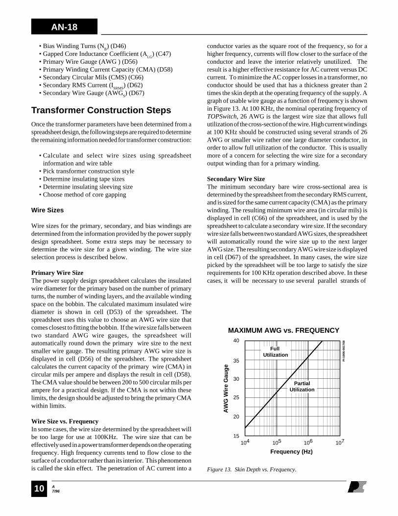
Wire Size vs. FrequencyIn some cases, the wire size determined by the spreadsheet willbe too large for use at 100KHz. The wire size that can beeffectively used in a power transformer depends on the operatingfrequency. High frequency currents tend to flow close to thesurface of a conductor rather than its interior. This phenomenonis called the skin effect. The penetration of AC current into a
conductor varies as the square root of the frequency, so for ahigher frequency, currents will flow closer to the surface of theconductor and leave the interior relatively unutilized. Theresult is a higher effective resistance for AC current versus DCcurrent. To minimize the AC copper losses in a transformer, noconductor should be used that has a thickness greater than 2times the skin depth at the operating frequency of the supply. Agraph of usable wire gauge as a function of frequency is shownin Figure 13. At 100 KHz, the nominal operating frequency ofTOPSwitch, 26 AWG is the largest wire size that allows fullutilization of the cross-section of the wire. High current windingsat 100 KHz should be constructed using several strands of 26AWG or smaller wire rather one large diameter conductor, inorder to allow full utilization of the conductor. This is usuallymore of a concern for selecting the wire size for a secondaryoutput winding than for a primary winding.
Secondary Wire SizeThe minimum secondary bare wire cross-sectional area isdetermined by the spreadsheet from the secondary RMS current,and is sized for the same current capacity (CMA) as the primarywinding. The resulting minimum wire area (in circular mils) isdisplayed in cell (C66) of the spreadsheet, and is used by thespreadsheet to calculate a secondary wire size. If the secondarywire size falls between two standard AWG sizes, the spreadsheetwill automatically round the wire size up to the next largerAWG size. The resulting secondary AWG wire size is displayedin cell (D67) of the spreadsheet. In many cases, the wire sizepicked by the spreadsheet will be too large to satisfy the sizerequirements for 100 KHz operation described above. In thesecases, it will be necessary to use several parallel strands of
Figure 13. Skin Depth vs. Frequency.
40
20
15104 105 106 107
Frequency (Hz)
AW
G W
ire
Gau
ge
MAXIMUM AWG vs. FREQUENCY
25
30
PI-
1906
-061
768
35
Partial Utilization
Full Utilization

A7/96
AN-18
11
26 AWG or smaller wire to construct a secondary winding thatsatisfies both the CM
S requirement and the 100KHz maximum
wire size requirement. The total bare area of the paralleledsecondary conductors should be close to the CM
S value calculated
by the spreadsheet in cell (C66). If the total bare area is greaterthan or equal to the calculated value, the wire size for theparalleled secondary winding can be used without furtherchecking. If the total bare area is less than the calculated valuefrom cell (C66), the current capacity should be checked to makesure that it remains within the design limits. The currentcapacity of the paralleled wires can be calculated from theformula:
CMAN CM
ISSRMS
= ×
CMAS is the current capacity of the parallel secondary winding
in circular mils per ampere, N is the number of strands in thesecondary winding, CM
is the bare area of a single secondary
conductor in circular mils (from the wire table in Appendix A),and I
SRMS is the secondary RMS current from cell (D62) of the
spreadsheet.
Bias Winding DesignThe wire size for the bias winding will be determined mainly byspace-filling considerations rather than current capacity, asdescribed in the previous sections on transformer construction.The wire size of the bias winding should be selected to form ascomplete a layer as possible. Usually, it will be necessary to usea parallel bifilar winding in order to fill the largest possiblespace with a manageable wire size. In the Appendix A wiretable, turns per centimeter (TC) values are given for AWG wiresizes. This data can be used to select a bias winding wire size fora bifilar winding for a given number of turns and availablebobbin width. The required TC value can be calculated from theequation:
TCN
BW MB= × ×
− ×2 10
2( )
TC is the turns per centimeter capability of the bias winding. N
B
is the number of bias turns from cell (D46) of the spreadsheet,BW is the bobbin physical winding width in mm from cell (B27)of the spreadsheet, and M is the margin width in mm from cell(B28). Once the required TC
is calculated, a wire size is
selected from the Appendix A wire table with a TC greater thanor equal to the calculated value. The largest recommended wiresize is 24 AWG, for ease of winding and termination. If the wiresize used does not form one complete layer, the winding turnsshould be wound evenly across the width of the bobbin windingarea.
Choosing a Transformer Construction Type
The transformer construction types shown in Figures 7 and 10are optimized for margin wound and triple insulated wiretransformer designs for both secondary and primary regulatedpower supply designs. These construction types are suitable forthe majority of TOPSwitch flyback supply applications. Thesefigures should be used as examples for specifying the order ofthe transformer windings and the placement of the margins andinsulating sleeving (if used), and insulating tape. Theconstruction type is chosen on the basis of the supply regulationscheme (primary or secondary) and insulation type (marginwound or triple insulated wire). Applications requiring thelowest transformer cost but not the smallest possible transformersize can use a margin wound transformer. Applications requiringthe smallest possible transformer size should use a triple insulatedwire design.
The construction types shown in Figure 10 are low-leakage splitprimary designs, and should be used if the output power of thesupply is greater than 40W. These designs can also be used toincrease efficiency for a lower power supply, but will be highercost than a design with a one piece primary winding.
Choosing Insulation Tape Width
For a margin wound transformer construction, three differentinsulation tape widths are required. A tape width equal to thewidth of the bobbin from flange to flange (BW) is required forreinforced insulation. This information can be read directlyfrom cell (B27) of the spreadsheet. A tape width equal to thewidth of the bobbin minus the width of the margins is needed forbasic insulation between winding layers and adjacent primaryor secondary windings. This width can be calculated with theequation:
W BW MTB = − ×( )2
WTB is the width of the basic insulation tape, BW is the width ofthe bobbin from cell (B27) of the spreadsheet, and M is themargin width from cell (B28). The third tape width required isfor the margin layers on each side of the bobbin. The width ofthis tape is picked to satisfy applicable safety regulations andentered in cell (B28). Triple insulated wire transformers requireone size of tape for basic insulation, with a width equal to BW.
Insulating Sleeving
In margin wound transformer designs, insulating sleeving isrequired on all winding start and finish leads, so that the primaryto secondary isolation provided by the margins is preserved.The sleeving should have a wall thickness of at least 0.4 mm.Sleeving for this purpose can be obtained in sizes equivalent toAWG wire sizes. Usually one size of sleeving, equal to the

AN-18
A7/9612
largest wire size, is sufficient for a transformer design. This sizeof sleeving can then be used for all other wire sizes in thetransformer. Sleeving is not required for triple insulated wiredesigns.
Transformer Gapping , Primary Inductance Tolerance
In standard practice, transformer cores for flyback transformerapplications are gapped to a specified value of A
LG rather than
a precise gap length. The center value of ALG
can be read fromcell (C47) of the spreadsheet. A
LG is customarily specified to a
tolerance of +/- 5-6%. The gap length shown in cell (D 51) ofthe spreadsheet is useful mainly for checking transformer peakflux density and for determining the practicality of the design,and should not be used in a transformer specification.Transformer gaps smaller than 0.051 mm (0.002 in) should beavoided, as it is difficult to maintain tolerance on this small agap. Transformer primary inductance tolerance should bespecified at +/- 10% to +/- 15%. Tighter tolerances offer noperformance advantages, and can be unnecessarily costly.
For high volume transformer applications, the transformer coreis commonly gapped by grinding down the center leg of one ofthe ferrite core halves to introduce a single air gap in themagnetic path of the core. An alternate technique for smallproduction runs and prototypes is to use non-conducting spacersbetween the core halves. If spacers are chosen rather thangrinding the core center leg, the spacer thickness should be halfthe value used for the center leg gap, as the magnetic path isdivided twice by the spacers: once at the core center leg, andonce at the core outer legs.
Completion of Transformer Specification
Once the above information has been determined, there issufficient information to complete a specification forconstruction of the transformer. The specification should containthe following information:
• Transformer schematic, showing all windings, order of windings, pin assignments, dots indicating winding starts, turns of each winding, and wire types and sizes
• Transformer parts list, including:
Core part number and ALG
Bobbin part numberAll wire types and sizes usedAll insulating tape types and widthsInsulating sleeving type and size (if used)Varnish type (if used)
• Transformer specifications:
Primary inductance and tolerancePrimary leakage inductance and tolerance (determinedfrom prototype)Applicable safety standards, or hipot test voltage andminimum creepage distances
• Detailed construction drawing and instructions (optional)
Design Summary1) Load Design Spreadsheet with Application Variables and
TOPSwitch Variables per instructions in AN-16.
2) Choose a core from Appendix A, and determine core and bobbin parameters needed for spreadsheet from manufacturer’s catalog data. Load these values into the spreadsheet.
3) Complete spreadsheet per AN-16 procedure and iterate until all parameters meet recommended design limits.
4) From spreadsheet values and Appendix A wire table, calculate primary, secondary, and bias wire sizes.
5) Pick a transformer construction style depending on supply regulation scheme (primary or secondary) and insulation type (margin wound or triple insulated).
6) Calculate tape widths needed for transformer insulation.
7) Pick insulation sleeving size (if necessary).
8) Complete transformer specification using spreadsheet values and information from steps 4-7.

A7/96
AN-18
13
Appendix AAppendix A contains a wire table (Table 1) and a table ofsuggested core sizes (Table 2) for use in the flyback transformerdesign and construction procedures described in this document.Also included is a list of manufacturers for transformerconstruction materials. Electrical and mechanical data on the
cores listed in Table 2 can be obtained from the ferrite coremanufacturers listed in this appendix. These manufacturersalso carry a selection of bobbins for their more popular coresizes. Additional sources for transformer bobbins are also listedin this appendix.
Turns/Inch
23.2
25.9
28.9
32.4
36.2
40.2
44.8
50.3
56.2
62.1
69.4
76.9
86.2
95.2
105.3
117.7
133.3
149.3
166.7
181.8
204.1
232.6
263.2
294.1
333.3
370.4
400.0
Turns/cm
9.13
10.19
11.37
12.75
14.25
15.82
17.63
19.80
22.12
24.44
27.32
30.27
33.93
37.48
41.45
46.33
52.48
58.77
65.62
71.57
80.35
91.57
103.6
115.7
131.2
145.8
157.4
AWG
Wire
Size
18
19
20
21
22
23
24
25
26
27
28
29
30
31
32
33
34
35
36
37
38
39
40
41
42
43
44
SWG
Wire
Size
19
20
21
22
23
24
28
29
30
33
39
41
42
43
44
45
46
Metric
Size
(mm)
1.00
0.900
0.800
0.750
0.700
0.600
0.550
0.450
0.400
0.350
0.320
0.280
0.250
0.220
0.200
0.180
0.160
0.140
0.130
0.110
0.100
0.090
0.080
0.070
0.060
cm 210-3
8.228
6.531
5.188
4.116
3.243
2.588
2.047
1.623
1.280
1.021
0.8046
0.6470
0.5067
0.4013
0.3242
0.2554
0.2011
0.1589
0.1266
0.1026
0.08107
0.06207
0.04869
0.03972
0.03166
0.02452
0.0202
Table 1 Wire Table.
CIR-MIL
1624
1289
1024
812.3
640.1
510.8
404.0
320.4
252.8
201.6
158.8
127.7
100.0
79.21
64.00
50.41
39.69
31.36
25.00
20.25
16.00
12.25
9.61
7.84
6.25
4.84
4.00
Bare Wire Cross-SectionalArea (CM)
TC
AN-18
A7/9614
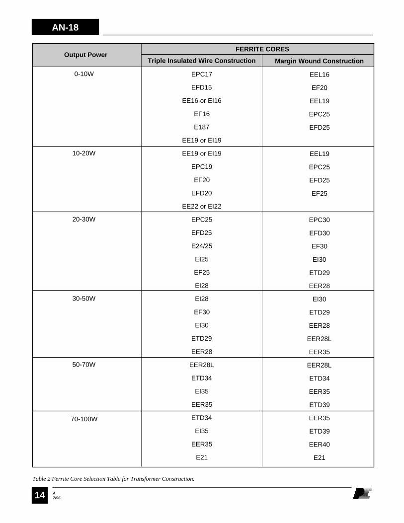
0-10W
10-20W
20-30W
30-50W
50-70W
70-100W
Table 2 Ferrite Core Selection Table for Transformer Construction.
Margin Wound Construction
EEL16
EF20
EEL19
EPC25
EFD25
EEL19
EPC25
EFD25
EF25
EPC30
EFD30
EF30
EI30
ETD29
EER28
EI30
ETD29
EER28
EER28L
EER35
EER28L
ETD34
EER35
ETD39
EER35
ETD39
EER40
E21
Triple Insulated Wire Construction
EPC17
EFD15
EE16 or EI16
EF16
E187
EE19 or EI19
EE19 or EI19
EPC19
EF20
EFD20
EE22 or EI22
EPC25
EFD25
E24/25
EI25
EF25
EI28
EI28
EF30
EI30
ETD29
EER28
EER28L
ETD34
EI35
EER35
ETD34
EI35
EER35
E21
FERRITE CORESOutput Power
A7/96
AN-18
15
Transformer Material VendorsThe contact numbers below are listed for information purposesonly. Please refer to local authorized representatives anddistributors for pricing and ordering information.
Ferrite Cores
TDK Corporation, of America, 1600 Feehanville Dr. MountProspect IL 60056 (847) 803-6100 (847) 803-6296 (FAX)
Siemens Matsushita Components, Special Products Division,186 Wood Ave, South Iselin, NJ 08830 (908) 906-4300 (908) 632-2830 (FAX)
Philips Components, Discrete Products Division, MagneticProducts, 1033 Kings Highway, Saugerties, NY 12477(914) 246-2811 (914) 246-0486 (FAX)
Tokin America, Inc.,155 Nicholson Lane, San Jose, CA 95134(408) 432-8020 (408) 434-0375 (FAX)
Thomson Passive Components Corporation, 2211-HDistribution Center Drive, Charlotte, NC 28269(704) 597-0766 (704) 597-0553 (FAX)
Bobbins
Many of the ferrite core vendors above offer compatible bobbinsfor their cores. Additional bobbin suppliers are listed below:
Yih Hwa Enterprises Co., Ltd., 2 Floor, No. 2, Alley 4, Lane222 Lien Cheng Rd. Chung Ho City, Taipei, Taiwan, R.O.C.886-2-2483366 886-2-2406919 (FAX)
Taiwan Shu Lin Enterprise Co., Ltd., 760 Chung Cheng Road,Chung Ho City, Taipei Tsien, Taiwan, R.O.C. 886 2 2231500886 2 2224646 (FAX)
B&B Products Corp., 2190 Ironwood Crest Dr., Tucson, AZ85745 (520) 743-3389 (520) 743-8000 (FAX)
Miles-Platts, Inc. 901 Touhy Av., Elk Grove Village, IL 60007(847) 364-0363 (847) 364-0614 (FAX)
Insulating Materials
3M Electrical Specialties Division, Bldg. 130-4N-40, 3M AustinCenter, P.O. Box 2963, Austin TX 78769 (800) 364-3577(800) 713-6329
CHR/Furon, 407 East St., P.O. Box 1911, New Haven, CT06509 (203) 777-3631 (203) 787-1725 (FAX)
EIS, 41444 Christy Street, Fremont, CA 94538 (510) 490-5855(510) 490-2956 (FAX)
Tesa Tape Inc. 5825 Carnegie Bl., Charlotte, NC 28209(704) 554-0707 (800) 852-8831 (FAX)
Magnet Wire
Belden Wire and Cable Company, P.O. Box 1980, Richmond,IN 47375 (317) 983-5200 (317) 983-5656 (FAX)
MWS Wire Industries 31200 Cedar Valley Dr., WestlakeVillage, CA 90404 (818) 991-8553 (818) 706-0911 (FAX)
Phelps Dodge Magnet Wire, 2131 S. Coliseum Blvd. FortWayne, IN 46803 (219) 421-5400 (219) 421-5564 (FAX)
Rea Magnet Wire Co., Inc. 3600 E. Pontiac St. Fort Wayne, IN46896 (219) 424-4252 (219) 421-7349 (FAX)
Triple Insulated Wire
Furukawa Electric America, Inc. 200 Westpark Drive, Suite190, Peachtree City, GA 30269 (770) 487-1234(770) 487-9910 (FAX)
Furukawa Electric Co. Ltd. 6-1, Marunouchi 2-chome, Chiyoda-ku, Tokyo 100, Japan (PH) 81-3-3286-3226(FAX) 81-3-3286-3747
Rubudue Wire Company 5150 E. La Palma Av., Suite 108Anaheim Hills, CA 92807 (714) 693-5512(714) 693-5515 (FAX)
Belden Wire and Cable B.V., Edisonstraat 9, P.O. Box 9, NL5900 AA Venlo, Netherlands (PH) 31 773 878 442 (FAX) 31 773 878 448
Transformer Varnishes
John C. Dolph, Co. Box 267, Monmouth Junction, NJ 08852(908) 329-2333 (908) 329-1143 (FAX)
Schenectady Chemicals, Inc. Box 1046, Schenectady, NY12301 (518) 370-4200 (518) 382-8129 (FAX)
P.D. George, 9 Ohio River Boulevard, Sewickley, PA 15143(800) 999-5700 (412) 741-8892
Epoxylite Corp., 9400 Toledo Way, P.O. Box 19671, Irvine,CA 92713 (714) 951-3231 (714) 472-0980 (FAX)

AN-18
A7/9616
Figure 1. Typical TOPSwitch Power Supply for 12V, 15W Output.
PI-1809-031896
RTN
D2MBR360
D31N4148
R268 Ω
VR21N6001B
11 V
C3120 µF25 V
T1
D1UF4005
C2680 µF25 V
VR1P6KE200
BR1600 V
C147 µF400 V
R139 Ω
U2NEC2501-H
U1TOP201YAI
DRAIN
SOURCE
CONTROL
C40.1 µF
C71.0 nF
Y1
L13.3 µH
F13.15 A
J1
C60.1 µF
X2
L222 mH
L
N
1
9,10
26,7
5
4
C547 µF10 V
VIN = 85-265 VAC 50/60 Hz
VB = 12 VIB = 10 mA
VO = 12 V
PO = 15 W
Appendix B
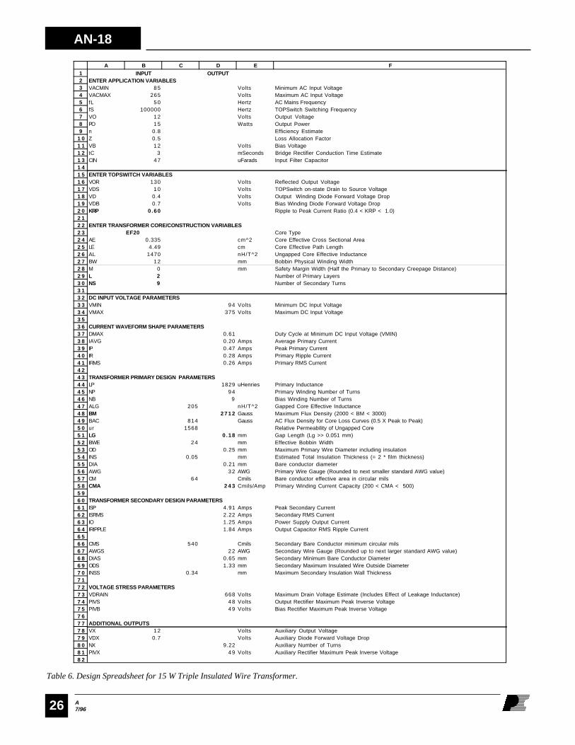
Transformer Construction ExamplesTwo transformer design and construction examples using marginwound and triple insulated wire construction techniques aredescribed below. These designs are based on the 12V, 15Wuniversal input power supply shown in Figure 1. The designprocedure for the two examples utilizes computer spreadsheettechniques described in application notes AN-16 and AN-17.The detailed step-by-step flyback power supply design procedurefor using the spreadsheet is shown in AN-16. Two completedspreadsheet design examples are shown in this appendix(Table 1 and Table 6). Information derived from thesespreadsheets is used in the construction examples.
Spreadsheet Input Parameters
Two power supply design spreadsheets are shown in Tables 1and 6. Table 1 details a power supply design utilizing a marginwound transformer with an EF25 core. Table 6 shows a designfor the same power supply utilizing a triple insulated wire
transformer with an EF20 core. The power supply design shownin Figure 1 was used as a starting point for both transformerdesign/construction examples. Target specifications for thispower supply design are shown in Table 2. Specifications andselected component values from Table 2 are loaded into theapplication variables section of the spreadsheets. Table 3 showsTOPSwitch and output rectifier operating conditions used in theTOPSwitch variable section of the spreadsheets. Since both ofthe transformer designs are for the same power supply, thevalues loaded into the application variables section andTOPSwitch variable section for both spreadsheets are exactlythe same, with the exception of the value used for reflectedoutput voltage (V
OR, cell B16). For the triple insulated wire
transformer design shown in Table 6, VOR
is adjusted to a valueslightly lower than the default value recommended in AN-16 inorder to reduce the number of primary turns. This is discussedin the paragraphs devoted to the triple insulated wire designexample.
The transformer construction variables in the design spreadsheetare determined by the core, bobbin and transformer constructiontype, and are therefore different for the two design examples.
A7/96
AN-18
17
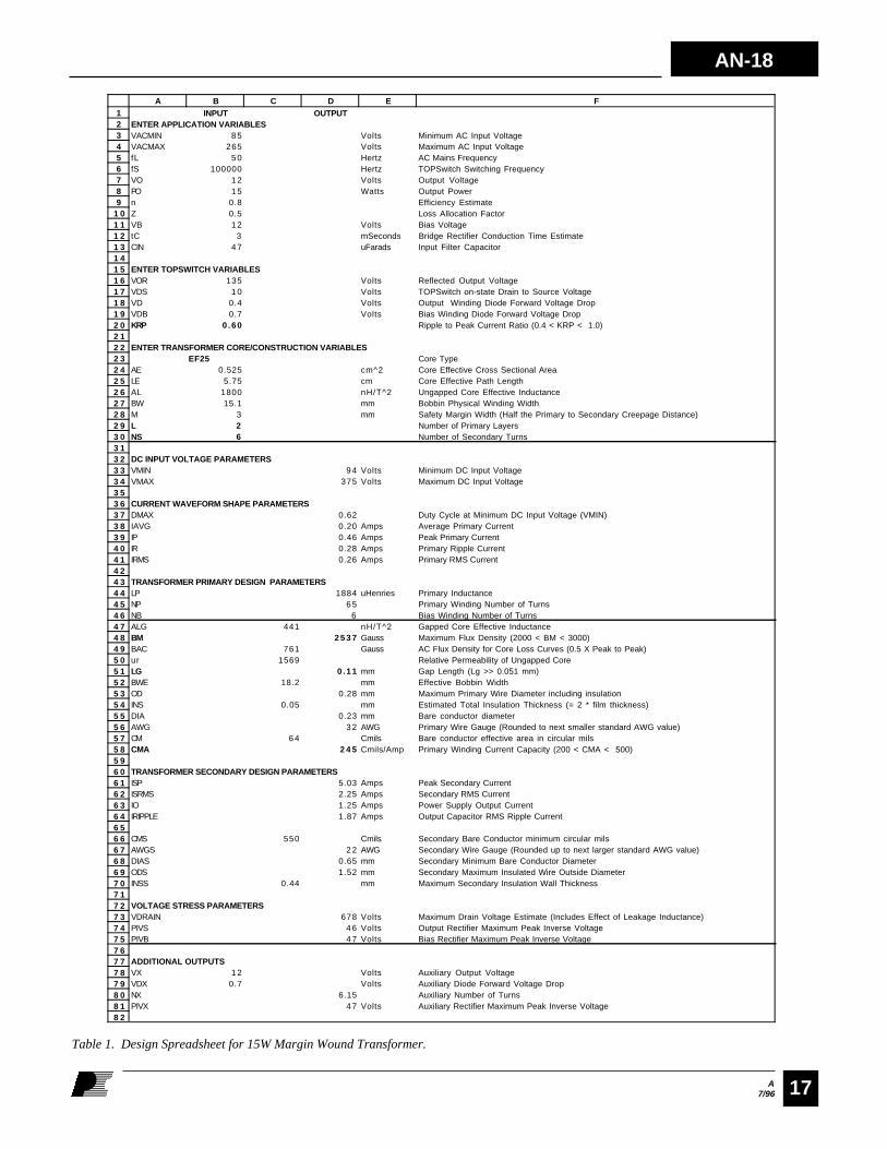
Table 1. Design Spreadsheet for 15W Margin Wound Transformer.
123456789
1 01 11 21 31 41 51 61 71 81 92 02 12 22 32 42 52 62 72 82 93 03 13 23 33 43 53 63 73 83 94 04 14 24 34 44 54 64 74 84 95 05 15 25 35 45 55 65 75 85 96 06 16 26 36 46 56 66 76 86 97 07 17 27 37 47 57 67 77 87 98 08 18 2
A B C D E F INPUT OUTPUTENTER APPLICATION VARIABLESVACMIN 8 5 Volts Minimum AC Input VoltageVACMAX 265 Volts Maximum AC Input VoltagefL 5 0 Hertz AC Mains FrequencyfS 100000 Hertz TOPSwitch Switching FrequencyVO 1 2 Volts Output VoltagePO 1 5 Watts Output Powern 0.8 Efficiency EstimateZ 0.5 Loss Allocation Factor VB 1 2 Volts Bias VoltagetC 3 mSeconds Bridge Rectifier Conduction Time EstimateCIN 4 7 uFarads Input Filter Capacitor
ENTER TOPSWITCH VARIABLESVOR 135 Volts Reflected Output VoltageVDS 1 0 Volts TOPSwitch on-state Drain to Source Voltage VD 0.4 Volts Output Winding Diode Forward Voltage DropVDB 0.7 Volts Bias Winding Diode Forward Voltage DropKRP 0.60 Ripple to Peak Current Ratio (0.4 < KRP < 1.0)
ENTER TRANSFORMER CORE/CONSTRUCTION VARIABLESEF25 Core Type
AE 0.525 cm^2 Core Effective Cross Sectional AreaLE 5.75 cm Core Effective Path LengthAL 1800 nH/T^2 Ungapped Core Effective InductanceBW 15.1 mm Bobbin Physical Winding WidthM 3 mm Safety Margin Width (Half the Primary to Secondary Creepage Distance)L 2 Number of Primary LayersNS 6 Number of Secondary Turns
DC INPUT VOLTAGE PARAMETERSVMIN 9 4 Volts Minimum DC Input VoltageVMAX 375 Volts Maximum DC Input Voltage
CURRENT WAVEFORM SHAPE PARAMETERSDMAX 0.62 Duty Cycle at Minimum DC Input Voltage (VMIN)IAVG 0.20 Amps Average Primary CurrentIP 0.46 Amps Peak Primary CurrentIR 0.28 Amps Primary Ripple CurrentIRMS 0.26 Amps Primary RMS Current
TRANSFORMER PRIMARY DESIGN PARAMETERSLP 1884 uHenries Primary InductanceNP 6 5 Primary Winding Number of TurnsNB 6 Bias Winding Number of TurnsALG 441 nH/T^2 Gapped Core Effective InductanceBM 2 5 3 7 Gauss Maximum Flux Density (2000 < BM < 3000)BAC 761 Gauss AC Flux Density for Core Loss Curves (0.5 X Peak to Peak)ur 1569 Relative Permeability of Ungapped CoreLG 0.11 mm Gap Length (Lg >> 0.051 mm)BWE 18.2 mm Effective Bobbin WidthOD 0.28 mm Maximum Primary Wire Diameter including insulationINS 0.05 mm Estimated Total Insulation Thickness (= 2 * film thickness)DIA 0.23 mm Bare conductor diameterAWG 3 2 AWG Primary Wire Gauge (Rounded to next smaller standard AWG value)CM 6 4 Cmils Bare conductor effective area in circular milsCMA 2 4 5 Cmils/Amp Primary Winding Current Capacity (200 < CMA < 500)
TRANSFORMER SECONDARY DESIGN PARAMETERSISP 5.03 Amps Peak Secondary CurrentISRMS 2.25 Amps Secondary RMS CurrentIO 1.25 Amps Power Supply Output CurrentIRIPPLE 1.87 Amps Output Capacitor RMS Ripple Current
CMS 550 Cmils Secondary Bare Conductor minimum circular milsAWGS 2 2 AWG Secondary Wire Gauge (Rounded up to next larger standard AWG value)DIAS 0.65 mm Secondary Minimum Bare Conductor DiameterODS 1.52 mm Secondary Maximum Insulated Wire Outside DiameterINSS 0.44 mm Maximum Secondary Insulation Wall Thickness
VOLTAGE STRESS PARAMETERSVDRAIN 678 Volts Maximum Drain Voltage Estimate (Includes Effect of Leakage Inductance)PIVS 4 6 Volts Output Rectifier Maximum Peak Inverse VoltagePIVB 4 7 Volts Bias Rectifier Maximum Peak Inverse Voltage
ADDITIONAL OUTPUTSVX 1 2 Volts Auxiliary Output VoltageVDX 0.7 Volts Auxiliary Diode Forward Voltage DropNX 6.15 Auxiliary Number of TurnsPIVX 4 7 Volts Auxiliary Rectifier Maximum Peak Inverse Voltage
AN-18
A7/9618
DESCRIPTION
Minimum AC Input Voltage
Maximum AC Input Voltage
AC Mains Frequency
TOPSwitch Switching Frequency
Output Voltage
Output Power
Estimated Efficiency
Loss Allocation Factor
Bias Voltage
Bridge RectifierConduction Time Estimate
Input Filter Capacitor (C1)
CELL #
B3
B4
B5
B6
B7
B8
B9
B10
B11
B12
B13
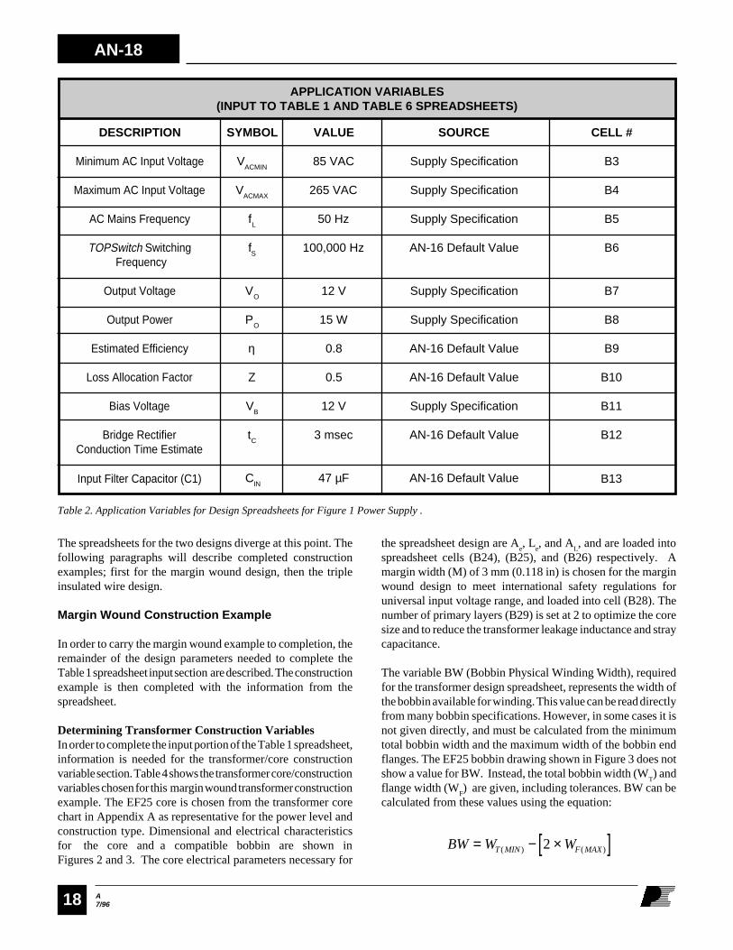
APPLICATION VARIABLES(INPUT TO TABLE 1 AND TABLE 6 SPREADSHEETS)
SYMBOL
VACMIN
VACMAX
fL
fS
VO
PO
η
Z
VB
tC
C
IN
VALUE
85 VAC
265 VAC
50 Hz
100,000 Hz
12 V
15 W
0.8
0.5
12 V
3 msec
47 µF
SOURCE
Supply Specification
Supply Specification
Supply Specification
AN-16 Default Value
Supply Specification
Supply Specification
AN-16 Default Value
AN-16 Default Value
Supply Specification
AN-16 Default Value
AN-16 Default Value
Table 2. Application Variables for Design Spreadsheets for Figure 1 Power Supply .
The spreadsheets for the two designs diverge at this point. Thefollowing paragraphs will describe completed constructionexamples; first for the margin wound design, then the tripleinsulated wire design.
Margin Wound Construction Example
In order to carry the margin wound example to completion, theremainder of the design parameters needed to complete theTable 1 spreadsheet input section are described. The constructionexample is then completed with the information from thespreadsheet.
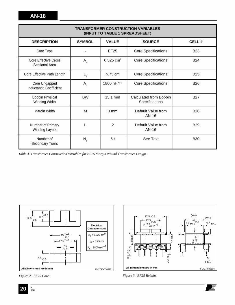
Determining Transformer Construction VariablesIn order to complete the input portion of the Table 1 spreadsheet,information is needed for the transformer/core constructionvariable section. Table 4 shows the transformer core/constructionvariables chosen for this margin wound transformer constructionexample. The EF25 core is chosen from the transformer corechart in Appendix A as representative for the power level andconstruction type. Dimensional and electrical characteristicsfor the core and a compatible bobbin are shown inFigures 2 and 3. The core electrical parameters necessary for
the spreadsheet design are Ae, L
e, and A
L, and are loaded into
spreadsheet cells (B24), (B25), and (B26) respectively. Amargin width (M) of 3 mm (0.118 in) is chosen for the marginwound design to meet international safety regulations foruniversal input voltage range, and loaded into cell (B28). Thenumber of primary layers (B29) is set at 2 to optimize the coresize and to reduce the transformer leakage inductance and straycapacitance.
The variable BW (Bobbin Physical Winding Width), requiredfor the transformer design spreadsheet, represents the width ofthe bobbin available for winding. This value can be read directlyfrom many bobbin specifications. However, in some cases it isnot given directly, and must be calculated from the minimumtotal bobbin width and the maximum width of the bobbin endflanges. The EF25 bobbin drawing shown in Figure 3 does notshow a value for BW. Instead, the total bobbin width (W
T) and
flange width (WF) are given, including tolerances. BW can be
calculated from these values using the equation:
BW W WT MIN F MAX= − ×[ ]( ) ( )2
A7/96
AN-18
19
DESCRIPTION
Reflected Output Voltage
TOPSwitch Drain to SourceVoltage with MOSFET on
Output Diode (D2)Forward Voltage Drop
Bias Diode (D3)Forward Voltage Drop
Primary Current Rippleto Peak Ratio
CELL #
B16
B17
B18
B19
B20
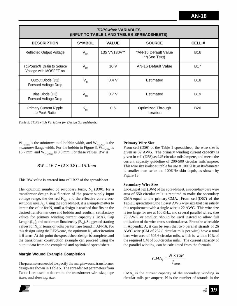
TOPSwitch VARIABLES(INPUT TO TABLE 1 AND TABLE 6 SPREADSHEETS)
SYMBOL
VOR
VDS
VD
VDB
KRP
VALUE
135 V*/130V**
10 V
0.4 V
0.7 V
0.6
SOURCE
*AN-16 Default Value**(See Text)
AN-16 Default Value
Estimated
Estimated
Optimized ThroughIteration
Primary Wire SizeFrom cell (D56) of the Table 1 spreadsheet, the wire size isgiven as 32 AWG. The primary winding current capacity isgiven in cell (D58) as 245 circular mils/ampere, and meets thecurrent capacity guideline of 200-500 circular mils/ampere.This wire size is also suitable for use at 100 KHz, as its diameteris smaller than twice the 100KHz skin depth, as shown byFigure 13.
Secondary Wire SizeLooking at cell (B66) of the spreadsheet, a secondary bare wirearea of 550 circular mils is required to make the secondaryCMA equal to the primary CMA. From cell (D67) of theTable 1 spreadsheet, the closest AWG wire size that can satisfythis requirement with a single wire is 22 AWG. This wire sizeis too large for use at 100KHz, and several parallel wires, size26 AWG or smaller, should be used instead to allow fullutilization of the wire cross-sectional area. From the wire tablein Appendix A, it can be seen that two parallel strands of 26AWG wire (CM of 252.8 circular mils per wire) have a totalbare wire area of 505.6 circular mils, which is within 10% ofthe required CM of 550 circular mils. The current capacity ofthe parallel winding can be calculated from the formula:
CMAN CM
ISSRMS
= ×
CMAS is the current capacity of the secondary winding in
circular mils per ampere, N is the number of strands in the
WT(MIN)
is the minimum total bobbin width, and WF(MAX)
is themaximum flange width. For the bobbin in Figure 3, W
T(MIN) is
16.7 mm and WF(MAX)
is 0.8 mm. For these values, BW is:
BW mm= − × =16 7 2 0 8 15 1. ( . ) .
This BW value is entered into cell B27 of the spreadsheet.
The optimum number of secondary turns, NS (B30), for a
transformer design is a function of the power supply inputvoltage range, the desired K
RP, and the effective core cross-
sectional area Ae. Using the spreadsheet, it is a simple matter to
iterate the value for NS until a design is reached that fits on the
desired transformer core and bobbin and results in satisfactoryvalues for primary winding current capacity (CMA), GapLength (L
G), and maximum flux density (B
M). Suggested starting
values for NS in terms of volts per turn are found in AN-16. For
this design using the EF25 core, the optimum NS after iteration
is 6 turns. At this point the spreadsheet design is complete, andthe transformer construction example can proceed using theoutput data from the completed and optimized spreadsheet.
Margin Wound Example Completion
The parameters needed to specify the margin wound transformerdesign are shown in Table 5. The spreadsheet parameters fromTable 1 are used to determine the transformer wire size, tapesizes, and sleeving size.
Table 3. TOPSwitch Variables for Design Spreadsheets.
AN-18
A7/9620
12.8 -0.5
7.5
7.5
-0.6
25 +0.8 -0.7
17.5+0.8
8.7 +0.5
Electrical Characteristics
Ae =0.525 cm2
le = 5.75 cm
AL= 1800 nH/T2
PI-1796-030896
-0.5
All Dimensions are in mm
Figure 2. EF25 Core.
27.5
17.8
max
3.5
-0.5
2.2
-0.1
9.4 -0
.25
7.7
+0.
2
-0.3
17.3-0.2517
-0.30.7 ±0.1 0.7
0.7
±0.17.7+0.15
PI-1797-030896All Dimensions are in mm
(WT)(WF)
Figure 3. EF25 Bobbin.
DESCRIPTION
Core Type
Core Effective CrossSectional Area
Core Effective Path Length
Core UngappedInductance Coefficient
Bobbin PhysicalWinding Width
Margin Width
Number of PrimaryWinding Layers
Number ofSecondary Turns
CELL #
B23
B24
B25
B26
B27
B28
B29
B30
TRANSFORMER CONSTRUCTION VARIABLES(INPUT TO TABLE 1 SPREADSHEET)
SYMBOL
-
Ae
Le
AL
BW
M
L
NS
VALUE
EF25
0.525 cm2
5.75 cm
1800 nH/T2
15.1 mm
3 mm
2
6 t
SOURCE
Core Specifications
Core Specifications
Core Specifications
Core Specifications
Calculated from BobbinSpecifications
Default Value fromAN-16
Default Value fromAN-16
See Text
Table 4. Transformer Construction Variables for EF25 Margin Wound Transformer Design.

A7/96
AN-18
21
DESCRIPTION
Core Type, Material
Bobbin Type
Number of Primary Turns
Number of Secondary Turns
Number of Bias Winding Turns
Primary Wire Size
Secondary Wire Size
Bias Winding Wire Size
Core Gapped InductanceCoefficient
Primary Inductance
Reinforced InsulationTape Width
Basic InsulationTape Width
Margin Tape Width
Sleeving Size
CELL #
-
-
D45
B30
D46
D56
D67 (See Text)
See Text
C47
D44
B27
See Text
B28
See Text
VALUE
EF25, Siemens N67Part# B66317-G-X130
EF25, 10 PIN, Siemens PINB66208-A 1110-T1
65 T
6 T
6 T
32 AWG
26 AWG
24 AWG
441 nH/T2 ±5%
1884 µH +/-10%
15.1 mm
9.1 mm
3 mm
24 AWG
SYMBOL
-
-
NP
NS
NB
AWG
AWGS
AWGB
ALG
LP
BW
WTB
M
-
MARGIN WOUND DESIGN TRANSFORMER CONSTRUCTIONPARAMETERS FROM TABLE 1 SPREADSHEET
Table 5. Construction Parameters for Margin Wound Design Example.
secondary winding, CM is the bare area of a single secondary
conductor in circular mils (from the wire table in Appendix A),and I
SRMS is the secondary RMS current from cell (D62) of the
spreadsheet. 26 AWG wire has a bare area of 252.8 circularmils. Two parallel strands of 26 AWG wire have a currentcapacity of:
CMAS =×
=2 252 8
2 25224 7
.
.. circular mils/ampere
This value is close to the primary current capacity (within10%), and satisfies the CMA design limits.
AN-18
A7/9622
Tape SizesFor a margin wound design, three sizes of tape are required forreinforced insulation, basic insulation, and margins. The tapewidth required for the reinforced insulation layers on thistransformer is equal to BW. From cell (B27) of the Table 1spreadsheet, this is 15.1 mm. The width W
TB of the basic
insulation tape is calculated as:
W BW M mmTB = − × = − × =( ) . ( ) .2 15 1 2 3 9 1
The margin tape width (M) is read from cell (B28) of thespreadsheet, and is set at 3 mm to meet international safetyregulations for creepage distance for universal input.
Insulating Sleeving SizeThe insulating sleeving size required for this transformer deignis equivalent to the largest wire size in the transformer, or24 AWG. The sleeving should have a wall thickness of at least0.4 mm to meet international safety regulations.
Gapped Core Inductance CoefficientThe ALG for this transformer design is given in cell (C47) of thedesign spreadsheet, and should be used as the center value forspecifying the core ALG on the transformer specification.
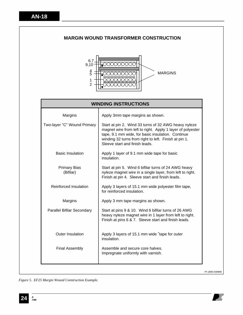
Finished Margin Wound Transformer DesignThe information required to assemble a transformer specificationfor the margin wound transformer example is summarized inTable 5. A completed transformer schematic diagram and partslist are shown in Figure 4. A construction drawing is shown inFigure 5.
Bias Wire SizeThe bias winding wire size is chosen to fill as much of thebobbin width as possible. Since there are usually relatively fewprimary bias winding turns, this is best accomplished by usinga bifilar winding rather than a large diameter wire, effectivelydoubling the number of physical turns. The required TC can becalculated as follows:
TCN
BW M
turns cm
B= × ×− ×
= × ×− ×
=
2 102
2 6 1015 1 2 3
13 2
( ) . ( )
. /
From the wire table in Appendix A, the closest wire size withTC greater than or equal to 13.2 turns/cm is 22 AWG, with a TCof 14.25 turns/cm. This is too large a wire size to use with anEF25 core and bobbin. As a compromise, 24 AWG wire is usedinstead. This wire size will not completely cover the availablebobbin width, but is an acceptable compromise for the sake ofmanufacturability. Since the output current of this winding is10 mA or less, there is no need to consider the current capacityof the wire or high frequency skin effect. The wire size in thiscase is determined by space-filling requirements rather thancurrent capacity.
Transformer Construction StyleSince this transformer is a margin wound design for a secondaryregulated application, appropriate construction styles areFigures 7A and 10A. Because this design is for a 15Wapplication, the split primary winding shown in Figure 10A isnot necessary, and more cost effective single section primarydesign of Figure 7A should be used.

A7/96
AN-18
23
Figure 4. Parts List for EF25 Transformer Design Example.
PI-1805-031196
1
2
3
4
5
6
7
8
9
Core, EF25 N67 Mat'l Bobbin, EF25, 10 pin Wire, 32 AWG Heavy Nyleze Wire, 24 AWG Heavy Nyleze Wire, 26 AWG Heavy Nyleze Tape, Polyester 3.0 mm wide Tape, Polyester 9.1 mm wide Tape, Polyester 15.1 mm wide Tubing, Teflon, 24 AWG, 0.4 mm minimum wall thickness
PARTS LIST FOR EF25 TRANSFORMER DESIGN EXAMPLE
1pr.
1ea.
A/R
A/R
A/R
A/R
A/R
A/R
A/R
Item Amt. Description Part # Manufacturer
B66317-G-X167* B66208-A1110-T1 #44 #1296 #1296
Siemens Siemens 3M 3M 3M
SPECIFICATIONS
Primary Inductance - 1884 µH ±15% Leakage Inductance < 45 µH
Pin 1
Primary 65T
#32 AWG
Pin 2Pin 4
Bifilar Primary Bias
6T 2x #24 AWG
Pin 5
Pin 9, 10
Pin 6, 7
Bifilar 12V Secondary
6T 2x #26 AWG
*Gap for ALG of 441 nH/T2 ± 5%
AN-18
A7/9624
Figure 5. EF25 Margin Wound Construction Example.
PI-1806-030896
Margins
Two-layer "C" Wound Primary
Basic Insulation
Primary Bias(Bifilar)
Reinforced Insulation
Margins
Parallel Bifilar Secondary
Outer Insulation
Final Assembly
Apply 3mm tape margins as shown.
Start at pin 2. Wind 33 turns of 32 AWG heavy nyleze magnet wire from left to right. Apply 1 layer of polyester tape, 9.1 mm wide, for basic insulation. Continue winding 32 turns from right to left. Finish at pin 1. Sleeve start and finish leads.
Apply 1 layer of 9.1 mm wide tape for basic insulation.
Start at pin 5. Wind 6 bifilar turns of 24 AWG heavy nyleze magnet wire in a single layer, from left to right. Finish at pin 4. Sleeve start and finish leads.
Apply 3 layers of 15.1 mm wide polyester film tape,for reinforced insulation.
Apply 3 mm tape margins as shown.
Start at pins 9 & 10. Wind 6 bifilar turns of 26 AWG heavy nyleze magnet wire in 1 layer from left to right. Finish at pins 6 & 7. Sleeve start and finish leads.
Apply 3 layers of 15.1 mm wide tape for outer insulation.
Assemble and secure core halves. Impregnate uniformly with varnish.
WINDING INSTRUCTIONS
9,10
45
12
6,7
MARGINS
MARGIN WOUND TRANSFORMER CONSTRUCTION
A7/96
AN-18
25
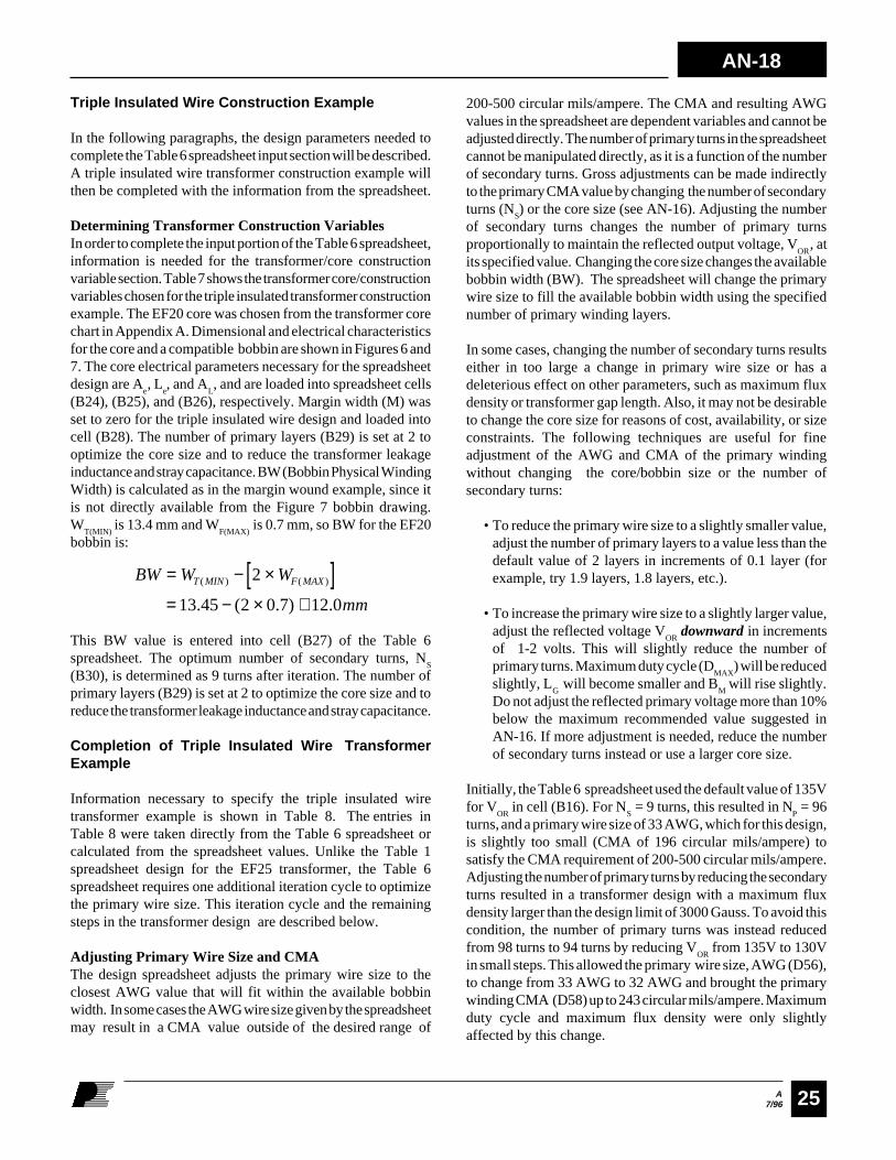
Triple Insulated Wire Construction Example
In the following paragraphs, the design parameters needed tocomplete the Table 6 spreadsheet input section will be described.A triple insulated wire transformer construction example willthen be completed with the information from the spreadsheet.
Determining Transformer Construction VariablesIn order to complete the input portion of the Table 6 spreadsheet,information is needed for the transformer/core constructionvariable section. Table 7 shows the transformer core/constructionvariables chosen for the triple insulated transformer constructionexample. The EF20 core was chosen from the transformer corechart in Appendix A. Dimensional and electrical characteristicsfor the core and a compatible bobbin are shown in Figures 6 and7. The core electrical parameters necessary for the spreadsheetdesign are A
e, L
e, and A
L, and are loaded into spreadsheet cells
(B24), (B25), and (B26), respectively. Margin width (M) wasset to zero for the triple insulated wire design and loaded intocell (B28). The number of primary layers (B29) is set at 2 tooptimize the core size and to reduce the transformer leakageinductance and stray capacitance. BW (Bobbin Physical WindingWidth) is calculated as in the margin wound example, since itis not directly available from the Figure 7 bobbin drawing.W
T(MIN) is 13.4 mm and W
F(MAX) is 0.7 mm, so BW for the EF20
bobbin is:
200-500 circular mils/ampere. The CMA and resulting AWGvalues in the spreadsheet are dependent variables and cannot beadjusted directly. The number of primary turns in the spreadsheetcannot be manipulated directly, as it is a function of the numberof secondary turns. Gross adjustments can be made indirectlyto the primary CMA value by changing the number of secondaryturns (N
S) or the core size (see AN-16). Adjusting the number
of secondary turns changes the number of primary turnsproportionally to maintain the reflected output voltage, V
OR, at
its specified value. Changing the core size changes the availablebobbin width (BW). The spreadsheet will change the primarywire size to fill the available bobbin width using the specifiednumber of primary winding layers.
In some cases, changing the number of secondary turns resultseither in too large a change in primary wire size or has adeleterious effect on other parameters, such as maximum fluxdensity or transformer gap length. Also, it may not be desirableto change the core size for reasons of cost, availability, or sizeconstraints. The following techniques are useful for fineadjustment of the AWG and CMA of the primary windingwithout changing the core/bobbin size or the number ofsecondary turns:
• To reduce the primary wire size to a slightly smaller value,adjust the number of primary layers to a value less than thedefault value of 2 layers in increments of 0.1 layer (forexample, try 1.9 layers, 1.8 layers, etc.).
• To increase the primary wire size to a slightly larger value,adjust the reflected voltage V
OR downward in increments
of 1-2 volts. This will slightly reduce the number ofprimary turns. Maximum duty cycle (D
MAX) will be reduced
slightly, LG will become smaller and B
M will rise slightly.
Do not adjust the reflected primary voltage more than 10%below the maximum recommended value suggested inAN-16. If more adjustment is needed, reduce the numberof secondary turns instead or use a larger core size.
Initially, the Table 6 spreadsheet used the default value of 135Vfor V
OR in cell (B16). For N
S = 9 turns, this resulted in N
P = 96
turns, and a primary wire size of 33 AWG, which for this design,is slightly too small (CMA of 196 circular mils/ampere) tosatisfy the CMA requirement of 200-500 circular mils/ampere.Adjusting the number of primary turns by reducing the secondaryturns resulted in a transformer design with a maximum fluxdensity larger than the design limit of 3000 Gauss. To avoid thiscondition, the number of primary turns was instead reducedfrom 98 turns to 94 turns by reducing V
OR from 135V to 130V
in small steps. This allowed the primary wire size, AWG (D56),to change from 33 AWG to 32 AWG and brought the primarywinding CMA (D58) up to 243 circular mils/ampere. Maximumduty cycle and maximum flux density were only slightlyaffected by this change.
BW W W
mm
T MIN F MAX= − ×[ ]= − × ≅
( ) ( )
. ( . ) .
2
13 45 2 0 7 12 0
This BW value is entered into cell (B27) of the Table 6spreadsheet. The optimum number of secondary turns, N
S
(B30), is determined as 9 turns after iteration. The number ofprimary layers (B29) is set at 2 to optimize the core size and toreduce the transformer leakage inductance and stray capacitance.
Completion of Triple Insulated Wire TransformerExample
Information necessary to specify the triple insulated wiretransformer example is shown in Table 8. The entries inTable 8 were taken directly from the Table 6 spreadsheet orcalculated from the spreadsheet values. Unlike the Table 1spreadsheet design for the EF25 transformer, the Table 6spreadsheet requires one additional iteration cycle to optimizethe primary wire size. This iteration cycle and the remainingsteps in the transformer design are described below.
Adjusting Primary Wire Size and CMAThe design spreadsheet adjusts the primary wire size to theclosest AWG value that will fit within the available bobbinwidth. In some cases the AWG wire size given by the spreadsheetmay result in a CMA value outside of the desired range of
AN-18
A7/9626
123456789
1 01 11 21 31 41 51 61 71 81 92 02 12 22 32 42 52 62 72 82 93 03 13 23 33 43 53 63 73 83 94 04 14 24 34 44 54 64 74 84 95 05 15 25 35 45 55 65 75 85 96 06 16 26 36 46 56 66 76 86 97 07 17 27 37 47 57 67 77 87 98 08 18 2
A B C D E F INPUT OUTPUTENTER APPLICATION VARIABLESVACMIN 8 5 Volts Minimum AC Input VoltageVACMAX 265 Volts Maximum AC Input VoltagefL 5 0 Hertz AC Mains FrequencyfS 100000 Hertz TOPSwitch Switching FrequencyVO 1 2 Volts Output VoltagePO 1 5 Watts Output Powern 0.8 Efficiency EstimateZ 0.5 Loss Allocation Factor VB 1 2 Volts Bias VoltagetC 3 mSeconds Bridge Rectifier Conduction Time EstimateCIN 4 7 uFarads Input Filter Capacitor
ENTER TOPSWITCH VARIABLESVOR 130 Volts Reflected Output VoltageVDS 1 0 Volts TOPSwitch on-state Drain to Source Voltage VD 0.4 Volts Output Winding Diode Forward Voltage DropVDB 0.7 Volts Bias Winding Diode Forward Voltage DropKRP 0.60 Ripple to Peak Current Ratio (0.4 < KRP < 1.0)
ENTER TRANSFORMER CORE/CONSTRUCTION VARIABLESEF20 Core Type
AE 0.335 cm^2 Core Effective Cross Sectional AreaLE 4.49 cm Core Effective Path LengthAL 1470 nH/T^2 Ungapped Core Effective InductanceBW 1 2 mm Bobbin Physical Winding WidthM 0 mm Safety Margin Width (Half the Primary to Secondary Creepage Distance)L 2 Number of Primary LayersNS 9 Number of Secondary Turns
DC INPUT VOLTAGE PARAMETERSVMIN 9 4 Volts Minimum DC Input VoltageVMAX 375 Volts Maximum DC Input Voltage
CURRENT WAVEFORM SHAPE PARAMETERSDMAX 0.61 Duty Cycle at Minimum DC Input Voltage (VMIN)IAVG 0.20 Amps Average Primary CurrentIP 0.47 Amps Peak Primary CurrentIR 0.28 Amps Primary Ripple CurrentIRMS 0.26 Amps Primary RMS Current
TRANSFORMER PRIMARY DESIGN PARAMETERSLP 1829 uHenries Primary InductanceNP 9 4 Primary Winding Number of TurnsNB 9 Bias Winding Number of TurnsALG 205 nH/T^2 Gapped Core Effective InductanceBM 2 7 1 2 Gauss Maximum Flux Density (2000 < BM < 3000)BAC 814 Gauss AC Flux Density for Core Loss Curves (0.5 X Peak to Peak)ur 1568 Relative Permeability of Ungapped CoreLG 0.18 mm Gap Length (Lg >> 0.051 mm)BWE 2 4 mm Effective Bobbin WidthOD 0.25 mm Maximum Primary Wire Diameter including insulationINS 0.05 mm Estimated Total Insulation Thickness (= 2 * film thickness)DIA 0.21 mm Bare conductor diameterAWG 3 2 AWG Primary Wire Gauge (Rounded to next smaller standard AWG value)CM 6 4 Cmils Bare conductor effective area in circular milsCMA 2 4 3 Cmils/Amp Primary Winding Current Capacity (200 < CMA < 500)
TRANSFORMER SECONDARY DESIGN PARAMETERSISP 4.91 Amps Peak Secondary CurrentISRMS 2.22 Amps Secondary RMS CurrentIO 1.25 Amps Power Supply Output CurrentIRIPPLE 1.84 Amps Output Capacitor RMS Ripple Current
CMS 540 Cmils Secondary Bare Conductor minimum circular milsAWGS 2 2 AWG Secondary Wire Gauge (Rounded up to next larger standard AWG value)DIAS 0.65 mm Secondary Minimum Bare Conductor DiameterODS 1.33 mm Secondary Maximum Insulated Wire Outside DiameterINSS 0.34 mm Maximum Secondary Insulation Wall Thickness
VOLTAGE STRESS PARAMETERSVDRAIN 668 Volts Maximum Drain Voltage Estimate (Includes Effect of Leakage Inductance)PIVS 4 8 Volts Output Rectifier Maximum Peak Inverse VoltagePIVB 4 9 Volts Bias Rectifier Maximum Peak Inverse Voltage
ADDITIONAL OUTPUTSVX 1 2 Volts Auxiliary Output VoltageVDX 0.7 Volts Auxiliary Diode Forward Voltage DropNX 9.22 Auxiliary Number of TurnsPIVX 4 9 Volts Auxiliary Rectifier Maximum Peak Inverse Voltage
Table 6. Design Spreadsheet for 15 W Triple Insulated Wire Transformer.

A7/96
AN-18
27
DESCRIPTION
Core Type
Core Effective CrossSectional Area
Core Effective Path Length
Core UngappedInductance Coefficient
Bobbin Physical Winding Width
Margin Width
Number of PrimaryWinding Layers
Number ofSecondary Turns
CELL #
B23
B24
B25
B26
B27
B28
B29
B30
TRANSFORMER CONSTRUCTION VARIABLES(INPUT TO TABLE 6 SPREADSHEET)
SYMBOL
-
Ae
Le
AL
BW
M
L
NS
VALUE
EF20
0.335 cm2
4.49 cm
1470 nH/T2
12.0 mm
0
2
9 t
SOURCE
Core Specification
Core Specification
Core Specification
Core Specification
Calculated from BobbinSpecification
Default Value fromAN-16
Default Value fromAN-16
See Text
Table 7. Transformer Construction Variables for EF20 Triple Insulated Wire Design.
Figure 6. EF20 Core.
10.2 -0.4
5.9
5.9
-0.5
20.4-0.8
14.1+0.6
7 +0.5
PI-1821-040296
-0.4
Electrical Characteristics
Ae = 0.335 cm2
le = 4.49 cm
AL = 1470 nH/T2
All Dimensions are in mm
22
14.6
max
3.5
-0.5
2-0
.1
7.6 -0
.15
6.1
+0.
2
-0.3
13.9-0.2513.7
-0.250.6 ±0.1 0.6
0.45
±0.16.1+0.15
PI-1822-040296All Dimensions are in mm
(WT)(WF)
Figure 7. EF20 Bobbin.

AN-18
A7/9628
DESCRIPTION
Core Type, Material,Part #
Bobbin Type,Part #
Number of Primary Turns
Number of Secondary Turns
Number of Bias Winding Turns
Primary Wire Size
Secondary Wire Size
Bias Winding Wire Size
Core Gapped InductanceCoefficient
Primary Inductance
Reinforced InsulationTape Width
Basic InsulationTape Width
Margin Tape Width
Sleeving Size
CELL #
-
-
D45
B30
D46
D56
D67 (See Text)
See Text
C47
D44
B27
See Text
B28
N/A
VALUE
EF20, Siemens N67Part# B66311-G-X130
EF20, 10 PIN, Siemens PINB66206-A 1110-T1
94 turns
9 turns
9 turns
32 AWG
26 AWG Triple Insulated
24 AWG
205 nH/T2 ±5%
1829 µH +/-10%
N/A
12.0 cm
N/A
N/A
TRIPLE INSULATED WIRE TRANSFORMER CONSTRUCTIONPARAMETERS FROM TABLE 6 SPREADSHEET
Table 8. Construction Parameters for Triple Insulated Wire Design Example.
SYMBOL
-
-
NP
NS
NB
AWG
AWGS
AWGB
ALG
LP
BW
M
-
Secondary Wire SizeFrom cell ( B66) of the Table 6 spreadsheet, a secondary barewire area of 540 circular mils is required to make the secondaryCMA equal the primary CMA. From cell (D67), the closestAWG wire size that can satisfy this requirement with a singlewire is calculated as 22 AWG. This wire size is too large for useat 100KHz, and several smaller parallel wires should be usedinstead to allow full utilization of the wire cross-sectional area.From the wire table in Appendix A, it can be seen that twoparallel strands of 26 AWG triple insulated wire (CM of 252.8circular mils per wire) have a total bare wire area of 505.6circular mils, which is within 10% of the required CM of 540
circular mils. The current capacity of the parallel winding canbe calculated from the formula:
CMAN CM
ISSRMS
= ×
CMAS is the current capacity of the secondary winding in
circular mils per ampere, N is the number of strands in thesecondary winding, CM is the bare area of a single secondaryconductor in circular mils (from the wire table in Appendix A),and I
SRMS is the secondary RMS current from cell (D62) of the
A7/96
AN-18
29
spreadsheet. 26 AWG wire has a bare area of 252.8 circularmils. Two parallel strands of 26 AWG triple insulated wire havea current capacity of:
CMAS =×
=2 252 8
2 25224 7
.
.. circular mils/ampere
This value is within 10% of the primary CMA of 243 circularmils/ampere, and satisfies the CMA limit of 200-500 circularmils per ampere.
Bias Wire SizeThe bias winding wire size is chosen to fill as much of thebobbin width as possible. Since there are usually relatively fewturns on the primary bias winding, this is best accomplished byusing a bifilar winding rather than a large diameter wire,effectively doubling the number of physical turns. The requiredTC to fill a single layer can be calculated as follows:
TCN
BW M
turns cm
B= × ×− ×
= × ×− ×
=
2 102
2 9 1012 2 0
15
( ) ( )
/
From the wire table, the closest wire size with a TC greater thanor equal to this value is 23 AWG, with a TC
of 15.82 turns/cm.
This wire is too large to use with a small bobbin. A compromiseis to use the next smallest size, 24 AWG, which will not fill thebobbin width completely, but is easier to terminate to thebobbin pins. Since the output current of this winding is 10 mA
or less, there is no need to consider the current capacity of thewire. The wire size in this case is determined by fill factorrequirements rather than current capacity.
Transformer Construction StyleSince this transformer is a triple insulated wire design for asecondary regulated application, appropriate construction stylesare Figure 7B and 10B. Because this design is for a 15Wapplication, a split primary winding as shown in Figure 10B isnot necessary, and the more cost effective single section primarydesign of Figure 7B should be used.
Tape SizesSince this is a triple insulated design, one size of tape is requiredfor basic insulation, with a width equal to BW. From cell (B27)of the Table 6 spreadsheet, this is 12.0 mm.
Insulating Sleeving SizeSince this is a triple insulated wire design, no sleeving isrequired
Gapped Core Inductance CoefficientThe A
LG for this transformer design is given in cell (C47) of the
design spreadsheet, and should be used as the center value forspecifying the core A
LG on the transformer specification.
Finished Triple Insulated Wire Transformer DesignThe information required to assemble a transformer specificationfor the triple insulated wire transformer example is summarizedin Table 8. A completed transformer schematic diagram andparts list are shown in Figure 8. A construction drawing isshown in Figure 9.
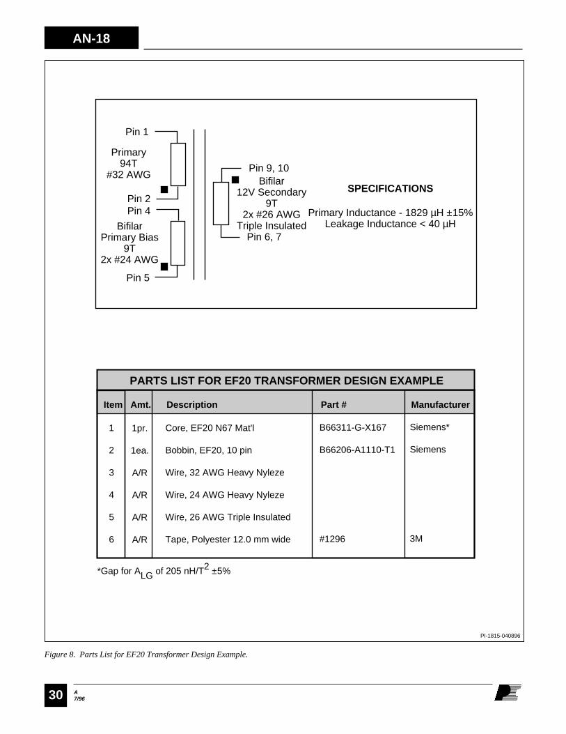
AN-18
A7/9630
PI-1815-040896
1
2
3
4
5
6
Core, EF20 N67 Mat'l
Bobbin, EF20, 10 pinWire, 32 AWG Heavy Nyleze
Wire, 24 AWG Heavy Nyleze
Wire, 26 AWG Triple Insulated
Tape, Polyester 12.0 mm wide
PARTS LIST FOR EF20 TRANSFORMER DESIGN EXAMPLE
1pr.
1ea.
A/R
A/R
A/R
A/R
Item Amt. Description Part # Manufacturer
B66311-G-X167
B66206-A1110-T1
#1296
Siemens*
Siemens
3M
SPECIFICATIONS
Primary Inductance - 1829 µH ±15%Leakage Inductance < 40 µH
Pin 1
Primary94T
#32 AWG
Pin 2Pin 4
BifilarPrimary Bias
9T2x #24 AWG
Pin 5
Pin 9, 10
Pin 6, 7
Bifilar12V Secondary
9T2x #26 AWG
Triple Insulated
*Gap for ALG of 205 nH/T2 ±5%
Figure 8. Parts List for EF20 Transformer Design Example.

A7/96
AN-18
31
Figure 9. EF20 Triple Insulated Design Example.
PI-1816-032896
Two-layer "C" Wound Primary
Basic Insulation
Primary Bias(Bifilar)
Basic Insulation
Parallel Bifilar Triple Insulated Secondary
Outer Insulation
Final Assembly
Start at pin 2. Wind 47 turns of 32 AWG heavy nylezewire from left to right. Apply 1 layer of polyester film tape, 12.0 mm wide, for basic insulation. Continue winding 47 turns from right to left. Finish at pin 1.
Apply 1 layer of 12.0 mm wide tape for basic insulation.
Start at pin 5. Wind 9 bifilar turns of 24 AWG heavy nyleze wire in a single layer, from left to right. Finish at pin 4.
Apply 1 layer of 12.0 mm wide tape for basic insulation.
Start at pin 9 & 10. Wind 9 bifilar turns of 26 AWG triple insulated wire in approximately 1 layer from left to right. Finish at pin 6 & 7.
Apply 3 layers of 12.0 mm wide tape for outer insulation.
Assemble and secure core halves. Impregnate uniformly with varnish.
WINDING INSTRUCTIONS
9,10
45
12
6,7
TRIPLE INSULATED TRANSFORMER CONSTRUCTION
AN-18
A7/9632
References1) Power Integrations, Inc., AN-15, "Power Supply DesignTechniques for EMI and Safety"
2) Power Integrations, Inc., AN-16, "TOPSwitch FlybackFundamentals"
3) Power Integrations, Inc., AN-17, “Flyback TransformerDesign for TOPSwitch Power Supplies”
4) Power Integrations, Inc. DN-8, “Simple Bias Supplies Usingthe TOP200”
5) Col. William McLyman, Transformer and Inductor DesignHandbook, New York, Marcel Dekker, Inc., 1978
6) Col. William McLyman, Magnetic Core Selection forTransformers and Inductors, New York, Marcel Dekker, Inc.,1982
7) Abraham I. Pressman, Switching Power Supply Design (2nded.), New York, McGraw-Hill, Inc., 1991
8) Ferdinand C. Geerlings, “SMPS Power Inductor andTransformer Design, Part 1”, Powerconversion International,November/December 1979, pp. 45-52
9) Ferdinand C. Geerlings, “SMPS Power Inductor Design andTransformer Design, Part 2”, Powerconversion International,January/February 1980, pp. 33-40
10) Coilcraft, Inc., Technical Note Number 8110, “V.D.E.Transformer Safety Requirements”
JAPANPower Integrations, K.K.Keihin-Tatemono 1st Bldg.12-20 Shin-Yokohama 2-Chome, Kohoku-ku,Yokohama-shi, Kanagawa 222JapanPhone: 81•(0)•45•471•1021Fax: 81•(0)•45•471•3717
ASIA & OCEANIAFor Your Nearest Sales/Rep OfficePlease Contact Customer ServicePhone: 408•523•9265Fax: 408•523•9365
WORLD HEADQUARTERSPower Integrations, Inc.477 N. Mathilda AvenueSunnyvale, CA 94086USAMain: 408•523•9200Customer Service:Phone: 408•523•9265Fax: 408•523•9365
AMERICASFor Your Nearest Sales/Rep OfficePlease Contact Customer ServicePhone: 408•523•9265Fax: 408•523•9365
Power Integrations reserves the right to make changes to its products at any time to improve reliability or manufacturability.Power Integrations does not assume any liability arising from the use of any device or circuit described herein, nor does itconvey any license under its patent rights or the rights of others.
PI Logo and TOPSwitch are registered trademarks of Power Integrations, Inc.©Copyright 1994, Power Integrations, Inc. 477 N. Mathilda Avenue, Sunnyvale, CA 94086
APPLICATIONS HOTLINEWorld Wide 408•523•9260
APPLICATIONS FAXAmericas 408•523•9361Europe/Africa44•(0)•1753•622•209Japan 81•(0)•45•471•3717Asia/Oceania 408•523•9364
EUROPE & AFRICAPower Integrations (Europe) Ltd.Mountbatten HouseFairacresWindsor SL4 4LEUnited KingdomPhone: 44•(0)•1753•622•208Fax: 44•(0)•1753•622•209