power feed 11 semiautomatic cabinet wire feeder operator's manual im613-b
TRANSCRIPT

Power Feed 11 SemiAutomaticCabinet Wire Feeder
OPERATOR’S MANUAL
IM613-BOctober, 2000
Safety Depends on YouLincoln arc welding and cuttingequipment is designed and builtwith safety in mind. However, youroverall safety can be increased byproper installation ... and thought-ful operation on your part. DONOT INSTALL, OPERATE ORREPAIR THIS EQUIPMENTWITHOUT READING THISMANUAL AND THE SAFETYPRECAUTIONS CONTAINEDTHROUGHOUT. And, mostimportantly, think before you actand be careful.
For use with: Power Feed 11 K1635-1 (World Model) Code 10529; 10777Power Feed 11 K1636-1 (European Model) Code 10531; 10778
• Sales and Service through Subsidiaries and Distributors Worldwide •
Cleveland, Ohio 44117-1199 U.S.A. TEL: 216.481.8100 FAX: 216.486.1751 WEB SITE: www.lincolnelectric.com
• World's Leader in Welding and Cutting Products •
Date of Purchase:Serial Number:Code Number:Model:Where Purchased:
Copyright © 2000 Lincoln Global Inc.
This manual covers equipment which is no longer in production by The Lincoln Electric Co. Speci�cations and availability of optional features may have changed.
FOR ENGINEpowered equipment.
1.a. Turn the engine off before troubleshooting and maintenancework unless the maintenance work requires it to be running.
____________________________________________________1.b. Operate engines in open, well-ventilated
areas or vent the engine exhaust fumes outdoors.
____________________________________________________1.c. Do not add the fuel near an open flame
welding arc or when the engine is running.Stop the engine and allow it to cool beforerefueling to prevent spilled fuel from vaporiz-ing on contact with hot engine parts andigniting. Do not spill fuel when filling tank. Iffuel is spilled, wipe it up and do not startengine until fumes have been eliminated.
____________________________________________________1.d. Keep all equipment safety guards, covers and devices in
position and in good repair.Keep hands, hair, clothing andtools away from V-belts, gears, fans and all other movingparts when starting, operating or repairing equipment.
____________________________________________________
1.e. In some cases it may be necessary to remove safetyguards to perform required maintenance. Removeguards only when necessary and replace them when themaintenance requiring their removal is complete.Always use the greatest care when working near movingparts.
___________________________________________________1.f. Do not put your hands near the engine fan.
Do not attempt to override the governor oridler by pushing on the throttle control rodswhile the engine is running.
___________________________________________________1.g. To prevent accidentally starting gasoline engines while
turning the engine or welding generator during maintenancework, disconnect the spark plug wires, distributor cap ormagneto wire as appropriate.
iSAFETYi
ARC WELDING CAN BE HAZARDOUS. PROTECT YOURSELF AND OTHERS FROM POSSIBLE SERIOUS INJURY OR DEATH.KEEP CHILDREN AWAY. PACEMAKER WEARERS SHOULD CONSULT WITH THEIR DOCTOR BEFORE OPERATING.
Read and understand the following safety highlights. For additional safety information, it is strongly recommended that youpurchase a copy of “Safety in Welding & Cutting - ANSI Standard Z49.1” from the American Welding Society, P.O. Box351040, Miami, Florida 33135 or CSA Standard W117.2-1974. A Free copy of “Arc Welding Safety” booklet E205 is availablefrom the Lincoln Electric Company, 22801 St. Clair Avenue, Cleveland, Ohio 44117-1199.
BE SURE THAT ALL INSTALLATION, OPERATION, MAINTENANCE AND REPAIR PROCEDURES AREPERFORMED ONLY BY QUALIFIED INDIVIDUALS.
WARNING
Mar ‘95
ELECTRIC AND MAGNETIC FIELDSmay be dangerous
2.a. Electric current flowing through any conductor causes localized Electric and Magnetic Fields (EMF). Welding current creates EMF fields around welding cables and welding machines
2.b. EMF fields may interfere with some pacemakers, andwelders having a pacemaker should consult their physicianbefore welding.
2.c. Exposure to EMF fields in welding may have other healtheffects which are now not known.
2.d. All welders should use the following procedures in order tominimize exposure to EMF fields from the welding circuit:
2.d.1. Route the electrode and work cables together - Securethem with tape when possible.
2.d.2. Never coil the electrode lead around your body.
2.d.3. Do not place your body between the electrode andwork cables. If the electrode cable is on your right side, the work cable should also be on your right side.
2.d.4. Connect the work cable to the workpiece as close aspossible to the area being welded.
2.d.5. Do not work next to welding power source.
1.h. To avoid scalding, do not remove theradiator pressure cap when the engine ishot.
CALIFORNIA PROPOSITION 65 WARNINGS
Diesel engine exhaust and some of its constituentsare known to the State of California to cause can-cer, birth defects, and other reproductive harm.
The engine exhaust from this product containschemicals known to the State of California to causecancer, birth defects, or other reproductive harm.
The Above For Diesel Engines The Above For Gasoline Engines

iiSAFETYii
ARC RAYS can burn.4.a. Use a shield with the proper filter and cover
plates to protect your eyes from sparks andthe rays of the arc when welding or observingopen arc welding. Headshield and filter lensshould conform to ANSI Z87. I standards.
4.b. Use suitable clothing made from durable flame-resistantmaterial to protect your skin and that of your helpers fromthe arc rays.
4.c. Protect other nearby personnel with suitable, non-flammablescreening and/or warn them not to watch the arc nor exposethemselves to the arc rays or to hot spatter or metal.
ELECTRIC SHOCK cankill.3.a. The electrode and work (or ground) circuits
are electrically “hot” when the welder is on.Do not touch these “hot” parts with your bareskin or wet clothing. Wear dry, hole-free
gloves to insulate hands.
3.b. Insulate yourself from work and ground using dry insulation.Make certain the insulation is large enough to cover your fullarea of physical contact with work and ground.
In addition to the normal safety precautions, if weldingmust be performed under electrically hazardousconditions (in damp locations or while wearing wetclothing; on metal structures such as floors, gratings orscaffolds; when in cramped positions such as sitting,kneeling or lying, if there is a high risk of unavoidable oraccidental contact with the workpiece or ground) usethe following equipment:
• Semiautomatic DC Constant Voltage (Wire) Welder.• DC Manual (Stick) Welder.• AC Welder with Reduced Voltage Control.
3.c. In semiautomatic or automatic wire welding, the electrode,electrode reel, welding head, nozzle or semiautomaticwelding gun are also electrically “hot”.
3.d. Always be sure the work cable makes a good electricalconnection with the metal being welded. The connectionshould be as close as possible to the area being welded.
3.e. Ground the work or metal to be welded to a good electrical(earth) ground.
3.f. Maintain the electrode holder, work clamp, welding cable andwelding machine in good, safe operating condition. Replacedamaged insulation.
3.g. Never dip the electrode in water for cooling.
3.h. Never simultaneously touch electrically “hot” parts ofelectrode holders connected to two welders because voltagebetween the two can be the total of the open circuit voltageof both welders.
3.i. When working above floor level, use a safety belt to protectyourself from a fall should you get a shock.
3.j. Also see Items 6.c. and 8.
FUMES AND GASEScan be dangerous.5.a. Welding may produce fumes and gases
hazardous to health. Avoid breathing thesefumes and gases.When welding, keepyour head out of the fume. Use enoughventilation and/or exhaust at the arc to keep
fumes and gases away from the breathing zone. Whenwelding with electrodes which require specialventilation such as stainless or hard facing (seeinstructions on container or MSDS) or on lead orcadmium plated steel and other metals or coatingswhich produce highly toxic fumes, keep exposure aslow as possible and below Threshold Limit Values (TLV)using local exhaust or mechanical ventilation. Inconfined spaces or in some circumstances, outdoors, arespirator may be required. Additional precautions arealso required when welding on galvanized steel.
5.b. Do not weld in locations near chlorinated hydrocarbon vaporscoming from degreasing, cleaning or spraying operations.
The heat and rays of the arc can react with solvent vapors toform phosgene, a highly toxic gas, and other irritating products.
5.c. Shielding gases used for arc welding can displace air andcause injury or death. Always use enough ventilation,especially in confined areas, to insure breathing air is safe.
5.d. Read and understand the manufacturer’s instructions for thisequipment and the consumables to be used, including thematerial safety data sheet (MSDS) and follow youremployer’s safety practices. MSDS forms are available fromyour welding distributor or from the manufacturer.
5.e. Also see item 1.b. Mar ‘95

FOR ELECTRICALLYpowered equipment.
8.a. Turn off input power using the disconnectswitch at the fuse box before working onthe equipment.
8.b. Install equipment in accordance with the U.S. NationalElectrical Code, all local codes and the manufacturer’srecommendations.
8.c. Ground the equipment in accordance with the U.S. NationalElectrical Code and the manufacturer’s recommendations.
CYLINDER may explodeif damaged.7.a. Use only compressed gas cylinders
containing the correct shielding gas for theprocess used and properly operatingregulators designed for the gas and
pressure used. All hoses, fittings, etc. should be suitable forthe application and maintained in good condition.
7.b. Always keep cylinders in an upright position securelychained to an undercarriage or fixed support.
7.c. Cylinders should be located:• Away from areas where they may be struck or subjected tophysical damage.
• A safe distance from arc welding or cutting operations andany other source of heat, sparks, or flame.
7.d. Never allow the electrode, electrode holder or any otherelectrically “hot” parts to touch a cylinder.
7.e. Keep your head and face away from the cylinder valve outletwhen opening the cylinder valve.
7.f. Valve protection caps should always be in place and handtight except when the cylinder is in use or connected foruse.
7.g. Read and follow the instructions on compressed gascylinders, associated equipment, and CGA publication P-l,“Precautions for Safe Handling of Compressed Gases inCylinders,” available from the Compressed Gas Association1235 Jefferson Davis Highway, Arlington, VA 22202.
iiiSAFETYiii
Mar ‘95
WELDING SPARKS cancause fire or explosion.6.a. Remove fire hazards from the welding area.
If this is not possible, cover them to preventthe welding sparks from starting a fire.Remember that welding sparks and hot
materials from welding can easily go through small cracksand openings to adjacent areas. Avoid welding nearhydraulic lines. Have a fire extinguisher readily available.
6.b. Where compressed gases are to be used at the job site,special precautions should be used to prevent hazardoussituations. Refer to “Safety in Welding and Cutting” (ANSIStandard Z49.1) and the operating information for theequipment being used.
6.c. When not welding, make certain no part of the electrodecircuit is touching the work or ground. Accidental contactcan cause overheating and create a fire hazard.
6.d. Do not heat, cut or weld tanks, drums or containers until theproper steps have been taken to insure that such procedureswill not cause flammable or toxic vapors from substancesinside. They can cause an explosion even though they havebeen “cleaned”. For information, purchase “RecommendedSafe Practices for the Preparation for Welding and Cutting ofContainers and Piping That Have Held HazardousSubstances”, AWS F4.1 from the American Welding Society(see address above).
6.e. Vent hollow castings or containers before heating, cutting orwelding. They may explode.
6.f. Sparks and spatter are thrown from the welding arc. Wear oilfree protective garments such as leather gloves, heavy shirt,cuffless trousers, high shoes and a cap over your hair. Wearear plugs when welding out of position or in confined places.Always wear safety glasses with side shields when in awelding area.
6.g. Connect the work cable to the work as close to the weldingarea as practical. Work cables connected to the buildingframework or other locations away from the welding areaincrease the possibility of the welding current passingthrough lifting chains, crane cables or other alternate cir-cuits. This can create fire hazards or overheat lifting chainsor cables until they fail.
6.h. Also see item 1.c.

ivSAFETYiv
PRÉCAUTIONS DE SÛRETÉPour votre propre protection lire et observer toutes les instructionset les précautions de sûreté specifiques qui parraissent dans cemanuel aussi bien que les précautions de sûreté générales suiv-antes:
Sûreté Pour Soudage A L’Arc1. Protegez-vous contre la secousse électrique:
a. Les circuits à l’électrode et à la piéce sont sous tensionquand la machine à souder est en marche. Eviter toujourstout contact entre les parties sous tension et la peau nueou les vétements mouillés. Porter des gants secs et sanstrous pour isoler les mains.
b. Faire trés attention de bien s’isoler de la masse quand onsoude dans des endroits humides, ou sur un planchermetallique ou des grilles metalliques, principalement dans les positions assis ou couché pour lesquelles une grandepartie du corps peut être en contact avec la masse.
c. Maintenir le porte-électrode, la pince de masse, le câblede soudage et la machine à souder en bon et sûr étatdefonctionnement.
d.Ne jamais plonger le porte-électrode dans l’eau pour lerefroidir.
e. Ne jamais toucher simultanément les parties sous tensiondes porte-électrodes connectés à deux machines à souderparce que la tension entre les deux pinces peut être letotal de la tension à vide des deux machines.
f. Si on utilise la machine à souder comme une source decourant pour soudage semi-automatique, ces precautionspour le porte-électrode s’applicuent aussi au pistolet desoudage.
2. Dans le cas de travail au dessus du niveau du sol, se protégercontre les chutes dans le cas ou on recoit un choc. Ne jamaisenrouler le câble-électrode autour de n’importe quelle partiedu corps.
3. Un coup d’arc peut être plus sévère qu’un coup de soliel,donc:
a. Utiliser un bon masque avec un verre filtrant appropriéainsi qu’un verre blanc afin de se protéger les yeux du ray-onnement de l’arc et des projections quand on soude ouquand on regarde l’arc.
b. Porter des vêtements convenables afin de protéger lapeau de soudeur et des aides contre le rayonnement del‘arc.
c. Protéger l’autre personnel travaillant à proximité ausoudage à l’aide d’écrans appropriés et non-inflammables.
4. Des gouttes de laitier en fusion sont émises de l’arc desoudage. Se protéger avec des vêtements de protection libresde l’huile, tels que les gants en cuir, chemise épaisse, pan-talons sans revers, et chaussures montantes.
5. Toujours porter des lunettes de sécurité dans la zone desoudage. Utiliser des lunettes avec écrans lateraux dans les
zones où l’on pique le laitier.
6. Eloigner les matériaux inflammables ou les recouvrir afin deprévenir tout risque d’incendie dû aux étincelles.
7. Quand on ne soude pas, poser la pince à une endroit isolé dela masse. Un court-circuit accidental peut provoquer unéchauffement et un risque d’incendie.
8. S’assurer que la masse est connectée le plus prés possiblede la zone de travail qu’il est pratique de le faire. Si on placela masse sur la charpente de la construction ou d’autresendroits éloignés de la zone de travail, on augmente le risquede voir passer le courant de soudage par les chaines de lev-age, câbles de grue, ou autres circuits. Cela peut provoquerdes risques d’incendie ou d’echauffement des chaines et descâbles jusqu’à ce qu’ils se rompent.
9. Assurer une ventilation suffisante dans la zone de soudage.Ceci est particuliérement important pour le soudage de tôlesgalvanisées plombées, ou cadmiées ou tout autre métal quiproduit des fumeés toxiques.
10. Ne pas souder en présence de vapeurs de chlore provenantd’opérations de dégraissage, nettoyage ou pistolage. Lachaleur ou les rayons de l’arc peuvent réagir avec les vapeursdu solvant pour produire du phosgéne (gas fortement toxique)ou autres produits irritants.
11. Pour obtenir de plus amples renseignements sur la sûreté,voir le code “Code for safety in welding and cutting” CSAStandard W 117.2-1974.
PRÉCAUTIONS DE SÛRETÉ POURLES MACHINES À SOUDER ÀTRANSFORMATEUR ET ÀREDRESSEUR
1. Relier à la terre le chassis du poste conformement au code del’électricité et aux recommendations du fabricant. Le dispositifde montage ou la piece à souder doit être branché à unebonne mise à la terre.
2. Autant que possible, I’installation et l’entretien du poste seronteffectués par un électricien qualifié.
3. Avant de faires des travaux à l’interieur de poste, la debranch-er à l’interrupteur à la boite de fusibles.
4. Garder tous les couvercles et dispositifs de sûreté à leurplace.
Mar. ‘93

Thank You for selecting a QUALITY product by Lincoln Electric. We want youto take pride in operating this Lincoln Electric Company product••• as much pride as we have in bringing this product to you!
Read this Operators Manual completely before attempting to use this equipment. Save this manual and keep ithandy for quick reference. Pay particular attention to the safety instructions we have provided for your protection.The level of seriousness to be applied to each is explained below:
WARNINGThis statement appears where the information must be followed exactly to avoid serious personal injury orloss of life.
This statement appears where the information must be followed to avoid minor personal injury or damage tothis equipment.
CAUTION
Please Examine Carton and Equipment For Damage ImmediatelyWhen this equipment is shipped, title passes to the purchaser upon receipt by the carrier. Consequently, Claimsfor material damaged in shipment must be made by the purchaser against the transportation company at thetime the shipment is received.
Please record your equipment identification information below for future reference. This information can befound on your machine nameplate.
Model Name & Number _____________________________________
Code & Serial Number _____________________________________
Date of Purchase _____________________________________
Whenever you request replacement parts for or information on this equipment always supply the informationyou have recorded above.
vv

viTABLE OF CONTENTSPage
Installation .......................................................................................................Section ATechnical Specifications.......................................................................................................A-1Safety Precautions ...............................................................................................................A-2Wire Feeder to Power Source Configurations......................................................................A-2
Mounting on Top of the Power Source..........................................................................A-2Hanging.........................................................................................................................A-2On the Floor ..................................................................................................................A-2Control Box Orientation.................................................................................................A-2
Cable Connections ...............................................................................................................A-3Control Cable Connections ...........................................................................................A-3Control Cable Specifications .........................................................................................A-3Typical Cabinet Feeder Connection..............................................................................A-3Control Cable Installation ..............................................................................................A-3Electrode Cable Connections........................................................................................A-3Electrode Cable Installation ..........................................................................................A-3Work Cable Connections ..............................................................................................A-4
Wire Drive Gear Ratio (High or Low Speed) ........................................................................A-4Selecting the Proper Gear Ratio ...................................................................................A-4Changing the Wire Drive Ratio......................................................................................A-4
DIP Switch Setup .................................................................................................................A-6Setting DIP Switches in the Control Box .......................................................................A-6Setting DIP Switches in the Wire Drive .........................................................................A-7
Wire Feed Drive Roll Kits .....................................................................................................A-8Procedure to Install Drive Rolls and Wire Guides ................................................................A-8Gun and Cable Assemblies..................................................................................................A-9Gun Connection Guidelines .................................................................................................A-9GMAW Shielding Gas ........................................................................................................A-10Lifting Handle .....................................................................................................................A-10Optional Features Installation.............................................................................................A-11Optional Panels for Control Box .........................................................................................A-11General Panel Installation Guidelines ................................................................................A-11
Operation ............................................................................................................Section BSafety Precautions ..............................................................................................................B-1Product Description ..............................................................................................................B-1Recommended Processes and Equipment ..........................................................................B-1Duty Cycle ............................................................................................................................B-1Control Box Operation..........................................................................................................B-1
Control Box Panels - Upper Panel ................................................................................B-1Control Box Panels - Set Up Controls Description........................................................B-4Control Box - P.C. Board Adjustments..........................................................................B-4Control Box - Setting Operating Limits..........................................................................B-5Control Box - Using Operating Limits ............................................................................B-5
Wire Drive Operation............................................................................................................B-6Wire Drive Settings - External ..............................................................................................B-6Wire Drive - P.C. Board Adjustments ...................................................................................B-7Wire Reel Loading................................................................................................................B-7Feeding Electrode and Brake Adjustment............................................................................B-8Drive Roll Pressure Setting ..................................................................................................B-8Gas Guard Regulator Setting ...............................................................................................B-8Making a Weld......................................................................................................................B-9Wire Reel Changing .............................................................................................................B-9Wire Feed Overload Protection ............................................................................................B-9Component Status Lights ...................................................................................................B-10
Status Light States ......................................................................................................B-10
Accessories .....................................................................................................Section CDrive Roll and Guide Tube Kits ............................................................................................C-1Other Accessories................................................................................................................C-2
Maintenance ....................................................................................................Section DSafety Precautions ...............................................................................................................D-1Routine Maintenance ...........................................................................................................D-1Avoiding Wire Feeding Problems.........................................................................................D-1Periodic Maintenance...........................................................................................................D-1Procedure for Removing Feedplate from Wire Feeder ........................................................D-1

PageTroubleshooting ..............................................................................................Section E
Safety Precautions ...............................................................................................................E-1Troubleshooting Guide .........................................................................................................E-2
Diagrams .............................................................................................................Section FWiring (Power Feed 11 Wire Feeder) ....................................................................F-1Wiring (Power Feed 11 Control Box) .....................................................................F-2Dimension Print......................................................................................................F-3
Parts Lists .......................................................................................................P315 Series
vii TABLE OF CONTENTS

A-1INSTALLATION
POWER FEED 11
A-1
TECHNICAL SPECIFICATIONS – Power Feed 11COMPLETE UNITS
SPEC.# TYPE LOW SPEED RATIO HIGH SPEED RATIO
The PF-11 is environmentally rated IP21S per IEC60529
Wire Size Wire SizeSpeed Solid Cored Speed Solid Cored
K1635-1 Power Feed 11 50-625 IPM .025 - 1/16 in. .030 - 5/64 in 75 - 1100 IPM .025 - .045 in. .030 - .045 in.Cabinet (1.27-15.9 m/m) (0.6 - 1.6 mm) (0.8 - 2.0 mm) (2.03 - 27.9 m/m) (0.6 - 1.2 mm) (0.8 - 1.2 mm)WireFeeder(World Model)
K1636-1 Power Feed 11 50-625 IPM .025 - 1/16 in. .035 - 5/64 in 75 - 1100 IPM .025 - .045 in. .035 - .045 in.Cabinet (1.27-15.9 m/m) (0.6 - 1.6 mm) (0.9 - 2.0 mm) (2.03 - 27.9 m/m) (0.6 - 1.2 mm) (0.9 - 1.2 mm)WireFeeder(EuropeanModel)
COMPLETE UNITSSPEC.# TYPE INPUT POWER PHYSICAL SIZE• TEMPERATURE RATING
DimensionsHeight Width Depth Weight Operating Storage
K1635-1 Power 40 VDC 20.0 “ 9.0 “ 28.7 “ 61 LbsFeed 11 (508 mm) ( 230 mm) (729 mm) (27.7 Kg)(WorldModel)
+40°C +40°Cto to
K1636-1 Power 40 VDC 20.0 “ 9.0 “ 28.7 “ 61 Lbs -20°C -40°CFeed 11 (508 mm) ( 230 mm) (729 mm) (27.7 Kg)(EuropeanModel)

A-2INSTALLATION
POWER FEED 11
A-2
SAFETY PRECAUTION
WIRE FEEDER TO POWER SOURCECONFIGURATIONS
The Wire Feeder is equipped to operate in the verticalor horizontal position. It is shipped ready for use in thein the vertical position.
MOUNTING ON TOP OF THE POWER SOURCE
The Wire Feeder is shipped with the vertical mountingbracket installed on the bottom of the Feeder. TheFeeder must be placed on top (right side) of thePower Source such that the bolt on the mountingbracket goes thru the hole in the Power Source’s LiftBail and the front hole on the right front foot of themounting bracket is placed over the weld stud on theroof of the Power Source. Use the Wing Nut/washerassembly provided to secure the Feeder to the PowerSource.
Note: The Wire Feeder can also be mounted horizon-tally. See ACCESSORIES section for information onthe Optional Horizontal Mounting Bracket.
HANGING
The Wire Feeder is equipped with 2 insulated LiftingEyes for hanging the Feeder. It is recommended thatthe Lifting Eyes always be used when hanging theFeeder. The Lifting Handles should be used for shortterm carrying of the Feeder
Note: A longer or additional Control Cable may berequired when hanging the Feeder. See ACCES-SORIES section for information on optional ControlCables.
ON THE FLOOR
The Wire Feeder is equipped with aluminum skidswhich protect the enclosure when the Feeder isplaced on the floor in either the horizontal or verticalposition.
CONTROL BOX ORIENTATION
The Control Box is designed to be easily rotated toaccommodate horizontal or vertical positions. The pro-cedure to change the Control Box Orientation is as fol-lows:
1. Open the Wire Drive compartment door.
2. Locate the Retaining Collar(just above the WireDrive unit) and depress the Release Bar andremove the Retaining Collar from the Control Boxmounting shaft.
3. Pull the Control Box out just enough to allow theControl Box to be rotated to the desired positionand then re-install. ( Be sure no leads are pinched)Note: For the Horizontal position the right side ofthe Control Box must be next to the front panelcomponents.
4. Re-install the Retaining Collar. Some light pressureon the Control Box may be necessary to get therelease bar to “click” into the mounting shaftgroove.
ELECTRIC SHOCK cankill.• Only qualified personnel should per-
form this installation.
• Turn off the input power to the power source at thedisconnect switch or fuse box before working onthis equipment. Turn off the input power to anyother equipment connected to the welding systemat the disconnect switch or fuse box before work-ing on this equipment.
• Do not touch electrically hot parts.
• Always connect the Power Wave grounding lug(located inside the reconnect input access door) toa proper safety (Earth) ground.
----------------------------------------------------------------------------------------

A-3INSTALLATION
POWER FEED 11
A-3
CABLE CONNECTIONS
CONTROL CABLE CONNECTIONS
• All system control cables are the same.
• All control cables can be connected end to end toextend their length.
• All system equipment must be connected to a con-trol cable.
Welding systems using the Power Feed 11 offer previ-ously unprecedented flexibility in the connection ofsystem components. This system uses the same typeof control cable between each of the system compo-nents. Connections can be “daisy chained” from onesystem component to another. Since communicationover the control cables is done by a robust communi-cations network, the order of connection of the com-ponents makes no difference. The cables can be con-nected anywhere that there is a mating connector.
CONTROL CABLE SPECIFICATIONS
The cable is a 5 copper conductor cable in a SO-typerubber jacket. There is one 20 gauge twisted pair fornetwork communications. This pair has an impedanceof approximately 120 ohms and a propagation delayper foot of < 2.1 ns. There are two 12 gauge conduc-tors that are used to supply the 40 VDC to the net-work. The fifth wire is 18 gauge and is used as anelectrode sense lead. It is typically connected to thefeed plate on the feed head when that feed head isactive.
NOTE: Maximum cable length between any twonodes is 250'.
TYPICAL CABINET FEEDER CONNECTION
The Control cable is connected from the PowerSource to the Wire Feeder. The Power Feed 11comes standard with an 8 ft. Control Cable.
CONTROL CABLE INSTALLATION:
1. Connect the end of the control cable with the 5-pincable plug to the mating receptacle on the powersource. With the pins and key aligned, plug it intothe power source, rotate the threaded locking ringuntil the connector is completely fastened
2. Connect the end of control cable with the 5-socketend to the mating receptacle on the back of thewire feeder. To connect the cable to the feeder,
aligning the pins and key, plug it into the back ofthe wire feeder head, rotate the threaded lockingring until the connector is completely fastened
Note: Depending on the location of the of the WireFeeder relative to the Power Source a longerControl Cable or additional Control Cable(s) may berequired.See section 2.0 “Optional Features” forinformation on optional Control Cables.
ELECTRODE CABLE CONNECTIONS
Most welding applications run with the electrode beingpositive (+). For those applications, connect the elec-trode cable between the wire feeder and the positive(+) output stud on the power source (located beneaththe spring loaded output cover near the bottom of thecase front).
A work lead must be run from the negative (-) powersource output stud to the work piece. The work piececonnection must be firm and secure, especially ifpulse welding is planned. Excessive voltage drops atthe work piece connection often result in unsatisfacto-ry pulse welding performance.
When negative electrode polarity is required, such asin some Innershield™ applications, install as above,except reverse the output connections at the powersource (electrode cable to the negative (-) stud, andwork cable to the positive (+) stud).
ELECTRODE CABLE INSTALLATION:
The Power Feed 11 comes with an installed electrodecable. Connect the power source end of the cable tothe power source output terminal of the desired polari-ty.
The K1636-1 Power Feed 11 (Europe) electrode cableis equipped with a Twist-Mate™ connector while theK1635-1 Power Feed 11 (World) is equipped with alug connector. Also for both models open the WireDrive compartment door and check that the electrodecable lug is against the Feedplate and that the con-nection is tight. Any electrode cable replacement orextension should be sized according to the specifica-tions given in the work cable connections section .

A-4INSTALLATION
POWER FEED 11
A-4
WORK CABLE CONNECTIONS
Connect a work lead of sufficient size and length (perthe following table) between the proper output termi-nal on the power source and the work. Be sure theconnection to the work makes tight metal-to-metalelectrical contact.
To avoid interference problems with other equipmentand to achieve the best possible operation, route allcables directly to the work or wire feeder. Avoidexcessive lengths, bundle the electrode and groundcables together where practical, and do not coilexcess cable.
Minimum work and electrode cables sizes are as fol-lows:
When using an inverter type power source, Use thelargest welding (electrode and ground) cables that arepractical. At least 3/0 (85 mm2) copper wire — even ifthe average output current would not normally requireit. When pulsing, the pulse current can reach veryhigh levels. Voltage drops can become excessive,leading to poor welding characteristics, if undersizedwelding cables are used.
WIRE DRIVE GEAR RATIO (HIGHOR LOW SPEED)
The speed range capability and drive torque of thePower Feed 11 wire drive can be easily and quicklychanged by changing the external drive gear. ThePower Feed 11 is shipped with both a high speed anda low speed gear. As shipped from the factory, thehigh speed (low torque) gear is installed on the feed-er. If this is the desired gear ratio, no changes needto be made.
SELECTING THE PROPER GEAR RATIO
See the Technical Specifications at the front of thissection for feed speed and wire size capabilities withhigh and low speed gear ratios. To determine whetheryou should be using the high or low speed ratio usethe following guidelines:
- When operating at wire feed speeds above 625 IPM(15.9 m/m), you must have the high speed gear(large 30 tooth, 1.6 inch diameter gear) installed.
- When operating at wire feed speeds below 625 IPM(15.9 m/m), you must have the low speed gear(small 17 tooth, .95 inch diameter gear) installed forall wire sizes because using the low speed ratio pro-vides the maximum available wire feeding force.Note: If you are feeding only .045” (1.2 mm) diame-ter and smaller wires you may, at your option, usethe factory installed high speed ratio.
CHANGING THE WIRE DRIVE RATIO
Changing the ratio requires a gear change and a PCboard switch change. The Power Feed 11 is shippedwith both a high speed and a low speed gear. Asshipped from the factory, the high speed (low torque)gear is installed on the feeder. For identification pur-poses, the low speed (high torque) gear has 17 teethand is .95 inches in diameter. The high speed gearhas 30 teeth and is 1.6 inches in diameter. SeeFigure A.2.
FIGURE A.2 — CHANGING WIRE DRIVE RATIO.
Minimum Copper Work Cable Size, AWG
Up to 100 ft Length (30m)
Current60% Duty
Cycle
500 Amps
600 Amps
3/0 (85 mm2)
3/0 (85 mm2)
DRIVEGEAR
PHILLIPSHEAD SCREW
WIREFEEDER

A-5INSTALLATION
POWER FEED 11
A-5
RATIO CHANGE PROCEDURE:
1) Power down the Power Feed by turning OFF itscompanion PowerWave power source. For maxi-mum safety, disconnect the control cable from thePower Feed.
2) Pull open the Wire Feeder’s Compartment Door.
3) Remove the Feedplate per the following:a) Disconnected the Electrode from the Feedplateb) Pull open the Wire Drive Pressure Door.c) Using a 3/16" Hex Key Wrench remove the two
screws that secure the Feedplate to theInterface Plate. These screws are located justbelow and to the right and just below and to leftof the lower drive gears.
d) Swing the rear of the Feedplate out towardsthe front of the machine which will allow it to bepulled back and out of the machine.
Note: The shielding gas hose and gun leads are stillattached to the Feedplate. This is OK provided thatthe Feedplate is setting on a suitable surface suchthat no excess tension is being place on the gas hoseand gun leads. If necessary remove the gas hose anddisconnect the leads.
4) Remove the pinion gear as follows:a) Using a phillips head screwdriver remove the
screw that secures the gear to the output shaftof the gearbox and remove the gear.
b) Lightly cover the output shaft with engine oil orequivalent. Install appropriate size gear(smallgear for low speed and a large gear for highspeed) onto output shaft and secure with flatwasher, lock washer, and Phillips head screwwhich were previously removed.
Note: Be sure that the woodruff key remains securedto the output shaft during the gear change.
5) Position the Motor/Gearbox as follows:a) There are 4 screws that secure the
Motor/Gearbox to the Interface Plate. Using a3/16" Hex Key Wrench remove the 2 upperscrews and loosen (but don’t remove) the 2lower screws.
b) Slide the Motor/Gearbox to the UPPER SET OF HOLES FOR LOW SPEEDLOWER SET OF HOLES FOR HIGH SPEED.
c) Secure in position with flat washers, lock wash-ers, and socket head screws that were previ-ously removed and loosened.
6) Re-attach Feedplate (and gas hose and gun leadsif they were removed) that was removed in Step 3and reconnect the Electrode Cable.
Note: The screws that secure the Feedplate to theInterface Plate must go thru the insulator bushings inthe Feedplate.
7) Close the Wire Drive Pressure Door and WireFeeder’s Compartment Door.
8) Set the High/Low Dip Switch on Feed Head PCboard as follows:a) Remove the left case side as follows:
- Remove 4 screws that directly secure thecase side
- Loosen the 3 screws that secure the lowerskid rail. This will free the case side edgeand allow it to be lifted up and removed.
Note: PF-11's that have been installed horizontally ontop of the Power Source will need to remove theMounting Bracket in order to access the the left caseside.
b) Locate the 8-position DIP switch (S1) on theFeed Head PC board. The setting will be madeon the bottom most switch, DIP switch #8.
c) Using a pencil or other small object, to slide theswitch left, to the “OFF" position, when the lowspeed gear is installed. Conversely, slide theswitch right, to the “ON" position, when the highspeed gear is installed. Refer to the diagramsbelow.
Setting for Low Speed Setting for High Speed
d) Replace the left case side and screws(andMounting Bracket if required). The PC boardwill “read” the switch at power up, automaticallyadjusting all control parameters for the speedrange selected.
S1
ON1
23
45
67
8
S1
ON1
23
45
67
8

A-6INSTALLATION
POWER FEED 11
A-6
FIGURE A.3
DIP SWITCH SETUP
SETTING DIP SWITCHES IN THECONTROL BOX
There are two DIP switch banks on the mother boardof the Control Box. They are labeled S1 and S2 andare located and oriented as shown in Figure A.3.
S1ON1 2 3 4 5 6 7 8
S2ON1 2 3 4 5 6 7 8
S1 DIP Switch Bank on Control Box Motherboard (For Software version S24456-1)
Switch Off On
1 Standard speed limits adjustable High speed gearbox limits adjustable
2 WFS Display = inches/minute WFS Display = meters/minute
3 Left Display is always preset WFS Left Display is preset WFS when weld current is not flowingLeft Display is actual weld current when weld current is flowing
CC modes override this switch regardless of position. Left Display is always preset weld cur-rent when weld current is not flowing and actual weld current when weld current is flowing
4 Run-in = Minimum Speed Available Run-in = weld WFS
If any option containing a Run-in setting is connected to the motherboard, it automaticallyoverrides this switch regardless of position.
5 Memory change with trigger disabled Memory change with trigger enabled
6 Acceleration, MSB (Sets acceleration rate for wire drive) see below
7 Acceleration (Sets acceleration rate for wire drive) see below
8 Acceleration, LSB (Sets acceleration rate for wire drive) see below
DIP SWITCH 6 DIP SWITCH 7 DIP SWITCH 8
Acceleration 1 (slow) Off Off On
Acceleration 2 Off On Off
Acceleration 3 Off On On
Acceleration 4 On Off Off
Acceleration 5 (fast ) (factory setting) Off Off Off
Note: the factory shipped settings for Switch S1 are as follows:PF-11 European - Switches 1-2 “ON”; Switches 3-8 “OFF”PF-11 World - Switch 1 “ON”; Switches 2-8 “OFF”

A-7INSTALLATION
POWER FEED 11
A-7
SETTING DIP SWITCHES IN THE WIREDRIVE
There is one DIP switch bank on the control board ofthe wire drive. It’s labeled S1 and is located and ori-ented as shown in Figure A.4.
FIGURE A.4
S2 DIP Switch Bank on Control Box Motherboard (For software version S24456-1)
Switch Off On
1 Network Group ID, MSB (Assigns Control Box to a specific group) (Off is factory setting)
2 Network Group ID, LSB (Assigns Control Box to a specific group ) (Off is factory setting)
3 4-Step Domestic Configuration 4-Step European Configuration
4 Power Feed 10 / Dual Power Feed 11
5 Procedure change with trigger “OFF” Procedure change with trigger “ON”
6 Must be off for normal operation Adjust lower limits
7 Must be off for normal operation Adjust upper limits
8 Must be on for all units (Permits selection of extended modes)
Note: the factory shipped settings for Switch S2 are as follows:PF-11 European - Switches 1,2 & 5-7 “OFF”; Switches 3,4,8 “ON”PF-11 World - Switches 1-3 & 5-7 “OFF”; Switches 4, 8 “ON”
S1 DIP Switch Bank on Wire Drive Control Board (For software version S24468-1)
Switch Off On
1 Network Group ID, MSB (Assigns Wire Drive to a specific group)
2 Network Group ID, LSB (Assigns Wire Drive to a specific group )
3 Network Feed Head ID, MSB (Assigns feed head number to wire drive)
4 Network Feed Head ID (Assigns feed head number to wire drive)
5 Network Feed Head ID, LSB (Assigns feed head number to wire drive)
6 Spare
7 Electrode Sense Polarity = Positive Electrode Sense Polarity = Negative
Switch position must match polarity of weld cable attached to feed plate.
8 Gear Box Ratio = Low Gear Box Ratio = High
Switch position must match actual gear box ratio of wire drive.
Note: the factory shipped settings for Switches 1-7 is “OFF”, Switch 8 is “ON”.
S1
ON1
23
45
67
8

A-8INSTALLATION
POWER FEED 11
A-8
WIRE FEED DRIVE ROLL KITS ANDFAST-MATE™ GUN ADAPTERGUIDE TUBES
NOTE: The maximum rated solid and cored wiresizes and selected drive ratios are shown on theSPECIFICATIONS in the front of this section. Theelectrode sizes that can be fed with each drive roll andwire guide are stenciled on each part. Check the kitfor proper components. Kit specifications can befound in the ACCESSORIES section.
FAST-MATE™ GUN ADAPTER GUIDETUBES
Guide Tubes for Steel Wire:
The Power Feed 11 is supplied with 4 wire guidetubes which allow the I.D. of the Fast-Mate™ gunadapter to be optimized for every wire size. The vari-ous size wire guide tubes are identified by the numberof rings scribed toward one end of the tube andshould be selected per the table below.
Wire Size Number of Rings
.023"-.045" (0.6-1.2mm) 1
.045"-1/16" (1.2-1.6mm) 21/16"-5/64" (1.6-2.0mm) 35/64"-7/64" (2.0-2.8mm) 4
Guide Tubes for Aluminum Wire:
For optimum aluminum wire feeding the appropriateplastic lined guide tube should be used per the tablebelow. These must be ordered.
Part Wire Size TubeNumber Color
S24129-1 .030"-.035" (0.8-0.9mm) BlackS24129-2 .035"-3/64" (0.9-1.2mm) BlueS24129-3 1/16" (1.6mm) Red
PROCEDURE TO INSTALL DRIVEROLLS AND GUIDE TUBES
DRIVE ROLL KIT AND GUIDE TUBEINSTALLATION
1) Turn OFF Welding Power Source.
2) Pull open Pressure Door to expose rolls and wireguides.
3) Remove Outer Wire Guide by turning knurledthumb screws counter-clock-wise to unscrew themfrom Feed plate.
4) Remove drive rolls, if any are installed, by pullingstraight off shaft. Remove inner guide.
Note: Not all Drive Roll and Wire Guide changesrequire changing the Gun Adapter GuideTubes. See FAST-MATE™ GUN ADAPTERGUIDE TUBES in this section for the propersize guide tube required for the wire size to beused. If a guide tube change is NOT requiredskip Steps 5 & 6 And go to Step 7.
5) Loosen the small Knurled Knob on the Feedhead.This the Knurled Knob that is closest to the GunAdapter and is used to secure the wire guide tubeinto the Gun Adapter.
6) Insert the new wire guide tube (either end, tube issymmetric) into the incoming end of the GunAdapter (This will remove an existing tube if pre-sent) until it flush with the incoming end and re-tighten the small Knurled Knob.
WARNING
Observe all additional Safety Guidelines detailedthroughout this manual.
ELECTRIC SHOCK can kill.• Do not touch electrically live parts such
as output terminals or internal wiring.• When feeding without Power Feed 11 “Cold
Feed” feature, electrode and drive mechanismare “hot” to work and ground and could remainenergized several seconds after the gun triggeris released.
• Turn OFF input power at welding powersource before installation or changing driveroll and/or guide tubes.
• Welding power source must be connectedto system ground per the National ElectricalCode or any applicable local codes.
• Only qualified personnel should perform this installation.

A-9INSTALLATION
POWER FEED 11
A-9
7) Insert inner Wire Guide, groove side out, over thetwo locating pins in the feed plate.
8) Install each drive roll by pushing over shaft until itbutts up against locating shoulder on the drive rollshaft. (Do Not exceed maximum wire size rating ofthe wire drive).
9) Install Outer Wire Guide by sliding over locatingpins and tightening in place.
10) Engage upper drive rolls if they are in the “open”position and close Pressure Door.
NOTE: To set drive roll pressure, see DRIVE ROLLPRESSURE SETTING in the OPERATION section.
GUN AND CABLE ASSEMBLIES
The Power Feed 11 wire feeder is equipped with aFast-Mate™ Gun Adapter that provides for the use ofguns with Fast-Mate™ or European style gun connec-tions and will handle both standard Fast-Mate™andDual Schedule Fast-Mate™ guns.
The Fast-Mate™ Gun Adapter requires the use ofwire guide tubes. The Power Feed 11 is supplied with4 wire guide tubes. See FAST-MATE™ GUNADAPTER GUIDE TUBES and DRIVE ROLL KITAND GUIDE TUBE INSTALLATION sections for prop-er selection and installation of Fast-Mate™ GunAdapter wire guide tubes.
MAGNUM GUNS
Magnum Fast-Mate™ air cooled and water cooledgun and cable assemblies are available to allow weld-ing with solid and cored wire electrodes. See theappropriate Magnum Literature for descriptions of the200 to 400 ampere air cooled gun and cables that areavailable, as well as the Magnum 450 ampere watercooled gun and cable.
Magnum X-Tractor gun and cable assemblies providefume extraction capability for welding with solid andcored wire electrodes. See the appropriate MagnumLiterature for descriptions of the 250 to 400 ampereair cooled gun and cable assemblies that are avail-able.
Note:Most Non-Lincoln Guns can be connected to thePower Feed 11 provided the gun has a EuropeanStyle Gun Connector.
GUN CONNECTION GUIDELINES
General Guidelines
The instructions supplied with the gun should be fol-lowed when installing and configuring a gun. What fol-lows are some general guidelines that are not intend-ed to cover all guns.
a. Check that the drive rolls, wire guide and gunadapter wire guide tube are proper for the elec-trode size and type being used. If not, changethem.
b. Connect gun to gun connector making sure all pinsand gas tube line up with appropriate holes in con-nector. Tighten gun by turning large nut on gunclockwise.
WATER COOLED GUIDELINES
The Power Feed 11 comes equipped with coolant inletand outlet connections on the front and back of thefeeder. The maximum water pressure permitted foruse with the PF-11 is 100 psi.
a. Using male quick connect fittings, connect appro-priate water hoses to the coolant inlet and outlet onthe back of the feeder. Connect the other ends ofthese hoses to the appropriate ports on your watercooling unit.
b. Connect the gun hoses to the coolant inlet and out-let on the front of the feeder. In the event thewater line fittings on your water cooled gun areincompatible with the female quick connects on thefront of the Power Feed 11, male quick connectsare provided for installation on 3/16" (5mm) hose(Customer to provide appropriate clamps). Thefeeder connectors self seal when disconnected.
c. Water cooled guns can be damaged very quickly ifthey are used even momentarily without waterflowing. To protect the gun, we recommended thata K1536-1 Magnum Flow Sensor kit be installed.This will prevent wire feeding if no water flow ispresent. See ACCESSORIES Section for moreinformation regarding this kit
A-10INSTALLATION
POWER FEED 11
A-10
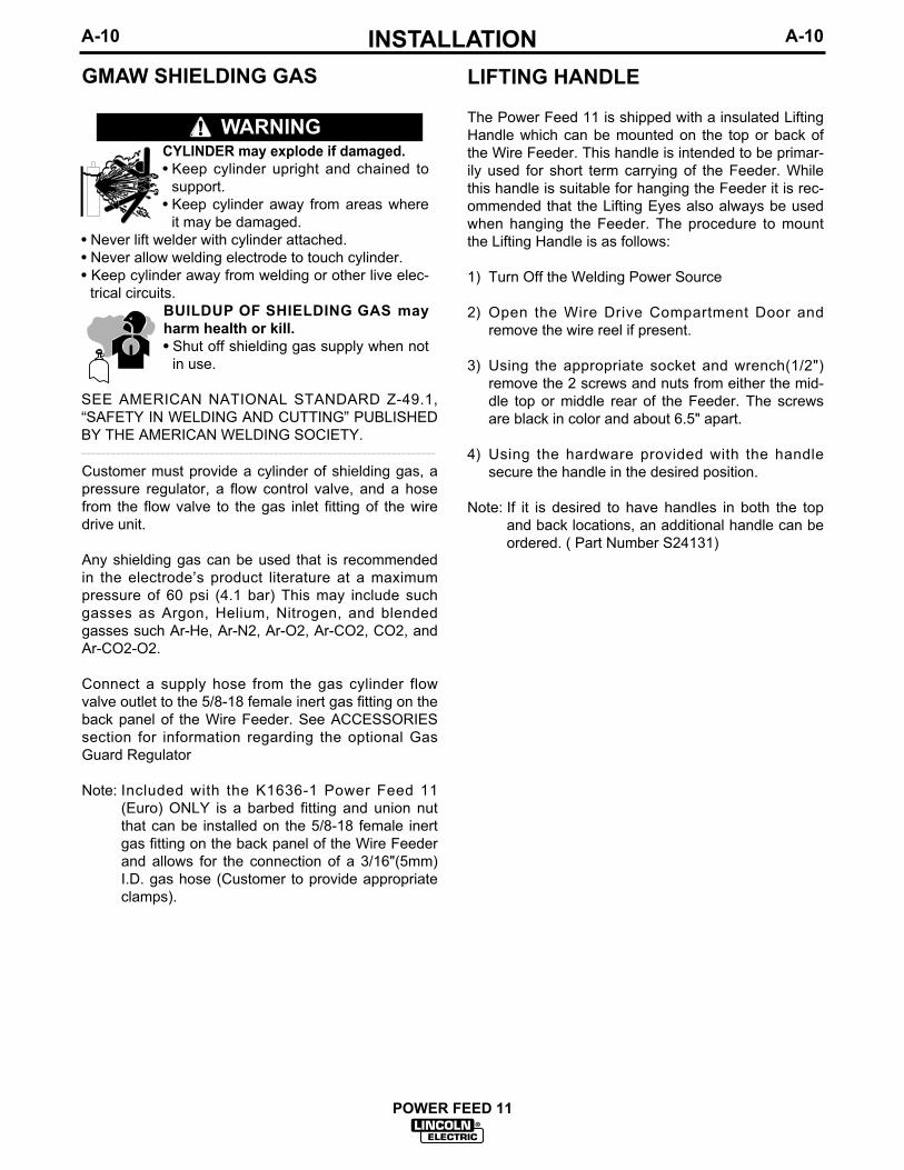
LIFTING HANDLE
The Power Feed 11 is shipped with a insulated LiftingHandle which can be mounted on the top or back ofthe Wire Feeder. This handle is intended to be primar-ily used for short term carrying of the Feeder. Whilethis handle is suitable for hanging the Feeder it is rec-ommended that the Lifting Eyes also always be usedwhen hanging the Feeder. The procedure to mountthe Lifting Handle is as follows:
1) Turn Off the Welding Power Source
2) Open the Wire Drive Compartment Door andremove the wire reel if present.
3) Using the appropriate socket and wrench(1/2")remove the 2 screws and nuts from either the mid-dle top or middle rear of the Feeder. The screwsare black in color and about 6.5" apart.
4) Using the hardware provided with the handlesecure the handle in the desired position.
Note: If it is desired to have handles in both the topand back locations, an additional handle can beordered. ( Part Number S24131)
GMAW SHIELDING GAS
Customer must provide a cylinder of shielding gas, apressure regulator, a flow control valve, and a hosefrom the flow valve to the gas inlet fitting of the wiredrive unit.
Any shielding gas can be used that is recommendedin the electrode’s product literature at a maximumpressure of 60 psi (4.1 bar) This may include suchgasses as Argon, Helium, Nitrogen, and blendedgasses such Ar-He, Ar-N2, Ar-O2, Ar-CO2, CO2, andAr-CO2-O2.
Connect a supply hose from the gas cylinder flowvalve outlet to the 5/8-18 female inert gas fitting on theback panel of the Wire Feeder. See ACCESSORIESsection for information regarding the optional GasGuard Regulator
Note: Included with the K1636-1 Power Feed 11(Euro) ONLY is a barbed fitting and union nutthat can be installed on the 5/8-18 female inertgas fitting on the back panel of the Wire Feederand allows for the connection of a 3/16"(5mm)I.D. gas hose (Customer to provide appropriateclamps).
CYLINDER may explode if damaged.• Keep cylinder upright and chained to
support.• Keep cylinder away from areas where
it may be damaged.• Never lift welder with cylinder attached.• Never allow welding electrode to touch cylinder.• Keep cylinder away from welding or other live elec-
trical circuits.BUILDUP OF SHIELDING GAS mayharm health or kill.• Shut off shielding gas supply when not
in use.
SEE AMERICAN NATIONAL STANDARD Z-49.1,“SAFETY IN WELDING AND CUTTING” PUBLISHEDBY THE AMERICAN WELDING SOCIETY.------------------------------------------------------------------------
WARNING

A-11INSTALLATION
POWER FEED 11
A-11
OPTIONAL FEATURES INSTALLATIONA number of Optional Features are available for
use with Power Feed 11. Some Installation informa-tion is provided in this section, REFER TO THEINSTRUCTIONS THAT COME WITH EACH KIT FORDETAILED INFORMATION REGARDING INSTALLA-TION.
OPTIONAL PANELS FOR CONTROL BOX
All optional panels for the control box are described inthe ACCESSORIES section of this manual along withtheir installation instructions as are all other pieces ofoptional equipment.
The PF-11 Control Box is designed to accept two con-trol panels and one door option. Panels can bemounted in one of two positions: Upper and lower.
Each Control Box is shipped with a Control/Display(CD) panel installed in the upper position, and aCV/Gouge (CV/G) panel in the lower position.
The CD panel must be installed in every Control Box.The remaining panel can be one of the following:CV/G, MX2, or MSP2.
Note: The CD panel must be installed in the upperposition; its harness is not long enough to allowinstallation in the lower position. Similarly,option panels must be installed in the lowerposition.
GENERAL PANEL INSTALLATIONGUIDELINES:
Installation or removal of any panel can be done withonly a Phillips screwdriver after the system power isturned off. To remove a panel, remove the two screwsholding it in place, remove the push-on chassisground wire and remove the harness connection tothe Control Box main PC board. To install any panel,reverse that process. Turn power back on when com-plete (option panels are only recognized at power up.Do not install panels with the power on.) Note thatremoval or installation of any panel may also requirethe removal of the other panel, in order to have easyaccess to the PC board connectors. Detailed installa-tion instructions are shipped with each option panel.

B-1OPERATION
POWER FEED 11
B-1
SAFETY PRECAUTIONS
PRODUCT DESCRIPTION
The Power Feed 11 is a high performance, digitallycontrolled, modular cabinet style wire feeder.Properly equipped, it can support the GMAW, GMAW-P, FCAW, and SMAW processes. The Power Feedwire feeders are designed to be a part of a modular,multi process welding system.
The Power Feed 11 is a 4 driven roll feeder that oper-ates on 40VDC input power.
The Power Feed wire feeders are designed to beused with Power Feed compatible power sources,operating as a system. Each component in the systemhas special circuitry to “talk with” the other systemcomponents, so each component (power source, wirefeeder, electrical accessories) knows what the other isdoing at all times. This shared information lays thegroundwork for a system with superior welding perfor-mance.
The Power Feed 11 is available configured in bothEuropean and World models. There are two featuresthat distinguish the European from the World model.The first is the 4 step trigger logic and the second isthe type of electrode connection which is a Twist-MateTM on the European and a Lug on the World. Seelater in this section for more details on the 4 step trig-ger logic.
RECOMMENDED PROCESSES ANDEQUIPMENT
RECOMMENDED PROCESSES
The Power Feed 11 can be set up in a number of con-figurations. It is designed to be used for GMAW,GMAW-P, FCAW, and SMAW for a variety of materi-als, including mild steel, stainless steel, and coredwires.
RECOMMENDED EQUIPMENT
The Power Feed 11 must be used with power sourceshaving digital communication capabilities and 40 VDCauxiliary power. The presently available power sourceis the PowerWave 455.
DUTY CYCLE
The Power Feed 11 wire feeder is capable of weldingat a 100% duty cycle (continuous welding). The powersource will be the limiting factor in determining systemduty cycle capability.
CONTROL BOX OPERATION
The most frequently used Control Box controls andsettings are external; some features are accessed byinternal controls and settings.
CONTROL BOX PANELS - UPPER PANEL
Control/Display Panel: (Required)
Each PF-11 Control box must have a Control/Display(CD) panel. This panel consists of adjustment knobs,digital displays and a series of indicator lights (LEDs).There are two knobs; each has a 4 digit LED displayand a pair of LEDs associated with it. Knobs and dis-plays have dual functions; the LEDs indicate whichfunction at any given time. This panel also has a dualcolor Status LED, used to indicate the general healthstatus of the Control Box and its connection to othercomponents in the system (power source, wire drive,etc.).
The left knob/display is labeled WFS / AMPS (wirefeed speed/amps). In non-synergic modes, the WFScontrol changes the wire feed speed according to thedesired procedure. In synergic welding modes (syner-gic CV, pulse GMAW) WFS is the dominant controlparameter, controlling all other variables.
Observe all additional Safety Guidelines detailed throughout this manual.
ELECTRIC SHOCK can kill.• Do not touch electrically live parts such
as output terminals or internal wiring.• When inching with gun trigger, electrode and
drive mechanism are “hot” to work andground and could remain energized severalseconds after the gun trigger is released.
• Turn OFF input power at welding powersource before installation or changingdrive roll and/or guide tubes.
• Welding power source must be connectedto system ground per the NationalElectrical Code or any applicable localcodes.
• Only qualified personnel should perform this installation.
WARNING

B-2OPERATIONB-2
The user adjusts WFS according to factors such as weldsize, penetration requirements, heat input, etc. The powersource then uses the WFS setting to adjust its output char-acteristics (output voltage, output current) according to pre-programmed settings contained in the power source. Inconstant current modes (arc gouging, stick, TIG) this controladjusts the output current, in amps. An LED lights to informthe user which function (WFS or amps) is active.This displaycan be either English or metric units. Further, this displaycan be set up to display either WFS or amps when usingwire welding modes. (See SETTING DIP SWITCHES in theINSTALLATION section.)
The right knob is labeled VOLTS / TRIM. In constant volt-age modes (synergic CV, standard CV) the control adjuststhe welding voltage. In pulse synergic welding modes(pulse GMAW only) the user can change the Trim setting toadjust the arc length. It is adjustable from 0.50 to 1.50. ATrim setting of 1.00 means than no adjustments will bemade to the preset arc lengths, and is optimum for mostconditions. An LED lights to inform the user which function(volts or trim) is active.
Both displays indicate preset values, according to the weldmode selected, when not welding. Once welding begins,they switch to displaying actual values. At that time, theindicator LEDs will flash to signify actual values are beingdisplayed. The displays hold the actual values for 5 sec-onds after a weld is stopped. Turning a knob during thehold time shuts off the hold, and returns the meters to theirpreset values.
The allowable settings are determined by other system com-ponents. The WFS range, for instance, is dependent uponthe gear range in the Wire Drive and on the welding pro-grams in the Power Wave power source. The voltage andcurrent are similarly limited by programs in the Power Wave.
Control Box Panels - Lower Panels
A description of the set up controls, Preflow, Run In, ArcControl, Postflow, and Crater, and their maximum and mini-mum values, is in Control Box Panels - Set Up ControlsDescription in this section.
K1542-4 CV/Gouge Panel:(Std.)
The CV/G Panel has a single toggle switch for selectingbetween two weld modes: CV welding and arc gouging. Allother set up parameters, Preflow, Arc Control, Postflow, andCrater, default to zero or off. Run-in defaults to the mini-mum value, or to the weld speed depending on the positionof its associated dip switch. (See “Setting DIP Switches inthe Control Box” section.) Burn back defaults to the on-board trimmer adjustment. When used with the DualProcedure or Memory options, only the WFS/Amps andVolts/Trim settings are saved.
Selecting the Gouge mode immediately energizes theoutput terminals on the power source. The output cur-rent is set by the Amps control. The Volts/Trim adjust-ment has no effect in this mode.
K1542-11 MX2 Panel:(Optional)
This panel provides a selection of four weld modes:CV/MIG, CV/Flux Cored, CC/Stick/soft andCC/Stick/Crisp through a toggle switch and indicatorlights (LEDs). It allows for adjustment of all set up para-meters, Preflow, Run In, Arc Control, Burnback,Postflow, and Crater, through an up/down toggle switch,indicator lights and a 3 digit display.
Weld modes are selected with the Mode Select switch,an up/down center-off momentary toggle switch. Movingthe switch bat up or down moves the Weld Mode LED inthe corresponding direction. Holding the switch in eitherdirection will cause the indicator to move quickly in thecorresponding direction until the switch is released, orthe upper or lower limit is reached.
To adjust Set Up parameters, first select the Set Upparameter for adjustment, and then adjust the displayedvalue up or down.
Set Up parameters are selected with the Select switch,an up/down center-off momentary toggle switch. Movingthe switch bat up or down moves the Weld Mode LED inthe corresponding direction. Holding the switch in eitherdirection will cause the indicator to move quickly in thecorresponding direction until the switch is released, orthe upper or lower limit is reached.
The value of the active Set Up parameter, as defined bythe Set Up LED, is displayed on the MX2 panel Set Updisplay. The value can be modified with the Set switch.The Set switch is an up/down center-off momentary tog-gle switch. Moving the switch bat up or down adjusts thedisplayed value in the corresponding direction. Holdingthe switch in either direction will cause the display tomove quickly in the corresponding direction until theswitch is released, or the upper or lower parameter limitis reached.
To energize the output studs in either CC/Stick mode,the right Control/Display panel knob, labeled Volts/Trim,must be used. The Volts/Trim knob must be turnedclockwise roughly a quarter revolution to energize theoutput studs. (The Volts/trim display will indicate ‘On’when the studs are energized.) Similarly, turning theknob a quarter turn counter-clockwise de-energizes theoutput studs. If a CC/Stick weld mode is entered throughuse of the Dual Procedure, the studs will be in the samestate as when they were last used. If a CC/Stick weldmode is entered through a Memory recall, the studs willbe de-energized.
POWER FEED 11

B-3OPERATIONB-3
K1542-12 MSP2 Panel: (Optional)
This panel provides a selection of over 25 weldmodes, including CV, pulse, FCAW and CC, througha toggle switch and indicator lights (LEDs). It allowsfor adjustment of all set up parameters, Preflow, RunIn, Arc Control, Burnback, Postflow, and Crater,through an up/down toggle switch, indicator lights anda 3 digit display.
To adjust a set up parameter (Weld Mode being oneof those parameters), first select one of the set upparameters for adjustment, and then adjust the dis-played value up or down.
Set up parameters are selected with the Select switch,an up/down center-off momentary toggle switch.Moving the switch bat up or down moves an LED inthe corresponding direction. Holding the switch ineither direction will cause the indicator to move quicklyin the corresponding direction until the switch isreleased, or the upper or lower limit is reached.
The value of the active set up parameter is shown onthe MSP2 panel digital display. The value can bemodified with the Set switch. The Set switch is anup/down center-off momentary toggle switch. Movingthe switch bat up or down adjusts the displayed valuein the corresponding direction. Holding the switch ineither direction will cause the display to move quicklyin the corresponding direction until the switch isreleased, or the upper or lower parameter limit isreached.
To energize the output studs in either CC/Stick mode,the right Control/Display panel knob, labeledVolts/Trim, must be used. The Volts/Trim knob mustbe turned clockwise roughly a quarter revolution toenergize the output studs. (The Volts/trim display willindicate ‘On ’ when the studs are energized.)Similarly, turning the knob a quarter turn counter-clockwise de-energizes the output studs. If a CC/Stickweld mode is entered through use of the DualProcedure, the studs will be in the same state aswhen they were last used. If a CC/Stick weld mode isentered through a Memory recall, the studs will be de-energized.
K1640-1 Dual Procedure / Memory Door Panel:(Optional)
This panel provides two functions: Dual Procedureand Memory. Dual Procedure provides for setting andmanual selection of two procedures. Selection can bedone at the panel, or through a dual procedure weld-ing gun switch connected to the Wire Drive triggerreceptacle. Memory provides six independent storage
locations for Control Box settings. All selections aredone with push buttons and indicator lights. DualProcedure can be used without making use ofMemories; the opposite is also true.
To set Procedure A, hit the Procedure button until theA LED illuminates. Make all desired settings on theControl Box. Settings are automatically saved aschanges are made. Do the same for procedure B. Ifusing a gun switch to select procedures, hit theProcedure button until the Gun LED illuminates.When in the Gun mode is selected, either light A or Bwill be flashing. The flashing light identifies theProcedure, A or B, which is selected by a dual proce-dure gun switch. If no dual procedure switch isplugged in, the Procedure defaults to A. Settings aresaved at power down.
To load a memory, start by setting all adjustments andfunctions on the Power Feed to the desired settings.To save the settings to Memory 1, simply hit the Savebutton (its red light will illuminate) and then hit the 1button. The settings are now saved in Memory 1. Thecontents of Memory 1 will not change, even if thepower is turned off, until the next time the Save keyand the 1 key are hit in sequence. The same proce-dure can be applied to each of the other 5 memories.If the Save key is hit accidentally, simply hit the Savebutton again, its light will go out, and the Save func-tion will be canceled.
Note: It is not required to load all 6 memories at once,nor is it necessary to load them in order. Memory canbe loaded at any time, except when welding.Similarly, the Save key is not active while the gun trig-ger is pulled, or while welding.
Memory has an advanced feature called ‘memoryreminder’. When the Save key is hit, the memoryreminder function flashes the LED of the most recentlyused memory, so the operator can save procedures inthe most recently used memory if desired. It is notnecessary to save to the most recently used memory;the memory reminder function, and it’s flashing LED,can be ignored.
Memories cannot be changed without using the Savekey. When slight procedure adjustments are neces-sary, but there is no desire to ‘permanently’ save theadjustments to a memory, this can be done withProcedure A and Procedure B. Set the Panel to A orB, and recall a memory setting. Make the slight proce-dure adjustment -- it will be saved in A or B, whichev-er was selected when the adjustments were made.The memory location will not have changed.
POWER FEED 11

B-4OPERATIONB-4
To recall a memory setting, simply push that memorybutton. That memory’s contents will be immediatelyrecalled to the Control box.
If the ‘Memory Change with Trigger Pull’ DIP switch ison (see “Setting DIP Switches in the Control Box” sec-tion) it is possible to recall a given memory by quicklypulling and releasing the gun trigger before welding.To switch to memory ‘n’, simply pull and release thegun trigger ‘n’ times without attempting to weld. Thetrigger pulls and releases must be done quickly, inrapid succession. If too much time is allowed to pass,the memory location will not change. Note that when-ever the trigger is pulled, a welding sequence (pre-flow, run in, etc.) begins, so the electrode should notbe allowed to contact the work piece.
CONTROL BOX PANELS -- SET UPCONTROLS DESCRIPTION
Certain large option panels can modify the set upparameters Preflow, Run In, Arc Control, Burnback,Postflow, and Crater. The meaning of those parame-ters, and their maximum and minimum values, follows.
Preflow - Time delay after the trigger is pulled, butbefore weld starts, during which shielding gas flows.Weld start is defined as the time when both the powersource is energized and the Wire Drive begins feedingwire. Adjustable from 0.0 (Off) to 2.5 seconds in 0.1sincrements.
Run In - Wire feed speed during arc starting. WireDrive will feed wire at the Run In speed for one sec-ond, or until weld current flows. Low speed gearrange: Off (Run In speed equals weld wire feedspeed) or adjustable from 50 to 150 IPM (1.25 to 3.80MPM). High speed gear range: Off (Run In speedequals weld wire feed speed) or adjustable from 75 to150 IPM (2.00 to 3.80 MPM)
Arc Control - Unitless characteristic, also known asInductance or Wave Control. Allows operator to varythe arc characteristics from “soft” to “harsh” in all weldmodes. Adjustable from -10.0 to 10.0 in increments of0.1. Off (0.0) is nominal.
Burnback - Time delay after the trigger is releasedduring which the power source remains energized butthe Wire Drive stops feeding wire. Adjustable from0.00 (Off) to 0.25 seconds in 0.01 second increments.
Postflow - Time delay after burnback is complete,during which shielding gas flows. Adjustable from 0.0(Off) to 10.0 seconds in 0.1 second increments.
Crater - Used only when welding with the 4-Step trig-ger mode. Can be set to Off or On. When On,Adjustments can be made to WFS and Volts/Trim onthe Control/Display panel. These settings are thenused for ‘cratering’ when in the 4-Step trigger mode(see explanation of 2 Step and 4 Step operationbelow). When Off, ‘cratering’ is not possible.
CONTROL BOX -- PC BOARD ADJUSTMENTS
The Control Box Mother board provides the capabilityto adjust some wire feeding parameters as follows:
Acceleration: The motor acceleration can be variedin five steps, from slow to fast. See “Setting DIPSwitches in the Control Box” section.
Burnback: For the options which cannot adjust theBurnback set up parameter (CV/G and M panels) aPC board adjustment (trimmer R5) is provided. Therange is 0.0 to 0.25 seconds, increasing in the clock-wise direction. This is ignored by options which havethe ability to adjust Burnback (MX2 and MSP2 pan-els).
Run In: For the options which cannot adjust the RunIn set up parameter (CV/G and M panels) a PC boardDIP switch setting is provided. In one position, the runin speed will be the minimum Wire Drive WFS. At theother setting, run in will occur at the same speed asset on the WFS knob. This DIP switch setting isignored by options which have the ability to adjustRun In (MX2 and MSP2 panels). See “Setting DIPSwitches in the Control Box” section.
POWER FEED 11

B-5OPERATIONB-5
CONTROL BOX -- SETTING OPERATING LIMITS
Upper and lower operating limits can be set for theWFS/Amps setting and the Volts/Trim setting. Doingso requires knowledge of how to set the limits, andaccess to the PC board in the Control Box.
There are two independent sets of limits, Procedure Alimits and Procedure B limits. If a DP/M door option isinstalled, the A and B limits must be set independent-ly. If there is no DP/M door option, the Control Boxdefaults to Procedure A, and only Procedure A limitscan be set.
With system power on, select the weld mode for whichyou want to set limits. If a Dual Procedure option isinstalled, select the procedure A. Turn the systempower off. Remove the two screws holding theControl/Display panel to the Control Box, but do notunplug it. Tilt the panel down to allow access to DIPswitches S1-1, S2-6 and S2-7. (See “Setting DIPSwitches in the Control Box” section.) Do not allowthe panel to hang by the wiring harness.
Determine if the Wire Drive is set up for low or highspeed. If low speed, S1-1 should be off. If high speed,set S1-1 to on.
To adjust the lower limit, set S2-6 to on. Turn thepower on and adjust the WFS/Amps and Volts/Trimknobs to the desired lower limits. Note: You will not beable to adjust the lower limit outside of the minimumand maximum wire feed speed of the Wire Drive, norabove the upper limit. Turn the system power off.Return S2-6 to off.
To adjust the upper limit, set S2-7 to on. Turn thepower on and adjust the WFS/Amps and Volts/Trimknobs to the desired upper limits. Note: You will notbe able to adjust the upper limit outside of the mini-mum and maximum wire feed speed of the WireDrive, nor below the lower limit. Turn the systempower off. Return S2-7 to off.
If a Dual Procedure panel is installed, repeat theabove procedure with the Procedure B selected.When done, attach the Control/Display panel to theControl Box. The machine is now ready for normaloperation with the new limits.
CONTROL BOX -- USING OPERATING LIMITS
Once set, limits apply to all weld modes. LimitingProcedure A to 200 to 300 inches per minute, forexample, limits the ability of the operator to adjust hisWFS in pulse, CV and FCAW weld modes. Limitingthe Volts to 23.0 to 24.5 would limit the ability of theoperator to adjust his Volts in synergic and non-syner-gic CV modes. Procedure B could be set up with dif-ferent limits. Limits are absolute -- they will overridevalues stored in the memories. Note that limits do notapply to set up parameters, such a Preflow and ArcControl.
POWER FEED 11

B-6OPERATIONB-6
WIRE DRIVE OPERATION
The most frequently used Wire Drive settings areexternal; some features are accessed by internal set-tings.
WIRE DRIVE SETTINGS -- EXTERNAL
2 STEP/4 STEP SWITCH:
The Wire Drive has a 2 Step/ 4 Step switch locatednear the gun connector. This switch has no effect inCC modes of operation, such as stick welding.
Europe and World 2 Step Logic:1. Closing the gun trigger initiates the welding
sequence (preflow, run in, etc.).
2. Opening the gun trigger ends the weldingsequence (burnback, postflow, etc.).
World 4 Step Logic:With Crater Fill “OFF”
1. Closing the gun trigger initiates the weldingsequence (preflow, run in, etc.).
2. Opening the trigger after the welding arc is estab-lished allows the weld to continue as long as cur-rent flows. If the arc goes out, the 4 step cycle isreset.
3. Closing the trigger again allows the weld to contin-ue.
4. Opening the trigger again ends the weldingsequence (burnback, postflow, etc.).
With Crater Fill “ON”
1. Closing the gun trigger initiates the weldingsequence (preflow, run in, etc.).
2. Opening the trigger after the welding arc is estab-lished allows the weld to continue as long as cur-rent flows. If the arc goes out, the 4 step cycle isreset.
3. Closing the trigger again changes the wire feedspeed and the Volts/Trim to the Crater values,and the weld to continues
4. Opening the trigger again ends the weldingsequence (burnback, postflow, etc.).
European Only 4 Step LogicWith Crater Fill “OFF”:
1. Closing the gun trigger initiates the weldingsequence (preflow, run in, etc.).
2. Opening the trigger allows the wire to continuefeeding before or after the welding arc is estab-lished. If the arc goes out the wire continues feed-ing.
3. Closing the trigger again cancels the interlock andthe wire to continues feeding.
4. Opening the trigger again ends the weldingsequence (burnback, postflow, etc.).
With Crater Fill “ON”:
1. Closing the gun trigger initiates the weldingsequence (preflow, run in, etc.).
2. Opening the trigger allows the wire to continuefeeding before or after the welding arc is estab-lished. If the arc goes out the wire continues feed-ing.
3. Closing the trigger again cancels the interlockchanges the wire feed speed and the Volts/Trim tothe Crater values, and the wire continues feeding.
4. Opening the trigger again ends the weldingsequence (burnback, postflow, etc.).
COLD FEED / GAS PURGE SWITCH:
The Wire Drive has a Cold Feed/Gas Purge Switchlocated near the gun connector. This is an up/downcenter-off momentary toggle switch.
When held in the up position, the Wire Drive will feedwire, but neither the power source nor the gas sole-noid will be energized. When cold feeding, the feedspeed can be adjusted by rotating the WFS encoderknob on the Control Box. Adjusting the cold feed willnot affect the run in or welding wire feed speed.When the cold feed switch is released, the cold feedvalue is saved.
When this switch is held in the down position, the gassolenoid valve is energized, but neither the powersource nor the drive motor will be energized.
POWER FEED 11

B-7OPERATIONB-7
WIRE DRIVE -- PC BOARD ADJUSTMENTS
ELECTRODE POLARITY:
The system needs to be aware of the electrode polari-ty. A DIP switch setting on the Wire Drive PC board isused for this purpose. See INSTALLATION Section“Setting DIP Switches in the Wire Drive”.
GEAR BOX RATIO:
The systems needs to know which gear has beeninstalled on the Wire Drive, low or high speed. A DIPswitch setting on the Wire Drive PC board is used forthis purpose. See INSTALLATION section“Wire DriveRatio” for information on how to set the DIP Switch.
WIRE REEL LOADING - READI-REELS,SPOOLS OR COILS
To Mount a 30 Lb. (14 kg) Readi-Reel Package(Using the Molded Plastic K363-P Readi-ReelAdapter:)
1. Open the Wire Drive Compartment Door
2. Depress the Release Bar on the Retaining Collar andremove it from the spindle.
3. Place the Adapter on the spindle
4. Re-install the Retaining Collar. Make sure that the ReleaseBar “pops up” and that the collar retainers fully engage theretaining ring groove on the spindle.
5. Rotate the spindle and adapter so the retaining spring is atthe 12 o'clock position.
6. Position the Readi-Reel so that it will rotate in a directionwhen feeding so as to be de- reeled from bottom of thecoil.
7. Set one of the Readi-Reel inside cage wires on the slot inthe retaining spring tab.
8. Lower the Readi-Reel to depress the retaining spring andalign the other inside cage wires with the grooves in themolded adapter.
9. Slide cage all the way onto the adapter until the retainingspring "pops up" fully.
CHECK TO BE SURE THE RETAINING SPRING HASFULLY RETURNED TO THE LOCKING POSITION ANDHAS SECURELY LOCKED THE READI-REEL CAGE INPLACE. RETAINING SPRING MUST REST ON THE CAGE,NOT THE WELDING ELECTRODE.------------------------------------------------------------------------10. To remove Readi-Reel from Adapter, depress retaining
spring tab with thumb while pulling the Readi-Reel cagefrom the molded adapter with both hands. Do not removeadapter from spindle.
FIGURE B.1
To Mount 10 to 44 Lb. (4.5-20 kg) Spools(12"/300 mm Diameter) or 14Lb.(6 Kg)Innershield Coils:
(For 13-14 lb. (6 Kg) Innershield coils, a K435 CoilAdapter must be used).
1. Open the Wire Drive Compartment Door
2. Depress the Release Bar on the Retaining Collarand remove it from the spindle.
3. Place the spool on the spindle making certain thespindle brake pin enters one of the holes in theback side of the spool. Be certain the wire comesoff the reel in a direction so as to de-reel from thebottom of the coil.
4. Re-install the Retaining Collar. Make sure that theRelease Bar “pops up” and that the collar retainersfully engage the retaining ring groove on the spin-dle.
POWER FEED 11
CAUTION

B-8OPERATIONB-8
FEEDING ELECTRODE AND BRAKEADJUSTMENT
1) Turn the Reel or spool until the free end of theelectrode is accessible.
2) While tightly holding the electrode, cut off the bentend and straighten the first 6" (150 mm). Cut offthe first 1" (25 mm). (If the electrode is not proper-ly straightened, it may not feed or may jam causinga "birdnest".)
3) Insert the free end through the incoming guidetube.
4) Press the Cold Inch key or the Cold Feed Modegun trigger and push the electrode into the driveroll.
When feeding with the gun trigger, unless “COLDFEED” trigger mode is selected, the electrode anddrive mechanism are always “HOT” to work andground and could remain “HOT” several seconds afterthe gun trigger is released.___________________________________________
5) Feed the electrode through the gun.
6) Adjust the brake tension with the thumbscrew onthe spindle hub, until the reel turns freely but withlittle or no overrun when wire feeding is stopped.Do not overtighten.
DRIVE ROLL PRESSURE SETTING
The Power Feed 11 pressure is factory pre-set toabout position “2" as shown on the pressure indicatoron the front of the feedplate door. This is an approxi-mate setting.
The optimum drive roll pressure varies with type ofwire, surface condition, lubrication, and hardness.Too much pressure could cause “birdnesting”, but toolittle pressure could cause wire feed slippage withload and/or acceleration. The optimum drive roll set-ting can be determined as follows:
1) Press end of gun against a solid object that iselectrically isolated from the welder output andpress the gun trigger for several seconds.
2) If the wire "birdnests", jams, or breaks at the driveroll, the drive roll pressure is too great. Back thepressure setting out turn, run new wire throughgun, and repeat above steps.
3) If the only result is drive roll slippage, disengagethe gun, pull the gun cable forward about 6" (150mm). There should be a slight waviness in theexposed wire. If there is no waviness, the pres-sure is too low. Increase the pressure settingturn, reconnect the gun, tighten locking clamp andrepeat the above steps.
GAS GUARD REGULATOR SETTING
1) With the gas supply shut off, the Gas Guard regu-lator flow adjusting Key should be set to maximum(full clockwise) which is rated to be 60 SCFH (28l/min).
2) Adjust gas supply flow rate for a level higher thanwill be required, then adjust Gas Guard flowadjusting Key counterclockwise to the desired gasflow rate.
POWER FEED 11
WARNING

B-9OPERATIONB-9
MAKING A WELD
1. Use only a network compatible power source.
2. Properly connect the electrode and work leads forthe correct electrode polarity.
3. Set all desired parameters such as trigger logic,Run-in Speed, Acceleration, Electrode polarity, etc.per “DIP SWITCH SETUP” in the INSTALLATIONsection.
4. Set 2-step, 4-step switch on wire drive to desiredmode of operation. (Refer to “2-step/4-step switchoperation” in this section.)
5. Select Weld Mode. (Refer to Control BoxOperation in this section).
6. Use Control Select switches, increment/decrementswitches, and encoder knobs to set desired para-meters for weld depending on what options areinstalled. (Refer to Control Box Operation in thissection).
7. Feed the electrode through the gun and cable andthen cut the electrode within approximately .38"(9.5 mm) of the end of the contact tip for solid wireand within approximately .75" (19mm) of the exten-sion guide for cored wire.
8. Connect work cable to metal to be welded. Workcable must make good electrical contact to thework. The work must also be grounded as statedin "Arc Welding Safety Precautions".
9. If used, be sure shielding gas valve is turned on.
10. Position electrode over joint. End of electrodemay be lightly touching the work.
11. Lower welding helmet, close gun trigger, and startwelding. Hold the gun so the contact tip to workdistance gives the correct electrical stickout asrequired for the procedure being used.
12. To stop welding, release the gun trigger and thenpull the gun away from the work after the arc goes
out and Postflow time, if used, is over.
13. If required, starting can be optimized by adjustingthe acceleration and/or run-in speed. (Refer toControl Box Operation in this section).
WIRE REEL CHANGING
At the end of a coil, remove the last of the old elec-trode coil from the conductor cable by either pulling itout at the nozzle end of the gun or by using the follow-ing procedure:
1. Cut the end of the electrode off at the gun end. Donot break it off by hand because this puts a slightbend in the wire making it difficult to pull it backthrough the nozzle.
2. Disconnect the gun cable from the gun connectoron the Power Feed 11 wire drive unit and lay thegun and cable out straight.
3. Using pliers to grip the wire, pull it out of the cablefrom the connector end.
4. After the electrode has been removed, reconnectthe gun cable to the drive. Load a new reel of elec-trode per the instructions in “Wire Reel Loading” inthis section.
WIRE FEED OVERLOAD PROTECTION
The wire drive has solid-state overload protection ofthe wire drive motor. If the wire drive motor becomesoverloaded for an extended period of time the wiredrive will issue a shutdown command to the ControlBox and force it’s status light to blink between greenand red. The Control Box turns off the power source,wire feed and gas solenoid. The status light on thewire drive will continue to blink between green and redfor about 30 seconds before the wire drive will auto-matically reset. At that time, the wire drive will issue ashutdown over command to the Control Box that willreturn the system to normal operation. The wire drivewill force it’s status light to solid green.
Overloads can result from improper tip size, liner,drive rolls, or guide tubes, obstructions or bends in thegun cable, feeding wire that is larger than the ratedcapacity of the feeder or any other factors that wouldimpede normal wire feeding. (See “Avoiding WireFeeding Problems” in the MAINTENANCE section).
POWER FEED 11
When using an Open Arc process,it is necessary to use correct eye,head, and body protection.
____________________________________
WARNING

B-10OPERATIONB-10
COMPONENT STATUS LIGHTS
Each network component has a single status light.The light is a bicolor, Green/Red, LED. The purposeof the status light is to allow the operator to quicklyidentify that the system is working properly or, if not,
which component is causing the problem. By usingthe status lights the operator can quickly pinpoint thesystem problem to a particular component. See thefollowing table for a complete listing and description ofall status light conditions.
POWER FEED 11
STATUS LIGHT STATES
NOTE: The green light ON and steady indicates a normal functioning system.
LED State
Off
Green LED blink-ing at a “normal”rate
Red LED blinkingat a “normal” rate
Red/Green LEDblinking at a “nor-mal” rate
Power Source LED
Power Source is not turned ON or is not func-tioning correctly.
It should only blink for a few seconds whilethe system is mapping (identifying compo-nents). If blinking continues every group mayhave a mapping error. (DIP switches may beset incorrectly).
Indicates a recoverable communication fault.The power source should automaticallyrecover: If it cannot recover the LED will besolid red.
Indicates a recoverable hardware fault suchas over temperature, overload shutdown etc.
LED on any other nodes (components);Wire Feeder, Control Box Etc.
The system component is not receiving inputpower or is faulty.
It should only blink for a few seconds untilthe system component (node) has been rec-ognized. If the blinking continues at leastone node in the group has a mapping error(DIP switches may be set incorrectly). Thenode or nodes with mapping errors will beblinking red.• There may be too many components in thegroup. All components in the group will beblinking green.• The power source bus may not be avail-able. The bus may be being used to programanother component.• The LED’s of the power source and thecomponent being programmed will be solidgreen.
Indicates a recoverable communication faultmost likely caused by one of the following.• More than one control box (UI) in thegroup. All control boxes in the group will beblinking red.• No control box (UI) in the group. All nodesin the group will be blinking red.• More than one node, of the same equip-ment type, has the same group and feedhead (FH) numbers. All these nodes will beblinking red.• The feed head DIP switches may be set tozero. The nodes with DIP switches set tozero will be blinking red.•The node bus may be off.
Indicates a recoverable hardware fault suchas over temperature, overload shutdown etc.Could also be an open shutdown circuit atthe feed head (leads 570, 572 with tab termi-nals) typically used for water flow shutdownswitches.

B-11OPERATIONB-11
POWER FEED 11
STATUS LIGHT STATES (CON’T)LED State
Red LED blinkingat a fast rate
Red LED ON andsteady
Green LED ONand steady
Power Source LED
Power source needs to be reprogrammed.Contact your Local Authorized Lincoln FieldService Facility.
Power source has a non-recoverable hard-ware fault. Contact your Local AuthorizedLincoln Field Service Facility.
System normal and functional.
LED on any other nodes (components);Wire Feeder, Control Box Etc.
System component (node) needs to bereprogrammed. Contact your LocalAuthorized Lincoln Field Service Facility.
System component (node) has a non-recov-erable hardware fault. Contact your LocalAuthorized Lincoln Field Service Facility.
System normal and functional.
Normal Blinking LED - Each illumination should exist for 0.5 seconds.Fast Blinking LED - Each illumination should exist for 0.1 seconds.

TABLE C.1 – DRIVE ROLL AND GUIDE TUBE KITS
Wire Size 4-RollDrive
(4-Driven)Solid Steel Electrode
0.023” - 0.025” (0.6 mm) KP1505 - 030S
0.030” (0.8 mm) KP1505 - 030S
0.035” (0.9 mm) KP1505 - 035S
0.040” (1.0 mm) KP1505 - 045S*
0.045” (1.2 mm) KP1505 - 045S*
0.052” (1.4 mm) KP1505 - 052S
1/16” (1.6 mm) KP1505 - 1/16S
5/64” (2.0 mm) KP1505-5/64
3/32” (2.4 mm) KP1505-3/32
Cored Electrode
0.030 (0.8 mm) KP1505 - 035C
0.035” (0.9 mm) KP1505 - 035C
0.040” (1.0 mm) KP1505 - 045C
0.045” (1.2 mm) KP1505 - 045C
0.052” (1.4 mm) KP1505 - 052C
1/16” (1.6 mm) KP1505 - 1/16C
0.068” (1.7 mm) KP1505 - 068
5/64” (2.0 mm) KP1505 - 5/64
3/32” (2.4 mm) KP1505 - 3/32
7/64” Lincore Hard Facing (2.8mm) KP1505 - 7/64H
7/64” (2.8mm) KP1505 - 7/64
.120” (3.0mm) KP1505 - 120
Aluminum Electrode
0.035” (0.9 mm) KP1507 - 035A
0.040” (1.0 mm) KP1507 - 040A
3/64” (1.2 mm) KP1507 - 3/64A
1/16” (1.6 mm) KP1507 - 1/16A
3/32” (2.4 mm) KP1507 - 3/32A
C-1ACCESSORIESC-1
POWER FEED 11
* Included with K1636-1 Power Feed-11 (Europe) only.
The KP1507 series of drive roll kits contain a number of com-ponents, in addition to the drive rolls, to optimize the wirefeeder for aluminum wire feeding. These components arespecifically designed to protect the aluminum wire from abra-sion and deformation, thereby avoiding many common alu-minum feeding problems.

C-2ACCESSORIESC-2
DESCRIPTION OF OPTIONAL CON-TROL BOX PANELS
A number of Optional Features are available for usewith Power Feed 11. Some Installation information isprovided in this section, REFER TO THE INSTRUC-TIONS THAT COME WITH EACH KIT FOR DETAILEDINFORMATION REGARDING INSTALLATION.
OPTIONAL PANELS FOR CONTROL BOX
The PF-11 Control Box is designed to accept two con-trol panels and one door option. Panels can bemounted in one of two positions: Upper and lower.
Each Control Box is shipped with a Control/Display(CD) panel installed in the upper position, and aCV/Gouge (CV/G) panel in the lower position.
The CD panel must be installed in every Control Box.The remaining panel can be one of the following:CV/G, MX2, or MSP2.
Note: The CD panel must be installed in the upperposition; its harness is not long enough to allow instal-lation in the lower position. Similarly, option panelsmust be installed in the lower position.
GENERAL PANEL INSTALLATION GUIDELINES:
Installation or removal of any panel can be done withonly a Phillips screwdriver after the system power isturned off. To remove a panel, remove the two screwsholding it in place, remove the push-on chassisground wire and remove the harness connection tothe Control Box main PC board. To install any panel,reverse that process. Turn power back on when com-plete (option panels are only recognized at power up.Do not install panels with the power on.) Note thatremoval or installation of any panel may also requirethe removal of the other panel, in order to have easyaccess to the PC board connectors. Detailed installa-tion instructions are shipped with each option panel.
K1542-11 “MX2” Panel
This panel provides a selection of four weld modes:CV/MIG, CV/Flux Cored, CC/Stick/soft andCC/Stick/Crisp through a toggle switch and indicatorlights (LEDs). It allows for adjustment of all set upparameters, Preflow, Run In, Arc Control, Burnback,Postflow, and Crater, through an up/down toggleswitch, indicator lights and a 3 digit display.
K1542-12 “MSP2” Panel
This panel provides a selection of over 25 weldmodes, including CV, pulse, FCAW and CC, through atoggle switch and indicator lights (LEDs). It allows foradjustment of all set up parameters, Preflow, Run In,Arc Control, Burnback, Postflow, and Crater, throughan up/down toggle switch, indicator lights and a 3 digitdisplay.
K1640-1 Dual Procedure/ Memory Door Panel
This panel provides two functions: Dual Procedureand Memory. Dual Procedure provides for setting andmanual selection of two procedures. Selection can bedone at the panel, or through a dual procedure weld-ing gun switch connected to the Wire Drive triggerreceptacle. Memory provides six independent storagelocations for Control Box settings. All selections aredone with push buttons and indicator lights.
Installation of the door option can be done with only aPhillips screwdriver and a 3/8” wrench after the sys-tem power is turned off. Start by removing the upperpanel (for access to the PC board connector) and theold door (save the hinge parts). Connect the dooroption PC board connector and the push-on chassisground wire, route the leads through the access hole,and install the door with the original hinge parts.Reinstall the upper panel to complete the installation.Detailed installation instruction are shipped with eachdoor option.
K1543, K1544 AND K1545 INPUTCABLE ASSEMBLIES
Available Cable Assemblies:
K1543 - Control cable only. Consists of a 5-conductorcontrol cable with a 5-pin control cable plug, withoutelectrode cable, and is available in lengths of 8', 16',25', 50' and 100'.
K1544 - Consists of a 5-conductor control cable with a5-pin control cable plug and a 4/0 electrode cable. It israted at 600 amps, 60% duty cycle and is available inlengths of 8', 16', 25', and 50'.
K1545 - Control cable and a 4/0 (85 mm2) electrodecable with Twist-Mate™ connector on one end and astud terminal on the other. It is rated at 500 amps,60% duty cycle and is available in lengths of 8', 16',25', and 50'.
With input power disconnected from the powersource, install the Control Cable Assemblies per theinstruction in INSTALLATION - “Cable Connections”.
POWER FEED 11

C-3ACCESSORIESC-3
WIRE SPINDLE ADAPTERS
K435 - Permits 14 lb. (6 kg) Innershield coils to bemounted on 2" (51 mm) O.D. spindles.
K363P - Adapts Lincoln Readi-Reel coils of electrode30 lb. (14 kg) and 22 lb. (10 kg) to a 2" (51 mm) spin-dle. Durable molded plastic one piece construction.Designed for easy loading; adapter remains on spin-dle for quick changeover.
GUN AND CABLE ASSEMBLIES
A number of Fast-MateTM air cooled and watercooled gun and cable assemblies as well as fumeextraction models are available for use with the PowerFeed 11. See the appropriate Magnum literature fordetailed information.
K1536-1 WATER FLOW SENSOR KIT
This kit is intended to be used as a means of stoppingwire feeding in the event that the water cooler (for awater cooled gun) is not turned on. Water cooled gunscan be damaged very quickly if they are used evenmomentarily without water flowing.
The K1536-1 has two control leads coming from theunit that become electrically common when water isflowing. The .25 inch tab terminals of leads 570 and572, inside the feed head case, are disconnected fromeach other. Then the flow sensor control wires areconnected to leads 570 and 572. Refer to the instruc-tions that come with flow sensor kit for detailed instal-lation instructions.
K659-1 GAS GUARD REGULATOR
Adjustable flow regulator with removable adjuster keyfor CO2 and Argon blend gases. Mounts onto feederinlet, and reduces gas waste and arc start “blow” byreducing surge caused by excess pressure in supplyhose.
Install the 5/8-18 male outlet of the regulator to the5/8-18 female gas inlet on the back panel of the wiredrive. Secure fitting with flow adjuster key at top.Attach gas supply to 5/8-18 female inlet of regulatorper instructions in the INSTALLATION section.
K1649-1 MOUNTING BRACKET-
HORIZONTAL
The K1649-1 provides a bracket for mounting thePower Feed 11 horizontally on top of the PowerSource. Installation instructions are included with thebracket.
POWER FEED 11

D-1MAINTENANCED-1
POWER FEED 11
Avoiding Wire Feeding ProblemsWire feeding problems can be avoided by observingthe following gun handling and feeder set up proce-dures:a) Do not kink or pull cable around sharp corners.
b) Keep the electrode cable as straight as possiblewhen welding or loading electrode through cable.
c) Do not allow dolly wheels or trucks to run overcables.
d) Keep cable clean by following maintenanceinstructions.
e) Use only clean, rust-free electrode. The Lincolnelectrodes have proper surface lubrication.
f) Replace contact tip when the arc starts to becomeunstable or the contact t ip end is fused ordeformed.
g) Do not use excessive wire spindle brake settings.
h) Use proper drive rolls, wire guides and drive rollpressure settings.
Periodic Maintenance
Wire Drive Motor and GearboxEvery year inspect the gearbox and coat the gearteeth with grease. Do not use graphite grease.
Gun and Cable MaintenanceSee appropriate Operator’s Manual.
Procedure for Removing Feedplate fromWire Feeder
1. Using a 3/16" Hex Key Wrench remove the twoscrews that secure the Feedplate to the InterfacePlate. These screws are located just below and tothe right and left of the lower drive gears.
2. Disconnect the Electrode Lead from the Feedplate.
3. Swing the rear of the Feedplate out towards thefront of the machine which will allow it to be pulledback and out of the machine.
4. Remove the gas hose and disconnect the gunleads.
MAINTENANCE
Safety Precautions
Routine Maintenance
Drive Rolls and Guide Tubes
After feeding every coil of wire, inspect the drive rollsection. Clean it as necessary. The drive rolls andInner Wire Guides are stamped with the wire sizesthey will feed. If a wire size other than that stampedon the roll(s) is to be used, the roll(s) and Inner WireGuides must be changed.
All drive rolls have two identical grooves. The rollsmay be flipped over to use the other groove.
See “Procedure to Install Drive Rolls and WireGuides” in the INSTALLATION section for roll chang-ing instructions.
Wire Reel Mounting - Readi-Reels and10 through 44lb (4.5-14kg) Spools
No routine maintenance required.
WARNING
Observe all additional Safety Guidelines detailedthroughout this manual.
ELECTRIC SHOCK can kill.• Do not touch electrically live parts such
as output terminals or internal wiring.• When inching with gun trigger, electrode and
drive mechanism are “hot” to work andground and could remain energized severalseconds after the gun trigger is released.
• Turn OFF input power at welding powersource before installation or changingdrive roll and/or guide tubes.
• Welding power source must be connectedto system ground per the NationalElectrical Code or any applicable localcodes.
• Only qualified personnel should perform maintenance work.

E-1TROUBLESHOOTINGE-1
POWER FEED 11
If for any reason you do not understand the test procedures or are unable to perform the tests/repairs safely, contact yourLocal Lincoln Authorized Field Service Facility for technical troubleshooting assistance before you proceed.
CAUTION
This Troubleshooting Guide is provided tohelp you locate and repair possible machinemalfunctions. Simply follow the three-stepprocedure listed below.
Step 1. LOCATE PROBLEM (SYMPTOM).Look under the column labeled “PROBLEM(SYMPTOMS)”. This column describespossible symptoms that the machine mayexhibit. Find the listing that best describesthe symptom that the machine is exhibiting.
Step 2. POSSIBLE CAUSE.The second column labeled “POSSIBLECAUSE” lists the obvious external possibili-ties that may contribute to the machinesymptom.
Step 3. RECOMMENDED COURSE OFACTIONThis column provides a course of action forthe Possible Cause, generally it states tocontact you local Lincoln Authorized FieldService Facility.
If you do not understand or are unable toperform the Recommended Course ofAction safely, contact you local LincolnAuthorized Field Service Facility.
HOW TO USE TROUBLESHOOTING GUIDE
Service and Repair should only be performed by Lincoln Electric Factory Trained Personnel.Unauthorized repairs performed on this equipment may result in danger to the technician andmachine operator and will invalidate your factory warranty. For your safety and to avoidElectrical Shock, please observe all safety notes and precautions detailed throughout this manual.__________________________________________________________________________
WARNING
WARNING
Observe all additional Safety Guidelines detailedthroughout this manual.
ELECTRIC SHOCK can kill.• Do not touch electrically live parts such
as output terminals or internal wiring.• When inching with gun trigger, electrode and
drive mechanism are “hot” to work andground and could remain energized severalseconds after the gun trigger is released.
• Turn OFF input power at welding powersource before installation or changingdrive roll and/or guide tubes.
• Welding power source must be connectedto system ground per the NationalElectrical Code or any applicable localcodes.
• Only qualified personnel should perform these trouble shooting procedures.

E-2TROUBLESHOOTINGE-2
POWER FEED 11
Observe all Safety Guidelines detailed throughout this manual
If for any reason you do not understand the test procedures or are unable to perform the tests/repairs safely, contact yourLocal Lincoln Authorized Field Service Facility for technical troubleshooting assistance before you proceed.
CAUTION
PROBLEMS(SYMPTOMS) POSSIBLE CAUSE RECOMMENDED
COURSE OF ACTION1. Rough wire feeding or wire not
feeding but drive rolls are turning.a. Gun cable kinked and/or twisted.
b. Wire jammed in gun and cable.Check for mechanical restrictionsin feeding path.
c. Check for current position of driverolls Relative to split wire guidegroove.
d. Drive rolls may not be seatedproperly.
e. Gun cable dirty. - Clean if neces-sary.
f. Worn drive roll.
g. Electrode rusty and/or dirty.Cable frayed, or poor solder jointat work or electrode lug.
h. Worn nozzle or cable l iner. -Replace if necessary.
I. Partially flashed or melted contacttip. - Replace if necessary.
j. Incorrect drive roll pressure. -Readjust if necessary.
k. Improper liner, tip or inner/outerguides. - Replace if necessary.
If all recommended possible areas ofmisadjustment have been checkedand the problem persists, Contactyour local Lincoln AuthorizedField Service Facility.

E-3TROUBLESHOOTINGE-3
POWER FEED 11
Observe all Safety Guidelines detailed throughout this manual
If for any reason you do not understand the test procedures or are unable to perform the tests/repairs safely, contact yourLocal Lincoln Authorized Field Service Facility for technical troubleshooting assistance before you proceed.
CAUTION
PROBLEMS(SYMPTOMS) POSSIBLE CAUSE RECOMMENDED
COURSE OF ACTION2. Variable or “hunting arc.
3. Poor arc striking with sticking or“blast-offs”, weld porosity, narrowand ropy looking bead, or electrodestubbing into plate while welding.
a. Wrong size, worn and/or meltedcontact tip. - Replace if neces-sary.
b. Worn work cable or poor workconnection. - Replace if neces-sary.
c. Loose electrode or work cableconnections.
d. Wrong polarity. - Make sure elec-trode polarity is correct forprocess being used.
e. Gas nozzle extended beyond guntip or wire stickout too long whilewelding.
f. Poor gas shielding on processesrequiring gas. - Check gas flowand mixture.
a. Improper procedures or tech-niques. - See “Gas Metal ArcWelding Guide” (GS-100).
b. Improper gas shielding - Cleangas nozzle. Make certain that gasdiffuser is not empty or turned off.Make certain gas flow rate isproper.
Remove gun liner and check rub-ber seal for any sign of deteriora-tion or damage. Be sure setscrew in connector block is inplace and tightened against theliner bushing.
If all recommended possible areas ofmisadjustment have been checkedand the problem persists, Contactyour local Lincoln AuthorizedField Service Facility.

E-4TROUBLESHOOTINGE-4
POWER FEED 11
Observe all Safety Guidelines detailed throughout this manual
If for any reason you do not understand the test procedures or are unable to perform the tests/repairs safely, contact yourLocal Lincoln Authorized Field Service Facility for technical troubleshooting assistance before you proceed.
CAUTION
PROBLEMS(SYMPTOMS) POSSIBLE CAUSE RECOMMENDED
COURSE OF ACTION4. Tip seizes in diffuser.
5. Unit shuts off while welding orattempting to weld, status light isred/green alternating betweencolors every second. Unit tries torecover after 30 seconds andmay repeat again.
6. Drive roll does not turn althougharc voltage is present, and solenoidis on. Feed head and Control Boxstatus LEDs are both solid green.
a. Tip overheating due to prolongedor excessive high current and/orduty cycle welding.
Note: A light application of hightemperature antiseize lubri-cant (such as Lincoln E2067Graphite Grease) may beapplied to tip of threads.
a. Wire feed shut down circuitmaybe electrically open. (Leads570 and 572 in wire feed head.
b. The wire drive motor may beoverloaded. Check for mechani-cal restrictions in the wire feedingpath.
a. Check for loose or broken leadsat the wire drive motor.
b. Defective wire feed motor or feedhead PC board. Note: With WFSset to max control board shouldsupply 24 VDC to motor (leads#550, #551).
If all recommended possible areas ofmisadjustment have been checkedand the problem persists, Contactyour local Lincoln AuthorizedField Service Facility.
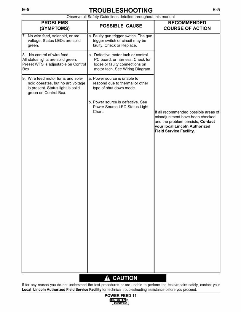
E-5TROUBLESHOOTINGE-5
POWER FEED 11
Observe all Safety Guidelines detailed throughout this manual
If for any reason you do not understand the test procedures or are unable to perform the tests/repairs safely, contact yourLocal Lincoln Authorized Field Service Facility for technical troubleshooting assistance before you proceed.
CAUTION
PROBLEMS(SYMPTOMS) POSSIBLE CAUSE RECOMMENDED
COURSE OF ACTION7. No wire feed, solenoid, or arc
voltage. Status LEDs are solidgreen.
8. No control of wire feed.All status lights are solid green.Preset WFS is adjustable on ControlBox
9. Wire feed motor turns and sole-noid operates, but no arc voltageis present. Status light is solidgreen on Control Box.
a. Faulty gun trigger switch. The guntrigger switch or circuit may befaulty. Check or Replace.
a. Defective motor tach or controlPC board, or harness. Check forloose or faulty connections onmotor tach. See Wiring Diagram.
a. Power source is unable torespond due to thermal or othertype of shut down mode.
b. Power source is defective. SeePower Source LED Status LightChart. If all recommended possible areas of
misadjustment have been checkedand the problem persists, Contactyour local Lincoln AuthorizedField Service Facility.

E-6TROUBLESHOOTINGE-6
POWER FEED 11
Observe all Safety Guidelines detailed throughout this manual
If for any reason you do not understand the test procedures or are unable to perform the tests/repairs safely, contact yourLocal Lincoln Authorized Field Service Facility for technical troubleshooting assistance before you proceed.
CAUTION
PROBLEMS(SYMPTOMS) POSSIBLE CAUSE RECOMMENDED
COURSE OF ACTION10. Speed does not change when
weld current flows. Status lightsare solid green.
11. Voltmeter and/or ammeter donot function properly eventhough status lights are solidgreen. Welding may vary fromnormal procedure.
12. Purge switch on feed head doesnot activate solenoid but triggerclosure in MIG or pulse modesdoes.
13. Cold feed switch does not acti-vate the motor but trigger doesin MIG or Pulse modes. LEDsare solid green on both CB andfeed head boards.
a. Run-in and weld speeds are set tothe same value.
b. Possible problem with currentsensor electronics in powersource. Check power source man-ual to trouble shoot current sensorelectronics.
a. 67 and/or 21 voltage sense leadsmay have intermittent or poor con-nections. Check.
b. Possible problem with powersource electronics.
a. Defective gas purge switch orfeed head board. Check continuitywith gas purge switch held downacross J1 pins 3 and 5. Releasepurge switch and note thereshould be no continuity now. Ifeither of these fail, the problem iseither in the gas purge switch orharnessing. If no failure, replacefeed head board.
a. Defective cold feed switch or feedhead PC board. Check continuitywith cold feed switch held upacross plug pins 3 and 4 of J1.Release the cold inch switch andnote that there should be no conti-nuity now. If either of these fail,the problem is either in the purgeswitch or harnessing. If continuityO.K., replace feed head board.
If all recommended possible areas ofmisadjustment have been checkedand the problem persists, Contactyour local Lincoln AuthorizedField Service Facility.

E-7TROUBLESHOOTINGE-7
POWER FEED 11
Observe all Safety Guidelines detailed throughout this manual
If for any reason you do not understand the test procedures or are unable to perform the tests/repairs safely, contact yourLocal Lincoln Authorized Field Service Facility for technical troubleshooting assistance before you proceed.
CAUTION
PROBLEMS(SYMPTOMS) POSSIBLE CAUSE RECOMMENDED
COURSE OF ACTION14. Displays and/or indicator lights
do not change when their corre-sponding switches and or knobsare activated to request achange.
a. The encoders or switches may befaulty.
b. Check for broken harness wire(s)or harness disconnected fromintended location.
If all recommended possible areas ofmisadjustment have been checkedand the problem persists, Contactyour local Lincoln AuthorizedField Service Facility.

E-8TROUBLESHOOTINGE-8
POWER FEED 11
Observe all Safety Guidelines detailed throughout this manual
If for any reason you do not understand the test procedures or are unable to perform the tests/repairs safely, contact yourLocal Lincoln Authorized Field Service Facility for technical troubleshooting assistance before you proceed.
CAUTION
PROBLEMS(SYMPTOMS) POSSIBLE CAUSE RECOMMENDED
COURSE OF ACTION15. Display(s) are blank.
16. Dual Procedure is not function-ing when using remote dual pro-cedure switch. Status lights aresolid green on CB and headboards.
a. Power source is OFF.
b. Feeder supply or fuse circuit atpower source is blown or tripped,or defective harness or cabling.
c. Display or CB boards may befaulty.
a. Gun has not been selected at thecontrol box. Set dual procedureswitch on CB to gun. Refer tooperating instructions.
b. Faulty remote dual procedureswitch. Remove switch. Checkcontinuity between switch pinswith switch open and closed. If itfails the continuity test, repair orreplace switch.
c. Faulty Local Dual procedureswitch.
If all recommended possible areas ofmisadjustment have been checkedand the problem persists, Contactyour local Lincoln AuthorizedField Service Facility.

E-9TROUBLESHOOTINGE-9
POWER FEED 11
Observe all Safety Guidelines detailed throughout this manual
If for any reason you do not understand the test procedures or are unable to perform the tests/repairs safely, contact yourLocal Lincoln Authorized Field Service Facility for technical troubleshooting assistance before you proceed.
CAUTION
PROBLEMS(SYMPTOMS) POSSIBLE CAUSE RECOMMENDED
COURSE OF ACTION17. Dual Procedure is not function-
ing when using the local dualprocedure switch (on CB).Status lights are solid green onCB and Head boards.
18. Wire feed speed is consistentand adjustable, but operates atthe wrong speed.
19. Status LED not solid green
a. Faulty local dual procedureswitch or CB mother board.Disconnect harness plug from J5of CB mother board. Check thatthere is continuity between plugpins 1 and 7 local DPS is in posi-tion “A” but not when in gun or“B”. Now check that there is con-tinuity between plug pins 1and 8when local DPS is in position “B”but not when in “Gun” or “A”. Ifany of these continuity tests fail,repair or replace switch or switchharness to correct the problem,Otherwise, replace CB motherboard.
a. Dip switch on feed head boarddoes not match gear ratio used atgear box. If using a high speedgear, the feed head PC board dipswitch 8 must be set to 1 or “ON”.
b. Feed head board is not properlyreading DIP switch. Replace feedhead PC board.
a. see LED Status Light Chart.
If all recommended possible areas ofmisadjustment have been checkedand the problem persists, Contactyour local Lincoln AuthorizedField Service Facility.

E-10TROUBLESHOOTINGE-10
POWER FEED 11
Observe all Safety Guidelines detailed throughout this manual
Note: For any Err # listed below write down the error number for reference and try cycling power to see if theerror clears itself. If not, refer to the What to Do column for the given Err.
If for any reason you do not understand the test procedures or are unable to perform the tests/repairs safely, contact yourLocal Lincoln Authorized Field Service Facility for technical troubleshooting assistance before you proceed.
CAUTION
PROBLEMS(SYMPTOMS) POSSIBLE CAUSE RECOMMENDED
COURSE OF ACTIONDisplay shows any of the following:
Err 001
Err 003
Err 004
Err 005
Err 006
More than 1 CB with the same groupnumber.
Too many objects in group.
More than 1 object of the sameequipment type with the same group# and feed head #.
A feed head has its feed head dipswitches set to zero in a group withmore than one object.
Did not receive a recognition com-mand from the power source.
Make sure the group dip switch set-ting is unique for each CB.
A given group can only support up to7 objects. Remove any objects over7 from the group either by changingthe group dip switch settings orphysically disconnecting any objectsover 7 in the group.
Adjust the dip switch setting to makeeither the group # or feed head #unique for all objects of the sameequipment type.
The appropriate feed head # is 1through 7. Check the dip switch set-ting chart in INSTALLATION sectionand set the switches to make theFeed head ID non-zero.
Check to see if the status light is notsolid green on the power source(refer to status light states in OPER-ATION section if not). Also, checkcontinuity in the communication linesfrom CB to Power Source (refer towiring diagram). Refer to Powersource trouble shooting section foradditional information. If all theseavenues fail, replace CB mother PCboard.

E-11TROUBLESHOOTINGE-11
POWER FEED 11
If for any reason you do not understand the test procedures or are unable to perform the tests/repairs safely, contact yourLocal Lincoln Authorized Field Service Facility for technical troubleshooting assistance before you proceed.
CAUTION
Observe all Safety Guidelines detailed throughout this manual
Note: For any Err # listed below write down the error number for reference and try cycling power to see if theerror clears itself. If not, refer to the What to Do column for the given Err.
PROBLEMS(SYMPTOMS) POSSIBLE CAUSE RECOMMENDED
COURSE OF ACTIONDisplay shows any of the following:
Err 020
Err 100
Err 200
Err 201
Err 210
An attempt was made to reprograma CB or feed head but the programdid not verify.
The Power Source issued a shutdown command for some reason.
No Heart beat response from thePS.
No heart beat response from anobject.
EEPROM error.
Check for potential electrical HFnoise generators in the area. Tryremoving the noise source and pro-gramming again. If the Err 020 stilloccurs, either replace the EEPROMchip(s) in the board being repro-grammed or replace the whole PCboard being reprogrammed.
See what to Do on Err 006.
See what to Do on Err 006.
If this occurs while welding, the sta-tus LED should be flashing red onthe object that lost heart beat.Otherwise, look for any nodes thatare flashing green. This indicatesthey have not been recognized andthere is a power source problem(see power source trouble shootingsection). If the status LED is eitherflashing or solid red, there may be aproblem with continuity in the com-munication lines. Check the lines forcontinuity, in the cable and harness-ing (refer to wiring diagram).
Parameter recalled at power up wasout of range. Rotate Encoder Knobto reset. Check all settings beforeproceeding to weld. If this conditionpersists then replace the CB motherPC board.

E-12TROUBLESHOOTINGE-12
POWER FEED 11
If for any reason you do not understand the test procedures or are unable to perform the tests/repairs safely, contact yourLocal Lincoln Authorized Field Service Facility for technical troubleshooting assistance before you proceed.
CAUTION
Observe all Safety Guidelines detailed throughout this manual
Note: For any Err # listed below write down the error number for reference and try cycling power to see if theerror clears itself. If not, refer to the What to Do column for the given Err.
PROBLEMS(SYMPTOMS) POSSIBLE CAUSE RECOMMENDED
COURSE OF ACTIONDisplay shows any of the following:
Err 211
Err 212
- - - (three dashes)
Microprocessor RAM error in ControlBox.
Microprocessor RAM Error in objectboard other than Control Box (Suchas feed head)
Appears on right display of CB mod-ule that contains the status LED
Turn Power off at power source.Wait 5 seconds. Turn power backon. If Err 211 is displayed again,then replace CB mother PC board.
Cycle power as in Err 211. If Err 212is still displayed, then replace the PCboard in the object with the fault. Theobject with the fault should be solidred on its status LED.
This is an indication that a constantcurrent such as stick or gauge modehas been selected. Turning the rightencoder clockwise when in this statewill activate output to Power Source.Turning the right encoder counter-clockwise will deactivate output.

F-1DIAGRAMSF-1
POWER FEED 11
4 5 6
559
512A
512
558
5 6
41
2
512
557
512
557
558
556
558
556
559
6P
11P
13
1
3
A3
4
A12
5
1
6
4
CA
VIT
Y N
UM
BE
RIN
G S
EQ
UE
NC
E (
AS
VIE
WE
D F
RO
M L
EA
D S
IDE
OF
CO
NN
EC
TO
R)
B
2 S
TE
P/
4 S
TE
P
7-20
00
512
B 67A
550
542D500D540D
67A511400
(J2)
67
A B67
= C
HA
SS
IS C
ON
NE
CT
ION
553
550
552551
RE
CT
IFIE
RB
RID
GE
553
540B
541D
AC
+
540540B
-
500
AC
540C
570
SH
UT
571
DO
WN
541A
400A
1 2
GU
N C
ON
NE
CT
OR
(FR
ON
T V
IEW
)
542A
TO
CO
NT
RO
LB
OX
P7
P10
P12
4
500A
A
ON
CO
NT
RO
L P
.C. B
OA
RD
3
**O
N V
OLT
AG
E S
EN
SE
SE
LEC
T P
.C. B
OA
RD
4
540A
*
(P7)
J5**
1
(J7)
7J1**10
**J1 J3 J7 J1
0J1
2
U -
BLU
ER
- R
ED
(J11
)**J2 J6
*
B -
BLA
CK
554
5552
LEA
D C
OLO
R C
OD
ING
1
1
ELE
CT
RIC
AL
SY
MB
OLS
PE
R E
1537
.
3
N.B
. T
OG
GLE
SW
ITC
HE
S S
HO
WN
FR
OM
CO
NN
EC
TIO
N S
IDE
OF
SW
ITC
H.
L
EA
D O
F L
ED
SO
CK
ET
.
GA
SS
OLE
NO
ID
(J4)
554
552
NO
TE
S:
(J1)
4
540A541A541542A542
1
1
(P10
)(J
10)
CO
LD IN
CH
/G
AS
PU
RG
E
67A
(P13
)(J
13)
R67
A
B
VO
LTA
GE
SE
NS
ES
ELE
CT
P.C
. BO
AR
D
R
R.F
.T
OR
OID
1 1 32 3 24
12
42
39
23
21
1110
56
79
8
26
A
A
6
(P11
)
***
A6
A5
J2 J4 J11
J13
4
**
554
1
3 555
A3
12
1
565
500A
45
67
812
12
34
558
555
559560570564
563
571
U56
256
1
565556557
563562561
551
(J2)
511512B
WIR
ING
DIA
GR
AM
- P
OW
ER
FE
ED
11
WIR
E F
EE
DE
R
R.F
.T
OR
OID
2 3 4 2 3
N.B
.
560
N.B
.
512A
8 (J5)
555557
556
554
ON
OFF
S1
RE
D/G
RE
EN
ST
AT
US
LE
DN
.A.
560
559
B
4
560
W
W
CONTROL
564
(P12
)
WIR
ED
RIV
EA
SS
EM
BLY
(J12
)
L107
78
P.C. BOARDG
EA
RB
OX
TA
CH
MO
TO
R
(J3)
512B
1
12
13
56
12
34
10
541D
542D
765
(J6)
(J1)
2
540C
N.A
. P
IN N
EA
RE
ST
TH
E F
LAT
ED
GE
OF
LE
D L
EN
S (
CA
TH
OD
E)
ALI
GN
S W
ITH
BLA
CK
C54
0D
R.F.
TORO
ID
D50
0D
67
E (J9)
67
LIN
C-N
ET
OU
TP
UT
RE
CE
PT
AC
LE(O
PT
ION
AL)
A
67B
540
C
500
D E (J8)
LIN
C-N
ET
INP
UT
RE
CE
PT
AC
LE
INP
UT
ELE
CT
RO
DE
CA
BLE
A
4
35
6
541
542
NO
TE:
This
dia
gram
is fo
r ref
eren
ce o
nly.
It
may
not
be
accu
rate
for a
ll m
achi
nes
cove
red
by th
is m
anua
l. T
he s
peci
fic d
iagr
am fo
r a p
artic
ular
cod
e is
pas
ted
insi
deth
e m
achi
ne o
n on
e of
the
encl
osur
e pa
nels
. If
the
diag
ram
is il
legi
ble,
writ
e to
the
Serv
ice
Dep
artm
ent f
or a
repl
acem
ent.
Giv
e th
e eq
uipm
ent c
ode
num
ber..

F-2DIAGRAMSF-2
POWER FEED 11
63
1 2 3 4
500
7
P.C. BOARD
ENCODER
DUAL
LOWER
1
21
43
43
24 33 421
540A
500A
542A
541A
12
6 21
1
512C
2
500C
555
1
556
553
3
2
554
41
1
56
3
(J1)
N.F.
(J1)
N.F.
N.C.
STATUS LED
RED/GREEN
WB
78
511
560
561
559
562
563
500D
557
500E
558
512A
555
556
553
(J1)
554
N.A.
(J2)
500C
551
512
512C
4
N.B.
N.A.
CABINET
TO FEEDER
OPTION
DOOR PANEL
BOTTOM PANEL
TOP PANEL
65
540A
500A
542A
400A
541A
TOROID
R.F.
B
NOTES:
LEAD OF LED SOCKET.
SIDE DOWN.
N.A. CAVITY NUMBERING SEQUENCE AS VIEWED FROM COMPONENT SIDE OF PC BOARD.
OPTION’S WIRING DIAGRAM FOR ADDITIONAL INFORMATION.
= CHASSIS CONNECTION
N.B. CAVITY NUMBERING SEQUENCE AS VIEWED FROM LEAD SIDE OF CONNECTOR.
ELECTRICAL SYMBOLS PER E1537.
N.C. PIN NEAREST THE FLAT EDGE OF LED LENS (CATHODE) ALIGNS WITH BLACK
B - BLACK
LEAD COLOR CODING
W - WHITE
N.E. THE OPTION INSTALLED MAY NOT HAVE ALL OF THE SHOWN WIRES. SEE THE
N.F. CAVITY NUMBERING SEQUENCE AS VIEWED FROM EDGE OF PC BOARD, COMPONENT
5
512B
6
565
7
564
8 9
500F
10
566
567
568
OPTION
N.E.
569
USER
DISPLAY
P.C. BOARD
OFF
550
552
551
2
MOTHER
1
INTERFACE
WIRING DIAGRAM POWER FEED 11 CONTROL BOX
987654321 10
11
12
13
14 8765431 2 9 10
11
12
(J3)
N.A.
N.A.
(J4)(J5)
N.A.
8
8 6
1
54
512
DOOR
8
S2
ON
PANEL
OPTION
L10833
N.E.
400C
400B
400D
CONTROL BOX
1 8
1 7
7
OFF
500
14
552
550
B W
10
6S1
ON
45
1BOARD
3
(P7)
NO
TE:
This
dia
gram
is fo
r ref
eren
ce o
nly.
It
may
not
be
accu
rate
for a
ll m
achi
nes
cove
red
by th
is m
anua
l. T
he s
peci
fic d
iagr
am fo
r a p
artic
ular
cod
e is
pas
ted
insi
deth
e m
achi
ne o
n on
e of
the
encl
osur
e pa
nels
. If
the
diag
ram
is il
legi
ble,
writ
e to
the
Serv
ice
Dep
artm
ent f
or a
repl
acem
ent.
Giv
e th
e eq
uipm
ent c
ode
num
ber..
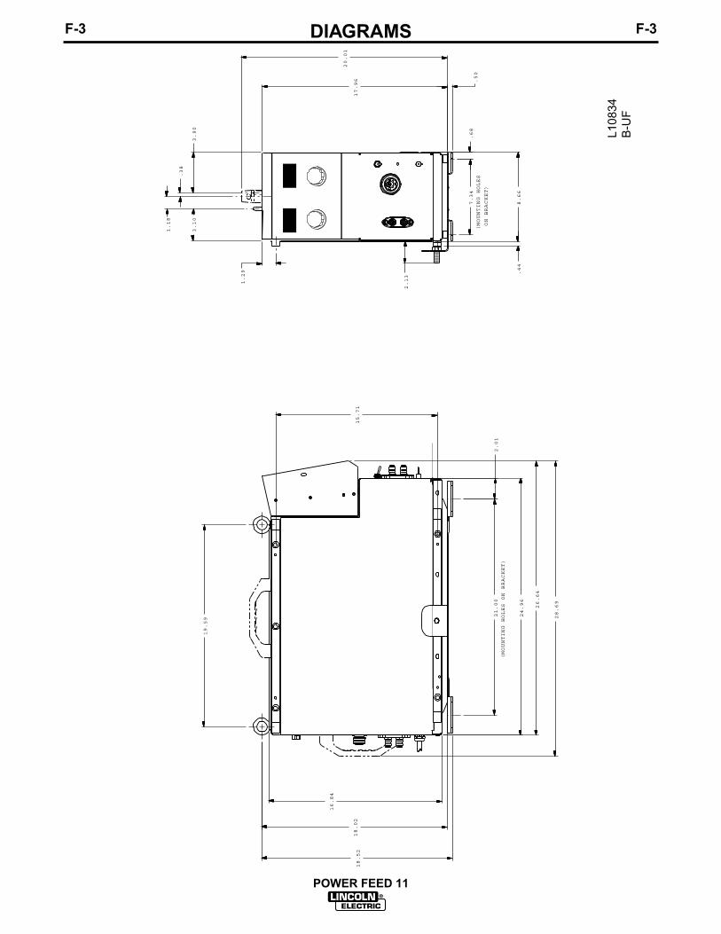
F-3DIAGRAMSF-3
POWER FEED 11
1.29
2.01
8.66
2.13
(MOUNTING HOLES
ON BRACKET)
7.34
.38
3.90
3.10
15.71
17.96
.68
1.18
19.59
16.84
28.69
18.02
18.52
.44
20.01
.50
21.00
(MOUNTING HOLES ON BRACKET)
24.96
26.64
L108
34B
-UF

NOTES
POWER FEED 11

Now Available...12th EditionThe Procedure Handbook of Arc Welding
With over 500,000 copies of previous editions publishedsince 1933, the Procedure Handbook is considered by many to be the “Bible” of the arc welding industry.
This printing wil l go fast so don ’t delay. Place your order now using the coupon below.
The hardbound book contains over 750 pages of weldinginformation, techniques and procedures. Much of this material has never been included in any other book.
A must for al l welders, supervisors, engineers anddesigners. Many welding instructors will want to use the bookas a reference for all students by taking advantage of the lowquantity discount prices which include shipping by4th class parcel post.
$15.00 postage paid U.S.A. Mainland
How To Read Shop Drawings
The book contains the latest information and applicationdata on the American Welding Society Standard WeldingSymbols. Detailed discussion tells how engineers anddraftsmen use the “short-cut” language of symbols to passon assembly and welding information to shop personnel.
Practical exercises and examples develop the reader’s abilityto visualize mechanically drawn objects as they will appearin their assembled form.
187 pages with more than 100 illustrations. Size 8-1/2” x 11”Durable, cloth-covered board binding.
$4.50 postage paid U.S.A. Mainland
New Lessons in Arc WeldingLessons, simply written, cover manipulatory techniques;
machine and electrode characteristics; related subjects,such as distortion; and supplemental information on arcwelding applications, speeds and costs. Practice materials,exercises, questions and answers are suggested for each lesson.
528 pages, well illustrated, 6” x 9” size, bound in simulated,gold embossed leather.
$5.00 postage paid U.S.A. Mainland
Need Welding Training?The Lincoln Electric Company operates the oldest and
most respected Arc Welding School in the United States at itscorporate headquarters in Cleveland, Ohio. Over 100,000 stu-dents have graduated. Tuit ion is low and the training is “hands on”
For details write: Lincoln Welding School22801 St. Clair Ave. Cleveland, Ohio 44117-1199.
and ask for bulletin ED-80 or call 216-383-2259 and ask for theWelding School Registrar.
Lincoln Welding SchoolBASIC COURSE $700.00
5 weeks of fundamentalsThere is a 10% discount on all orders of $50.00 or more for shipment at one time to one location.Orders of $50 or less before discount or orders outside of North America must be prepaid with charge, check or money order in U.S. Funds Only.Prices include shipment by 4 thClass Book Rate for U.S.A. Mainland Only. Please allow up to 4 weeks for delivery.UPS Shipping for North America Only. All prepaid orders that request UPS shipment please add:
$5.00 For order value up to $49.99$10.00 For order value between $50.00 & $99.99$15.00 For order value between $100.00 & $149.00
For North America invoiced orders over $50.00 & credit card orders, if UPS is requested, it will be invoiced or charged to you at cost.Outside U.S.A. Mainland order must be prepaid in U.S. Funds. Please add $2.00 per book for surface mail or $15.00 per book for air parcel post shipment.METHOD OF PAYMENT: (Sorry, No C.O.D. Orders)
CHECK ONE:Name: _______________________________________________
Please Invoice (only if order is over $50.00)Address: _______________________________________________
Check or Money Order Enclosed, U.S. Funds only _______________________________________________
Credit Card - Telephone: _______________________________________________
Signature as it appears on Charge Card:Account No. |_|_|_|_|_|_|_|_|_|_|_|_|_|_|_|_|_|_|_|_|_| Exp Date |_|_| |_|_| ______________________Month Year
USE THIS FORM TO ORDER: Order from: BOOK DIVISION, The Lincoln Electric Company, 22801 St. Clair Avenue, Cleveland, Ohio 44117-1199BOOKS OR FREE INFORMATIVE CATALOGS Telephone: 216-383-2211 or, for fastest service, FAX this completed form to: 216-361-5901.
Lincoln Welding School Titles: Price Code Quantity Cost(ED-80) New Lessons in Arc Welding $5.00 L
Seminar Information Procedure Handbook “Twelfth Edition” $15.00 PH(ED-45) How to Read Shop Drawings $4.50 H
Educational Video Information Incentive Management $5.00 IM(ED-93) A New Approach to Industrial Economics $5.00 NA
James F. Lincoln Arc Welding The American Century of John C. Lincoln $5.00 ACFoundation Book Information Welding Preheat Calculator $3.00 WC-8
(JFLF-515) Pipe Welding Charts $4.50 ED-89SUB TOTAL
Additional Shipping Costs if anyTOTAL COST
MasterCard
VISA ®
AMERICAN EXPRESS
MasterCardMasterCard®
AMERICAN EXPRESS

WARNING
AVISO DEPRECAUCION
ATTENTION
WARNUNG
ATENÇÃO
Spanish
French
German
Portuguese
Japanese
Chinese
Korean
Arabic
LEIA E COMPREENDA AS INSTRUÇÕES DO FABRICANTE PARA ESTE EQUIPAMENTO E AS PARTES DE USO, E SIGA ASPRÁTICAS DE SEGURANÇA DO EMPREGADOR.
● Keep your head out of fumes.● Use ventilation or exhaust to
remove fumes from breathing zone.
● Los humos fuera de la zona de res-piración.
● Mantenga la cabeza fuera de loshumos. Utilice ventilación oaspiración para gases.
● Gardez la tête à l’écart des fumées.● Utilisez un ventilateur ou un aspira-
teur pour ôter les fumées des zonesde travail.
● Vermeiden Sie das Einatmen vonSchweibrauch!
● Sorgen Sie für gute Be- undEntlüftung des Arbeitsplatzes!
● Mantenha seu rosto da fumaça.● Use ventilação e exhaustão para
remover fumo da zona respiratória.
● Turn power off before servicing.
● Desconectar el cable de ali-mentación de poder de la máquinaantes de iniciar cualquier servicio.
● Débranchez le courant avant l’entre-tien.
● Strom vor Wartungsarbeitenabschalten! (Netzstrom völlig öff-nen; Maschine anhalten!)
● Não opere com as tampas removidas.● Desligue a corrente antes de fazer
serviço.● Não toque as partes elétricas nuas.
● Do not operate with panel open orguards off.
● No operar con panel abierto oguardas quitadas.
● N’opérez pas avec les panneauxouverts ou avec les dispositifs deprotection enlevés.
● Anlage nie ohne Schutzgehäuseoder Innenschutzverkleidung inBetrieb setzen!
● Mantenha-se afastado das partesmoventes.
● Não opere com os paineis abertosou guardas removidas.

WARNING
AVISO DEPRECAUCION
ATTENTION
WARNUNG
ATENÇÃO
Spanish
French
German
Portuguese
Japanese
Chinese
Korean
Arabic
READ AND UNDERSTAND THE MANUFACTURER’S INSTRUCTION FOR THIS EQUIPMENT AND THE CONSUMABLES TO BEUSED AND FOLLOW YOUR EMPLOYER’S SAFETY PRACTICES.
SE RECOMIENDA LEER Y ENTENDER LAS INSTRUCCIONES DEL FABRICANTE PARA EL USO DE ESTE EQUIPO Y LOSCONSUMIBLES QUE VA A UTILIZAR, SIGA LAS MEDIDAS DE SEGURIDAD DE SU SUPERVISOR.
LISEZ ET COMPRENEZ LES INSTRUCTIONS DU FABRICANT EN CE QUI REGARDE CET EQUIPMENT ET LES PRODUITS AETRE EMPLOYES ET SUIVEZ LES PROCEDURES DE SECURITE DE VOTRE EMPLOYEUR.
LESEN SIE UND BEFOLGEN SIE DIE BETRIEBSANLEITUNG DER ANLAGE UND DEN ELEKTRODENEINSATZ DES HER-STELLERS. DIE UNFALLVERHÜTUNGSVORSCHRIFTEN DES ARBEITGEBERS SIND EBENFALLS ZU BEACHTEN.
● Do not touch electrically live parts orelectrode with skin or wet clothing.
● Insulate yourself from work andground.
● No toque las partes o los electrodosbajo carga con la piel o ropa moja-da.
● Aislese del trabajo y de la tierra.
● Ne laissez ni la peau ni des vête-ments mouillés entrer en contactavec des pièces sous tension.
● Isolez-vous du travail et de la terre.
● Berühren Sie keine stromführendenTeile oder Elektroden mit IhremKörper oder feuchter Kleidung!
● Isolieren Sie sich von denElektroden und dem Erdboden!
● Não toque partes elétricas e elec-trodos com a pele ou roupa molha-da.
● Isole-se da peça e terra.
● Keep flammable materials away.
● Mantenga el material combustiblefuera del área de trabajo.
● Gardez à l’écart de tout matérielinflammable.
● Entfernen Sie brennbarres Material!
● Mantenha inflamáveis bem guarda-dos.
● Wear eye, ear and body protection.
● Protéjase los ojos, los oídos y elcuerpo.
● Protégez vos yeux, vos oreilles etvotre corps.
● Tragen Sie Augen-, Ohren- und Kör-perschutz!
● Use proteção para a vista, ouvido ecorpo.

• Sales and Service through Subsidiaries and Distributors Worldwide •Cleveland, Ohio 44117-1199 U.S.A. TEL: 216.481.8100 FAX: 216.486.1751 WEB SITE: www.lincolnelectric.com
• World's Leader in Welding and Cutting Products •