power factor and harmonics primer - cm...
TRANSCRIPT
Your Tailored Power Solutions ProviderTMwww.stacoenergy.com
Power Factor and Harmonics Primer
www.stacoenergy.comPHC-HFC Primer
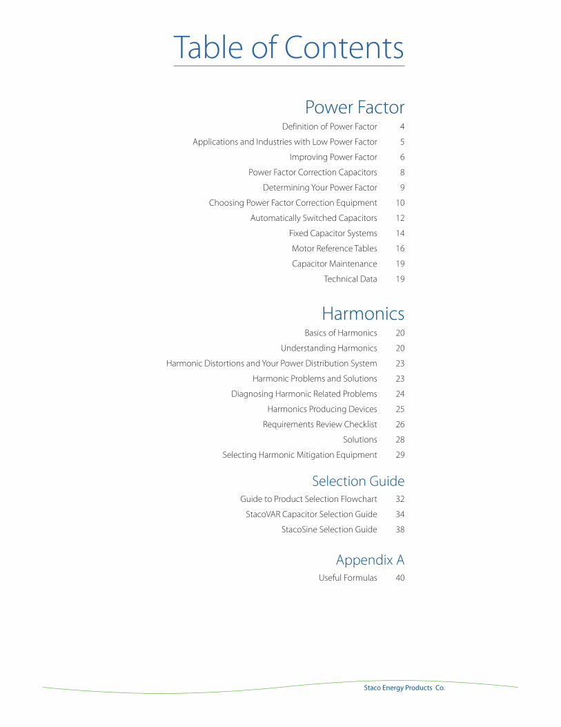
Power Factor Definition of Power Factor 4
Applications and Industries with Low Power Factor 5
Improving Power Factor 6
Power Factor Correction Capacitors 8
Determining Your Power Factor 9
Choosing Power Factor Correction Equipment 10
Automatically Switched Capacitors 12
Fixed Capacitor Systems 14
Motor Reference Tables 16
Capacitor Maintenance 19
Technical Data 19
Harmonics Basics of Harmonics 20
Understanding Harmonics 20
Harmonic Distortions and Your Power Distribution System 23
Harmonic Problems and Solutions 23
Diagnosing Harmonic Related Problems 24
Harmonics Producing Devices 25
Requirements Review Checklist 26
Solutions 28
Selecting Harmonic Mitigation Equipment 29
Selection Guide Guide to Product Selection Flowchart 32
StacoVAR Capacitor Selection Guide 34
StacoSine Selection Guide 38
Appendix A Useful Formulas 40
Table of Contents
Staco Energy Products Co.
www.stacoenergy.comPFC-HFC Primer
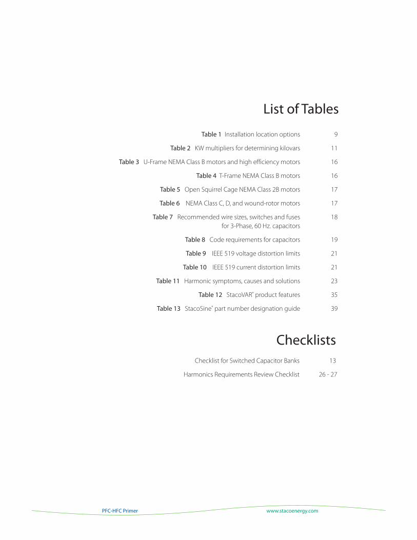
List of Tables
Table 1 Installation location options 9
Table 2 KW multipliers for determining kilovars 11
Table 3 U-Frame NEMA Class B motors and high efficiency motors 16
Table 4 T-Frame NEMA Class B motors 16
Table 5 Open Squirrel Cage NEMA Class 2B motors 17
Table 6 NEMA Class C, D, and wound-rotor motors 17
Table 7 Recommended wire sizes, switches and fuses 18
for 3-Phase, 60 Hz. capacitors
Table 8 Code requirements for capacitors 19
Table 9 IEEE 519 voltage distortion limits 21
Table 10 IEEE 519 current distortion limits 21
Table 11 Harmonic symptoms, causes and solutions 23
Table 12 StacoVAR® product features 35
Table 13 StacoSine® part number designation guide 39
Checklists Checklist for Switched Capacitor Banks 13
Harmonics Requirements Review Checklist 26 - 27
3
Staco Energy Products Co.
List of Figures Figure 1 A power triangle shows the relationship between KW, KVA and KVAR 4
Figure 2 Power triangle before and after capacitor installation 7
Figure 3 Installing capacitors online 10
Figure 4 Locating capacitors on motor circuits 14
Figure 5 - 9 Locating capacitors on reduced voltage & multi-speed motors 15
Figure 10 Fundamental sinewave compared to the 5th order harmonic wave 20
Figure 11 Sinewave with 5th order harmonic present 20
Figure 12 Harmonics from a 6-pulse rectifier (UPS system) 25
Figure 13 Passive capacitor bank harmonic filter installation 29
Figure 14 Compensating sinewave generated by an active harmonic filter 30
4
Power Factor Correction
www.stacoenergy.comPFC-HFC Primer
Definition of Power Factor
Power Factor (PF) is a term used in regard to the
efficiency of an electrical power distribution system. Also
known as displacement power factor, power factor is a
measurement between the current and voltage phase
shift waveforms.
Power factor consists of three components: KW, which
is the working, or real, power; KVA, which is called the
apparent power; and KVAR, or reactive power. KW
does the actual work, whereas KVAR does not do any
beneficial work. The measurement of the relationship
between KW and KVAR is the KVA. Reactive power is
measured in volt-amperes reactive (VAR), also known as
KVAR when the number exceeds 1,000.
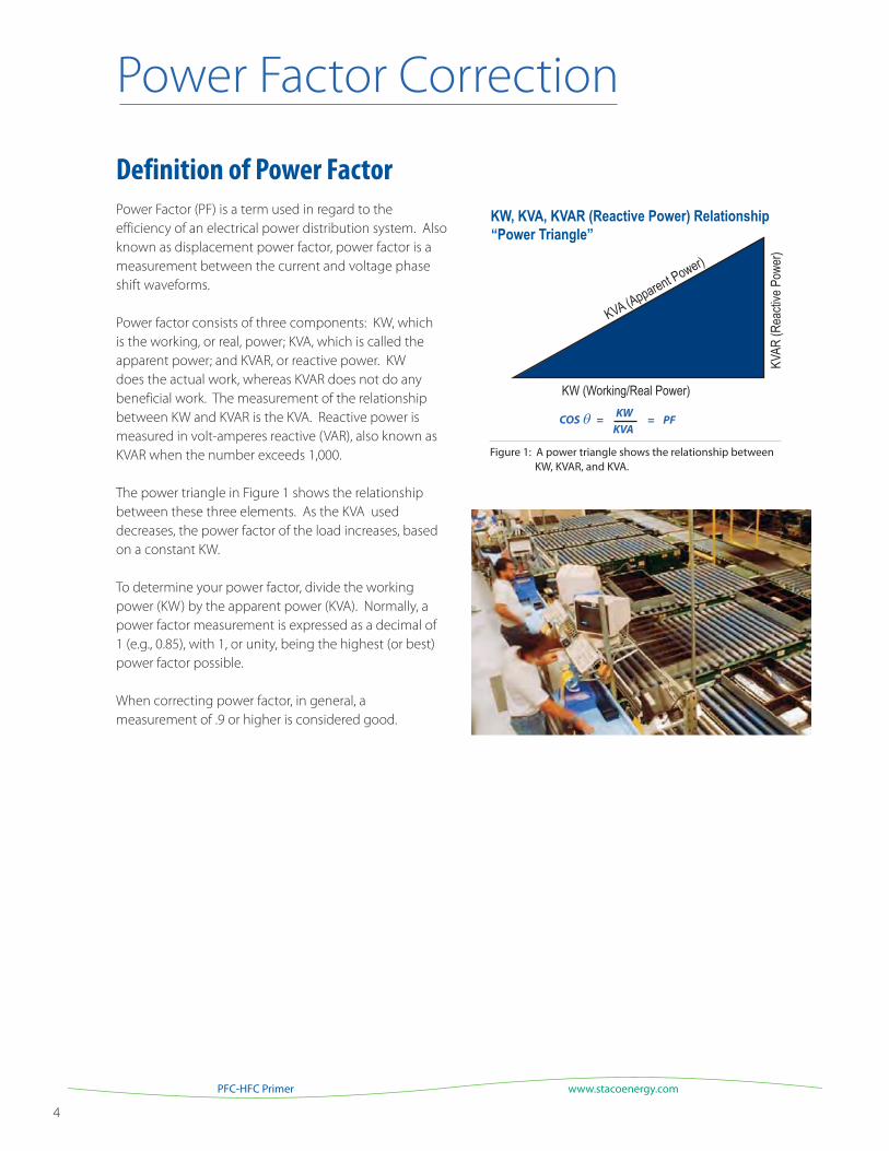
The power triangle in Figure 1 shows the relationship
between these three elements. As the KVA used
decreases, the power factor of the load increases, based
on a constant KW.
To determine your power factor, divide the working
power (KW) by the apparent power (KVA). Normally, a
power factor measurement is expressed as a decimal of
1 (e.g., 0.85), with 1, or unity, being the highest (or best)
power factor possible.
When correcting power factor, in general, a
measurement of .9 or higher is considered good.
Figure 1: A power triangle shows the relationship between KW, KVAR, and KVA.
KW
KVACOS θ = = PF
Power Factor Correction
5
Staco Energy Products Co.
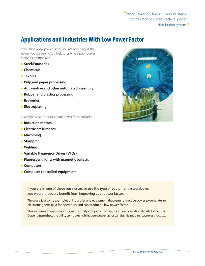
If you have a low power factor, you are not using all the
power you are paying for. Industries where poor power
factor is common are:
Steel/Foundries
Chemicals
Textiles
Pulp and paper processing
Automotive and other automated assembly
Rubber and plastics processing
Breweries
Electroplating
Load types that can cause poor power factor include:
Induction motors
Electric arc furnaces
Machining
Stamping
Welding
Variable Frequency Drives (VFDs)
Fluorescent lights with magnetic ballasts
Computers
Computer controlled equipment
Applications and Industries With Low Power Factor
If you are in one of these businesses, or use the type of equipment listed above, you would probably benefit from improving your power factor.
These are just some examples of industries and equipment that require reactive power to generate an electromagnetic field for operation, and can produce a low power factor.
This increases operational costs, as the utility company transfers its excess operational costs to the user. Depending on how the utility computes its bills, poor power factor can significantly increase electric costs.
“Power factor (PF) is a term used in regard
to the efficiency of an electrical power
distribution system.”
6
Power Factor Correction
www.stacoenergy.comPFC-HFC Primer
Power Factor Improvement Examples:
Improving your power factor increases the capacity of your electrical system:
Assume you have a load of 100 KVA. If your existing power
factor is .80, then you have enough power to light eight
hundred 100-watt light bulbs. If you improve your power
factor to .95, then you will have enough power to light nine
hundred and fifty 100-watt light bulbs. Figure 2 shows the ef-
fect that power factor improvement has on a power triangle.
Improving your power factor can save you money:
No matter how your utility bills for electric consumption, you
can save money by installing power factor correction capaci-
tors, because you will use less energy, lengthen the life of
your existing equipment and reduce electrical requirements
for any new or future equipment that you install.
KVA Billing
If your utility uses KVA billing, you are charged for the current
you draw from the grid. By improving your power factor
rating, you will pull less current. Your charges will be lower, to
more closely align with the actual amount of power you are
using.
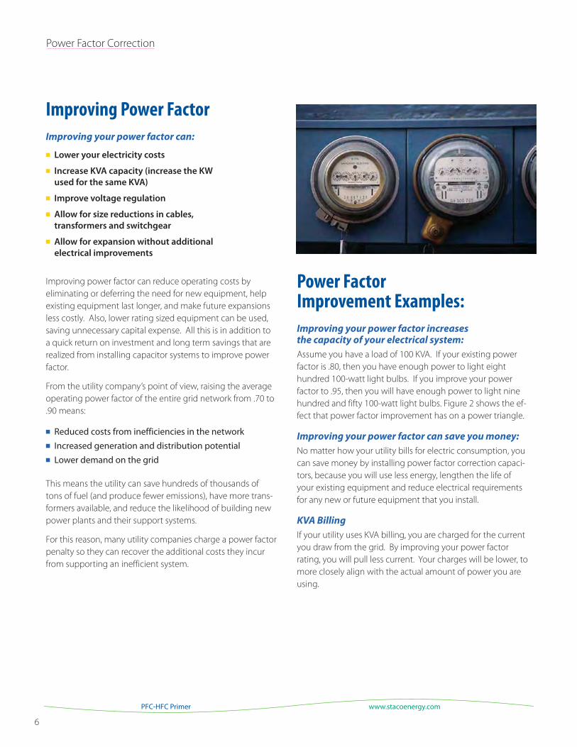
Improving Power Factor
Improving your power factor can:
Lower your electricity costs
Increase KVA capacity (increase the KW
used for the same KVA)
Improve voltage regulation
Allow for size reductions in cables,
transformers and switchgear
Allow for expansion without additional
electrical improvements
Improving power factor can reduce operating costs by
eliminating or deferring the need for new equipment, help
existing equipment last longer, and make future expansions
less costly. Also, lower rating sized equipment can be used,
saving unnecessary capital expense. All this is in addition to
a quick return on investment and long term savings that are
realized from installing capacitor systems to improve power
factor.
From the utility company’s point of view, raising the average
operating power factor of the entire grid network from .70 to
.90 means:
Reduced costs from inefficiencies in the network Increased generation and distribution potential
Lower demand on the grid
This means the utility can save hundreds of thousands of
tons of fuel (and produce fewer emissions), have more trans-
formers available, and reduce the likelihood of building new
power plants and their support systems.
For this reason, many utility companies charge a power factor
penalty so they can recover the additional costs they incur
from supporting an inefficient system.
7
Staco Energy Products Co.
“Depending upon how your utility bills for electric
consumption, you will save money by installing
power factor correction capacitors.”
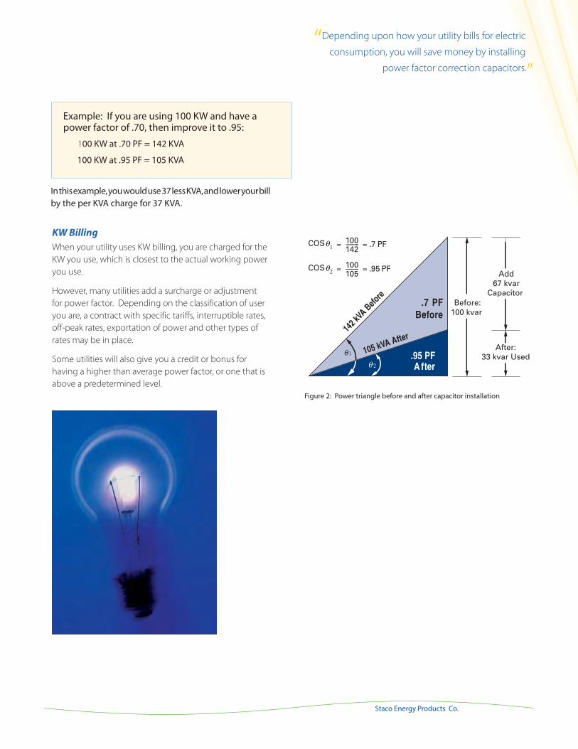
Example: If you are using 100 KW and have a power factor of .70, then improve it to .95:
100 KW at .70 PF = 142 KVA
100 KW at .95 PF = 105 KVA
KW Billing
When your utility uses KW billing, you are charged for the
KW you use, which is closest to the actual working power
you use.
However, many utilities add a surcharge or adjustment
for power factor. Depending on the classification of user
you are, a contract with specific tariffs, interruptible rates,
off-peak rates, exportation of power and other types of
rates may be in place.
Some utilities will also give you a credit or bonus for
having a higher than average power factor, or one that is
above a predetermined level.
Figure 2: Power triangle before and after capacitor installation
In this example, you would use 37 less KVA, and lower your bill by the per KVA charge for 37 KVA.
8
Power Factor Correction
www.stacoenergy.comPFC-HFC Primer
Return on Investment Example:
Using the previous example, where KVA is the primary billing
component, if you are billed $11.22 per KVA:
100 KW at .70 PF = 142 KVA, or $1,593100 KW at .95 PF = 105 KVA, or $1,178
This represents a monthly savings of $415, or $4,980 annually.
If you assume an equipment cost of $5,600 (not including
installation), this example shows an ROI of about 14 months.
After the payback period, there can be an ongoing 26%
savings for this customer.
This is just one example of how to calculate your savings,
and each situation will have unique variables to consider.
However, a 12 – 18 month ROI is considered average.
Power Factor Correction CapacitorsA capacitor’s function is to provide kilovars to a system at the
point where it is connected. Capacitors improve power factor,
reduce lagging components on the circuit, reduce power
losses, and reduce KVA load. By using capacitors, the power
system becomes more efficient. Capacitors provide reactive
power to replace the VARs wasted by an inefficient load.
Capacitor systems generally are the most economical means of improving power factor because of their:
Relative Low Cost Easy Installation Minimal Maintenance High Efficiency and Low Losses
The capacitor requirements of each user will vary widely. Low
voltage class systems, such as those offered by Staco Energy
Products Co., are available as everything from off-the-shelf
components to highly unique, specially designed power
systems.
9
Staco Energy Products Co.
Determining Your Power Factor
A review of the previous twelve months utility bills will help
to evaluate power factor and demand usage. Monitoring at
the incoming service entrance or at specific loads can help
identify problems within a facility. Monitoring equipment
may include powermeters, which offer a wide range of
measurements and can supply a great deal of information
about a suspect load.
More detailed power factor determinations can be found
through a facility review by a power analyst. Some utility
companies offer analysis, or have a referral program
for businesses wanting to improve their efficiency. Also,
Staco Energy Products Co. has partnerships with many
independent consultants throughout the country who can
provide this service for you.
Types of Capacitor Systems
Simple, small fixed capacitors can be installed at single
motor locations. Larger fixed assemblies can be installed
to work with more than one motor. Still larger automatic
switched capacitor systems can be installed for a large
sector of a facility, or at the service entrance, to help correct
the power factor of an entire facility.
Capacitor systems may be integrated with switchgear,
retrofitted, or installed in a match-and-line arrangement.
Detuned capacitors with iron-core reactors are used when
harmonics may become a problem. Although capacitors
do not create harmonics, they can amplify existing har-
monics if they are not de-tuned. Harmonics are discussed
in-depth later in this booklet.
Table 1. Installation location options.
Installation Location Cost Benefit Flexibility
At Motor Low Acceptable Minimal
At Feeders Medium Good Better
At Service Entrance Highest Best Maximum
“Capacitor systems may be integrated with
switchgear, retrofitted, or installed
in a match-and-line arrangement.”
10
Power Factor Correction
www.stacoenergy.comPFC-HFC Primer
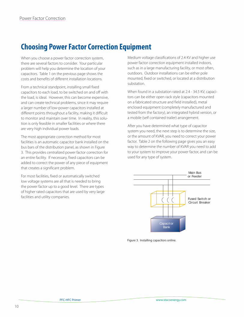
CapacitorBank
Fused Switch orCircuit Breaker
Main Busor Feeder
Figure 3. Installing capacitors online.
When you choose a power factor correction system,
there are several factors to consider. Your particular
problem will help you determine the location of your
capacitors. Table 1 on the previous page shows the
costs and benefits of different installation locations.
From a technical standpoint, installing small fixed
capacitors to each load, to be switched on and off with
the load, is ideal. However, this can become expensive,
and can create technical problems, since it may require
a larger number of low-power capacitors installed at
different points throughout a facility, making it difficult
to monitor and maintain over time. In reality, this solu-
tion is only feasible in smaller facilities or where there
are very high individual power loads.
The most appropriate correction method for most
facilities is an automatic capacitor bank installed on the
bus bars of the distribution panel, as shown in Figure
3. This provides centralized power factor correction for
an entire facility. If necessary, fixed capacitors can be
added to correct the power of any piece of equipment
that creates a significant problem.
For most facilities, fixed or automatically switched
low voltage systems are all that is needed to bring
the power factor up to a good level. There are types
of higher rated capacitors that are used by very large
facilities and utility companies.
Choosing Power Factor Correction EquipmentMedium voltage classifications of 2.4 KV and higher use
power factor correction equipment installed indoors,
such as in a large manufacturing facility, or most often,
outdoors. Outdoor installations can be either pole
mounted, fixed or switched, or located at a distribution
substation.
When found in a substation rated at 2.4 - 34.5 KV, capaci-
tors can be either open rack style (capacitors mounted
on a fabricated structure and field installed), metal
enclosed equipment (completely manufactured and
tested from the factory), an integrated hybrid version, or
a mobile (self contained trailer) arrangement.
After you have determined what type of capacitor
system you need, the next step is to determine the size,
or the amount of KVAR, you need to correct your power
factor. Table 2 on the following page gives you an easy
way to determine the number of KVAR you need to add
to your system to improve your power factor, and can be
used for any type of system.
11
Staco Energy Products Co.
0.50 0.982 1.008 1.034 1.060 1.086 1.112 1.139 1.165 1.192 1.220 1.248 1.276 1.306 1.337 1.369 1.403 1.440 1.481 1.529 1.589 1.732 0.51 0.937 0.962 0.989 1.015 1.041 1.067 1.094 1.120 1.147 1.175 1.203 1.231 1.261 1.292 1.324 1.358 1.395 1.436 1.484 1.544 1.687 0.52 0.893 0.919 0.945 0.971 0.997 1.023 1.050 1.076 1.103 1.131 1.159 1.187 1.217 1.248 1.280 1.314 1.351 1.392 1.440 1.500 1.643 0.53 0.850 0.876 0.902 0.928 0.954 0.980 1.007 1.033 1.060 1.088 1.116 1.144 1.174 1.205 1.237 1.271 1.308 1.349 1.397 1.457 1.600 0.54 0.809 0.835 0.861 0.887 0.913 0.939 0.966 0.992 1.019 1.047 1.075 1.103 1.133 1.164 1.196 1.230 1.267 1.308 1.356 1.416 1.559 0.55 0.769 0.795 0.821 0.847 0.873 0.899 0.926 0.952 0.979 1.007 1.035 1.063 1.093 1.124 1.156 1.190 1.227 1.268 1.316 1.376 1.519 0.56 0.730 0.756 0.782 0.808 0.834 0.860 0.887 0.913 0.940 0.968 0.996 1.024 1.054 1.085 1.117 1.151 1.188 1.229 1.277 1.337 1.480 0.57 0.692 0.718 0.744 0.770 0.796 0.822 0.849 0.875 0.902 0.930 0.958 0.986 1.016 1.047 1.079 1.113 1.150 1.191 1.239 1.299 1.442 0.58 0.655 0.681 0.707 0.733 0.759 0.785 0.812 0.838 0.865 0.893 0.921 0.949 0.979 1.010 1.042 1.076 1.113 1.154 1.202 1.262 1.405 0.59 0.619 0.645 0.671 0.697 0.723 0.749 0.776 0.802 0.829 0.857 0.885 0.913 0.943 0.974 1.006 1.040 1.077 1.118 1.166 1.226 1.369 0.60 0.583 0.609 0.635 0.661 0.687 0.713 0.740 0.766 0.793 0.821 0.849 0.877 0.907 0.938 0.970 1.004 1.041 1.082 1.130 1.190 1.333 0.61 0.549 0.575 0.601 0.627 0.653 0.679 0.706 0.732 0.759 0.787 0.815 0.843 0.873 0.904 0.936 0.970 1.007 1.048 1.096 1.156 1.299 0.62 0.516 0.542 0.568 0.594 0.620 0.646 0.673 0.699 0.726 0.754 0.782 0.810 0.840 0.871 0.903 0.937 0.974 1.015 1.063 1.123 1.266 0.63 0.483 0.509 0.535 0.561 0.587 0.613 0.640 0.666 0.693 0.721 0.749 0.777 0.807 0.838 0.870 0.904 0.941 0.982 1.030 1.090 1.233 0.64 0.451 0.474 0.503 0.529 0.555 0.581 0.608 0.634 0.661 0.689 0.717 0.745 0.775 0.806 0.838 0.872 0.909 0.950 0.998 1.068 1.201 0.65 0.419 0.445 0.471 0.497 0.523 0.549 0.576 0.602 0.629 0.657 0.685 0.713 0.743 0.774 0.806 0.840 0.877 0.918 0.966 1.026 1.169 0.66 0.388 0.414 0.440 0.466 0.492 0.518 0.545 0.571 0.598 0.626 0.654 0.682 0.712 0.743 0.775 0.809 0.846 0.887 0.935 0.995 1.138 0.67 0.358 0.384 0.410 0.436 0.462 0.488 0.515 0.541 0.568 0.596 0.624 0.652 0.682 0.713 0.745 0.779 0.816 0.857 0.905 0.965 1.108 0.68 0.328 0.354 0.380 0.406 0.432 0.458 0.485 0.511 0.538 0.566 0.594 0.622 0.652 0.683 0.715 0.749 0.786 0.827 0.875 0.935 1.078 0.69 0.299 0.325 0.351 0.377 0.403 0.429 0.456 0.482 0.509 0.537 0.565 0.593 0.623 0.654 0.686 0.720 0.757 0.798 0.846 0.906 1.049 0.70 0.270 0.296 0.322 0.348 0.374 0.400 0.427 0.453 0.480 0.508 0.536 0.564 0.594 0.625 0.657 0.691 0.728 0.769 0.817 0.877 1.020 0.71 0.242 0.268 0.294 0.320 0.346 0.372 0.399 0.425 0.452 0.480 0.508 0.536 0.566 0.597 0.629 0.663 0.700 0.741 0.789 0.849 0.992 0.72 0.214 0.240 0.266 0.292 0.318 0.344 0.371 0.397 0.424 0.452 0.480 0.508 0.538 0.569 0.601 0.635 0.672 0.713 0.761 0.821 0.964 0.73 0.186 0.212 0.238 0.264 0.290 0.316 0.343 0.369 0.396 0.424 0.452 0.480 0.510 0.541 0.573 0.607 0.644 0.685 0.733 0.793 0.936 0.74 0.159 0.185 0.211 0.237 0.263 0.289 0.316 0.342 0.369 0.397 0.425 0.453 0.483 0.514 0.546 0.580 0.617 0.658 0.706 0.766 0.909 0.75 0.132 0.158 0.184 0.210 0.236 0.262 0.289 0.315 0.342 0.370 0.398 0.426 0.456 0.487 0.519 0.553 0.590 0.631 0.679 0.739 0.882 0.76 0.105 0.131 0.157 0.183 0.209 0.235 0.262 0.288 0.315 0.343 0.371 0.399 0.429 0.460 0.492 0.526 0.563 0.604 0.652 0.712 0.855 0.77 0.079 0.105 0.131 0.157 0.183 0.209 0.236 0.262 0.289 0.317 0.345 0.373 0.403 0.434 0.466 0.500 0.537 0.578 0.626 0.685 0.829 0.78 0.052 0.078 0.104 0.130 0.156 0.182 0.209 0.235 0.262 0.290 0.318 0.346 0.376 0.407 0.439 0.473 0.510 0.551 0.599 0.659 0.802 0.79 0.026 0.052 0.078 0.104 0.130 0.156 0.183 0.209 0.236 0.264 0.292 0.320 0.350 0.381 0.413 0.447 0.484 0.525 0.573 0.633 0.776 0.80 0.000 0.026 0.052 0.078 0.104 0.130 0.157 0.183 0.210 0.238 0.266 0.294 0.324 0.355 0.387 0.421 0.458 0.499 0.547 0.609 0.750 0.81 0.000 0.026 0.052 0.078 0.104 0.131 0.157 0.184 0.212 0.240 0.268 0.298 0.329 0.361 0.395 0.432 0.473 0.521 0.581 0.724 0.82 0.000 0.026 0.052 0.078 0.105 0.131 0.158 0.186 0.214 0.242 0.272 0.303 0.335 0.369 0.406 0.447 0.495 0.555 0.698 0.83 0.000 0.026 0.052 0.079 0.105 0.132 0.160 0.188 0.216 0.246 0.277 0.309 0.343 0.380 0.421 0.469 0.529 0.672 0.84 0.000 0.026 0.053 0.079 0.106 0.134 0.162 0.190 0.220 0.251 0.283 0.317 0.354 0.395 0.443 0.503 0.646 0.85 0.000 0.027 0.053 0.080 0.108 0.136 0.164 0.194 0.225 0.257 0.291 0.328 0.369 0.417 0.477 0.620 0.86 0.000 0.026 0.053 0.081 0.109 0.137 0.167 0.198 0.230 0.264 0.301 0.342 0.390 0.450 0.593 0.87 0.000 0.027 0.055 0.083 0.111 0.141 0.172 0.204 0.238 0.275 0.316 0.364 0.424 0.567 0.88 0.000 0.028 0.056 0.084 0.114 0.145 0.177 0.211 0.248 0.289 0.337 0.397 0.540 0.89 0.000 0.028 0.056 0.086 0.117 0.149 0.183 0.220 0.261 0.309 0.369 0.512 0.90 0.000 0.028 0.058 0.089 0.121 0.155 0.192 0.233 0.281 0.341 0.484 0.91 0.000 0.030 0.061 0.093 0.127 0.164 0.205 0.253 0.313 0.456 0.92 0.000 0.031 0.063 0.097 0.134 0.175 0.223 0.283 0.426 0.93 0.000 0.032 0.066 0.103 0.144 0.192 0.252 0.395 0.94 0.000 0.034 0.071 0.112 0.160 0.220 0.363 0.95 0.000 0.037 0.079 0.126 0.186 0.329 0.96 0.000 0.041 0.089 0.149 0.292 0.97 0.000 0.048 0.108 0.251 0.98 0.000 0.060 0.203 0.99 0.000 0.143 0.000
Exis
ting
Pow
er F
acto
r
0.80 0.81 0.82 0.83 0.84 0.85 0.86 0.87 0.88 0.89 0.90 0.91 0.92 0.93 0.94 0.95 0.96 0.97 0.98 0.99 1.0
Original Power Factor
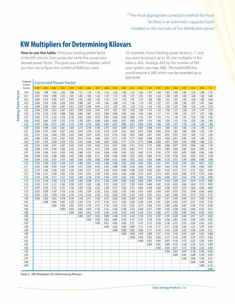
KW Multipliers for Determining KilovarsHow to use this table: Find your existing power factor
in the left column, then across the same line, locate your
desired power factor. This gives you a KW multiplier, which
you then use to figure the number of KVAR you need.
For example, if your existing power factor is .71 and
you want to bring it up to .95, the multiplier in the
table is .663. Multiply .663 by the number of KW
your system uses (say, 590). The total KVAR this
would require is 390, which can be rounded up to
400 KVAR.
Table 2. KW Multipliers for Determining Kilovars
Corrected Power Factor
“The most appropriate correction method for most
facilities is an automatic capacitor bank
installed on the bus bars of the distribution panel.”
12
Power Factor Correction
www.stacoenergy.comPFC-HFC Primer
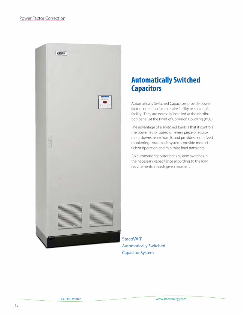
Automatically Switched Capacitors
Automatically Switched Capacitors provide power
factor correction for an entire facility or sector of a
facility. They are normally installed at the distribu-
tion panel, at the Point of Common Coupling (PCC).
The advantage of a switched bank is that it controls
the power factor based on every piece of equip-
ment downstream from it, and provides centralized
monitoring. Automatic systems provide more ef-
ficient operation and minimize load transients.
An automatic capacitor bank system switches in
the necessary capacitance according to the load
requirements at each given moment.
StacoVAR®
Automatically Switched
Capacitor System
SA
C

13
Staco Energy Products Co.
A Checklist for Switched Capacitor Banks
The following checklist can be used to help you determine your exact requirements, and assist in choosing the best system for your needs.
Nominal System Voltage:
208 VAC: ____________ 240 VAC: ____________ 415 VAC: ______________
480 VAC: ____________ 600 VAC: ____________ Other: _______________
Wiring Connection:
DELTA: ____________________ Ungrounded WYE: ____________________
Grounded WYE: _____________
Frequency: 50 Hz: ______________ 60 Hz: _______________ Other: ____________
KVAR Requirements:
Total Rating: ___________________ Fixed KVAR: ______________________
Number of Switched Steps: _________________________________________
Size of Step: 1:_______ 2:________ 3:________ 4:________ 5:________ 6:________
Capacitor Type:
Heavy Duty STD: _________________________________________________
Harmonic Filter Application: _________________________________________
Special Type: _____________________________________________________
Capacitor Switching:
Three Phase Electro-Mechanical Contactor: __________________________ Type of Disconnect and Incoming
Lugs Only: ____________________________________________________
Type of Circuit Breaker or Switch: __________________________________
Existing Customer Disconnect: _____________________________________
Cable Entry: Bottom: STD Top: ______ Other: _______ (Dead Front, Roof Bushings)
Non-Standard Type of Fusing:
VAC: ________
Fusing: Main (Group) Amps: ________ Type: _______
Fusing: Capacitor: Step: STD
Type of Enclosure:
Indoor STD Outdoor: _________________________________________
Special Environment: ____________________________________________
Paint Color: Grey STD Other: __________________________________
Heater/Thermostat: _____________ Fans: __________________________
Conditioned Air: ________________________________________________
Lighting (Internal/External): _______________________________________
Receptacles: ___________________________________________________
Power Factor Controller: StacoVAR® STD Real Time: ________________
Type of Controls:
Neutral Unbalanced Protection: ____________________________________
Blown Fuse Indication: ___________________________________________
Customer Specific Devices: _______________________________________
PLC/Networking/SCADA: _________________________________________
Other Devices or Integration:
Surge/Lightning Arrestor or TVSS (Type): ____________________________
Lights: ________________________________________________________
CT: _______________________________________ (split core or other type)
Ratio: ________________________________________________________
Other: ________________________________________________________
Harmonic Filtering Description: ____________________________________ _______________________________________________________
For additional information on harmonic filtering, including applications, reactor type, and active filters, please refer to the Harmonic Mitigation section of this document.
Other ConsiderationsSome general power factor determinations can be found
simply based on a facility review and electric billing by an
analyst. Some electric utilities may offer analysis support.
Contact Staco for a complete review of your power bill
and application recommendations.
“Some utility companies offer analysis or
referrals for businesses wanting to improve
their electrical efficiency.”
14
Power Factor Correction
www.stacoenergy.comPFC-HFC Primer
Fixed Capacitors
Fixed capacitor assemblies, sometimes called motor load
capacitors, are ideal for improving power factor where
induction motors are located. They are also used anywhere
there are small KVAR requirements.
Motor Capacitor Selection
You can achieve maximum benefits from capacitors when
they are located at the load. Because the capacitor is
usually switched on and off with the load, over-correction
is also avoided.
However, capacitors must be carefully sized when switched
with the motor as a unit, because dangerous over voltages
and transient torques can occur if the capacitor’s KVAR
exceeds the motor’s magnetizing current. The motor
reference tables on the following pages are provided to
help you select the correct capacitor size for your load.
CAUTION: All conditions of the motor reference tables must be met to ensure that over-correction does not occur. If any condition is in doubt, then the motor manufacturer should be consulted.
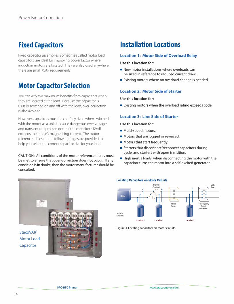
Figure 4. Locating capacitors on motor circuits.
StacoVAR®
Motor Load
Capacitor
Installation Locations
Location 1: Motor Side of Overload Relay
Use this location for:
New motor installations where overloads can be sized in reference to reduced current draw.
Existing motors where no overload change is needed.
Location 2: Motor Side of Starter
Use this location for:
Existing motors when the overload rating exceeds code.
Location 3: Line Side of Starter
Use this location for:
Multi-speed motors. Motors that are jogged or reversed. Motors that start frequently. Starters that disconnect/reconnect capacitors during
cycle, and starters with open transition. High inertia loads, when disconnecting the motor with the
capacitor turns the motor into a self-excited generator.
15
Staco Energy Products Co.
Motor Stator
Motor Stator
Motor Stator
Motor Stator
5
4
3
2
1
3
2
1
6
5
4
9
8
7
C
B
A
C
B
A
6
7 Line
Line
A
Line
3
B 2
C 1
6
5
4
A B
C Li ne
6 5 4
2
1
3
1
2
Line
4
B5
A
7
8
63
C
MotorStator
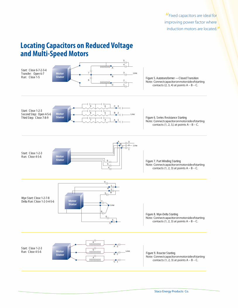
Figure 5. Autotransformer — Closed TransitionNote: Connect capacitor on motor side of starting
contacts (2, 3, 4) at points A – B – C.
Start: Close 6-7-2-3-4 Transfer: Open 6-7 Run: Close 1-5
Locating Capacitors on Reduced Voltage and Multi-Speed Motors
Figure 6. Series Resistance StartingNote: Connect capacitor on motor side of starting
contacts (1, 2, 3,) at points A – B – C.
Start: Close 1-2-3 Second Step: Open 4-5-6 Third Step: Close 7-8-9
Figure 7. Part Winding StartingNote: Connect capacitor on motor side of starting
contacts (1, 2, 3) at points A – B – C.
Start: Close 1-2-3 Run: Close 4-5-6
Figure 8. Wye-Delta StartingNote: Connect capacitor on motor side of starting
contacts (1, 2, 3) at points A – B – C.
Wye Start: Close 1-2-7-8 Delta Run: Close 1-2-3-4-5-6
Figure 9. Reactor StartingNote: Connect capacitor on motor side of starting
contacts (1, 2, 3) at points A – B – C.
Start: Close 1-2-3 Run: Close 4-5-6
“Fixed capacitors are ideal for
improving power factor where
induction motors are located.”
16
Power Factor Correction
www.stacoenergy.comPFC-HFC Primer
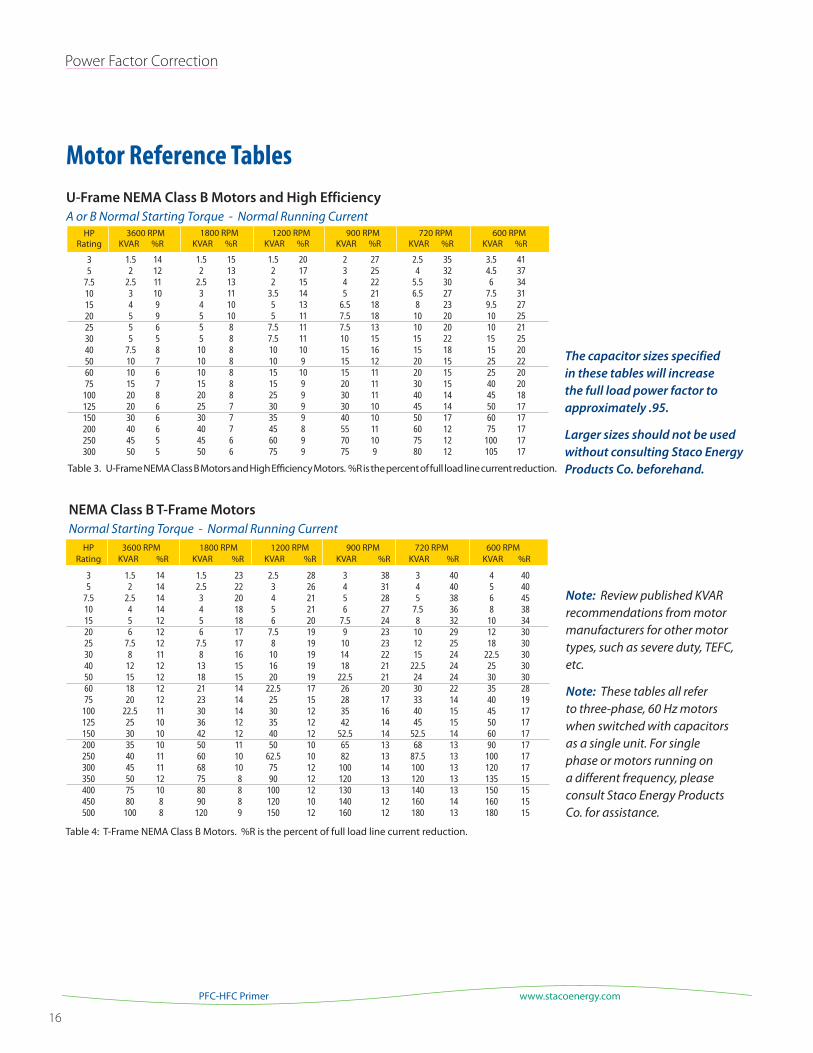
U-Frame NEMA Class B Motors and High Efficiency
A or B Normal Starting Torque - Normal Running Current3600 RPM
KVAR %R
1.5 14 2 12 2.5 11 3 10 4 9 5 9 5 6 5 5 7.5 8 10 7 10 6 15 7 20 8 20 6 30 6 40 6 45 5 50 5
HP Rating
35
7.5101520253040506075
100125150200250300
1800 RPMKVAR %R
1.5 15 2 13 2.5 13 3 11 4 10 5 10 5 8 5 8 10 8 10 8 10 8 15 8 20 8 25 7 30 7 40 7 45 6 50 6
1200 RPMKVAR %R
1.5 20 2 17 2 15 3.5 14 5 13 5 11 7.5 11 7.5 11 10 10 10 9 15 10 15 9 25 9 30 9 35 9 45 8 60 9 75 9
900 RPMKVAR %R
2 27 3 25 4 22 5 21 6.5 18 7.5 18 7.5 13 10 15 15 16 15 12 15 11 20 11 30 11 30 10 40 10 55 11 70 10 75 9
720 RPMKVAR %R
2.5 35 4 32 5.5 30 6.5 27 8 23 10 20 10 20 15 22 15 18 20 15 20 15 30 15 40 14 45 14 50 17 60 12 75 12 80 12
600 RPMKVAR %R
3.5 41 4.5 37 6 34 7.5 31 9.5 27 10 25 10 21 15 25 15 20 25 22 25 20 40 20 45 18 50 17 60 17 75 17 100 17 105 17
HP Rating
35
7.5101520253040506075
100125150200250300350400450500
3600 RPMKVAR %R
1.5 14 2 14 2.5 14 4 14 5 12 6 12 7.5 12 8 11 12 12 15 12 18 12 20 12 22.5 11 25 10 30 10 35 10 40 11 45 11 50 12 75 10 80 8 100 8
1800 RPMKVAR %R
1.5 23 2.5 22 3 20 4 18 5 18 6 17 7.5 17 8 16 13 15 18 15 21 14 23 14 30 14 36 12 42 12 50 11 60 10 68 10 75 8 80 8 90 8 120 9
1200 RPMKVAR %R
2.5 28 3 26 4 21 5 21 6 20 7.5 19 8 19 10 19 16 19 20 19 22.5 17 25 15 30 12 35 12 40 12 50 10 62.5 10 75 12 90 12 100 12 120 10 150 12
900 RPMKVAR %R
3 38 4 31 5 28 6 27 7.5 24 9 23 10 23 14 22 18 21 22.5 21 26 20 28 17 35 16 42 14 52.5 14 65 13 82 13 100 14 120 13 130 13 140 12 160 12
720 RPMKVAR %R
3 40 4 40 5 38 7.5 36 8 32 10 29 12 25 15 24 22.5 24 24 24 30 22 33 14 40 15 45 15 52.5 14 68 13 87.5 13 100 13 120 13 140 13 160 14 180 13
600 RPMKVAR %R
4 40 5 40 6 45 8 38 10 34 12 30 18 30 22.5 30 25 30 30 30 35 28 40 19 45 17 50 17 60 17 90 17 100 17 120 17 135 15 150 15 160 15 180 15
Table 4: T-Frame NEMA Class B Motors. %R is the percent of full load line current reduction.
NEMA Class B T-Frame Motors
Normal Starting Torque - Normal Running Current
Motor Reference Tables
Table 3. U-Frame NEMA Class B Motors and High Efficiency Motors. %R is the percent of full load line current reduction.
Note: Review published KVAR recommendations from motor manufacturers for other motor types, such as severe duty, TEFC, etc.
Note: These tables all refer to three-phase, 60 Hz motors when switched with capacitors as a single unit. For single phase or motors running on a different frequency, please consult Staco Energy Products Co. for assistance.
The capacitor sizes specified in these tables will increase the full load power factor to approximately .95.
Larger sizes should not be used without consulting Staco Energy Products Co. beforehand.
17
Staco Energy Products Co.
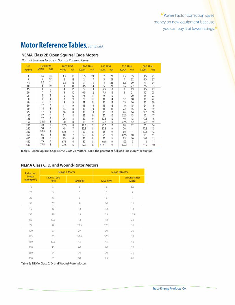
NEMA Class 2B Open Squirrel Cage Motors
Normal Starting Torque - Normal Running Current
HP Rating
35
7.5101520253040506075
100125150200250300350400450500
3600 RPMKVAR %R
1.5 14 2 12 2.5 11 3 10 4 9 5 9 6 9 7 8 9 8 12 8 14 8 17 8 22 8 27 8 32.5 8 40 8 50 8 57.5 8 65 8 70 8 75 8 77.5 8
1800 RPMKVAR %R
1.5 15 2 13 2.5 12 3 11 4 10 5 10 6 10 7 9 9 9 11 9 14 8 16 8 21 8 26 8 30 8 37.5 8 45 7 52.5 7 60 7 65 6 67.5 6 72.5 6
1200 RPMKVAR %R
1.5 20 2 17 3 15 3.5 14 5 13 6.5 12 7.5 11 9 11 11 9 13 10 15 10 18 10 25 9 30 9 35 9 42.5 9 52.5 8 60 8 67.5 8 75 8 80 8 82.5 8
900 RPMKVAR %R
2 27 3 25 4 22 5 21 6.5 18 7.5 16 9 15 10 14 12 13 15 12 18 11 21 10 27 10 32.5 10 37.5 10 47.5 10 57.5 9 65 9 75 9 85 9 92.5 9 97.5 9
720 RPMKVAR %R
2.5 35 4 32 5.5 30 6.5 27 8 23 9 21 11 20 12 18 15 16 19 15 22 15 26 14 32.5 13 40 13 47.5 12 60 12 70 11 80 11 87.5 10 95 10 100 9 107.5 9
600 RPMKVAR %R
3.5 41 4.5 37 6 34 7.5 31 9.5 27 12 25 14 23 16 22 20 20 24 19 27 19 32.5 18 40 17 47.5 16 52.5 15 65 14 77.5 13 87.5 12 95 11 105 11 110 11 115 10
Table 5: Open Squirrel Cage NEMA Class 2B Motors. %R is the percent of full load line current reduction.
Motor Reference Tables, continued
Table 6: NEMA Class C, D, and Wound-Rotor Motors.
Design C Motor Design D Motor
NEMA Class C, D, and Wound-Rotor Motors
Induction Motor 1800 & 1200 Wound-Rotor Rating (HP) RPM 900 RPM 1200 RPM Motor
15 5 5 5 5.5
20 5 6 6 7
25 6 6 6 7
30 7.5 9 10 11
40 10 12 12 13
50 12 15 15 17.5
60 17.5 18 18 20
75 19 22.5 22.5 25
100 27 27 30 25
125 35 37.5 37.5 33
150 37.5 45 45 40
200 45 60 60 50
250 54 70 70 75
300 65 90 75 85
“Power Factor Correction saves
money on new equipment because
you can buy it at lower ratings.”
18
Power Factor Correction
www.stacoenergy.comPFC-HFC Primer
KVAR Current Wire Fuse Switch Current Wire Fuse Switch Current Wire Fuse Switch (Amps) Size (Amps) (Amps) (Amps) Size (Amps) (Amps) (Amps) Size (Amps) (Amps)
2 4.8 14 10 30 2.4 14 6 30 1.9 14 6 30 2.5 6.0 14 10 30 3.0 14 6 30 2.4 14 6 30 3 7.2 14 15 30 3.6 14 6 30 2.9 14 6 30 4 9.6 14 20 30 4.8 14 10 30 3.8 14 10 30 5 12 14 20 30 6.0 14 10 30 4.8 14 10 30
6 14 14 25 30 7.2 14 15 30 5.8 14 10 30 7.5 18 12 30 30 9.0 14 15 30 7.2 14 15 30 8 19 10 35 60 9.6 14 20 30 7.7 14 15 30 10 24 10 40 60 12 14 20 30 9.6 14 20 30 12.5 30 8 50 60 15 14 25 30 12 14 20 30 15 36 8 60 60 18 12 30 30 14 14 25 30 17.5 42 6 80 100 21 10 40 60 17 12 30 30 20 48 6 80 100 24 10 40 60 19 10 35 60
22.5 54 4 100 100 27 10 50 60 22 10 40 60 25 60 4 100 100 30 8 50 60 24 10 40 60 30 72 3 125 200 36 8 60 60 29 8 50 60 35 84 2 150 200 42 6 80 100 34 8 60 60 40 96 1 175 200 48 6 80 100 38 6 80 100 45 108 1/0 200 200 54 4 100 100 43 6 90 100 50 120 2/0 200 200 60 4 100 100 48 6 100 100
60 144 3/0 250 400 72 2 125 200 58 4 100 100 75 180 250M 300 400 90 1/0 150 200 72 3 125 200 80 192 300M 350 400 96 1/0 175 200 77 3 150 200 90 216 350M 400 400 108 1/0 200 200 86 1 150 200 100 241 400M 400 400 120 2/0 200 200 96 1 175 200
120 289 (2)3/0 500 600 144 3/0 200 200 115 2/0 200 200 125 300 (2)3/0 500 600 150 3/0 250 400 120 2/0 200 200 150 361 (2)250M 600 600 180 250M 300 400 144 3/0 250 400 180 432 (2)350M 750 800 216 350M 400 400 173 250M 300 400 200 481 (2)400M 800 800 241 400M 400 400 192 300M 350 400
240 — — — — 289 (2)3/0 500 600 231 400M 400 400 250 — — — — 300 (2)3/0 500 600 241 400M 400 400 300 — — — — 361 (2)250M 600 600 289 (2)3/0 500 600 360 — — — — 432 (2)350M 750 800 246 (2)250M 600 600 400 — — — — 480 (2)500M 800 800 284 (2)300M 650 800
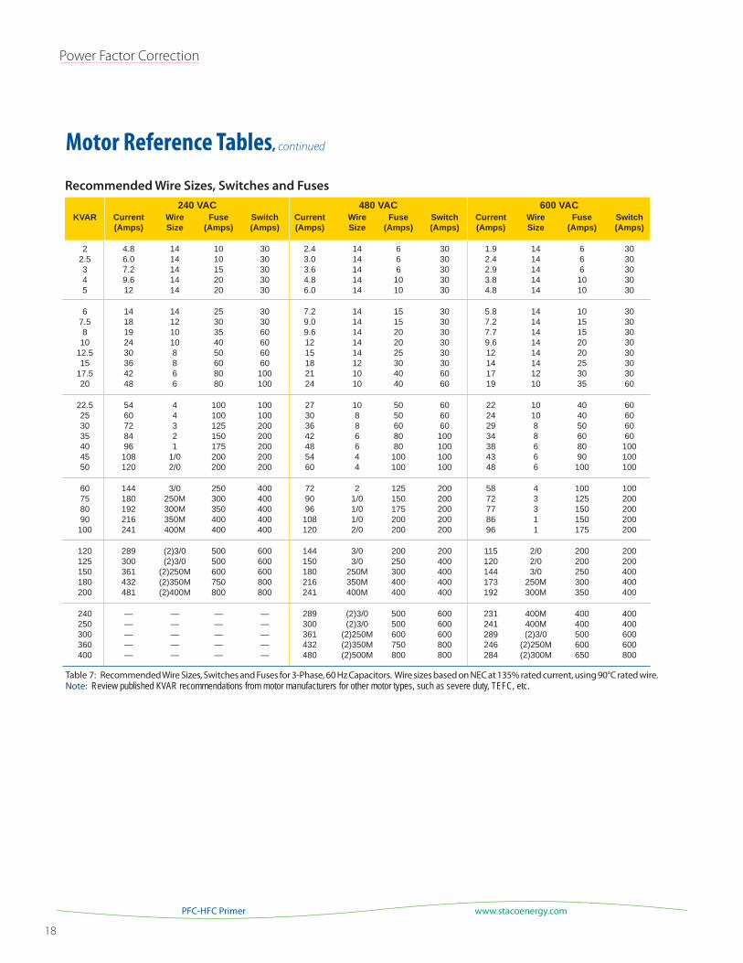
Motor Reference Tables, continued
240 VAC 480 VAC 600 VAC
Table 7: Recommended Wire Sizes, Switches and Fuses for 3-Phase, 60 Hz Capacitors. Wire sizes based on NEC at 135% rated current, using 90°C rated wire. Note: Review published KVAR recommendations from motor manufacturers for other motor types, such as severe duty, TEFC, etc.
Recommended Wire Sizes, Switches and Fuses
19
Staco Energy Products Co.
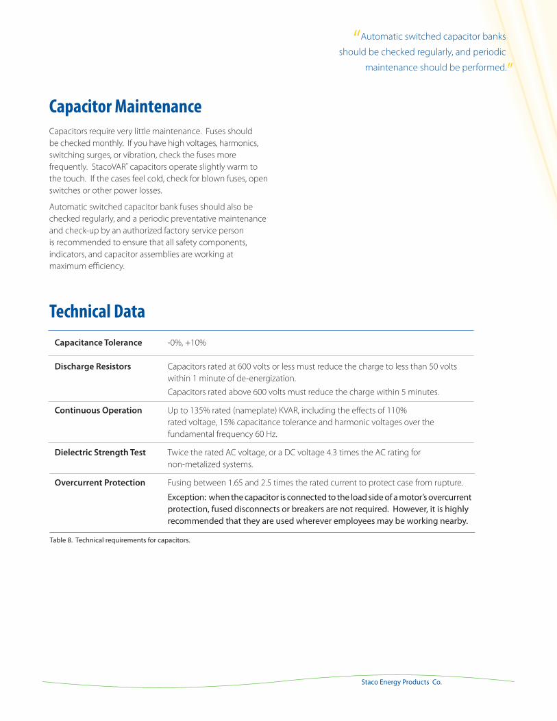
Capacitance Tolerance -0%, +10%
Discharge Resistors Capacitors rated at 600 volts or less must reduce the charge to less than 50 volts
within 1 minute of de-energization.
Capacitors rated above 600 volts must reduce the charge within 5 minutes.
Continuous Operation Up to 135% rated (nameplate) KVAR, including the effects of 110%
rated voltage, 15% capacitance tolerance and harmonic voltages over the
fundamental frequency 60 Hz.
Dielectric Strength Test Twice the rated AC voltage, or a DC voltage 4.3 times the AC rating for
non-metalized systems.
Overcurrent Protection Fusing between 1.65 and 2.5 times the rated current to protect case from rupture. Exception: when the capacitor is connected to the load side of a motor’s overcurrent protection, fused disconnects or breakers are not required. However, it is highly recommended that they are used wherever employees may be working nearby.
Capacitor Maintenance
Capacitors require very little maintenance. Fuses should
be checked monthly. If you have high voltages, harmonics,
switching surges, or vibration, check the fuses more
frequently. StacoVAR® capacitors operate slightly warm to
the touch. If the cases feel cold, check for blown fuses, open
switches or other power losses.
Automatic switched capacitor bank fuses should also be
checked regularly, and a periodic preventative maintenance
and check-up by an authorized factory service person
is recommended to ensure that all safety components,
indicators, and capacitor assemblies are working at
maximum efficiency.
Table 8. Technical requirements for capacitors.
Technical Data
“Automatic switched capacitor banks
should be checked regularly, and periodic
maintenance should be performed.”
20
Harmonic Mitigation
www.stacoenergy.comPFC-HFC Primer
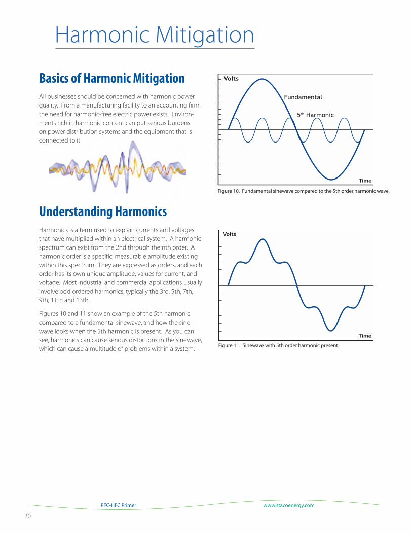
Figure 10. Fundamental sinewave compared to the 5th order harmonic wave.
Figure 11. Sinewave with 5th order harmonic present.
Harmonic Mitigation
Basics of Harmonic Mitigation
All businesses should be concerned with harmonic power
quality. From a manufacturing facility to an accounting firm,
the need for harmonic-free electric power exists. Environ-
ments rich in harmonic content can put serious burdens
on power distribution systems and the equipment that is
connected to it.
Understanding Harmonics
Harmonics is a term used to explain currents and voltages
that have multiplied within an electrical system. A harmonic
spectrum can exist from the 2nd through the nth order. A
harmonic order is a specific, measurable amplitude existing
within this spectrum. They are expressed as orders, and each
order has its own unique amplitude, values for current, and
voltage. Most industrial and commercial applications usually
involve odd ordered harmonics, typically the 3rd, 5th, 7th,
9th, 11th and 13th.
Figures 10 and 11 show an example of the 5th harmonic
compared to a fundamental sinewave, and how the sine-
wave looks when the 5th harmonic is present. As you can
see, harmonics can cause serious distortions in the sinewave,
which can cause a multitude of problems within a system.
21
Staco Energy Products Co.
Table 10. IEEE 519 voltage distortion limits
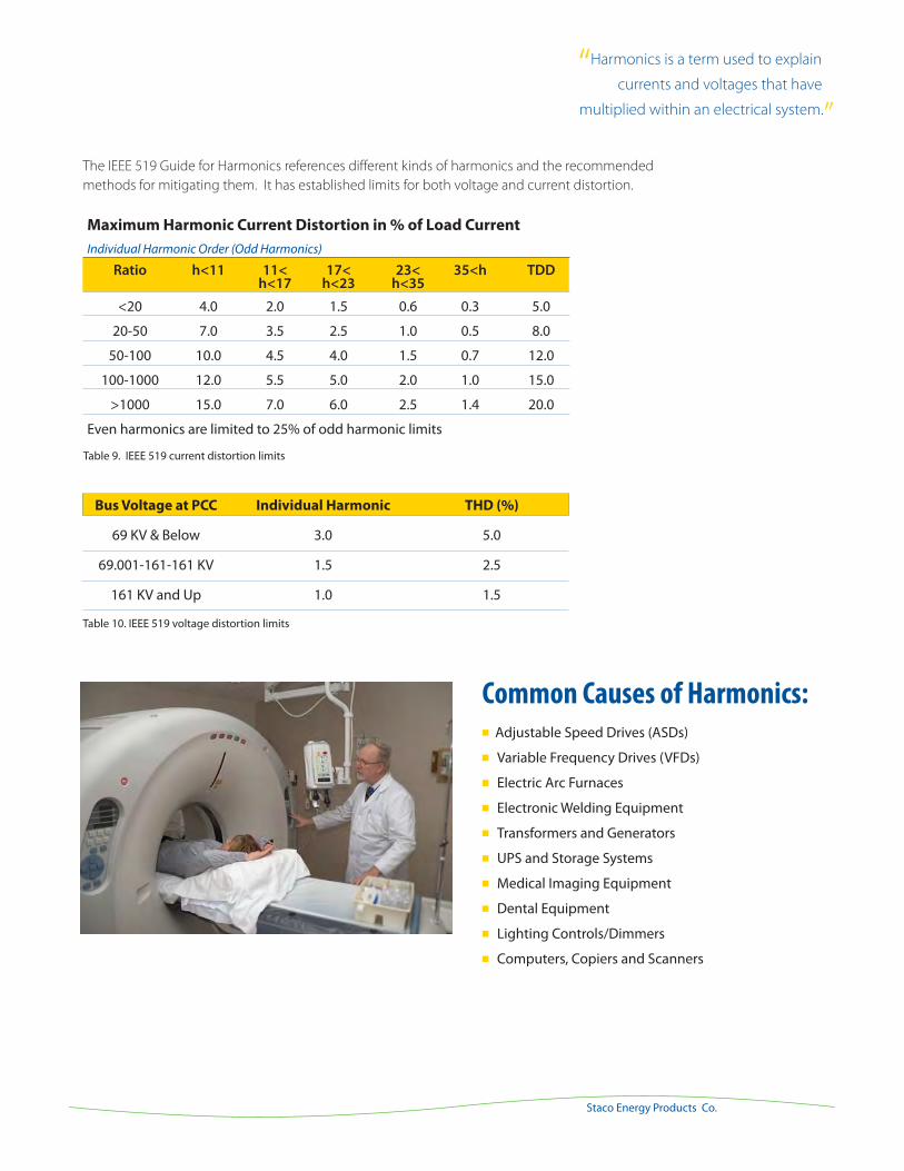
Common Causes of Harmonics: Adjustable Speed Drives (ASDs)
Variable Frequency Drives (VFDs)
Electric Arc Furnaces
Electronic Welding Equipment
Transformers and Generators
UPS and Storage Systems
Medical Imaging Equipment
Dental Equipment
Lighting Controls/Dimmers
Computers, Copiers and Scanners
The IEEE 519 Guide for Harmonics references different kinds of harmonics and the recommended
methods for mitigating them. It has established limits for both voltage and current distortion.
Bus Voltage at PCC Individual Harmonic THD (%)
69 KV & Below 3.0 5.0
69.001-161-161 KV 1.5 2.5
161 KV and Up 1.0 1.5
Table 9. IEEE 519 current distortion limits
Maximum Harmonic Current Distortion in % of Load Current
Individual Harmonic Order (Odd Harmonics)
Ratio h<11 11< 17< 23< 35<h TDD h<17 h<23 h<35
<20 4.0 2.0 1.5 0.6 0.3 5.0
20-50 7.0 3.5 2.5 1.0 0.5 8.0
50-100 10.0 4.5 4.0 1.5 0.7 12.0
100-1000 12.0 5.5 5.0 2.0 1.0 15.0
>1000 15.0 7.0 6.0 2.5 1.4 20.0
Even harmonics are limited to 25% of odd harmonic limits
“Harmonics is a term used to explain
currents and voltages that have
multiplied within an electrical system.”
22
Harmonic Mitigation
www.stacoenergy.comPFC-HFC Primer
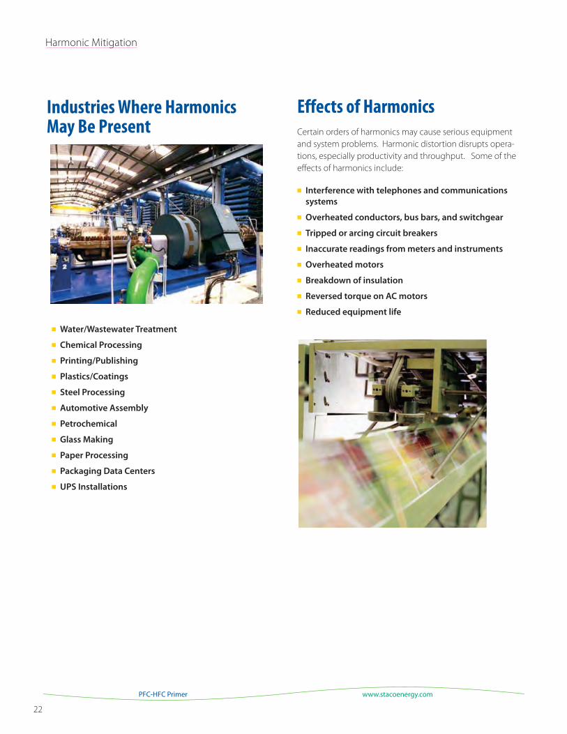
Industries Where Harmonics May Be Present
Water/Wastewater Treatment
Chemical Processing
Printing/Publishing
Plastics/Coatings
Steel Processing
Automotive Assembly
Petrochemical
Glass Making
Paper Processing
Packaging Data Centers
UPS Installations
Effects of Harmonics
Certain orders of harmonics may cause serious equipment
and system problems. Harmonic distortion disrupts opera-
tions, especially productivity and throughput. Some of the
effects of harmonics include:
Interference with telephones and communications
systems
Overheated conductors, bus bars, and switchgear
Tripped or arcing circuit breakers
Inaccurate readings from meters and instruments
Overheated motors
Breakdown of insulation
Reversed torque on AC motors
Reduced equipment life
23
Staco Energy Products Co.
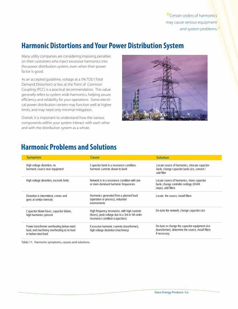
Many utility companies are considering imposing penalties
on their customers who inject excessive harmonics into
the power distribution system, even when their power
factor is good.
As an accepted guideline, voltage at a 5% TDD (Total
Demand Distortion) or less at the Point of Common
Coupling (PCC) is a practical recommendation. This value
generally refers to system wide harmonics, helping assure
efficiency and reliability for your operations. Some electri-
cal power distribution centers may function well at higher
limits, and may need only minimal mitigation.
Overall, it is important to understand how the various
components within your system interact with each other
and with the distribution system as a whole.
Symptom Cause Solution
High voltage distortion, no harmonic source near equipment
High voltage distortion, exceeds limits
Distortion is intermittent, comes and goes at similar intervals
Capacitor blown fuses, capacitor failure, high harmonics present
Power transformer overheating below rated load, and machinery overheating at no load or below rated load
Capacitor bank in a resonance condition, harmonic currents drawn to bank
Network is in a resonance condition with one or more dominant harmonic frequencies
Harmonics generated from a planned load (operation or process), industrial environments
High frequency resonance, with high currents (fuses), peak voltage due to a 3rd or 5th order resonance condition (capacitors)
Excessive harmonic currents (transformer), high voltage distortion (machinery)
Locate source of harmonics, relocate capacitor bank, change capacitor bank size, convert / add filter
Locate source of harmonics, move capacitor bank, change controller settings (KVAR steps), add filters
Locate the source, install filters
De-tune the network, change capacitor size
De-tune or change the capacitor equipment size (transformer), determine the source, install filters if necessary
Harmonic Problems and Solutions
Table 11. Harmonic symptoms, causes and solutions.
Harmonic Distortions and Your Power Distribution System
“Certain orders of harmonics
may cause serious equipment
and system problems.”

24
Harmonic Mitigation
www.stacoenergy.comPFC-HFC Primer
If you suspect that you have a harmonics problem, first look
at the effects of harmonics listed earlier in this section. If
one or more of these symptoms occurs regularly, then the
following steps will help you narrow down the problem.
1. If you have power factor correction capacitors, measure
the current going into the capacitors. It should be
measured using a “true rms” current meter. If the current
value is higher than the capacitor’s rated current by 5%
or more, the presence of harmonics is likely.
2. Audit any harmonic producing loads and your system
configuration. Start by listing the kVA or horsepower
data on all major non-linear devices and capacitors.
Also list the rating information on the service entrance
transformers. A short requirements review form is given
later in this document to help with this process.
3. If your electrical distribution system is complex, or
the labor to perform an internal audit is too intensive,
consider having an on-site audit conducted by an
independent consultant. Your local utility may be able
to provide or recommend an experienced consultant.
If not, contact Staco Energy Products Co. for a referral
to an independent consultant in your area who can
perform a complete power quality audit for you.
Normally, a power quality audit involves
inspection of the electrical system
layout, connected loads, and harmonic
measurements at strategic locations.
Measurements are taken over time to
get a realistic assessment of the system’s
load. All the data is then analyzed to
get an accurate picture of your situation
and suggest options for correction when
needed.
Diagnosing Harmonic Related Problems
25
Staco Energy Products Co.
Harmonic 3 5 7 9 11 13 15 17
0.0%
17 .5%
11 .1%
0.0%
4.5%
2.9%1.0% 0. 8%
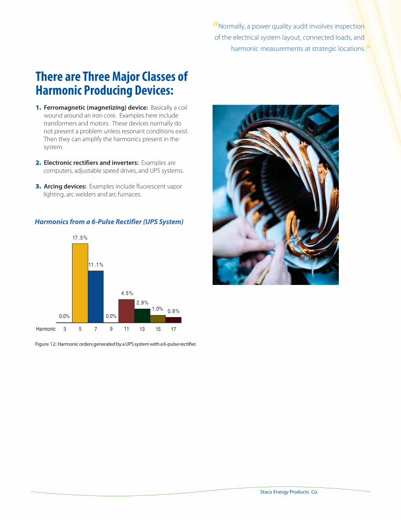
There are Three Major Classes of Harmonic Producing Devices:1. Ferromagnetic (magnetizing) device: Basically a coil
wound around an iron core. Examples here include
transformers and motors. These devices normally do
not present a problem unless resonant conditions exist.
Then they can amplify the harmonics present in the
system.
2. Electronic rectifiers and inverters: Examples are
computers, adjustable speed drives, and UPS systems.
3. Arcing devices: Examples include fluorescent vapor
lighting, arc welders and arc furnaces.
Figure 12: Harmonic orders generated by a UPS system with a 6-pulse rectifier.
Harmonics from a 6-Pulse Rectifier (UPS System)
“Normally, a power quality audit involves inspection...
of the electrical system layout, connected loads, and...
harmonic measurements at strategic locations.”
26
Harmonic Mitigation
www.stacoenergy.comPFC-HFC Primer
Requirements Review Checklist
Initial review data should include: Previous six to twelve months of electric utility billing data, contract, and tariffs agreements.
This should also include rate structure, load usage, KW/KVA, peak demand and power factor penalty.
Single line diagram of the building or facility, with all updates or revisions
Plans for new capital equipment installations, general equipment upgrades, facility expansion, or improvements
Most recent data from instrument measurements, site survey, general equipment and system notes, past electrical
system studies
Complete the following information to better understand the application requirements and assist with initial system
parameters.
Primary voltage____________________________________________ (line-to-line)
Secondary voltage _________________________________________ (line-to-line)
System short circuit capability _______________________________________________________________
Transformer rating (KVA) ___________________________________________________________________
Transformer impedance (%) _________________________________________________________________
Wire/Cable/Bus Systems ___________________________________________________________________
Copper or aluminum ______________________________________________________________________
Ratings and size __________________________________________________________________________
Length of runs, ways, systems and locations (provide single line with specific comments) ___________________
________________________________________________________________________________________
Installed Equipment
List each device or piece of equipment. Nameplate data and/or instruction manuals should contain pertinent
information. Office equipment, computer and communication systems should also be considered.
For example:
Drive Type(s): Manufacturer, H.P./KW, Amperes, KVA , PF Pulse (AC/DC)
_____________________________________________________________________________________________
Capacitor Type: Manufacturer, KVAR, voltage, fixed/switched, phases, fusing, present minimum power factor, maximum power factor, utility limit, and desired power factor, if applicable
_____________________________________________________________________________________________
Communications: Interface, tele/data, satellite
_____________________________________________________________________________________________

27
Staco Energy Products Co.
Other Considerations
What equipment, processes and operations are the most vulnerable? ________________________________________
________________________________________________________________________________________________
Are there critical loads and a need for “high nines” type power? _____________________________________________
_______________________________________________________________________________________________
Have there been both long and short term outages? _____________________________________________________
_______________________________________________________________________________________________
Does a routine maintenance plan exist? _______________________________________________________________
_______________________________________________________________________________________________
Have UPS, voltage regulation, generation, power distribution, motors/drives, and other power quality equipment been
evaluated to meet existing and future expansion needs? __________________________________________________
________________________________________________________________________________________________
What are the costs for downtime, maintenance, scrap, lost production, return to uptime (waiting for parts, new equipment)?
_______________________________________________________________________________________________
Other Equipment to Consider:
UPS Battery Chargers Rectifiers Motors Other Storage Systems
Load Banks Resistor Banks Furnaces HVAC Generators
Lighting Systems Compressors Prime Power/DG Emergency/Standby Power
After collecting this information, an engineering service firm or power quality consultant may be required to perform
an analysis and computer modeling and equipment sizing study. There may be several solutions, which should be
reviewed based upon the need to correct an isolated problem, resolve system wide concerns, or develop and
implement a long-term power quality strategy.
“A requirements review should include current usage...
information, plans for capital equipment upgrades...
or installations and facility expansion or improvements.”

28
Harmonic Mitigation
www.stacoenergy.comPFC-HFC Primer
Solutions
Many standard harmonic reduction solutions are available,
including reactors, isolation transformers, filters and active
devices.
Harmonics solutions can range from simple corrections
like tightening connections in a switchboard to help the
overheating of conductors, using a 200% rated neutral in
a panel board, all the way to incorporating sophisticated
active harmonic filters. All have strengths and weaknesses,
and should be considered carefully in the context of your
particular harmonics problems.
Harmonic mitigation is especially important when power
factor correction capacitors are already installed in your
facility, or if you plan on adding them in the future. Even
though capacitors do not create harmonics, they resonate
and amplify existing harmonics. Adding passive harmonic
filters to your capacitors will protect your capacitors from
being damaged by existing harmonics.
There are two approaches to harmonic mitigation: treat
the symptoms, or treat the source.
Treat the Symptoms
In some facilities, it’s best (and easiest) to treat the
symptoms of harmonics. If your only problem is neutral
conductor overheating, you can increase the conductor’s
size. If your transformers are overheating, you can install
special K-rated transformers designed to better tolerate
harmonics. You can relocate harmonic producing loads
around your facility to balance the harmonics and produce
a better sine wave. You can also use a “zigzag” transformer
for a similar re-distribution.
Treating the symptoms of harmonics may be a simple
exercise in some facilities. Others have more problems from
harmonics than can be addressed symptom by symptom.
Treat the Source
When treating the source of harmonics, a power quality
study or measurements from monitoring equipment,
normally will show a need for a more complex solution.
To reduce the level of harmonics produced by a facility’s
equipment, impedance may be added by installing line
reactors at the source, or passive filters can be installed to
eliminate specific harmonic frequencies, or an active filter
can be installed to address a broad range of harmonic
orders when they are present.
An ideal time to consider harmonic mitigation strategies is
during the design of new facilities or at the time of equip-
ment purchases. Harmonics producing equipment can
be identified and mitigation devices installed with the
equipment. Transformers and neutral conductors can be
specified properly. However, once operational, additional
equipment may be needed.
Six-pulse rectified power supplies like those found in many
variable frequency drives, may be replaced with twelve or
higher pulse rectifiers. However, this solution is not likely
to be cost effective unless done when the equipment is
purchased.
Some variable speed drive manufacturers now offer har-
monics correcting components as standard features of their
drives, and others offer them as factory installed options.
Be sure to ask your drive representative about harmonics
correction when specifying a new variable speed drive.
29
Staco Energy Products Co.
Selecting Harmonic Mitigation Equipment
Some widely used mitigation options include:
Over-sizing or Derating
Series Reactors
Passive Filters
Tuned Filters
Active Filters
With most filtering options, the installation location is
critical to the filter’s effectiveness. Eliminating harmon-
ics at their source is the most effective option from a
systems point of view. Many manufacturers today are
adding some filtering within the equipment itself. But
many can’t, due to the nature of the machinery, or a
prohibitive cost.
Over-sizing the Installation
This method doesn’t really mitigate harmonics, but
simply over-sizes the elements in the system that are
likely to resonate harmonics, such as transformers,
cables, circuit breakers and the distribution panel.
The most common way of dealing with harmonics
in this way is to over-size the neutral conductor or to
derate the distribution equipment that is subjected
to harmonics.
Over-sizing or derating results in significantly higher
costs in the distribution system. It also means that the
system cannot be used to its full potential, and puts
an increased demand on the system.
Series Reactors
Series reactors are often used for mitigating the
harmonics caused by variable frequency and adjustable
speed drives. Reactors are connected in series,
upstream of the load. One must be installed for each
drive or load. If you have multiple drives, or other
non-linear loads that need mitigation, this can be an
expensive solution. Although series reactors can cut
harmonic distortion in half, it can still be higher than
the IEEE 519 standard.
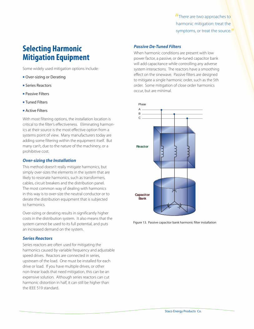
Passive De-Tuned Filters
When harmonic conditions are present with low
power factor, a passive, or de-tuned capacitor bank
will add capacitance while controlling any adverse
system interactions. The reactors have a smoothing
effect on the sinewave. Passive filters are designed
to mitigate a single harmonic order, such as the 5th
order. Some mitigation of close order harmonics
occur, but are minimal.
PhaseABC
CapacitorBank
Reactor
Figure 13. Passive capacitor bank harmonic filter installation
“There are two approaches to...
harmonic mitigation: treat the...
symptoms, or treat the source.”
30
Harmonic Mitigation
www.stacoenergy.comPFC-HFC Primer
Passive Tuned Filters
Also called shunt, parallel or harmonic trap filters, these fil-
ters use inductance and capacitance to provide mitigation
for a specific harmonic order. Although a shunt filter is also
a passive harmonic filter, it does not provide any power
factor correction.
The filter is connected in parallel with the power system to
divert the tuned frequency currents away from the power
source. Shunt filters perform best at full loads. At lighter
loads, distortion can increase and performance will be less
efficient.
With any passive filter installation, an application engineer-
ing or power quality study should be done to determine
the sizing and installation locations of the filters for an
individual facility.
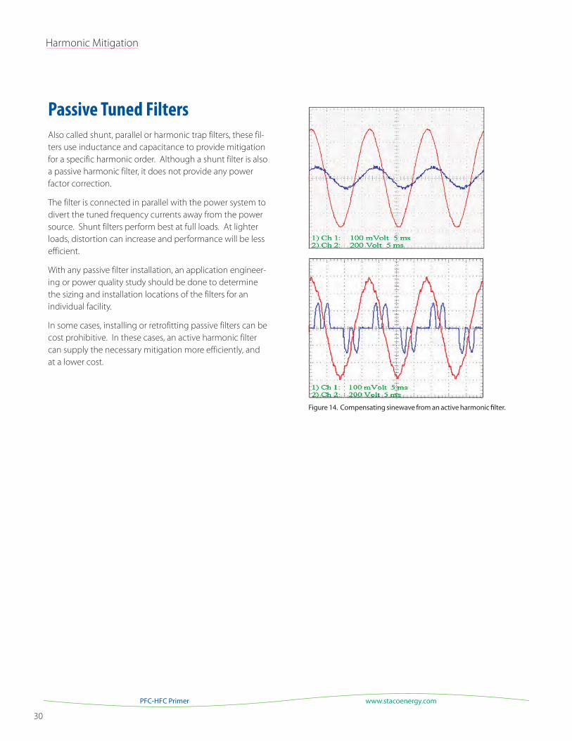
In some cases, installing or retrofitting passive filters can be
cost prohibitive. In these cases, an active harmonic filter
can supply the necessary mitigation more efficiently, and
at a lower cost.
Figure 14. Compensating sinewave from an active harmonic filter.
31
Staco Energy Products Co.
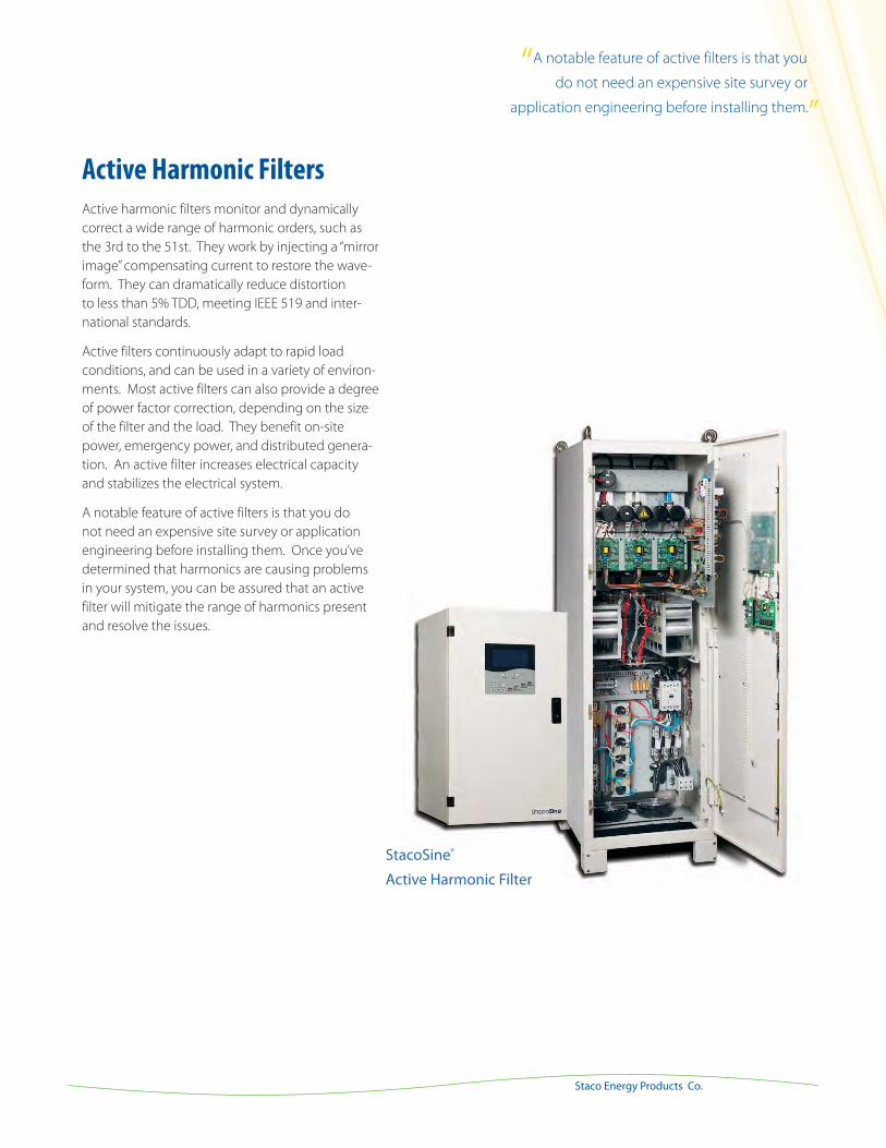
Active Harmonic Filters
Active harmonic filters monitor and dynamically
correct a wide range of harmonic orders, such as
the 3rd to the 51st. They work by injecting a “mirror
image” compensating current to restore the wave-
form. They can dramatically reduce distortion
to less than 5% TDD, meeting IEEE 519 and inter-
national standards.
Active filters continuously adapt to rapid load
conditions, and can be used in a variety of environ-
ments. Most active filters can also provide a degree
of power factor correction, depending on the size
of the filter and the load. They benefit on-site
power, emergency power, and distributed genera-
tion. An active filter increases electrical capacity
and stabilizes the electrical system.
A notable feature of active filters is that you do
not need an expensive site survey or application
engineering before installing them. Once you’ve
determined that harmonics are causing problems
in your system, you can be assured that an active
filter will mitigate the range of harmonics present
and resolve the issues.
StacoSine®
Active Harmonic Filter
“A notable feature of active filters is that you...
do not need an expensive site survey or...
application engineering before installing them.”
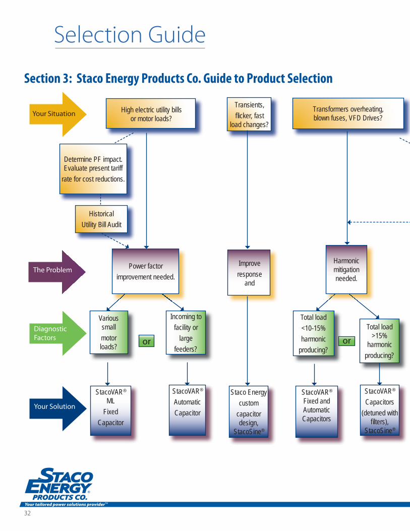
High electric utility bills or motor loads?
Transformers overheating, blown fuses, VFD Drives?
Transients, flicker, fast
load changes?
Staco Energy custom
capacitor design,
StacoSine®
StacoVAR® ML
Fixed Capacitor
StacoVAR®
Automatic Capacitor
Improve response
and
Determine PF impact. Evaluate present tariff
rate for cost reductions.
HistoricalUtility Bill Audit
Various small motor loads?
Incoming to facility or
largefeeders?
or
Total load <10-15% harmonic
producing?
Total load >15%
harmonic producing?
or
StacoVAR® Fixed and Automatic Capacitors
StacoVAR® Capacitors
(detuned with filters),
StacoSine®
Your Situation
The Problem
Diagnostic Factors
Your Solution
Power factor improvement needed.
Harmonic mitigation needed.
Selection Guide
Section 3: Staco Energy Products Co. Guide to Product Selection
32
Your tailored power solutions providerTM
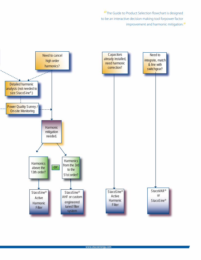
Need to cancel high order
harmonics?
Capacitors already installed, need harmonic
correction?
Need to integrate, match
& line with switchgear?
Harmonics above the
13th order?or
StacoSine® Active
Harmonic Filter
StacoSine® AHF or custom
engineered tuned filter
system
Detailed harmonic analysis (not needed to
size StacoSine®.)
Power Quality Survey / On-site Monitoring
StacoSine® Active
Harmonic Filter
StacoVAR® or
StacoSine®
Harmonic mitigation needed.
Harmonics from the 3rd
to the 51st order?
“The Guide to Product Selection flowchart is designed
to be an interactive decision making tool forpower factor
improvement and harmonic mitigation.”
A G u i d e t o P o w e r Fa c t o r & H a r m o n i c s
www.stacoenergy.com
34
Selection Guide
www.stacoenergy.comPFC-HFC Primer
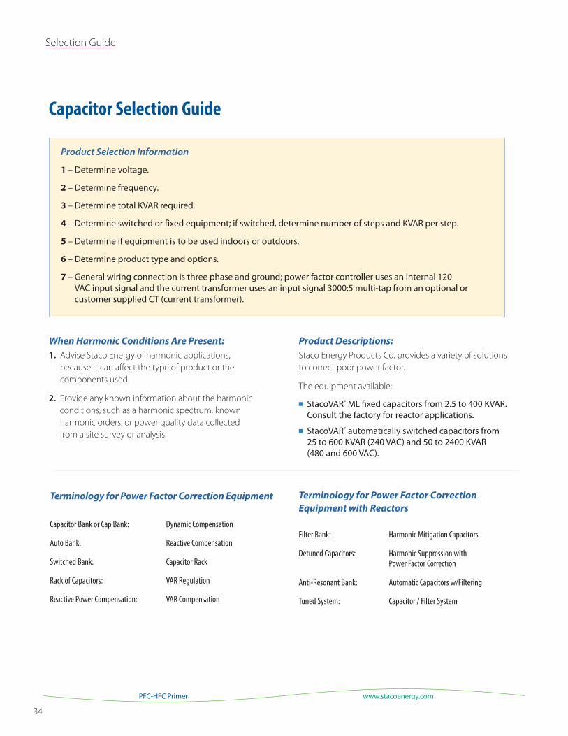
Product Selection Information
1 – Determine voltage.
2 – Determine frequency.
3 – Determine total KVAR required.
4 – Determine switched or fixed equipment; if switched, determine number of steps and KVAR per step.
5 – Determine if equipment is to be used indoors or outdoors.
6 – Determine product type and options.
7 – General wiring connection is three phase and ground; power factor controller uses an internal 120 VAC input signal and the current transformer uses an input signal 3000:5 multi-tap from an optional or customer supplied CT (current transformer).
Capacitor Selection Guide
Product Descriptions:
Staco Energy Products Co. provides a variety of solutions
to correct poor power factor.
The equipment available:
StacoVAR® ML fixed capacitors from 2.5 to 400 KVAR. Consult the factory for reactor applications.
StacoVAR® automatically switched capacitors from 25 to 600 KVAR (240 VAC) and 50 to 2400 KVAR (480 and 600 VAC).
When Harmonic Conditions Are Present:
1. Advise Staco Energy of harmonic applications,
because it can affect the type of product or the
components used.
2. Provide any known information about the harmonic
conditions, such as a harmonic spectrum, known
harmonic orders, or power quality data collected
from a site survey or analysis.
Terminology for Power Factor Correction Equipment
Capacitor Bank or Cap Bank: Dynamic Compensation
Auto Bank: Reactive Compensation
Switched Bank: Capacitor Rack
Rack of Capacitors: VAR Regulation
Reactive Power Compensation: VAR Compensation
Terminology for Power Factor Correction
Equipment with Reactors
Filter Bank: Harmonic Mitigation Capacitors
Detuned Capacitors: Harmonic Suppression with Power Factor Correction
Anti-Resonant Bank: Automatic Capacitors w/Filtering
Tuned System: Capacitor / Filter System
A G u i d e t o P o w e r Fa c t o r & H a r m o n i c s 35
Staco Energy Products Co.
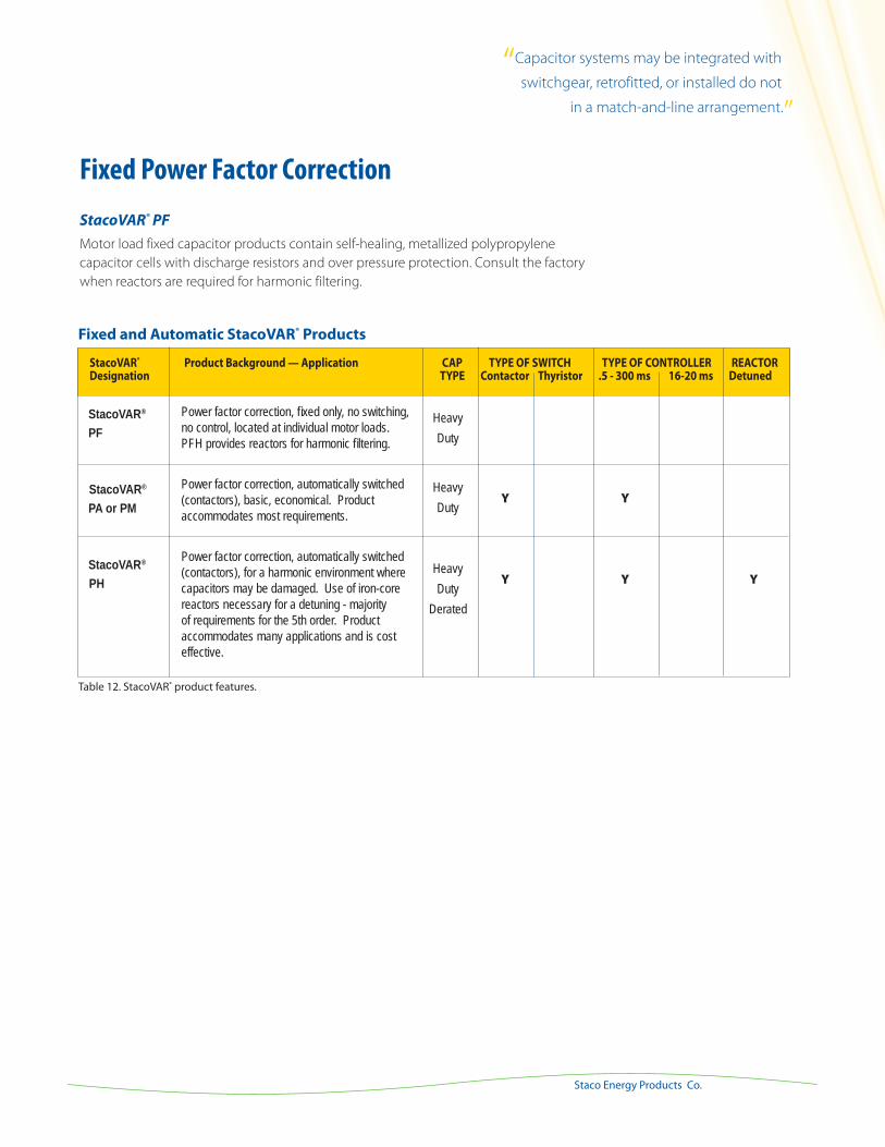
Fixed Power Factor Correction
StacoVAR® PF Motor load fixed capacitor products contain self-healing, metallized polypropylene
capacitor cells with discharge resistors and over pressure protection. Consult the factory
when reactors are required for harmonic filtering.
Y
StacoVAR® PF StacoVAR®
PA or PM
StacoVAR® PH
StacoVAR® Product Background — Application CAP TYPE OF SWITCH TYPE OF CONTROLLER REACTOR Designation TYPE Contactor Thyristor .5 - 300 ms 16-20 ms Detuned
Table 12. StacoVAR® product features.
Fixed and Automatic StacoVAR® Products
Power factor correction, fixed only, no switching, no control, located at individual motor loads. PFH provides reactors for harmonic filtering.
Power factor correction, automatically switched (contactors), basic, economical. Product accommodates most requirements.
Power factor correction, automatically switched (contactors), for a harmonic environment where capacitors may be damaged. Use of iron-core reactors necessary for a detuning - majority of requirements for the 5th order. Product accommodates many applications and is cost effective.
HeavyDuty
HeavyDuty
HeavyDuty
Derated
Y
Y
Y
Y
“Capacitor systems may be integrated with
switchgear, retrofitted, or installed do not
in a match-and-line arrangement.”
36
Selection Guide
www.stacoenergy.comPFC-HFC Primer
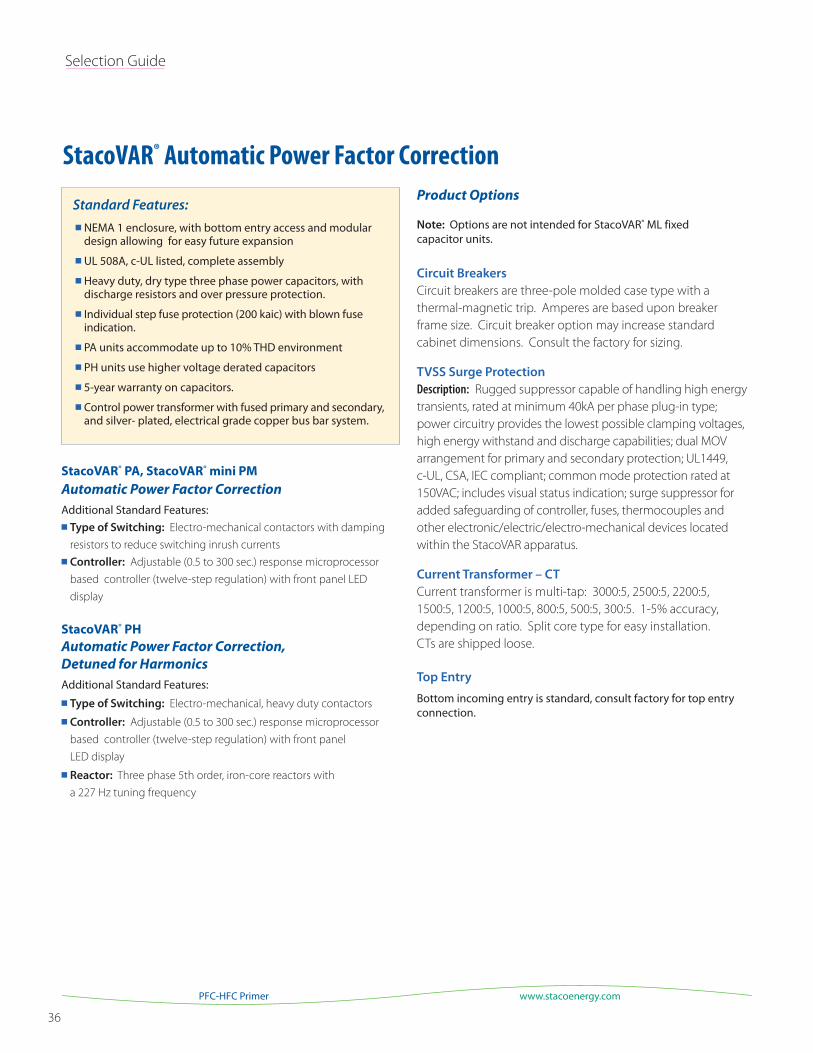
Standard Features:
StacoVAR® PA, StacoVAR® mini PM Automatic Power Factor Correction
Additional Standard Features: Type of Switching: Electro-mechanical contactors with damping
resistors to reduce switching inrush currents
Controller: Adjustable (0.5 to 300 sec.) response microprocessor
based controller (twelve-step regulation) with front panel LED
display
StacoVAR® PH Automatic Power Factor Correction,
Detuned for Harmonics
Additional Standard Features:
Type of Switching: Electro-mechanical, heavy duty contactors
Controller: Adjustable (0.5 to 300 sec.) response microprocessor
based controller (twelve-step regulation) with front panel
LED display
Reactor: Three phase 5th order, iron-core reactors with
a 227 Hz tuning frequency
Product Options
Note: Options are not intended for StacoVAR® ML fixed capacitor units.
Circuit Breakers
Circuit breakers are three-pole molded case type with a
thermal-magnetic trip. Amperes are based upon breaker
frame size. Circuit breaker option may increase standard
cabinet dimensions. Consult the factory for sizing.
TVSS Surge Protection
Description: Rugged suppressor capable of handling high energy
transients, rated at minimum 40kA per phase plug-in type;
power circuitry provides the lowest possible clamping voltages,
high energy withstand and discharge capabilities; dual MOV
arrangement for primary and secondary protection; UL1449,
c-UL, CSA, IEC compliant; common mode protection rated at
150VAC; includes visual status indication; surge suppressor for
added safeguarding of controller, fuses, thermocouples and
other electronic/electric/electro-mechanical devices located
within the StacoVAR apparatus.
Current Transformer – CT
Current transformer is multi-tap: 3000:5, 2500:5, 2200:5,
1500:5, 1200:5, 1000:5, 800:5, 500:5, 300:5. 1-5% accuracy,
depending on ratio. Split core type for easy installation.
CTs are shipped loose.
Top Entry
Bottom incoming entry is standard, consult factory for top entry connection.
NEMA 1 enclosure, with bottom entry access and modular design allowing for easy future expansion
UL 508A, c-UL listed, complete assembly
Heavy duty, dry type three phase power capacitors, with discharge resistors and over pressure protection.
Individual step fuse protection (200 kaic) with blown fuse indication.
PA units accommodate up to 10% THD environment
PH units use higher voltage derated capacitors
5-year warranty on capacitors.
Control power transformer with fused primary and secondary, and silver- plated, electrical grade copper bus bar system.
StacoVAR® Automatic Power Factor Correction
A G u i d e t o P o w e r Fa c t o r & H a r m o n i c s 37
Staco Energy Products Co.
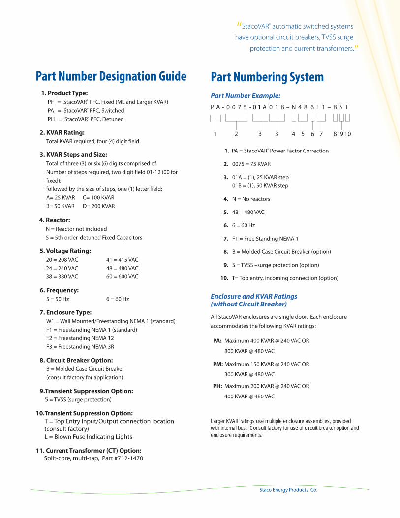
Part Numbering System
Part Number Example:
P A - 0 0 7 5 - 0 1 A 0 1 B – N 4 8 6 F 1 – B S T
1. PA = StacoVAR® Power Factor Correction
2. 0075 = 75 KVAR
3. 01A = (1), 25 KVAR step 01B = (1), 50 KVAR step
4. N = No reactors
5. 48 = 480 VAC
6. 6 = 60 Hz
7. F1 = Free Standing NEMA 1
8. B = Molded Case Circuit Breaker (option)
9. S = TVSS –surge protection (option)
10. T= Top entry, incoming connection (option)
Enclosure and KVAR Ratings (without Circuit Breaker)
All StacoVAR enclosures are single door. Each enclosure
accommodates the following KVAR ratings:
PA: Maximum 400 KVAR @ 240 VAC OR
800 KVAR @ 480 VAC PM: Maximum 150 KVAR @ 240 VAC OR
300 KVAR @ 480 VAC PH: Maximum 200 KVAR @ 240 VAC OR
400 KVAR @ 480 VAC
Larger KVAR ratings use multiple enclosure assemblies, provided with internal bus. Consult factory for use of circuit breaker option and enclosure requirements.
Part Number Designation Guide 1. Product Type: PF = StacoVAR® PFC, Fixed (ML and Larger KVAR) PA = StacoVAR® PFC, Switched PH = StacoVAR® PFC, Detuned
2. KVAR Rating: Total KVAR required, four (4) digit field
3. KVAR Steps and Size: Total of three (3) or six (6) digits comprised of: Number of steps required, two digit field 01-12 (00 for fixed); followed by the size of steps, one (1) letter field: A= 25 KVAR C= 100 KVAR B= 50 KVAR D= 200 KVAR
4. Reactor: N = Reactor not included 5 = 5th order, detuned Fixed Capacitors
5. Voltage Rating: 20 = 208 VAC 41 = 415 VAC 24 = 240 VAC 48 = 480 VAC 38 = 380 VAC 60 = 600 VAC
6. Frequency: 5 = 50 Hz 6 = 60 Hz
7. Enclosure Type: W1 = Wall Mounted/Freestanding NEMA 1 (standard) F1 = Freestanding NEMA 1 (standard) F2 = Freestanding NEMA 12 F3 = Freestanding NEMA 3R
8. Circuit Breaker Option: B = Molded Case Circuit Breaker (consult factory for application)
9. Transient Suppression Option: S = TVSS (surge protection)
10. Transient Suppression Option: T = Top Entry Input/Output connection location (consult factory) L = Blown Fuse Indicating Lights
11. Current Transformer (CT) Option: Split-core, multi-tap, Part #712-1470
109876543321
“StacoVAR® automatic switched systems
have optional circuit breakers, TVSS surge
protection and current transformers.”
38
Selection Guide
www.stacoenergy.comPFC-HFC Primer
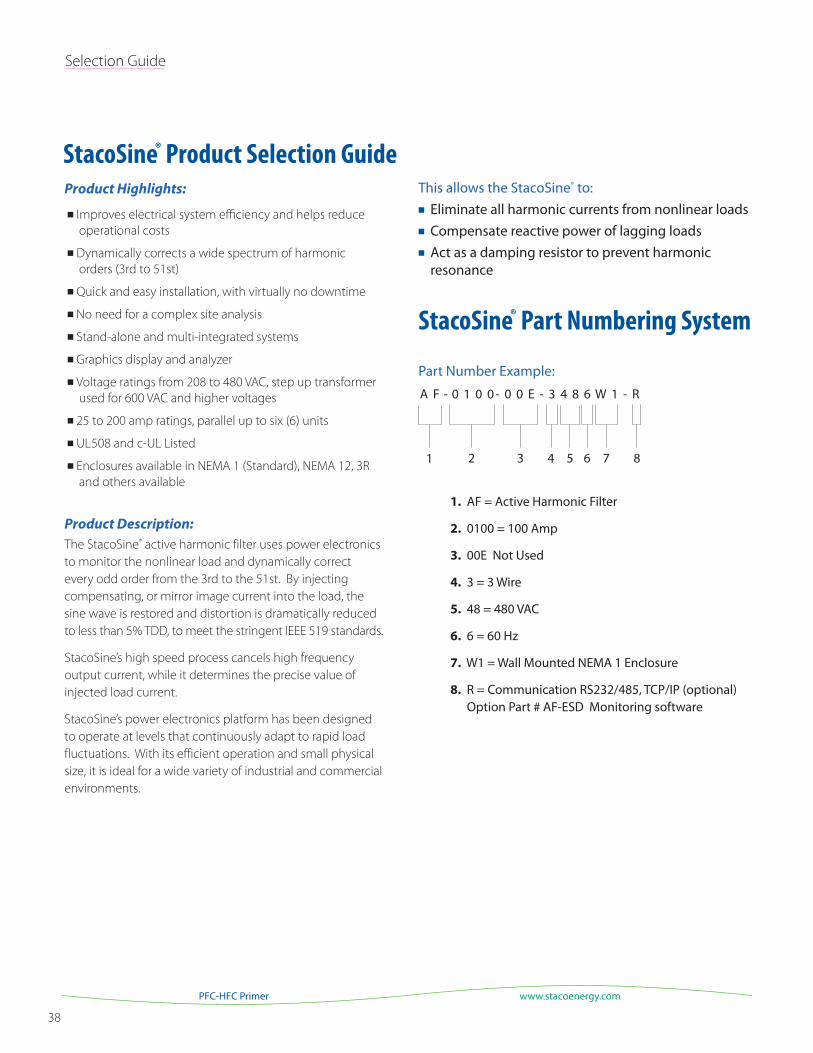
This allows the StacoSine® to: Eliminate all harmonic currents from nonlinear loads Compensate reactive power of lagging loads Act as a damping resistor to prevent harmonic resonance
StacoSine® Part Numbering System
Part Number Example:
A F - 0 1 0 0 - 0 0 E - 3 4 8 6 W 1 - R
1. AF = Active Harmonic Filter
2. 0100 = 100 Amp
3. 00E Not Used
4. 3 = 3 Wire
5. 48 = 480 VAC
6. 6 = 60 Hz
7. W1 = Wall Mounted NEMA 1 Enclosure
8. R = Communication RS232/485, TCP/IP (optional) Option Part # AF-ESD Monitoring software
Product Highlights:
Improves electrical system efficiency and helps reduce
operational costs
Dynamically corrects a wide spectrum of harmonic
orders (3rd to 51st)
Quick and easy installation, with virtually no downtime
No need for a complex site analysis
Stand-alone and multi-integrated systems
Graphics display and analyzer
Voltage ratings from 208 to 480 VAC, step up transformer
used for 600 VAC and higher voltages
25 to 200 amp ratings, parallel up to six (6) units
UL508 and c-UL Listed
Enclosures available in NEMA 1 (Standard), NEMA 12, 3R
and others available
Product Description:
The StacoSine® active harmonic filter uses power electronics
to monitor the nonlinear load and dynamically correct
every odd order from the 3rd to the 51st. By injecting
compensating, or mirror image current into the load, the
sine wave is restored and distortion is dramatically reduced
to less than 5% TDD, to meet the stringent IEEE 519 standards.
StacoSine’s high speed process cancels high frequency
output current, while it determines the precise value of
injected load current.
StacoSine’s power electronics platform has been designed
to operate at levels that continuously adapt to rapid load
fluctuations. With its efficient operation and small physical
size, it is ideal for a wide variety of industrial and commercial
environments.
StacoSine® Product Selection Guide
87654321
A G u i d e t o P o w e r Fa c t o r & H a r m o n i c s 39
Staco Energy Products Co.
Part Number Designation Guide
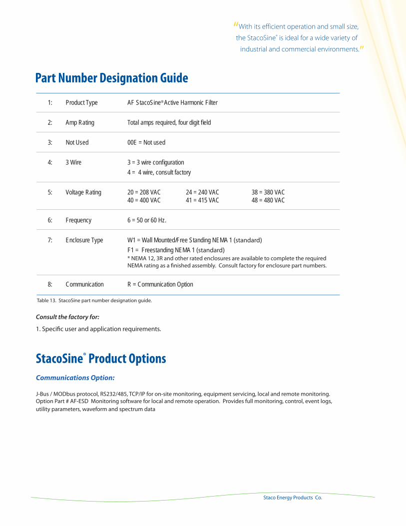
Consult the factory for:
1. Specific user and application requirements.
StacoSine® Product Options
Communications Option:
J-Bus / MODbus protocol, RS232/485, TCP/IP for on-site monitoring, equipment servicing, local and remote monitoring. Option Part # AF-ESD Monitoring software for local and remote operation. Provides full monitoring, control, event logs, utility parameters, waveform and spectrum data
1: Product Type AF StacoSine® Active Harmonic Filter
2: Amp Rating Total amps required, four digit field
3: Not Used 00E = Not used
4: 3 Wire 3 = 3 wire configuration 4 = 4 wire, consult factory
5: Voltage Rating 20 = 208 VAC 24 = 240 VAC 38 = 380 VAC 40 = 400 VAC 41 = 415 VAC 48 = 480 VAC
6: Frequency 6 = 50 or 60 Hz.
7: Enclosure Type W1 = Wall Mounted/Free Standing NEMA 1 (standard) F1 = Freestanding NEMA 1 (standard) * NEMA 12, 3R and other rated enclosures are available to complete the required NEMA rating as a finished assembly. Consult factory for enclosure part numbers.
8: Communication R = Communication Option
Table 13. StacoSine part number designation guide.
“With its efficient operation and small size,
the StacoSine® is ideal for a wide variety of
industrial and commercial environments.”
40
Appendix A
www.stacoenergy.comPFC-HFC Primer
Appendix A
C1 + C2
C1 +
C2 +
C3 +

Staco Energy Products Co.
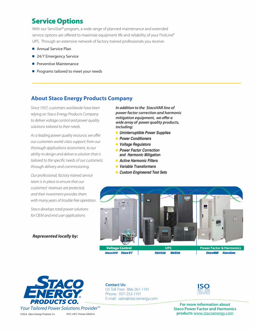
Since 1937, customers worldwide have been
relying on Staco Energy Products Company
to deliver voltage control and power quality
solutions tailored to their needs.
As a leading power quality resource, we offer
our customers world-class support; from our
thorough applications assessment, to our
ability to design and deliver a solution that is
tailored to the specific needs of our customers;
through delivery and commissioning.
Our professional, factory trained service
team is in place to ensure that our
customers’ revenues are protected,
and their investment provides them
with many years of trouble free operation.
Staco develops total power solutions
for OEM and end user applications.
In addition to the StacoVAR line of power factor correction and harmonic mitigation equipment, we offer a wide array of power quality products, including:
Uninterruptible Power Supplies Power Conditioners Voltage Regulators Power Factor Correction and Harmonic Mitigation
Active Harmonic Filters Variable Transformers Custom Engineered Test Sets
About Staco Energy Products Company
Your Tailored Power Solutions ProviderTM
©2014, Staco Energy Products Co. PFC HFC Primer-042514
Represented locally by:
Contact Us:US Toll Free: 866-261-1191Phone: 937-253-1191E-mail: [email protected]
For more information about Staco Power Factor and Harmonics
products www.stacoenergy.com
With our ServiStar® program, a wide range of planned maintenance and extended
service options are offered to maximize equipment life and reliability of your FirstLine®
UPS. Through an extensive network of factory trained professionals you receive:
Annual Service Plan
24/7 Emergency Service
Preventive Maintenance
Programs tailored to meet your needs
Service Options
9001 : 2008CERTIFIED
ISO