power electronics
TRANSCRIPT

Efficiency Comparison of Power Electronic Convertersused in Grid-Connected Permanent-Magnet Wind
Energy Conversion System Based on SemiconductorsPower Losses
by
Md. Arifujjaman and L. Chang
REPRINTED FROM
WIND ENGINEERINGVOLUME 35, NO. 4, 2011
MULTI-SCIENCE PUBLISHING COMPANY5 WATES WAY • BRENTWOOD • ESSEX CM15 9TB • UKTEL: +44(0)1277 224632 • FAX: +44(0)1277 223453E-MAIL: [email protected] • WEB SITE: www.multi-science.co.uk

Efficiency Comparison of Power ElectronicConverters used in Grid-Connected Permanent-Magnet Wind Energy Conversion System Based onSemiconductors Power Losses
Md. Arifujjaman, Post Doctoral Fellow, and L. Chang, ProfessorDepartment of Electrical and Computer Engineering, University of New BrunswickFredericton, NB, Canada, E3B 5A3E-mail: [email protected]
WIND ENGINEERING VOLUME 35, NO. 4, 2011 PP 445-464 445
ABSTRACTAn efficiency comparison of power converters is presented for a permanent magnet
generator based grid-connected wind energy conversion system. The power converters
examined are: the intermediate boost converter (IBC), the intermediate buck-boost
converter (IBBC), the back-to-back converter (BBC) and the matrix converter (MC). The
aim is to determine which power electronic converter yields the highest efficiency in terms
of power losses of the semiconductor devices with the varying wind speeds. In view of this, a
furled wind turbine model is developed that generates power for different wind speeds.
Afterwards, a relation between the wind speed and power loss is established to evaluate the
efficiency of the power electronic converters for discrete wind speeds. The power loss model
presented in this paper has taken into account the conduction and switching losses of the
semiconductor devices within each converter. Simulation results are presented showing the
power loss characteristics with the variation in wind speeds. Finally, with regard to the
global efficiency for the power electronic converters of the considered wind speed regime,
the IBC is found to be the most favourable choice considering the typical wind conditions
encountered by a wind energy conversion system operating at the kWatt level.
1. NOMENCLATURESθ : Furling angle
d : Duty cycle of the boost and buck-boost converter
ESR : Rated off-state switching loss energy of the diode
EON, EOFF : Rated on and off-state switching loss energy of the IGBT respectively
fWT , fSW : Frequency of the wind turbine rotor and switching frequency of the
semiconductors respectively
Ir,d, Ir,i : Reference commutation current od diode and IGBT respectively
rd, rce : On-state resistance of the diode and IGBT respectively
Vf0, Vce0 : On-state voltage of the Diode and IGBT respectively
Vr,d, Vr,i : Reference commutation voltage of the diode and IGBT respectively
2. INTRODUCTIONGrid-connected wind energy conversion system (WECS) is a cost effective renewable
technology and provides a continuously growing contribution to climate change goals, energy

diversity and security. However, the most important aspect for connecting a WECS with the
electric grid requires a power electronic converter (PEC) that allows variable-speed operation,
reduces mechanical stress, and increases efficiency. Among various performances and design
criteria for the converter, the overall efficiency is one of the most significant factors because of
a growing concern regarding the energy savings and cost. However, a considerable lack in
comparison of a series of converters is observed in the previous literatures that practically
discussed with the precise model of semiconductor devices power loss that varies with the
wind speed and finally, the global efficiency of the converters in the wind energy domain.
The PECs are composed of semiconductor devices and indeed, power losses occur during
operation. Moreover, as the PECs are connected to a wind turbine; the power losses will vary with
the wind speeds. As a result, while calculating the efficiency of a converter, one should also
consider the variation of the losses for each wind speed to clarify the effectiveness of a specific
converter for the entire wind speed regime. A calculation of converter efficiency for a given
operating condition is performed in [1–19] in terms of the total semiconductor power losses.
However, either calculating converter efficiency or individual semiconductor power loss model
lacks a considerable valid justification. This is because, firstly, a non-linear loss model approach is
unable to reflect the switching losses of the semiconductor devices, which could be a dominant
factor during the high switching state [1–8]. Secondly, power loss model based on the data provided
by the manufacturers is ambiguous and pessimistic [9–13]. Thirdly, physics-based simulation
models of semiconductor devices power losses requires implicit integration methods, leading to an
increased simulation time. Furthermore, it requires detail knowledge of the dimensions of the
devices [14, 15]. There have been numerous other efforts for modeling the power losses of
converters used in wind turbine systems. In [16–19] presented the concept of maximum device
rating power loss model of the converter, however, switching losses is often ignored.
Based on the above discussions, it can be asserted that most of the attempts for the
converter efficiency calculation in terms of the power loss model have been developed based
on several assumptions and often neglected a fraction of the entire converter power losses.
This discrepancy could affect the preference of an efficient grid-connected WECS that is in a
great need for high penetration of the wind power. As a consequence, this research aims at
advancing the use of grid-connected WECS by modeling the wind turbine (WT) power
generation and power losses of the semiconductor devices for the most useable converters
with the variation in wind speeds. Based on the power generation and loss for individual wind
speed, a global efficiency is calculated for the considered wind speed regime of each
converter and an efficient converter is determined.
This paper is organized as follows: Followed by a detail literature review in the second
section, the selected converter systems are presented in the third section. The fourth section
describes the global efficiency calculation of the converters. The modeling approach to obtain
the power generation of the furled WT along with the operating conditions is described in the
fifth section, while the sixth section contains the mathematical model for power loss
calculations in the semiconductor devices. Simulation results and discussions are presented
and discussed in the seventh section and finally, the findings of the investigations are
highlighted in the conclusions.
3. POWER ELECTRONIC CONVERTERS FOR GRID CONNECTED WIND ENERGYCONVERSION SYSTEMThe design concept of wind turbine has progressed from induction generator based fixed
speed, flapping/passive pitching-controlled drive train with gearbox to permanent magnet
generator (PMG)-based variable-speed, furling/soft stall-controlled systems with or without
446 EFFICIENCY COMPARISON OF POWER ELECTRONIC CONVERTERS USED IN GRID-CONNECTED
PERMANENT-MAGNET WIND ENERGY CONVERSION SYSTEM BASED ON SEMICONDUCTORS POWER LOSSES

gearbox. The PMG-based grid connected WECS is favorable due to the flexibility in design
which allows smaller and lighter diameter, higher output level may be achieved without the
need to increase generator size, lower maintenance and operating costs and most
importantly, eliminates the need for separate excitation or cooling systems. Fig. 1 has shown
the four potential converters that have been selected for study and which are very common
with the PMG-based WECS. Firstly, an intermediate boost converter (IBC), employs a 3-phase
WIND ENGINEERING VOLUME 35, NO. 4, 2011 447
Figure 1: Typical power electronic converters a) Intermediate boost converter (IBC), b) Intermediate
buck-boost converter (IBBC), c) Back-to-back converter (BBC), d) Matrix converter (MC)

bridge rectifier, a boost converter and a grid-connected pulse width modulated (PWM)
inverter (Fig. 1a) [10, 20]. Secondly, intermediate buck-boost converter (IBBC), employs a 3-
phase bridge rectifier, a buck-boost converter and a grid-connected PWM inverter (Fig. 1b) [21,
22]. Thirdly, back-to-back converter (BBC), composed of a rectifier, DC link and a PWM
inverter (Fig. 1c) [23, 24]. And lastly, matrix converter (MC), employs 9 bidirectional switches
for three phase input and output connection between the generator and grid (Fig. 1d) [25, 26].
Each of the converters has their own advantages and disadvantages and a brief literature
review can be found in [27].
4. EFFICIENCY CALCULATIONIn order to calculate the efficiency of the converters, the relation between the wind speed and
power generation/loss for each wind speed is needed. Once the power generation is known
for discrete wind speed using Section V, the total power generation, Pg is expressed as
(1)
where wi represents a particular wind speed within the wind speed regime and Pg,i (wi) is the
power generation for wi wind speed. . The power loss for the wind speed of each converter can
be found as described in Section VI and the total power loss, Pl is mathematically expressed as
(2)
The global efficiency, η of the converters is then calculated as,
(3)
5. WIND TURBINE MODELA wind turbine can be characterized by the non-dimensional curve of power coefficient, Cp as
a function of tip speed ratio, λ, where, λ is given in terms of rotor speed, ωs (rad/s), wind speed,
w (m/s), and rotor radius, Rw (m) as
(4)
The relationship between Cp and λ can be approximated by a quartic equation. In this
research, the curve is obtained from the literature [28]. A model for Cp as a function of λ is
calculated and the curve generated by the approximate model and the actual data are
presented in Fig. 2a. Statistical analysis shows that the R2 value of the model is 99.8% and the
p-value from the chi-square goodness-of-fit test is less than 0.0001, which shows that the
predicted model for Cp with the fitted coefficients is acceptable. The resulting equation is
found to be
(5)
The curve between wind speed and furling angle is derived from published data [29]. An
approximate model is used to determine the relation between wind speeds and furling angle.
It is found that a fifth order model is sufficient to represent the relationship. The R2 value and
the p-value from the chi-square goodness-of-fit test of the expected model are found to be
C p λ λ λ λ λ( ) = − + − +0 00044 0 012 0 097 0 2 0 114 3 2. . . . .
λ ω= R
ww s
η =−
×P P
P
g l
g
100%
P P wl l i i
i w
wn
= ( )=∑ ,
1
P P wg g i i
i w
wn
= ( )=∑ ,
1
448 EFFICIENCY COMPARISON OF POWER ELECTRONIC CONVERTERS USED IN GRID-CONNECTED
PERMANENT-MAGNET WIND ENERGY CONVERSION SYSTEM BASED ON SEMICONDUCTORS POWER LOSSES

98.19% and less than 0.0001 respectively, thus validating the modeling approach. The modeling
equation for the wind turbine is determined as
(6)
where θ is the furling angle in degree. The actual data and approximated model curve are
represented in Fig. 2b.
The output power of the wind turbine can be expressed as
(7)
where ρ is the air density (kg.m�3) and A is the rotor rotational area, i.e., πRw2.
When the wind speed increases, wind turbines yaw to an angle θ along its horizontal axis
because of the furling action. The effective wind velocity at the rotor plane in that case will be
P AC waero p= ( )0 5 3. ρ λ
θ = − + − + +0 00019282 011317 0 21115 1 179 1 4072 3 16285 4 3 2. . . . . .w w w w w
WIND ENGINEERING VOLUME 35, NO. 4, 2011 449
Figure 2: a) Power coefficient as a function of tip speed ratio, b) Furling angle versus wind speed

wcosθ [30]. Incorporating the furling action, the theoretical power of the wind turbine can be
written from (7) as
(8)
Equation (8) represents the power for varying wind speed of the wind turbine rotor without
accounting for maximum power production. Maintaining a constant optimum tip speed ratio
can ensure the maximum power production. It should be noted that the value of the optimum
tip speed ratio varies from one turbine to another. The relation between power coefficient and
tip speed ratio used in this study requires to assume an optimum tip speed ratio of 7 for the
wind turbine and thus (8) is expressed in terms of the optimum power coefficient as
(9)
where Cp,OPT(λ) is the optimum value of power co-efficient at the optimum TSR.
The theoretical maximum power of the wind turbine described in (9) serves as the dynamic
power reference for all four converters. In the variable-speed systems the speed increases
linearly with the wind speed up to the rated speed, which in this case is reached at 13 m/s. And
from rated to cut-out wind speed, i.e., 17 m/s the turbine speed is lowered using furling action.
The current at the output of the generator is determined by the power generation by the WT
and the generator voltage.
6. POWER LOSS MODELA mathematical model of the power losses in the semiconductor devices (diodes/IGBTs) is
required in order to compare the efficiency of the converters. The losses for the
semiconductor devices are strongly dependent on the voltage and current waveforms.
Simplified analytical derivation of voltage and current equations associated with the
individual semiconductor devices are derived to determine the power losses. The power loss
model presented in this investigation focus on the losses generated during the conduction and
switching states of the semiconductor devices.
6.1. Intermediate Boost Converter (IBC)For the 3-phase diode bridge rectifier, the losses are calculated for a single diode from the known
voltage and current equations. It is assumed that the current and voltage in the 3-phase diode
bridge rectifier are equally distributed in the diodes. As a consequence, considering each diode
current, Id1IBC
and forward voltage, Vfthe conduction losses, Pc1,d-RIBC
for the diode is expressed as [31]
(10)
Under the assumption of a linear loss model for the diodes, the switching loss in each diode,
Ps1,d-RIBC
is given by [32]
(11)
where VdcIBC
and IdcIBC
are the output current and voltage of the bridge rectifier.
The total losses of the 3-phase diode bridge rectifier, Pt,d-RIBC
is expressed as
(12)P P Pt d RIBC
c d RIBC
s d RIBC
, , ,− − −= +( )6 1 1
P f EV
V
I
Is d R
IBCWT SR
dcIBC
r d
dcIBC
r d1,
, ,
. .− =
P V Ic d RIBC
f dIBC
1 1, − =
P = 0.5R AC wmax w p,OPT
3λ θ( )( ) cos
P AC waero p= ( )( )0 53
. cosρ λ θ
450 EFFICIENCY COMPARISON OF POWER ELECTRONIC CONVERTERS USED IN GRID-CONNECTED
PERMANENT-MAGNET WIND ENERGY CONVERSION SYSTEM BASED ON SEMICONDUCTORS POWER LOSSES

The conduction and switching loss of the boost converter is calculated by assuming an ideal
inductor (LDIBC
) at the input. For a boost converter, the IGBT is turned on for a duration d,
while the diode conducts for the duration (1–d). The on-state current of the IGBT is the input
current, IdcIBC
, while the inverter input current, Idc2IBC
is given by [33]
(13)
The conduction loss for the diode, Pc,d-B
IBC and IGBT, Pc,i-B
IBC can be obtained by multiplying
their on-state voltage and current with the respective duty cycle and is given by [33]
(14)
(15)
The actual commutation voltage and current for the boost converter are the DC link voltage,
Vdc2IBC
and input current to the converter, IdcIBC
. The switching loss of the diode, Ps,d-BIBC
and
IGBT, Ps,i-BIBC
in the boost converter are given by [33]
(16)
(17)
The sum of (14) to (17) gives the total losses, Pt,(d+i)-BIBC
(18)
With the exclusion of snubber circuit, the PWM inverter consists of 6 IGBTs and 6 anti parallel
diodes. The conduction losses of a diode, Pc1,d-IIBC
and IGBT, Pc1,i-IIBC
for the inverter can be
expressed as [34],
(19)
(20)
where IomIBC
is the maximum value of the sinusoidal output current, iomIBC
.
For the inverter, the commutation voltage and current are the DC link voltage and output
current. An approximated solution for the switching loss of a diode, Ps1,d-IIBC
and IGBT, Ps1,i-IIBC
is
given by [35]
(21)
(22)
The loss, Pt,(d+i)-IIBC
of the PWM inverter is obtained as the sum of (19) to (22) and expressed by
(23), while the total loss, PtIBC
for the IBC is expressed by (24).
P f E EV
V
I
Is i I
IBCsw ON OFF
dcIBC
r i
omIBC
r i1
21,
, ,− = +[ ]π
P f EV
V
I
Is d I
IBCsw SR
dcIBC
r d
omIBC
r d1
21,
, ,− =
π
P r I V Ic i IIBC
ce omIBC
ce omIBC
1
2
0
1
8
1
3
1
2
1
8, − = +
( ) + +
π π
P r I V Ic d IIBC
d omIBC
f omIBC
1
2
0
1
8
1
3
1
2
1
8, − = −
( ) + −
π π
P P P P Pt d i BIBC
c d BIBC
c i BIBC
s d BIBC
s i BIBC
,( ) , , , ,+ − − − − −= + + +
P f E EV
V
I
Is i B
IBCsw ON OFF
dcIBC
r i
dcIBC
r i,
, ,
. .− = +( ) 2
P f EV
V
I
Is d B
IBCsw SR
dcIBC
r d
dcIBC
r d,
, ,
. .− = 2
P I V r I dc i BIBC
dcIBC
ce ce dcIBC
, .− = +( )0
P I V r I dc d BIBC
dcIBC
f d dcIBC
, .− = +( ) −( )0 1
I I ddcIBC
dcIBC
2 1= −( )
WIND ENGINEERING VOLUME 35, NO. 4, 2011 451

(23)
(24)
6.2. Intermediate Buck-Boost Converter (IBBC)Equation (10) and (11) are used to calculate the conduction and switching losses for the 3-
phase bridge rectifier and the total loss, Pt,d-RIBBC
is expressed by (25)
(25)
The relationship between the average inductor current, IL and the output current, Idc2IBBC
for
the continuous mode buck-boost converter is given by
(26)
Average source current, IdcIBBC
is related to the average inductor current, IL by
(27)
The conduction loss for the diode, Pc,d-BBIBBC
and IGBT, Pc,i-BBIBBC
can be expressed as
(28)
(29)
IdcIBBC
serves as the reference commutation current while, Vdc2IBBC
is the reference
commutation voltage of the buck-boost converter. As a result, the switching loss for the diode,
Ps,d-BBIBBC
and IGBT, Ps,i-BBIBBC
is expressed as
(30)
(31)
The sum of (28) to (31) gives the total losses, Pt,(d+i)-BBIBBC
as
(32)
The PWM inverter used for the IBBC maintains the same characteristic as used with IBC. This
conclusion leads that equation (19) to (22) can be used to calculate the conduction and
switching losses for the PWM inverter of the IBBC and is given by (33), and the total loss, PtIBBC
is expressed by (34)
(33)
(34)P P P PtIBBC
t d RIBBC
t d i BBIBBC
t d i IIBBC= + +− + − +( )−, ,( ) ,
P P P P Pt d i IIBBC
c d IIBBC
c i IIBBC
s d IIBBC
s i IIBBC
, , , , ,+( )− − − − −= + + +( )6 1 1 1 1
P P P P Pt d i BBIBBC
c d BBIBBC
c i BBIBBC
s d BBIBBC
s i BBIBBC
,( ) , , , ,+ − − − − −= + + +
P f E EV
V
I
Is i BB
IBBCsw ON OFF
dcIBBC
r i
dcIBBC
r i,
, ,
. .− = +( ) 2
P f EV
V
I
Is d BB
IBBCsw SR
dcIBBC
r d
dcIBBC
r d,
, ,
. .− = 2
P I V rI
dc i BB
IBBCdc ce ce
dcIBBC
, − = +
0
P I dV
dr
I
dc d BB
IBBCdc
IBBC fd
dcIBBC
, − = −( ) +
1 0
2
I I ddcIBBC
L=
− = −( )I I ddcIBBC
L2 1
P P Pt d RIBBC
c d RIBBC
s d RIBBC
, , ,− − −= +( )6 1 1
P P P PtIBC
t d RIBC
t d i BIBC
t d i IIBC= + +− + − +( )−, ,( ) ,
P P P P Pt d i IIBC
c d IIBC
c i IIBC
s d IIBC
s i IIBC
, , , , ,+( )− − − − −= + + +( )6 1 1 1 1
452 EFFICIENCY COMPARISON OF POWER ELECTRONIC CONVERTERS USED IN GRID-CONNECTED
PERMANENT-MAGNET WIND ENERGY CONVERSION SYSTEM BASED ON SEMICONDUCTORS POWER LOSSES

6.3. Back-to-Back Converter (BBC)It is well understood that the modulation algorithm is always unique for a specific
conventional PWM converter regardless of DC-AC or AC-DC operation mode, the model of
conduction and switching losses is also unique to a specific conventional PWM converter as
far as the conditions of physical devices keep unchanged. In view of these the PWM rectifier
results (35) and (36) for the conduction, Pcc1,d-RBBC
and switching loss, Pcc1,i-RBBC
of the anti
parallel diode respectively. In addition, (37) and (38) presents the conduction, Pss1,d-RBBC
and
switching, Pss1,i-RBBC
loss of the IGBT respectively [36].
(35)
(36)
(37)
(38)
where IamBBC
is the maximum value of the PMG line current at the input of the PWM rectifier.
The total loss, Ptt(d+i),-RBBC
for the PWM rectifier is given by
(39)
Assuming the DC link capacitor average voltage is constant and remains in proper
coordination to work the inverter properly. This also implies that the mean capacitor current
is zero so as the power losses of the capacitor. The power loss of the DC link capacitor due to
leakage current is ignored for the time being.
In a similar manner as applied for the PWM inverter power loss calculation of the IBC and
IBBC, (19) to (22) are adapted to calculate the conduction and switching loss for the PWM
inverter of the BBC and the PWM inverter loss, Ptt(d+i),-IBBC
is expressed by (40), while the total
losses, PtBBC
of the BBC is expressed by (41).
(40)
(41)
6.4. Matrix Converter (MC)Since a suitable bidirectional semiconductor switch can be realized using several ways, this
research considered the back-to-back IGBT arrangement as it allows independent control of
the current in both directions within each switch. In this paper, the control method reported
[37] has been employed because of good input current control characteristics under balanced
input voltage conditions. In this analysis, a 3-phase MC is used and a sinusoidal current output
is assumed. The conduction losses of the diode and IGBT for a single phase are presented by
(42) and (43) respectively.
(42)P V I r Ic dMC
f omMC
d omMC
, = + ( )2 20
2
π
P P PtIBBC
tt d i RBBC
t d i IBBC= ++( )− +( )−, ,
P P P P Pt d i IBBC
c d IBBC
c i IBBC
s d IBBC
s i IBBC
, , , , ,+( )− − − − −= + + +( )6 1 1 1 1
P P P P Ptt d i RBBC
cc d RBBC
cc i RBBC
ss d RBBC
ss i RBBC
, , , , ,+( )− − − − −= + + +( )6 1 1 1 1
P f E EV
V
I
Iss i R
BBCsw ON OFF
dcBBC
r i
amBBC
r i1
1,
, ,− = +[ ]π
P f EV
V
I
Iss d R
BBCsw SR
dcBBC
r d
amBBC
r d1
1,
, ,− =
π
P r I V Icc i RBBC
ce amBBC
ce amBBC
1
2
0
1
8
1
3
1
2
1
8, − = +
( ) + +
π π
P r I V Icc d RBBC
d amBBC
f amBBC
1
2
0
1
8
1
3
1
2
1
8, − = −
( ) + −
π π
WIND ENGINEERING VOLUME 35, NO. 4, 2011 453

(43)
where IomBBC
is the maximum value of the line current at the output of the MC.
The switching losses when normalized with the reference voltage and current results (44)
and (45) for the diode and IGBT respectively.
(44)
(45)
where VaBBC
is the maximum value of the line current at the output of the MC.
The total losses of the MC is then found as
(46)
7. RESULTS AND DISCUSSIONSThe analytical calculations illustrated in the above sections were carried out to determine the
total power generation/losses, and afterwards efficiency in four power electronic converters
under varying wind speed conditions. The rated power for the wind turbine is assumed to be
1.5 kW. The inverter switching frequency is considered as 20 kHz and to investigate the worst-
case scenario of the power loss in this numerical simulation study, the modulation index is
assumed unity and load current is assumed in phase with the output voltage. In addition, the
variation of duty cycle of the IBC and IBBC is considered as the maximum value. This is due to
the fact that the semiconductor devices will transmit the maximum indirect power, i.e.,
maximum stress on the devices thus resembles the worst case scenario [38]. The thermal
model of the converters is neglected provided that the heat sink is adequate enough to
maintain the semiconductors proper working. Power wasted in the power supplies for the
control of the converters is also ignored (It may be between 10–20W). The analytical
calculation is based on the EUPEC IGBT module FP15R12W1T4_B3 [39].
Fig. 3 shows the power generation by the wind turbine based on the modeling equations
described in Section 5 and operating from a wind speed of 2 m/s (cut-in) to 17 m/s (cut-out),
while the rated wind speed is 13 m/s. The furling control has been established through the
furling model (6) and effectively reduces the power above rated wind speed. This power
serves as the dynamic power reference for all power electronic converters and summed up to
calculate the total power generation by the WT for the considered wind speed regime.
The conduction and switching losses for the diodes and IGBTs of the IBC, which composed of
a 3-phase diode bridge rectifier, a boost converter and a PWM inverter is presented in Fig. 4a–c
respectively for a similar wind variation. In an analogous fashion, power losses for the IBBC, BBC
and MC are presented through Fig. 5, Fig. 6 and Fig. 7 respectively. The total loss of each
converter is shown in Fig. 8 and can be found by summing up all the losses (conduction and
switching) for each converters. The results of the power losses for the converters show that the
power loss is higher for a low wind speed (12m/s) than for the rated wind speed (13 m/s) except
for the MC and are due to the furling action. The furling angle varies abruptly from 9 m/s to 13
m/s with negligible change close to the maximum speed. Meanwhile, the voltage remains linear
with the wind speed. As a result, the captured aerodynamic power as well as the current are
asymmetrical on either side of the rated wind speed and are reflected on the power loss curve.
P P P P PtIBBC
c dMC
c iMC
s dMC
s iMC= + + +( )3 , , , ,
P f E EV
V
I
Is i
MCsw ON OFF
aMC
r d
amIBBC
r d,
, ,
. .= +( ) 122π
P f EV
V
I
Is d
MCsw SR
aMC
r d
amIBBC
r d,
, ,
. .= 122π
P V I r Ic iMC
ce omMC
ce omMC
, = + ( )2 20
2
π
454 EFFICIENCY COMPARISON OF POWER ELECTRONIC CONVERTERS USED IN GRID-CONNECTED
PERMANENT-MAGNET WIND ENERGY CONVERSION SYSTEM BASED ON SEMICONDUCTORS POWER LOSSES

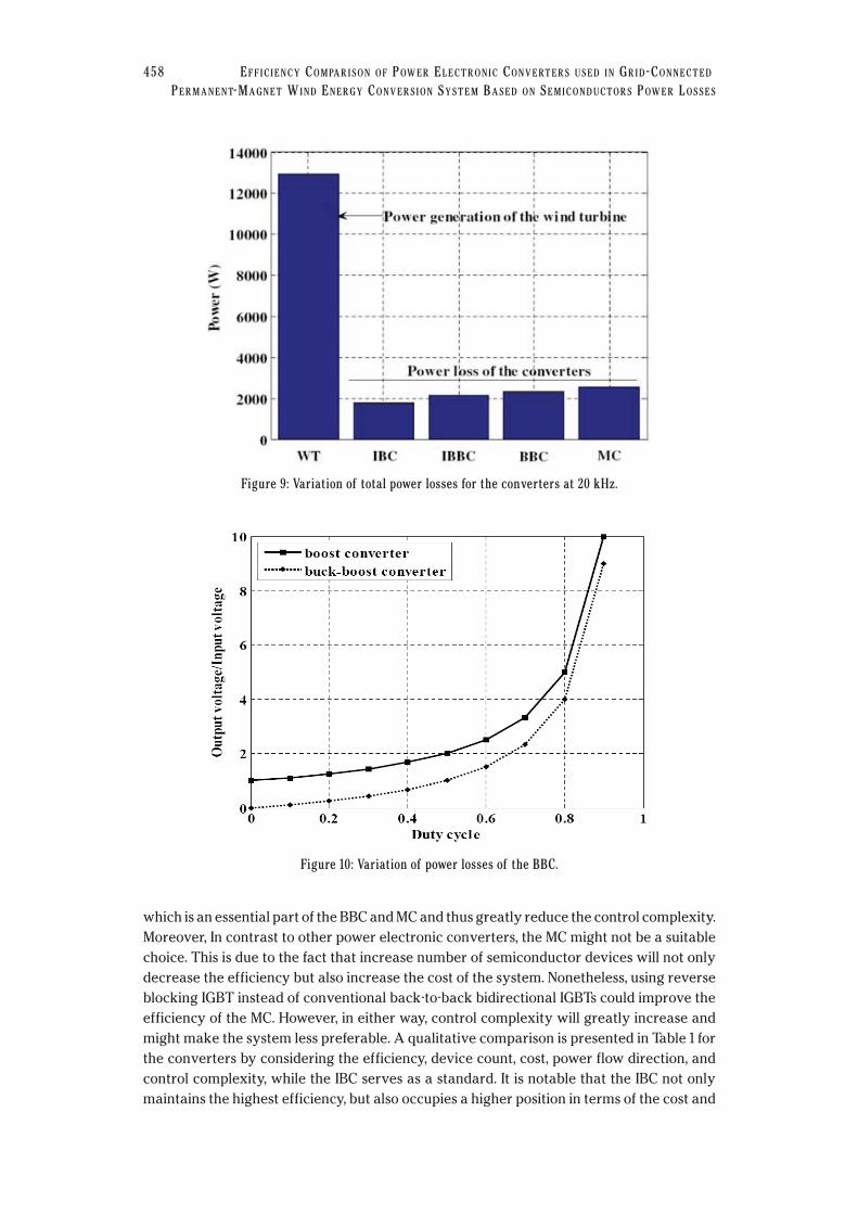
The power generation by the wind turbine and total power loss of the converters within
the considered wind speed regime is shown in Fig. 9. It is obvious that the IBC resulted lower
power losses compared to any other converters. The IBBC exhibits a small amount of higher
losses than the IBC. This is because to achieve the same voltage level, a boost converter
requires less duty cycle than a buck-boost converter and can be seen from Fig. 10. This
implies that due to a higher duty cycle, the conduction losses of the buck-boost converter
will eventually increase and reflect on the total loss calculation for the IBBC. However,
compared to the IBC and IBBC, the BBC and MC have higher power losses due to the
involvement of higher number of semiconductor devices. Furthermore, higher values of
internal resistance of the IGBTs increase the conduction losses and so as the total power
losses of the BBC and MC. In addition, on-state and off-state switching loss energies of the
WIND ENGINEERING VOLUME 35, NO. 4, 2011 455
Figure 3: Variation of power generation with wind speed by the wind turbine.
Figure 4: Variation of power losses with wind speed of the IBC.

IGBTs associated with the BBC and MC increase switching losses, while the off-state
switching loss energy of a diode is lower and the IBC or IBBC adapts a 3-phase bridge
rectifier at the input for the AC–DC conversion. The efficiency calculation of the converters
reveal that the IBC maintains an efficiency of 86%, while the MC has the lowest efficiency of
80%. The IBBC has an efficiency of 83% which is lower in value than the IBC and is due to the
higher conduction losses involve with the buck-boost converter. Compared to the boost
converter of the IBC, IBBC requires higher voltage and current rating components for the
buck-boost converter of the IBBC. The BBC maintains efficiency of 81%, and finally as a
whole, the IBC has received the highest efficiency than any other converters under
consideration. However, before selecting a particular converter, several other issues should
also needs to be taken into consideration. The total number of semiconductor devices
456 EFFICIENCY COMPARISON OF POWER ELECTRONIC CONVERTERS USED IN GRID-CONNECTED
PERMANENT-MAGNET WIND ENERGY CONVERSION SYSTEM BASED ON SEMICONDUCTORS POWER LOSSES
Figure 5: Variation of power losses with wind speed of the IBC.
Figure 6: Variation of power losses with wind speed of the BBC.

associated with the BBC and MC are more than the IBC and IBBC. This signifies that the cost
of the IBC and IBBC is lower than the BBC and MC as more diodes and IGBTs are involved
with these two converters. Furthermore, typically IGBTs are 6.6 times more expensive than
diodes and also supports the cost assumptions. The input voltage phase and amplitude of the
BBC is independent of the generator emf phase and amplitude. This facilitates the reverse
power flow characteristic of the BBC by altering the phase of the generated voltage. The
reverse power flow then can be used to start the wind turbine rotor thus could enhance the
energy generation by a WECS. This bidirectional power flow characteristic is absent in the
IBC and IBBC due to the involvement of rectifier at the input which composed of
unidirectional diodes. On the other hand, inclusion of a 3-phase bridge rectifier with the IBC
and IBBC provide unity power factor capability without using any extra control circuitry,
WIND ENGINEERING VOLUME 35, NO. 4, 2011 457
Figure 7: Variation of power losses with wind speed of the MC.
Figure 8: Variation of power losses with wind speed for the converters.
which is an essential part of the BBC and MC and thus greatly reduce the control complexity.
Moreover, In contrast to other power electronic converters, the MC might not be a suitable
choice. This is due to the fact that increase number of semiconductor devices will not only
decrease the efficiency but also increase the cost of the system. Nonetheless, using reverse
blocking IGBT instead of conventional back-to-back bidirectional IGBTs could improve the
efficiency of the MC. However, in either way, control complexity will greatly increase and
might make the system less preferable. A qualitative comparison is presented in Table 1 for
the converters by considering the efficiency, device count, cost, power flow direction, and
control complexity, while the IBC serves as a standard. It is notable that the IBC not only
maintains the highest efficiency, but also occupies a higher position in terms of the cost and
458 EFFICIENCY COMPARISON OF POWER ELECTRONIC CONVERTERS USED IN GRID-CONNECTED
PERMANENT-MAGNET WIND ENERGY CONVERSION SYSTEM BASED ON SEMICONDUCTORS POWER LOSSES
Figure 9: Variation of total power losses for the converters at 20 kHz.
Figure 10: Variation of power losses of the BBC.

control complexity, however, exhibits unidirectional power flow characteristic. In
conclusion, it is concluded that even though the BBC and MC provides the reverse power
flow characteristic, IBC still holds a better position and could be a suitable choice for high
penetration of wind power.
The emphasis is then given to clarify the converter performances under the influence of
switching frequency. This is of particular importance because the losses of power
electronic converters typically increase with an increase in switching frequency and
subsequently increase the power loss leading to a decrease in the efficiency and vice versa.
For a low switching frequency, however, the ripple in the current is substantial, and there
could be a considerable difference in turn-on and turn-off losses. A trade-off should be
made between the operating point of the switching frequency and the desired
performance of the system.
Fig. 11 and Fig. 12 present the variation of the total power losses with wind speeds of the
converters for a 10 KHz and 30 KHz switching frequency. It is clear that high switching
frequency produce more losses to the converters and vice versa. Corresponding to these
power losses, Fig. 13 and Fig. 14 presents the total power losses for the converters from cut-in to
cut-out wind speed. In either graphs, the IBC still maintains the lowest losses compared to any
other converters. Afterwards, efficiency is calculated and Table 2 presents the variation of the
efficiency with the variation in switching frequency with the IBC@20kHz as a standard. It is
WIND ENGINEERING VOLUME 35, NO. 4, 2011 459
Figure 11: Variation of power losses with wind speed for the converters at 10 kHz
Table 1 Comparison of power electronic converters
Power ElectronicConcerters IBC IBBC BBC MC
Efficiency 86% 83% 81% 80%Device count Diode-7 Diode-7 Diode-12 Diode-18
IGBT-7 IGBT-7 IGBT-12 IGBT-18Cost Low High Higher Highest
Power flow direction Unidirectional Unidirectional Bidirectional BidirectionalControl complexity Low Low High Highest

obvious that the IBC provides a higher efficiency for both 10 kHz and 30 kHz operation.
Furthermore, the efficiency (91%) at 10 kHz switching frequency is 5% more than the
efficiency (86%) that occurred at 20 kHz. On the other hand, the efficiency (80%) at 30 kHz
switching frequency is about 6% less than the efficiency that occurred at 20 kHz. The same
460 EFFICIENCY COMPARISON OF POWER ELECTRONIC CONVERTERS USED IN GRID-CONNECTED
PERMANENT-MAGNET WIND ENERGY CONVERSION SYSTEM BASED ON SEMICONDUCTORS POWER LOSSES
Figure 13: Variation of total power losses for the converters at 10 kHz.
Figure 12: Variation of power losses with wind speed for the converters at 30 kHz.
Table 2 Efficiency variation of power electronic converters with switching frequency
Efficiency
Power Electronic Concerters IBC IBBC BBC MC
10 kHz 91% 88% 87% 84%20 kHz 86% 83% 81% 80%30 kHz 80% 78% 74% 73%

conclusion can be drawn for all the other converters in consideration. This leads to an
imperative observation that operating the system at a lower (higher) switching frequency
either than 20 kHz, will increase (decrease) the power loss without a significant change in the
efficiency. But decrease in switching frequency augments the cost due to the installation of a
filter circuit at the output of the PCS and commence lower order harmonics to the system. In
contrast to the lower switching frequency (10 kHz), a higher switching frequency (30 kHz)
will introduce higher order harmonics and can be easily filtered out using less costly filter
circuit with an expanse of low efficiency. In conclusion, lower switching frequency leads
higher efficiency of the converters with an introduction of lower order harmonics and high
cost, while the opposite picture can be portrayed for the higher switching frequency, however,
in either scenario, there is no significant change is observed in the system efficiency. As a
whole, a 20 kHz switching frequency is a reasonable one to consider and the IBC is an
optimum choice for further development of grid-connected wind energy conversion system.
In conclusion, the scope of research for a permanent magnet generator based grid-connected
wind energy conversion system could be aimed for an IBC as a power electronic converter.
This converter could be an optimum choice considering low power losses, high efficiency as
well as less complex architecture and consequently more reliable and less costly during the
operation.
8. CONCLUSIONSIn this paper an efficiency comparison of intermediate boost converter, intermediate buck-
boost converter, back-to-back converter and matrix converter converters has been carried
out taking into account the semiconductor devices conduction and switching losses. The same
wind turbine, generator, IGBTs and diodes have been used for the comparison. The power
generation of a wind turbine and power losses of the power electronic converters are
calculated with the variation in wind speed. It has been found that an intermediate boost
converter is more efficient than any other converters, however, lacks the characteristic of
bidirectional power flow. Nonetheless, considering the device count, cost and control
complexity, and intermediate boost converter could be an optimum choice for connecting a
wind energy conversion system with the grid.
WIND ENGINEERING VOLUME 35, NO. 4, 2011 461
Figure 14: Variation of total power losses for the converters at 30 kHz.

REFERENCES1. Hoffmann, R., and Mutschler, P., “The influence of control strategies on the energy
capture of wind turbines,” Proceedings of the IEEE Industry Applications Conference,
2000, 886–893.
2. Polinder, H., Van der Pijl, F.F.A. , De Vilder, G..J., and Tavner, P.J., “Comparison of direct-
drive and geared generator concepts for wind turbines,” IEEE Transactions on Energy
Conversion, 21(3), 2006, 725–733
3. Abrahamsen, F., Blaabjerg, F., Pedersen, J.K., and Thoegersen, P.B., “Efficiency-
optimized control of medium-size induction motor drives,” IEEE Transactions on
Industry Applications, 37(6), 2001, 1761–1767
4. Li, H., and Chen, Z., “Design optimization and site matching of direct-drive permanent
magnet wind power generator systems,” Renewable Energy, 34(4), 2009, 1175–1184
5. Qiao, W., Zhou, W., Aller José, M., and Harley, G.R., “Wind speed estimation based
sensorless output maximization control for a wind turbine driving a DFIG,” IEEE
Transactions on Power Electronics, 23(3), 2008, 1156–1169
6. Aarniovuori, L., Laurila, L., Niemela, M., and Pyrhonen, J., “Loss calculation of a
frequency converter with a fixed-step circuit simulator,” Proceedings of the European
Power Electronics and Applications Conference, 2007, 1–9.
7. Whitaker, C., Newmiller, J., and Bower, W., “Converters performance certification:
Results from the Sandia test protocol,” Proceedings of the Photovoltaic Energy
Conversion Conference, 2006, 2219–2222
8. Soltani, F., and Debbache, N., “Integration of converter losses in the modeling of hybrid
photovolatic-wind generating system,” European Journal of Scientific Research, 21(4),
2008, 707–718
9. Zeng, Z., Chen, Z., and Blaabjerg, F., “Design and comparison of full-size converters for
large variable-speed wind turbines,” Proceedings of the European Power Electronics
and Applications Conference, 2007, 1–10
10. Chen, Z., and Spooner, E., “Wind turbine power converters: A comparative study,”
Proceedings of the International Power Electronics and Variable Speed Drives
Conference, 1998, 471 - 476
11. Blaabjerg, F., Jaeger, U., and Munk-Nielsen, S., “Power losses in PWM-VSI inverter using
NPT or PT IGBT devices,” IEEE Transactions on Power Electronics, 10(3), 1995, 358–367
12. Helle, L., and Munk-Nielsen, S., “Comparison of converter efficiency in large variable
speed wind turbines,” Proceedings of the IEEE Applied Power Electronics Conference
and Exposition, 2001, 628–634
13. Blaabjerg, F., Pedersen, J.K., and Jaeger, U., “Evaluation of modern IGBT-modules for
hard-switched AC/DC/AC converters,” Proceedings of the IEEE Industry Applications
Conference, 1995, 997–1005
14. Kraus, R., Turkes, P., and Sigg, J., “Physics-based models of power semiconductor
devices for the circuit simulator SPICE,” Proceedings of the IEEE Power Electronic
Specialist Conference, 1998, 1726–1731.
15. Azar, R., Udrea, F., De Silva, M., Amaratunga, G., Wai Tung, N., Dawson, F., Findlay, W., and
Waind, P., “Advanced SPICE modeling of large power IGBT modules,” IEEE Transactions
on Industry Applications, 40(3), 2004, 710–716
462 EFFICIENCY COMPARISON OF POWER ELECTRONIC CONVERTERS USED IN GRID-CONNECTED
PERMANENT-MAGNET WIND ENERGY CONVERSION SYSTEM BASED ON SEMICONDUCTORS POWER LOSSES

16. Miaosen, S., Joseph, A., Wang, J., Peng, F.Z. and D.J. Adams, D.J., “Comparison of
traditional inverters and Z-source inverter for fuel cell vehicles,” IEEE Transactions on
Power Electronics, 22(4), 2007, 1453–1463
17. Kimball, J.W., Flowers, T.L., and Chapman, P.L., “Low-input-voltage, low-power boost
converter design issues,” IEEE Power Electronics Letter, 2(3), 2004, 96–99
18. Aghdam, M.G.H., and Gharehpetian, G.B., “Modeling of switching and conduction losses
in three-phase SPWM VSC using switching function concept,” Proceedings of the IEEE
Power Technology Conference, 2005, 1–7
19. Rivas, C., and Rufer, A., “P.W.M current converter for electric energy production
systems from fuel-cells,” Proceedings of the European Power Electronics and
Applications Conference, 2001, 1–11
20. Adam Mirecki; Xavier Roboam; Frdric Richardeau; “Architecture complexity and
energy efficiency of small wind turbines,” IEEE Transactions on Industrial Electronics,
54(1), 2007, 660–670
21. Higuchi, Y., Yamamura, N., Ishida M., and Hori, T., “An improvement of performance for
small-scaled wind power generating system with permanent magnet type
synchronous generator” Proceedings of the IEEE Industrial Electronics Conference,
2000, 1037–1043.
22. Yamamura, N., Ishida, M., and Hori, T., “A simple wind power generating system with
permanent magnet type synchronous generator,” Proceedings of the IEEE Power
Electronics and Drive Systems Conference, 1999, 849–854
23. Li, H., Chen, Z., and Polinder, H., “Optimization of Multibrid Permanent-Magnet Wind
Generator Systems,” IEEE Transactions on Energy Conversion, 24(1), 2009, 82–92
24. Polinder, H., Van Der Pijl, F.F.A., Vilder, G.J., and Tavner, P., “Comparison of direct-drive
and geared generator concepts for wind turbines,” IEEE Transactions on Energy
Conversion, 21(3), 2006, 725–733
25. Yang, G., and Zhu, Y., “Application of a matrix converter for PMSG wind turbine
generation system” Proceedings of the IEEE Power Electronics for Distributed
Generation Systems Conference, 2010, 185–189
26. Pahlevaninezhad, M., Safaee, A., Eren, S., Bakhshai, A., and Jain, P., “Adaptive nonlinear
maximum power point tracker for a WECS based on permanent magnet synchronous
generator fed by a matrix converter” Proceedings of the IEEE Energy Conversion
Congress and Exposition Conference, 2009, 2578–2583
27. Jamal, A., Baroudi, Dinavahi, V., and Andrew M. K. “A review of power converter
topologies for wind generators” Renewable Energy, 32(14), 2007, 2369–2385
28. Muljadi, E., Forsyuth, T., and Butterfield, C.P. “Soft–stall control versus furling control for
small wind turbine power regulation,” Proceedings of the Windpower Conference, 1998,
5–14.
29. Corbus, D., and Prascher, D.’Analysis and comparison of test results from the small wind
research turbine test project,” Proceedings of the AIAA Aerospace Sciences Meeting
and Exhibit Conference, 2005, 1–14.
30. Bialasiewicz, J.T., “Furling control for small wind turbine power regulation,”
Proceedings of the IEEE International Symposium on Industrial Electronics Conference,
2003, 804–809,
WIND ENGINEERING VOLUME 35, NO. 4, 2011 463

31. Massoud, A.M., Finney, S.J., and Williams, B.W. “Conduction loss calculation for
multilevel inverter: a generalized approach for carrier-based PWM technique,”
Proceedings of the International Conference on Power Electronics, Machines and
Drives (PEMD), 2004, 226–230
32. Kretschmar, K., and Nee, H.P. “Analysis of the efficiency and suitability of different
converter topologies for PM integral motors,” Proceedings of the Australian
Universities Power Engineering Conference (AUPEC), 2001, 519–525
33. Mohr, M., and Fuchs, F.W., “Comparison of three phase current source inverters and
voltage source inverters linked with DC to DC boost converters for fuel cell generation
systems,” Proceedings of the European Conference on Power Electronics and
Applications, 2005, 10 pages.
34. Casanellas, F., “Losses in PWM inverters using IGBTs,” Proceedings of the IEE Electric
Power Application. Conference, 1994, 235–239.
35. Arifujjaman, Md., Iqbal, M.T., and Quaicoe, J.E., “Performance comparison of grid
connected small wind energy conversion systems,” Wind Engineering, 33(1), 2009, 1–18
36. Dae-Woong Chung, and Seung-Ki Sul, “Minimum-loss strategy for three-phase PWM
rectifier,” IEEE Transactions on Industrial Electronics, 46(3), 1999, 517–526
37. Kang, J., Hara, H., Yamamoto, E., and Watanabe, E., “Analysis and evaluation of bi-
directional power switch losses for matrix converter drive” Proceedings of the IEEE
Industry Applications Conference, 2002, 438–443
38. Chen, J., Maksimovic, D., and Erickson, R., “Buck-boost PWM converters having two
independently controlled switches,” Proceedings of the IEEE Power Electronics
Specialists Conference, 2001, 736–741
39. www.infenion.com
464 EFFICIENCY COMPARISON OF POWER ELECTRONIC CONVERTERS USED IN GRID-CONNECTED
PERMANENT-MAGNET WIND ENERGY CONVERSION SYSTEM BASED ON SEMICONDUCTORS POWER LOSSES