potential of waste heat in croatian … · heat utilization from different waste heat sources are...
TRANSCRIPT
Bi{}an,D., et al.: Potential of Waste Heat in Croatian Industrial Sector THERMAL SCIENCE, Year 2012, Vol. 16, No. 3, pp. 747-758 747
POTENTIAL OF WASTE HEAT IN CROATIAN INDUSTRIAL SECTOR
by
Davor BIŠ]AN a* and Veljko FILIPAN b a Department of Engineering and Consulting Services, MIKRA d.o.o., Duga Resa, Croatia
b Department of Thermodynamics, Mechanical Engineering and Energy, Faculty of Chemical Engineering and Technology, University of Zagreb, Zagreb, Croatia
Original scientific paper DOI: 10.2298/TSCI120124123B
Waste heat recovery in Croatian industry is of the highest significance regarding the national efforts towards energy efficiency improvements and climate protec-tion. By recuperation of heat which would otherwise be wasted, the quantity of fossil fuels used for production of useful energy could be lowered thereby reduc-ing the fuel costs and increasing the competitiveness of examined Croatian indus-tries. Another effect of increased energy efficiency of industrial processes and plants is reduction of greenhouse gases i.e. the second important national goal required by the European Union and United Nations Framework Convention on Climate Change. Paper investigates and analyses the waste heat potential in Croatian industrial sector. Firstly, relevant industrial sectors with significant amount of waste heat are determined. Furthermore, significant companies in these sectors are selected with respect to main process characteristics, operation mode, and estimated waste heat potential. Data collection of waste heat parameters (temperature, mass flow and composition) is conducted. Current technologies used for waste heat utilization from different waste heat sources are pointed out. Considered fa-cilities are compared with regard to amount of flue gas heat. Mechanisms for more efficient and more economic utilization of waste heat are proposed. Key words: industrial waste heat, waste heat recovery, Rankine cycle, organic Rankine cycle
Introduction
Increased energy consumption, limited reserves of fossil fuels and more stringent requirements for preservation of the environment impose new approach to energy management. Such conditions have led to the development and application of new technologies that were until recently regarded as economically and technically unjustified [1]. Considerations in this paper are focused on the recuperative systems for waste heat recovery by indirect heat exchange, i. e. through an intermediate medium.
Economic justifiability of waste heat recovery systems depends on: − type and purpose, − geographic location,
*nCorresponding author; e-mail: [email protected]

Bi{}an,D., et al.: Potential of Waste Heat in Croatian Industrial Sector 748 THERMAL SCIENCE, Year 2012, Vol. 16, No. 3, pp. 747-758
− type of operation of the air conditioning/heating/cooling (duration of operation, velocity, temperature, required electricity supply), and
− type of the installed system for recovery of waste heat (heat recovery efficiency, pressure drop, etc.)
Typical examples of waste heat recovery systems by indirect heat exchange include: − preheating of fresh air for combustion in boiler plants [2-5], − preheating of feed water in boiler plants [2-5], − recovery of waste heat from various types of industrial furnaces [6], − preheating of fresh air for drying processes, − utilisation of waste heat from industrial furnaces for other thermal processes [6], − heating of process air or water, − space heating by means of air or hot water, − production of steam in waste heat recovery boilers to produce electrical energy, mechani-
cal energy or process steam in a conventional Clausius-Rankine process [7-13], and − electricity production in the organic Rankine (ORC) process [14-17].
The current considerations and research of waste heat recovery for electricity production are mainly based on conventional steam plant with the Clausius-Rankine process[1, 6, 8, 12, 18]. But such a process shows certain deficiencies in the terms of technical and economic aspects. This obtrudes application of ORC process which as a working fluid uses organic fluid, such as pentane, iso-pentane or iso-butane. Study of the waste heat recovery from internal combustion engines by means of ORC process is given in [19].
A comprehensive investigation of waste heat potential will be conducted in order to better identify heat recovery opportunities and technology needs. Such an analysis can aid decision makers in identifying research priorities for promoting increase of energy efficiency in existing industrial plants.
Up to now there are no practical examples of industrial waste heat recovery for electricity production in the Republic of Croatia. Therefore is this paper focused on quantification of waste heat from different industrial sectors and analysis of its recovery for the purpose of electricity production by means of two technologies: conventional Rankine cycle and organic Rankine cycle.
Quality, quantity, and availability of waste heat
Textile industry
Selected industrial facility possesses two steam boilers with main technical data given in tab. 1 [20].
Produced steam is used for textile drying process and depending on the process requirements boilers are normally working alterna-tely. Figure 1 presents load duration curve of flue gas heat based on available data from [20].
Table 1. Technical data of textile industrial facility aggregates
Aggregate Nominal power [MW] Fuel Operation time
[hours]
Steam boiler 4 Light or middle heavy fuel oil 1600
Steam boiler 6.7 Light or middle heavy fuel oil 2800
Bi{}an,D., et al.: Potential of Waste Heat in Croatian Industrial Sector THERMAL SCIENCE, Year 2012, Vol. 16, No. 3, pp. 747-758 749
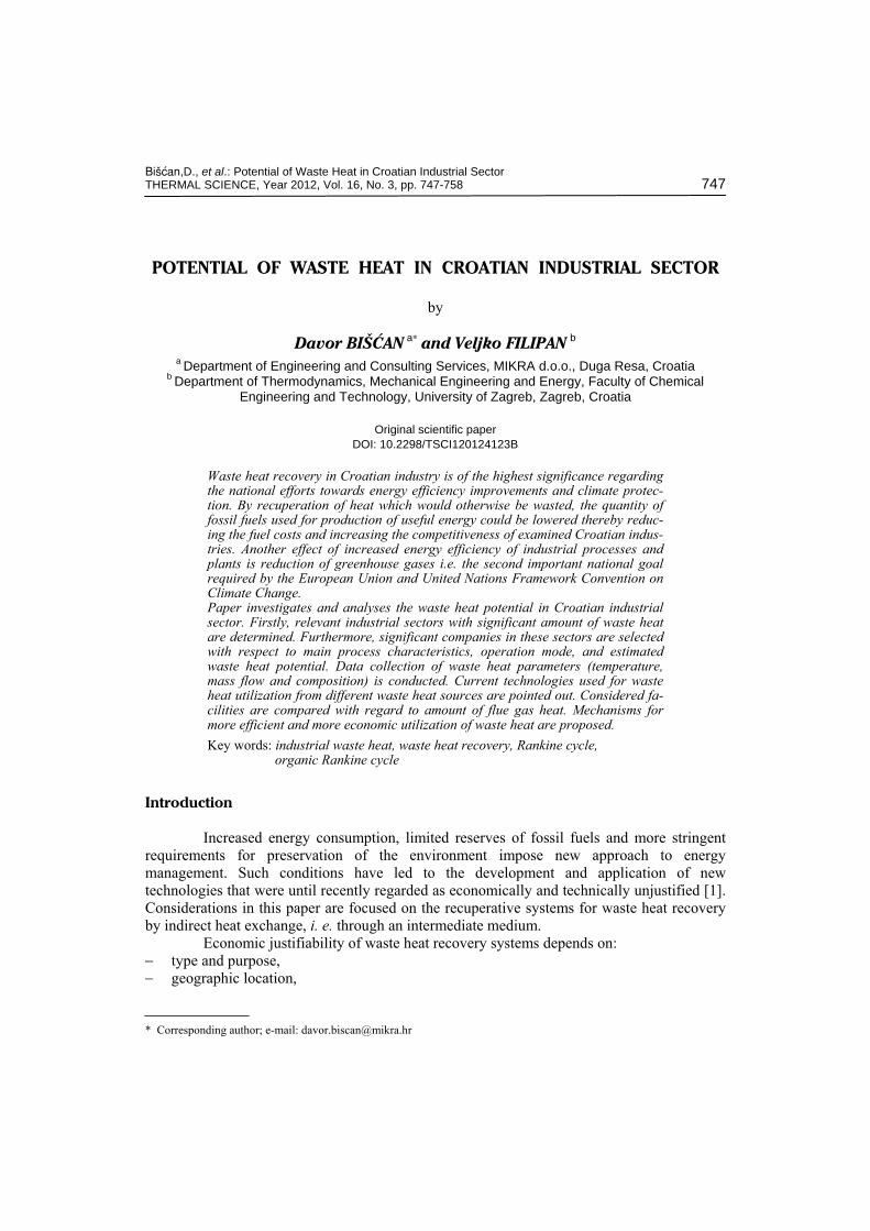
According available data [20] the flue gas temperature varies between 207 and 250 °C, whilst average flue gas mass flow during operation amounts 19660 kg/h. Furthermore the operation is quite intermittent resulting in a limited number of hours in operation annually.
Aluminum production
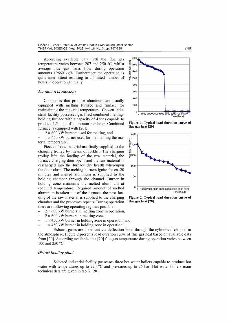
Companies that produce aluminum are usually equipped with melting furnace and furnace for maintaining the material temperature. Chosen indu-strial facility possesses gas fired combined melting-holding furnace with a capacity of 4 tons capable to produce 1.5 tons of aluminum per hour. Combined furnace is equipped with [20]: − 2 × 600 kW burners used for melting, and − 1 × 450 kW burner used for maintaining the ma-terial temperature.
Pieces of raw material are firstly supplied to the charging trolley by means of forklift. The charging trolley lifts the loading of the raw material, the furnace charging door opens and the raw material is discharged into the furnace dry hearth whereupon the door close. The melting burners ignite for ca. 20 minutes and melted aluminum is supplied to the holding chamber through the channel. Burner in holding zone maintains the melted aluminum at required temperature. Required amount of melted aluminum is taken out of the furnace, the next loa-ding of the raw material is supplied to the charging chamber and the processes repeats. During operation there are following operating regimes possible: − 2 × 600 kW burners in melting zone in operation, − 2 × 600 kW burners in melting zone, − 1 × 450 kW burner in holding zone in operation, and − 1 × 450 kW burner in holding zone in operation.
Exhaust gases are taken out via deflection hood through the cylindrical channel to the atmosphere. Figure 2 presents load duration curve of flue gas heat based on available data from [20]. According available data [20] flue gas temperature during operation varies between 100 and 250 °C.
District heating plant
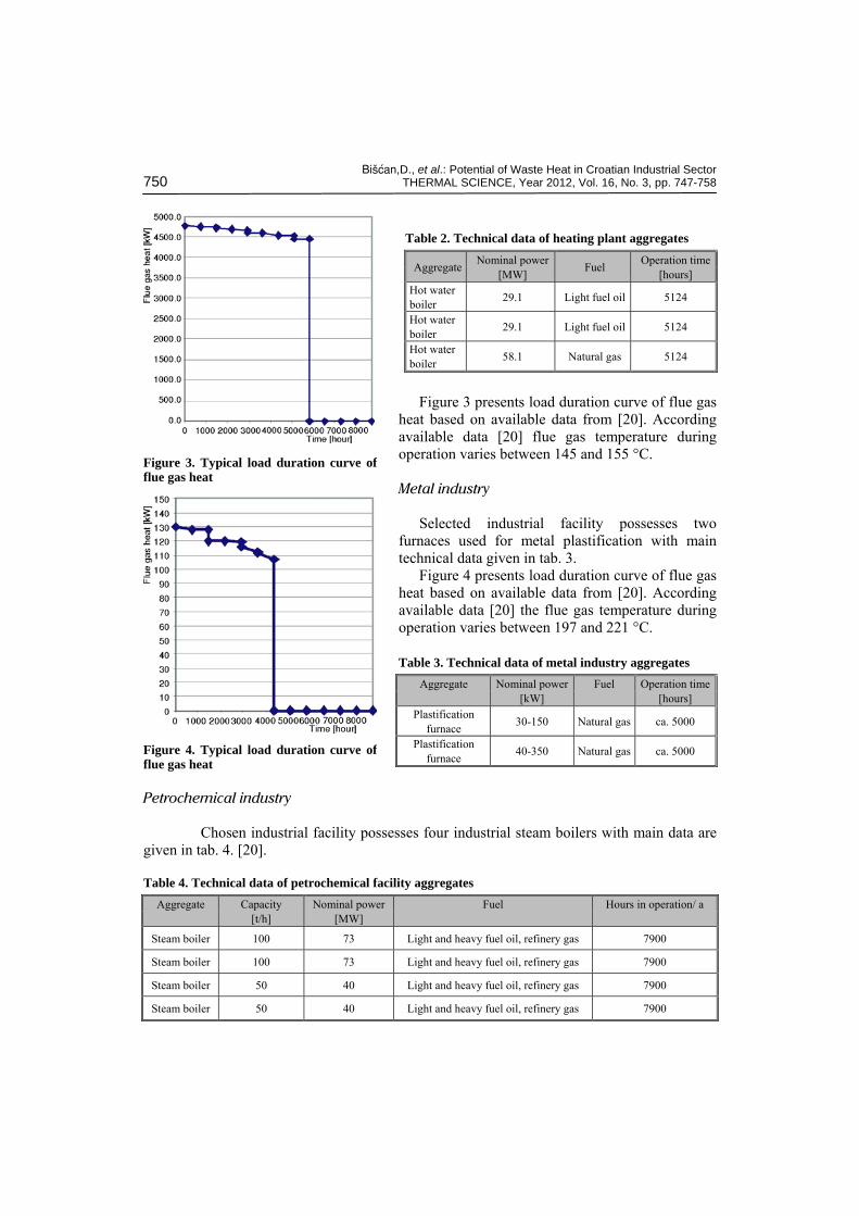
Selected industrial facility possesses three hot water boilers capable to produce hot water with temperatures up to 220 °C and pressures up to 25 bar. Hot water boilers main technical data are given in tab. 2 [20].
Figure 1. Typical load duration curve offlue gas heat [20]
Figure 2. Typical load duration curve offlue gas heat [20]
Bi{}an,D., et al.: Potential of Waste Heat in Croatian Industrial Sector 750 THERMAL SCIENCE, Year 2012, Vol. 16, No. 3, pp. 747-758
Figure 3 presents load duration curve of flue gas
heat based on available data from [20]. According available data [20] flue gas temperature during operation varies between 145 and 155 °C.
Metal industry
Selected industrial facility possesses two furnaces used for metal plastification with main technical data given in tab. 3.
Figure 4 presents load duration curve of flue gas heat based on available data from [20]. According available data [20] the flue gas temperature during operation varies between 197 and 221 °C.
Petrochemical industry
Chosen industrial facility possesses four industrial steam boilers with main data are given in tab. 4. [20].
Table 4. Technical data of petrochemical facility aggregates Aggregate Capacity
[t/h] Nominal power
[MW] Fuel Hours in operation/ a
Steam boiler 100 73 Light and heavy fuel oil, refinery gas 7900
Steam boiler 100 73 Light and heavy fuel oil, refinery gas 7900
Steam boiler 50 40 Light and heavy fuel oil, refinery gas 7900
Steam boiler 50 40 Light and heavy fuel oil, refinery gas 7900
Table 2. Technical data of heating plant aggregates
Aggregate Nominal power [MW] Fuel Operation time
[hours] Hot water boiler 29.1 Light fuel oil 5124
Hot water boiler 29.1 Light fuel oil 5124
Hot water boiler 58.1 Natural gas 5124
Figure 3. Typical load duration curve offlue gas heat
Figure 4. Typical load duration curve offlue gas heat
Table 3. Technical data of metal industry aggregates Aggregate Nominal power
[kW] Fuel Operation time
[hours] Plastification
furnace 30-150 Natural gas ca. 5000
Plastification furnace 40-350 Natural gas ca. 5000
Bi{}an,D., et al.: Potential of Waste Heat in Croatian Industrial Sector THERMAL SCIENCE, Year 2012, Vol. 16, No. 3, pp. 747-758 751
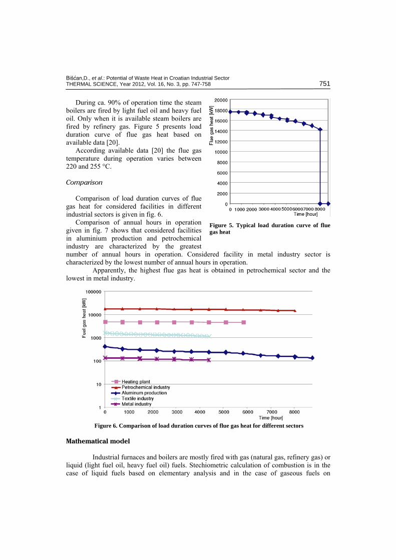
During ca. 90% of operation time the steam boilers are fired by light fuel oil and heavy fuel oil. Only when it is available steam boilers are fired by refinery gas. Figure 5 presents load duration curve of flue gas heat based on available data [20].
According available data [20] the flue gas temperature during operation varies between 220 and 255 °C.
Comparison
Comparison of load duration curves of flue gas heat for considered facilities in different industrial sectors is given in fig. 6.
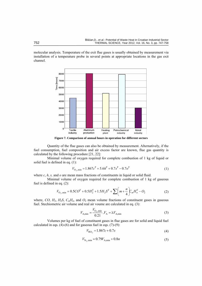
Comparison of annual hours in operation given in fig. 7 shows that considered facilities in aluminium production and petrochemical industry are characterized by the greatest number of annual hours in operation. Considered facility in metal industry sector is characterized by the lowest number of annual hours in operation.
Apparently, the highest flue gas heat is obtained in petrochemical sector and the lowest in metal industry.
Figure 6. Comparison of load duration curves of flue gas heat for different sectors
Mathematical model
Industrial furnaces and boilers are mostly fired with gas (natural gas, refinery gas) or liquid (light fuel oil, heavy fuel oil) fuels. Stechiometric calculation of combustion is in the case of liquid fuels based on elementary analysis and in the case of gaseous fuels on
Figure 5. Typical load duration curve of flue gas heat
Bi{}an,D., et al.: Potential of Waste Heat in Croatian Industrial Sector 752 THERMAL SCIENCE, Year 2012, Vol. 16, No. 3, pp. 747-758
molecular analysis. Temperature of the exit flue gases is usually obtained by measurement via installation of a temperature probe in several points at appropriate locations in the gas exit channel.
Figure 7. Comparison of annual hours in operation for different sectors
Quantity of the flue gases can also be obtained by measurement. Alternatively, if the fuel consumption, fuel composition and air excess factor are known, flue gas quantity is calculated by the following procedure [21, 22]:
Minimal volume of oxygen required for complete combustion of 1 kg of liquid or solid fuel is defined in eq. (1):
FFFFmin,O 7.07.06.5867.1
2oshcV −++= (1)
where c, h, s, and o are mean mass fractions of constituents in liquid or solid fluid. Minimal volume of oxygen required for complete combustion of 1 kg of gaseous
fuel is defined in eq. (2):
2FF
2F2
Fmin,O 4
5.15.05.02
OHCnmSHHCOV nm −⎟⎠⎞
⎜⎝⎛ ++++= ∑ (2)
where, CO, H2, H2S, CmHn, and O2 mean volume fractions of constituent gases in gaseous fuel. Stechiometric air volume and real air voume are calculated in eq. (3):
2O ,min
A,min A A,minλ0 21
VV ,V V
.= = (3)
Volumes per kg of fuel of constituent gases in flue gases are for solid and liquid fuel calculated in eqs. (4)-(6) and for gaseous fuel in eqs. (7)-(9):
scV 7.0867.12RO += (4)
nVV 8.079.0 minA,min,N2+= (5)

Bi{}an,D., et al.: Potential of Waste Heat in Croatian Industrial Sector THERMAL SCIENCE, Year 2012, Vol. 16, No. 3, pp. 747-758 753
whV 24.12.11OH2+= (6)
2
F FRO m nV CO mC H= + ∑ (7)
F2minA,min,N 79.0
2NVV += (8)
2
F FH O 2 2 2
Fm n
nV H H S C H= + + ∑ (9)
Total volume of flue gases per kilogram of fuel is calculated from (10):
( ) minA,OHmin,NROG 1222
VVVVV −+++= λ (10)
Specific enthalpy of flue gases is calculated from (11):
( ) AminA,OHOHNmin,NCOROG 1222222
hVhVhVhVh −+++= λ (11)
For calculation of heat transfer in the downstream process it is necessary to construct h(t) and t(h) polynomials for flue gases. These polynomials are constructed by introduction of specific enthalpies of constituent gases at different temperatures into eq. (11).
In facilities which are equipped with several aggregates, total flue gas enthalpy is calculated from equation (12), where mi denotes mass flow and hi denotes specific enthalpy of each flue gas stream:
G,total i ii
H m h= ∑ (12)
Cost of electricity is calculated from eqs. (13) to (20) [22].
( ) factor Load Hours/year =annually kW per Production × (13)
costs Investment [%]cost Revision =cost Revision × (14)
costs Investment [%]cost M&O = costs M&O × (15)In order to obtain present value of all costs, present value (PV) of each cost is
calculated.
( )ni+11cost Revision =costrevision PV (16)
( )( )n
n
iii+
−+1
11cost M&O =cost M&PVO (17)
cost M&O PV +cost revision PV +cost Investment =costs totalPV (18)
By knowing the present value of costs it is possible to calculate the capital recovery, respectively the annual income which is required for paying off the costs.
Bi{}an,D., et al.: Potential of Waste Heat in Croatian Industrial Sector 754 THERMAL SCIENCE, Year 2012, Vol. 16, No. 3, pp. 747-758
( )
( )turbine
1PV total costs
1 1CR(capitalrecovery)
P
n
ni
i
+×
+ −= (19)
kWper ProductionCR/ =costy Electricit (20)
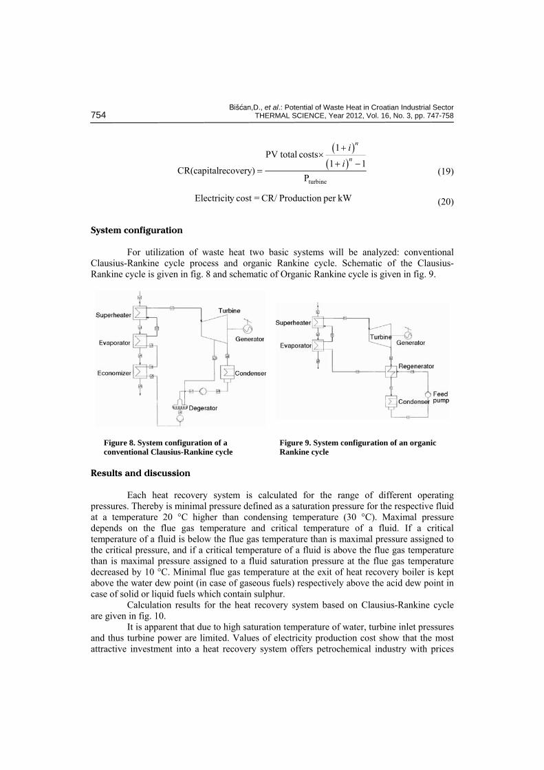
System configuration
For utilization of waste heat two basic systems will be analyzed: conventional Clausius-Rankine cycle process and organic Rankine cycle. Schematic of the Clausius-Rankine cycle is given in fig. 8 and schematic of Organic Rankine cycle is given in fig. 9.
Figure 8. System configuration of a conventional Clausius-Rankine cycle
Figure 9. System configuration of an organic Rankine cycle
Results and discussion
Each heat recovery system is calculated for the range of different operating pressures. Thereby is minimal pressure defined as a saturation pressure for the respective fluid at a temperature 20 °C higher than condensing temperature (30 °C). Maximal pressure depends on the flue gas temperature and critical temperature of a fluid. If a critical temperature of a fluid is below the flue gas temperature than is maximal pressure assigned to the critical pressure, and if a critical temperature of a fluid is above the flue gas temperature than is maximal pressure assigned to a fluid saturation pressure at the flue gas temperature decreased by 10 °C. Minimal flue gas temperature at the exit of heat recovery boiler is kept above the water dew point (in case of gaseous fuels) respectively above the acid dew point in case of solid or liquid fuels which contain sulphur.
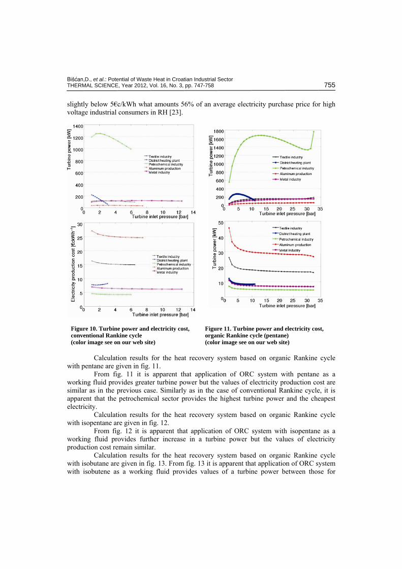
Calculation results for the heat recovery system based on Clausius-Rankine cycle are given in fig. 10.
It is apparent that due to high saturation temperature of water, turbine inlet pressures and thus turbine power are limited. Values of electricity production cost show that the most attractive investment into a heat recovery system offers petrochemical industry with prices
Bi{}an,D., et al.: Potential of Waste Heat in Croatian Industrial Sector THERMAL SCIENCE, Year 2012, Vol. 16, No. 3, pp. 747-758 755
slightly below 5€c/kWh what amounts 56% of an average electricity purchase price for high voltage industrial consumers in RH [23].
Figure 10. Turbine power and electricity cost,conventional Rankine cycle (color image see on our web site)
Figure 11. Turbine power and electricity cost, organic Rankine cycle (pentane) (color image see on our web site)
Calculation results for the heat recovery system based on organic Rankine cycle with pentane are given in fig. 11.
From fig. 11 it is apparent that application of ORC system with pentane as a working fluid provides greater turbine power but the values of electricity production cost are similar as in the previous case. Similarly as in the case of conventional Rankine cycle, it is apparent that the petrochemical sector provides the highest turbine power and the cheapest electricity.
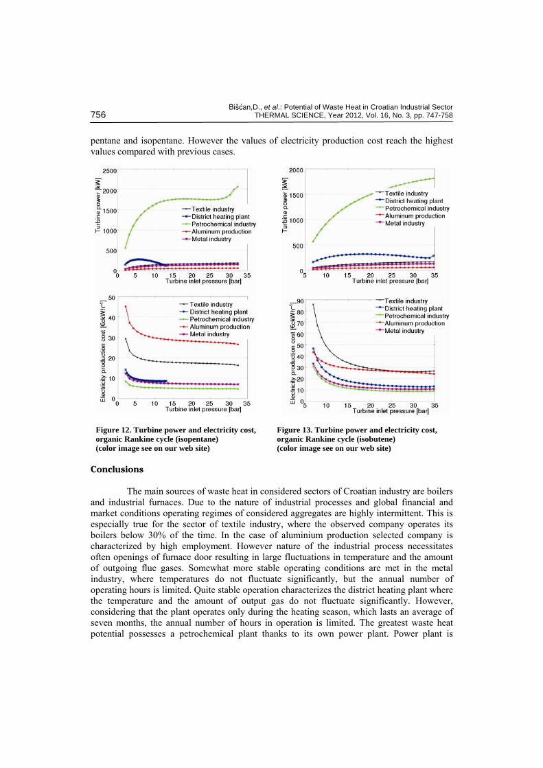
Calculation results for the heat recovery system based on organic Rankine cycle with isopentane are given in fig. 12.
From fig. 12 it is apparent that application of ORC system with isopentane as a working fluid provides further increase in a turbine power but the values of electricity production cost remain similar.
Calculation results for the heat recovery system based on organic Rankine cycle with isobutane are given in fig. 13. From fig. 13 it is apparent that application of ORC system with isobutene as a working fluid provides values of a turbine power between those for
Bi{}an,D., et al.: Potential of Waste Heat in Croatian Industrial Sector 756 THERMAL SCIENCE, Year 2012, Vol. 16, No. 3, pp. 747-758
pentane and isopentane. However the values of electricity production cost reach the highest values compared with previous cases.
Figure 12. Turbine power and electricity cost,organic Rankine cycle (isopentane) (color image see on our web site)
Figure 13. Turbine power and electricity cost, organic Rankine cycle (isobutene) (color image see on our web site)
Conclusions
The main sources of waste heat in considered sectors of Croatian industry are boilers and industrial furnaces. Due to the nature of industrial processes and global financial and market conditions operating regimes of considered aggregates are highly intermittent. This is especially true for the sector of textile industry, where the observed company operates its boilers below 30% of the time. In the case of aluminium production selected company is characterized by high employment. However nature of the industrial process necessitates often openings of furnace door resulting in large fluctuations in temperature and the amount of outgoing flue gases. Somewhat more stable operating conditions are met in the metal industry, where temperatures do not fluctuate significantly, but the annual number of operating hours is limited. Quite stable operation characterizes the district heating plant where the temperature and the amount of output gas do not fluctuate significantly. However, considering that the plant operates only during the heating season, which lasts an average of seven months, the annual number of hours in operation is limited. The greatest waste heat potential possesses a petrochemical plant thanks to its own power plant. Power plant is
Bi{}an,D., et al.: Potential of Waste Heat in Croatian Industrial Sector THERMAL SCIENCE, Year 2012, Vol. 16, No. 3, pp. 747-758 757
equipped with four steam boilers with considerably greater capacity than aggregates in other considered industrial sectors.
Calculation results for application of waste heat recovery system favour the petrochemical industry. In case of application of a conventional Rankine cycle for the petrochemical sector production cost of electricity is slightly below 5 €c/kWh what is ca. 56% of an average value of electricity purchase prices for industrial high voltage consumers [23]. Application of organic Rankine cycle results in a higher turbine power, however, the production cost of electricity is similar to or even slightly higher than the value for the conventional Rankine process. This can be attributed to the high equipment investment costs for the organic Rankine process.
Finally, the following guidelines for more efficient and more cost effective recovery of industrial waste heat can be pointed out: • Monitoring temperature and amount of exit flue gases from a respective aggregate over a
longer period (at least a year), • Determination of a thermal load (pressure, temperature and mass flow) for the respective
industrial facility over a period of one year in order to supply useful heat for the purpose of process heat, space heating, and/or domestic water heating, and
• Determination of a thermal load (pressure, temperature and mass flow) of the nearby in-dustrial and residential entities over a period of one year in order to supply useful heat for the purpose of process heat, space heating, and/or domestic water heating
Acknowledgments
The authors would like to acknowledge the financial support provided by the UNITY THROUGH KNOWLEDGE FUND (UKF) of the Ministry of Science, Education and Sports of the Republic of Croatia and the World Bank, under the Grant Agreement No. 89/11.
Nomenclature
H – enthalpy [kW] h – specific enthalpy [kJkg–1] i – discount rate [%] LF – load factor [ha] m – mass flow [kgs–1] n – economic life time [years] P – plant nominal power [kW, MW] V – volume [m3] λ – air excess factor [–]
Subscripts
A – air
G – gas min – minimal
Superscript
F – fuel
Acronyms
CHP – combined heat and power O&M – operation and maintenance PV – present value
References
[1] Prelec, Z., Energetics in Process Industry (in Croatian), Školska knjiga, Zagreb, 1994 [2] Herr, S., Steam Boilers of Medium Power Capacity (in Croatian), Strojarstvo, 19 (1977), pp. 79-87 [3] Milobar, Ž., Efficiency of Steam Boilers (in Croatian), Strojarstvo, 32 (1990), pp. 227-231 [4] Milobar, Ž., A Slang Sensitive Heat Lost in Steam Boilers (in Croatian), Strojarstvo, 1 (1959), pp.
149-152
Bi{}an,D., et al.: Potential of Waste Heat in Croatian Industrial Sector 758 THERMAL SCIENCE, Year 2012, Vol. 16, No. 3, pp. 747-758
[5] Glažar, V., Prelec, Z., Analysis of Efficiency of Heat Generator System Depending on Type and Load (in Croatian), Strojarstvo, 51 (2009), 2, pp. 143-151
[6] Bilić, F., Methods of Heat Utilization from Waste Air and Gas in Ventilation Plants and Industrial Processes (in Croatian), Strojarstvo, 18 (1976), pp. 49-60
[7] Elčić, Z., The Role of Steam Turbine Units of Small and Intermediate Power Capacities in the Production of Electrical Energy (in Croatian), Strojarstvo 19 (1977), pp. 163-189
[8] Staniša, B., Characteristics of Modern Combined Gas-Steam Turbine Power Plants (in Croatian), Strojarstvo, 36 (1994), pp. 169-183
[9] Prelec, Z., Optimisation of a Steam-generating System in Varying Operating Conditions (in Croatian), Strojarstvo, 30 (1988), pp. 45-51
[10] Bogdan ,Ž., Šerman, N., Cost Optimization of a Cogeneration Plant Operation (in Croatian), Stro-jarstvo, 44 (2002), pp. 17-27
[11] Staniša, B., Prelec, Z., Jakovljević, I., Efficiency Analysis of a Steam Turbine Cogeneration Plant with Capacity 5,7 MWel, Strojarstvo, 30 (2010), 1, pp. 85-96
[12] Bišćan, D., Lončar, D., Optimization of Waste Heat Utilization in Gas Turbine Pipeline Compressor Station (in Croatian), Strojarstvo, 52 (2010) 4, pp. 479-491
[13] Ravi, K. N., Rama, K. K., Sita Rama Raju, A.V., Thermodynamic Analysis of Heat Recovery Steam Generator in Combined Cycle Power Plant, Thermal Science, 11 (2007), 4, pp. 143-156
[14] Sogut, Z., Oktay, Z., Karakoc, H., Mathematical Modeling of Heat Recovery from a Rotary Kiln, Applied Thermal Engineering, 30 (2010), pp. 817–825
[15] Schuster, A. et al., Energetic and Economic Investigation of Organic Rankine Cycle applications, Applied Thermal Engineering, 29 (2009), pp. 1809–1817
[16] Ogulata, T. R., Utilization of Waste-Heat Recovery in Textile Drying, Applied Energy, 79 (2004), pp. 41–49
[17] De Monte, M., Padoano, E., Pozzeto, D., Waste Heat Recovery in a Coffee Roasting Plant, Applied Thermal Engineering, 23 (2003), pp. 1033–1044
[18] ***, Press Release, Innovative steam turbine technology: Wingas and Wingas Transport Expand Transport Capacity, WINGAS GmbH , 2007, http://www.wingas.de/pi-07-08.html?&L=1
[19] Tahani, M., Javan, S., Biglari, M., A Comprehensive Study on Waste Heat Recovery from Internal Combustion Engines Using Organic Rankine Cycle, Thermal Science 2012, OnLine-First, Issue (00:51-51)
[20] ***,Verbal and Written Communication with Relevant Technical Staff in Respective Companies in Considered Industrial Sectors
[21] Kreuh, L., Steam Generators (in Croatian), Školska knjiga, Zagreb, 1978 [22] ***, Digital Tutorial, http://powerlab.fsb.hr/OsnoveEnergetike/udzbenik/ [23] ***, Electricity Purchase Prices, http://www.hep.hr
Paper submitted: January 24, 2012 Paper revised: April 5, 2012 Paper accepted: June 20, 2012