possibilities and challenges of using combined manganese ... · oxygen carriers in chemical-looping...
TRANSCRIPT
THESIS FOR THE DEGREE OF DOCTOR OF PHILOSOPHY
Possibilities and Challenges of Using Combined Manganese Oxides as Oxygen Carriers
MALIN HANNING
Department of Space, Earth and Environment
CHALMERS UNIVERSITY OF TECHNOLOGY
Gothenburg, Sweden 2018

Possibilities and Challenges of Using Combined Manganese Oxides as Oxygen Carriers MALIN HANNING ISBN 978-91-7597-724-9 © MALIN HANNING, 2018. Doktorsavhandlingar vid Chalmers tekniska högskola Ny serie nr 4405 ISSN 0346-718X Department of Space, Earth and Environment Chalmers University of Technology SE-412 96 Gothenburg Sweden Telephone + 46 (0)31-772 1000 Printed by Chalmers Reproservice Gothenburg, Sweden 2018

i
Possibilities and Challenges of Using Combined Manganese Oxides as Oxygen Carriers
MALIN HANNING Division of Energy Technology
Department of Space, Earth and Environment Chalmers University of Technology
Abstract One alternative proposed to reduce greenhouse gas emissions is carbon capture and storage, where the carbon dioxide emitted from large point sources is captured, compressed and stored in underground geological formations. Many of the largest point sources of carbon dioxide are power plants and industries fuelled by fossil fuels or biomass. There are several technologies for adapting the combustion process to capture carbon dioxide and chemical-looping combustion is one such option. It has the advantage of keeping the fuel and the combustion air apart, thus avoiding energy consuming and costly separation of carbon dioxide and nitrogen. This is achieved by transferring oxygen from the air to the fuel by a cyclic oxidation and reduction of a solid metal oxide.
The oxygen-carrier material needs to meet several requirements in order to achieve an efficient combustion process. Manganese oxides have promising properties as oxygen-carrier material and these can be further improved by combining manganese with for example iron, silica and calcium. Chemical-looping combustion is mainly developed as a technology for fluidised-bed combustion, with the oxygen carrier present as bed material in the form of small particles. To perform well in a circulating fluidised bed, the oxygen carrier needs to be mechanically stable as well as have good reactivity with the fuel.
The work presented in this thesis examines the performance of manganese combined oxides as oxygen carriers in chemical-looping combustion units and in a conventional circulating fluidised bed. The operation has been carried out in two reactor systems with gaseous fuels and in a large-scale biomass boiler, in which the properties of the materials have been evaluated. It has been shown that full conversion of the fuel can be achieved in chemical-looping combustion with calcium manganites as oxygen carrier. Furthermore, combined oxides of iron-manganese-silica and manganese-silica have been examined. High fuel conversion was achieved with both combined oxide systems, but the mechanical stability of these materials was poor. It was found that the mechanical stability of combined oxides of manganese-silica could be improved by adding titania to the material. Interactions between a manganese ore and biomass ash were studied and it was found that ash components accumulated in the particles during operation in the biomass boiler. The reactivity of the ore decreased during operation which could be an effect of deactivation by the ash elements.
Keywords: carbon capture, chemical-looping combustion, oxygen carriers, combined oxides, manganese oxides, manganese ores

ii
iii
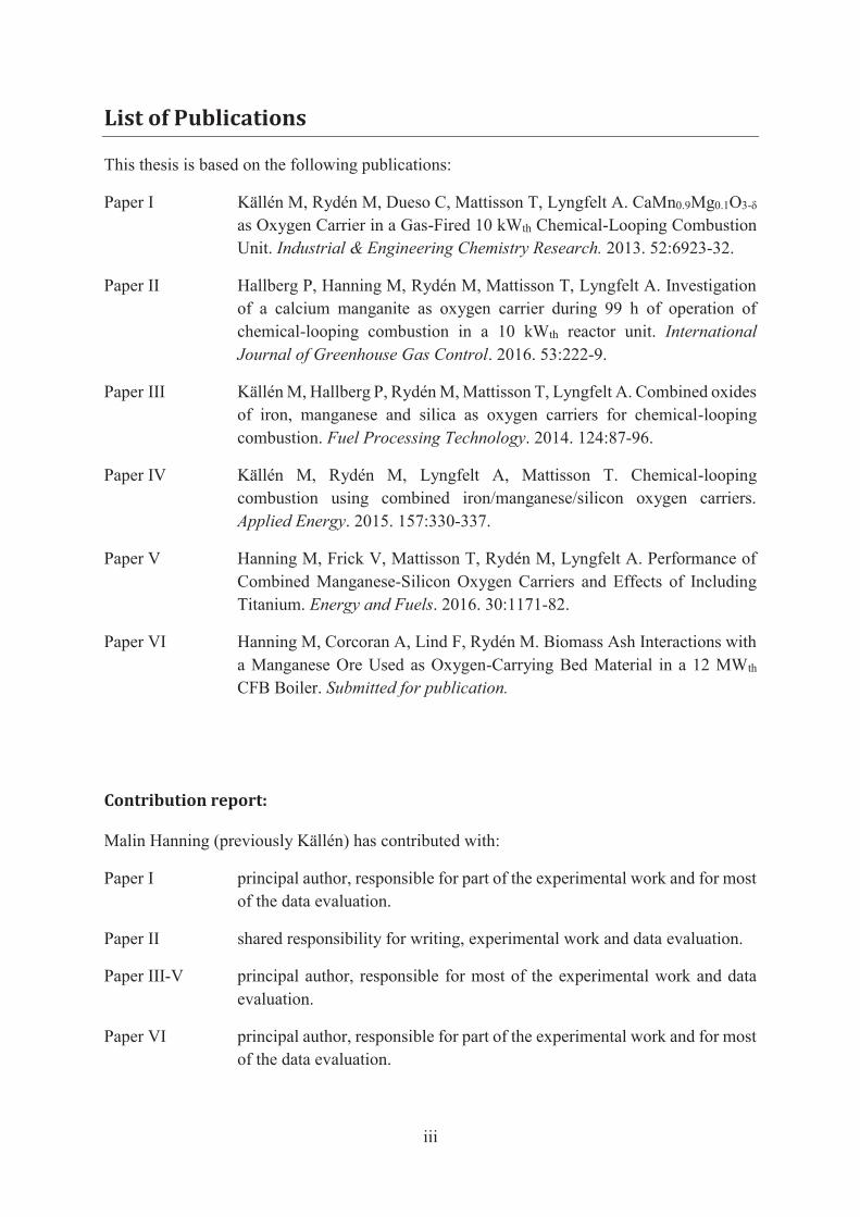
List of Publications
This thesis is based on the following publications:
Paper I Källén M, Rydén M, Dueso C, Mattisson T, Lyngfelt A. CaMn0.9Mg0.1O3-δ as Oxygen Carrier in a Gas-Fired 10 kWth Chemical-Looping Combustion Unit. Industrial & Engineering Chemistry Research. 2013. 52:6923-32.
Paper II Hallberg P, Hanning M, Rydén M, Mattisson T, Lyngfelt A. Investigation of a calcium manganite as oxygen carrier during 99 h of operation of chemical-looping combustion in a 10 kWth reactor unit. International Journal of Greenhouse Gas Control. 2016. 53:222-9.
Paper III Källén M, Hallberg P, Rydén M, Mattisson T, Lyngfelt A. Combined oxides of iron, manganese and silica as oxygen carriers for chemical-looping combustion. Fuel Processing Technology. 2014. 124:87-96.
Paper IV Källén M, Rydén M, Lyngfelt A, Mattisson T. Chemical-looping combustion using combined iron/manganese/silicon oxygen carriers. Applied Energy. 2015. 157:330-337.
Paper V Hanning M, Frick V, Mattisson T, Rydén M, Lyngfelt A. Performance of Combined Manganese-Silicon Oxygen Carriers and Effects of Including Titanium. Energy and Fuels. 2016. 30:1171-82.
Paper VI Hanning M, Corcoran A, Lind F, Rydén M. Biomass Ash Interactions with a Manganese Ore Used as Oxygen-Carrying Bed Material in a 12 MWth CFB Boiler. Submitted for publication.
Contribution report:
Malin Hanning (previously Källén) has contributed with:
Paper I principal author, responsible for part of the experimental work and for most of the data evaluation.
Paper II shared responsibility for writing, experimental work and data evaluation.
Paper III-V principal author, responsible for most of the experimental work and data evaluation.
Paper VI principal author, responsible for part of the experimental work and for most of the data evaluation.

iv
Related publications not included in this thesis:
Jerndal E, Leion H, Axelsson L, Ekvall T, Hedberg M, Johansson K, Källén M, Svensson, R, Mattisson T, Lyngfelt A. Using low-cost iron-based materials as oxygen carriers for chemical looping combustion. Oil and Gas Science and Technology. 2011. 66:235-248.
Rydén M, Källén M, Jing D, Hedayati A, Mattisson T, Lyngfelt A. (Fe1-xMnx)TiyO3 based oxygen carriers for chemical-looping combustion and chemical-looping with oxygen uncoupling. Energy Procedia. 2013. 51:85-98.
Hallberg P, Källén M, Jing D, Snijkers F, van Noyen J, Rydén M, Lyngfelt A. Experimental investigation of CaMnO3-δ based oxygen carriers used in continuous chemical-looping combustion. International Journal of Chemical Engineering. 2014. 412517.
Rydén M, Jing D, Källén M, Leion H, Lyngfelt A, Mattisson T. CuO-based oxygen-carrier particles for chemical-looping with oxygen uncoupling – Experiments in batch reactor and in continuous operation. Industrial and Engineering Chemistry Research. 2014. 53:6255-6267.
Linderholm C, Schmitz M, Knutsson P, Källén M, Lyngfelt A. Use of low-volatile solid fuels in a 100 kW chemical-looping combustor. Energy and Fuels. 2014. 28:5942-5952.
Rydén M, Hanning M, Corcoran A, Lind F. Oxygen carrier aided combustion (OCAC) of wood chips in a semi-commercial circulating fluidized bed boiler using manganese ore as bed material. Applied Science. 2016. 6:1-19.
Linderholm C, Schmitz M, Biermann M, Hanning M, Lyngfelt A. Chemical-looping combustion of solid fuel in a 100 kW unit using sintered manganese ore as oxygen carrier. International Journal of Greenhouse Gas Control. 2017. 65:170-181.
v
Acknowledgements
I want to thank my supervisors Magnus Rydén and Anders Lyngfelt for always taking the time to discuss and answer my questions. Magnus, thank you for your relaxed attitude which always makes me calm down when I am stressed over things and for sharing your vast knowledge of many fascinating subfields. Anders, thank you for your enthusiasm which always makes me motivated to improve my work.
I want to thank Tobias Mattisson for acting as my supervisor in practice, although not being it in theory. I would also like to take the opportunity to thank Henrik Leion for introducing me to the world of chemical-looping combustion; it is because of you that I ended up doing a PhD.
Louise, I want to thank you for always being there throughout all our years at Chalmers. We have become engineers, mothers and soon PhDs together, it has been a privilege to share it all with you.
A large part of this work has been carried out in the CLC-lab, and I am really grateful to Patrick, Peter, Matthias, Calle, Max and Jesper for all the fun we’ve had there. The days spent in the power central were mostly a pure pleasure thanks to Angelica, Johannes, Jessica and Fredrik. I also want to thank Ulf and Rustan for all practical help and for cheering me up when I was frustrated over practical things.
I want to thank all fantastic chemical-loopers I’ve met during these years: Dazheng, Golnar, Sebastian, Volkmar, Martin, Pavleta, Mehdi, Georg, Pontus, Fredrik, Ivan and Dongmei. I am also very grateful to all colleagues at Energy Technology for creating a great working atmosphere and for all fun discussions at lunch and fika-time. I also want to add a great thanks to the A-team for always bringing order in everything from parental leave issues to celebrations.
My greatest thankfulness goes to my family and my friends. Thank you for always being there and supporting me. I especially want to thank Sofia and Emelie for all fun trips and other projects we’ve done during these years that have helped me to keep my mind off work.
I want to say special thanks to my parents who taught me to be curious and that I should always do my best. Mathilda, you have changed everything, for the better. Finally, Hasse, thank you for all love and support. I am so grateful for sharing life with you.

vi
vii
Table of Contents
1. Introduction ........................................................................................................................ 1
1.1. Chemical-Looping Combustion................................................................................... 2
1.2. Oxygen Carriers ........................................................................................................... 3
1.2.1. Manganese Oxygen Carriers ................................................................................ 7
1.2.2. Ash Interactions ................................................................................................... 8
1.3. Oxygen-Carrier Aided Combustion ............................................................................. 8
1.4. Aim and Scope of Thesis ............................................................................................. 9
2. Experimental .................................................................................................................... 11
2.1. Oxygen Carriers ......................................................................................................... 11
2.2. Experimental Units .................................................................................................... 13
2.2.1. 300 Wth Chemical-Looping Reactor .................................................................. 13
2.2.2. 10 kWth Chemical-Looping Reactor .................................................................. 15
2.2.3. 12 MWth Biomass Boiler ................................................................................... 17
2.3. Analysis Methods ...................................................................................................... 18
2.4. Data Analysis ............................................................................................................. 20
3. Results and Discussion .................................................................................................... 23
3.1. Is it possible to reach complete fuel conversion? (Paper I and II) ............................. 23
3.2. What can be achieved by changing the chemical composition? (Paper III, IV and V) .................................................................................................. 26
3.3. What affects the particle lifetime? (Paper V) ............................................................ 33
3.4. Does biomass ash affect the oxygen carrier? (Paper VI) ........................................... 35
3.5. Outlook ...................................................................................................................... 39
4. Conclusions ...................................................................................................................... 41
Nomenclature ........................................................................................................................... 43
References ................................................................................................................................ 45

viii
1
1. Introduction
The continuing increase of greenhouse gases in the atmosphere will cause climate change associated with an increased global temperature. [1] The changes in the climate will inevitably harm ecosystems as well as living conditions for humans in many parts of the world. [2] There is evidence that ecosystems already are affected by the increased global temperature. [3] The largest increase in greenhouse gas emissions to date was observed in the decade 2000-2010 with an average increase of 2.2%/year. A quarter of the total emissions of greenhouse gases originates from the production of electricity and heat, a sector which is mainly fuelled by fossil fuels. [4]
Renewable energy sources, like solar and wind power, are often viewed as the solution to the energy supply problem. However, even though the implementation of these technologies is developing very fast [5], it will take a long time for them to substitute fossil fuels completely. Carbon capture and storage (CCS) has been proposed as a bridging technology between the current energy production and a future renewable energy system. The CCS concept consists of the capture of carbon dioxide from point sources such as power plants, followed by compression, transportation and finally deposition at a storage site. [6] Bioenergy with carbon capture and storage (BECCS) could even make it possible to achieve negative greenhouse gas emissions, which is regarded as necessary if the climate targets are to be reached. [7, 8] The theoretical potential of BECCS is substantial, even though there are several practical obstacles such as the scale of the forestry and the accessible CCS infrastructure required. [9] However, for other strategies for negative emissions, such as afforestation and increased soil carbon storage, the main drawbacks are that the degree of carbon dioxide removal is depending on desired ecosystem services for e.g. food production and that the sequestration time may not be sufficient. [10] BECCS differs from these land-use and management changes in these aspects and offers a long-term and large-scale approach for achieving net negative emissions.
All CCS technologies are associated with a cost related to capture, transport and storage of the carbon dioxide. If CCS and/or BECCS are implemented in full scale, a large share of the added cost will come from the capturing process of carbon dioxide. Several technologies for carbon dioxide capture have been developed and they can be classified in three categories: pre-combustion, post-combustion and oxy-fuel combustion. In pre-combustion capture, gaseous fuels can be converted to carbon monoxide and hydrogen in a water-gas shift reactor. The carbon monoxide is then reacted with steam to form carbon dioxide and more hydrogen. A gas separation unit is necessary to separate the carbon dioxide from the hydrogen, which can be used as a carbon free fuel. Solid fuel would need to be gasified for pre-combustion capture, which would require an air separation unit to produce the pure oxygen needed. In post-combustion capture the carbon dioxide is separated from the flue gases after combustion in a gas separation unit. In oxy-fuel combustion the fuel is burnt in oxygen and recycled flue gases. Thus, an air separation unit is thus needed. [6] All these technologies would require gas-gas separation which thermodynamically requires work input and is thus costly and very energy intensive. Another capture technology proposed, named chemical-looping combustion (CLC), avoids this separation and may therefore capture carbon dioxide at a much lower cost. [11]

2
1.1. Chemical-Looping Combustion The concept of chemical-looping combustion is based on the ability of certain metal oxides to change oxidation state depending on surrounding chemical environment and temperature. In this way, combustion can be carried out in two separate reactor vessels without gas mixing between the two. The metal oxide is oxidised by air in one vessel, the air reactor (AR), and reduced by the fuel in the other, the fuel reactor (FR). The fuel is thus oxidised by the oxygen carried to the fuel reactor by the metal oxide. A simplified combustion scheme is illustrated in Figure 1.
Figure 1. The combustion scheme of chemical-looping combustion.
The heat of combustion will be identical to normal combustion in air. This can be shown by adding up the two reaction steps shown below, where reaction 1 occurs in the air reactor and reaction 2 in the fuel reactor: + → (1) (2 + ) + → (2 + ) + + (2)
As is seen in the reactions above, the metal oxide is often not reduced fully to the metallic state, although this is a possibility and depends on the metal oxide used. The combustion route will differ depending on the type of fuel being burnt. In combustion of gaseous fuels, the fuel can react directly with the oxygen carrier in a gas-solid reaction. In combustion of a solid fuel, the volatiles will first be released in gaseous form and then react directly with the oxygen carrier. The remaining char needs to be gasified to react with the oxygen carrier in a gas-solid reaction.
Char gasification with steam is rather slow compared to the other reactions in the combustion scheme and would therefore be the rate limiting factor for the conversion of the char. This could be problematic, as a long fuel residence time in the fuel reactor may be needed for complete burnout.
3
The choice of oxygen carrier offers a way to get around the gasification step. Some metal oxides are capable of releasing oxygen in gaseous form at temperatures relevant for fuel combustion according to: → + (3)
Some, or all, char can then react directly with the gaseous oxygen released and will not need to be gasified. This combustion scheme is referred to as chemical-looping with oxygen uncoupling (CLOU). [12] Chemical-looping with oxygen uncoupling can also be advantageous in combustion of gaseous fuels as it would enable a gas-gas reaction between oxygen and fuel, instead of a gas-solid reaction which requires a good contact. This implies that CLOU can facilitate complete combustion even though the mixing between oxygen carrier and fuel is not sufficient.
A common way to realise chemical-looping combustion is by using two interconnected fluidised bed reactors. The oxygen carrier then has the form of small particles of a suitable size range. By using this method, knowledge and experience of combustion in circulating fluidised bed (CFB) boilers can be used. The air reactor is a circulating fluidised bed with high gas velocities, which is needed to transport the particles from the bed to the fuel reactor. The fuel reactor can either be a bubbling bed with lower gas velocities or a circulating fluidised bed with an internal circulation loop. The latter is usually regarded to be more advantageous for solid fuels, due to mixing issues and possibilities for scale-up. Most chemical-looping pilot units in operation today uses interconnected fluidised beds as combustion method. [13]
Chemical-looping combustion was first introduced as a technology to produce carbon dioxide from coal in a patent application in 1954. [14] Later, the idea of using the process to capture carbon dioxide from combustion of fossil fuels was formed. [15] The proof of concept came in 2004, when Lyngfelt and Thunman [16] constructed and operated a 10 kWth chemical-looping combustor for more than 100 h. The development has progressed very fast since the first studies. Today more than 700 oxygen-carrier materials have been examined worldwide and the total continuous operation now amounts to more than 9 000 h in chemical-looping units ranging from 300 Wth to 3 MWth. [17-23]
1.2. Oxygen Carriers The development of oxygen carrier materials is an important part of the progress of chemical-looping combustion. There are many properties which are desired for oxygen carriers. Suitable chemical properties of the metal oxide is usually the first criterion to be fulfilled if an oxygen carrier should be regarded as promising. The material should be oxidised and reduced at sufficient rate at relevant temperatures and not break down due to chemical stress. The mass fraction of oxygen that the oxygen carrier can transfer per cycle, i.e. the oxygen transfer capacity, is another important parameter. The material should not be deactivated by ash or other fuel components such as sulphur.

4
If the oxygen carrier will be used in chemical-looping with oxygen uncoupling, the rate of oxygen release will be a central parameter. For this to be achieved, it is necessary that the equilibrium partial pressure of oxygen is high enough for creating a sufficient driving force for the oxygen transfer.
If the combustion is carried out in fluidised beds, the mechanical integrity is another decisive property as the gas velocities in such reactors are high and the material will follow the gas flow through cyclones. When chemical-looping is scaled up to commercial scale, large quantities of the oxygen carrier material will need to be handled. Therefore, it is preferable if the material is rather cheap and neither toxic nor environmentally harmful. If a solid fuel is to be used, it is also questionable how high separation efficiency of ash and oxygen carrier that can be achieved. These issues have more recently directed the research to natural materials such as ores. [24]
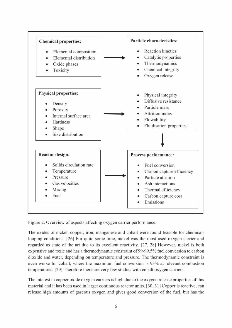
As described above, there are many desired properties for oxygen carriers. Some of these depend on the chemical composition of the oxygen carrier material and some depend on the physical structure of the particles. The actual process performance, however, will not only depend on the oxygen carrier, but on the process design as well. These different aspects of oxygen carrier design and performance are summarised in Figure 2. The connection between oxygen carrier design and process performance is not straight forward and will require great effort to be optimised.
The main focus has historically been on the chemical properties of the material, but there are a large number of physical properties that will decide the performance as well. The physical properties of the material will not only affect the physical performance of the particles, but the chemical properties as well. For example, very dense particles with a low internal surface area will in most cases give slower reactions with surrounding gases due to the lower internal diffusion. The lower reactivity for denser particles has been observed in studies where the manufacturing parameters have been varied. [25]
There will most probably be a trade-off between all the desired oxygen carrier performance criteria. There are several different proposed designs of chemical-looping reactors and the requirement on the oxygen carrier will differ between these. Depending on residence times, gas velocities and temperature range, varying oxygen carrier properties will be most important. The possibility to recycle the oxygen carrier will be determined by the fuel depending on ash interactions and the possibility to separate oxygen carrier from the ashes.
5
Figure 2. Overview of aspects affecting oxygen carrier performance.
The oxides of nickel, copper, iron, manganese and cobalt were found feasible for chemical-looping conditions. [26] For quite some time, nickel was the most used oxygen carrier and regarded as state of the art due to its excellent reactivity. [27, 28] However, nickel is both expensive and toxic and has a thermodynamic constraint of 99-99.5% fuel conversion to carbon dioxide and water, depending on temperature and pressure. The thermodynamic constraint is even worse for cobalt, where the maximum fuel conversion is 93% at relevant combustion temperatures. [29] Therefore there are very few studies with cobalt oxygen carriers.
The interest in copper oxide oxygen carriers is high due to the oxygen release properties of this material and it has been used in larger continuous reactor units. [30, 31] Copper is reactive, can release high amounts of gaseous oxygen and gives good conversion of the fuel, but has the
Chemical properties:
Elemental composition Elemental distribution Oxide phases Toxicity
Physical properties:
Density Porosity Internal surface area Hardness Shape Size distribution
Particle characteristics:
Reaction kinetics Catalytic properties Thermodynamics Chemical integrity Oxygen release
Physical integrity Diffusive resistance Particle mass Attrition index Flowability Fluidisation properties
Reactor design:
Solids circulation rate Temperature Pressure Gas velocities Mixing Fuel
Process performance:
Fuel conversion Carbon capture efficiency Particle attrition Ash interactions Thermal efficiency Carbon capture cost Emissions

6
disadvantage of being rather expensive. The mechanical stability of copper based oxygen-carrier materials is also uncertain. [32-34]
Iron oxides have frequently been studied as oxygen carriers for chemical-looping combustion. The reactivity is usually acceptable and the mechanical stability is regarded as good. Iron ores often have a high concentration of iron and can therefore be utilised as oxygen carrier directly. The most examined natural material, ilmenite, is an iron and titanium ore. A recent review article has summarised the research on iron oxygen carriers. [35]
Nickel and copper oxides have been regarded as the most advantageous choices for oxygen carriers due to their good reactivity. It may, however, be that the disadvantages mentioned above will be more decisive and that a non-toxic and cheaper material will be needed. Manganese oxides satisfy the requirements of not being toxic and being significantly cheaper than nickel and copper. They furthermore have oxygen release properties at combustion temperatures.
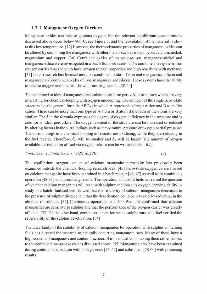
The equilibrium oxygen partial pressure is shown as a function of temperature for manganese, cobalt and copper oxide in Figure 3. The equilibrium partial pressure of oxygen will not only affect the oxygen release in the fuel reactor, but also the driving force for the oxidation in the air reactor. The equilibrium partial pressure needs to be low enough for oxidation to occur at a reasonable oxygen concentration. A high partial pressure of oxygen out from the air reactor means operating with a high air-to-fuel ratio which gives a high heat loss associated with the flue gases. Normally employed air-to-fuel ratios correspond to an outlet concentration of oxygen at around 5 vol.%. Consequently, the equilibrium partial pressure of oxygen needs to be below this level at the air reactor temperature for oxidation to occur throughout the entire reactor volume.
↔ + ↔ + ↔ +
Figure 3. Equilibrium oxygen partial pressure of manganese, cobalt and copper oxide and the corresponding phase transition reactions (figure courtesy of Dr. M. Rydén).
7
1.2.1. Manganese Oxygen Carriers
Manganese oxides can release gaseous oxygen, but the relevant equilibrium concentrations discussed above occur below 800°C, see Figure 3, and the reoxidation of the material is slow at this low temperature. [12] However, the thermodynamic properties of manganese oxides can be altered by combining the manganese with other metals such as iron, silicon, calcium, nickel, magnesium and copper. [36] Combined oxides of manganese-iron, manganese-nickel and manganese-silica were investigated in a batch fluidised reactor. The combined manganese-iron oxygen carrier was shown to have oxygen release properties and high reactivity with methane. [37] Later research has focused more on combined oxides of iron and manganese, silicon and manganese and combined oxides of iron, manganese and silicon. These systems have the ability to release oxygen and have all shown promising results. [38-44]
The combined oxides of manganese and calcium can form perovskite structures which are very interesting for chemical-looping with oxygen uncoupling. The unit cell of the single perovskite structure has the general formula ABO3-δ in which A represents a larger cation and B a smaller cation. There can be more than one type of A atom or B atom if the radii of the atoms are very similar. The δ in the formula expresses the degree of oxygen deficiency in the structure and is zero for an ideal perovskite. The oxygen content of the structure can be increased or reduced by altering factors in the surroundings such as temperature, pressure or oxygen partial pressure. The surroundings in a chemical-looping air reactor are oxidising, while they are reducing in the fuel reactor. Therefore, δar will be smaller and δfr will be larger. The amount of oxygen available for oxidation of fuel via oxygen release can be written as (δfr - δar): CaMnO3-δar ↔ CaMnO3-δfr + ½(δfr-δar) O2 (4)
The equilibrium oxygen content of calcium manganite perovskite has previously been examined outside the chemical-looping research area. [45] Perovskite oxygen carriers based on calcium manganite have been examined in a batch reactor [46, 47] as well as in continuous operation [48-51] with promising results. The operation with solid fuels has raised the question of whether calcium manganites will react with sulphur and loose its oxygen carrying ability. A study in a batch fluidised bed showed that the reactivity of calcium manganites decreased in the presence of sulphur dioxide, but that the deactivation could be reversed by reduction in the absence of sulphur. [52] Continuous operation in a 500 Wth unit confirmed that calcium manganites are sensitive to sulphur and that the performance of the oxygen carrier was greatly affected. [53] On the other hand, continuous operation with a sulphurous solid fuel verified the reversibility of the sulphur deactivation. [54]
The uncertainty of the suitability of calcium manganites for operation with sulphur containing fuels has directed the research to naturally occurring manganese ores. Many of these have a high content of manganese and contain fractions of iron and silicon, making them rather similar to the combined manganese oxides discussed above. [55] Manganese ores have been examined during continuous operation with both gaseous [56, 57] and solid fuels [58-60] with promising results.

8
1.2.2. Ash Interactions
Biomass ashes are known to be highly reactive and if CLC is to be used for BECCS, the interactions between the oxygen carriers and the ash components need to be examined. The characterisation of the ash components is important for the operation of fluidised bed boilers, since ash can cause agglomeration of the bed material and thus establishes the maximum possible operation temperature. The agglomeration is usually caused by the reaction of alkali with silica forming alkali silicates, which have low melting temperatures and tend to form agglomerates. Potassium is most often the main alkali source in biomass ashes. Potassium may also react with chlorine, forming gaseous potassium chloride. This compound can cause problems such as corrosion and fouling in the convection path of the boiler. The formation of alkali chloride compounds also promotes the reaction of alkali with silicates since the mobility of alkali increases when present in gaseous form. [61, 62] The alkali balance in the boiler, and thus its effects on the operation, is affected by the interaction between these species and the bed material. Using bed materials other than the commonly used silica sand may reduce the tendency for agglomeration formation. [63] Consequently, it could increase the problems related to deposition of alkali on down-stream heat-transfer surfaces as more alkali will leave the bed in gaseous form.
When an oxygen carrier is used as bed material to transport oxygen within the bed or between multiple beds, ash interaction could cause additional effects apart from bed agglomeration. Ash components attaching to the surface of the particles may either decrease or increase the oxidation and reduction rates of the oxygen carrier. The reaction rate can be reduced if gas diffusion is hindered by an ash layer on the surface of particles. It is also possible that attaching ash components could have a catalysing effect on the reaction or even have oxygen carrier properties. Ash components reacting with the oxygen carrier and altering the composition could either increase or decrease the oxygen transport capacity depending on the compounds formed.
There are few publications on interactions between ash and oxygen carriers, and most concern coal ash components. [64-68] However, there are some studies on interactions between biomass ash and iron based oxygen carriers. [69, 70]
1.3. Oxygen-Carrier Aided Combustion The research on oxygen carriers has gained additional attention during the last years due to their ability to improve conventional combustion in fluidised bed boilers. Several advantages can be obtained by replacing the inert bed material with an oxygen carrier. The technology is referred to as Oxygen-Carrier Aided Combustion (OCAC). [71]
Fuel mixing is a key aspect affecting the combustion performance in fluidised-bed boilers. Insufficient mixing between fuel and oxygen during combustion results in emissions of carbon monoxide and unburnt hydrocarbons in the flue gases. To minimise these emissions, commercial combustion plants are operated with an excess of air added to the furnace. This implies that the physical size of the combustion plants must be oversized to meet a specified fuel load. The air excess also increases the heat loss associated with the flue gas and thus decreases the overall efficiency of the plant. Common measures to avoid poor mixing are
9
optimisation of the air staging and of the fuel feeding. These issues could be addressed by using an oxygen carrier as bed material.
When the inert bed material commonly used in fluidised bed combustion is replaced with an oxygen carrier, the oxidation and reduction of the bed material (reaction 1 and 2) will create additional reaction routes for combustion. The fuel can react directly with the oxygen provided in the air, with the oxygen released by the oxygen carrier or with the oxygen carrier itself. The bed material will be oxidised in parts of the combustion chamber where oxygen is available in excess, while it will be reduced in parts where fuel is available in excess. Thus, the availability of a given amount of oxygen can be more evenly distributed throughout the combustion chamber. The active bed material will also work as an oxygen buffer preventing spikes in emissions during uneven fuel feeding and would facilitate conversion of relatively stable fuel components such as methane by direct solid-gas reactions inside the bed, where ignition otherwise may be hampered by thermal inertia. [72]
A first study concerning OCAC conducted in the 12 MWth circulating fluidised bed research boiler at Chalmers University showed very promising results. [71] By substituting 40 wt.% of the inert sand bed with the oxygen carrying mineral ilmenite (consisting of iron and titanium oxides), an 80% decrease of carbon monoxide in the flue gases could be achieved. A manganese ore was later operated in the same boiler showing that issues related to the alkali balance of the boiler must be taken into account in the choice of bed material. [72] Recently, ilmenite has been successfully operated for more than 12,000 h as active bed material in full industrial scale. [73] Ilmenite used for OCAC has been shown to absorb potassium, which binds to titanium in the core of the particles. [70]
1.4. Aim and Scope of Thesis Although there had been some previous efforts on finding suitable combined manganese oxides for utilisation in chemical-looping, most work had been conducted in small laboratory units with a very limited number of red-ox cycles. This work is the first major effort to investigate combined manganese oxides in continuous operation. The objective of this research was to evaluate the performance of combined manganese oxides as oxygen carriers in continuous chemical-looping operation.
The study was carried out in research pilots of various scale and thus in more realistic conditions than previous studies. The oxygen release, reactivity with fuel and mechanical stability were the key performance indicators assessed. The long-term aim is to find viable oxygen carrier materials for large-scale operation. The oxygen carrier materials studied had been selected based on evaluation in batch reactors and were regarded as promising.
The papers included in the thesis focus on different aspects on oxygen carrier performance. In paper I and II, calcium manganite oxygen carriers have been operated for several days in a 10 kWth chemical-looping reactor. The focus in these papers were on reaching very high fuel conversion and establishing a mass balance to estimate particle lifetime. In paper III - V, various combined manganese oxides were operated in a 300 Wth chemical-looping reactor. The focus was on examining how the oxygen carrier properties were affected by varying chemical

10
composition of the combined oxides. In paper VI, a manganese ore was operated in a 12 MWth biomass CFB boiler and the focus was on studying how the biomass ash interacted with the ore as well as on examining how the particles were affected by long-term operation in a large-scale boiler.

11
2. Experimental
The papers included in this thesis are based on experimental work carried out in three different scales: units designed for thermal powers of 300 Wth, 10 kWth and 12 MWth. The experimental procedures, the units used and the oxygen carriers examined are described in this chapter.
2.1. Oxygen Carriers The oxygen-carrier materials used were all manufactured particles, except the manganese ore examined in paper VI. The synthesised oxygen-carrier materials were produced by spray drying by VITO in Belgium. Spray drying is a commercial particle production method which is used for multi-ton production of a wide variety of materials. The oxygen carrier particles were produced as follows. The raw materials, most often metal oxides, were mixed with water and some organic additives and then sprayed in fine droplets into a hot chamber whereby the liquid evaporated and the raw materials formed small particles. The material was then sintered at a high temperature with a dwell time of four hours at the top temperature. During this time, the raw materials reacted to form the combined oxide structure and the material hardened. Usually a higher sintering temperature and a longer sintering time will give particles with higher mechanical stability, but with lower reactivity. The oxygen-carrier materials, the sintering temperature and particle properties are summarised in Table 1.
Table 1. Oxygen carrier materials, sintering temperatures and particle properties.
Name Sintering temperature
(°C)
Raw materials (wt.%)
Mean size (μm)
Bulk density (kg/m3)
Attrition index[74] (wt.%/h)
Paper I CaMn0.9Mg0.1O3-δ 1300 46.8% Mn3O4 50.5% Ca(OH)2
2.7% MgO
137 1920 0.6
Paper II CaMn0.775Ti0.125Mg0.1O3- 1350 40.1% Mn3O4 50.3% Ca(OH)2
2.7% MgO 6.8% TiO2
149 1300 8.9
Paper III
Fe0.66Mn1.33SiO3 1100 47.3% Mn3O4 27.9% SiO2 24.8% Fe2O3
153 1026 32.3
FeMnSiO3 1100 35.3% Mn3O4 27.8% SiO2 36.9% Fe2O3
147 1240 1.2
Paper IV
F22M44S33 1200 47.3% Mn3O4 27.9% SiO2 24.8% Fe2O3
153 1030 19.3
F22M55S22 1200 57.7% Mn3O4 18.1% SiO2 24.2% Fe2O3
145 1000 16.3
F22M66S11 1200 67.5% Mn3O4 8.9% SiO2
23.6% Fe2O3
139 1470 4.6
Paper V
MnSi 1150 75% Mn3O4 25% SiO2
136 1000 17.4
MnSiTi 1140 66.7% Mn3O4 22.2% SiO2 11.0% TiO2
126 1688 0.5

12
The bulk density reported was measured as the mass poured into a known volume. The attrition index reported was calculated from measurements using a customised jet cup; see the article by Rydén et. al. for a description of the jet cup and testing methodology. [74] A high attrition index indicates a high production of fines, i.e. poor physical integrity. The results from these tests with fresh material are used here as a comparison to the experimental attrition behaviour in the hot unit. The oxygen carrier names reported in the table are identical with those used in the papers. These materials have all been examined in a laboratory batch reactor previously and were selected for continuous operation in larger reactor units based on their good characteristics.
The development of oxygen carriers at Chalmers University of Technology has most often followed the seven steps shown in Figure 4. Paper I and II concern results from step 7, as these materials had previously been examined in the 300 Wth chemical-looping reactor with promising results. [49] Paper III-V concern results from step 5, and those studies involved the first continuous operation of these materials.
Figure 4. General scheme for the development of oxygen carriers at Chalmers University of Technology.
As the scale of the operation is increased, the conditions are more realistic and can give a better estimation of the performance of the oxygen carrier material. The gas velocities are much higher in the larger unit and the operation can be carried out during longer time periods, thus exposing the material to many more cycles between oxidising and reducing conditions. However, the larger scale requires much larger batches of oxygen carrier, as can be seen in Figure 4, and the experimental work becomes much more time consuming.
13
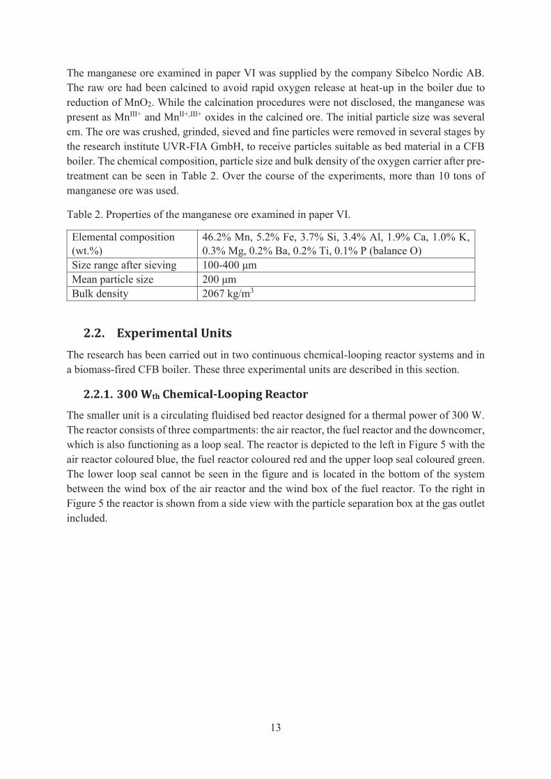
The manganese ore examined in paper VI was supplied by the company Sibelco Nordic AB. The raw ore had been calcined to avoid rapid oxygen release at heat-up in the boiler due to reduction of MnO2. While the calcination procedures were not disclosed, the manganese was present as MnIII+ and MnII+,III+ oxides in the calcined ore. The initial particle size was several cm. The ore was crushed, grinded, sieved and fine particles were removed in several stages by the research institute UVR-FIA GmbH, to receive particles suitable as bed material in a CFB boiler. The chemical composition, particle size and bulk density of the oxygen carrier after pre-treatment can be seen in Table 2. Over the course of the experiments, more than 10 tons of manganese ore was used.
Table 2. Properties of the manganese ore examined in paper VI.
Elemental composition (wt.%)
46.2% Mn, 5.2% Fe, 3.7% Si, 3.4% Al, 1.9% Ca, 1.0% K, 0.3% Mg, 0.2% Ba, 0.2% Ti, 0.1% P (balance O)
Size range after sieving 100-400 μm Mean particle size 200 μm Bulk density 2067 kg/m3
2.2. Experimental Units The research has been carried out in two continuous chemical-looping reactor systems and in a biomass-fired CFB boiler. These three experimental units are described in this section.
2.2.1. 300 Wth Chemical-Looping Reactor
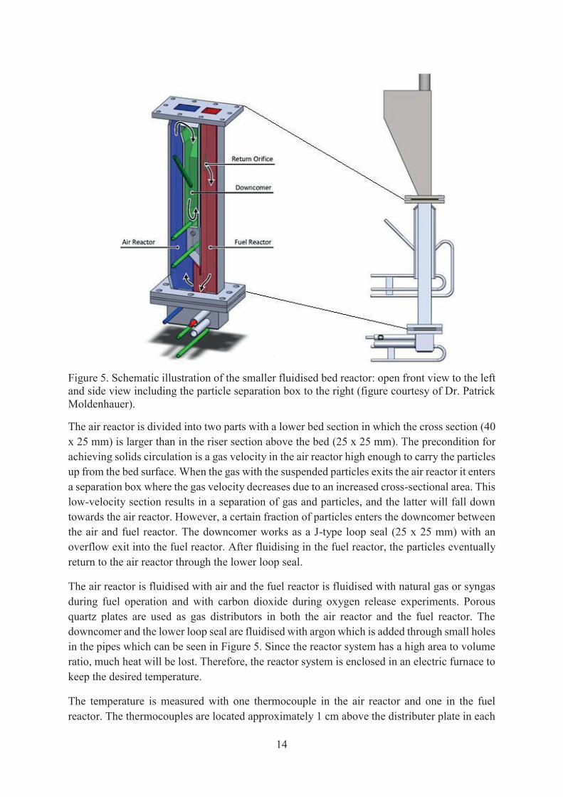
The smaller unit is a circulating fluidised bed reactor designed for a thermal power of 300 W. The reactor consists of three compartments: the air reactor, the fuel reactor and the downcomer, which is also functioning as a loop seal. The reactor is depicted to the left in Figure 5 with the air reactor coloured blue, the fuel reactor coloured red and the upper loop seal coloured green. The lower loop seal cannot be seen in the figure and is located in the bottom of the system between the wind box of the air reactor and the wind box of the fuel reactor. To the right in Figure 5 the reactor is shown from a side view with the particle separation box at the gas outlet included.
14
Figure 5. Schematic illustration of the smaller fluidised bed reactor: open front view to the left and side view including the particle separation box to the right (figure courtesy of Dr. Patrick Moldenhauer).
The air reactor is divided into two parts with a lower bed section in which the cross section (40 x 25 mm) is larger than in the riser section above the bed (25 x 25 mm). The precondition for achieving solids circulation is a gas velocity in the air reactor high enough to carry the particles up from the bed surface. When the gas with the suspended particles exits the air reactor it enters a separation box where the gas velocity decreases due to an increased cross-sectional area. This low-velocity section results in a separation of gas and particles, and the latter will fall down towards the air reactor. However, a certain fraction of particles enters the downcomer between the air and fuel reactor. The downcomer works as a J-type loop seal (25 x 25 mm) with an overflow exit into the fuel reactor. After fluidising in the fuel reactor, the particles eventually return to the air reactor through the lower loop seal.
The air reactor is fluidised with air and the fuel reactor is fluidised with natural gas or syngas during fuel operation and with carbon dioxide during oxygen release experiments. Porous quartz plates are used as gas distributors in both the air reactor and the fuel reactor. The downcomer and the lower loop seal are fluidised with argon which is added through small holes in the pipes which can be seen in Figure 5. Since the reactor system has a high area to volume ratio, much heat will be lost. Therefore, the reactor system is enclosed in an electric furnace to keep the desired temperature.
The temperature is measured with one thermocouple in the air reactor and one in the fuel reactor. The thermocouples are located approximately 1 cm above the distributer plate in each
15
reactor. The pressure drops in the reactor system are measured by pressure transducers in the air reactor, fuel reactor and in the downcomer. The pressure drops are measured to be able to assess the fluidisation behaviour and the solids inventory in the different parts of the reactor system.
The outlet of the fuel reactor is connected to a water seal with a 1-2 cm column of water giving a slightly higher pressure in the fuel reactor than in the air reactor. This is done to minimise the risk for air leakage into the fuel reactor from the air reactor. A part of each outlet stream is led through a particle filter and a gas conditioning unit before entering the gas analysers.
2.2.2. 10 kWth Chemical-Looping Reactor
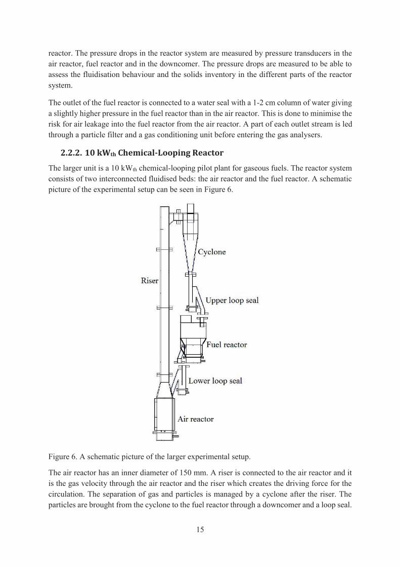
The larger unit is a 10 kWth chemical-looping pilot plant for gaseous fuels. The reactor system consists of two interconnected fluidised beds: the air reactor and the fuel reactor. A schematic picture of the experimental setup can be seen in Figure 6.
Figure 6. A schematic picture of the larger experimental setup.
The air reactor has an inner diameter of 150 mm. A riser is connected to the air reactor and it is the gas velocity through the air reactor and the riser which creates the driving force for the circulation. The separation of gas and particles is managed by a cyclone after the riser. The particles are brought from the cyclone to the fuel reactor through a downcomer and a loop seal.
16
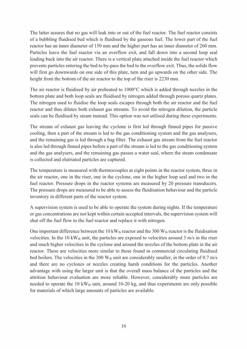
The latter assures that no gas will leak into or out of the fuel reactor. The fuel reactor consists of a bubbling fluidised bed which is fluidised by the gaseous fuel. The lower part of the fuel reactor has an inner diameter of 150 mm and the higher part has an inner diameter of 260 mm. Particles leave the fuel reactor via an overflow exit, and fall down into a second loop seal leading back into the air reactor. There is a vertical plate attached inside the fuel reactor which prevents particles entering the bed to by-pass the bed to the overflow exit. Thus, the solids flow will first go downwards on one side of this plate, turn and go upwards on the other side. The height from the bottom of the air reactor to the top of the riser is 2230 mm.
The air reactor is fluidised by air preheated to 1000°C which is added through nozzles in the bottom plate and both loop seals are fluidised by nitrogen added through porous quartz plates. The nitrogen used to fluidise the loop seals escapes through both the air reactor and the fuel reactor and thus dilutes both exhaust gas streams. To avoid the nitrogen dilution, the particle seals can be fluidised by steam instead. This option was not utilised during these experiments.
The stream of exhaust gas leaving the cyclone is first led through finned pipes for passive cooling, then a part of the stream is led to the gas conditioning system and the gas analysers, and the remaining gas is led through a bag filter. The exhaust gas stream from the fuel reactor is also led through finned pipes before a part of the stream is led to the gas conditioning system and the gas analysers, and the remaining gas passes a water seal, where the steam condensate is collected and elutriated particles are captured.
The temperature is measured with thermocouples at eight points in the reactor system, three in the air reactor, one in the riser, one in the cyclone, one in the higher loop seal and two in the fuel reactor. Pressure drops in the reactor systems are measured by 20 pressure transducers. The pressure drops are measured to be able to assess the fluidisation behaviour and the particle inventory in different parts of the reactor system.
A supervision system is used to be able to operate the system during nights. If the temperature or gas concentrations are not kept within certain accepted intervals, the supervision system will shut off the fuel flow to the fuel reactor and replace it with nitrogen.
One important difference between the 10 kWth reactor and the 300 Wth reactor is the fluidisation velocities. In the 10 kWth unit, the particles are exposed to velocities around 3 m/s in the riser and much higher velocities in the cyclone and around the nozzles of the bottom plate in the air reactor. These are velocities more similar to those found in commercial circulating fluidised bed boilers. The velocities in the 300 Wth unit are considerably smaller, in the order of 0.7 m/s and there are no cyclones or nozzles creating harsh conditions for the particles. Another advantage with using the larger unit is that the overall mass balance of the particles and the attrition behaviour evaluation are more reliable. However, considerably more particles are needed to operate the 10 kWth unit, around 10-20 kg, and thus experiments are only possible for materials of which large amounts of particles are available.

17
2.2.3. 12 MWth Biomass Boiler
The operation with manganese ore as bed material was carried out in a CFB boiler located at Chalmers University of Technology. The boiler was initially designed for using coal as fuel with a maximum load of 12 MWth. Presently, the boiler is fuelled with wood chips and the maximum load is around 8 MWth, but is most often operated at the slightly lower load of 5-6 MWth. The boiler is used to produce hot water for district heating during the cold season. The boiler is integrated with a gasifier in form of a secondary, bubbling bed. It can be included in the particle circulation by fluidising the loop seals connected to it. The gasifier is fuelled with wood pellets. Fuel samples were collected each day of operation and a mix from the entire week was sent to SP Technical Research Institute of Sweden for total and ash analysis; one wood chip sample and one wood pellet sample. A schematic picture of the boiler system is shown in Figure 7.
Figure 7. Schematic picture of the boiler system. Particle extraction points are marked with red dots.
It should be noted that this operation was carried out as conventional combustion and not chemical-looping combustion. The interconnected gasifier was in operation during several days under the experimental campaign, exposing the bed material to more reducing conditions than in the boiler. In this way the gasifier acted similar to a fuel reactor and the boiler acted similar to an air reactor, even though combustion occurred there as well. This campaign provided a unique opportunity to examine manganese oxygen-carrier particles which had been
18
subjected to long-term operation in a circulating fluidised bed at high temperature and with combustion reactions. So even though no complete chemical-looping operation was conducted, the conditions could be regarded as highly relevant for evaluation of oxygen carrier performance.
Bed samples were extracted during operation using a cooled collection probe at three locations: in the bottom bed in the boiler and in the loops seals before (seal 1) and after (seal 2) the gasifier. These collection points are marked with red dots in Figure 7. Bottom bed samples were taken each day and samples from the loop seals were taken each day the gasifier was in operation. The boiler was operated with only manganese ore as bed material for a little more than a week without regeneration of the bed. Four of the bed samples from this period were chosen for analysis to study how the operation affected the particles.
Fly ash samples were also taken each day, both from the secondary cyclone and from the textile filter, see Figure 7. The boiler was operated at around 850-870°C, except for a short period when the temperature was decreased to 800°C. The air-to-fuel ratio was varied between 1.07-1.17 during the experiments to study the oxygen-carrying ability of the bed material. The operation of the boiler and the combustion performance achieved are further described by Rydén et. al. [72] The operational performance of the gasifier has been reported by Berdugo Vilches et. al. [75]
2.3. Analysis Methods The oxygen carriers examined in paper III-V were operated in the 300 Wth unit during fluidisation in inert atmosphere as well as during operation with fuel, both syngas (50% CO and 50% H2) and natural gas or pure methane. The reactivity with the syngas components, hydrogen and carbon monoxide, is important to evaluate, as these are the main products from steam gasification of char and are also present as significant fractions in the volatile part of solid fuels. The oxygen release behaviour of the material can be studied during fluidisation in inert atmosphere. Temperature, air flow and fuel flow have been varied during the experiments to evaluate their effect on the performance of the oxygen carriers. All experiments have been conducted during continuous operation for several hours.
The calcium manganites examined in paper I and II were operated in the 10 kWth unit. In this case, the oxygen release was studied during heat up when the fuel reactor was fluidised with nitrogen. The fuel operation was then conducted with natural gas as fuel. The fuel and air flows were varied to change the power load and the circulation rate. In this unit, it was also possible to follow the attrition rate of the oxygen carrier originating from the high gas velocities in the reactor unit. This was done by weighing the bag filters each day of operation and sieving a sample of the particles found.
The 300 Wth and the 10 kWth reactor units were connected to identical gas conditioning systems and gas analysers. The gas analysers measured the concentration of carbon dioxide, carbon monoxide, methane and oxygen from the fuel reactor and the concentrations of oxygen and carbon dioxide from the air reactor. Methane, carbon monoxide and carbon dioxide were
19
measured with IR-sensors while oxygen was measured with a paramagnetic sensor. Gas concentrations, temperatures and pressure drops were logged every ten seconds.
The manganese ore operated in the CFB boiler was thoroughly analysed after operation to study the effect of the biomass ash on the oxygen carrier. Each extracted bed sample consisted of 300-900 g of particles and a sample divider was used to obtain representative amounts for each analysis. The particle size distribution was determined by sieving a sample of approximately 50 g. The attrition resistance was measured for particles in the size range of 125-180 μm in a customised jet-cup rig. [74] The bed and fly ash samples were sent to ALS Scandinavia for elemental composition analysis. The physical shape of the particles was examined using scanning electron microscopy (SEM), which was coupled to an energy dispersive X-ray spectroscopy (EDX) used to study the distribution of the elements within the particles. The samples were mounted in epoxy resin and polished to get a through-cut of the particles for the SEM/EDX analysis.
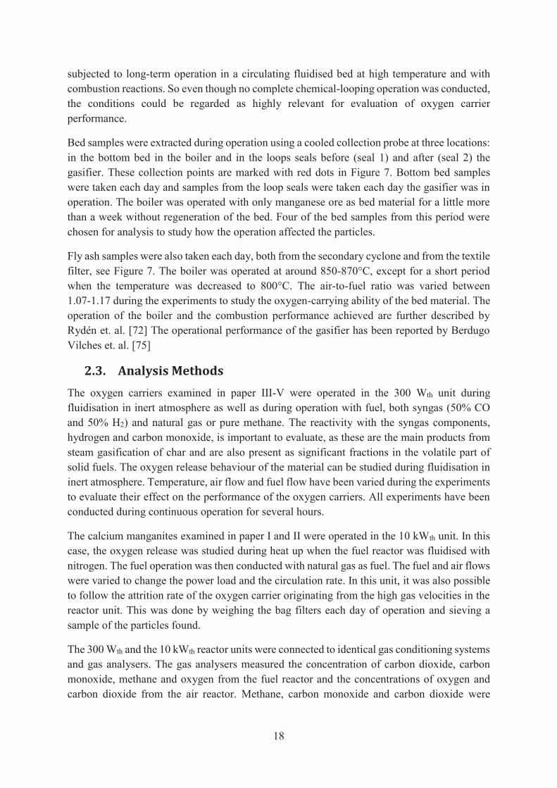
The reactivity of the oxygen carriers in paper V and VI were examined in a batch fluidised bed reactor made of quartz glass. The experimental setup has been thoroughly described in paper V and is shown in Figure 8.
Figure 8. Experimental setup for batch reactivity experiments. TI indicates the two temperature measurements and PDI indicates the measurement of the pressure drop over the bed.
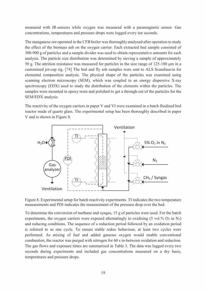
To determine the conversion of methane and syngas, 15 g of particles were used. For the batch experiments, the oxygen carriers were exposed alternatingly to oxidising (5 vol.% O2 in N2) and reducing conditions. The sequence of a reduction period followed by an oxidation period is referred to as one cycle. To ensure stable redox behaviour, at least two cycles were performed. As mixing of fuel and added gaseous oxygen would enable conventional combustion, the reactor was purged with nitrogen for 60 s in-between oxidation and reduction. The gas flows and exposure times are summarised in Table 3. The data was logged every two seconds during experiments and included gas concentrations measured on a dry basis, temperatures and pressure drops.
5% O2 in N2
N2
CH4 / Syngas
Ventilation
TI
TI
PDIGas
analyzer
Ventilation
H2O
20
Table 3. Exposure times and gas flows used in batch fluidised-bed experiments.
Exposure time [s] Gas flow [ml/min] N2 360 600 5 vol.% O2 in N2 until oxidation is complete 900 Syngas 80 450 CH4 20 450 Charcoal + N2 until no more oxygen is released 600
2.4. Data Analysis From the gas concentration measurements, the CO2 yield was calculated to evaluate the combustion performance. The CO2 yield is defined as the amount of carbon dioxide formed divided by the total amount of carbon species in the outlet flow according to: = (5)
During the experiments in the smaller reactor unit, the outlet from the fuel reactor was also analysed with a gas chromatograph which measures hydrogen and nitrogen, as well as the previously mentioned gases. The hydrogen measurements give additional information of the fuel conversion and are especially interesting for the conversion of syngas. The nitrogen measurements are used to measure the amount of air leakage from the air reactor to the fuel reactor.
The circulation rate in the 10 kWth unit has been assessed to evaluate the operating conditions in the system. The following expression, previously used by Linderholm et. al. [76] for this unit, has been used to calculate the net solid flux: = ( − ) = − ( − ) (6)
The net solids flux calculated by this expression overestimates the actual circulation, but it is still a useful measure for comparing particle circulations. The net solid flux multiplied with the cross-sectional area of the riser is referred to as circulation index (CI) and is expressed in kg/min.
The gas concentration measurements from the batch reactor had to be evaluated differently as the operation is divided into separate cycles. The mass-based oxygen carrier conversion enables a comparison of oxygen carriers containing different amounts of oxygen. It is calculated as the ratio of the current mass of the oxygen carrier and the mass of the oxygen carrier in its fully oxidised form according to equation (7). = (7)

21
The oxygen carrier conversion as a function of time is calculated according to equation (8) for syngas conversion and according to equation (9) for methane conversion.
= − 2 + − (8)
= − 4 + 3 − (9)
The reported CO2 yields are averages calculated for the periods when 1 > > 0.99, also in the cases when continued to decrease below 0.99. As the hydrogen concentration in the outlet stream was not measured, it was calculated with the assumption that the water shift reaction was at equilibrium.

23
3. Results and Discussion
In this section, some of the results from the included papers are presented. The results are chosen to highlight the main findings in relation to the objectives presented in section 1.4. For detailed information the reader is referred to the attached papers.
3.1. Is it possible to reach complete fuel conversion? (Paper I and II)
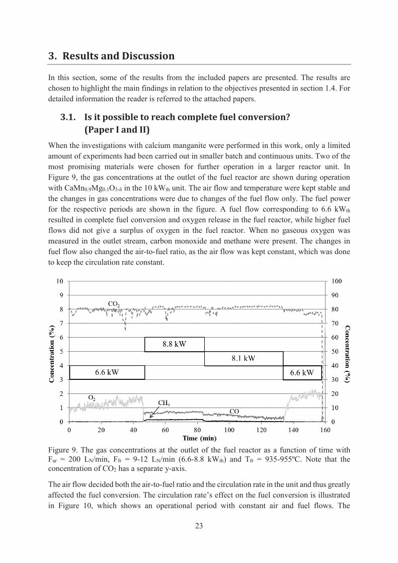
When the investigations with calcium manganite were performed in this work, only a limited amount of experiments had been carried out in smaller batch and continuous units. Two of the most promising materials were chosen for further operation in a larger reactor unit. In Figure 9, the gas concentrations at the outlet of the fuel reactor are shown during operation with CaMn0.9Mg0.1O3-δ in the 10 kWth unit. The air flow and temperature were kept stable and the changes in gas concentrations were due to changes of the fuel flow only. The fuel power for the respective periods are shown in the figure. A fuel flow corresponding to 6.6 kWth resulted in complete fuel conversion and oxygen release in the fuel reactor, while higher fuel flows did not give a surplus of oxygen in the fuel reactor. When no gaseous oxygen was measured in the outlet stream, carbon monoxide and methane were present. The changes in fuel flow also changed the air-to-fuel ratio, as the air flow was kept constant, which was done to keep the circulation rate constant.
Figure 9. The gas concentrations at the outlet of the fuel reactor as a function of time with Far = 200 LN/min, Ffr = 9-12 LN/min (6.6-8.8 kWth) and Tfr = 935-955ºC. Note that the concentration of CO2 has a separate y-axis.
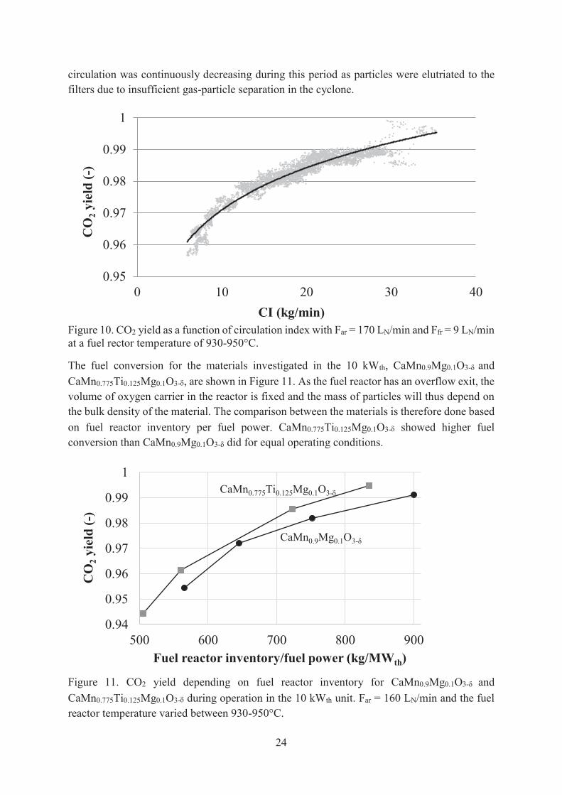
The air flow decided both the air-to-fuel ratio and the circulation rate in the unit and thus greatly affected the fuel conversion. The circulation rate’s effect on the fuel conversion is illustrated in Figure 10, which shows an operational period with constant air and fuel flows. The
24
circulation was continuously decreasing during this period as particles were elutriated to the filters due to insufficient gas-particle separation in the cyclone.
Figure 10. CO2 yield as a function of circulation index with Far = 170 LN/min and Ffr = 9 LN/min at a fuel rector temperature of 930-950°C.
The fuel conversion for the materials investigated in the 10 kWth, CaMn0.9Mg0.1O3-δ and CaMn0.775Ti0.125Mg0.1O3- , are shown in Figure 11. As the fuel reactor has an overflow exit, the volume of oxygen carrier in the reactor is fixed and the mass of particles will thus depend on the bulk density of the material. The comparison between the materials is therefore done based on fuel reactor inventory per fuel power. CaMn0.775Ti0.125Mg0.1O3- showed higher fuel conversion than CaMn0.9Mg0.1O3-δ did for equal operating conditions.
Figure 11. CO2 yield depending on fuel reactor inventory for CaMn0.9Mg0.1O3-δ and CaMn0.775Ti0.125Mg0.1O3- during operation in the 10 kWth unit. Far = 160 LN/min and the fuel reactor temperature varied between 930-950°C.
0.95
0.96
0.97
0.98
0.99
1
0 10 20 30 40
CO
2yi
eld
(-)
CI (kg/min)
0.94
0.95
0.96
0.97
0.98
0.99
1
500 600 700 800 900
CO
2yi
eld
(-)
Fuel reactor inventory/fuel power (kg/MWth)
CaMn0.775Ti0.125Mg0.1O3-
CaMn0.9Mg0.1O3-δ

25
The ability to convert the fuel is a main criterion for the evaluation of oxygen carrier materials. As shown in Figure 9, it was possible to achieve full conversion of the fuel during the operation with CaMn0.9Mg0.1O3-δ in the 10 kWth unit. The operation with CaMn0.775Ti0.125Mg0.1O3- in the same reactor unit also showed a very high conversion of the fuel, as shown in Figure 11. The high capability of calcium manganites to convert the fuel can partly be explained by their oxygen release behaviour. Calcium manganites have a perovskite structure and can thus release oxygen without changing their crystal structure, as explained in section 1.2.1. The perovskite structure has shown to be advantageous in chemical-looping combustion and high concentrations of released oxygen have been reported, see for example Fig. 3 in paper II. The importance of a high rate of circulation, i.e. constantly supplying highly oxidised oxygen-carrier particles, was shown in Figure 10.
Another precondition for a high fuel conversion, as in all kinds of combustion, is a good mixing of oxygen and fuel. In this case, the operation was carried out with gaseous fuel fluidising the fuel reactor and the mixing between the fuel and the released oxygen could be hindered by formation of large bubbles. In Figure 9, it can be seen that either oxygen or combustible gases were measured in the fuel reactor outlet during the entire period. Excess oxygen would not desirable if the exhaust carbon dioxide should be compressed for storage since oxygen can cause corrosion problems. The presence of oxygen would thus mean that a separation unit would be needed downstream, which would be highly desirable to avoid. However, periods with very low levels of both combustibles and oxygen were achieved. An example is the short time period after 140 min seen in Figure 12, where the concentrations of methane and oxygen are zero and the concentration of carbon monoxide is below 0.5 vol.%.
Figure 12. The gas concentrations at the outlet of the fuel reactor with Far = 200 LN/min and Ffr = 9 LN/min (6.6 kW) during a peak in circulation index.
0
0.005
0.01
0.015
0.02
0.025
0.03
135 140 145 150 155 160
Con
cent
ratio
n (-
)
Time (min)
O2
CO
CH4
26
The bag filter in the outlet from the air reactor was emptied regularly and the particles were sieved to establish the amount of fines formed. The fines formation stabilised at a very low level after only a few days of operation for both calcium manganites. The measured rate of attrition corresponded to a particle lifetime of 12 000 h for CaMn0.9Mg0.1O3-δ and 9 000 h for CaMn0.775Ti0.125Mg0.1O3- .
In general, calcium manganites have proven to work very well in operation with gaseous fuels and complete fuel conversion has been achieved. However, it is uncertain how this material would perform in long-term operation with sulphur containing fuels. Calcium manganites may be deactivated by the sulphur present in most solid fuels and some gaseous fuels. [52] The formation and decomposition of solid sulphur compounds in conditions varying between oxidising and reducing are difficult to predict. Operational experience with solid fuels indicates that sulphur compounds are formed but the results are not conclusive. [54] This would need to be investigated more before calcium manganites are further developed for sulphur containing fuels.
3.2. What can be achieved by changing the chemical composition? (Paper III, IV and V)
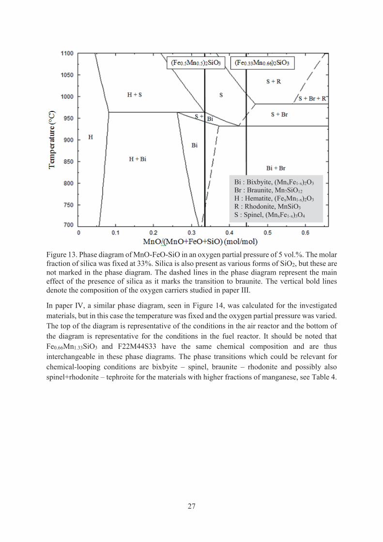
During the screening of non-toxic oxygen carriers, combined oxides of manganese, iron and silicon were identified as an interesting system. In paper III, two combined oxides of iron, manganese and silicon were operated in the 300 Wth unit. A phase diagram calculated with the software FactSage 6.3 using the FToxid database for these materials is shown in Figure 13. It can be seen that FeMnSiO3 can release oxygen by the transition from bixbyite to spinel at around 940-960°C in an atmosphere of 5 vol.% oxygen. For Fe0.66Mn1.33SiO3, this phase transition is occurring at a slightly lower temperature and further oxygen could be released at higher temperatures by the transition from braunite to rhodonite. See Table 4 for the reaction formula of these phase transitions.
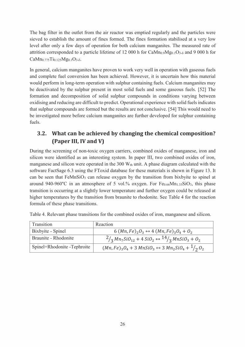
Table 4. Relevant phase transitions for the combined oxides of iron, manganese and silicon.
Transition Reaction Bixbyite - Spinel 6 ( , ) ↔ 4 ( , ) + Braunite - Rhodonite 2 3 + 4 ↔ 14 3 + Spinel+Rhodonite -Tephroite ( , ) + 3 ↔ 3 + 1 2
27
Figure 13. Phase diagram of MnO-FeO-SiO in an oxygen partial pressure of 5 vol.%. The molar fraction of silica was fixed at 33%. Silica is also present as various forms of SiO2, but these are not marked in the phase diagram. The dashed lines in the phase diagram represent the main effect of the presence of silica as it marks the transition to braunite. The vertical bold lines denote the composition of the oxygen carriers studied in paper III.
In paper IV, a similar phase diagram, seen in Figure 14, was calculated for the investigated materials, but in this case the temperature was fixed and the oxygen partial pressure was varied. The top of the diagram is representative of the conditions in the air reactor and the bottom of the diagram is representative for the conditions in the fuel reactor. It should be noted that Fe0.66Mn1.33SiO3 and F22M44S33 have the same chemical composition and are thus interchangeable in these phase diagrams. The phase transitions which could be relevant for chemical-looping conditions are bixbyite – spinel, braunite – rhodonite and possibly also spinel+rhodonite – tephroite for the materials with higher fractions of manganese, see Table 4.
Bi : Bixbyite, (MnxFe1-x)2O3 Br : Braunite, Mn7SiO12 H : Hematite, (FexMn1-x)2O3 R : Rhodonite, MnSiO3 S : Spinel, (MnxFe1-x)3O4
28
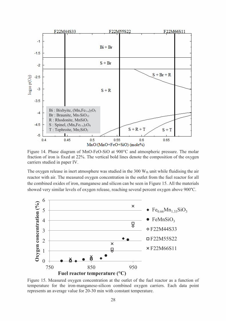
Figure 14. Phase diagram of MnO-FeO-SiO at 900°C and atmospheric pressure. The molar fraction of iron is fixed at 22%. The vertical bold lines denote the composition of the oxygen carriers studied in paper IV.
The oxygen release in inert atmosphere was studied in the 300 Wth unit while fluidising the air reactor with air. The measured oxygen concentration in the outlet from the fuel reactor for all the combined oxides of iron, manganese and silicon can be seen in Figure 15. All the materials showed very similar levels of oxygen release, reaching several percent oxygen above 900°C.
Figure 15. Measured oxygen concentration at the outlet of the fuel reactor as a function of temperature for the iron-manganese-silicon combined oxygen carriers. Each data point represents an average value for 20-30 min with constant temperature.
0
1
2
3
4
5
6
750 850 950
Oxy
gen
conc
entr
atio
n (%
)
Fuel reactor temperature (°C)
Fe0.66Mn1.33SiO3
MS2
F22M44S33
F22M55S22
F22M66S11
Fe0.66Mn1.33SiO3
FeMnSiO3
Bi : Bixbyite, (MnxFe1-x)2O3 Br : Braunite, Mn7SiO12 R : Rhodonite, MnSiO3 S : Spinel, (MnxFe1-x)3O4
T : Tephroite, Mn2SiO3
29
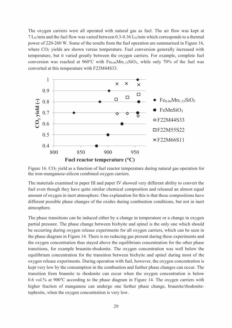
The oxygen carriers were all operated with natural gas as fuel. The air flow was kept at 7 LN/min and the fuel flow was varied between 0.3-0.36 LN/min which corresponds to a thermal power of 220-260 W. Some of the results from the fuel operation are summarised in Figure 16, where CO2 yields are shown versus temperature. Fuel conversion generally increased with temperature, but it varied greatly between the oxygen carriers. For example, complete fuel conversion was reached at 960°C with Fe0.66Mn1.33SiO3, while only 70% of the fuel was converted at this temperature with F22M44S33.
Figure 16. CO2 yield as a function of fuel reactor temperature during natural gas operation for the iron-manganese-silicon combined oxygen carriers.
The materials examined in paper III and paper IV showed very different ability to convert the fuel even though they have quite similar chemical composition and released an almost equal amount of oxygen in inert atmosphere. One explanation for this is that these compositions have different possible phase changes of the oxides during combustion conditions, but not in inert atmosphere.
The phase transitions can be induced either by a change in temperature or a change in oxygen partial pressure. The phase change between bixbyite and spinel is the only one which should be occurring during oxygen release experiments for all oxygen carriers, which can be seen in the phase diagram in Figure 14. There is no reducing gas present during these experiments and the oxygen concentration thus stayed above the equilibrium concentration for the other phase transitions, for example braunite-rhodonite. The oxygen concentration was well below the equilibrium concentration for the transition between bixbyite and spinel during most of the oxygen release experiments. During operation with fuel, however, the oxygen concentration is kept very low by the consumption in the combustion and further phase changes can occur. The transition from braunite to rhodonite can occur when the oxygen concentration is below 0.6 vol.% at 900°C according to the phase diagram in Figure 14. The oxygen carriers with higher fraction of manganese can undergo one further phase change, braunite/rhodonite-tephroite, when the oxygen concentration is very low.
0.4
0.5
0.6
0.7
0.8
0.9
1
800 850 900 950
CO
2yi
eld
(-)
Fuel reactor temperature (°C)
Fe0.66Mn1.33SiO3
FeMnSiO3
F22M44S33
F22M55S22
F22M66S11
Fe0.66Mn1.33SiO3
FeMnSiO3
30
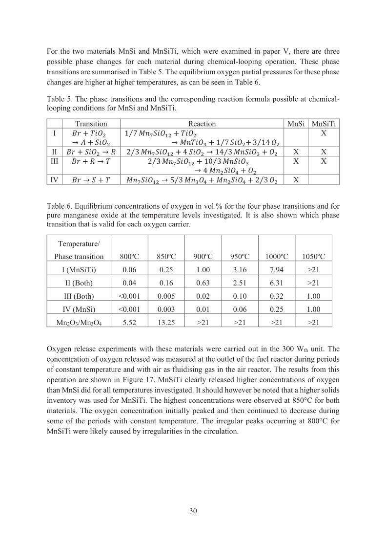
For the two materials MnSi and MnSiTi, which were examined in paper V, there are three possible phase changes for each material during chemical-looping operation. These phase transitions are summarised in Table 5. The equilibrium oxygen partial pressures for these phase changes are higher at higher temperatures, as can be seen in Table 6.
Table 5. The phase transitions and the corresponding reaction formula possible at chemical-looping conditions for MnSi and MnSiTi.
Transition Reaction MnSi MnSiTi I +→ +
1 7⁄ +→ + 1 7⁄ + 3 14⁄ X
II + → 2 3⁄ + 4 → 14 3⁄ + X X III + → 2 3⁄ + 10 3⁄→ 4 +
X X
IV → + → 5 3⁄ + + 2 3⁄ X
Table 6. Equilibrium concentrations of oxygen in vol.% for the four phase transitions and for pure manganese oxide at the temperature levels investigated. It is also shown which phase transition that is valid for each oxygen carrier.
Temperature/
Phase transition
800ºC
850ºC
900ºC
950ºC
1000ºC
1050ºC
I (MnSiTi) 0.06 0.25 1.00 3.16 7.94 >21
II (Both) 0.04 0.16 0.63 2.51 6.31 >21
III (Both) <0.001 0.005 0.02 0.10 0.32 1.00
IV (MnSi) <0.001 0.003 0.01 0.06 0.25 1.00
Mn2O3/Mn3O4 5.52 13.25 >21 >21 >21 >21
Oxygen release experiments with these materials were carried out in the 300 Wth unit. The concentration of oxygen released was measured at the outlet of the fuel reactor during periods of constant temperature and with air as fluidising gas in the air reactor. The results from this operation are shown in Figure 17. MnSiTi clearly released higher concentrations of oxygen than MnSi did for all temperatures investigated. It should however be noted that a higher solids inventory was used for MnSiTi. The highest concentrations were observed at 850°C for both materials. The oxygen concentration initially peaked and then continued to decrease during some of the periods with constant temperature. The irregular peaks occurring at 800°C for MnSiTi were likely caused by irregularities in the circulation.

31
Figure 17. Concentration of oxygen released for both oxygen carrier materials during periods with constant temperature.
It should be noted that both materials released oxygen concentrations above equilibrium at 800°C and at 850°C, see Table 6. This indicates that an additional phase transition other than those shown in Table 5 could have occurred. One possible oxide is pure Mn2O3 which could release oxygen by being reduced to Mn3O4 in the fuel reactor. As can be seen in Table 6, this phase transition has a much higher equilibrium oxygen partial pressure at these temperatures than the phase changes discussed above. Pure manganese oxide may be present if not all Mn3O4 reacted with the silica and titania during the sintering. This Mn3O4 could have been oxidised during the oxygen release experiment at 800°C as the oxygen concentration in the air reactor is high, typically up to 18 vol.%. The reoxidation of Mn3O4 is possible but likely slow at 850ºC because of the high equilibrium partial pressure. This could explain the continuous decrease in oxygen concentration released at the higher temperatures indicating that the oxygen carriers had not reached steady state.
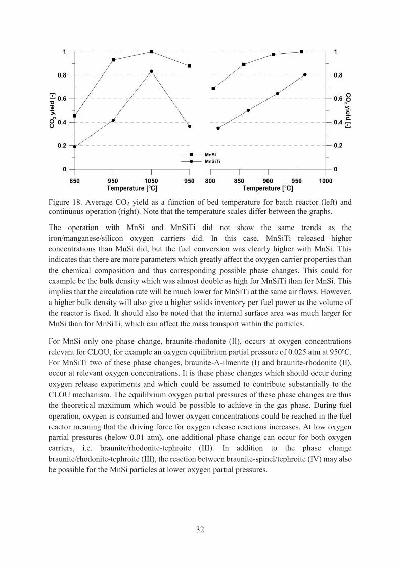
The oxygen carrier materials were examined with methane as fuel in the batch reactor and with natural gas in the 300 Wth unit. The CO2 yield during these experiments is shown in Figure 18 for the temperatures investigated. The average values for the batch experiments are calculated for 1 > ω > 0.99 and the average values for the continuous operation are calculated for the periods with constant temperature. The solids inventory was higher in the circulating reactor than during the batch experiments; 56 kg/MWth was used in the batch reactor and the solids inventory in the fuel reactor in the circulating reactor unit was 239 kg/MWth for MnSi and 355 kg/MWth for MnSiTi. The difference in solids inventory is likely to be the main reason why the fuel conversion was higher during the continuous operation. Anyhow, both experimental setups revealed the same trends with respect to temperature dependence and reactivity of the oxygen carriers.
MnSiTi
MnSi
32
Figure 18. Average CO2 yield as a function of bed temperature for batch reactor (left) and continuous operation (right). Note that the temperature scales differ between the graphs.
The operation with MnSi and MnSiTi did not show the same trends as the iron/manganese/silicon oxygen carriers did. In this case, MnSiTi released higher concentrations than MnSi did, but the fuel conversion was clearly higher with MnSi. This indicates that there are more parameters which greatly affect the oxygen carrier properties than the chemical composition and thus corresponding possible phase changes. This could for example be the bulk density which was almost double as high for MnSiTi than for MnSi. This implies that the circulation rate will be much lower for MnSiTi at the same air flows. However, a higher bulk density will also give a higher solids inventory per fuel power as the volume of the reactor is fixed. It should also be noted that the internal surface area was much larger for MnSi than for MnSiTi, which can affect the mass transport within the particles.
For MnSi only one phase change, braunite-rhodonite (II), occurs at oxygen concentrations relevant for CLOU, for example an oxygen equilibrium partial pressure of 0.025 atm at 950ºC. For MnSiTi two of these phase changes, braunite-A-ilmenite (I) and braunite-rhodonite (II), occur at relevant oxygen concentrations. It is these phase changes which should occur during oxygen release experiments and which could be assumed to contribute substantially to the CLOU mechanism. The equilibrium oxygen partial pressures of these phase changes are thus the theoretical maximum which would be possible to achieve in the gas phase. During fuel operation, oxygen is consumed and lower oxygen concentrations could be reached in the fuel reactor meaning that the driving force for oxygen release reactions increases. At low oxygen partial pressures (below 0.01 atm), one additional phase change can occur for both oxygen carriers, i.e. braunite/rhodonite-tephroite (III). In addition to the phase change braunite/rhodonite-tephroite (III), the reaction between braunite-spinel/tephroite (IV) may also be possible for the MnSi particles at lower oxygen partial pressures.
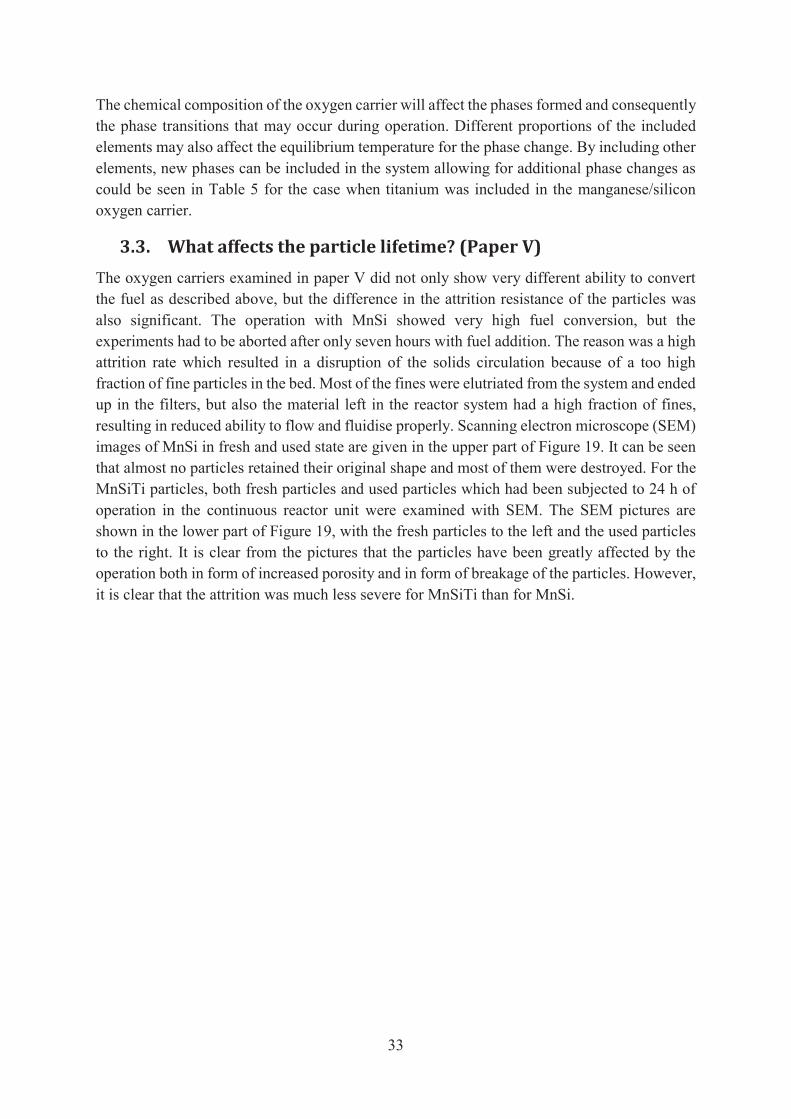
33
The chemical composition of the oxygen carrier will affect the phases formed and consequently the phase transitions that may occur during operation. Different proportions of the included elements may also affect the equilibrium temperature for the phase change. By including other elements, new phases can be included in the system allowing for additional phase changes as could be seen in Table 5 for the case when titanium was included in the manganese/silicon oxygen carrier.
3.3. What affects the particle lifetime? (Paper V) The oxygen carriers examined in paper V did not only show very different ability to convert the fuel as described above, but the difference in the attrition resistance of the particles was also significant. The operation with MnSi showed very high fuel conversion, but the experiments had to be aborted after only seven hours with fuel addition. The reason was a high attrition rate which resulted in a disruption of the solids circulation because of a too high fraction of fine particles in the bed. Most of the fines were elutriated from the system and ended up in the filters, but also the material left in the reactor system had a high fraction of fines, resulting in reduced ability to flow and fluidise properly. Scanning electron microscope (SEM) images of MnSi in fresh and used state are given in the upper part of Figure 19. It can be seen that almost no particles retained their original shape and most of them were destroyed. For the MnSiTi particles, both fresh particles and used particles which had been subjected to 24 h of operation in the continuous reactor unit were examined with SEM. The SEM pictures are shown in the lower part of Figure 19, with the fresh particles to the left and the used particles to the right. It is clear from the pictures that the particles have been greatly affected by the operation both in form of increased porosity and in form of breakage of the particles. However, it is clear that the attrition was much less severe for MnSiTi than for MnSi.
34
Figure 19. SEM images of MnSi (above) and MnSiTi (below) in fresh and used state.
The physical properties of MnSi and MnSiTi reported in Table 1 were measured again after operation in the batch reactor as well as after the continuous operation, see Table 7. However, it was not possible to measure the properties of MnSi operated in the continuous unit as almost all particles had turned into fines at the end of the operation. This is not really surprising as the attrition index measured for the fresh material was very high. The attrition index of MnSiTi was low for the fresh particles, but increased significantly during the continuous operation. This could be connected to the decrease in bulk density and increase in internal surface area. The particles appear to have swelled and have become more porous during operation. The crushing strength of MnSiTi, however, had increased after operation in the continuous unit.
fresh used
fresh used
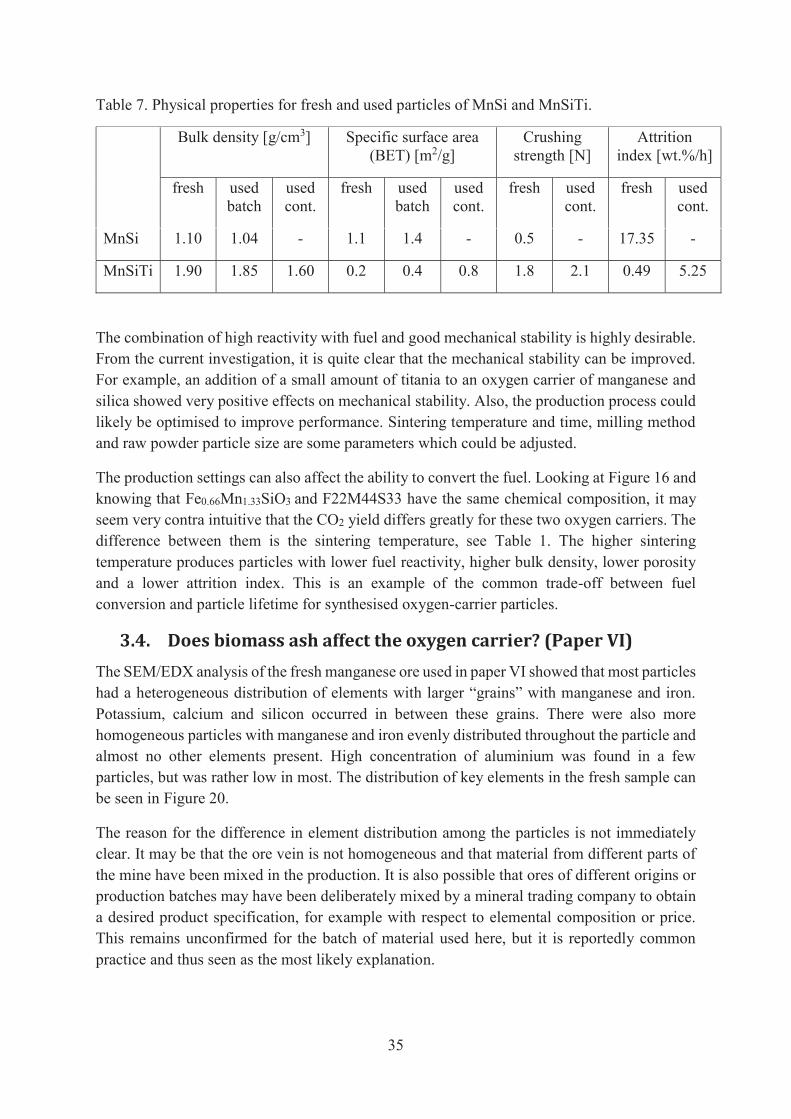
35
Table 7. Physical properties for fresh and used particles of MnSi and MnSiTi.
Bulk density [g/cm3] Specific surface area (BET) [m2/g]
Crushing strength [N]
Attrition index [wt.%/h]
fresh used batch
used cont.
fresh used batch
used cont.
fresh used cont.
fresh used cont.
MnSi 1.10 1.04 - 1.1 1.4 - 0.5 - 17.35 -
MnSiTi 1.90 1.85 1.60 0.2 0.4 0.8 1.8 2.1 0.49 5.25
The combination of high reactivity with fuel and good mechanical stability is highly desirable. From the current investigation, it is quite clear that the mechanical stability can be improved. For example, an addition of a small amount of titania to an oxygen carrier of manganese and silica showed very positive effects on mechanical stability. Also, the production process could likely be optimised to improve performance. Sintering temperature and time, milling method and raw powder particle size are some parameters which could be adjusted.
The production settings can also affect the ability to convert the fuel. Looking at Figure 16 and knowing that Fe0.66Mn1.33SiO3 and F22M44S33 have the same chemical composition, it may seem very contra intuitive that the CO2 yield differs greatly for these two oxygen carriers. The difference between them is the sintering temperature, see Table 1. The higher sintering temperature produces particles with lower fuel reactivity, higher bulk density, lower porosity and a lower attrition index. This is an example of the common trade-off between fuel conversion and particle lifetime for synthesised oxygen-carrier particles.
3.4. Does biomass ash affect the oxygen carrier? (Paper VI) The SEM/EDX analysis of the fresh manganese ore used in paper VI showed that most particles had a heterogeneous distribution of elements with larger “grains” with manganese and iron. Potassium, calcium and silicon occurred in between these grains. There were also more homogeneous particles with manganese and iron evenly distributed throughout the particle and almost no other elements present. High concentration of aluminium was found in a few particles, but was rather low in most. The distribution of key elements in the fresh sample can be seen in Figure 20.
The reason for the difference in element distribution among the particles is not immediately clear. It may be that the ore vein is not homogeneous and that material from different parts of the mine have been mixed in the production. It is also possible that ores of different origins or production batches may have been deliberately mixed by a mineral trading company to obtain a desired product specification, for example with respect to elemental composition or price. This remains unconfirmed for the batch of material used here, but it is reportedly common practice and thus seen as the most likely explanation.

36
Figure 20. Elemental distribution of manganese, iron, aluminium, potassium, calcium and silicon in the fresh manganese ore.
The bed samples taken each day of operation in the 12 MWth boiler were sent for elemental analysis to study to what extent ash components remained in the bed. The fresh manganese ore contained rather high fractions of common ash components such as silicon, calcium, potassium and magnesium, see Table 2. The elemental analysis showed that the concentration of these elements increased during operation, which can be seen in Figure 21. It is also observed that sulphur, which was not present in the fresh ore, has accumulated in the bed.
Figure 21. Concentration of common ash components in the bed particles as a function of operational time.
The elemental distribution of the sample taken after 52 h of operation is shown in Figure 22. Potassium, calcium and sulphur have accumulated at the surface of the particles, but potassium and sulphur have only attached to some particles. The particle without aluminium has the most
0
1
2
3
4
5
6
7
0 4 20 52 172
Con
cent
ratio
n (w
t%)
Operational time (h)
SiCaKMgS
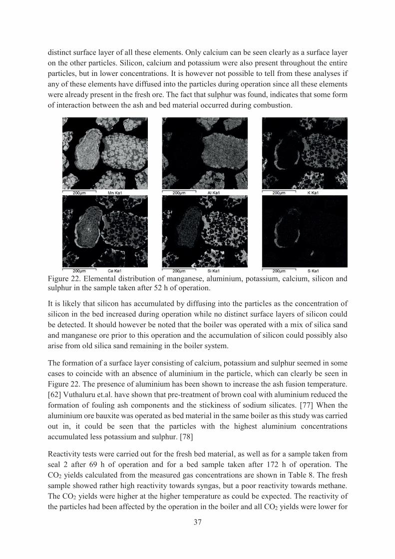
37
distinct surface layer of all these elements. Only calcium can be seen clearly as a surface layer on the other particles. Silicon, calcium and potassium were also present throughout the entire particles, but in lower concentrations. It is however not possible to tell from these analyses if any of these elements have diffused into the particles during operation since all these elements were already present in the fresh ore. The fact that sulphur was found, indicates that some form of interaction between the ash and bed material occurred during combustion.
Figure 22. Elemental distribution of manganese, aluminium, potassium, calcium, silicon and sulphur in the sample taken after 52 h of operation.
It is likely that silicon has accumulated by diffusing into the particles as the concentration of silicon in the bed increased during operation while no distinct surface layers of silicon could be detected. It should however be noted that the boiler was operated with a mix of silica sand and manganese ore prior to this operation and the accumulation of silicon could possibly also arise from old silica sand remaining in the boiler system.
The formation of a surface layer consisting of calcium, potassium and sulphur seemed in some cases to coincide with an absence of aluminium in the particle, which can clearly be seen in Figure 22. The presence of aluminium has been shown to increase the ash fusion temperature. [62] Vuthaluru et.al. have shown that pre-treatment of brown coal with aluminium reduced the formation of fouling ash components and the stickiness of sodium silicates. [77] When the aluminium ore bauxite was operated as bed material in the same boiler as this study was carried out in, it could be seen that the particles with the highest aluminium concentrations accumulated less potassium and sulphur. [78]
Reactivity tests were carried out for the fresh bed material, as well as for a sample taken from seal 2 after 69 h of operation and for a bed sample taken after 172 h of operation. The CO2 yields calculated from the measured gas concentrations are shown in Table 8. The fresh sample showed rather high reactivity towards syngas, but a poor reactivity towards methane. The CO2 yields were higher at the higher temperature as could be expected. The reactivity of the particles had been affected by the operation in the boiler and all CO2 yields were lower for

38
the used samples. The CO2 yields were lower after 172 h than after 69 h, indicating a continuous decrease in reactivity. It is, however, not clear if this decrease in reactivity is an effect of ash interactions with the oxygen carrier.
Table 8. CO2 yields for reactivity batch tests performed with syngas and methane.
[%] Syngas Methane 850°C 950°C 850°C 950°C Fresh ore 86.8 97.8 0.8 4.3 Seal 2 69 h 72.9 94.9 0.1 2.2 Bed 172 h 68.7 91.9 0.2 1.8
The use of a mineral ore as oxygen carrier for operation with solid fuels is motivated by the estimated cost. The presumed lifetime will likely be shortened due to fuel impurities and losses in separation of ash and oxygen carrier. At present, it is not clear whether the added cost of manufacturing materials will be compensated for by longer lifetime and better performance. It is therefore relevant to investigate naturally occurring materials such as manganese ores. Iron and silica are common constituents of manganese ores, which also means that they may be similar to the synthesised oxygen carriers investigated in this study, so the results from paper III-V are also relevant for a better understanding of the behaviour of manganese ores in chemical-looping combustion.

39
3.5. Outlook The work presented in this thesis was mostly carried out in chemical-looping reactor units with gaseous fuels. Many of the oxygen carriers examined could of course be used for combustion of solid fuels as well. However, it is not obvious that an oxygen carrier which work well with gaseous fuels will perform as good with solid fuels. Two of the spray-dried oxygen carriers from this work, CaMn0.9Mg0.1O3-δ and MnSiTi, have been operated with solid fuels in a 10 kWth chemical-looping reactor unit. Both materials provided higher gas conversion than for example ilmenite operated in the same unit. [50, 79] A manganese ore operated in a 100 kWth chemical-looping reactor unit have also shown performance superior to ilmenite in the same unit. [60] Even a rather small addition of manganese ore, up to 8 wt.%, during operation of ilmenite in this unit improved the fuel conversion. [59]
The results presented in this thesis together with the results for solid fuels mentioned above, show that manganese-based oxygen carriers are strong candidates for further development and up-scaling of chemical-looping combustion. Combined manganese oxides have numerous possibilities to achieve high performance, both in form of reactivity and mechanical stability, by adjusting chemical composition and synthesis parameters. However, it is a great challenge to find the best, or good enough, options without getting slowed down by an endless optimisation process.
For the use of natural materials, such as manganese ores, the possibilities and challenges are different. The great advantage is that the raw material itself can be utilised, which will lower the cost of the oxygen carrier compared to synthesised materials. The challenge lies in that this advantage will be lost if extensive pre-treatments of the material are necessary. This means that the many optimisation options available for synthesised materials, are not available.


41
4. Conclusions
Manganese combined oxides have been shown to have interesting properties for chemical-looping with oxygen uncoupling (CLOU). At the start of this work, only a limited number of experiments had been performed with these types of materials in continuous operation. In this work, ten oxygen carrier materials consisting of manganese oxides have been examined; seven synthesised materials in a 300 Wth unit, two synthesised materials in a 10 kWth unit and one manganese ore in a 12 MWth CFB boiler.
The main conclusions to draw from this operation are:
The manganese perovskite materials work very well in continuous operation with a low rate of attrition. The materials released high concentrations of oxygen and were able to fully convert the fuel at relevant temperature levels.
Combined oxides of iron, manganese and silica showed high fuel conversion and among those materials investigated, the material with the highest content of manganese had the highest fuel conversion. However, the mechanical stability of the particles was unsatisfactory.
Combined oxides of manganese and silica showed good performance. It was possible to reach full fuel conversion and it was possible to produce particles with significantly improved mechanical stability by adding titanium to the material. The addition of titania, however, lowered the gas conversion. The possibility to get good mechanical stability without compromising with the reactivity of the material needs to be further investigated.
Silicon, calcium, potassium, and sulphur accumulated in the bed during biomass combustion with a manganese ore as bed material. These elements could be found both inside the bed particles and in surface layers formed. The fresh ore particles varied in composition and it could be seen that particles comprising of a large amount of aluminium contained less ash elements at the surface than the particles with a low concentration of aluminium. The reactivity of the particles was continuously decreasing during operation in the boiler. However, the reactivity towards syngas was still high after more than seven days of continuous operation in the boiler.

43
Nomenclature
AR air reactor
BECCS bioenergy with carbon capture and storage
CCS carbon capture and storage
CFB circulating fluidised bed
CI circulation index (kg/min)
CLC chemical-looping combustion
CLOU chemical-looping combustion with oxygen uncoupling
EDX energy dispersive X-ray spectroscopy
Far air reactor gas flow (LN/min)
Ffr fuel reactor gas flow (LN/min)
FR fuel reactor
g gravitational acceleration (m/s²)
Gs net solid flux (kg/(m²min))
mox mass of fully oxidised oxygen carrier (g)
MO molar mass of oxygen (g/mol) n molar flow rate at the reactor outlet (mol/s)
OCAC oxygen carrier aided combustion
SEM scanning electron microscopy
xi gas concentration of species i (vol.%)
u superficial velocity (m/s)
ut terminal velocity of an average sized particle (m/s)
CO2 yield (-)
δ degree of oxygen deficiency in a perovskite structure (-)
ρexit solids concentration at the riser exit (kg/m3)
ω mass-based oxygen carrier conversion (-)

45
References
[1] IPCC. Climate Change 2013 The Physical Science Basis Working Group I Contribution to the Fifth Assessment Report of the Intergovernmental Panel on Climate Change. In: Stocker T, Qin D, Plattner G, Tignor M, Allen S, Boschung J, et al., editors. Cambridge, United Kingdom and New York, USA2013.
[2] Parmesan C, Yohe G. A globally coherent fingerprint of climate change impacts across natural systems. Nature. 2003;421:37-42.
[3] Walther GR, Post E, Convey P, Menzel A, Parmesan C, Beebee TJC, et al. Ecological responses to recent climate change. Nature. 2002;416:389-95.
[4] IPCC. Climate Change 2014: Mitigation of Climate Change. Contribution of Working Group III to the Fifth Assessment Report of the Intergovernmental Panel on Climate Change. In: Edenhofer O, Pichs-Madruga R, Sokona Y, Farahani E, Kadner S, Seyboth K, et al., editors. Cambridge, United Kingdom and New York, USA2014.
[5] Panwar NL, Kaushik SC, Kothari S. Role of renewable energy sources in environmental protection: A review. Renewable and Sustainable Energy Reviews. 2011;15:1513-24.
[6] IPCC. IPCC Special Report on Carbon Dioxide Capture and Storage. In: Metz B, Davidson O, de Coninck H, Loos M, Meyer L, editors. Cambridge, United Kingdom2005.
[7] Gasser T, Guivarch C, Tachiiri K, Jones CD, Ciais P. Negative emissions physically needed to keep global warming below 2°C. Nature Communications. 2015;6.
[8] Azar C, Lindgren K, Obersteiner M, Riahi K, van Vuuren DP, den Elzen KMGJ, et al. The feasibility of low CO2 concentration targets and the role of bio-energy with carbon capture and storage (BECCS). Climatic Change. 2010;100:195-202.
[9] Gough C, Upham P. Biomass energy with carbon capture and storage (BECCS or Bio-CCS). Greenhouse Gases: Science and Technology. 2011;1:324-34.
[10] Fuss S, Canadell JG, Peters GP, Tavoni M, Andrew RM, Ciais P, et al. COMMENTARY: Betting on negative emissions. Nature Climate Change. 2014;4:850-3.
[11] Boot-Handford ME, Abanades JC, Anthony EJ, Blunt MJ, Brandani S, Mac Dowell N, et al. Carbon capture and storage update. Energy Environ Sci. 2014;7:130-89.
[12] Mattisson T, Lyngfelt A, Leion H. Chemical-looping with oxygen uncoupling for combustion of solid fuels. International Journal of Greenhouse Gas Control. 2009;3:11-9.
[13] Lyngfelt A. Chemical-looping combustion of solid fuels - Status of development. Applied Energy. 2014;113:1869-73.
[14] Lewis WK, Gilliland ER. Production of pure carbon dioxide. In: patent U, editor. USA1954.
[15] Ishida M, Jin H. A novel combustor based on chemical-looping reactions and its reaction kinetics. Journal of Chemical Engineering of Japan. 1994;27:296-301.
[16] Lyngfelt A, Thunman H. Chapter 36 - Construction and 100 h of Operational Experience of A 10-kW Chemical-Looping Combustor. Carbon Dioxide Capture for Storage in Deep Geologic Formations. Amsterdam: Elsevier Science; 2005. p. 625-45.

46
[17] Lyngfelt A. Oxygen Carriers for Chemical Looping Combustion - 4 000 h of Operational Experience. Oil & Gas Science and Technology. 2011;66:2.
[18] Adanez J, Abad A, Garcia-Labiano F, Gayan P, de Diego LF. Progress in Chemical-Looping Combustion and Reforming technologies. Progress in Energy and Combustion Science. 2012;38:215-82.
[19] Fan LS, Zeng L, Wang W, Luo S. Chemical looping processes for CO2 capture and carbonaceous fuel conversion - Prospect and opportunity. Energy Environ Sci. 2012;5:7254-80.
[20] Nandy A, Loha C, Gu S, Sarkar P, Karmakar MK, Chatterjee PK. Present status and overview of Chemical Looping Combustion technology. Renewable and Sustainable Energy Reviews. 2016;59:597-619.
[21] Imtiaz Q, Hosseini D, Müller C. Review of Oxygen Carriers for Chemical Looping with Oxygen Uncoupling (CLOU): Thermodynamics, Material Development and Synthesis. Energy Technology. 2013;1:633-47.
[22] Abdulally, Iqbal, Beal, C Andrus H, Epple B, Lyngfelt A, et al. Alstom's Chemical Looping Prototypes, Program Update2012.
[23] Lyngfelt A, Linderholm C. Chemical-Looping Combustion of Solid Fuels - Status and Recent Progress. Energy Procedia2017. p. 371-86.
[24] Matzen M, Pinkerton J, Wang X, Demirel Y. Use of natural ores as oxygen carriers in chemical looping combustion: A review. International Journal of Greenhouse Gas Control. 2017;65:1-14.
[25] Jing D, Snijkers F, Hallberg P, Leion H, Mattisson T, Lyngfelt A. Effect of Production Parameters on the Spray-Dried Calcium Manganite Oxygen Carriers for Chemical-Looping Combustion. Energy and Fuels. 2016;30:3257-68.
[26] Jerndal E, Mattisson T, Lyngfelt A. Thermal Analysis of Chemical-Looping Combustion. Chemical Engineering Research and Design. 2006;84:795-806.
[27] Linderholm C, Mattisson T, Lyngfelt A. Long-term integrity testing of spray-dried particles in a 10-kW chemical-looping combustor using natural gas as fuel. Fuel. 2009;88:2083-96.
[28] Pröll T, Kolbitsch P, Bolhàr-Nordenkampf J, Hofbauer H. A novel dual circulating fluidized bed system for chemical looping processes. AIChE Journal. 2009;55:3255-66.
[29] Lyngfelt A, Mattisson T. Materials for chemical-looping combustion. Power Engineering for CCS Power Plants: WILEY-VCH Verlag; 2011.
[30] Abad A, Adánez-Rubio I, Gayán P, García-Labiano F, de Diego LF, Adánez J. Demonstration of chemical-looping with oxygen uncoupling (CLOU) process in a 1.5 kWth continuously operating unit using a Cu-based oxygen-carrier. International Journal of Greenhouse Gas Control. 2012;6:189-200.
[31] Penthor S, Zerobin F, Mayer K, Pröll T, Hofbauer H. Investigation of the performance of a copper based oxygen carrier for chemical looping combustion in a 120kW pilot plant for gaseous fuels. Applied Energy. 2015;145:52-9.

47
[32] Rydén M, Jing D, Källén M, Leion H, Lyngfelt A, Mattisson T. CuO-based oxygen-carrier particles for chemical-looping with oxygen uncoupling - Experiments in batch reactor and in continuous operation. Industrial and Engineering Chemistry Research. 2014;53:6255-67.
[33] He F, Linak WP, Deng S, Li F. Particulate Formation from a Copper Oxide-Based Oxygen Carrier in Chemical Looping Combustion for CO2 Capture. Environ Sci Technol. 2017;51:2482-90.
[34] Lambert A, Tilland A, Pelletant W, Bertholin S, Moreau F, Clemençon I, et al. Performance and degradation mechanisms of CLC particles produced by industrial methods. Fuel. 2018;216:71-82.
[35] Liang ZY, Dong CQ, Qin W, Lin CF. Review on optimization of iron based oxygen carriers in chemical-looping combustion. Xiandai Huagong/Modern Chemical Industry. 2017;37:36-40.
[36] Rydén M, Leion H, Mattisson T, Lyngfelt A. Combined oxides as oxygen-carrier material for chemical-looping with oxygen uncoupling. Applied Energy. 2013;113:1924-32.
[37] Shulman A, Cleverstam E, Mattisson T, Lyngfelt A. Manganese/Iron, Manganese/Nickel, and Manganese/Silicon Oxides Used in Chemical-Looping With Oxygen Uncoupling (CLOU) for Combustion of Methane. Energy & Fuels. 2009;23:5269-75.
[38] Azimi G, Leion H, Rydén M, Mattisson T, Lyngfelt A. Investigation of different Mn-Fe oxides as oxygen carrier for chemical-looping with oxygen uncoupling (CLOU). Energy and Fuels. 2013;27:367-77.
[39] Jing D, Arjmand M, Mattisson T, Rydén M, Snijkers F, Leion H, et al. Examination of oxygen uncoupling behaviour and reactivity towards methane for manganese silicate oxygen carriers in chemical-looping combustion. International Journal of Greenhouse Gas Control. 2014;29:70-81.
[40] Mattisson T, Jing D, Azimi G, Rydén M, Van Noyen J, Lyngfelt A. Using (MnxFe1-x)2SiO5 as oxygen carriers for chemical-looping with oxygen uncoupling (CLOU). Presented at AIChE Annual Meeting November 3-8, San Fransisco 2013. 2013.
[41] Rydén M, Lyngfelt A, Mattisson T. Combined manganese/iron oxides as oxygen carrier for chemical looping combustion with oxygen uncoupling (CLOU) in a circulating fluidized bed reactor system. Energy Procedia. 2011;4:341-8.
[42] Pérez-Vega R, Abad A, Gayán P, de Diego LF, García-Labiano F, Adánez J. Development of (Mn0.77Fe0.23)2O3 particles as an oxygen carrier for coal combustion with CO2 capture via in-situ gasification chemical looping combustion (iG-CLC) aided by oxygen uncoupling (CLOU). Fuel Processing Technology. 2017;164:69-79.
[43] Mungse P, Saravanan G, Rayalu S, Labhsetwar N. Mixed Oxides of Iron and Manganese as Potential Low-Cost Oxygen Carriers for Chemical Looping Combustion. Energy Technology. 2015;3:856-65.
[44] Larring Y, Braley C, Pishahang M, Andreassen KA, Bredesen R. Evaluation of a mixed Fe-Mn oxide system for chemical looping combustion. Energy and Fuels. 2015;29:3438-45.
[45] Leonidova EI, Leonidov IA, Patrakeev MV, Kozhevnikov VL. Oxygen non-stoichiometry, high-temperature properties, and phase diagram of CaMnO 3-δ. Journal of Solid State Electrochemistry. 2011;15:1071-5.
48
[46] Leion H, Larring Y, Bakken E, Bredesen R, Mattisson T, Lyngfelt A. Use of CaMn0.875Ti0.125O3 as oxygen carrier in chemical-looping with oxygen uncoupling. Energy and Fuels. 2009;23:5276-83.
[47] Hallberg P, Jing D, Rydén M, Mattisson T, Lyngfelt A. Chemical looping combustion and chemical looping with oxygen uncoupling experiments in a batch reactor using spray-dried CaMn1- xM xO3-δ (M = Ti, Fe, Mg) particles as oxygen carriers. Energy and Fuels. 2013;27:1473-81.
[48] Rydén M, Lyngfelt A, Mattisson T. CaMn0.875Ti0.125O3 as oxygen carrier for chemical-looping combustion with oxygen uncoupling (CLOU)—Experiments in a continuously operating fluidized-bed reactor system. International Journal of Greenhouse Gas Control. 2011;5:356-66.
[49] Hallberg P, Källén M, Jing D, Snijkers F, Van Noyen J, Rydén M, et al. Experimental investigation of CaMnO3-δ based oxygen carriers used in continuous chemical-looping combustion. Int J Chem Eng. 2014;2014.
[50] Schmitz M, Linderholm CJ. Performance of calcium manganate as oxygen carrier in chemical looping combustion of biochar in a 10 kW pilot. Applied Energy. 2016;169:729-37.
[51] Mayer K, Penthor S, Pröll T, Hofbauer H. The different demands of oxygen carriers on the reactor system of a CLC plant - Results of oxygen carrier testing in a 120 kWth pilot plant. Applied Energy. 2015;157:323-9.
[52] Arjmand M, Kooiman RF, Rydén M, Leion H, Mattisson T, Lyngfelt A. Sulfur tolerance of CaxMn1- yMyO 3-δ (M = Mg, Ti) perovskite-type oxygen carriers in chemical-looping with oxygen uncoupling (CLOU). Energy and Fuels. 2014;28:1312-24.
[53] Cabello A, Abad A, Gayán P, De Diego LF, García-Labiano F, Adánez J. Effect of operating conditions and H2S presence on the performance of CaMg0.1Mn0.9O3-δ perovskite material in chemical looping combustion (CLC). Energy and Fuels. 2014;28:1262-74.
[54] Schmitz M, Linderholm C, Lyngfelt A. Chemical Looping combustion of sulphurous solid fuels using spray-dried calcium manganate particles as oxygen carrier. In: Dixon T, Twinning S, Herzog H, editors. 12th International Conference on Greenhouse Gas Control Technologies, GHGT 2014: Elsevier Ltd; 2014. p. 140-52.
[55] Sundqvist S, Arjmand M, Mattisson T, Rydén M, Lyngfelt A. Screening of different manganese ores for chemical-looping combustion (CLC) and chemical-looping with oxygen uncoupling (CLOU). International Journal of Greenhouse Gas Control. 2015;43:179-88.
[56] Xu L, Sun H, Li Z, Cai N. Experimental study of copper modified manganese ores as oxygen carriers in a dual fluidized bed reactor. Applied Energy. 2016;162:940-7.
[57] Moldenhauer P, Sundqvist S, Mattisson T, Linderholm C. Chemical-looping combustion of synthetic biomass-volatiles with manganese-ore oxygen carriers. International Journal of Greenhouse Gas Control. 2018;71:239-52.
[58] Schmitz M, Linderholm C, Hallberg P, Sundqvist S, Lyngfelt A. Chemical-Looping Combustion of Solid Fuels Using Manganese Ores as Oxygen Carriers. Energy and Fuels. 2016;30:1204-16.
[59] Linderholm C, Schmitz M, Knutsson P, Lyngfelt A. Chemical-looping combustion in a 100-kW unit using a mixture of ilmenite and manganese ore as oxygen carrier. Fuel. 2016;166:533-42.
49
[60] Linderholm C, Schmitz M, Biermann M, Hanning M, Lyngfelt A. Chemical-looping combustion of solid fuel in a 100 kW unit using sintered manganese ore as oxygen carrier. International Journal of Greenhouse Gas Control. 2017;65:170-81.
[61] Khan AA, de Jong W, Jansens PJ, Spliethoff H. Biomass combustion in fluidized bed boilers: Potential problems and remedies. Fuel Processing Technology. 2009;90:21-50.
[62] Niu Y, Tan H, Hui S. Ash-related issues during biomass combustion: Alkali-induced slagging, silicate melt-induced slagging (ash fusion), agglomeration, corrosion, ash utilization, and related countermeasures. Progress in Energy and Combustion Science. 2016;52:1-61.
[63] Hupa M. Ash-related issues in fluidized-bed combustion of biomasses: Recent research highlights. Energy and Fuels. 2012;26:4-14.
[64] Rubel A, Zhang Y, Liu K, Neathery J. Effect of ash on Oxygen Carriers for the application of Chemical Looping Combustion. Oil Gas Sci Technol. 2011;66:291-300.
[65] Azis MM, Leion H, Jerndal E, Steenari BM, Mattisson T, Lyngfelt A. The Effect of Bituminous and Lignite Ash on the Performance of Ilmenite as Oxygen Carrier in Chemical-Looping Combustion. Chem Eng Technol. 2013;36:1460-8.
[66] Keller M, Arjmand M, Leion H, Mattisson T. Interaction of mineral matter of coal with oxygen carriers in chemical-looping combustion (CLC). Chemical Engineering Research and Design. 2014;92:1753-70.
[67] Bao J, Li Z, Cai N. Interaction between iron-based oxygen carrier and four coal ashes during chemical looping combustion. Applied Energy. 2014;115:549-58.
[68] Ilyushechkin AY, Kochanek M, Lim S. Interactions between oxygen carriers used for chemical looping combustion and ash from brown coals. Fuel Processing Technology. 2016.
[69] Gu H, Shen L, Zhong Z, Zhou Y, Liu W, Niu X, et al. Interaction between biomass ash and iron ore oxygen carrier during chemical looping combustion. Chemical Engineering Journal. 2015;277:70-8.
[70] Corcoran A, Marinkovic J, Lind F, Thunman H, Knutsson P, Seemann M. Ash properties of ilmenite used as bed material for combustion of biomass in a circulating fluidized bed boiler. Energy and Fuels. 2014;28:7672-9.
[71] Thunman H, Lind F, Breitholtz C, Berguerand N, Seemann M. Using an oxygen-carrier as bed material for combustion of biomass in a 12-MWth circulating fluidized-bed boiler. Fuel. 2013;113:300-9.
[72] Rydén M, Hanning M, Corcoran A, Lind F. Oxygen carrier aided combustion (OCAC) of wood chips in a semi-commercial circulating fluidized bed boiler using manganese ore as bed material. Appl Sci. 2016;6:1-19.
[73] Lind F, Corcoran A, Andersson B, Thunman H. 12,000 Hours of Operation with Oxygen-Carriers in Industrially Relevant Scale (75,000 kWth). VGB PowerTech. 2017.
[74] Rydén M, Moldenhauer P, Lindqvist S, Mattisson T, Lyngfelt A. Measuring attrition resistance of oxygen carrier particles for chemical looping combustion with a customized jet cup. Powder Technology. 2014;256:75-86.
50
[75] Berdugo Vilches T, Lind F, Rydén M, Thunman H. Experience of more than 1000 h of operation with oxygen carriers and solid biomass at large scale. Applied Energy. 2017;190:1174-83.
[76] Linderholm C, Abad A, Mattisson T, Lyngfelt A. 160 h of chemical-looping combustion in a 10 kW reactor system with a NiO-based oxygen carrier. International Journal of Greenhouse Gas Control. 2008;2:520-30.
[77] Vuthaluru HB, Domazetis G, Wall TF, Vleeskens JM. Reducing fly ash deposition by pretreatment of brown coal: Effect of aluminium on ash character. Fuel Processing Technology. 1996;46:117-32.
[78] Marinkovic J, Seemann M, Schwebel GL, Thunman H. Impact of Biomass Ash-Bauxite Bed Interactions on an Indirect Biomass Gasifier. Energy and Fuels. 2016;30:4044-52.
[79] Schmitz M, Linderholm CJ, Lyngfelt A. Chemical looping combustion of four different solid fuels using a manganese-silicon-titanium oxygen carrier. International Journal of Greenhouse Gas Control. 2018;70:88-96.