position mooring systems - safety4sea.com€¦ · fpi rules modu rules mou guide spm rules position...
TRANSCRIPT

G u i d e f o r P o s i t i o n M o o r i n g S y s t e m s
GUIDE FOR
POSITION MOORING SYSTEMS
MAY 2018
American Bureau of Shipping Incorporated by Act of Legislature of the State of New York 1862
2018 American Bureau of Shipping. All rights reserved. ABS Plaza 16855 Northchase Drive Houston, TX 77060 USA

F o r e w o r d
Foreword Mooring systems have been evolving in design, analysis, operating management and other areas to meet the challenges of safety and efficiency. ABS Rules and Guides are developed and updated to keep pace with the industry. This has resulted in a complex library of Rules and Guides. Many requirements are repeated throughout ABS Rules and Guides making use and maintenance of Rules/Guides more challenging. To address the duplication of requirements and provide a set of Rules/Guides that is easier to navigate, this Guide consolidates the latest classification requirements for position mooring systems.
In addition to the consolidation of the current requirements, this Guide also includes updates in the following areas based on the latest industry knowledge and experiences:
• Vortex Induced Motion (VIM) effect (8/3.7, 8/5.13)
• Bending-tension fatigue of mooring chains (3/7.5)
• Fiber rope mooring criteria (3/7.3)
• Mooring systems in squalls (3/3.5, 8/3.1, 8/5.11)
• Dynamically installed anchors (3/7.9, 6/5.7)
• Anchor holding capacity (6/5.7)
• Mooring analysis methodology (Section 8)
• Thruster-Assisted Mooring (Section 4)
This Guide supplements the following ABS Rules and Guides for issuing classification Notations relevant to position mooring systems:
• ABS Rules for Building and Classing Floating Production Installations (FPI Rules)
• ABS Rules for Building and Classing Mobile Offshore Drilling Units (MODU Rules)
• ABS Guide for Building and Classing Mobile Offshore Units (MOU Guide)
• ABS Rules for Building and Classing Single Point Moorings (SPM Rules)
• ABS Guide for Building and Classing Floating Offshore Liquefied Gas Terminals (FLGT Guide)
• ABS Rules for Building and Classing Offshore Support Vessels (OSV Rules)
• ABS Guide for the Classification Notation Thruster-Assisted Mooring (TAM, TAM-R, TAM (Manual)) For Mobile Mooring Systems (TAM Guide)
• ABS Guide for the Classification Symbols Pre-Laid Position Mooring Systems and Equipment for Mobile Offshore Units (Pre-Laid Guide)
ii ABS GUIDE FOR POSITION MOORING SYSTEMS . 2018

The following figure shows the relationship between this Guide and other ABS Rules/Guides/Guidance Notes:
FPI Rules MODU RulesMOU Guide SPM Rules
Position Mooring Guide(Mooring System Design Requirements)
Fiber Rope• ABS Fiber Rope
Guidance Notes
Wire Rope• API Spec 9A• API RP 9B
Chain & Accessory• ABS Offshore
Mooring Chain Guide
Anchors• ABS Materials Rules (Part 2)• ABS Drag Anchor & Plate
Anchor Guidance Notes
Onboard Hardware• ABS Steel Vessel
Rules for Á
This Guide focuses on design aspect of position mooring systems. Survey requirements remain in relevant Rules/Guides and are referenced in this Guide. The design requirements for position mooring systems will be removed from above mentioned Rules/Guides and replaced with references to this Guide on 1 July, 2019.
Before 1 July 2019, designers can choose to use this Guide or applicable Rules/Guides mentioned above. On 1 July 2019, TAM Guide and Pre-Laid Guide will be withdrawn and only this Guide will remain for the design of position mooring system.
Users are advised to check periodically on the ABS website www.eagle.org to verify that this version of this Guide is the most current.
We welcome your feedback. Comments or suggestions can be sent electronically by email to [email protected].
ABS GUIDE FOR POSITION MOORING SYSTEMS . 2018 iii
T a b l e o f C o n t e n t s
GUIDE FOR
POSITION MOORING SYSTEMS CONTENTS SECTION 1 Introduction ............................................................................................ 1
1 Objectives ........................................................................................... 1 3 Scope and Application ........................................................................ 1 5 ABS Rules and Guides References .................................................... 2 7 References of Industry Standards and Guidelines ............................. 3 9 Terms and Definitions of Mooring Systems ........................................ 4 11 Abbreviations ...................................................................................... 6
SECTION 2 Classification of Mooring Systems ....................................................... 8
1 General ............................................................................................... 8 3 Classification Notation ........................................................................ 8
3.1 Mooring System for Floating Production Installations ...................... 8 3.3 Mooring System for Floating Offshore Liquefied Gas Terminals ..... 8 3.5 Mooring System for Mobile Offshore Drilling Units, for Mobile
Offshore Units, for Offshore Supply Vessels ................................... 9 3.7 Mooring System for Mooring Terminals ........................................... 9
5 Documentation .................................................................................... 9 SECTION 3 Mooring System Design ....................................................................... 11
1 General ............................................................................................. 11 3 Environmental Criteria ...................................................................... 11
3.1 General .......................................................................................... 11 3.3 Design Environmental Conditions .................................................. 11 3.5 Environmental Data ....................................................................... 13 3.7 Mooring Location ........................................................................... 17
5 Mooring System Design Requirements ............................................ 18 5.1 Design Requirement ...................................................................... 18 5.3 Design Analysis ............................................................................. 19 5.5 Loading and Mooring System Conditions ...................................... 19 5.7 Summary of Mooring Analysis Conditions ..................................... 20
7 Mooring System Design Criteria ....................................................... 21 7.1 Offset of Moored Floating Structures/units .................................... 21 7.3 Mooring Line Tension .................................................................... 22 7.5 Mooring Line Fatigue ..................................................................... 22 7.7 Mooring Line Design Factor of Safety ............................................ 25 7.9 Mooring Anchor ............................................................................. 26
iv ABS GUIDE FOR POSITION MOORING SYSTEMS . 2018

7.11 Mooring between Vessel and Installation/Mooring Terminal ......... 27 7.13 Allowance for Corrosion and Wear ................................................ 28 7.15 Clearance ...................................................................................... 28
9 Mooring Line Monitoring ................................................................... 29 9.1 Mooring Line Failure Detection ...................................................... 29 9.3 Mooring Line Tension Monitoring for MODUs ............................... 29 9.5 Heading Monitoring of Moored Units ............................................. 29
TABLE 1 Mooring Analysis Conditions ................................................... 20 TABLE 2 M and K Value......................................................................... 23 TABLE 3 Strength Factor of Safety for Mooring Lines ........................... 25 TABLE 4 Fatigue Factor of Safety for Mooring Lines ............................. 25 TABLE 5 Factor of Safety for Anchor Holding Capacity ......................... 26 TABLE 6 Chain Corrosion and Wear Allowance .................................... 28 FIGURE 1 Direction of Wave Wind and Current Illustration ..................... 16
SECTION 4 Thruster-Assisted Mooring ................................................................. 30
1 Introduction ....................................................................................... 30 1.1 General.......................................................................................... 30 1.3 Application ..................................................................................... 30
3 Technical Requirements ................................................................... 30 3.1 Thruster-Assisted Mooring Design Criteria .................................... 30
5 System Requirements ....................................................................... 32 5.1 Mooring System ............................................................................ 32 5.3 Thruster Systems .......................................................................... 32 5.5 Power Systems ............................................................................. 33 5.7 Control and Monitoring System ..................................................... 33 5.9 Communications for Units with Thrust Assist Mooring System ...... 34
7 Failure Mode and Effect Analysis ..................................................... 34 9 Available Thrust ................................................................................ 34
9.1 Available Thrust for Thrusters ....................................................... 34 9.3 Thruster-Thruster Interaction ......................................................... 35 9.5 Thruster-Hull Interaction ................................................................ 35 9.7 Thruster-Current Interaction .......................................................... 35
11 Thruster Assisted Mooring Analysis Methodology ............................ 36 11.1 Mean Load Reduction ................................................................... 36 11.3 Time Domain Analysis Approach .................................................. 36
TABLE 1 Intact and Damaged TAM Definitions ..................................... 30 TABLE 2 Allowable Thrust for Thruster Assisted Mooring System ........ 31 TABLE 3 Mooring Line Factor of Safety ................................................. 32 FIGURE 1 Automatic Thruster Control Feedback Loop ........................... 36
ABS GUIDE FOR POSITION MOORING SYSTEMS . 2018 v

vi ABS GUIDE FOR POSITION MOORING SYSTEMS . 2018
SECTION 5 Pre-laid Stationkeeping Systems for Mobile Offshore Units ............ 37
1 Introduction ....................................................................................... 37
1.1 General .......................................................................................... 37
3 Technical Requirements ................................................................... 37
3.1 General .......................................................................................... 37
3.3 Class Notation (M-PL) ................................................................... 37
3.5 Class Notation (P-PL) .................................................................... 37
3.7 Class Notation TAM-PL (Manual) and TAM-PL ............................ 38
5 Plans and Particulars to be Submitted .............................................. 38
5.1 (P-PL) Notation .............................................................................. 38
5.3 TAM-PL and TAM-PL (Manual) Notations .................................... 39
SECTION 6 Mooring System Components ............................................................. 40
1 General ............................................................................................. 40
3 Mooring Lines ................................................................................... 40
3.1 Mooring Wire Rope ........................................................................ 40
3.3 Synthetic Fiber Mooring Rope ....................................................... 40
3.5 Mooring Chain and Accessories .................................................... 40
3.7 Other Components ........................................................................ 40
5 Anchors ............................................................................................. 41
5.1 Drag Anchor .................................................................................. 41
5.3 Driven Pile Anchor ......................................................................... 42
5.5 Plate Anchor .................................................................................. 43
5.7 Suction Piles .................................................................................. 43
5.9 Dynamically Installed Piles ............................................................ 43
5.11 Gravity Anchors ............................................................................. 44
7 Chain Stoppers ................................................................................. 44
9 Fairleads and Sheaves ..................................................................... 44
11 Winches and Windlasses .................................................................. 44
13 Quality Control .................................................................................. 44
15 Control Station .................................................................................. 45
17 Single Point Mooring Systems .......................................................... 45
17.1 Design Loadings ............................................................................ 45
17.3 Structural Components .................................................................. 45
17.5 Mechanical Components ............................................................... 45
17.7 Turret System ................................................................................ 46
17.9 Turret/Installation Structural Interface Loads ................................. 46
17.11 Submerged Buoys Structure .......................................................... 46
TABLE 1 Coefficient of Friction .............................................................. 42
SECTION 7 Surveys ................................................................................................. 48
1 General ............................................................................................. 48

SECTION 8 Mooring System Analysis .................................................................... 49 1 General ............................................................................................. 49 3 Environmental Load .......................................................................... 49
3.1 Wind Load ..................................................................................... 50 3.3 Current and Current Load .............................................................. 52 3.5 Current and Wind Load under Oblique Environment ..................... 53 3.7 Vortex Induced Motion .................................................................. 53 3.9 Wave and Wave Load ................................................................... 55 3.11 Wave Induced Motions of a Floating Unit ...................................... 55
5 Mooring System Analysis .................................................................. 56 5.1 General.......................................................................................... 56 5.3 Analysis Model .............................................................................. 56 5.5 Initial System Balance and Equilibrium Position ............................ 57 5.7 Response to Wave Frequency Force ............................................ 57 5.9 Response to Second-Order Low Frequency Force ....................... 58 5.11 Response to Squalls ..................................................................... 58 5.13 Response to VIM ........................................................................... 59 5.15 Multiple Vessels Interaction ........................................................... 60
7 Fatigue Damage ............................................................................... 60 7.1 General.......................................................................................... 60 7.3 Tension-Tension Fatigue Damage ................................................ 60 7.5 Bending-Tension Fatigue Damage ................................................ 62
TABLE 1 Height Coefficients Ch for Windages ....................................... 51 TABLE 2 Shape Coefficient .................................................................... 51 TABLE 3 Wind Velocity Conversion Factor ............................................ 52 TABLE 4 Line Drag Coefficient .............................................................. 53
APPENDIX 1 Available Thrust Assessment ............................................................. 63
1 General ............................................................................................. 63 3 Thrust at Bollard Pull ......................................................................... 63 5 Thruster-Thruster Interaction ............................................................ 64
5.1 In Line Tandem Condition ............................................................. 64 5.3 Upstream Thruster Turned Tandem Configuration ........................ 66 5.5 Forbidden Zones ........................................................................... 67
7 Thruster-Hull Interaction ................................................................... 68 7.1 Friction........................................................................................... 68 7.3 Coanda Effect ................................................................................ 68 7.5 Pontoon Blockage ......................................................................... 68 7.7 Tilted Thruster/Nozzle ................................................................... 68
9 Thruster-Current Interaction ............................................................. 69 TABLE 1 Range of Forbidden Zone for Different x/D ............................. 67 FIGURE 1 Open Propellers ...................................................................... 63 FIGURE 2 Ducted Propellers ................................................................... 64
ABS GUIDE FOR POSITION MOORING SYSTEMS . 2018 vii
FIGURE 3 Thrusters Configuration in Tandem Condition ........................ 65 FIGURE 4 Thrust Reduction of the Downstream Thruster in Open
Water ....................................................................................... 65 FIGURE 5 Thrusters Configuration in Tandem Condition Turning the
Upstream Thruster .................................................................. 66 FIGURE 6 Thrust Reduction of the Downstream Thruster Considering
Steering Angles of the Upstream Thruster ............................. 66 FIGURE 7 Range of Forbidden Zone ....................................................... 67 FIGURE 8 Thrust Reduction Ratio due to Hull Friction ............................ 68 FIGURE 9 Correction Factor, C, as the Function of the Tilt Angle of
the Propeller Shaft .................................................................. 69 FIGURE 10 Thrust Ratio for Ducted Propellers .......................................... 69 FIGURE 11 Thrust Ratio for Open Propellers ............................................ 70
APPENDIX 2 Vortex Induced Motion (VIM) ............................................................... 71
1 General ............................................................................................. 71 3 VIM Design Parameters .................................................................... 71
3.1 Susceptibility of VIM ...................................................................... 71 3.3 Reduced Velocity Vr ....................................................................... 72 3.5 Transverse (Cross Flow) VIM ........................................................ 72 3.7 Inline VIM ....................................................................................... 72
5 Strength Design ................................................................................ 73 5.1 VIM Design Amplitude ................................................................... 73 5.3 Strength Analysis Procedure ......................................................... 73
7 Fatigue Analysis ................................................................................ 74 7.1 Long Term Fatigue Damage .......................................................... 74 7.3 Single Extreme VIM Event ............................................................. 75
9 Model Testing ................................................................................... 75 9.1 Model Test Parameters ................................................................. 75
11 Methods to Improve Mooring Design for VIM ................................... 77 11.1 Polyester Rope for Middle Section................................................. 77 11.3 Improved Chain Fairlead ............................................................... 77 11.5 Strake Design ................................................................................ 77 11.7 Hull Appurtenances ....................................................................... 77 11.9 Tightened Mooring ......................................................................... 77
FIGURE 1 Example VIM Amplitude versus Reduced Velocity ................. 73
APPENDIX 3 Mooring Chain Fatigue Due to Bending ............................................. 78
1 General ............................................................................................. 78 3 Interlink Stiffness and Sliding Threshold ........................................... 78
3.1 Interlink Bending Moment and Contact Stiffness ........................... 78 3.3 Interlink Sliding Threshold ............................................................. 79
5 Tension-Bending Fatigue Analysis Approach ................................... 79
viii ABS GUIDE FOR POSITION MOORING SYSTEMS . 2018

7 Tension-Bending Fatigue Damage Calculation ................................ 80 7.1 Combined Stress Range ............................................................... 80 7.3 Stress Concentration Factors (SCFs) ............................................ 81 7.5 S-N Curve ...................................................................................... 82
9 Mitigation Method .............................................................................. 82 FIGURE 1 Interlink Out of Plane Bending (OPB) ..................................... 78 FIGURE 2 Chain Bending Moment vs Interlink Angle .............................. 79 FIGURE 3 Flow Chart to Calculate OPB Fatigue Damage ...................... 81
ABS GUIDE FOR POSITION MOORING SYSTEMS . 2018 ix

This Page Intentionally Left Blank
S e c t i o n 1 : I n t r o d u c t i o n
S E C T I O N 1 Introduction
1 Objectives This Guide provides criteria, technical requirements, and guidance on the design and analysis of position mooring systems. It supplements the following ABS Rules for issuing classification notations relevant to position mooring systems:
• ABS Rules for Building and Classing Floating Production Installations (FPI Rules)
• ABS Rules for Building and Classing Mobile Offshore Drilling Units (MODU Rules)
• ABS Rules for Building and Classing Single Point Moorings (SPM Rules)
• ABS Guide for Building and Classing Mobile Offshore Units (MOU Guide)
• ABS Guide for Building and Classing Floating Offshore Liquefied Gas Terminals (FLGT Guide)
• ABS Rules for Building and Classing Offshore Support Vessels (OSV Rules)
3 Scope and Application The mooring system provides position keeping to support the production and operation in the context of Rules and Guides mentioned above, and may be a part of the mandatory classification such as in the FPI Rules, or have a separate optional classification notation requested by the owner. This Guide provides detailed classification requirements for the mooring systems. The Guide is applicable to offshore position mooring systems including, but not limited to:
i) Spread mooring systems
ii) Turret mooring systems (internal turret and external turret)
iii) Catenary anchor leg mooring (CALM) systems
iv) Single anchor leg mooring (SALM) systems
v) Disconnectable mooring systems
vi) Pre-laid mooring systems
vii) Thruster-assisted mooring systems
The Guide does not cover the tendon systems for Tension Leg Platforms (TLP).
The main components of the mooring system include:
i) Mooring line
• Chain, wire rope, synthetic rope, or a combination
• Clump weight
• Spring buoy
• Connecting hardware (shackle, swivel, other connectors)
ABS GUIDE FOR POSITION MOORING SYSTEMS . 2018 1

Section 1 Introduction
ii) Winching equipment
• Windlass
• Chain jack
• Drum-type winch
• Linear winch
• Traction winch
• Fairlead and stopper
iii) Anchoring system
• Drag Embedment Anchors
• Pile Anchors (driven, jetted, drilled and grouted)
• Dynamically installed piles
• Suction pile and Suction Caisson
• Gravity Anchor
• Plate Anchor (drag embedded and direct embedded)
• Suction embedded plate anchor (SEPLA)
iv) Where applicable, the mooring system may also include the following
• Turret for turret mooring systems
• Disconnection system for disconnectable mooring systems
• Thrusters and thruster control systems for thruster-assisted mooring systems
5 ABS Rules and Guides References In addition to this Guide and the ABS Rules and Guides listed in Subsection 1/1, the following ABS Rules and Guides are applicable to related components of the position mooring systems:
• ABS Guide for the Certification of Offshore Mooring Chain (Offshore Mooring Chain Guide)
• ABS Guidance Notes on the Application of Fiber Ropes for Offshore Mooring (Fiber Rope Guidance Notes)
• ABS Rules for Building and Classing Offshore Installations (Offshore Installations Rules)
• ABS Guide for Fatigue Assessment of Offshore Structures
• ABS Guide for Dynamic Positioning Systems (DPS Guide)
Following two Guidance Notes provide recommendations and best practices for anchors:
• ABS Guidance Notes on Design and Installation of Dynamically Installed Piles
• ABS Guidance Notes on Design and Installation of Drag Embedment Anchor and Plate Anchor
2 ABS GUIDE FOR POSITION MOORING SYSTEMS . 2018
Section 1 Introduction
7 References of Industry Standards and Guidelines The Industry standards and Guidelines given below, as well as other recognized standards, may provide acceptable methods for fulfilling the requirements in this Guide provided that the methods can achieve the same or a higher level of safety required in this Guide.
• API RP 2SK: Recommended practice for design and analysis of Station Keeping systems for floating structures.
• API RP 2SM: Design, Manufacture, Installation, and Maintenance of Synthetic Fiber Ropes for Offshore Mooring.
• API RP 2FPS: Recommended Practice for Planning, Designing, and Constructing Floating Production Systems
• API RP 2MET: Derivation of Metocean Design and Operating Conditions
• API RP 2GEO: Geotechnical and Foundation Design Considerations
• API Spec 9A: Specification for Wire Rope
• API RP 2I: Recommended Practice for In-service Inspection of Mooring Hardware for Floating Structures.
• ISO 19901-7:2005: Stationkeeping systems for floating offshore structures and mobile offshore units.
• ISO 19904-1: Floating Offshore Structures – Part 1: Monohulls, Semi-submersibles and Spars
• ISO 1704:2008: Shipbuilding - Stud-link anchor chains
• ISO 2232:1990: Round drawn wire for general purpose non-alloy steel wire ropes and for large diameter steel wire ropes – Specifications.
• ISO 10425:2003: Steel wire ropes for the petroleum and natural gas industries – Minimum requirements and terms of acceptance.
• ISO 18692: Fibre ropes for offshore stationkeeping – Polyester.
• ISO/TS 17920: Fibre ropes for offshore stationkeeping -- Aramid
• ISO TS 14909: Fibre ropes for offshore stationkeeping – High modulus polyethylene (HMPE)
• ISO/TS 19336: Fibre ropes for offshore station keeping – Polyarylate
• NORSOK N-001: Integrity of Offshore Structures
• NORSOK N-005: Condition Monitoring of Load Bearing Structures
• HSE Offshore Installation Moorings (IS 4/2013): UK HSE Offshore Information Sheet No. 4/2013
• HSE Research Report 444: Floating Production System (FPS) Joint Industry Project (JIP) FPS Mooring Integrity
• HSE FPSO-Mooring Inspection (SN-3/2005): Floating Production Storage and Offloading (FPSO) –Mooring Inspection
• UK Mooring Integrity Guidance (MIG): UK Mooring Integrity Guidance
• NOPSEMA: Offshore Petroleum and Greenhouse Gas Storage (Safety) Regulations 2009
• BSEE NTL 2008-G09: Guidelines for Moored Drilling Rig Fitness Requirements for Hurricane Season
• BSEE NTL 2009-G03: Synthetic Mooring Systems
• OCIMF: Mooring Equipment Guidelines (MEG3), Oil Companies International Marine Forum
ABS GUIDE FOR POSITION MOORING SYSTEMS . 2018 3
Section 1 Introduction
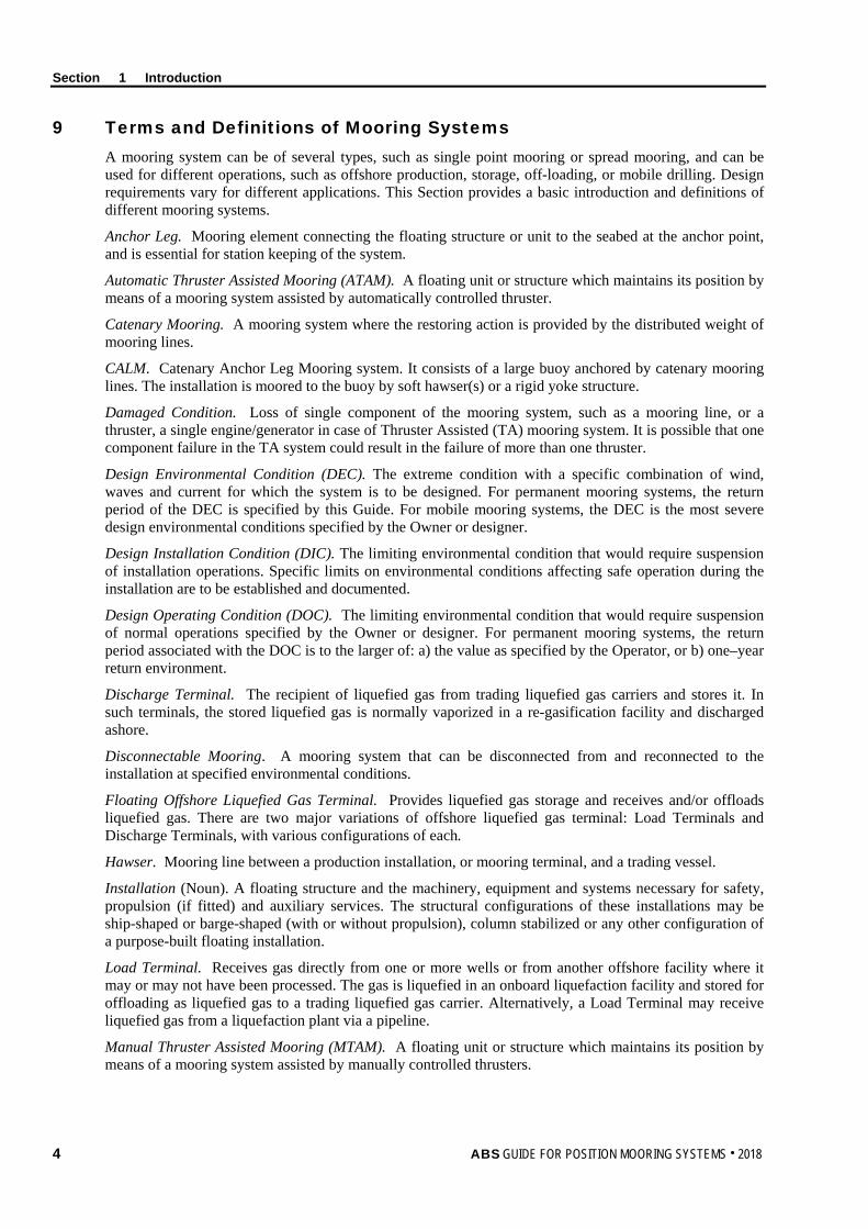
9 Terms and Definitions of Mooring Systems A mooring system can be of several types, such as single point mooring or spread mooring, and can be used for different operations, such as offshore production, storage, off-loading, or mobile drilling. Design requirements vary for different applications. This Section provides a basic introduction and definitions of different mooring systems.
Anchor Leg. Mooring element connecting the floating structure or unit to the seabed at the anchor point, and is essential for station keeping of the system.
Automatic Thruster Assisted Mooring (ATAM). A floating unit or structure which maintains its position by means of a mooring system assisted by automatically controlled thruster.
Catenary Mooring. A mooring system where the restoring action is provided by the distributed weight of mooring lines.
CALM. Catenary Anchor Leg Mooring system. It consists of a large buoy anchored by catenary mooring lines. The installation is moored to the buoy by soft hawser(s) or a rigid yoke structure.
Damaged Condition. Loss of single component of the mooring system, such as a mooring line, or a thruster, a single engine/generator in case of Thruster Assisted (TA) mooring system. It is possible that one component failure in the TA system could result in the failure of more than one thruster.
Design Environmental Condition (DEC). The extreme condition with a specific combination of wind, waves and current for which the system is to be designed. For permanent mooring systems, the return period of the DEC is specified by this Guide. For mobile mooring systems, the DEC is the most severe design environmental conditions specified by the Owner or designer.
Design Installation Condition (DIC). The limiting environmental condition that would require suspension of installation operations. Specific limits on environmental conditions affecting safe operation during the installation are to be established and documented.
Design Operating Condition (DOC). The limiting environmental condition that would require suspension of normal operations specified by the Owner or designer. For permanent mooring systems, the return period associated with the DOC is to the larger of: a) the value as specified by the Operator, or b) one–year return environment.
Discharge Terminal. The recipient of liquefied gas from trading liquefied gas carriers and stores it. In such terminals, the stored liquefied gas is normally vaporized in a re-gasification facility and discharged ashore.
Disconnectable Mooring. A mooring system that can be disconnected from and reconnected to the installation at specified environmental conditions.
Floating Offshore Liquefied Gas Terminal. Provides liquefied gas storage and receives and/or offloads liquefied gas. There are two major variations of offshore liquefied gas terminal: Load Terminals and Discharge Terminals, with various configurations of each.
Hawser. Mooring line between a production installation, or mooring terminal, and a trading vessel.
Installation (Noun). A floating structure and the machinery, equipment and systems necessary for safety, propulsion (if fitted) and auxiliary services. The structural configurations of these installations may be ship-shaped or barge-shaped (with or without propulsion), column stabilized or any other configuration of a purpose-built floating installation.
Load Terminal. Receives gas directly from one or more wells or from another offshore facility where it may or may not have been processed. The gas is liquefied in an onboard liquefaction facility and stored for offloading as liquefied gas to a trading liquefied gas carrier. Alternatively, a Load Terminal may receive liquefied gas from a liquefaction plant via a pipeline.
Manual Thruster Assisted Mooring (MTAM). A floating unit or structure which maintains its position by means of a mooring system assisted by manually controlled thrusters.
4 ABS GUIDE FOR POSITION MOORING SYSTEMS . 2018
Section 1 Introduction
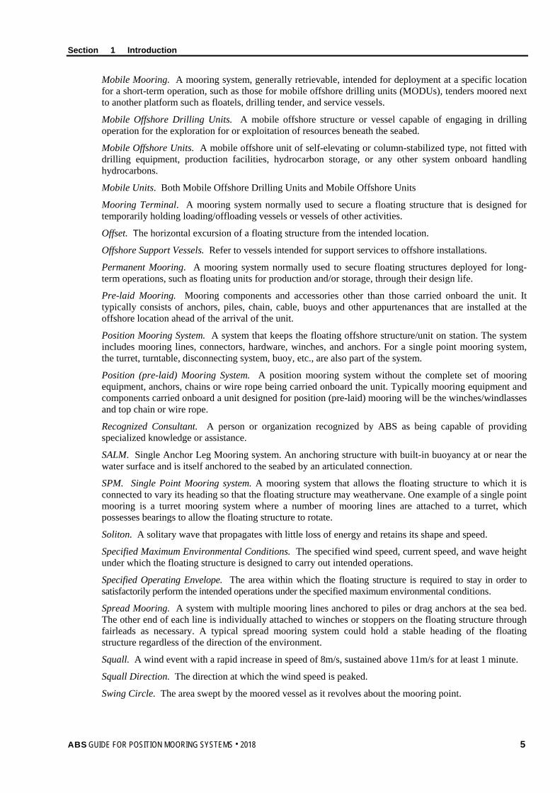
Mobile Mooring. A mooring system, generally retrievable, intended for deployment at a specific location for a short-term operation, such as those for mobile offshore drilling units (MODUs), tenders moored next to another platform such as floatels, drilling tender, and service vessels.
Mobile Offshore Drilling Units. A mobile offshore structure or vessel capable of engaging in drilling operation for the exploration for or exploitation of resources beneath the seabed.
Mobile Offshore Units. A mobile offshore unit of self-elevating or column-stabilized type, not fitted with drilling equipment, production facilities, hydrocarbon storage, or any other system onboard handling hydrocarbons.
Mobile Units. Both Mobile Offshore Drilling Units and Mobile Offshore Units
Mooring Terminal. A mooring system normally used to secure a floating structure that is designed for temporarily holding loading/offloading vessels or vessels of other activities.
Offset. The horizontal excursion of a floating structure from the intended location.
Offshore Support Vessels. Refer to vessels intended for support services to offshore installations.
Permanent Mooring. A mooring system normally used to secure floating structures deployed for long-term operations, such as floating units for production and/or storage, through their design life.
Pre-laid Mooring. Mooring components and accessories other than those carried onboard the unit. It typically consists of anchors, piles, chain, cable, buoys and other appurtenances that are installed at the offshore location ahead of the arrival of the unit.
Position Mooring System. A system that keeps the floating offshore structure/unit on station. The system includes mooring lines, connectors, hardware, winches, and anchors. For a single point mooring system, the turret, turntable, disconnecting system, buoy, etc., are also part of the system.
Position (pre-laid) Mooring System. A position mooring system without the complete set of mooring equipment, anchors, chains or wire rope being carried onboard the unit. Typically mooring equipment and components carried onboard a unit designed for position (pre-laid) mooring will be the winches/windlasses and top chain or wire rope.
Recognized Consultant. A person or organization recognized by ABS as being capable of providing specialized knowledge or assistance.
SALM. Single Anchor Leg Mooring system. An anchoring structure with built-in buoyancy at or near the water surface and is itself anchored to the seabed by an articulated connection.
SPM. Single Point Mooring system. A mooring system that allows the floating structure to which it is connected to vary its heading so that the floating structure may weathervane. One example of a single point mooring is a turret mooring system where a number of mooring lines are attached to a turret, which possesses bearings to allow the floating structure to rotate.
Soliton. A solitary wave that propagates with little loss of energy and retains its shape and speed.
Specified Maximum Environmental Conditions. The specified wind speed, current speed, and wave height under which the floating structure is designed to carry out intended operations.
Specified Operating Envelope. The area within which the floating structure is required to stay in order to satisfactorily perform the intended operations under the specified maximum environmental conditions. Spread Mooring. A system with multiple mooring lines anchored to piles or drag anchors at the sea bed. The other end of each line is individually attached to winches or stoppers on the floating structure through fairleads as necessary. A typical spread mooring system could hold a stable heading of the floating structure regardless of the direction of the environment.
Squall. A wind event with a rapid increase in speed of 8m/s, sustained above 11m/s for at least 1 minute.
Squall Direction. The direction at which the wind speed is peaked.
Swing Circle. The area swept by the moored vessel as it revolves about the mooring point.
ABS GUIDE FOR POSITION MOORING SYSTEMS . 2018 5

Section 1 Introduction
Taut-line Mooring. A mooring system where the restoring action is provided by elastic deformation of mooring lines.
Thruster Assisted Mooring. A mooring system assisted by onboard thrusters and thruster control systems to provide position keeping for a floating structure. The thrusters may be used to control the heading of the floating structure and reduce mooring load.
Turret Mooring. A system consisting of a number of mooring legs attached to a turret, which includes bearings to allow the floating structure to rotate around the anchor legs so that the installation may weathervane. The turret may be mounted internally within the installation or externally from the installation bow or stern. Typically, a spread mooring arrangement connects the turret to the seabed.
Yoke Arm. A structure at the end of the installation that only allows angular relative movement between the installation and the mooring attachment to the seabed.
11 Abbreviations ABS American Bureau of Shipping
ALS Accidental limit state
API American Petroleum Institute
CALM Catenary anchor leg mooring
DIN Dissolved nitrogen
DEC Design Environmental Condition
DIC Design Installation Condition
DISEC DISconneting Environmental Condition
DOC Design Operating Condition
DOFs Degree-of-freedoms
DPS Dynamic Positioning Systems.
FEM Finite element method
FLS Fatigue limit states
FMEA Failure modes and effects analysis
FOS Factor of safety
FPIs Floating production installations
FPS Floating production system
FPSO Floating production storage and offloading
HMPE High modulus polyethylene
IPB In-plane bending
JIP Joint Industry Project
MBS Minimum breaking strength
MIC Microbiologically influenced corrosion
MIG Mooring integrity guidance
MODU Mobile Offshore Drilling Units
MOU Mobile Offshore Unit
NDT Nondestructive testing
OCIMF Oil Companies International Marine Forum
6 ABS GUIDE FOR POSITION MOORING SYSTEMS . 2018
Section 1 Introduction
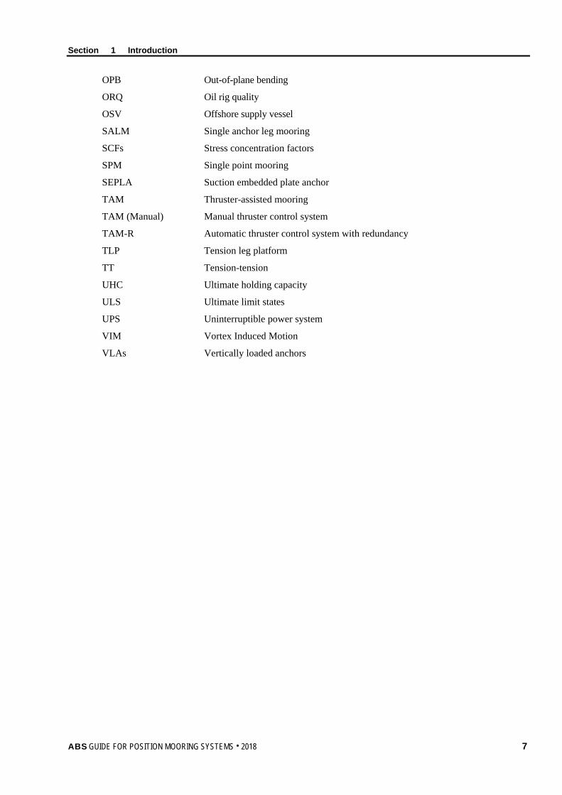
OPB Out-of-plane bending
ORQ Oil rig quality
OSV Offshore supply vessel
SALM Single anchor leg mooring
SCFs Stress concentration factors
SPM Single point mooring
SEPLA Suction embedded plate anchor
TAM Thruster-assisted mooring
TAM (Manual) Manual thruster control system
TAM-R Automatic thruster control system with redundancy
TLP Tension leg platform
TT Tension-tension
UHC Ultimate holding capacity
ULS Ultimate limit states
UPS Uninterruptible power system
VIM Vortex Induced Motion
VLAs Vertically loaded anchors
ABS GUIDE FOR POSITION MOORING SYSTEMS . 2018 7

S e c t i o n 2 : C l a s s i f i c a t i o n o f M o o r i n g S y s t e m s
S E C T I O N 2 Classification of Mooring Systems
1 General ABS classifies mooring systems based on the function types of the floating structure/unit that the mooring system is designed for. The floating structures/units can be categorized into three types:
• Production Installation: An installation for production, storage and offloading
• Mobile Unit: A floating structure intended to be frequently relocated to perform a particular function, such as mobile drilling units, offshore construction support vessels, accommodation units, service floating units etc.
• Mooring Terminal: A floating structure, such as a buoy, that provides temporary offshore mooring to a variety of visiting vessels, such as shuttle tankers for loading or offloading gas or liquid products, by means of a hawser or yoke from the buoy.
This Section describes the ABS classification notations for these three types of mooring systems and the ABS Rules and Guides that provide relevant classification requirements.
3 Classification Notation
3.1 Mooring System for Floating Production Installations For Floating Production Installations (FPIs), there is no separate class notation for the mooring system. The installation’s class notations cover a position mooring system that meets the requirements of the FPI Rules and this Guide. Examples are:
Floating Production, Storage and Offloading System (hull type) Floating Production (and Offloading) System (hull type) Floating Storage and Offloading System (hull type)
In addition, ABS also provides the classification notation (Disconnectable) to indicate that a floating installation system has a propulsion system and a means of disengaging the installation from its mooring and riser systems to allow the installation to ride out severe weather or seek refuge under its own power for a specified design environmental condition.
3.3 Mooring System for Floating Offshore Liquefied Gas Terminals For a Floating Offshore Liquefied Gas Terminals, there is no separated class notation for the mooring system. Vessel’s class notations, such as F(LPG), F(LNG/LPG), etc., cover the position mooring system that meets the requirements of the FLGT Guide and this Guide.
8 ABS GUIDE FOR POSITION MOORING SYSTEMS . 2018

Section 2 Classification of Mooring Systems
ABS GUIDE FOR POSITION MOORING SYSTEMS . 2018 9
3.5 Mooring System for Mobile Offshore Drilling Units, for Mobile Offshore Units, for Offshore Supply Vessels For a Mobile Offshore Drilling Unit (MODU), a Mobile Offshore Unit (MOU), and an Offshore Support Vessel (OSV), the following optional notions for the mooring system can be provided if requested by the owner.
Â: Indicates that the mooring equipment, anchors, chain or wire rope which have been specified by the Owner for position mooring have been tested in accordance with the specifications of the Owner and in the presence of a Surveyor.
Ã: Indicates that the mooring system has the position mooring capability of the unit under owner specified environmental conditions and meets the requirements specified in this Guide.
TAM: Indicates that the combined mooring and thruster systems is capable of automatically maintaining the position and heading of the unit under owner specified maximum environmental conditions and meets the requirements specified in this Guide.
TAM-R: Indicates that the combined mooring and thruster systems is capable of automatically maintaining the position and heading of the unit under owner specified maximum environmental conditions, thruster system meets the requirements specified in this Guide including redundancy.
TAM (Manual): Indicates the combined mooring and thruster system is capable of maintaining the position and heading of the unit under owner specified maximum environmental conditions, thruster system is manually controlled and meets the requirements specified in this Guide.
(P-PL): Indicates that the mooring equipment and components carried onboard a unit and designed for the pre-laid position mooring system has the positioning mooring capability of the unit, when hooked up with pre-laid mooring components, under owner specified environmental conditions and meets the requirements specified in this Guide.
(M-PL): Indicates that the mooring equipment, chain or wire rope (carried onboard the unit) which has been specified by the Owner for position (pre-laid) mooring have been tested in accordance with the specifications of the Owner and in the presence of a Surveyor.
TAM-PL: Indicates a pre-laid system fitted with a TA system that can operate automatically. The system is capable of automatically maintaining the position and heading of the unit under specified maximum environmental conditions and meet the requirements of this Guide.
TAM-PL (Manual): Indicates a pre-laid systems fitted with a TA system that is manually operated by a TA operator. The system is capable maintaining the position and heading of the unit under specified maximum environmental conditions and meet the requirements of this Guide.
3.7 Mooring System for Mooring Terminals For a mooring terminal, there is no separated notation for the mooring system. The terminal’s class notation of Single Point Mooring covers the mooring system that meets the SPM Rules and this Guide.
5 Documentation The submitted documents for review are to include all design data, system components, analysis reports, and other documents that are sufficiently detailed to demonstrate the adequacy of the mooring design.
The design documentation for the mooring system is to include the following, when applicable:
i) Mooring arrangement or pattern
ii) Details of winching equipment
iii) Details of anchoring system
iv) Details of mooring line segments
v) Connections at anchors and between mooring line segments
Section 2 Classification of Mooring Systems
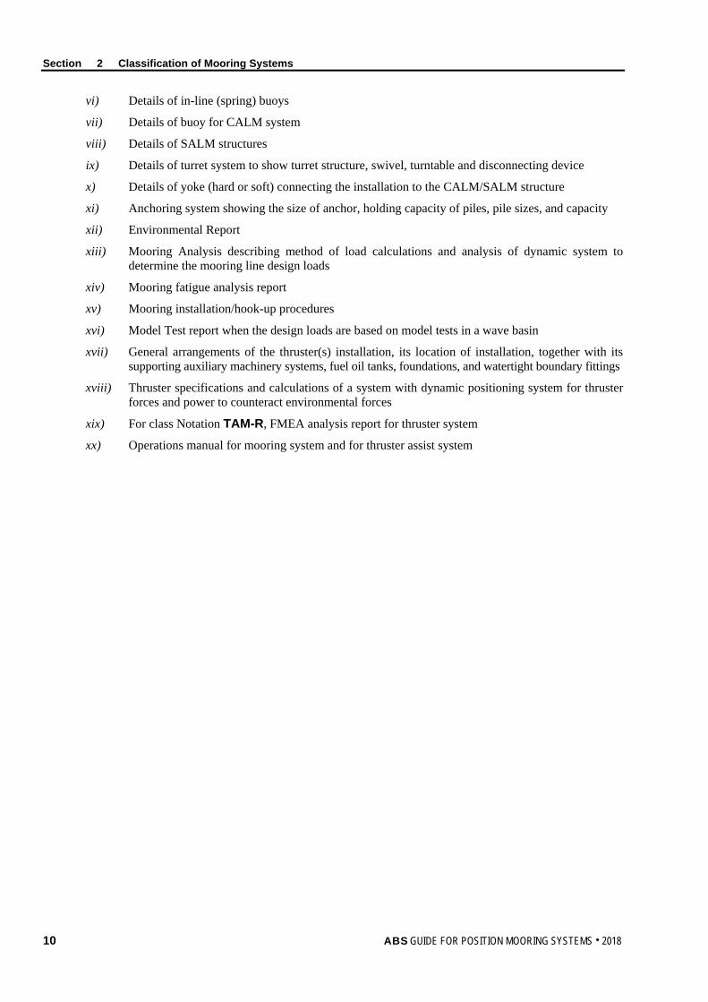
vi) Details of in-line (spring) buoys
vii) Details of buoy for CALM system
viii) Details of SALM structures
ix) Details of turret system to show turret structure, swivel, turntable and disconnecting device
x) Details of yoke (hard or soft) connecting the installation to the CALM/SALM structure
xi) Anchoring system showing the size of anchor, holding capacity of piles, pile sizes, and capacity
xii) Environmental Report
xiii) Mooring Analysis describing method of load calculations and analysis of dynamic system to determine the mooring line design loads
xiv) Mooring fatigue analysis report
xv) Mooring installation/hook-up procedures
xvi) Model Test report when the design loads are based on model tests in a wave basin
xvii) General arrangements of the thruster(s) installation, its location of installation, together with its supporting auxiliary machinery systems, fuel oil tanks, foundations, and watertight boundary fittings
xviii) Thruster specifications and calculations of a system with dynamic positioning system for thruster forces and power to counteract environmental forces
xix) For class Notation TAM-R, FMEA analysis report for thruster system
xx) Operations manual for mooring system and for thruster assist system
10 ABS GUIDE FOR POSITION MOORING SYSTEMS . 2018

S e c t i o n 3 : M o o r i n g S y s t e m D e s i g n
S E C T I O N 3 Mooring System Design
1 General This Section provides requirements related to the design of a mooring system for the class notations described in Subsection 2/3 of this Guide. Requirements as specified in the Rules and Guide given in Subsections 1/1, and 1/5 are also applicable. This Section includes design criteria for the mooring systems and the methodology for evaluation and verification of the mooring systems.
3 Environmental Criteria
3.1 General The environmental criteria, in general, are established based on the following:
i) The type of structure being designed
ii) The phase of development (e.g., construction, transportation, installation, drilling, or production)
iii) The performance considered
iv) The design environmental conditions for restricted exposure levels, when appropriate, are based on the consequences of failures of a mooring system. In this Guide, mooring systems are categorized into following three groups according to their intended operations:
• Mooring systems for floating production, storage, and offloading installations
• Mooring systems for mobile offshore units, mobile offshore drilling units, and offshore support vessels
• Mooring systems for floating mooring terminals
3.3 Design Environmental Conditions 3.3.1 General
For a position mooring system, where applicable, the following environmental conditions are to be considered:
i) Design Environmental Condition (DEC). The extreme condition with a specific combination of wind, waves and current for which the system is to be designed.
ii) Design Operating Condition (DOC). The limiting environmental condition that would require suspension of normal operations.
iii) Design Installation Condition (DIC). The limiting environmental condition that would require suspension of installation operations.
3.3.2 Mooring Systems for Floating Production Installations 3.3.2(a) Design Environmental Condition (DEC). The DEC is to be one of the following combinations that results in the most severe loading case:
i) 100-year waves with associated wind and current
ii) 100-year wind with associated waves and current
iii) 100-year current with associated waves and wind
ABS GUIDE FOR POSITION MOORING SYSTEMS . 2018 11

Section 3 Mooring System Design
In areas where the maximum mooring system responses are governed by squalls, 100-year squalls with the following combination are also to be included for the DEC:
iv) 100-year squalls with associated wind seas and 1-year current.
In areas with high current, additional design environmental load cases may require consideration.
A minimum return period of 50 years will be specially considered if it is accepted by the coastal state. Any environmental combinations with return periods shorter than that of the 100-year DEC which may induce larger mooring load responses are also to be used in the design.
For a Floating Installation with a Disconnectable notation, the Disconnecting Environmental Condition (DISEC) of the mooring system is the limiting extreme environmental condition at which the installation is to be disconnected from the mooring system. The DISEC condition is not to be taken as less severe than the environmental condition based on 10-year return period. In tropical revolving storm areas, the 100-year “sudden” tropical cyclone (hurricane or typhoon) which may form near the site of the installation may be considered instead of a fully developed storm for this evaluation. The permanent mooring system (i.e., the mooring system alone (without the installation)), is to be designed to withstand an environmental condition based on a 100-year return period. An acceptable monitoring system is to be provided for tracking environmental conditions or mooring line tensions in order to assist in the decision to disconnect the installation from the mooring system.
3.3.2(b) Design Operating Condition (DOC). The return period associated with the DOC is to be the larger of:
i) The value as specified by the Operator
ii) One year
3.3.2(c) Design Installation Condition (DIC). Specific limits on environmental conditions affecting safe operation during the installation phases are to be established and documented.
3.3.2(d) Fatigue Environmental Condition. For the long term fatigue analysis, a set of environmental states, such as wave scatter diagram data of wave height/period joint occurrence distribution, are to be specified, to cover the range of conditions and allow the calculation of fatigue damage with adequate accuracy.
3.3.3 Mooring Systems for Mobile Offshore Units (MOUs), Mobile Offshore Drilling Units (MODUs), Offshore support Vessels (OSVs) For MOUs, MODUs, and OSVs, the Owner is to specify the environmental conditions for which the plans for the unit are to be approved. These design environmental conditions are to be recorded in the Operations Manual. The following environment conditions are to be specified:
3.3.3(a) Design Operating Condition (DOC). The most severe design environmental conditions for normal operations specified by the Owner or designer.
3.3.3(b) Design Environmental Condition (DEC). The most severe design environmental conditions for survival specified by the Owner or designer.
3.3.4 Floating Mooring Terminals 3.3.4(a) Design Environmental Condition (DEC). The Design Environmental Condition for a mooring system of a floating mooring terminal is defined as the environmental condition with maximum wind, waves, and associated currents based on a 100-year return period. In this condition, no vessel is moored to the mooring terminal, unless the system is specifically designed for this situation. Alternatively, the DECs for Floating Production Installations can be used.
3.3.4(b) Design Operating Condition (DOC). The Design Operating Condition for a mooring system of a floating mooring terminal is defined as the maximum sea state in which a vessel is permitted to remain moored to the terminal. Wind, waves, and the associated currents used in the design are specified by the owner or designer.
12 ABS GUIDE FOR POSITION MOORING SYSTEMS . 2018
Section 3 Mooring System Design
3.5 Environmental Data 3.5.1 General
The environmental conditions for various design conditions described in Subsection 3/3 of this Guide are to be submitted with adequate data for the specific site of operation. Statistical data and mathematical models that describe the range of expected variations of environmental conditions are to be employed. All data used are to be fully documented with the sources and estimated reliability of data noted.
An environmental report describing methods employed in developing available data into design criteria is to be submitted in accordance with Subsection 2/5 of this Guide. Probabilistic methods for short-term, long-term and extreme-value prediction are to employ statistical distributions appropriate to the environmental phenomena being considered, as evidenced by relevant statistical tests, confidence limits and other measures of statistical significance. Hindcasting methods and models are to be fully documented.
For areas where the design is governed by special weather events, which may not be well represented by typical return period statistics, such as squalls, such special weather events are also to be taken into consideration when determining the environmental conditions.
Generally, data and analyses supplied by recognized consultants will be accepted as the basis of design. Relevant published design standards and data, if available, may be cited in documentation.
For mobile mooring systems, the design environment conditions are specified by the owners. The required information specified in 3/3.5 may not applicable to mobile mooring systems.
3.5.2 Waves Extreme wave events of Design Environmental Condition (DEC) and Design Operation Condition (DOC) are to be provided, including both winter storms and tropical cyclones (hurricanes or typhoons) where applicable. The environmental report is to provide the following wave statistics for the site of installation:
i) Significant wave height
ii) A range of associated wave periods is to be considered for each specified significant wave height
iii) Long period swell and direction, where applicable
iv) Wave spectral shape formulation
v) Wave height/period joint occurrence distribution (wave scatter diagram data with equal annual probability of occurrence for each data point)
vi) Long-term wave statistics by direction
For each design sea state, a long-crested sea without spectral energy spreading is normally considered in the mooring analysis.
3.5.3 Wind The wind conditions for various design conditions are to be established from collected wind data and are to be consistent with other environmental parameters assumed to occur simultaneously. In general, the wind speed is to be based on a return required for the DECs.
The environmental report is to present wind statistics for the site of installation and operation. The statistics are to be based on the analysis and interpretation of wind data by a recognized consultant. The report is to include a wind rose or table showing the frequency distributions of wind velocity and direction and a table or graph showing the recurrence period of extreme winds. The percentage of time for which the operational phase limiting wind velocity is expected to be exceeded during a year and during the worst month or season is to be identified. Extreme wind events of Design Environmental Condition (DEC) and Design Operation Condition (DOC) of following are to be provided where applicable. The following wind statistics for the site of installation are to be provided:
ABS GUIDE FOR POSITION MOORING SYSTEMS . 2018 13

Section 3 Mooring System Design
i) Wind speed of 1-minute average at 10m above sea level
ii) Steady wind speed of 1-hour mean wind at 10m above sea level
iii) Suitable wind gust spectrum
iv) Long-term wind direction statistics
3.5.4 Squall A squall is a strong transient wind event characterized by sudden rapid increases in wind speed and sudden shifts in wind direction. The environmental report is to present squall statistics for the site of installation and operation. The statistics are to be based on the analysis and interpretation of squall data by a recognized consultant. Extreme squall events of Design Environmental Condition (DEC) of the following are to be provided where applicable.
i) Squall events and it’s time history of wind speed and wind direction
ii) Statistics of squall direction. The squall direction is defined as the direction at which the wind speed is peaked
When the information on extreme squall events of Design Environment Condition with a 100-year return period are not available, the following method can be used to determine the characteristics of a 100-year squall.
3.5.4(a) 100-year Squalls. 100-year squalls can be established by scaling the wind speeds of selected squall events as given in below. The maximum wind speed of a squall event is to be scaled to the wind speed associated with 100-year return period of a given metocean site.
V100(ti) = max
100
VV V(ti) m/s (ft/s)
where
V100(ti) = wind speed at time i of scaled 100-year squall, in m/sec (ft/s)
V(ti) = wind speed at time i of a squall record, in m/sec (ft/sec)
V100 = wind speed with 100-year return period, in m/sec (ft/sec)
Vmax = maximum wind speed of a squall record, in m/sec (ft/sec)
The method can be applied to other number of years return squalls, say N-year squall.
3.5.4(b) Squall Direction. The wind direction of one minute mean of a squall time record can be in any direction. The direction of a squall in this Guide is defined as the wind direction corresponding to the maximum wind speed in a squall time record. If there is no information on squall direction, it can be assumed that the squall can come from any direction. The critical squall directions given in 3/3.3.6 should be considered in mooring analysis.
3.5.5 Current For the extreme current events of Design Environmental Condition (DEC) and Design Operation Condition (DOC), the following data is to be provided where applicable. The following current statistics for the site of installation are to be presented:
i) Current speed and directional variation through the water depth
ii) Long-term current direction statistics
The vector sum of the currents may include following components:
i) Tidal currents (associated with astronomical tides)
ii) Circulation currents (loop and eddy currents)
iii) Storm-generated currents
iv) Soliton currents
14 ABS GUIDE FOR POSITION MOORING SYSTEMS . 2018

Section 3 Mooring System Design
3.5.6 Angular Separation of Wind, Current and Waves For single point mooring systems, which allow the moored floating structure to weathervane, both collinear and non-collinear directions among wind, current and waves are to be considered. Proper angular separation for the DEC of wind, current and waves is to be determined based on the site-specific environmental study. If this information is not available, the following two angular combinations for non-collinear environments can be considered as a minimum:
i) Wind and current are collinear and both at 30 degrees to waves.
ii) Wind at 30 degrees to waves and current at 90 degrees to waves. For wave condition dominated design, the angular separation between current and waves may be reduced from 90 degrees, but is to be no less than 45 degrees.
Section 3, Figure 1 illustrates one example of wind, wave and current directions.
For spread mooring systems with limited change in installation heading angles (less than 20 degrees) under design environmental loads, the design cab be based solely on the collinear environments of wind, current and waves, which are generally controlling.
For a squall-dominated environment, the following conditions are to be considered.
Squall directions, as well as current and wave directions of site specific information can be used for the mooring analysis. If such information is not available, below guidelines can be followed.
For a spread mooring system, a co-linear condition, (squall, current and waves are in same direction), can be considered. Mooring analysis should include following directions as minimum:
i) Squall direction in each mooring line group
ii) Squall direction is beam-on a moored unit
For a single point mooring, in addition to the co-linear condition, following additional conditions are also to be considered.
i) Current and waves are collinear and both at 30 degrees to squall.
ii) Waves at 30 degrees to squall and current at 90 degrees to squall.
iii) Waves at 180 degrees, current 90 degrees, squall initial direction (direction at the initial time step of a squall) in 0-degree, 30-degree and 60-degree from stern, respectively
The initial squall direction for the analysis case considered should be shifted accordingly as follows.
θi(t0) = θ(t0) – θ(tmax) – βi degrees
where
θi(t0) = initial squall direction for the analysis case i, degrees
θ(t0) = initial squall direction at first time step, degrees
θ(tmax) = squall direction defined as at the maximum wind speed of a squall, degrees
βi = specified direction for analysis case i, such as the direction of a mooring line group, etc.
ABS GUIDE FOR POSITION MOORING SYSTEMS . 2018 15

Section 3 Mooring System Design
FIGURE 1 Direction of Wave Wind and Current Illustration
Wave Direction
y
βx Wave
Wind/Squall
Current
3.5.7 Water Depth The design water depth for the mooring system is to account for sea level variations due to tides, storm surges, and seafloor subsidence, if applicable.
Tidal data is to be based on astronomical tides and storm surge. The astronomical tidal extremes and tidal means for the mooring site are to be established. Sufficient data is to be submitted to establish the validity of the tide data. Tide levels may preferably be determined from records of a tide gauge in the vicinity of the site or from published tide tables for a location in the vicinity of the site. If the location from which the tide data is obtained is from a remote mooring site, a transformation of the tide data to the mooring site is to be performed by a recognized consultant. The seasonality of extreme tidal variations should be considered when considering the combination of astronomical tide and storm surge.
The maximum storm surge for the mooring site is to be established if the mooring is in a coastal or estuary location. Sufficient data is to be submitted to establish the validity of this storm surge.
Maximum storm surge may preferably be determined from tide records taken near the location. If the location from which the tide data is obtained is remote from the mooring site, a transformation of the tide data to the mooring site is to be performed by a recognized consultant. Storm surge hindcasts for design (extreme) storms performed by a recognized consultant may be submitted.
3.5.8 Seiche The location of the mooring site in relation to seiche nodal points is to be investigated by a recognized consultant if the site is in a basin or other area known for seiche action. Seiche is defined as a standing wave in a basin or partially enclosed body of water due to wind, waves, atmospheric pressure, or earthquake. Mooring sites located at or near seiche nodal points may be influenced by currents not otherwise predicted. If the mooring site is at or near a seiche nodal point, currents induced by seiche are to be reflected in the operating current and maximum current, and the influence of the period of the current on the dynamic response of the moored vessel is to be considered.
3.5.9 Temperatures and Ice Where drift ice may be a hazard to a mooring or to a vessel navigating to or moored at a mooring or to floating hoses at a mooring, an analysis of the nature and degree of this hazard is to be submitted.
When air temperature and precipitation, spray, or tidal action may combine to cause substantial ice formation on the mooring, an analysis of the degree to which ice may form and how this ice may affect the performance of the mooring is to be submitted.
The structure, equipment, hoses/flexible risers, component parts and their respective material which may be affected by low temperatures are to be examined.
16 ABS GUIDE FOR POSITION MOORING SYSTEMS . 2018

Section 3 Mooring System Design
3.5.10 Marine Growth The type and accumulation rate of marine growth at the design site can affect mass, weight, hydrodynamic diameters, and drag coefficients of floating structure members and mooring lines. Marine growth is to be taken into consideration for permanent mooring systems not subject to any regular marine growth removal.
3.7 Mooring Location 3.7.1 Site Chart
A complete chart of the mooring area is to be submitted. This chart is to show depth soundings and obstructions within the swing circle, the maneuvering area, and where applicable, the approach channel from deep water or an established navigation channel. The chart may be based on local charts published by government agencies or on hydrographic surveys conducted by a recognized consultant. In the case of charts based on hydrographic surveys, a survey report is to be submitted describing the surveying method, equipment, and personnel employed to conduct the survey.
The exact location and water depth of the mooring base and each anchor point, is to be indicated on the chart. If the mooring is associated with other SPMs in the area, or with a pumping or control platform, these features are to be indicated on the chart. All other features and water use areas which may present potential navigational hazards are to be identified. All existing and planned navigation aids such as lights, buoys, and shore markers which will be used in conjunction with the mooring are to be indicated and identified on the chart.
3.7.2 Swing Circle For a loading/offloading mooring terminal, the swing circle as defined in Subsection 1/9 of this Guide is to be indicated and captioned on the site chart. The radius of the swing circle is the sum of the horizontal excursion of the mooring systems from its center position under operating hawser load and minimum tide, the horizontal projection of the length of the hawser under operating hawser load, the length overall of the largest vessel for which the mooring system is designed, with an additional safety allowance of 30 m (100 ft).
3.7.3 Water Depth Requirement For a loading/offloading mooring terminal, the water depth at any place within the maneuvering area is to be such that no vessel using the mooring terminal system will make contact with the sea floor or any object on the sea bottom in any sea condition under which such a vessel is expected to be present as outlined in the design premises within the maneuvering area.
The designer may elect to specify limiting drafts for various vessel sizes when the proposed water depth is not sufficient to allow a vessel of the maximum size to be moored in the maneuvering area under the design operating environmental condition.
The determination of the required water depth is to be based upon calculations, data from model tests or full scale trials, designers' experience, or other available sources of information.
The designer is to submit evidence to demonstrate to the satisfaction of ABS that in determining the required water depth, the following factors have been considered:
i) Vessel’s dimensions and other relevant characteristics
ii) Wave height, wave period, and compass direction with respect to the vessel
iii) The prevailing wind and astronomical tides
iv) The expected vessel's heaving, rolling and pitching and vessel under keel clearance of at least 1 meter (3.3 feet)
v) The consistency of the sea bottom material or the character of any protrusion from the sea bottom
vi) The level of accuracy of the depth survey data
vii) Predicted variation of seabed profile due to sediment transport during the design life, where applicable.
ABS GUIDE FOR POSITION MOORING SYSTEMS . 2018 17
Section 3 Mooring System Design
3.7.4 Soil Condition In general, site investigation is to be in accordance with Section 3-2-5 of the Offshore Installations Rules. Soil data is to be taken from the vicinity of the foundation system site. An interpretation of this data is to be submitted by a recognized geotechnical consultant. To establish the soil characteristics of the site, foundation system borings or probings are to be taken at all foundation locations to a suitable depth. This depth is to be of at least the anticipated depth of any piles or anchor penetrations plus a consideration for the soil variability. As an alternative, sub-bottom profile runs may be taken and correlated with at least two borings or probings in the vicinity of anchor locations and an interpretation may be made by a recognized geotechnical consultant to adequately establish the soil profile at all anchoring locations.
5 Mooring System Design Requirements
5.1 Design Requirement 5.1.1 Functional Requirement
A mooring system is to be designed to restrict the offset of a floating structure/unit within prescribed limits, as well as to maintain the directionality when the structure’s orientation is important for safety or operational considerations.
The limiting criteria for offset and orientation are generally established either by the owner of the floating structure/unit or directly derived from design requirements including those related to:
i) Safety of personnel
ii) Stability of the floating structure
iii) Serviceability of the floating structure, and intended operations
iv) Drilling riser and production riser requirements
v) Access to and clearances with respect to nearby installations
vi) Any other special positioning requirement
Other mooring system design requirements, to include: i) Contact of connectors with soil
ii) Contact of synthetic rope with soil
iii) Uplift at anchor where applicable
iv) Clashing of mooring lines
v) Synthetic rope minimum tension, where applicable
5.1.2 Strength and Fatigue Capacity Requirement The mooring system and its components are to be designed to withstand environmental and other external forces under the environmental conditions specified in Subsection 3/3 of this Guide. They are to be designed with consideration given to the following limit states.
i) Ultimate Limit States (ULS). The mooring system and its components are to be designed to have adequate strength to withstand the load resulted from extreme environmental conditions.
ii) Fatigue Limit States (FLS). The mooring system and its components, where applicable, are to be designed to have adequate capacity to withstand the cyclic load due to exposure environments.
iii) Accidental limit state (ALS). The mooring system and its components, where applicable, are to be designed to have adequate capacity to withstand the load resulting from extreme environmental conditions when the mooring system loses any one of the mooring lines, or thrusters for thruster assisted mooring systems.
18 ABS GUIDE FOR POSITION MOORING SYSTEMS . 2018

Section 3 Mooring System Design
5.3 Design Analysis The design requirements given in 3/5.1 of this Guide for the excursion/offset of a moored offshore structure/unit and the strength and fatigue capacity of the mooring line components can be evaluated by engineering analysis with methodologies provided in this section. Other industry guidelines may be used provided those methods can achieve the same level of, or better results, than the methods in this section. The detailed analysis considerations and procedures are provided in Section 8 of this Guide.
5.3.1 Quasi-Static Method In this approach, the load on the mooring lines are calculated by statically offsetting the structure by wave-induced motions. Dynamic actions on the mooring lines associated with mass, damping and fluid acceleration are not considered. Various conditions, such as the type of floating structures and mooring systems, mooring line configuration, and water depth are to be considered when selecting this method to evaluate the effect on the mooring load predictions.
5.3.2 Dynamic Analysis Method Dynamic analysis includes the effects due to added mass, damping, fluid acceleration and relative velocity between the mooring system and the fluid.
Both frequency domain and time domain analyses methods can be used for mooring analysis. In the time domain method, nonlinear effects, such as line stretch, line stiffness, and nonlinear wave frequency load can be included in the analysis. For the mooring systems subject to squalls, time domain analysis methods are be used to account for the variations of wind speed and directions.
In the frequency domain method, on the other hand, the loads, mooring line stiffness and responses are assumed linear as the linear principle of superposition is used. Methods of approximating nonlinear effects in the frequency domain and their limitations are to be investigated so that the analysis results are not compromised.
5.5 Loading and Mooring System Conditions The mooring system analysis is to be carried out to cover various loading conditions of the moored floating structure/unit for the environmental conditions specified in Subsection 3/3. The design limit states specified in 3/5.1 are to be verified through mooring analysis.
5.5.1 Loading Conditions of Moored Floating Structure/Unit The loading conditions for mooring analysis are to be selected from the loading manual or operations manual which could result in maximum mooring line load or maximum offset of the moored floating structures. The following loading conditions, where applicable, are to be included:
i) Full load condition
ii) Minimum load condition
iii) Intermediate load condition
iv) Survival load condition
v) Largest vessel intended to dock with the floating structure or mooring terminal through hawsers, or other vessel of a smaller size if the smaller vessel is apt to impose higher loads
5.5.2 Mooring System Conditions The following mooring system conditions, where applicable, are to be included in the mooring analysis as minimum.
i) Intact Condition. A condition with all components of the mooring system and thruster assist system, where applicable, as designed.
ii) One Line Damage. A condition with any one mooring line not in service that would cause maximum mooring line tension for the system. The mooring line subjected to the maximum tension at intact condition, when broken, might not lead to the worst broken mooring line case. The designer should determine the worst case by analyzing several cases of broken mooring line, including lead line broken and adjacent line broken cases (or thruster or propeller if the mooring is thruster-assisted).
ABS GUIDE FOR POSITION MOORING SYSTEMS . 2018 19

Section 3 Mooring System Design
For a disconnectable mooring system with a quick release system, the mooring analysis for a broken line case may not be required. For unusual (non-symmetric) mooring patterns, mooring analysis for the broken line case for the disconnectable environmental condition may be required.
For a system utilizing the SALM concept, the case with one broken mooring line is not relevant. A case considering loss of buoyancy due to damage of a compartment of the SALM structure is to be analyzed for position mooring capability.
iii) One Line Damage Transient. A condition with one mooring line broken (usually the lead line) in which the moored installation exhibits transient motions (overshooting) before it settles at a new equilibrium position. The transient condition can be an important consideration when proper clearance is to be maintained between the moored installation and nearby structures. An analysis for this condition is required (see Section 3, Table 1). The effect of increased line tensions due to overshoot upon failure of one mooring line (or thruster or propeller if the mooring is thruster -assisted) is should also to be considered.
iv) Loading/Off-loading Condition. Where applicable, the mooring line loads and the hawser load in the Design Operating Condition (DOC) are to be established for the condition with the vessel moored to the mooring system.
5.7 Summary of Mooring Analysis Conditions The analysis of a mooring system includes the determination of environmental forces and the extreme response of the moored structures (excursion/offset), mooring line load, and hawser load, where applicable, in the Design Environmental Condition (DEC)) and Design Operating Condition (DOC). Calculations of the maximum mooring system loading are to consider various relative directions of the wind, wave and current forces. The environmental conditions specified in 3/3.3 of this Guide are to be used in the mooring analysis. Section 3, Table 1 provides the summary of mooring analysis conditions.
TABLE 1 Mooring Analysis Conditions
Type of Mooring Environment Condition Mooring System Condition Limit State
Mooring for FPI
DEC (3/3.3) Intact ULS DEC (3/3.3) Intact FLS DOC (3/3.3) Intact ULS (hawser) DEC (3/3.3) One line damage (steady) ULS DEC (3/3.3) One line damage (transient) ULS
Mobile Mooring (1)
DEC (3/3.3) Intact ULS DOC (3/3.3) Intact ULS DEC (3/3.3) One line damage (steady) ULS DOC (3/3.3) One line damage (steady) ULS DEC (3/3.3) One line damage (transient) ULS DOC (3/3.3) One line damage (transient) ULS
Mooring Terminal (2,3) DEC (3/3.3) Intact ULS DOC (3/3.3) Intact ULS
DOC (3/3.3) (4) One line damage ULS
Notes: 1 Mobile mooring refers to the mooring system for station keeping of MODUs, MOUs, and OSVs. 2 Mooring system for loading/offloading terminals. 3 For mooring terminals, the analysis cases for FPI are acceptable as an alternative approach. 4 Optional, for details see Section 3, Table 3.
20 ABS GUIDE FOR POSITION MOORING SYSTEMS . 2018
Section 3 Mooring System Design
7 Mooring System Design Criteria
7.1 Offset of Moored Floating Structures/units The offset limits of the moored floating structures/units is to be established based on the clearance requirements and limitations on equipment such as umbilicals, risers and gangways, and other operations requirements.
The offsets are to be calculated following the procedures provided in Section 8 of this Guide, which covers the offsets induced by wind, wave and current.
When the offset is calculated using a frequency domain approach, the maximum offset can be obtained by combining the mean offset plus maximum displacement due to combined wave frequency and low frequency vessel motions as following.
Smax = Smean + Sf(max) + Swf(sig) or
Smax = Smean + Sf(sig) + Swf(max), whichever is greater
where
Smean = mean installation offset due to wind, current and mean (steady) drift force
Sf(sig) = significant single amplitude low frequency motion
Swf(sig) = significant single amplitude wave frequency motion
The maximum values of low frequency motion, Sf(max) and wave frequency motion, Swf(max), can be typically calculated by multiplying the corresponding significant single amplitude values by a factor C that can be obtained as follows.
C = Nln221
N = aT
T
where
T = specified storm duration (seconds), minimum of 10,800 seconds (i.e., 3 hours). For areas with longer storm duration (e.g., a monsoon area), a higher value of T may need to be considered.
Ta = average response zero up-crossing period, in seconds
For low frequency components, Ta can be taken as the natural period, Tn, of the installation with mooring system. Tn can be estimated from the installation mass (or mass moment of inertia for yaw motion), m (including added mass or mass moment of inertia for yaw motion), and mooring system stiffness, k, for lateral and yaw motions at the installation’s mean position and equilibrium heading as follows:
Tn = 2πkm
The quantities m and k are to be in consistent units. Other parameters affecting the low frequency motions, such as system stiffness and damping forces, are to be calibrated and the supporting data submitted to ABS for review.
The formula given for the calculation of C is based on a narrow band Gaussian process with Rayleigh distributed peaks. It may not always yield conservative predictions of maximum value. For non-Rayleigh peak distributions, alternative approaches such as model tests or time domain simulation for the specified storm duration can be used.
ABS GUIDE FOR POSITION MOORING SYSTEMS . 2018 21
Section 3 Mooring System Design
For transient motions after a mooring line breakage or thruster system failure before it settles at a new equilibrium position, the maximum offset can be calculated by:
Smax = Smean + Sf(sig) + Swf(sig) + St
where St is maximum transient motion (overshoot) with respect to the equilibrium position at intact condition to new mean position after one line damage or thruster system failure.
When the offset is calculated using a time domain approach, where the offset including all components is solved simultaneously, the maximum offset, including all components, can be obtained from the resulting time histories. The time domain simulation is to be long enough to establish stable statistical peak values. Typically, responses in the storm duration are to be simulated several times, and statistical fitting techniques should be used to establish the expected maximum response.
Alternatively, the maximum offset can be determined through model tests.
7.3 Mooring Line Tension The mooring line tension limit is to be established based on the minimum breaking strength (MBS) of the mooring line components and corresponding safety factors given in Section 3, Table 3. MBS is defined as the breaking strength guaranteed by the mooring component manufacturer.
Mooring line tension is to be calculated according to the procedures denoted in Section 8 of this Guide.
When the line tension is calculated using a frequency domain approach, the maximum line tension can be obtained by combining the mean line tension plus maximum line tension due to combined wave frequency and low frequency excitations:
Tmax = Tmean + Tf(max) + Twf(sig) or
Tmax = Tmean + Tf(sig) + Twf(max) whichever is greater
where
Tmean = mean mooring line tension due to wind, current and mean (steady) drift force.
Tf(sig) = significant single amplitude low frequency tension.
Twf(sig) = significant single amplitude wave frequency tension.
For transient motions after a mooring line breakage or thruster system failure before it settles at a new equilibrium position, the maximum mooring line tension can be calculated by:
Tmax = Tmean + Tf(sig) + Twf(sig) + Tt
where Tt is maximum mooring line tension due to transient motion (overshoot) with respect to the equilibrium position at intact condition to new mean position after one line damage or thruster system failure.
The maximum values of low frequency tension, Tf(max), and wave frequency tension, Twf(max), are to be calculated in the same procedure as that of obtaining the offset at wave frequency and low frequency described in 3/7.1.
The maximum mooring line tension can also be obtained using a time domain approach or a model test approach similar to the application for obtaining the offset described in 3/7.1
7.5 Mooring Line Fatigue Where required, the mooring line fatigue life is to be established based on mooring line fatigue capability, fatigue load and corresponding safety factors given in Section 3, Table 4.
7.5.1 Fatigue Capacity The fatigue capacity of chain, wire rope, fiber rope, connecting links, and other mooring system components is, in general, represented by corresponding T-N curves, where the tension range, T, is usually non-dimensionalized by dividing a suitable reference breaking strength, and N is the permissible number of cycles.
22 ABS GUIDE FOR POSITION MOORING SYSTEMS . 2018
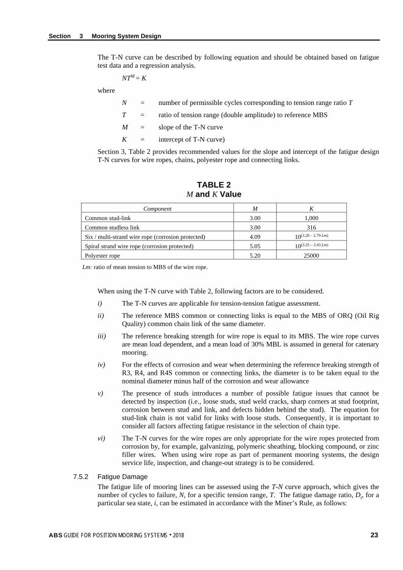
Section 3 Mooring System Design
The T-N curve can be described by following equation and should be obtained based on fatigue test data and a regression analysis.
NTM = K
where
N = number of permissible cycles corresponding to tension range ratio T
T = ratio of tension range (double amplitude) to reference MBS
M = slope of the T-N curve
K = intercept of T-N curve)
Section 3, Table 2 provides recommended values for the slope and intercept of the fatigue design T-N curves for wire ropes, chains, polyester rope and connecting links.
TABLE 2 M and K Value
Component M K Common stud-link 3.00 1,000 Common studless link 3.00 316 Six / multi-strand wire rope (corrosion protected) 4.09 10(3.20 – 2.79 Lm) Spiral strand wire rope (corrosion protected) 5.05 10(3.25 – 3.43 Lm) Polyester rope 5.20 25000
Lm: ratio of mean tension to MBS of the wire rope.
When using the T-N curve with Table 2, following factors are to be considered.
i) The T-N curves are applicable for tension-tension fatigue assessment.
ii) The reference MBS common or connecting links is equal to the MBS of ORQ (Oil Rig Quality) common chain link of the same diameter.
iii) The reference breaking strength for wire rope is equal to its MBS. The wire rope curves are mean load dependent, and a mean load of 30% MBL is assumed in general for catenary mooring.
iv) For the effects of corrosion and wear when determining the reference breaking strength of R3, R4, and R4S common or connecting links, the diameter is to be taken equal to the nominal diameter minus half of the corrosion and wear allowance
v) The presence of studs introduces a number of possible fatigue issues that cannot be detected by inspection (i.e., loose studs, stud weld cracks, sharp corners at stud footprint, corrosion between stud and link, and defects hidden behind the stud). The equation for stud-link chain is not valid for links with loose studs. Consequently, it is important to consider all factors affecting fatigue resistance in the selection of chain type.
vi) The T-N curves for the wire ropes are only appropriate for the wire ropes protected from corrosion by, for example, galvanizing, polymeric sheathing, blocking compound, or zinc filler wires. When using wire rope as part of permanent mooring systems, the design service life, inspection, and change-out strategy is to be considered.
7.5.2 Fatigue Damage The fatigue life of mooring lines can be assessed using the T-N curve approach, which gives the number of cycles to failure, N, for a specific tension range, T. The fatigue damage ratio, Di, for a particular sea state, i, can be estimated in accordance with the Miner’s Rule, as follows:
ABS GUIDE FOR POSITION MOORING SYSTEMS . 2018 23

Section 3 Mooring System Design
Di = i
i
Nn
where
ni = number of cycles within the tension range interval for a given sea state i.
Ni = number of cycles to failure at tension range as given by the appropriate T-N curve.
The cumulative fatigue damage, D, for all of the expected number of sea states NN (identified in a wave scatter diagram), is to be calculated as follows:
D = ∑=
NN
iiD
1
DT * SF ≤ 1.0
where
DT = total accumulated damage from all anticipated sources over the life cycle of the station keeping system
= D L + any fatigue damage arising from other sources
D = annual fatigue damage calculated, years–1
L = design service life, in years
SF = fatigue safety factor
The detailed analysis procedures for the tension ranges are provided in Section 8 of this Guide.
7.5.3 Bending Tension Fatigue Combined bending-tension of wire ropes and chains generally occurs at locations such as fairleads, bending shoes, chain stoppers, hawser pipes, bend-limiting devices, and adjacent to clump weights and mid-water buoys. At these locations, tension-tension fatigue damage is aggravated by the presence of bending. Bending effects on wire rope and chain fatigue are to be considered in connection with the following conditions:
i) Wire rope that passes over pulleys or fairleads
ii) Chain that experiences in-plane bending (IPB) and out-of-plane bending (OPB) due to constrained interlink rotation under tension, such as chains on a chain wheel (fairlead), in a chain hawser pipe, or at a chain stopper
Free bending at wire rope terminations can induce significant fatigue damage and reduce fatigue life. Bend-limiting devices should be incorporated at such locations. Such devices should be designed to smoothly transfer forces from the termination to the rope over the full range of structure draft and offset conditions.
Sheaves used in position mooring system are to be provided with sheave to rope diameter ratio of 40-60 to minimize tension-bending fatigue.
Where applicable, out-of-plane bending, in-plane bending, and tension-tension (OPB/IPB/TT) are to be considered in the fatigue damage assessment. Various methods, including finite element analysis method and chain testing, may be used to determine the bending moments and stresses of the subject chain links. Appendix 3 provides guidelines for the assessment method of bending-tension fatigue including OPB/IPB/TT.
In the absence of suitable data on the fatigue damage due to OPB and IPB, a load factor of 1.15 can be used in the fatigue analysis to take into account the bending effect of chain links.
24 ABS GUIDE FOR POSITION MOORING SYSTEMS . 2018
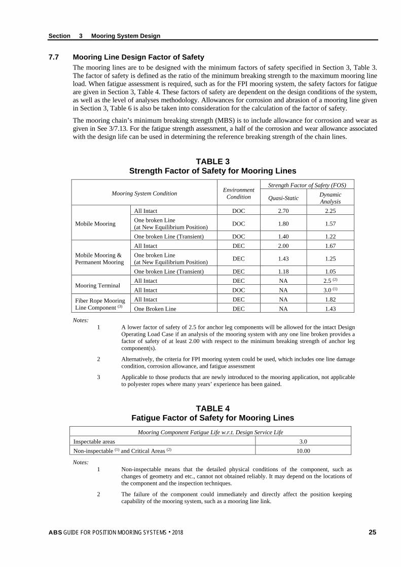
Section 3 Mooring System Design
7.7 Mooring Line Design Factor of Safety The mooring lines are to be designed with the minimum factors of safety specified in Section 3, Table 3. The factor of safety is defined as the ratio of the minimum breaking strength to the maximum mooring line load. When fatigue assessment is required, such as for the FPI mooring system, the safety factors for fatigue are given in Section 3, Table 4. These factors of safety are dependent on the design conditions of the system, as well as the level of analyses methodology. Allowances for corrosion and abrasion of a mooring line given in Section 3, Table 6 is also be taken into consideration for the calculation of the factor of safety.
The mooring chain’s minimum breaking strength (MBS) is to include allowance for corrosion and wear as given in See 3/7.13. For the fatigue strength assessment, a half of the corrosion and wear allowance associated with the design life can be used in determining the reference breaking strength of the chain lines.
TABLE 3 Strength Factor of Safety for Mooring Lines
Mooring System Condition Environment Condition
Strength Factor of Safety (FOS)
Quasi-Static Dynamic Analysis
Mobile Mooring
All Intact DOC 2.70 2.25 One broken Line (at New Equilibrium Position) DOC 1.80 1.57
One broken Line (Transient) DOC 1.40 1.22
Mobile Mooring & Permanent Mooring
All Intact DEC 2.00 1.67 One broken Line (at New Equilibrium Position) DEC 1.43 1.25
One broken Line (Transient) DEC 1.18 1.05
Mooring Terminal All Intact DEC NA 2.5 (2) All Intact DOC NA 3.0 (1)
Fiber Rope Mooring Line Component (3)
All Intact DEC NA 1.82 One Broken Line DEC NA 1.43
Notes: 1 A lower factor of safety of 2.5 for anchor leg components will be allowed for the intact Design
Operating Load Case if an analysis of the mooring system with any one line broken provides a factor of safety of at least 2.00 with respect to the minimum breaking strength of anchor leg component(s).
2 Alternatively, the criteria for FPI mooring system could be used, which includes one line damage condition, corrosion allowance, and fatigue assessment
3 Applicable to those products that are newly introduced to the mooring application, not applicable to polyester ropes where many years’ experience has been gained.
TABLE 4 Fatigue Factor of Safety for Mooring Lines
Mooring Component Fatigue Life w.r.t. Design Service Life Inspectable areas 3.0 Non-inspectable (1) and Critical Areas (2) 10.00
Notes: 1 Non-inspectable means that the detailed physical conditions of the component, such as
changes of geometry and etc., cannot not obtained reliably. It may depend on the locations of the component and the inspection techniques.
2 The failure of the component could immediately and directly affect the position keeping capability of the mooring system, such as a mooring line link.
ABS GUIDE FOR POSITION MOORING SYSTEMS . 2018 25

Section 3 Mooring System Design
7.9 Mooring Anchor 7.9.1 Anchor Holding Capacity
The anchoring system includes drag anchors, pile anchors, plate anchors, suction piles and dynamically installed piles. In general, they can be categorized as anchors that have vertical load capacity and that have no or very limited vertical load capacity. The holding capacity of an anchor in a particular soil condition represents the maximum pull-out force that can be resisted by the anchor. Empirical method, limit equilibrium method, plastic limit analysis method or advanced numerical method may be used to predict the anchor behavior in soft to medium stiff clay. However, all the methods need to be calibrated against well controlled and instrumented anchor test data. The type and design of anchors are to be submitted for review, together with the documentation for estimating their holding capacity in various types of soil. Section 6 of this Guide provides details on the anchors of different types.
7.9.2 Factor of Safety of Anchor Holding Capacity for Permanent Mooring Systems The factor of safety for anchors is defined as anchor holding capacity divided by maximum anchor load from mooring dynamic analysis. Section 3, Table 5 provides the factors of safety for drag anchors, plate anchors, suction piles, pile anchors, and dynamically installed piles.
TABLE 5 Factor of Safety for Anchor Holding Capacity
Factor of Safety
Drag Anchors All Intact (DEC) 1.50 One Broken Line (DEC) 1.00
Plate Anchors and Dynamically Installed Piles All Intact (DEC) 2.00 One Broken Line (DEC) 1.50
Suction Piles, Driven Pile Anchor and Gravity Anchors All Intact-Lateral (DEC) 1.6 All Intact-Axial (DEC) 2.0 One Broken Line-Lateral (DEC) 1.2 One Broken Line-Axial (DEC) 1.5
The following method can be used for lateral/axial or combined factor of safety:
If θ ≤ θlateral FOS = FOSlateral
If θ ≥ θaxial FOS = FOSaxial
If θlateral ≤ θ ≤ θaxial FOS = FOSlateral + lateralaxial
lateral
θ−θθ−θ * (FOSaxial – FOSlateral)
where
FOS = factor of safety (FOS)
FOSlateral = lateral FOS from Section 3, Table 5
FOSaxial = axial FOS from Section 3, Table 5
θ = angle of mooring line from horizontal at anchor attachment point
26 ABS GUIDE FOR POSITION MOORING SYSTEMS . 2018

Section 3 Mooring System Design
θlateral = load angle, measured from horizontal, below which the ultimate capacity is controlled by the lateral capacity. The lateral capacity is defined as the capacity under purely horizontal loads
θaxial = load angle, measured from horizontal, above which the ultimate capacity is controlled by the axial capacity. The axial capacity is defined as the capacity under purely vertical loads.
θaxial and θlateral could be obtained from either numerical simulations or laboratory tests. If the information is missing for θaxial and θlateral, FOSaxial is to be used for a conservative design.
7.9.3 Factor of Safety of Anchor Holding Capacity for Mooring Terminals If a Vertically Loaded Anchor (VLA) is used, the factor of safety given in Section 3, Table 5 is to be applied.
For mooring systems with drag anchors, the required minimum factors of safety given below are to be used.
• 2.0 For the Design Operating Load Case, mooring system intact
• 1.5 For the Design Environmental Load Case, mooring system intact
• 1.60 For the Design Operating Load Case, mooring system one-line damage
7.9.4 Drag Anchor Uplift For drag anchors, the mooring line length should in general be sufficient to prevent anchor uplift under the design environmental condition. This requirement is especially important for anchors in sand and hard soil where anchor penetration is shallow. For soft clay conditions, a small angle for the damaged case with one broken line may be considered by ABS on a case-by-case basis.
Uplift of drag anchors may be permitted if it can be demonstrated that the anchor has sufficient vertical resistance for the soil condition under consideration.
For mobile mooring, only steady wind, wave and current forces need be applied in evaluating anchor uplift forces.
7.11 Mooring between Vessel and Installation/ Mooring Terminal When hawsers are used as the connecting links, they are to be designed using the following factors of safety on the breaking strength of the weakest part. The strength of ropes or hawsers is to be determined in accordance with, and certified to, the latest version of OCIMF Prototype Rope Testing. The breaking strength of spliced rope is to be established by appropriate testing. The breaking strength of the hawser is to be the lower value of the hawser in wet or dry condition.
• With one fairlead: F.S. = 1.67
• With multiple fairleads: F.S. = 2.50
Where the vessel is moored to the installation or mooring terminal using hawsers running through more than two (2) fairleads on the vessel, the hawser loads are to be calculated as if there are only two (2) fairleads.
The hawser manufacturer is to comply with the OCIMF Quality Control and Inspection during the Production of Hawsers. Note: The above mentioned OCIMF references are available in the volume entitled, OCIMF Guidelines for the
Purchasing and Testing of SPM Hawsers.
When a rigid mooring structure is used as the mooring structure between the vessel and the installation, the connecting structures are to comply with 3-2-4/5 of the ABS MODU Rules.
ABS GUIDE FOR POSITION MOORING SYSTEMS . 2018 27
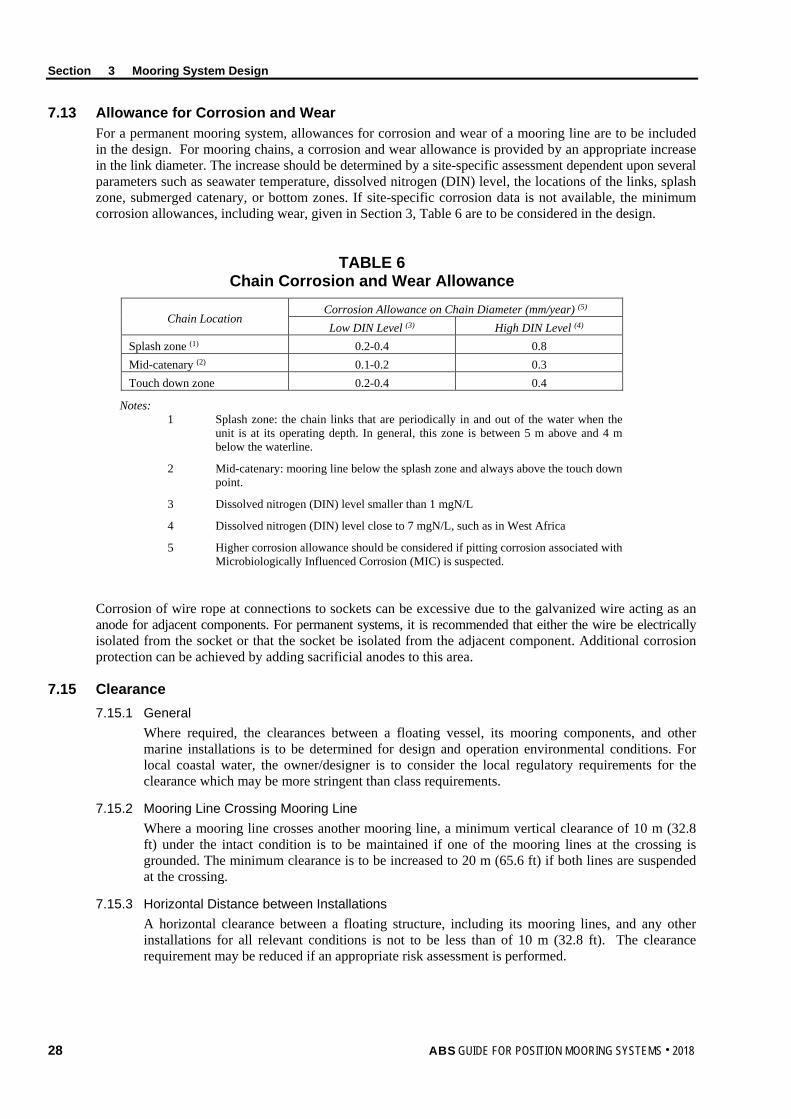
Section 3 Mooring System Design
7.13 Allowance for Corrosion and Wear For a permanent mooring system, allowances for corrosion and wear of a mooring line are to be included in the design. For mooring chains, a corrosion and wear allowance is provided by an appropriate increase in the link diameter. The increase should be determined by a site-specific assessment dependent upon several parameters such as seawater temperature, dissolved nitrogen (DIN) level, the locations of the links, splash zone, submerged catenary, or bottom zones. If site-specific corrosion data is not available, the minimum corrosion allowances, including wear, given in Section 3, Table 6 are to be considered in the design.
TABLE 6 Chain Corrosion and Wear Allowance
Chain Location Corrosion Allowance on Chain Diameter (mm/year) (5) Low DIN Level (3) High DIN Level (4)
Splash zone (1) 0.2-0.4 0.8 Mid-catenary (2) 0.1-0.2 0.3 Touch down zone 0.2-0.4 0.4
Notes: 1 Splash zone: the chain links that are periodically in and out of the water when the
unit is at its operating depth. In general, this zone is between 5 m above and 4 m below the waterline.
2 Mid-catenary: mooring line below the splash zone and always above the touch down point.
3 Dissolved nitrogen (DIN) level smaller than 1 mgN/L
4 Dissolved nitrogen (DIN) level close to 7 mgN/L, such as in West Africa
5 Higher corrosion allowance should be considered if pitting corrosion associated with Microbiologically Influenced Corrosion (MIC) is suspected.
Corrosion of wire rope at connections to sockets can be excessive due to the galvanized wire acting as an anode for adjacent components. For permanent systems, it is recommended that either the wire be electrically isolated from the socket or that the socket be isolated from the adjacent component. Additional corrosion protection can be achieved by adding sacrificial anodes to this area.
7.15 Clearance 7.15.1 General
Where required, the clearances between a floating vessel, its mooring components, and other marine installations is to be determined for design and operation environmental conditions. For local coastal water, the owner/designer is to consider the local regulatory requirements for the clearance which may be more stringent than class requirements.
7.15.2 Mooring Line Crossing Mooring Line Where a mooring line crosses another mooring line, a minimum vertical clearance of 10 m (32.8 ft) under the intact condition is to be maintained if one of the mooring lines at the crossing is grounded. The minimum clearance is to be increased to 20 m (65.6 ft) if both lines are suspended at the crossing.
7.15.3 Horizontal Distance between Installations A horizontal clearance between a floating structure, including its mooring lines, and any other installations for all relevant conditions is not to be less than of 10 m (32.8 ft). The clearance requirement may be reduced if an appropriate risk assessment is performed.
28 ABS GUIDE FOR POSITION MOORING SYSTEMS . 2018

Section 3 Mooring System Design
7.15.3 Clearance between a Drag Anchor and Other Installations If an installation lies in the dragging path between the anchor and the floating unit, the final anchor position is to allow at least 300 m drag before contacting the installation. Otherwise the anchor is to be at least 100 m from the marine installation. Anchors are not allowed to drag over pipelines or other critical subsea infrastructures in general.
9 Mooring Line Monitoring
9.1 Mooring Line Failure Detection Where required, the design of the mooring system is to include suitable arrangements and/or equipment for the crew to periodically verify that each mooring leg remains intact. Suitable arrangements might include, but are not necessarily limited to, mooring line load monitoring arrangements, inclinometers, laser measuring devices, excursion monitoring systems (GPS), and submersible cameras. Noting that these arrangements will have to operate for the life of the vessel, the design should take into account:
i) Robustness and reliability
ii) Serviceability and maintainability
iii) Validation and periodic verification/testing
Such systems are not required to constantly monitor or detect mooring line failures, nor is it a requirement that they should alarm on the failure of a mooring leg. However, as a minimum, there should be adequate procedural arrangements in place for the crew to periodically check the integrity of the lines. Note: Mooring legs can be visually checked on certain types/designs of mooring systems. For example, mooring lines on
External Turret and some Spread Moored designs can be visually observed and checked without the need for any additional equipment. Where this is not possible, the design is to include such equipment and systems as may be necessary so that the crew can periodically verify that all of the mooring lines remain intact.
9.3 Mooring Line Tension Monitoring for MODUs Means are to be provided at the individual winch or windlass control positions to monitor anchor line tension, winch or windlass power load and to indicate the amount of anchor line paid out.
9.5 Heading Monitoring of Moored Units For a mooring system where the heading of the moored floating structures/units is critical in terms of load on mooring systems and operations of the installations, such as single point or turret mooring system, means to monitor the heading is to be provided.
ABS GUIDE FOR POSITION MOORING SYSTEMS . 2018 29
S e c t i o n 4 : T h r u s t e r - A s s i s t e d M o o r i n g
S E C T I O N 4 Thruster-Assisted Mooring
1 Introduction
1.1 General Thrusters may be used to assist the mooring system by reducing the mean environmental forces, controlling the floating unit’s heading, or a combination of the two. Thruster-assisted mooring (TAM) systems can be broadly categorized into manual and automatic thruster-assisted mooring systems (TAMs), depending on the type of thrust assist (TA) system fitted on the unit.
1.3 Application This Section applies to mobile offshore units (MOUs) and mobile offshore drilling units (MODUs) operating with TAM systems for the optional notations of: TAM (Automatic thruster control system), TAM-R (Automatic thruster control system with redundancy), and TAM (Manual) (Manual thruster control system). At the request of the Owners, the TAM system may be verified for compliance with the provisions of this Section with the appropriate class notation assigned.
3 Technical Requirements
3.1 Thruster-Assisted Mooring Design Criteria 3.1.1 Environment Condition
For a thruster-assisted mooring MOU or MODU, the design environmental conditions are to be specified by the owner. Under the specified environmental conditions, the MOU or MODU is to be capable to maintain the position and heading, and the mooring lines to maintain the required factors of safety given in Section 4, Table 3.
3.1.2 System Design Conditions The design of a thruster-assisted mooring system is to consider the intact and damaged condition of the system. Section 4, Table 1 provides the conditions to be analyzed, and the mooring lines are to meet the factors of safety given in Section 4, Table 3.
TABLE 1 Intact and Damaged TAM Definitions
TAM Mooring System TA System Intact Intact Intact
Damaged Intact Damaged (2) Damaged Damaged (1) Intact
Notes: 1 loss of a single mooring line
2 loss of a single thruster or loss of more than one thruster determined based on FMEA study.
30 ABS GUIDE FOR POSITION MOORING SYSTEMS . 2018
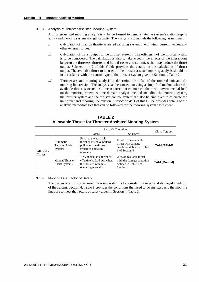
Section 4 Thruster-Assisted Mooring
3.1.3 Analysis of Thruster-Assisted Mooring System A thruster-assisted mooring analysis is to be performed to demonstrate the system’s stationkeeping ability and mooring system strength capacity. The analysis is to include the following, as minimum:
i) Calculation of load on thruster-assisted mooring system due to wind, current, waves, and other external forces.
ii) Calculation of thrust output of the thruster systems. The efficiency of the thruster system is to be considered. The calculation is also to take account the effects of the interactions between the thrusters, thruster and hull, thruster and current, which may reduce the thrust output. Subsection 4/9 of this Guide provides the details on the calculation of thrust output. The available thrust to be used in the thruster assisted mooring analysis should be in accordance with the control type of the thruster system given in Section 4, Table 2.
iii) Thruster-assisted mooring analysis to determine the offset of the moored unit and the mooring line tension. The analysis can be carried out using a simplified method where the available thrust is treated as a mean force that counteracts the mean environmental load on the mooring system. A time domain analysis method including the mooring system, the thruster system and the thruster control system can also be employed to calculate the unit offset and mooring line tension. Subsection 4/11 of this Guide provides details of the analysis methodologies that can be followed for the mooring system assessment.
TABLE 2 Allowable Thrust for Thruster Assisted Mooring System
Analysis Condition Class Notation
Intact Damaged
Allowable Thrust
Automatic Thruster Assist Systems
Equal to the available thrust or effective bollard pull when the thruster system is operating normally
Equal to the available thrust with damage condition defined in Table 1 of Section 4
TAM, TAM-R
Manual Thruster Assist Systems
70% of available thrust or effective bollard pull when the thruster system is operating normally
70% of available thrust with the damage condition defined in Table 1 of Section 4
TAM (Manual)
3.1.4 Mooring Line Factor of Safety The design of a thruster-assisted mooring system is to consider the intact and damaged condition of the system. Section 4, Table 1 provides the conditions that need to be analyzed and the mooring lines are to meet the factors of safety given in Section 4, Table 3.
ABS GUIDE FOR POSITION MOORING SYSTEMS . 2018 31
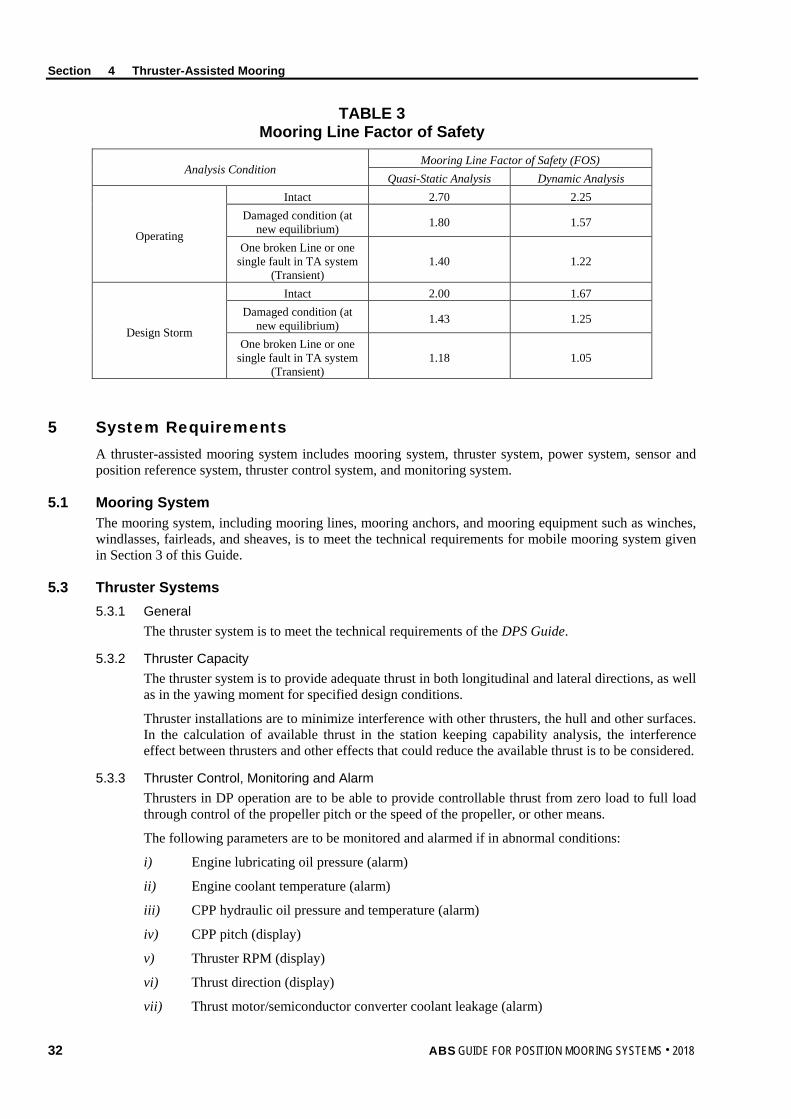
Section 4 Thruster-Assisted Mooring
TABLE 3 Mooring Line Factor of Safety
Analysis Condition Mooring Line Factor of Safety (FOS)
Quasi-Static Analysis Dynamic Analysis
Operating
Intact 2.70 2.25 Damaged condition (at
new equilibrium) 1.80 1.57
One broken Line or one single fault in TA system
(Transient) 1.40 1.22
Design Storm
Intact 2.00 1.67 Damaged condition (at
new equilibrium) 1.43 1.25
One broken Line or one single fault in TA system
(Transient) 1.18 1.05
5 System Requirements A thruster-assisted mooring system includes mooring system, thruster system, power system, sensor and position reference system, thruster control system, and monitoring system.
5.1 Mooring System The mooring system, including mooring lines, mooring anchors, and mooring equipment such as winches, windlasses, fairleads, and sheaves, is to meet the technical requirements for mobile mooring system given in Section 3 of this Guide.
5.3 Thruster Systems 5.3.1 General
The thruster system is to meet the technical requirements of the DPS Guide.
5.3.2 Thruster Capacity The thruster system is to provide adequate thrust in both longitudinal and lateral directions, as well as in the yawing moment for specified design conditions.
Thruster installations are to minimize interference with other thrusters, the hull and other surfaces. In the calculation of available thrust in the station keeping capability analysis, the interference effect between thrusters and other effects that could reduce the available thrust is to be considered.
5.3.3 Thruster Control, Monitoring and Alarm Thrusters in DP operation are to be able to provide controllable thrust from zero load to full load through control of the propeller pitch or the speed of the propeller, or other means.
The following parameters are to be monitored and alarmed if in abnormal conditions:
i) Engine lubricating oil pressure (alarm)
ii) Engine coolant temperature (alarm)
iii) CPP hydraulic oil pressure and temperature (alarm)
iv) CPP pitch (display)
v) Thruster RPM (display)
vi) Thrust direction (display)
vii) Thrust motor/semiconductor converter coolant leakage (alarm)
32 ABS GUIDE FOR POSITION MOORING SYSTEMS . 2018

Section 4 Thruster-Assisted Mooring
viii) Thrust motor semiconductor converter temperature (display)
ix) Thruster motor exciter power available (display)
x) Thruster motor supply power available (display)
xi) Thruster motor overload (alarm)
xii) Thruster motor high temperature (alarm)
5.5 Power Systems In general, the requirements found in in Part 4, Chapter 8 of the Rules for Building and Classing Steel Vessels (Steel Vessel Rules) are to be complied with, as applicable.
For TAM notation, an independent uninterruptible power system (UPS) is to be provided for each independent control system and its associated monitoring and reference system. Each uninterruptible power system is to be capable of supplying power for a minimum 30 minutes after failure of the main power supply.
5.7 Control and Monitoring System 5.7.1 General
The control and monitoring system is to be in accordance with technical requirements of the DPS Guide where applicable.
5.7.2 Control Stations Control Station Arrangement. The main TA control station is to be so arranged that the operator is made aware of the external environmental conditions and any activities relevant to the TA operation.
Emergency Shutdown. An emergency shutdown facility for each thruster is to be provided at the main TA control station. The emergency shutdown facility is to be independent of the automatic control systems, manual position control system and manual thruster control system. The emergency shutdown facility is to be arranged to shut down each thruster individually.
5.7.3 Manual Thruster Control System For a floating unit with a TAM (Manual) notation, a manual thruster control system is to be provided. The manual thruster control system is to be able to effectively control the thruster from the navigation bridge. Control power is to be from the thruster motor controller or directly from the main switchboard. The manual thruster control system is to be independent so that it will be operational if the other control systems fail. The system is to provide an individual manual level for each thruster. A joystick system with manual control of the unit position and automatic heading control is to be provided.
5.7.4 Automatic Thruster Control System For a floating unit with a TAM notation, an automatic control system and a manual thruster control system with automatic heading control are to be provided. Transfer of control between the two systems is to be initiated manually.
For a floating unit with a TAM-R notation, the redundancy of the control system, based on the FMEA study with a single fault of a component or a system, is to be provided.
5.7.5 Environment Sensor and Position Reference System Position reference systems, wind sensors and gyro-compass are to be fitted and they are to be in accordance with technical requirements of the DPS Guide.
For a floating unit with a TAM-R notation, the sensors, gyro-compass and position reference systems are to be provided in redundancy based on the FMEA study with a single fault of a component or a system.
ABS GUIDE FOR POSITION MOORING SYSTEMS . 2018 33
Section 4 Thruster-Assisted Mooring
5.7.6 Mooring Line Tension For a floating unit with a TAM or TAM-R notation, mooring line tension is to be included in the automatic thruster control system either through a mathematical model where the line tension can be derived from the position of the units or other parameters, or direct line tension measurement. Care is to be taken on the quality of the mooring line tension inputs to the control system. Calibration of the mooring system model and filter for the measurement data is to be demonstrated, where applicable.
5.7.7 Other External Forces If other equipment exerts external forces that can affect the vessel positioning such as risers, pipe tensioners, hawser tension, or others, then a careful system engineering approach is to be implemented for automatic or manual feed forward compensation.
5.7.8 Monitoring Monitoring of position references and sensors is to be in accordance with technical requirements of the DPS Guide where applicable.
For a thruster-assisted mooring system, mooring line tensions are to be monitored and an alarm is to be initiated if the mooring line tension is out of design range.
5.9 Communications for Units with Thrust Assist Mooring System One means of voice communication is to be provided between each thruster control position and the navigation bridge, the engine control position, main propulsion control station, the thruster room or any relevant operation control centers associated with thruster-assisted mooring system.
7 Failure Mode and Effect Analysis For a unit with a TAM-R notation, where the redundancy of the thruster assisting system is required, the redundancy is to be demonstrated by Failure Mode and Effect Analysis (FMEA) and associated FMEA testing.
The failure modes to be considered include the failure of any active components, subsystems and systems. More detailed guidelines on FMEA can be found in the ABS DPS Guide, IMCA M 166, IMCA M 178, IEC 60812, and MTS DP Vessel Design Philosophy Guideline.
The objectives of the FMEA study should, at a minimum, include:
• Identification and provision of recommendations to eliminate or mitigate the effects of all single faults and common mode failures in the thruster assisting system which, if any occurs, would cause total or partial loss of thruster assisting capability.
• Demonstration of effective redundancy of the systems.
• Recommendation of FMEA tests.
The FMEA and the FMEA test programs are to be maintained onboard, and are to be updated to address subsequent modifications to the thruster assisting system hardware or software.
9 Available Thrust
9.1 Available Thrust for Thrusters Manufacturer’s test data of full scale or suitable model tests for the thrust output of thrusters are to be used in general. The assessment of available thrust is typically indicated as thrust at full rated power. The availability of full power is a function of the prime mover characteristic. The power/torque/rpm characteristic for diesel driven thrusters is to be evaluated to determine the level of power available during thruster operations.
For thrusters with controllable pitch propellers as well as with hydraulically driven prime movers, full power is to be available at any inflow velocity.
34 ABS GUIDE FOR POSITION MOORING SYSTEMS . 2018
Section 4 Thruster-Assisted Mooring
Electric drives typically have a certain RPM range in which full power is available. The thruster propeller is to be selected so that thruster operations fall within this range.
If no test results are available for the thrust output of the thrusters, Appendix 1 of this Guide provides the guidelines for determining available thrust, which addresses typical thrusters and installation. Those guidelines may be used for preliminary studies.
9.3 Thruster-Thruster Interaction When one thruster operates downstream of another, the available thrust of the thruster is reduced due to thrusters interaction. The effect of the interaction depends on the following
i) Distance between the thrusters
ii) Azimuth of the thrusters
iii) Diameter of the thruster propeller
iv) Thruster load
v) Thruster design/configuration (i.e., degree of tilt of the propeller and/or nozzle axis)
This interaction effect is to be included in the available thrust assessment. The results from full scale or suitable model test for the thrust-thrust interaction effect are to be used whenever possible. If no such results are available, Appendix 1 of this Guide can be used as guidelines for the assessment of the interaction effect on the available thrust.
9.5 Thruster-Hull Interaction The interaction between thrusters and the hull also reduces available thrust of the thrusters. The interaction includes following factors; they are to be included in the station keeping performance analysis:
i) Friction. The flow of the slipstream along the hull will result in the thrust degradation due the friction of the hull. The degradation is related to the length and breadth of the flow along the hull.
ii) Coanda Effect. When a thruster is oriented in a transverse direction, the output thrust of the thruster is affected by the Coanda effect. The reduction of the thrust is related to the bilge radius and the length of the flow underneath the hull.
iii) Pontoon Blockage. The blockage of the slipstream due to presence of the pontoon, such as when a slipstream is orientated toward the pontoon, will affect the thrust output of the thruster. The effect is related to the distance between the pontoons and the azimuth of the thruster.
iv) Tilted Thruster/Nozzle. A tilted thruster/nozzle can reduce thruster-hull interactions and thus increase the output of the thrusters. This improvement can be considered in the available thrust calculation.
The full scale or model test results for the effects of thruster-hull interactions mentioned above and the tilted thruster/nozzle are to be used whenever possible. If such results are not available, Appendix 1 of this Guide can be used as a guideline for the assessment of the interaction effect on the available thrust.
9.7 Thruster-Current Interaction Current inflow could reduce the thrust output of the thrusters and the thrust reduction is to be included in the station keeping performance analysis. The manufacturer’s test data of full scale or a suitable model test for the current effect is to be used whenever possible. If such data is not available, Appendix 1 of this Guide can be used as a guideline for the assessment of the current effect.
ABS GUIDE FOR POSITION MOORING SYSTEMS . 2018 35

Section 4 Thruster-Assisted Mooring
11 Thruster Assisted Mooring Analysis Methodology
11.1 Mean Load Reduction The mean load reduction method is a simplified means of accounting for the contribution from thrusters by reducing the mean environmental loads in the surge, sway, and yaw directions. It could include:
i) Calculation of the available thrusts from thrusters according the Subsection 4/9 of this Guide for all directions.
ii) If the thruster system is not designed to provide heading control of the moored units, such as those used in a spread mooring system where the vessel heading is held stable by the mooring lines, the available thrust at the equilibrium position (heading), can be subtracted from the environmental mean load. The mooring analysis can then be carried out following the procedures given in Section 8 of this Guide.
iii) If the thruster system is designed to provide heading control of the moored unit, such as those used in a turret mooring system, the available thrust is to be evaluated for the heading control capability first. Once the thruster capability for vessel’s heading control is demonstrated, additional available thrust can be subtracted from the mean environmental load.
11.3 Time Domain Analysis Approach A thruster-assisted mooring system is a feedback system. Section 4, Figure 1 depicts a typical automatic thruster control feedback loop. The feed-in information includes environmental load, vessel’s current position and required position. The time domain analysis calculates the vessel’s motion, mooring line load and determines the required thruster power to keep the unit at the required position.
In this analysis, constant wind, current, steady wave drift forces, and the slowly varying wave drift forces are typically included. Wave frequency wave forces, which are not countered by the thruster system, can be excluded in the simulation. The wave frequency motions can be computed separately using a vessel motion program and added to the output from the time domain simulator.
FIGURE 1 Automatic Thruster Control Feedback Loop
Required Position
EKF
Measured Position VESSEL THRUST
PID ALLOC
Wind Feed Forward
Wind, Waves, Current Mooring Load
36 ABS GUIDE FOR POSITION MOORING SYSTEMS . 2018
ABS GUIDE FOR POSITION MOORING SYSTEMS . 2018 37
S e c t i o n 5 : P r e - l a i d S t a t i o n k e e p i n g S y s t e m s f o r M o b i l e O f f s h o r e U n i t s
S E C T I O N 5 Pre-laid Stationkeeping Systems for Mobile Offshore Units
1 Introduction
1.1 General This Section provides technical requirements for a stationkeeping system of a MODU or a MOU with the following optional classification notations:
(P-PL): Position (pre-laid) mooring systems
(M-PL): Position (pre-laid) mooring equipment
TAM-PL: Pre-laid mooring system with automatic position control system
TAM-PL (Manual): Pre-laid mooring system with manual position control system
At the request of the Owners, the pre-laid stationkeeping systems may be verified for compliance with the requirements in this Section where applicable and the appropriate class notation can be assigned.
3 Technical Requirements
3.1 General The technical requirements are applicable to:
i) Mooring equipment, chain or wire rope carried onboard the unit
ii) Thruster control systems and their components
iii) Position keeping capability for the pre-laid stationkeeping system specified by the Owner
3.3 Class Notation (M-PL)
3.3.1 Equipment for Pre-laid Mooring
Where the optional ABS Notation (M-PL) is requested, the mooring equipment, anchors, chains, or wire ropes, which are onboard the unit and have been specified by the owner for the pre-laid position (pre-laid) mooring systems, have been tested in accordance with the specifications of the Owner and in the presence of a Surveyor.
3.5 Class Notation (P-PL)
3.5.1 Equipment for pre-laid mooring
Where the optional ABS Notation (P-PL) is requested, the on board equipment, anchors, chains or wire ropes onboard the unit are to meet following requirements:
The winches and windlasses are to comply with the requirements of 3-4-A1/5.1 of the MODU Rules.
Fairleads and sheaves are to be designed to prevent excessive bending and wear of the anchor lines.
The attachments to the hull or structure are to be capable of withstanding the stresses imposed when an anchor line is loaded to its rated breaking strength.
Section 5 Pre-laid Stationkeeping Systems for Mobile Offshore Units
38 ABS GUIDE FOR POSITION MOORING SYSTEMS . 2018
3.5.2 Pre-laid Mooring System
Where the optional ABS Notation (P-PL) is requested, the pre-laid mooring system is to comply with the requirements for mobile mooring system in Subsection 3/7 of this Guide. The mooring lines that are pre-laid are to have the design strength used in the mooring analysis.
The design holding power of the anchors and the information of pre-laid chains is to be submitted.
3.7 Class Notation TAM-PL (Manual) and TAM-PL
3.7.1 Equipment for Pre-laid Mooring System
Where the optional ABS Notation TAM-PL(Manual) or TAM-PL is requested, the pre-laid mooring system is to comply with the requirements in Subsection 5/3 of this Guide.
3.7.2 Thruster Assisting System
Where the optional ABS Notation TAM-PL(Manual) is requested, the thruster assisting system is to comply with the requirements for the thruster assisting system for Notation TAM (Manual) in Subsection 4/3 of this Guide.
Where the optional ABS Notation TAM-PL is requested, the thruster assisting system is to comply with the requirements for the thruster assisting system for Notation TAM in Subsection 4/3 of this Guide.
3.7.3 Thruster Assisted Pre-laid Mooring System
Where the optional ABS Notation TAM-PL(Manual) or TAM-PL is requested, the thruster-assisted pre-laid mooring system is to comply with the requirements in Section 4 and Section 5 of this Guide where applicable. The mooring lines that are pre-laid are to have the design strength used in the mooring analysis.
The design holding power of the anchors and the information of pre-laid chains are to be submitted.
5 Plans and Particulars to be Submitted
5.1 (P-PL) Notation For the (P-PL) symbol, the following plans are to be submitted to ABS:
Arrangement and complete details of the mooring components and equipment that are carried onboard the unit including their foundations and attachments to the unit
A sample mooring analysis describing the method of load calculations and analysis of dynamic systems to determine the mooring line design loads, assumed mooring system configuration including arrangement of pre-laid mooring components and accessories
Specifications and calculations for the mooring components and equipment that are carried onboard the unit
Operations Manual which clearly distinguishes the mooring components and equipment that are classed under ABS from pre-laid mooring components that are assumed at the offshore location

Section 5 Pre-laid Stationkeeping Systems for Mobile Offshore Units
5.3 TAM-PL and TAM-PL (Manual) Notations For the TAM-PL and TAM-PL (Manual) notations, the following plans and information are to be submitted to ABS:
• General arrangements of the thruster(s) installation, its location of installation, together with its supporting auxiliary machinery systems, fuel oil tanks, foundations, and watertight boundary fittings.
• The rated power/rpm and the rated thrust are to be indicated. For azimuthal thrusters, the mechanical and control systems for rotating the thruster assembly or for positioning the direction of thrust are to be submitted. Thruster specifications and calculations for thruster forces and power to counteract environmental forces are to be submitted. In addition, plans of each component and of the systems associated with the thruster are to be submitted. Arrangement and complete details of the mooring components and equipment that are carried onboard the unit including their foundations and attachments to the unit are to be provided.
• A sample mooring analysis describing method of load calculations and analysis of dynamic system to determine the mooring line design loads, assumed mooring system configuration including arrangement of pre-laid mooring components and accessories.
• Specifications and calculations for the mooring components and equipment that are carried onboard the unit.
• Operations Manual which clearly distinguish the mooring components and equipment that are classed under ABS from pre-laid mooring components that are assumed at the offshore location.
ABS GUIDE FOR POSITION MOORING SYSTEMS . 2018 39

S e c t i o n 6 : M o o r i n g S y s t e m C o m p o n e n t s
S E C T I O N 6 Mooring System Components
1 General The anchors, mooring lines, shackles and other associated connecting equipment should be designed, manufactured and tested in accordance with the published ABS requirements. In instances where ABS does not have published requirements, the equipment will be reviewed for compliance with applicable recognized industry standards.
Complete details and supporting calculations, including fatigue analysis where applicable, of the structural and mechanical components used in position mooring systems (e.g., connecting links, shackles, chain stoppers, fairleads, etc.), which transmit the mooring loads, are to be submitted.
All mooring system components such as anchors, anchor chains or wires, anchor chain accessories such as shackles or links, and anchor wire-rope accessories such as sockets or links, are to be manufactured and tested in the presence of and to the satisfaction of the Surveyor in accordance with approved plans. Section 6-1-10 of the MODU Rules provides more details on the requirements for equipment certification.
3 Mooring Lines Mooring line components such as wire rope, chain, connecting link, synthetic fiber rope and in-line buoys are to be designed that is compatible with the design conditions of the mooring system. For the mobile mooring systems, means are to be provided to enable the release of anchor lines from the unit upon loss of main power.
3.1 Mooring Wire Rope Mooring wire ropes and end sockets are to meet the material, design, manufacture, and testing requirements specified in industry recognized standard, such as API Spec 9A and RP 9B.
Wire rope manufacturers should provide users torque/twist data for the allowable tension range as part of the wire rope basic properties. Contact of wire rope in the dip or thrash zone may cause excessive wear in the rope/jacket or excessive free bending at the socket. This condition should be avoided for permanent moorings under normal operating environments
3.3 Synthetic Fiber Mooring Rope Requirements for synthetic fiber rope for mooring system can be found in the Fiber Rope Guidance Notes.
3.5 Mooring Chain and Accessories Mooring chain and accessories are to be manufactured according to the ABS Offshore Mooring Chain Guide. For buoyancy tanks, the requirements in ASME Boiler and Pressure Vessel Code can be used.
3.7 Other Components In general, the structural and mechanical components used in position mooring systems (e.g., connecting links, shackles, chain stoppers, fairleads, etc.), which transmit the mooring loads, are to be designed to the Minimum Breaking Strength (MBS) of the mooring line. The computed stress obtained from FE analysis is to be limited to minimum specified yield strength. Local stress due to large contact pressure obtained from FE analysis is to be limited to three times the minimum specified yield strength.
40 ABS GUIDE FOR POSITION MOORING SYSTEMS . 2018

Section 6 Mooring System Components
The fatigue life, where applicable, for inspectable and repairable structural and mechanical components used in position mooring systems is not to be less than 3 times the service life. For those that cannot be readily inspected and repaired, the fatigue life is to be at least 10 times the service life.
The attachments to the hull or structure are to be such as to withstand the stresses imposed when the mooring line is loaded the Minimum Breaking Strength (MBS) of the mooring line or maximum allowable mooring line load. Allowable stress is to comply with the Rules or Guide for the floating units to which the mooring system is attached.
5 Anchors Different types of foundation systems used for floating structures/units are drag anchors, pile anchors, vertically loaded anchors (VLAs) and suction piles. Gravity boxes, grouted piles, and templates may also be used and are considered to be within the scope of classification.
The type and design of anchors are to be submitted for review, together with documentation estimating their holding power in various types of soil.
The following is to be considered in the evaluation of the anchor holding capacity:
i) Cyclic, creep and soil set-up effects of the soil strength.
ii) Soil disturbance due to padeye and chain.
iii) If the reference site is within a seismic zone, potential of soil liquefaction and its impact.
iv) The effect of the inverse catenary line on the anchor loading directions is to be considered. An upper bound and a lower bound inverse catenary is be considered to establish the worst-case anchor loading.
Suitable anchor stowage arrangements are to be provided to prevent movement of the anchors during transit. When the unit is kept on position solely by DP units and the anchors are not used, anchors are not to be stored in the bolsters unless they are designed for the extreme design environmental conditions.
5.1 Drag Anchor Drag anchor holding capacity depends on the anchor type, as well as the condition of the anchor deployed in regard to penetration of the flukes, opening of the flukes, depth of burial, stability of the anchor during dragging, soil behavior of the flukes, etc. The designer is to submit to ABS the performance data for the specific anchor type and the site-specific soil conditions for the estimation of the ultimate holding capacity (UHC) of an anchor design. Because of the uncertainties and the wide variation of anchor characteristics, the actual holding capacity is to be determined after the anchor is deployed and test loaded.
The maximum load at anchor, Fanchor, is to be calculated, in consistent units, as follows:
Fanchor = Pline – WsubWD – Ffriction
Ffriction = fsLbedWsub
where
Pline = maximum mooring line tension
WD = water depth
fs = frictional coefficient of mooring line on sea bed at sliding
Lbed = length of mooring line on seabed at the design storm condition, not to exceed 20 percent of the total length of a mooring line
Wsub = submerged unit weight of mooring line
Note: The above equation for Fanchor is strictly correct only for a single line of constant, Wsub, without buoys or clump weights. Appropriate adjustments will be required for other cases.
ABS GUIDE FOR POSITION MOORING SYSTEMS . 2018 41

Section 6 Mooring System Components
The coefficient of friction fs depends on the soil condition and the type of mooring line. For soft mud, sand and clay, values of fs along with the coefficient of friction at start fst for wire rope and chain, provided in Section 6, Table 1, may be considered.
TABLE 1 Coefficient of Friction
Coefficient of Friction, f Starting (fst ) Sliding (fs )
Chain 1.00 0.70 Wire Rope 0.60 0.25
5.3 Driven Pile Anchor Driven pile anchors are capable of withstanding uplift and lateral forces at the same time. Analysis of the pile as a beam column on an elastic foundation is to be submitted to ABS for review. The analyses for different kinds of soil using representative soil resistance and deflection (p-y) curves are described in the ABS Offshore Installations Rules, API RP 2SK, API RP 2A and API RP 2T, as applicable. Where required, the fatigue analysis of the pile is to be submitted for review.
5.3.1 Allowable Yielding Stresses for Pile Anchors Where required, pile analysis in accordance with Section 3 of API RP 2A can be applied to the piles with diameter to thickness ratios (D/t) of less than 100. For cylindrical piles with D/t ratios exceeding 100, it is recommended that a detailed structural finite element model be developed for the global structural anchor analysis to verify that the anchor wall structure and appurtenances have adequate strength in highly loaded areas. Supplementary calculations may be necessary for members or appurtenances subjected to local loading.
The von Mises stress is to be limited to:
σeqv ≤ 0.9σyield for one line damage
σeqv ≤ 0.67σyield for intact
where
σyield = yield stress of the considered structural component, in kN/m2 (kgf/m2, lbf/ft2)
For highly localized stresses, the local yielding of the structure may be accepted provided it can be demonstrated that such yielding does not lead to progressive collapse of the overall structure and that the general structural stability is maintained.
It is recommended that pile foundations be designed to comply with the appropriate sections of API RP 2A. A pile driving record or pile grouting record is to be taken and submitted for each pile. The method of installation of the piles and the equipment employed is to be included in the pile driving record.
5.3.2 Fatigue Assessment of Pile Anchors Where required, the design fatigue life is to be at least 10 times of the intended service life. For driven pile anchors fatigue analysis is to be reviewed to evaluate the adequacy of the fatigue life considering both driving and in-place conditions. The critical locations, such as in way of padeye, girth welds, should be selected for the fatigue assessment based on the finite element results or calculated based on parametric equations taking into account fabrication tolerances. “In-Air” S-N curves may be used to calculate the pile driving fatigue damage, while in-place fatigue damage should be based on “Free Corrosion” S-N curves given in the ABS Guide for the Fatigue Assessment of Offshore Structures. Fatigue analyses of the suction piles should be carried out in accordance with the ABS Guide for the Fatigue Assessment of Offshore Structures using appropriate S-N curves provided in the Guide.
42 ABS GUIDE FOR POSITION MOORING SYSTEMS . 2018
Section 6 Mooring System Components
5.5 Plate Anchor Plate anchors can be used in a taut leg mooring system with approximately a 35 to 45 degree angle between the seabed and the mooring lines. These anchors are designed to withstand both the vertical and horizontal loads imposed by the mooring line.
Plate anchors can be drag embedded plate anchors or direct embedded plate anchors, according to different installation methods. Vertically Loaded Anchors (VLAs) are one type of plate anchors. It is important that the anchor’s penetration depth can be established during the installation process. After penetrating into the designated depth, a plate anchor gets its high ultimate pull-out capacity by having its fluke oriented nearly perpendicular to the applied load.
The structural and geotechnical holding capacity design of the plate anchors are to be submitted for review. This is to include the ultimate holding capacity and the anchor’s burial depth beneath the seabed. Additionally, the fatigue analysis of the anchor and the connectors joining the Plate anchors to the mooring line is to be submitted for review.
5.7 Suction Piles 5.7.1 General
Suction pile anchors are caisson foundations that are penetrated to the target depth by pumping out the water inside of the pile to create underpressure within the pile. They typically consist of a stiffened cylindrical shell with a cover plate at the top and an open bottom and they generally have larger diameters and are shorter in length than driven piles. These piles can be designed to have either a permanent or retrievable top depending on the required vertical holding capacity. The padeye for the mooring line connection can be at the top or at an intermediate level depending on the design of the suction pile.
Suction pile anchors are capable of withstanding uplift and lateral forces. Due to the geometry of the suction piles, the failure modes of the soils may be different than what are applicable for long, slender driven piles.
Geotechnical holding capacity and structural analyses for the suction piles are to be submitted to verify the adequacy of the suction piles to withstand the in-service and installation loads. Additionally, fatigue analysis of the suction piles are to be submitted to verify the adequacy of the fatigue life of the critical locations. The criteria given in 6/5.3.1 and 6/5.3.2 are applicable to suction piles.
Installation analyses are to be submitted to verify that the suction piles can be penetrated to the design penetration and that the suction piles can be retrieved, if necessary. It is suggested that a ratio of at least 1.5 between the force that would cause uplift of the soil-plug inside of the pile and the effective pile installation force be considered in the penetration analysis.
5.7.2 Stability Analysis of Suction Pile The buckling strength of the suction pile is to be checked in accordance with API Recommended Practice 2A, or the ABS Guide for Buckling and Ultimate Strength Assessment for Offshore Structures.
5.9 Dynamically Installed Piles Dynamically installed piles are finned piles designed to be released from height above the seabed and reach velocities of 20 to35 m/s (65 to 115 ft/s) at the seabed before self-embedment. They may be stabilized with multiple fins at the trailing edge.
The installation procedures of dynamically installed piles are to be submitted for ABS review and are to include all the necessary data for the Surveyor to inspect onboard, such as coordinates of piles installation, designed penetration depth, acceptable tolerances for pile position, actual penetration depth, inclination angle and azimuth.
Geotechnical holding capacity and structural analysis for the piles is to be submitted to verify the adequacy of the piles to withstand the in-service load. The geotechnical analysis and structural assessment may be performed in accordance with ABS Guidance Notes on Design and Installation of Dynamically Installed Piles. Fatigue assessment are to be submitted to demonstrate the adequacy of the mooring line attachment components for the expected service life of the mooring system. The criteria given in 6/5.3.1 and 6/5.3.2 are applicable to dynamically installed piles.
ABS GUIDE FOR POSITION MOORING SYSTEMS . 2018 43

Section 6 Mooring System Components
5.11 Gravity Anchors Where the anchoring system uses gravity boxes, resistance against sliding, uplifting, and overturning of the gravity boxes are to be analyzed. The forces due to environmental, gravity and mooring are to be taken into account appropriately. Scour effects on the gravity boxes are to be considered in the design.
7 Chain Stoppers The chain stoppers are to be so designed that no additional bending to the chain links is imposed and the links are evenly supported. Findings and recommendations from Chain Out of Plane Bending JIP can be used to minimize the OPB.
The strength analysis is to include the most unfavorable direction of the mooring line.
The chain stoppers are to be tested in accordance with the submitted specifications and to the satisfaction of the attending Surveyor.
Position mooring systems without chain stoppers will be specially considered.
9 Fairleads and Sheaves
Fairleads and sheaves are to be designed to prevent excessive bending and wear of the mooring lines. Sharp edges at the interface structures with the mooring line are to be avoided.
Sheaves used in position mooring system are to be provided with sheave to rope diameter ratio of 40-60 to minimize tension-bending fatigue. 7 to 9 pocket wildcat sheaves are recommended for chain. Other constructions which provide similar or better support may be considered.
The strength analysis is to include the most unfavorable direction of the mooring line.
Corrosion allowance or suitable cathodic protection is to be considered for underwater fairleads.
The fairleads are to be tested to the satisfaction of the attending Surveyor.
11 Winches and Windlasses The design of mooring winches and windlasses is to provide for adequate dynamic braking capacity to control normal combinations of loads from the anchor, anchor line and anchor handling vessel during the deployment of the anchors at the maximum design payout speed of the winch or windlass. Winch and windlass foundations and adjacent hull structures are to be designed to withstand an anchor line load at the winch or windlass at least equal to the rated breaking load of the anchor line.
For a winch intended for mooring line hook-up and future retensioning activities, the equipment is to be in compliance with recognized industry standards. The manufacturer needs to submit details to demonstrate compliance with the industry standards, either in the form of certificates issued by recognized certification bodies or by submitting details and calculations to ABS for review and approval.
Each winch or windlass is to be provided with two independent, power operated brakes and each brake is to be capable of holding a static load in the anchor line of at least 50 percent of the anchor line’s rated breaking strength. One of the brakes may be replaced by a manually operated brake.
On loss of power to the winches or windlasses, the power operated braking system is to be automatically applied and be capable of holding against 50 percent of the total static braking capacity of the windlass.
13 Quality Control Quality control details of the manufacturing process of the individual mooring system components are to be submitted. Components are to be designed, manufactured and tested in accordance with recognized standards insofar as possible and practical. Equipment so tested is to, insofar as practical, be legibly and permanently marked with the Surveyor’s stamp and delivered with documentation which records the results of the tests.
44 ABS GUIDE FOR POSITION MOORING SYSTEMS . 2018

Section 6 Mooring System Components
15 Control Station Where applicable, the control station is to include the following:
i) Means to indicate anchor line tensions and to indicate wind speed and direction.
ii) Reliable means to communicate between locations critical to the anchoring operation.
iii) Each winch or windlass is to be capable of being controlled from a position which provides a good view of the operation. Means are to be provided at the individual winch or windlass control positions to monitor anchor line tension, winch or windlass power load and to indicate the amount of anchor line paid out.
17 Single Point Mooring Systems This Subsection provides the requirements for the components that facilitate the weathervaning of the single point mooring systems, such as turrets and yokes, and which are not covered in mooring components, such as mooring lines and anchors.
For the onboard electrical installations related to the single point mooring systems, they are to comply with the requirements for the onboard electrical installations of moored structure/unit, such as FPI, MODUs, or others.
17.1 Design Loadings The design of structural and mechanical components is to consider the most adverse combination of loads, including, but not limited to, those listed below, and is to be submitted for review:
i) Dead Loads
ii) Dynamic Loads due to motions
iii) Mooring Loads
iv) Riser Loads
17.3 Structural Components In general, structural components are to be designed to a recognized code or standard. The structural and buoyancy elements of a single point mooring systems are to comply with the requirements of Rules and Guides for the floating units the mooring system is attached to.
17.5 Mechanical Components Mechanical components of an SPM usually include the Product Distribution Unit (PDU), bearings, driving mechanisms and various types of connectors. Where applicable, those components can be designed in accordance to the following standards and codes:
Product Distribution Unit ASME Boiler and Pressure Vessel Code AISC Steel Code ANSI B31.3 (for Pipe Swivels)
Bearings ABMA Codes (American Bearing Manufacturers Association ASME 77-DE-39
Connectors: driving mechanisms ASME Boiler and Pressure Vessel Code AISC Steel Code API Standards as applicable
Ancillary mechanical components, such as structural connectors, uni-joints, chain jacks, turret retrieval mechanisms, hoists, winches, and quick connect/disconnect devices are to be designed in accordance with applicable industry standards, codes, and published recommended practices.
ABS GUIDE FOR POSITION MOORING SYSTEMS . 2018 45
Section 6 Mooring System Components
17.7 Turret System A turret mooring system is one type of station keeping system for a floating installation and can either be installed internally or externally. Both internal and external turret mooring systems allow the installation to weathervane around the turret. The mooring lines are fixed to the sea bottom by anchors or piles.
In an internal turret system, the turret is supported by a system of bearings. The loads acting on the turret pass through the bearing system into the installation. Typically, a roller bearing is located near the installation deck level, and a radial sliding bearing is located near the keel of the installation. For an external turret mooring system, the installation is extended to attach the turret mooring system at the end of the installation.
The loads acting on an internal turret system include those basic loads induced by the mooring lines, risers, gravity, buoyancy, inertia and hydrostatic pressure. Other loads, such as wave slam and loads resulting from misalignment and tolerance that may have effect on the turret are also be considered in the design. In establishing the controlling turret design loads, various combinations of installation loading conditions ranging from the full to minimum storage load conditions, wave directions, and both collinear and non-collinear environments are to be considered. The mooring loads and loads applied to the external turret structure are transferred through the bearing system into the installation. The load range and combinations to be considered and analysis methods are similar to those stated for an internal turret mooring system, with additional consideration of environmentally-induced loads on the turret structure.
A structural analysis using the finite element method is required to verify the sufficient strength of the turret structure. The allowable von Mises stress of the turret structure is to be 0.7 of the yield strength for the operational intact mooring design conditions. The von Mises stress allows for the design storm intact mooring design conditions; the design storm one-line broken mooring conditions are 0.9 and 1.0 of the yield strength, respectively, to verify the turret structure mooring attachment locations and supporting structure. Note: The yield strength is to be based on the specified minimum yield point or yield stress as defined in 2-1-1/13 of the
ABS Rules for Materials and Welding (Part 2) for higher strength material or 72 percent of the specified minimum tensile strength, whichever is the lesser.
The buckling strength check for the turret structures is to be performed using the criteria in Part 5A of the ABS FPI Rules, API Bulletin 2U, 2V or other applicable industry standards. A fatigue evaluation of the turret system using a spectral method or other proven approaches is called for to determine the fatigue lives for the turret components. Fatigue life of the turret is not to be less than three times the design life for inspectable areas and 10 times for no-inspectable areas.
17.9 Turret/Installation Structural Interface Loads The installation structure in the way of the turret mooring system interface is to be capable of withstanding forces (obtained as the maximum of all the design conditions considered) from the systems and is to be suitably reinforced.
Mooring forces transmitted to the installation’s supporting structure by the turret mooring system are to be determined by an acceptable engineering analysis. The transmission and dissipation of the resulting mooring forces into the installation’s structure are to be determined by an acceptable engineering method, such as finite element analysis. The loads acting on the installation’s supporting structures due to the turret system are mainly transmitted through the upper and lower bearings. The loading conditions are chosen to cause the most unfavorable loads and the load combinations that may occur. The structural model used in the finite element analysis for the installation’s supporting structure is to extend to a reasonable distance of the installation to minimize the effects due to the boundary conditions.
17.11 Submerged Buoys Structure 17.11.1 Buoys Connected to Floating Installations
The submerged buoy structure that forms part of the positioning mooring system for a floating installation is to be capable of withstanding the design forces during the following design conditions:
1. Design Environmental Condition (DEC) defined in Subsection 3/3
2. Disconnecting Environmental Condition (DISEC) defined in Subsection 3/3 (if applicable)
3. Design Installation Condition (DIC) defined in Subsection 3/3
46 ABS GUIDE FOR POSITION MOORING SYSTEMS . 2018
Section 6 Mooring System Components
The design of the submerged buoy structure is to consider the most adverse combination of loads, including, but not limited to, those listed below.
i) Risers and mooring loads
ii) Swivel stack load
iii) Bearings load
iv) Hook-up or pull-in loads
v) Inertia loads
vi) Loads induced by the holding device and contact points with the hull when connected to the floating installation
vii) Hydrostatic pressure
viii) Accidental flooding of a single compartment when not connected to the floating installation
Where required, the fatigue life of the submerged buoy is to be at least 10 times the service life of the unit.
A suitable protective coating with sacrificial anodes is to be provided for the submerged buoy.
17.11.2 Buoys Disconnected from Floating Installations This condition is defined as the condition in which the buoy is not connected to the floating installation and is submerged in water with risers and mooring lines attached to the buoy.
For a permanently moored unit, the maximum submerged depth of the buoy is to be determined considering the dynamic motion induced for the worst anticipated environment during the proposed submerged period, prior to connecting to the floating installation. The selected environment is to be based on the site metocean data and agreed to by ABS. The selected environmental condition is not to less severe than that defined for the DIC.
For a disconnectable unit, the maximum submerged depth of the buoy is to be determined considering the dynamic motion induced for the DEC.
Structural adequacy for an accidental flooding condition with a single compartment damaged is to be studied. Alternative acceptance criteria for this accidental flooding condition can be considered on a case-by-case basis.
A submerged buoy with accidental flooding of a single compartment is to have sufficient buoyancy for supporting the mooring, riser system and any ballast when not connected to the floating installation. Stability is to comply with Section 3-3-1 of the SPM Rules, where applicable.
ABS GUIDE FOR POSITION MOORING SYSTEMS . 2018 47

S e c t i o n 7 : S u r v e y s
S E C T I O N 7 Surveys
1 General Mooring components, commissioned and installed systems are subject to be tested and surveyed according to ABS approved procedures and witnessed by attending ABS Surveyors. Survey requirements for different types of mooring systems are listed in Section 7, Table 1 and Table 2.
TABLE 1 Surveys During Construction, Installation and Commissioning
Mooring System Section of Applicable Rules/Guide Mooring system for floating production installations, such as FPSO, FSO
Part 7, Chapter 1 of the FPI Rules
Mooring system for mobile units, such as MODUs, MOUs, OSVs
Part 7, Chapter 1 of the MODU Rules
Mooring system for mooring terminals, such as mooring buoys
Part 5, Chapter 1 of the SPM Rules
Thruster-Assisted Mooring 3/1 of the TAM Guide Pre-Laid Stationkeeping System 3/1, 5/1 of the Pre-Laid Guide
TABLE 2 Surveys After Construction
Mooring System Section of Applicable Rules/Guide Mooring system for floating production installations, such as FPSO, FSO
Part 7, Chapter 2 of the FPI Rules
Mooring system for mobile units, such as MODUs, MOUs, OSVs
Part 7, Chapter 2 of the MODU Rules
Mooring system for mooring terminals, such as mooring buoys
Part 5, Chapter 2 of the SPM Rules
Thruster-Assisted Mooring 3/3 of the TAM Guide Pre-Laid Stationkeeping System 3/3, 5/3 of the Pre-Laid Guide
48 ABS GUIDE FOR POSITION MOORING SYSTEMS . 2018
S e c t i o n 8 : M o o r i n g S y s t e m A n a l y s i s
S E C T I O N 8 Mooring System Analysis
1 General This Section provides analysis procedures for the verification of the mooring system to the design requirements specified in Section 3 of this Guide.
Depending on the level of sophistication and analysis objectives, quasi-static and dynamic analysis methods may be used. Both frequency and time domain approaches are acceptable. The designer should determine the extreme offset and line tension in a manner consistent with the chosen method of analysis. For deepwater operations with many production risers, the mooring system analysis should take into account the riser loads, stiffness and damping due to significant interactions between the floating structure, mooring system and riser system.
The analysis in general includes:
i) Environment load prediction including:
a) Wind load
b) Current load
c) Wave load
d) Vortex induced motion load where applicable
ii) Motion response of moored floating structures/units including:
a) Equilibrium position of the floating structures (mean offset and heading)
b) Maximum offset of the floating structure
iii) Mooring line response including:
a) Mean tension
b) Maximum tension
c) Fatigue life where applicable
iv) Anchor holding capacity analysis, where applicable
Other phenomena such as subsea landslides, seiche, abnormal composition of air and water, humidity, salinity, ice drift and icebergs may require special considerations.
3 Environmental Load The design of a mooring system requires the establishment of environmental loads considering the following parameters:
i) Air and sea temperatures
ii) Tides and storm surges
iii) Currents
iv) Waves
v) Ice and Snow
vi) Wind
ABS GUIDE FOR POSITION MOORING SYSTEMS . 2018 49

Section 8 Mooring System Analysis
Other phenomena such as loop currents, tsunamis, submarine slides, seiche, abnormal composition of air and water, humidity, salinity, ice drift and icebergs may require special considerations.
Wind tunnel and towing tank tests on the project-specific submerged hulls and superstructures are preferred in determining current and wind loads. Alternatively, the following calculation procedures can be applied.
The design environmental conditions in terms of return period and environment data are given in 3/3.3 and 3/3.5.
3.1 Wind Load 3.1.1 Wind Load
The wind loading can be considered either as a steady wind force or as a combination of steady and time-varying loads, as described below:
i) When the wind force is considered as a constant (steady) force, the wind velocity based on the 1-minute average velocity is to be used in calculating the wind load.
ii) Effect of the wind gust spectrum can be taken into account by considering wind loading as a combination of steady load and a time-varying component calculated from a suitable wind spectrum. Wind spectrum given in 3-3-A1c/3 of MODU Rules can be used. For this approach, the wind velocity based on 1-hour average speed is to be used for steady wind load calculation. The first approach is preferred if the wind energy spectrum cannot be derived with confidence.
Wind pressure, Pwind, on a particular windage of a floating structure/unit may be calculated as drag forces using the following equations:
Pwind = 0.610CsCh2
refV N/m2 Vref in m/s
= 0.0623CsCh2
refV kgf/m2 Vref in m/s
= 0.00338CsCh2
refV lbf/ft2 Vref in knots
where
Cs = shape coefficient (dimensionless)
Ch = height coefficient (dimensionless)
The height coefficient, Ch, in the above formulation accounts for the wind velocity (Vwind) profile in the vertical plane and can be calculated by the following equation:
Ch = 2
ref
z
VV or Ch =
β2
refzz
where the velocity of wind, Vz, at a height, z, is to be calculated as follows:
Vz = Vref β
refZZ
Vref = velocity of wind at a reference elevation, Zref, of 10 m (33 feet)
β = 0.09 - 0.16 for 1-minute average wind
= 0.125 for 1-hour average wind.
The corresponding wind force, Fwind, on the windage is:
Fwind = Pwind Awind
50 ABS GUIDE FOR POSITION MOORING SYSTEMS . 2018
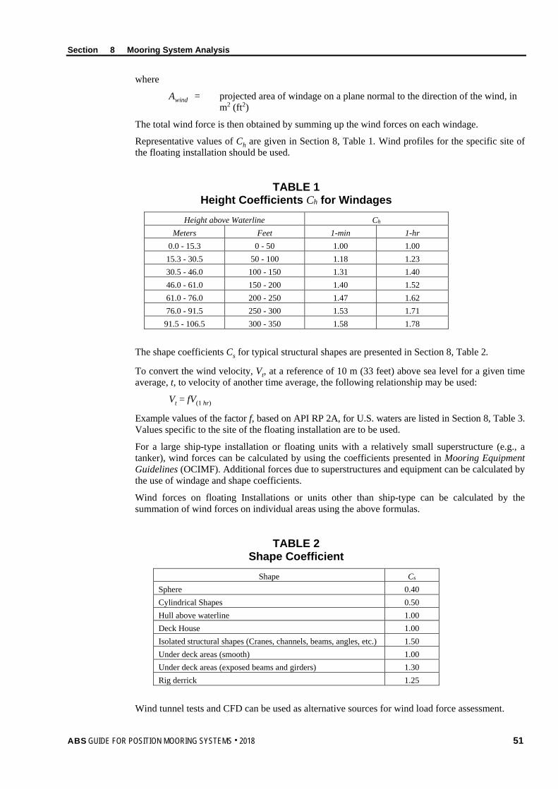
Section 8 Mooring System Analysis
where
Awind = projected area of windage on a plane normal to the direction of the wind, in m2 (ft2)
The total wind force is then obtained by summing up the wind forces on each windage.
Representative values of Ch are given in Section 8, Table 1. Wind profiles for the specific site of the floating installation should be used.
TABLE 1 Height Coefficients Ch for Windages
Height above Waterline Ch Meters Feet 1-min 1-hr
0.0 - 15.3 0 - 50 1.00 1.00 15.3 - 30.5 50 - 100 1.18 1.23 30.5 - 46.0 100 - 150 1.31 1.40 46.0 - 61.0 150 - 200 1.40 1.52 61.0 - 76.0 200 - 250 1.47 1.62 76.0 - 91.5 250 - 300 1.53 1.71
91.5 - 106.5 300 - 350 1.58 1.78
The shape coefficients Cs for typical structural shapes are presented in Section 8, Table 2.
To convert the wind velocity, Vt, at a reference of 10 m (33 feet) above sea level for a given time average, t, to velocity of another time average, the following relationship may be used:
Vt = fV(1 hr)
Example values of the factor f, based on API RP 2A, for U.S. waters are listed in Section 8, Table 3. Values specific to the site of the floating installation are to be used.
For a large ship-type installation or floating units with a relatively small superstructure (e.g., a tanker), wind forces can be calculated by using the coefficients presented in Mooring Equipment Guidelines (OCIMF). Additional forces due to superstructures and equipment can be calculated by the use of windage and shape coefficients.
Wind forces on floating Installations or units other than ship-type can be calculated by the summation of wind forces on individual areas using the above formulas.
TABLE 2 Shape Coefficient
Shape Cs Sphere 0.40 Cylindrical Shapes 0.50 Hull above waterline 1.00 Deck House 1.00 Isolated structural shapes (Cranes, channels, beams, angles, etc.) 1.50 Under deck areas (smooth) 1.00 Under deck areas (exposed beams and girders) 1.30 Rig derrick 1.25
Wind tunnel tests and CFD can be used as alternative sources for wind load force assessment.
ABS GUIDE FOR POSITION MOORING SYSTEMS . 2018 51

Section 8 Mooring System Analysis
TABLE 3 Wind Velocity Conversion Factor*
Wind Duration Wind Duration 1 Hour 1.000 10 Min 1.060 1 Min 1.180 15 Sec 1.260 5 Sec 1.310 3 Sec 1.330
* The values of Section 8, Table 3 are most representative of U.S. waters. Site-specific data should be used. (See 8/3.1.1.)
3.1.2 Squall Load A squall is a strong transient wind event characterized by sudden rapid increases in wind speed and sudden shifts in wind direction. The concept of a wind spectrum is not applicable to squalls. A squall event is normally presented by time series of scalar mean wind speed and associated unit vector mean direction. Squall loading is to be calculated in time domain.
The squall load on hull, superstructures and other objects above-waterline are to be calculated using squalls established in accordance with Subsection 3/3.
The formula given in 8/3.1.1 can be used for the calculation of the load due to squall at each time step with the consideration of relative wind speed and directions to the floating structure/unit.
A number of squall records should be selected for the analysis. As a minimum, the following six critical squall records are to be analyzed.
i) Maximum wind speed
ii) Highest rate of wind speed change
iii) Highest rate of wind direction change
iv) Longest duration of high wind speed
v) Shortest rising time from initial of squall to high wind speed
vi) Shortest time of direction change from initial squall direction to other direction
If there are no squall time records available, a constant wind speed of 100-year one-minute mean wind speed can be used.
3.3 Current and Current Load The current forces on the submerged hull, mooring lines, risers or any other submerged objects associated with the system are to be calculated using a current profile established in accordance with Subsection 3/3. In areas where relatively high velocity currents occur, load amplification due to vortex shedding is to be considered.
Model tests can be used in determining current loads. Alternatively, the following calculation procedures can also be applied.
Current force, Fcurrent, on the submerged part of any structure is calculated as the drag force by the following equation:
Fcurrent = 1/2ρwaterCDAcurrentuc|uc|
where
ρwater = density of sea water, 1.025 tonnes/m3 (1.99 slugs/ft3)
52 ABS GUIDE FOR POSITION MOORING SYSTEMS . 2018

Section 8 Mooring System Analysis
CD = drag coefficient, in steady flow, dimensionless
uc = current velocity vector normal to the plane of projected area, in m/s (ft/s)
Acurrent = projected area exposed to current, in m2 (ft2)
Drag coefficients in steady flow vary considerably with section shape, Reynold’s number and surface roughness and are to be based on reliable data obtained from literature, model or full scale tests.
For a floating structure/unit of a ship-type configuration (e.g., tankers), current forces may be calculated by using coefficients based on model test data as presented in Mooring Equipment Guidelines published by Oil Companies International Marine Forum (OCIMF). Drag coefficients obtained using computational fluid dynamics (CFD) method may be acceptable if the application is well validated and documented.
Section 8, Table 4 provides recommended drag coefficients for mooring lines and risers. Other coefficients can be used if well documented.
TABLE 4 Line Drag Coefficient
Component CD Chain 2.4 Unsheathed spiral wire rope 1.6 Strand rope 1.8 Sheathed rope 1.2 Fiber rope 1.6 Pipe/riser 1.2
3.5 Current and Wind Load under Oblique Environment For environments approaching from an oblique direction, the following equation can be used to evaluate wind and current forces if more accurate predictions are not available.
Fφ = Fx
φ+φ
+
φ+φ
2
2
2
2
sin1sin2
cos1cos2
yF
where
Fφ = force due to oblique environment, in kN (kgf, lbf)
Fx = force on the bow due to a bow environment, in kN (kgf, lbf)
Fy = force on the beam due to a beam environment, in kN (kgf, lbf)
φ = direction of approaching environment, in degrees off bow
3.7 Vortex Induced Motion Where a floating structure/unit is susceptible to vortex induced motion (VIM), the load on the mooring system due to VIM is to be analyzed.
Vortex-induced motions, transverse to and in line with the current, contribute to the offset of the floating structure/unit and hence result in mooring line load. The occurrence of VIM also increases the mean drag force in the current direction. These effects may need to be taken into account for the strength and fatigue design of the mooring system.
ABS GUIDE FOR POSITION MOORING SYSTEMS . 2018 53

Section 8 Mooring System Analysis
3.7.1 Occurrence of VIM Significant VIM can occur if a natural frequency of the moored system lies in the vicinity of the vortex shedding frequency of a major cylindrical component of the platform.
The vortex shedding frequency in steady flow can be calculated by:
fs = St DVc
where
fs = vortex shedding frequency, in Hz
St = Strouhal number
Vc = current velocity, in m/s (m/s, ft/s)
D = member diameter, in m (mm, in.)
The occurrence of significant VIM is related to the non-dimensional reduced velocity Vr:
Vr = s
c
DfV
where
Vr = reduced velocity.
3.7.2 VIM Prediction The VIM analysis is to predict the amplitude of the VIM and the corresponding drag coefficients. The analysis is to include the following:
i) Range of reduced velocity
ii) In-line and transverse VIM response amplitude as a function of reduced velocity
iii) Drag coefficient as a function of VIM response amplitude
iv) VIM response trajectory or envelope
Model testing can be used for the VIM predictions and numerical analysis may provide preliminary assessment of VIM. A VIM model testing is to be well planned and consider the following:
i) Geometric scaling
ii) Dynamic scaling
iii) Hydrodynamic scaling
iv) Modeling of appurtenances
v) Mooring stiffness characteristics
vi) Degrees of freedom
vii) Current direction and profile
viii) Directional resolution
ix) Damping from moorings, floating unit, et al.
x) Blockage (wall) effect
xi) Length of response record
Further guidance for VIM prediction is given in Appendix 2.
54 ABS GUIDE FOR POSITION MOORING SYSTEMS . 2018
Section 8 Mooring System Analysis
3.9 Wave and Wave Load Waves are to be described in terms of wave energy spectra, significant wave height and associated period for the location at which the floating structure/unit is to operate. Waves are to be considered as coming from any direction relative to the floating structure/unit if no site specific wave directions. Waves of less than the maximum height may also need to be considered because the wave-induced motion responses to waves with certain periods may be larger in some cases due to the dynamic behavior of the system as a whole.
3.9.1 Wave Force The wave forces acting on a floating unit, in general, consist of three components:
i) First order forces at wave frequencies
ii) Second order forces at frequencies lower than the wave frequencies
iii) Steady component of the second order forces. This steady component of the wave force is called Mean Drift Force.
Wave force calculation is, in general, coupled with the calculations of dynamic responses of the floating unit for a given environmental condition.
Model test data may be used to predict wave forces for mooring system design provided that a representative underwater model of the unit is tested. Alternatively, a numerical analysis program can be used to calculate the wave forces. The program is to possess the following capabilities as minimum and is to be well validated:
i) Calculation of incident and diffracted wave load
ii) Calculation of added mass and hydrodynamic damping
iii) Consideration of additional damping of the system
A program using the frequency domain or time domain approaches are acceptable.
For a floating unit consisting of slender members that do not significantly alter the incident wave field, semi-empirical formulations, such as Morison’s equation, may be used. In general, application of Morison’s equation may be used for structures comprising slender members with diameters (or equivalent diameters giving the same cross-sectional areas parallel to the flow) less than 20 percent of the wave lengths.
For a column-stabilized type of installation consisting of large (columns and pontoons) and small (brace members) cylindrical members, a combination of diffraction and Morison’s equation can be used for calculation of hydrodynamic characteristics and hydrodynamic loading.
Where applicable, wave force calculations are to account for shallow water effects which increase fluid speed due to blockage effects, change the system natural frequency due to nonlinear behavior of moorings and alter wave kinematics.
3.9.2 Wave Drift Load The second order mean wave drift load and slowly varying wave drift load are to be calculated using appropriate motion analysis computer programs, model tests, or extrapolated from model test results of a similar vessel.
3.11 Wave Induced Motions of a Floating Unit In general, the motions analysis is included in the mooring system analysis, so called coupled analysis that the mooring line effects on the motions and vice-versa are considered in the analysis. If the decoupled analysis approach is used, the motion analysis and the mooring line tension analysis are carried out separately. The motion analysis is to provide the motion inputs for the mooring line tension analysis.
The motion analysis should include the motions due to first order wave frequency, second order low-frequency forces, and steady drift force.
ABS GUIDE FOR POSITION MOORING SYSTEMS . 2018 55
Section 8 Mooring System Analysis
3.11.1 First Order Motions These motions have six degrees of freedom (surge, sway, heave, roll, pitch and yaw) and are at wave frequencies. The motions can be calculated by using appropriate motion analysis software or by model test results of a similar vessel.
3.11.2 Low Frequency Motions These motions are induced by low frequency components of second order wave forces. The low frequency motions of surge, sway and yaw can be substantial, particularly at frequencies near the natural frequency of the system. The low frequency motions can be calculated by using appropriate motion analysis software or by model test results of a similar vessel.
3.11.3 Steady Drift The mean wave drift force and yawing moment are induced by the steady component of the second order wave forces. Mean drift forces and yawing moments are to be calculated using appropriate motion analysis computer programs or extrapolated from model test results of a similar vessel.
5 Mooring System Analysis
5.1 General Mooring system analysis is to be performed to predict extreme responses for mooring line tensions, anchor loads, and vessel offsets under the design environments and other external loads. The responses are then checked against allowable values so that the system has adequate strength against loading and sufficient clearance to avoid interference with other structures. The mooring analysis should consider the following as a minimum:
i) Environmental load including wind, wave and current load
ii) Environmental load induced motions/excursions and mooring line load
iii) Vortex induced motions and mooring line load where applicable
iv) Squall induced motions and mooring line load where applicable
Active control of the mooring system by mooring line adjustment may be performed for certain operations. However, active mooring line adjustment should not be considered in the mooring analysis for maximum design conditions.
5.3 Analysis Model A moored system is a dynamic system that is subjected to steady forces of wind, current and mean wave drift force, as well as wind and wave-induced dynamic forces. Calculations of the maximum mooring system loading are to consider the various relative wind, wave and current forces.
Depending on the level of sophistication and analysis objectives, quasi-static and dynamic analysis methods may be used. Frequency domain, time domain or combined time and frequency domain approaches are acceptable. The designer is to determine the extreme offset and line tension in a manner consistent with the chosen method of analysis. For the final design of a permanent mooring system, the dynamic analysis method is to be employed to account for mooring line dynamics. In deep water and high current areas the current load on mooring lines and risers, which imposed additional loading on the floating vessel, is to be included in the global analysis.
Where applicable, when a quasi-static analysis method is used, the tension in each anchor line is to be calculated at the maximum excursion for each design condition. The excursion is to include the steady state and dynamic responses of the unit of following:
i) Steady mean excursion due to the defined wind, current and mean wave drift forces;
ii) Maximum surge/sway excursions of the unit due to first-order wave excitations
iii) The effects of second order wave-induced motions are to be included for units when the magnitudes of such motions are considered important.
56 ABS GUIDE FOR POSITION MOORING SYSTEMS . 2018
Section 8 Mooring System Analysis
For a single point mooring system, the vessel may experience large low frequency yaw motions. These yaw motions may affect vessel and mooring system responses, and therefore should be accounted for in time or frequency domain simulations as well as in model testing. Care should be taken on the limitation of frequency domain method where variation of yaw angle from the equilibrium position cannot be captured.
The motion amplitude is highly dependent on the stiffness of the mooring system and damping. They are to be properly modeled in the analysis.
Polyester ropes as well as other fiber ropes are made of materials with visco-elastic properties, so their stiffness characteristics are not constant and vary with the load duration and magnitude, the number and frequency of load cycles, and the loading history. In general, polyester mooring lines become stiffer after a long time in service. Historical loading above a certain level may result in a permanent increase of the rope length and a softer mooring system if no re-tensioning is performed. Because of this complex rope behavior, it is not possible to develop models that represent the precise stiffness characteristics of the rope. Currently the industry relies on simplified models that capture the most important characteristics and at the same time yield conservative prediction of line tensions and vessel offsets. Guidance on modeling stiffness of polyester ropes and other fiber ropes are provided in the Fiber Rope Guidance Notes.
The mooring system analysis should take into account the riser loads, stiffness and damping due to the interactions between the mooring system and riser system, unless it can be demonstrated that disregarding some or all riser effects will produce same or more conservative mooring design. Some of the floating production units are equipped with steel catenary risers or midwater flowlines arranged in asymmetric patterns, which may impose large riser or flowline loads on the mooring system. In this case the riser or flowline loads are to be carefully evaluated and properly accounted for.
The effect of water depth should be considered where applicable.
5.5 Initial System Balance and Equilibrium Position The mean equilibrium position of the moored units is calculated from static balance between the mean environmental load, buoyancy, weight of the floating unit and mooring lines, and the mooring system’s restoring force. A stable equilibrium position should be determined before carrying out further dynamic analysis, especially for the analysis in frequency domain. Riser effects are to be considered where their stiffness is relatively high.
5.7 Response to Wave Frequency Force 5.7.1 Frequency Domain Analysis Method
In the frequency domain analysis method, all the parameters are linearized due to the use of the linear principle of superposition. Methods to approximate non-linear effects in the frequency domain and their limitations should be investigated so that the solutions for the intended operation are not compromised.
Frequency domain analysis is to use the equilibrium position based on the environmental mean loads and restoring forces of the mooring lines.
In the frequency domain method, the wave frequency responses can be calculated separately from the low frequency responses. The analysis is to obtain:
i) Motion, velocity and acceleration RAOs of floating units
ii) RAOs of mooring line tensions
iii) Statistical values of the responses, such as standard deviation, significant or maximum responses based on the probability distributions of the peak responses
The wave frequency responses can be combined with low frequency responses to obtain the maximum response value according to the method given in Subsection 3/7 of this Guide.
ABS GUIDE FOR POSITION MOORING SYSTEMS . 2018 57

Section 8 Mooring System Analysis
5.7.2 Time Domain Analysis Method In the time domain analysis approach, all nonlinear effects including line stretch, line geometry, fluid loading, and others nonlinear effects can be modeled.
In this approach, the combined mean, low, and wave frequency response of the floating unit is solved in a time domain. The dynamic equations describing the floating unit, mooring lines, risers, and other forces are all included in a single time domain simulation. The time domain simulation analysis is to obtain:
i) Response time histories of all parameters (floating unit offsets, mooring line tensions, etc.)
ii) Extreme values of the responses through statistical analysis using response time history data. The time domain simulation should be long enough to establish stable statistical peak values.
5.9 Response to Second-Order Low Frequency Force In general, the same methodology for the wave frequency responses is applicable to the analysis of second-order low frequency responses.
In the low frequency analysis, the mooring stiffness and low frequency damping are to be properly modeled and included in the analysis. The prediction of low frequency damping is complicated. The resources of low frequency damping may include:
i) Viscous damping of the floating unit
ii) Wave drift damping of the unit
iii) Mooring system damping
iv) Riser system damping
The basis for the low frequency damping used in the analysis is to be documented.
5.11 Response to Squalls 5.11.1 Ambient Environment and Initial Condition
If there is no specific site information available regarding the equilibrium position (location and heading), the equilibrium position may be determined based on the 1-year return environment of wind waves, swell and current. The equilibrium position determined is to be used as the initial floater’s position for the analysis subject to squalls.
5.11.2 Yaw Damping For a turret mooring system, yaw damping is an important parameter when subject to squalls. However, determination of yaw damping may be difficult. In the absence of better information, the linearized yaw damping coefficient for the turret provided in API 2SK and given below can be used.
CRz = 31 Cy(a
3 + b3)/(a + b) Nm/(Rad/sec)
where
CRz = linear yaw damping coefficient
Cy = linear sway damping, in N/(m/sec)
a = length of vessel forward of turret, m
b = length of vessel aft of turret, m
58 ABS GUIDE FOR POSITION MOORING SYSTEMS . 2018

Section 8 Mooring System Analysis
5.11.3 Simulation of Responses to Squalls Mooring systems subject to squall winds are to be analyzed using a time-domain simulation approach. The length of the simulation time depends on the squall records selected and is to cover the significant variations of the wind speed and wind directions. Squalls characteristics and the responses of mooring systems to squalls are still ongoing research topic. Care is to be taken when selecting squalls for analysis. Among other factors, the following is to be taken into account:
i) Wind Speed. Wind speed is the most important parameter of a squall especially at the early stage of the squall when the turret moored unit is weathervaning, namely unit heading changing from initial to head-on condition. Squalls with high wind speeds are the most critical.
ii) Rate of Speed Change. In general, the higher rate of speed change, the more critical of the squalls.
iii) Rate of Wind Direction Change. The effect of the rate of wind direction change is to be considered with reference to the initial heading of the floating unit.
iv) Duration of the Wind Speed. The longer duration of the high wind speed, the more critical the squalls.
Users should be aware of the latest development on squalls, and sensitivity study for the selected parameters may be necessary.
In the time domain simulation, a proper initial ramp up to the real wind speed may be considered to avoid the sudden transient response at the beginning of the analysis.
5.11.4 Extreme Value of Mooring Load and Offset Regarding responses of mooring loads and offset to squall dominant conditions, the results can be separated into very slowly varying component due to slowly varying squall wind speed, and the frequent varying component mainly induced by waves and wind fluctuation. The statistics for the frequent varying component can be constructed for the maximum value calculation and combined with the very slowly varying component. The most probable maximum value can be used as the extreme value if the number of simulations provide reasonable probability distribute density function. If the simulation number is limited, the maximum value from the simulation results may be used. The methodology for the determination of extreme values is to be documented and submitted to ABS for review.
5.13 Response to VIM The following effects from VIM are to be included in the mooring analysis:
• Drag coefficient in the presence of VIM.
• Offset of floating units due to VIM
• Low-frequency oscillations in mooring line tensions due to VIM
To take these effects into account for strength and fatigue design of the mooring system, the following VIM-related design parameters are to be established:
• In-line and transverse VIM response amplitude (A/D) as a function of reduced velocity (Vr)
• Drag coefficient as a function of VIM response amplitude
These design parameters are to be based on a combination of project specific model test data, previous VIM design experience, and relevant field measurements.
Model testing has been the primary tool for VIM prediction because of the difficulties in obtaining full-scale measurement data and the lack of a sufficiently mature numerical approach. It is usual practice to perform well planned model testing to determine motion amplitudes and drag coefficients for the purposes of mooring design. However, all the model tests conducted to date can only accurately model certain parameters while approximating others. The confidence in model test results and VIM design parameters should be established through adherence to sound engineering principles and comparison with field measurements where available. The reliance on model testing, the limitations of model testing and limited validation with full-scale data are be recognized as potential sources of uncertainty in the design process.
ABS GUIDE FOR POSITION MOORING SYSTEMS . 2018 59
Section 8 Mooring System Analysis
The recommended practice is to develop the design parameters for a base case (the best estimate). Tension safety factors for intact and damaged conditions are to be met for the base case. A sensitivity study related to influential parameters on the design parameters is to be carried out to confirm the robustness of the mooring system (i.e., the risk of mooring failure in the event that estimates of certain influential parameters are inaccurate). The sensitivity check is also used to determine if, with some changes in system parameters, the system would enter a VIM lock-in regime.
Mooring strength analysis for the VIM condition is normally conducted for an extreme current with associated wind and waves. The metocean criteria should specify current velocity, profile, and directions as well as the intensity and direction of the wind and wave conditions associated with the extreme current. Recent experience suggests that consideration is also to be given to extreme wind and waves with associated current as these conditions may produce a larger VIM response.
Mooring tensions due to VIM are cyclic by nature and contribute to the fatigue damage of the mooring system. For long-term fatigue analysis under the VIM condition, current events can be represented by a number of discrete current bins, with each current bin consisting of a reference direction, a reference current velocity and profile, associated wave and wind conditions, and probability of occurrence. Fatigue damage for each current bin is evaluated, and the sum of fatigue damage due to VIM from all current bins is added to the fatigue damage due to wind and waves to determine the total in-place fatigue damage.
In the GOM, a typical loop/eddy current event can last more than one month. Instead of using a constant extreme design current for the whole event, current strength and direction variation based on field measurements for strong loop currents can be considered.
Appendix 2 of this Guide provides more information on the assessment of VIM.
5.15 Multiple Vessels Interaction If floating structures/units are in close proximity to each other, the hydrodynamic interactions, wind and current shielding effects is also to be accounted for in analysis.
7 Fatigue Damage
7.1 General The annual fatigue damage of a mooring line component is to be calculated as the sum of the annual fatigue damage from all the combined environmental parameters, or all sea states. Each sea state may consist of:
• Sea State Direction. Eight to twelve directions can be considered as representing the directional distribution of the long-term environment if no site specific information.
• Probability of occurrence of each sea state
• Mean offset and heading of the floating structure/unit due to the effects of the sea state, with associated wind and current
7.3 Tension-Tension Fatigue Damage For each sea state, the tension range of a mooring line component is to be calculated according to mooring analysis procedures given in Subsection 8/5 of this Guide. Three methods for combining fatigue damage due to low frequency and wave frequency tensions can be used.
7.3.1 Simple Summation Method The simple summation method assumes that the total damage is the sum of low frequency and wave frequency fatigue damages. The simple summation method will generally give an acceptable estimate of fatigue damage if the ratio of the tension standard deviations between wave frequency and low frequency response satisfies the following condition:
f
wf
σσ
≥ 1.5 or f
wf
σσ
≤ 0.05
60 ABS GUIDE FOR POSITION MOORING SYSTEMS . 2018
Section 8 Mooring System Analysis
where σwf and σf are wave frequency and low frequency tension standard deviation, respectively. The simple summation method may underestimate fatigue damage if both low and wave frequency tensions contribute significantly to the total fatigue damage.
Based on a Rayleigh distribution of tension peaks the fatigue damages for sea state i, can be calculated by the following equation:
Di = ( ) ( )
+Γ+
+Γ
212
212 MR
KnMR
Kn M
iLLiM
iWWi
σσ
ni = viTi = viPi ⋅ 3.15576 × 10⁷
where
Di = annual fatigue damage from wave frequency and low frequency tensions in sea state i
nWi = number of wave frequency tension cycles per year for sea state i
RWσi = ratio of standard deviation of wave frequency tension range to reference breaking strength (RBS). The standard deviation of the tension range should be taken as twice the standard deviation of tension.
Γ = Gamma function
nLi = number of low frequency tension cycles per year for sea state i. The average zero up-crossing frequency may be estimated by 1/TN, where TN is the natural period of the vessel computed at the vessel's mean position.
RLσi = ratio of standard deviation of low frequency tension range to RBS. The standard deviation of the tension range should be taken as twice the standard deviation of tension.
vi = zero up-crossing frequency (hertz) of the tension spectrum in sea state i
Ti = time spent in sea state i per year
Pi = probability of occurrence of sea state i
7.3.2 Combined Spectrum Method Combined Spectrum method uses the standard deviation of the combined spectrum to calculate the total damage. Based on a Rayleigh distribution of tension peaks, the fatigue damage for sea state i can be calculated from the following equation:
Di = ( )
+Γ
212 MR
Kn M
ii
σ
ni = vciTi = vciPi ⋅ 3.15576 × 10⁷
The standard deviation of the combined low and wave frequency tension range, Rσi, is computed from the standard deviations of the low frequency tension ranges RLσi, and wave frequency tension ranges RWσi by:
Rσi = 22iLiW RR σσ +
The number of cycles, ni, in the combined spectrum is calculated with the zero up-crossing frequency (hertz) of the combined spectrum, vci, which is given by:
vci = 22WiWiLiLi vv λ+λ
ABS GUIDE FOR POSITION MOORING SYSTEMS . 2018 61

Section 8 Mooring System Analysis
where
vWi = zero up-crossing frequency (hertz) of the wave frequency tension spectrum in environmental state i
vLi = zero up-crossing frequency (hertz) of the low frequency tension spectrum in environmental state i
λLi = 22
2
WiLi
Li
RRR+
λWi = 22
2
WiLi
Wi
RRR+
7.3.3 Time Domain Cycle Counting Method Time domain cycle counting method calculates the fatigue damage using a cycle counting method, such as the Rainflow method, to calculate the number of tension cycles and the expected value of the tension range from a time history of tensions.
7.3.4 Fatigue Damage due to VIM For long-term fatigue analysis, the sum of fatigue damage due to VIM from all current bins is to be added to the fatigue damage from wind and waves to yield total fatigue damage.
The following factors are to be considered when assessing fatigue due to VIM:
i) The oscillation period of the VIM at the offset position corresponding to the specific current bin under consideration is to be used when calculating the number of tension cycles. This period can vary with current direction and magnitude.
ii) The fatigue damage due to a single worst case event, such as 100-year environment conditions or other single worst-case event should be analyzed and added to the total fatigue damage where necessary.
7.5 Bending-Tension Fatigue Damage The assessment of bending-tension fatigue damage includes the analysis of chain tension, relative rotation angle between the chain lines, bending moment, stress concentration factor, and others. The Joint Industry Project of Chain Out-of-Plane Bending has done a lot of research work and has provided recommendations on the assessment of bending-tension fatigue. Appendix 3 of this Guide provides guidelines for the bending-tension fatigue analysis including mooring analysis, FEM analysis and/or static OPB/IPB test that could be conducted to assess the bending damage.
62 ABS GUIDE FOR POSITION MOORING SYSTEMS . 2018
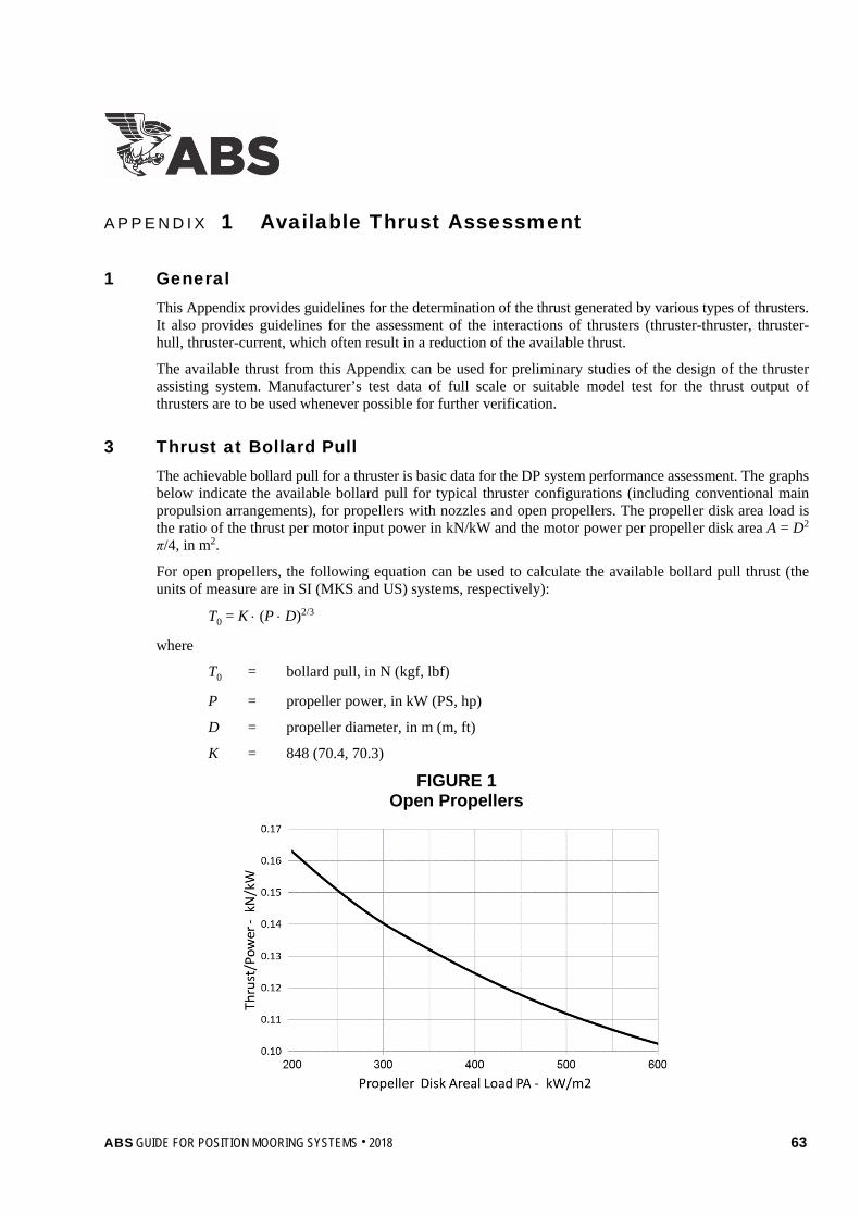
A p p e n d i x 1 : A v a i l a b l e T h r u s t A s s e s s m e n t
A P P E N D I X 1 Available Thrust Assessment
1 General This Appendix provides guidelines for the determination of the thrust generated by various types of thrusters. It also provides guidelines for the assessment of the interactions of thrusters (thruster-thruster, thruster-hull, thruster-current, which often result in a reduction of the available thrust.
The available thrust from this Appendix can be used for preliminary studies of the design of the thruster assisting system. Manufacturer’s test data of full scale or suitable model test for the thrust output of thrusters are to be used whenever possible for further verification.
3 Thrust at Bollard Pull The achievable bollard pull for a thruster is basic data for the DP system performance assessment. The graphs below indicate the available bollard pull for typical thruster configurations (including conventional main propulsion arrangements), for propellers with nozzles and open propellers. The propeller disk area load is the ratio of the thrust per motor input power in kN/kW and the motor power per propeller disk area A = D2 π/4, in m2.
For open propellers, the following equation can be used to calculate the available bollard pull thrust (the units of measure are in SI (MKS and US) systems, respectively):
T0 = K ⋅ (P ⋅ D)2/3
where
T0 = bollard pull, in N (kgf, lbf)
P = propeller power, in kW (PS, hp)
D = propeller diameter, in m (m, ft)
K = 848 (70.4, 70.3)
FIGURE 1 Open Propellers
ABS GUIDE FOR POSITION MOORING SYSTEMS . 2018 63

Appendix 1 Available Thrust Assessment
For ducted propellers, the following equation can be used to calculate the available bollard pull thrust:
T0 = K ⋅ (P ⋅ D)2/3
where
T0 = bollard pull, in N (kgf, lbf)
P = propeller power, in kW (PS, hp)
D = propeller diameter, in m (m, ft)
K = 1250 (103.8, 103.7)
FIGURE 2 Ducted Propellers
5 Thruster-Thruster Interaction The reduction of the thrust output due to thruster-thruster interaction may depend on the following
i) Distance between the thrusters
ii) Azimuth of the thrusters
iii) Diameter of the thruster propeller
iv) Thruster load
v) Thruster design/configuration (i.e., degree of tilt of the propeller and/or nozzle axis)
The following paragraphs describe the thrust reductions for two principal identical thruster configurations.
5.1 In Line Tandem Condition Appendix 1, Figure 3 depicts thrusters in line tandem configuration. The rear thruster operates directly downstream of the other thruster in open water.
64 ABS GUIDE FOR POSITION MOORING SYSTEMS . 2018
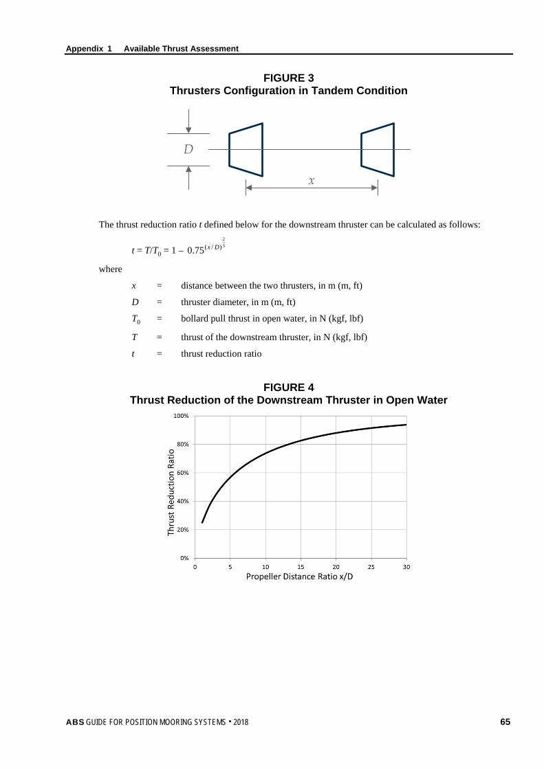
Appendix 1 Available Thrust Assessment
FIGURE 3 Thrusters Configuration in Tandem Condition
x
D
The thrust reduction ratio t defined below for the downstream thruster can be calculated as follows:
t = T/T0 = 1 – 32
)/(75.0 Dx
where
x = distance between the two thrusters, in m (m, ft)
D = thruster diameter, in m (m, ft)
T0 = bollard pull thrust in open water, in N (kgf, lbf)
T = thrust of the downstream thruster, in N (kgf, lbf)
t = thrust reduction ratio
FIGURE 4 Thrust Reduction of the Downstream Thruster in Open Water
ABS GUIDE FOR POSITION MOORING SYSTEMS . 2018 65

Appendix 1 Available Thrust Assessment
5.3 Upstream Thruster Turned Tandem Configuration Appendix 1, Figure 5 depicts the thruster in upstream turned tandem configuration.
FIGURE 5 Thrusters Configuration in Tandem Condition Turning the Upstream Thruster
x
Dφ
The thrust reduction ratio t defined below for the downstream thruster considering steering angles of the upstream thruster can be calculated as follows:
tφ = t + (1 – t)
33
3
/130 φ+
φ
t
where
φ = steering angle, in degrees
t = thrust reduction ratio at zero steering angle
tφ = thrust reduction ratio at steering angle, φ
FIGURE 6 Thrust Reduction of the Downstream Thruster Considering Steering Angles
of the Upstream Thruster
66 ABS GUIDE FOR POSITION MOORING SYSTEMS . 2018

Appendix 1 Available Thrust Assessment
5.5 Forbidden Zones Forbidden zones, also called barred sectors, may be utilized in thruster control to avoid excessive loss due to thruster-thruster interactions. That can be achieved by limiting certain orientations of azimuth thrusters.
The forbidden zones can be calculated using a simple algorithm based on the thruster-thruster interaction effect presented above. The range of the zones shown in Appendix 1, Table 1 depends on the distance between the thrusters and their diameters, and can be determined by the following method:
φf is the angle which minimizes the value of φ⋅φ cost
Td (0° < φ < 45°)
where
φf = range of forbidden zone, in degrees
Td = demanded thrust, in N (kgf, lbf)
tφ = thruster reduction ratio at steering angle φ
FIGURE 7 Range of Forbidden Zone
TABLE 1 Range of Forbidden Zone for Different x/D
x/D Angle (degrees) x/D Angle
(degrees) x/D Angle (degrees)
1 30 6 17.8 11 14.2 2 26.3 7 16.8 12 13.8 3 22.8 8 16 13 13.3 4 20.6 9 15.3 14 13 5 19 10 14.7 15 12.6
In Appendix 1, Figure 7 and Appendix 1, Table 1, x is the distance between the two thrusters and D is thruster diameter.
ABS GUIDE FOR POSITION MOORING SYSTEMS . 2018 67

Appendix 1 Available Thrust Assessment
7 Thruster-Hull Interaction This Subsection provides the methods for the calculation of thrust degradation due to thruster-hull interaction. Consideration of thruster tilt is also provided.
7.1 Friction The thrust degradation due to hull friction is related to the length and breadth of the downstream flow along the hull. The graph below can be used for the assessment of the thrust reduction ratio tf due to the hull friction.
FIGURE 8 Thrust Reduction Ratio due to Hull Friction
7.3 Coanda Effect The Coanda effect is related to the bilge radius and the length of the flow underneath the hull. If no detailed data available, the thrust reduction ratio tc due to Coanda effect can be taken as 97%.
7.5 Pontoon Blockage The blockage of the downstream flow due to presence of the pontoon occurs when a downstream flow is orientated towards the pontoon, such as when the downstream of a thruster on one pontoon is directed towards the opposite pontoon. The reduction of the thrust output due to the pontoon blockage can be calculated using the formula below.
tp = 0.8K ⋅ 55
pL
where
tp = thrust reduction ratio due to pontoon blockage, not greater than 1
Lp = length of the downstream centerline between two pontoons, in m (ft)
K = 1 (0.305)
7.7 Tilted Thruster/Nozzle A tilted thruster can improve the thrust output.
For the tilt angle range from 0 to 8 degrees, the following equation can be applied to determine the improvement of thrust reduction ratio:
68 ABS GUIDE FOR POSITION MOORING SYSTEMS . 2018
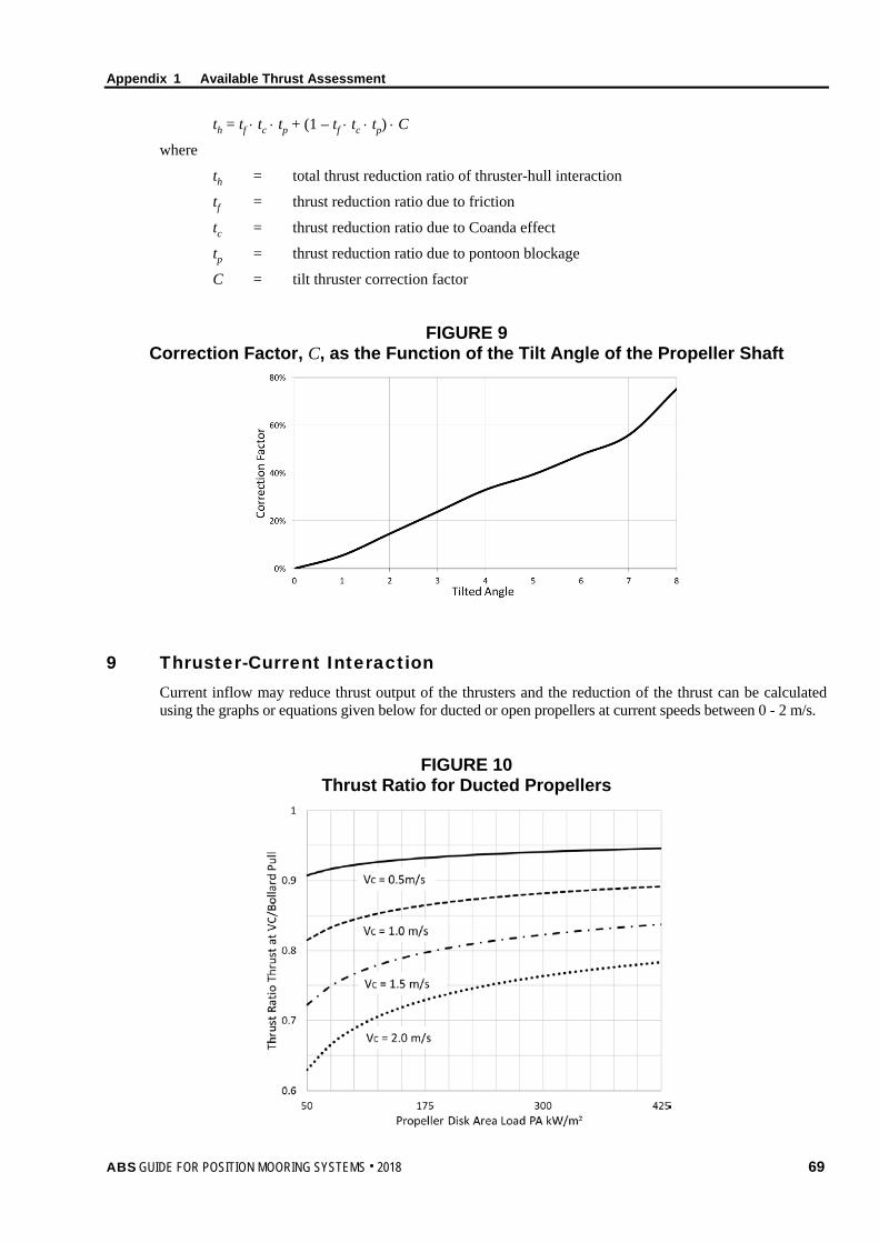
Appendix 1 Available Thrust Assessment
th = tf ⋅ tc ⋅ tp + (1 – tf ⋅ tc ⋅ tp) ⋅ C
where
th = total thrust reduction ratio of thruster-hull interaction
tf = thrust reduction ratio due to friction
tc = thrust reduction ratio due to Coanda effect
tp = thrust reduction ratio due to pontoon blockage
C = tilt thruster correction factor
FIGURE 9 Correction Factor, C, as the Function of the Tilt Angle of the Propeller Shaft
9 Thruster-Current Interaction Current inflow may reduce thrust output of the thrusters and the reduction of the thrust can be calculated using the graphs or equations given below for ducted or open propellers at current speeds between 0 - 2 m/s.
FIGURE 10 Thrust Ratio for Ducted Propellers
ABS GUIDE FOR POSITION MOORING SYSTEMS . 2018 69

Appendix 1 Available Thrust Assessment
For ducted propellers with current speed ranges from 0 to 2 m/s, the following equation can be applied:
EFC = 1 – (K1/PA)0.25 ⋅ K2 ⋅VC
where
EFC = thrust reduction ratio due to current
VC = current speed, in m/s (m/s, ft/s)
PA = propeller disk area load, in kW/m2 (PS/m2, hp/ft2)
K1 = 400 (544, 50)
K2 = 0.11 (0.11, 0.034)
FIGURE 11 Thrust Ratio for Open Propellers
For open propellers with current speed in the range from 0 to 2 m/s, the following equation can be applied:
EFC = 1 – (K1/PA)0.28 ⋅ K2 ⋅ VC
where
EFC = thrust reduction ratio due to current
VC = current speed, in m/s (m/s, ft/s)
PA = propeller disk area load, in kW/m2 (PS/m2, hp/ft2)
K1 = 10 (136, 1.25)
K2 = 0.11 (0.11, 0.034)
70 ABS GUIDE FOR POSITION MOORING SYSTEMS . 2018

ABS GUIDE FOR POSITION MOORING SYSTEMS . 2018 71
A p p e n d i x 2 : V o r t e x I n d u c e d M o t i o n ( V I M )
A P P E N D I X 2 Vortex Induced Motion (VIM)
1 General Many floating units possessing cylindrical structures such as spars, TLPs, and semi-submersibles can be susceptible to vortex induced motion (VIM) when they are exposed to currents.
The parameters that affect the VIM include:
Reduced velocity (see the definition in A2/3.3)
Flow characteristics (flow profile, steady/oscillatory flow, turbulence intensity)
Column geometry
Mass ratio of the column to the displaced fluid
External damping due to mooring and riser
Reynold’s number
Surface roughness
VIM suppression devices, such as strakes configurations (width & length coverage, etc.)
Line pretension
Orientation of floating unit (Semi-submersible)
This Appendix provides guidelines on VIM design parameters, experience in model testing, full scale measurement, strength and fatigue analysis procedures, and methods to minimize VIM.
3 VIM Design Parameters
3.1 Susceptibility of VIM The vortex shedding frequency in steady flow is given by:
fs = St D
Vc
where
fs = vortex shedding frequency, in Hz
St = Strouhal number
Vc = fluid velocity normal to the member axis, in m/s (m/s, ft/s)
D = member diameter, in m (mm, in.)
VIM is expected to occur if the natural frequency of a floating structure/unit coincides with the vortex-shedding frequency. The natural frequency of a moored floating structure/unit is related to the characteristics of the floater and the mooring lines and can be obtained from a mooring analysis program.

Appendix 2 Vortex Induced Motion (VIM)
3.3 Reduced Velocity Vr The reduced velocity, Vr, depends on the natural frequency of the moored floater in horizontal plane, the dimension of submerged columns and the current speed as follows.
Vr =
DTV nc
where
Vc = fluid velocity normal to the member axis, in m/s (m/s, ft/s)
Tn = natural period of the moored floater perpendicular to the current direction, in sec
D = diameter of the column, in m (mm, in.)
Tn is a function of mooring stiffness and the floating units’ mass including added mass, which is typically determined by analytical tools or model testing. Where available, field measurement data should be used to calibrate the added mass values. The mooring stiffness is typically evaluated at the mean offset resulted from current, associated wind and waves. Since the mean offset is a function of drag force, which is dependent on the VIM amplitude, the process of selecting the appropriate offset for VIM calculation is iterative. Calibration of calculated values with available model test or field measurement data may be desirable when such data are available.
VIM can occur under relatively mild currents (for example 1 to 2 knots) if the natural period of the floating unit is long, which may be the case with deep-water mooring systems.
3.5 Transverse (Cross Flow) VIM Transverse VIM occurs when the vortex shedding frequency is close to the transverse natural frequency of a moored floater. The floater typically oscillates in the direction perpendicular to the current in a periodic pattern. The transverse motion is normally expressed as the ratio of single amplitude transverse VIM to the diameter of the column (A/D).
The transverse (lift) force may be given as follows:
qVIM(t) = 21 ρVcDCLsin(2πfst)
where
Vc = characteristic current velocity, typically the highest velocity in the current profile, in m/s (m/s, ft/s)
ρ = density of the fluid, in kg/m3 (kg/mm3, lb/in3)
CL = lift force coefficient
fs = vortex shedding frequency, in Hz
3.7 Inline VIM Inline VIM is the motion in the direction of the current. The magnitude of inline A/D is typically much less than the transverse A/D. Field measurement data for a classic spar with an equally spaced spread mooring system indicate inline A/D is of 10% to 15% of the transverse A/D. However, the magnitude can be higher if the natural period for the inline motion is about half of the natural period for the transverse motion. Also, unsymmetrical mooring system stiffness could result in a VIM trajectory for which the major axis of the VIM is not transverse to the current direction.
Model tests are typically used to determine drag coefficient, Cd, to be used in design. A “base drag” Cd0 is assumed for the case where A/D = 0.0 (no VIM) and amplification factors are applied to account for VIM effects. The drag augmentation is a function of A/D and Vr, which can be expressed as:
72 ABS GUIDE FOR POSITION MOORING SYSTEMS . 2018
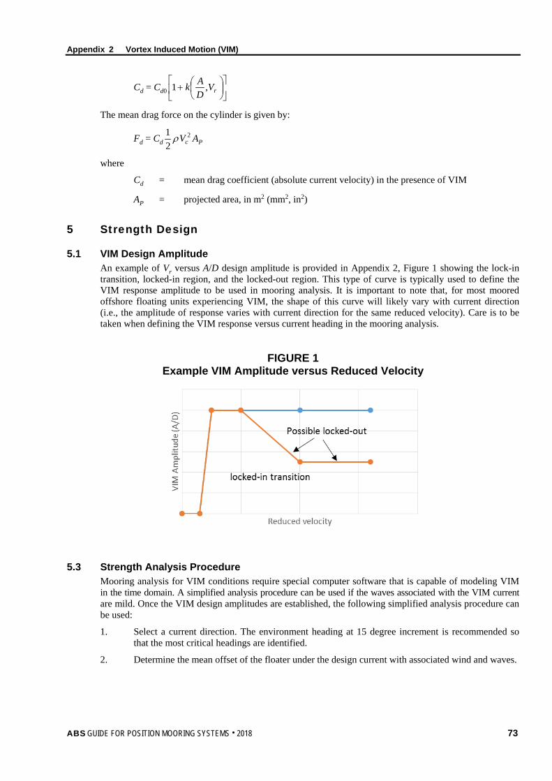
Appendix 2 Vortex Induced Motion (VIM)
Cd = Cd0
+ rV
DAk ,1
The mean drag force on the cylinder is given by:
Fd = Cd 21 ρ 2
cV AP
where
Cd = mean drag coefficient (absolute current velocity) in the presence of VIM
AP = projected area, in m2 (mm2, in2)
5 Strength Design
5.1 VIM Design Amplitude An example of Vr versus A/D design amplitude is provided in Appendix 2, Figure 1 showing the lock-in transition, locked-in region, and the locked-out region. This type of curve is typically used to define the VIM response amplitude to be used in mooring analysis. It is important to note that, for most moored offshore floating units experiencing VIM, the shape of this curve will likely vary with current direction (i.e., the amplitude of response varies with current direction for the same reduced velocity). Care is to be taken when defining the VIM response versus current heading in the mooring analysis.
FIGURE 1 Example VIM Amplitude versus Reduced Velocity
5.3 Strength Analysis Procedure Mooring analysis for VIM conditions require special computer software that is capable of modeling VIM in the time domain. A simplified analysis procedure can be used if the waves associated with the VIM current are mild. Once the VIM design amplitudes are established, the following simplified analysis procedure can be used:
1. Select a current direction. The environment heading at 15 degree increment is recommended so that the most critical headings are identified.
2. Determine the mean offset of the floater under the design current with associated wind and waves.
ABS GUIDE FOR POSITION MOORING SYSTEMS . 2018 73

Appendix 2 Vortex Induced Motion (VIM)
3. Calculate Cd based on the design VIM amplitude established. If this Cd value is significantly different from the estimated Cd used in Step 2, iteration may be required as follows:
i) Peak A/D is selected to determine the drag coefficient Cd used in the calculation of the mean load acting on a floater
ii) Mean load, mean offset and the natural period of the floater are calculated.
iii) With this system natural period, the reduced velocity Vr is calculated, and the corresponding new A/D is found.
iv) The whole process is iterated until the convergent is achieved.
4. Determine the envelope of possible maximum offsets of the floater including the effects of current associated wind and wave (Step 2), in-line and transverse VIM (Step3).
5. Determine line tensions and anchor loads corresponding to the envelope of possible maximum offsets calculated in Step 4 by quasi-static mooring analysis.
6. Evaluate additional line tensions due to transverse and in-line VIM, which is superimposed on the quasi-static values obtained in Step 5.
7. Repeat Steps 1–6 to obtain line tensions and anchor loads for other current directions.
8. Identify the worst direction for design check.
7 Fatigue Analysis
7.1 Long Term Fatigue Damage The recommended procedure for long term fatigue damage evaluation is provided below:
1. Current events can be represented by a number of discrete current bins. Each current bin consists of a reference direction and a reference current velocity with associated wave and wind conditions. The probability of occurrence of each current bin must be specified. The number of reference directions depends on the directionality of the current at the site, and the specified directions are to include those for which significant VIM is predicted. The required number of reference current velocities normally falls in a range of 10 to 50. Fatigue damage prediction can be fairly sensitive to this number for certain mooring systems, and therefore it is best determined by a sensitivity study.
2. Select a current bin and calculate the duration ti for the current bin in a year based on the probability of occurrence for the current velocity and direction.
3. Determine the natural period Tn of the moored unit under the current bin without VIM based on an estimated Cd.
4. Specify extreme in-line and transverse A/D values for the current bin based on available model test or field measurement data. The mean A/D for fatigue analysis can be evaluated by multiplying the extreme A/D with a coefficient g, which should be determined by available model test or field measurement data.
5. Determine in-line and transverse VIM amplitude coefficient Cv, which is a function of reduced velocity, and is equal to 1.0 at peak VIM under lock-in condition.
6. Calculate the reduced velocity for the current bin and further modify the mean in-line and transverse A/D (Step 4) by Cv.
7. Determine drag coefficient Cd for the current bin based on the modified mean transverse A/D (Step 6). If this Cd value is significantly different from the estimated Cd in Step 3, iteration may be required.
8. Perform mooring analysis based on the modified mean in-line and transverse A/D (Step 6), and Cd (Step 7), using the procedure for strength design. Determine average tension ranges Ri, and corresponding average response period Ti from the time trace of line tensions for a few VIM cycles. Note the average response period Ti may vary due to the relative orientation of the mooring line and current.
9. Determine number of cycles to failure Ni corresponding to Ri for the mooring component of interest using an appropriate T-N curve.
74 ABS GUIDE FOR POSITION MOORING SYSTEMS . 2018

Appendix 2 Vortex Induced Motion (VIM)
10. Calculation of annual fatigue damage for the i-th current bin is represented as:
Di = ][ Mi
i REKn
where
Di = annual fatigue damage to the component due to VIM in current bin i
Ni = number of tension cycles encountered in current bin i per year, in sec
][ MiRE = expected value of the normalized tension range Ri raised to the power M, in
current bin i
The number of tension cycles per year in each state can be determined as:
ni = vi ⋅ Ti = vi ⋅ Pi ⋅ 3.15576 × 10⁷
where
vi = zero up-crossing frequency (hertz) of the tension spectrum in current bin i
Ti = time spent in current bin i per year
Pi = probability of occurrence of current bin i
11. Repeat steps 2 to 10 for other current bins.
12. Determine cumulative fatigue damage for all current bins, and then combined with the fatigue damage from wind and waves to obtain total fatigue damage D. The predicted fatigue life is 1/D (years), which is to be greater than the service life times a factor of safety.
7.3 Single Extreme VIM Event It is possible that considerable fatigue damage can be caused by a single extreme VIM event. Therefore in addition to the long-term fatigue damage evaluation, a fatigue analysis for the 100-year VIM fatigue event is also recommended. Since VIM response is largely dependent on reduced velocity, the current for worst case VIM may not coincide with the 100-year return period loop or hurricane current. The highest VIM amplitudes for fatigue consideration could occur under a lower return period current. The current direction is to be the worst direction identified in the strength analysis. Instead of using a constant extreme design current for the whole event, current variation based on field measurements for strong loop currents can be considered. The duration of this event may be different from that obtained from the long term current distribution.
9 Model Testing
9.1 Model Test Parameters 9.1.1 Flow Similitude
The basis for hydrodynamic model testing is that geometric and dynamic similitude between prototype and model fluid flow is preserved. Reynolds number scaling and Froude number scaling are the two relevant scaling parameters for hydrodynamic model testing of offshore structures.
The Reynolds number is defined as:
Re = (VcD)/ν
where
Re = Reynolds number
Vc = characteristic velocity (e.g., flow velocity), in m/s (mm/s, in/s)
D = characteristic length (e.g., hull diameter), in m (mm, in.)
ν = kinematic viscosity of the fluid, in m2/sec (mm2/s, in2/s)
ABS GUIDE FOR POSITION MOORING SYSTEMS . 2018 75

Appendix 2 Vortex Induced Motion (VIM)
The Froude Number, Fn, is defined as:
Fn = gD
Vc
where
g = gravity acceleration, in m/sec2 (mm/s2, in/s2)
Satisfying the Reynolds and Froude scaling simultaneously for the model and prototype flows, however, is practically impossible. For a model dimension D that is substantially smaller than prototype, either the gravity, g, needs to be significantly increased, or viscosity, ν, of the testing fluid needs to be significantly decreased. Neither of these changes is practical in a model basin.
For separated flow dynamics that cause VIM, Reynolds number scaling is the governing scaling law. Reynolds scaling is particularly difficult to achieve for an offshore floating structure. There are currently two basic testing approaches for supercritical and subcritical Reynolds numbers:
• Supercritical Reynolds Number Model Testing. It is important to test at supercritical Reynolds numbers in order to attain a flow regime which is similar to the flow experienced in full scale. However, supercritical Reynolds number model testing places significant demand on the capacity of the model basin and to date supercritical model tests have only modeled 1-DOF and with a uniform current profile.
• Subcritical Reynolds Number Model Testing. For a helically straked cylinder, in the near field flow separation is controlled by the sharp edges of the strakes and not by boundary layer effects. In addition, it is possible to include the effects of 6-DOF motions and current profile in the model test.
As stated above, model tests conducted to date can accurately model certain parameters but only approximate others. Both approaches have advantages and disadvantages, and both show acceptable agreement with full scale data.
9.1.2 Dynamic Similitude In addition to hydrodynamic scaling, dynamic similitude requires that the rigid body dynamics for the full scale and model scale systems are similar. Dynamic scaling is associated with the floating unit’s rigid body modes, mass ratio, and reduced velocity.
Modeling all of the rigid-body modes (e.g., surge, sway, heave, roll, pitch, and yaw) may not be critical as long as modes that are candidates for lock-in are included. The two degrees of freedom might actually couple (lock-in simultaneously). In this case it is important that the sway and roll modes and periods be properly scaled. On the other hand, if the transverse sway is the dominant VIM response, then tests with a single-degree of freedom rigid body mode have shown reasonable agreement between model test and full scale data.
VIM ‘lock-in’ for a typical spar usually occurs for values of 4 ≤ Vr ≤ 10. The reduced velocity for model flow must correspond to the reduced velocity for the prototype flow in order to achieve proper fluid-structure VIM similarity. That is, in addition to selections of proper scaling for Vc and D, scaling for period Tn should also be appropriate.
Mass ratio has a large effect on the range of lock-in, and possibly the amplitude. Mass ratio for a free floating body is by definition equal to 1.0 (displacement = weight). This mass ratio is to be maintained for model tests as well.
9.1.3 Geometric Similitude Geometric similitude is achieved when the geometry of the model and prototype bodies is similar. The geometry of the hull and strakes, if appropriate, is to be accurately scaled. This includes any construction openings in the strakes, brackets, chains, anodes, external pipes and other appurtenances that may affect the flows around the body. Some members may result in viscous damping effects that are Reynolds number dependent. Care is to be exercised to size these members to result in a representative amount of damping in model tests.
76 ABS GUIDE FOR POSITION MOORING SYSTEMS . 2018

Appendix 2 Vortex Induced Motion (VIM)
9.1.5 Damping The VIM response could be affected by damping. The damping (hydrodynamic and mechanical) generated in the model basin is to be consistent with the damping expected in the field. Since mechanical damping may be generated by the testing equipment and is absent in the field, care is to be taken to understand the effect of damping on the VIM response and to mitigate such effects. Hydrodynamic damping, due to mooring lines, risers and wave effects should be considered in the model test if possible and should be included when estimating the amplitude the VIM.
11 Methods to Improve Mooring Design for VIM
11.1 Polyester Rope for Middle Section The use of polyester ropes in the middle section of mooring lines may sometimes minimize VIM due to the relative flexibility of the rope along the water depth when subject to current load. Also, the use of polyester rope may reduce Vr, which in turn may prevent lock-in.
11.3 Improved Chain Fairlead The chain section in contact with the fairlead is more susceptible to fatigue failure because of the presence of bending loads in addition to tension. Chain fairleads with seven pockets are commonly used for spar moorings. The use of chain fairleads with nine pockets can reduce chain bending, thus reducing chain fatigue damage in this section. Also chain fairlead design resulting in a tight fit between the chain and the fairlead pocket can yield a much lower stress concentration factor and longer fatigue life. Alternatively, bending shoes that yield low stress concentration in chain can be used.
11.5 Strake Design VIM can be reduced by improved strake design. Options include improving strake shape, increasing strake height, and eliminating discontinuities and holes in strakes. To evaluate the effectiveness of these options, a rigorous model test program is required.
11.7 Hull Appurtenances Hull appurtenances such as anodes, chain, fairleads, and pipes may affect spar VIM response. Measures to eliminate or reduce the adverse impact of these appurtenances may reduce VIM. A rigorous model test program is required to evaluate the effectiveness of these measures.
11.9 Tightened Mooring VIM is not observed in the model basin when Vr is below a threshold value. This condition can be achieved in some cases by tightening the mooring system. For example using higher initial tensions, or tightening the mooring system in advance of high current events, thus reducing the natural period of the moored floating unit, and eliminating VIM for current speeds below the maximum design value. The adoption of this measure is to be based on rigorous model testing and analysis, and on addressing sensitivity to higher current and lower threshold Vr. An operational procedure for a tight mooring during high current events is also to be developed.
ABS GUIDE FOR POSITION MOORING SYSTEMS . 2018 77

78 ABS GUIDE FOR POSITION MOORING SYSTEMS . 2018
A p p e n d i x 3 : M o o r i n g C h a i n F a t i g u e D u e t o B e n d i n g
A P P E N D I X 3 Mooring Chain Fatigue Due to Bending
1 General Out of Plane Bending (OPB) can occur in links at the connection between mooring lines and the moored floater where adjacent chain links have relative angular movement, see Appendix 3, Figure 1. Those links are subject to bending induced stress in addition to tension-tension stress, which should be included in the fatigue assessment.
This Appendix provides informative guidance on the assessment of OPB fatigue calculations.
FIGURE 1 Interlink Out of Plane Bending (OPB)
3 Interlink Stiffness and Sliding Threshold
3.1 Interlink Bending Moment and Contact Stiffness The bending stress of a chain link is a function of the mooring chain tension and the interlink rotation angle. The higher the tension and rotation angle, the higher the bending moment on the chain link.
The interlink OPB bending moment and the OPB stress can be expressed as follows:
MOPB = k 1610014.0
22
2
dd
d
Tbaa
OPB = MOPB/16
2d
where
d = chain nominal diameter, in m (mm, in.)
T = line tension, in N (kgf, lbf)
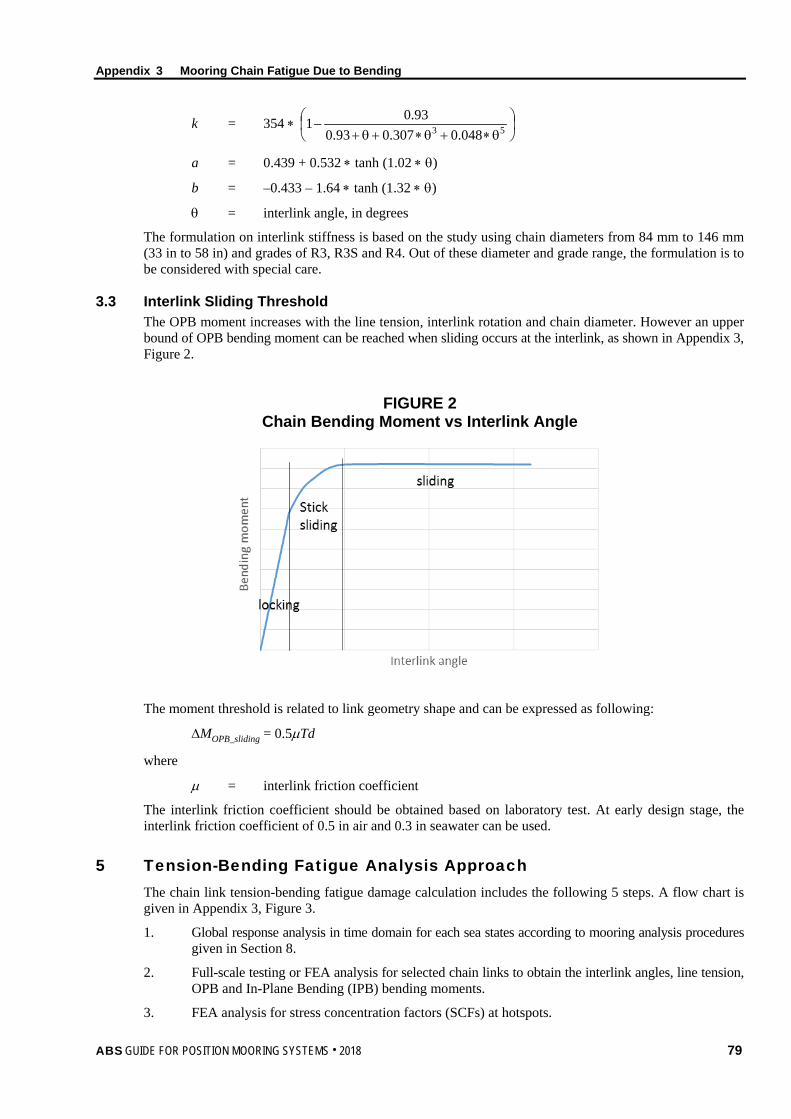
Appendix 3 Mooring Chain Fatigue Due to Bending
k = 354 ∗
θ∗+θ∗+θ+− 53 048.0307.093.0
93.01
a = 0.439 + 0.532 ∗ tanh (1.02 ∗ θ)
b = –0.433 – 1.64 ∗ tanh (1.32 ∗ θ)
θ = interlink angle, in degrees
The formulation on interlink stiffness is based on the study using chain diameters from 84 mm to 146 mm (33 in to 58 in) and grades of R3, R3S and R4. Out of these diameter and grade range, the formulation is to be considered with special care.
3.3 Interlink Sliding Threshold The OPB moment increases with the line tension, interlink rotation and chain diameter. However an upper bound of OPB bending moment can be reached when sliding occurs at the interlink, as shown in Appendix 3, Figure 2.
FIGURE 2 Chain Bending Moment vs Interlink Angle
The moment threshold is related to link geometry shape and can be expressed as following:
∆MOPB_sliding = 0.5µTd
where
µ = interlink friction coefficient
The interlink friction coefficient should be obtained based on laboratory test. At early design stage, the interlink friction coefficient of 0.5 in air and 0.3 in seawater can be used.
5 Tension-Bending Fatigue Analysis Approach The chain link tension-bending fatigue damage calculation includes the following 5 steps. A flow chart is given in Appendix 3, Figure 3.
1. Global response analysis in time domain for each sea states according to mooring analysis procedures given in Section 8.
2. Full-scale testing or FEA analysis for selected chain links to obtain the interlink angles, line tension, OPB and In-Plane Bending (IPB) bending moments.
3. FEA analysis for stress concentration factors (SCFs) at hotspots.
ABS GUIDE FOR POSITION MOORING SYSTEMS . 2018 79

Appendix 3 Mooring Chain Fatigue Due to Bending
4. Calculation of total stress at selected hotspots.
5. Calculation of chain link fatigue damage using rainflow cycle counting from the stress time history and appropriate S-N curve.
7 Tension-Bending Fatigue Damage Calculation
7.1 Combined Stress Range In the case of tension-tension loading, the hot spot locations are at the transition from the straight legs to inner bend and at the outer crown. In the case of OPB loading, the hotspots are located in the inner bend region, close to the contact area between the two links. There are four OPB hotspots on each side of the chain link that have similar OPB and IPB amplitudes but with different directions. For a given loading combination of tension, in-plane and out-of-plane angle variation, each simultaneous stress range contribution can be added using the following formula:
∆σcombined = ∆σnom,TTSCFTT ± ∆σnom,OPBSCFOPB ± ∆σnom,TIPBSCFIPB
7.1.1 TT stress The tensile stress range can be calculated as follows:
∆σnom,TT = 22
dT
π∆
where
∆T = tension range, in N (kgf, lbf)
7.1.2 OPB stress The relationship between the OPB stress range and the interlink OPB bending moment range is as follows:
∆σnom,OPB = 316
dM OPB
π∆
7.1.3 IPB stress The relationship between the IPB stress range and the interlink IPB bending moment range is as follows:
∆σnom,IPB = 333.2
dM IPB
π∆ for studless chain
∆σnom,IPB = 306.2
dM IPB
π∆ for stud link chain
80 ABS GUIDE FOR POSITION MOORING SYSTEMS . 2018

Appendix 3 Mooring Chain Fatigue Due to Bending
FIGURE 3 Flow Chart to Calculate OPB Fatigue Damage
Global motion and mooring analysis for each
sea states selection
• Time series of tension T at fairlead• Time series of fairlead angle
Transfer global angles to interlink angle and moment
Time series of nominal tension, OPB and IPB stresses
Calculate combined stress with SCF for each hot spot:∆σcomb = ∆σnom,TTSCFTT ± ∆σnom,OPBSCFOPB ± ∆σnom,IPBSCFIPB
Rainflowcycle counting
S-N curve
Tension-Bending Fatigue damage
Evaluate:• Interlink angles of in-plane and out-of-
plane of each link• Interlink moment in-plane and out-of-plane
of each link with moment threshold• SCFTT, SCFOPB, and SCFIPB
Static OPB/IPB test, or FEA model, or both with interlink stiffness
Chain link geometry and property
7.3 Stress Concentration Factors (SCFs) Cyclic stresses and corresponding stress concentration factors for the different loadings are defined as follows:
SCFTT = TTnom
TT
,οο
∆∆
SCFOPB = OPBnom
OPB
,οο
∆∆
SCFIPB = IPBnom
IPB
,οο
∆∆
Finite element analysis (FEA) is recommended for T-T, IPB and OPB loading and SCF calculations at OPB hotspots using nominal link shape.
ABS GUIDE FOR POSITION MOORING SYSTEMS . 2018 81

Appendix 3 Mooring Chain Fatigue Due to Bending
7.5 S-N Curve An S-N curve should be established based on sufficient full scale OPB fatigue test data and linear regression analysis. Two standard deviations may need to be considered to determine the S-N curve for the fatigue damage assessment. The Joint Industry Project of Chain Out-of-Plane Bending recommends a single slope design S-N curve of:
NTM = K
where log K = 12.575 and M = 3.
The curve is based on the testing data in sea water under free corrosion condition.
9 Mitigation Method Chain links with high tension loads and constrained relative rotation are prone to bending-tension fatigue damage. The following methods can be considered for the mitigation of the OPB induced fatigue damage:
• Doubly articulated chain stopper to reduce the effect of motions of the floating structure on the mooring line
• Use of very low friction bushings in chain stoppers
• Reduce pretension to reduce OPB stress
• Increase the lever arm or hawse pipe length between bushings and first chain link
• Off-set the chain stopper
• Careful orientation of the link at the end of the hawse pipe
• Straight chain hawse may be superior to curved chain hawse for minimizing the OPB, as the straight hawse tends to evenly spread the chain rotation among several interlinks while the curved one may result in concentration of the chain rotation to a single interlink
• A periodically shift of the chain links at the fairlead so additional fatigue damage due to bending can be more evenly distributed
82 ABS GUIDE FOR POSITION MOORING SYSTEMS . 2018