portable pinhole test apparatus - nrcs irrigation toolbox...
TRANSCRIPT

United States Department of Agriculture
SOIL MECHANICS 2 10-VI
Soil Consewaton Service
P.Q. Box 2890 Washington, D.C. 208 13
June 29, 1987 NOTE NO. 12
SUBJECT: ENG - PORTABLE PINHOLE TEST APPARATUS
Purpose. To distribute Soil Mechanics Note No. 12 (SMN-12).
Effective Date. Effective when received.
Dispersive soils have been the cause of excessive erosion in some SCS practices or structures such as dams or channels. Laboratory tests such as the pinhole test have been developed to identify dispersive soils so that they can be avoided or treated to prevent the erosion caused by dispersive characteristics. It is important to identify any dispersive soils as they may be used in construction or be in contact with water when associated with conservation practices or engineering structures. This is usually done by obtaining field samples of the soils involved and sending them to a laboratory for testing.
There are times when dispersive soils need to be identified or soils need to be checked for dispersion without the delay of sending samples to the laboratory. This is particularly needed during the construction process.
A portable pinhole testing device has been designed, assembled and found suitable for use in field testing. This soil mechanics note gives the detailed plans for constructing the field test device and includes a list of the components and assembly instructions. It also includes test procedures and criteria for data evaluation.
Filing Instructions. File with other soil mechanics notes with guide material on identification of dispersive soils or with guide material on construction testing of soils.
Distribution. This- soil mechanics note will be of interest to soil engineers, design engineers, area engineers, project engineers, engineering geologists and others who may be investigating, designing, or constructing practices or structures where dispersive soils need to be identified. The initial distribution to each state and NTC is according to requested numbers indicated in a survey for SMN-1 (shown on the reverse side). Additional copies may be obtained by ordering SMN-12 from Central Supply.
f j @ @ d a n ' f BER R. SHAW fi" Deputy Chief for Technology
The Soil Conservation Service is an agency of the Department of Aariculture


U.S. Department of Agriculture Soil Conservation Service
Engineering Division
SOIL MECHANICS NOTE NO. 12
PORTABLE PINHOLE TEST APPARATUS
June 1987


I. Purpose
The pinhole test is a direct measurement of the dispersibility (colloidal erodibility) of fine-grained soils. There is a need for equipment that can be used in the field to make this test.
11. Scope
This note provides a list of the'basic components of test apparatus, inatructions on how to assemble the apparatus, and a test procedure that includes criteria for data evaluation.
111. Test Apparatus
The apparatus can be constructed from commercially available components. It is suitable for use in either a laboratory or a field operation. The portable pinhole device was designed by the Soil Mechanics Laboratory, Lincoln, Nebraska.
The apparatus consists of (1) a Soiltest Model K-620 permeameter that is modified to serve as the pinhole test chamber, (2) a 10-liter aspirator bottle that is modified to serve as a constant-head water supply, and (3) a Soiltest Model CN-430 compaction tamper.
IV. Apparatus Components
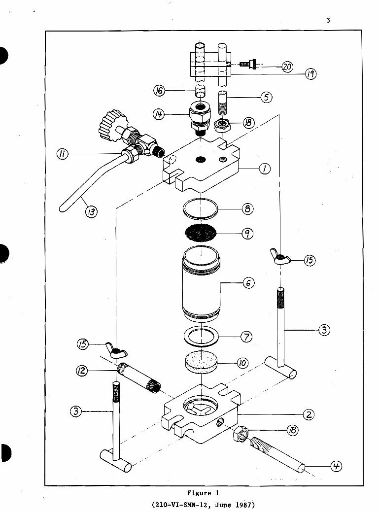
A disassembled model K-620 permeameter is shown on figure 1 and on plate 1. The modification (except for fittings) of the model K-620 permeameter is made on the base (part No. 2, figure 1). It consists of cutting a groove for an *'Ow ring gasket and drilling a small diameter hole as shown on figure 2 and plate 2. The small diameter vent hole is required to maintain atmospheric pressure at the base of the specimen. The "0" ring gasket provides a seal and also secures the barrel to the base during preparation of the specimen. For proper sample preparation the barrel of the pinhole test chamber must be secured to the base, the "Ow ring works very well for this purpose.
V. Procedure
The apparatus is basically the same as the equipment used to develop the pinhole test at the SCS Soil Mechanics Laboratory, Lincoln, Nebraska. The pinhole test procedure and the interpretation guides developed at the SML can be used directly with this apparatus. They are included in appendix B.
The fittings modification is to facilitate hookup to the water supply and to add a manometer to measure water pressure in the test chamber at the top of the specimen. Figure 2 and plate 3 show all the component parts. A parts list is included in appendix A.
This note prepared by Lorn P. Dunnigan, Soil Mechanics Laboratory, Lincoln, Nebraska
(210-VI-SMN-12, June 1987)

The constant head water supply is provided by installing a bubbling tube through the cap of a 10-liter aspirator bottle. A 10-liter aspirator bottle like Cole-Parmer No. K-6080-42 is necessary to (1) get a large enaukh outlet (for 1/2-inch tube) from the bottle, and (2) get a tight fitting bottle cap that is large enough so that it can be drilled to receive the bulkhead union connector and the bubbling tube. The bottle cap and the bubbling tube connections have to be airtight in order to maintain atmospheric pressure at the bottom of the bubbling tube. A picture of the bottle cap and the bubbling tube assembly is shown on plate 4.
The bubbling tube apparatus is made by drilling a 5/8-inch-diameter hole through the bottle cap. The bulkhead union connector is inserted through the bottle cap with the long threads down. A 5/8-inch I.D. "Ow ring is placed between the bulkhead union connection and the bottle cap to form a tight seal. The tube-to-tube bulkhead union connector as received con- tains a stop ring inside that prevents the connector from sliding com- pletely over the tube. The stop ring can be removed by reaming with a 25/64-inch drill bit to the depth necessary to remove the ring. This will allow the bubbling tube to extend through the connector and it can be moved upward or downward for calibrating the head on the test chamber.
The manometer consists of a length of extruded acrylic tubing. The manometer can be easily connected and disconnected from the pinhole device. Reference marks can be made on the tube at the common test heads of 2 inches and 7 inches above the center of the test specimen (pinhole location), or a 4-foot reference tape can be used.
A stand to hold the constant-head bottle can easily be constructed. The stand shown in plate No. 5 and figure No. 3 is made so that the bottle stays in a fixed position and the pinhole test chamber is moved for the trials at the 2-inch and 7-inch heads. Dispersive clays can be identified by testing at the 2-inch head. Most field tests will probably not be carried beyond the 7-inch head. It is possible, however, to lower the test chamber for tests at heads of 15 inches and 40 inches. If this is planned, then a connecting tube and a manometer at least 40 inches long will be needed.
(210-VI-SMN-12, June 1987)
(210-VI-SMN-12, June 1987)

Figure 2
(210-VI-SMN-12, June 1987)
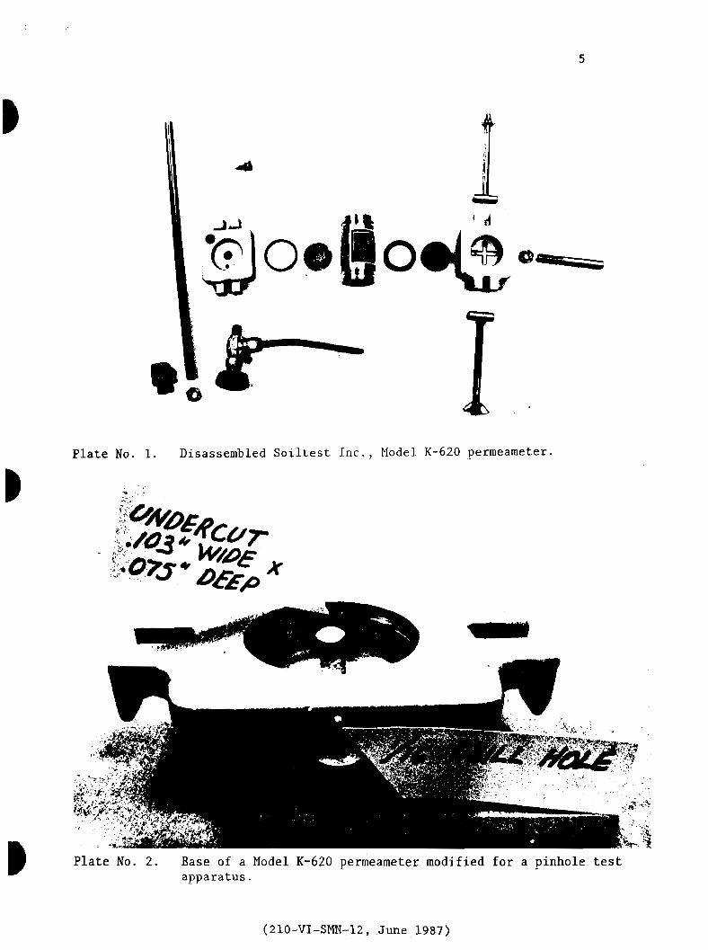
Plate No. 1. Disassembled Soiltest Inc., Model K-620 permeameter.
(L r
<- ,
Plate No. 2. Base of a Model K-620 germeameter modified for a pinhole test apparatus.
(210-VI-SMN-12, June 1987)
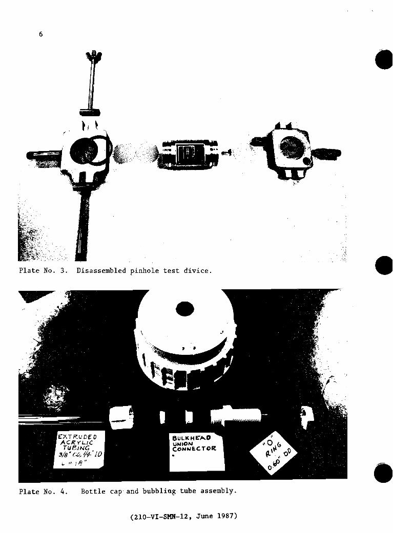
Plate No. 3. Disassembled pinhole test divice.
Plate No. 4. Bottle cap and bubbling tube assembly.
(210-VI-SMN-12, June 1987)

Plate No. 5 Stand for constant head b o t t l e and for the pinhole test chamber. --
Plate No. 6 .
Portable pinhole test apparatus.
(210-VI-SMN-12, June 1987)

PLAN
-
ELEVATION
MATERIAL LIST
@ 9; x IS' Base
@) 7: x 13; Long support
@ 7;' x 9;' Tronsverse support
@ 4' x 4 f Shelf support
@ 3:' x 5f Shelf
@ x g x 3f Stop block, 2 each
Glue, 6 d fin. nails, I" brads
( Use f plywood or $ lumber)
I I I
. 2 4
CUTTING DlAGRAM FOR PLYWOOD
Figure 3
(210-VI-SMN-12, June 1 9 8 7 )

VI Appendix: Parts for Pinhole Test Device
Note: Item numbers 1 through 20 are for the complete Soiltest Permeameter, catalog No. K-620.. Item numbers 21 through 26 represent the materials needed to modify the germeameter to a pinhole test device.
eat P e w t e r Model K - 620 ( F W r e No. 11 Parts List
Item No.
1 2 3 4 5 6 7 8 9
10 11 12 13 14 15 16 17 18 19 20
No. part No. pescri~tion Required
TOP Base Tie Rod Assembly Clamping Rod Guide Rod Pipette Compaction Mold Gasket (Base) Gasket (Head) 200 Meah Screen Porous Stone Valve Long Nipple 1/8 N.P.T. x 2" Overflow Tube Male Connector 1/8 N.P.T. to 3/8 1/4-20 Wingnut Type "A" Pipette 1/4 Saran x ,031 Wall 3/8-16 Hex Jam Nut Pipette Guide Support No. 10-32 x 1/2 Knurled Screw
Tube
(Only item Nos. 1, 2, 3, 6, 8, 12, and 15 are retained)
Pinhole Test Device . ..xermeame=
Parte List
1 1 2 1 1 1 1 1 1 1 1 1 1 1 2 1
Coil 2 1 1
K-620-2 Base, modify by drilling vent hole 1 (Soiltest) and machining an O-ring groove; see
figure 2 and plate No. 2.
K-6450-12 Male pipe adapter, 1/8-inch MIPT to 3/8-inch I.D. Tubing. (Cole-Parmer)
K-6385-10 Male Connector, MPT, 1/8-inch to 1 1/4-inch O.D. Tube. (Cole-Parmer)
Item No. 14 can be uued instead of item 22.
(210-VI-SMN-12, June 1987)

Screen, 14 wires per inch; obtain window screen locally, cut to 1-1/4" diameter circle.
O-ring, 1-3/811 diameter, cross section of 0.103 inches (obtain locally).
Conical nipple, machine from metal or plastic (obtain locally). See drawing for dimensions.
Extruded acrylic tubing, 1/4" OD, 1/8" ID, length 40" (for measuring head on pinhole device) fits item No. 22. (Cadillac Plastic and Chemical Company)
Extruded acrylic tubing, 3/8" OD, 1/4" ID, length 40", fits item No. 14
PARTS FOR WATER SUPPLY
1. Aspirator bottle; 10 liter with an outlet low on the bottle to connect to 1/2" tube. Top closure must be leakproof.
2. Bulkhead Union Connector tube to tube for 3/8" OD tube.
Cole-Parmer No. K-6390-30
3. Extruded acrylic tubing, 3/8" OD, 1/4" ID. (Rigid plastic tube for bubbling tube, 18" length required and for manometer, 12 1/2" length required.)
4. Tubing, gum rubber, 3/8" ID, 1/2" OD, 40" length required. Connects aspirator bottle to pinhole device. This tubing will fit the 1/2" bottle outlet when stretched.
Cole-Parmer No. K-6833-00
5. Clamp, tubing flow valve. (Use on gum rubber tubing.)
PLE PREPARATION AND TEST EQUIPMENT
1. Compaction tamper, Soiltest Inc., CN-430
2. Yale Hypodermic Needle, No. 19, Popper and Sons, Inc., reorder No. 7067, Box of 12
(210-VI-SMN-12, June 1987)

3. Graduated cylinder, glass, 100 ml, 50 ml, 25 ml, and 10 ml--laboratory and/or chemical supplies
Note: Add 3/16" washers under item 15, wingnut.
4. Stop watch--GSA
5. Putty knife--1 1/4" like Red Devil 4302--GSA or local
6. Teaspoon--GSA or local
7. Pea gravel (1/4" to 3/8" size)
8. Distilled water
9. Teat data sheet
Source for component parts
Soiltest, Inc. 2205 Lee Street
Evanston, Illinois 60202 Phone: 312-869-5500
Cole-Parmer Instrument Company 7425 North Oak Park Avenue Chicago, Illinois 60648 Phone: 1-800-323-4340
Cadillac Plastic and Chemical Company 15111 2nd Avenue
Detroit, Michigan 48203 Phone: 1-800-521-4004
Donley Medical Supply Company 2425 '0' Street P.O. Box 83108
Lincoln, Nebraska 68501 Phone: 402-474-3222
(Popper and Son, Inc., Hypodermic Needle)
(210-VI-SMN-12, June 1987)


VII Appendix: Pinhole Test
Purwose
This is a test for direct measurement of the dispersibility (colloidal , erodibility) of compacted fine-grained soils. Water is caused to flow
through a small hole punched in a specimen. The water running through samples of dispersive clay carries a cloudy colored suspension of col- loidal particles, whereas the water running through erosion resistant clay is crystal clear.
Sample Preparation
1. Soil samples must be preserved at natural moisture contents by shipping and storing them in airtight bags or containers.
2. If the material contains coarse sand or gravel particles, these are removed by gently working the material through the No. 10 (2 mm) sieve.
3. The natural moisture content is measured and the moisture content is brought to near the plastic limit by adding distilled water (or by gradually drying, if too wet).
1. The test specimen and the apparatus are shown schematically in figures B-1 and B-2. Prior to compacting the test specimens, place the screens and pea gravel.
2. The test specimen is compacted in the cylinder on top of pea gravel and wire screen. It is compacted in five layers with 16 tamps per layer (15 lb spring) with a Harvard miniature compaction test tamper. This pro- cedure gives about 95 percent of ASTM D 698 compaction. NOTE: A heaping teaspoon of soil is about the right amount for one layer. The end of the 1 1/4-inch putty knife rotated around works very well for leveling the surface of the specimen prior to insertion of the plastic nipple,
3. The plastic nipple is pushed into the top of the specimen with finger pressure. A hole is punched in the specimen through the nipple with a 1.0 millimeter-diameter-stiff steel wire (No. 19 hypodermic needle). The needle should penetrate into the pea gravel. Place the screens and gravel on top of the specimen as shown in figures B-1 and B-2 and assemble the apparatus.
4. After the apparatus is assembled, water is percolated through the hole in the sample under heads of 2 inches, 7 inches, 15 inches, and 40 inches for time periods of 5 to 10 minutes at each head, The quantity of flow is measured with a stop watch and graduated cylinders. Start with a 10 ml graduated cylinder and as flow increases, go to a 25 ml or 50 ml graduated cylinder as necessary. Measure the flow continuously and record the time to fill each graduated cylinder as shown on typical data sheets (figures B-3 and B-4). Cloudiness of water is observed by looking both through the side of the graduated cylinder and vertically through the
(210-VI-SMN-12, June 1987)

column of water in the graduated cylinder. NOTE: Dispersive clays, Dl and D2 are determined at a 2" head; ND3 and ND4 are determined at a head of 7" or less. It may not be necessary to go beyond a 7" head in field t e s t applications if the main purpose of the test is to distinguish between dispersive and nondispersive soils.
5 . At the end of successive flow tests, the apparatus is dismantled. The soil specimen i a extruded from the cylinder and broken open so the size of the hole can be examined. The size is measured approximately by comparison with the needle used for punching the hole.
Criteria for Evaluating Results
1. At 2-inch head
a. The test is started with a head of 2 inches. (If no flow occurs, stop the test, dismantle the top of the apparatus, and repunch the hole or seal the first hole and make a new one. No flow occurs rarely.)
b. The principal differentiation between dispersive and nondispersive soils is given by test results under 2 inches of head. If flow under 2 inches of head is visibly cloudy and does not become clearer vith time, the specimen is failing in the fashion typical of dispersive clays. The main indicator of failure is the colloidal color of the water. Most dispersive clays erode rapidly under 2 inches of head with pronounced color in the water coming through the specimen. For dispersive clays, usually the flow continuously increases and reaches a maximum value lim- ited by the hydraulic capacity of the equipment in 2 to 5 minutes of flow (about 1.5 to 2.0 ml/s, using the nipple and Harvard miniature permea- meter). Continue running the test for a total of 10 minutes. Unless the color of the water clears substantially, the test is completed for the typical dispersive clay. The hole will normally be increased to about 3 needle diameters after 10 minutes of flow. Classify as highly dispersive (DI)
c. If the flow at 2 inches of head has slight but easily visible color as seen from the side of the graduated cylinder at the end of 5 minutes, continue the test for a total of 10 minutes. If the flow continues colored, stop the test. If the rate of flow at the end of 10 minutes has not exceeded 0.8 ml/s, and the hole diameter exceeds 2 needle diameters, classify as dispersive (D2). If the test is stopped at the end of 10 minutes and the results classify as ND4 and D2, the test should be repeated with a new specimen to see what happens by raising the head to 7 inches,
d . If flow under 2 inches of head is clear (or has only a very light trace of color as seen from the side of the graduated cylinder) at the end of 5 minutes, raise the head to 7 inches and continue the test (rate of flow is usually 0.3 to 0.6 ml/s).
(210-VI-SMN-12, June 1987)

2. At 7-inch head
a. If the water continues to flow clear or has only a trace of color as seen from the side of the graduated cylinder, raise the head to 15 inches after 5 minutes of flow and continue the test (rate of flow is usually less than 1.8 ml/s).
b. If the water has color and rate of flow increases rapidly, stop the test. Classify as intermediate ND3. The flow at the end of the test will generally exceed 2.5 ml/s, and the hole size will be larger than 2 needle diameters.
3. At 15-inch head
a. If the flow is completely clear as seen from the top of the graduated cylinder, raise the head to 40 inches after 5 minutes (rate of flow is usually less than 2.5 ml/s).
b. If the flow has slight color or exceeds 3.5 ml/s, stop test, and classify nondispersive (ND1).
4. At 40-inch head
a. If the flow continues completely clear at rate usually less than 4.0 ml/s, classify as nondispersive (ND1). There should be no noticeable erosion of the hole in the sample at the end of the test.
b. If the flow has a bare trace of color or exceeds 5.0 ml/s, classify as nondispersive (ND2) .
5. Examples of test data for typical dispersive clay (Dl) and for a typical nondispersive clay (ND1) are shown in figures 5 and 6.
6. Criteria for evaluating test results are summarized in table B-1.
7. Interpretation and report.
a. The interpretation of test results is outlined in table B-2.
(210-VI-SMN-12, June 1987)
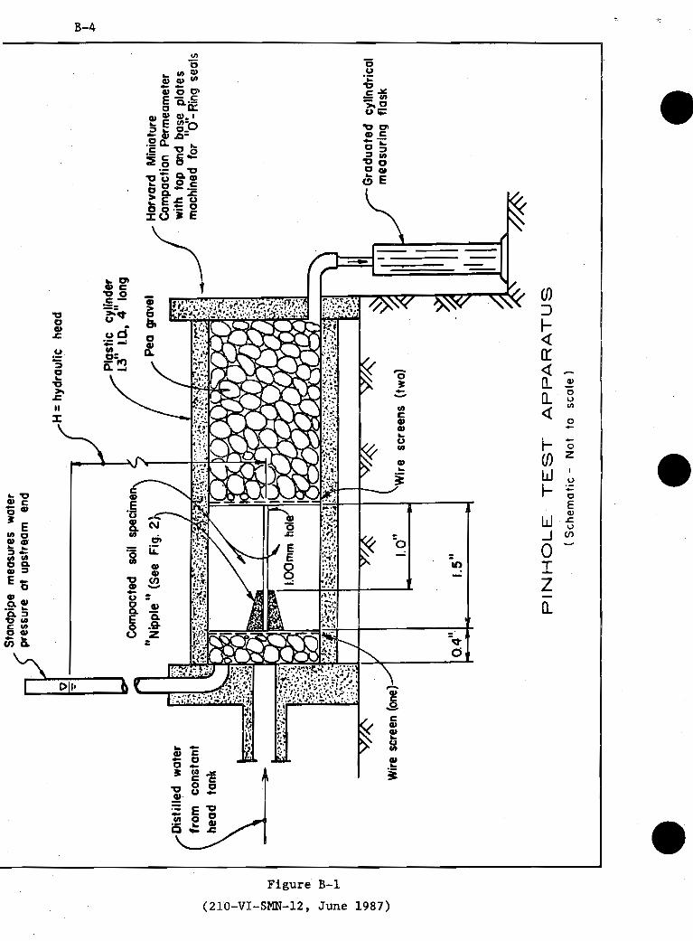
Figure B-1
(210-VI-SMN-12, June 1987)

~ i ~ p l ; ' (truncated cone) machined from plastic or metal with 1.50 millimeter hole
/Z 'lESeOnf 0.4" / drilled in center
screen (14 wires to
0 o" Scole in Inches
SECTION THROUGH PINHOLE TEST SPECIMEN
Figure B-2
(210-VI-SMN-12, June 1987)

PIN HOLE TEST DATA
?in Hole Test No.
;ample No.
Date: Page:
Specimen after t e s t :
%napaction Characteristics 400d $a r er Con t en t n@Qr Wf/hum listilled water added: fl or
Yes No
%ring time: Flow started on IS+ t r i a l .
Color from Side
Remarks
TYPICAL DATA FOR DISPERSIVE CLAY (Dl)
Figure B-3
(210-VI-SMN-12, June 1987)

PIN HOLE TEST DATA
Remarks
Pin Hole Teet No. Date: Page:
Sample No. Specimen after test :
Compae t ion Characteristics s o m ~ h
Water content /9- 3% No e & o ~ / Distilled water added: or o f h / e
Yes No
Curing t i m e : N ~ n e ~ ~ m p ~ & d d f g f d ~ ' U l ~ f e / ~ ~ ~ f e n f low started on t r i a l .
1 50 ( /5 1 I TYPICAL DATA FOR DISPERSIVE CLAY (Dl)
Figure B-4
(210-VI-SMN-12, June 1987)

T A B L E B-1
S U M M A R Y OF C R I T E R I A FOR E V A L U A T I N G R E S U L T S
Class i f i c a t i o n (Table 1)
Tes t Time Visua l F i n a l For Given Flow Through
Head He ad Specimen (Inches) (minutes) (ml/sec)
2 5 > 1.5
a t End of A£ ter Test
Very d i s t i n c t
D i s t i n c t t o s l i g h t
S l i g h t b u t 1 . 5 ~ e a s i l y v i s i b l e
S l i g h t b u t 2x e a s i l y v i s i b l e
Clear o r b a r e l y 2x v i s i b l e
C r y s t a l c l e a r No e ros ion
TABLE B - 2
CATEGORIES OF TEST RESULTS .
Resul t s C l a s s i f i c a t i o n of S o i l
(210-VI-SMN-12, June 1987)
N D 4 and ND3
ND2 and ND1
In te rmedia te s o i l s : erode slowly under 2-inch o r 7-inch head.
Non-dispersive s o i l : no c o l l o i d a l e ros ion under 15-inch o r 40-inch head.