portable particle counters/sensors initial screening tests
TRANSCRIPT
Portable Particle Counters/SensorsInitial Screening Tests
Allison M. TomsMarilyn S. Squalls
Michael PoffJOAP-TSC
85 Millington AvenuePensacola, FL 32508-5010
850-452-JOAPwww.joaptsc.navy.mil
Abstract: The Army AMCOM Hydraulic Contamination Integrated Product Team (IPT) is investigating thepossibility of integrating a portable particle counter or sensor on their Air Ground Portable Units (AGPU).An AGPU is a military version of a portable filter cart used for flushing/cleaning helicopter hydraulicsystems. To ensure the system is clean, a sensor mounted on the AGPU will monitor the cleaning cycle forcompleteness and reliability. In addition, the particle counter internal to the AGPU negates the need to takesamples for laboratory analysis. Flight line conditions have the potential to add contamination while takingsamples.
Any sensor selected for use on the AGPU must be capable of measuring fluid cleanliness at ~65psifrom the return line of the aircraft. Since the hydraulic fluid will have entrained air bubbles, thesensor must also be capable of accurately measuring particulate contamination in the presence of airbubbles. The sensor system can either remove or discount the air bubbles.
The Army IPT requested assistance from the Joint Oil Analysis Program Technical Support Center(JOAP-TSC) for the initial screening of several particle-counting units. For the screening process,the JOAP-TSC recommended three initial tests for the manufacturers. The tests were performed at theJOAP-TSC.
1. Provide documentation that the unit has been calibrated according to and meets ISO11171 Calibration. The Army IPT wants an instrument/sensor with the capability tomeet the ISO 11171 and ISO 4406-1999. Companies were asked to provide docu-mentation that their instrument has passed the required tests for the ISO 11171calibration – verify flow rate, accuracy, coincidence error, sizing calibration,resolution, etc.
2. Analyze Medium Test Dust (MTD) reference fluid five times with aeration under65psi to simulate the air bubbles that will be found in the aircraft to AGPU return line.In addition, MTD reference was analyzed without bubbles (fluid was sonicated) at65psi to demonstrate laboratory conditions. Calculate mean, standard deviation, relativestandard deviation and D
Q.
3. Analyze used hydraulic fluid five times with aeration under 65psi to simulate air bubbles.Calculate mean, standard deviation and relative standard deviation. In addition, the usedfluid was analyzed without aeration under 65psi.
Lubrication & Fluid Power , Nov 2002, Vol 3, Issue 2, Pg 9-12
The JOAP-TSC felt that any manufacturer’s instrument that passes these three screening tests, would be agood candidate for further engineering/practical evaluation by the Army.
The results of the initial screening tests validated the desirability to screen available products for accuracyand suitability prior to procurement.
Key Words: Hydraulic fluid, ISO 11171, JOAP; particle counting, sensors
Instrument Overview: Most particle counters use light or infrared energy to illuminate individual particlesand are referred to as light obscuration particle counters. The amount of light blocked by a particle isdetected by a photodiode and translated into an electric output signal; the frequency and amplitude of theoutput signal provide particle size and concentration information. An integrated flow rate meter measures theflow rate, which is required to determine the cleanliness class.
Testing Results: Several manufacturers demonstrated their product and performed the screening tests.Due to contractor sensitive information, the actual companies tested will not be identified other than byCompany A, B and C.
1. Documentation:• Company A provided the ISO 11171 Calibration documentation after testing. The documentation
included the requested information: tables (and some plots) for coincidence error, accuracy, sizingcalibration, flow rate, resolution and a certificate.
• Company B did not provide the ISO 11171 Calibration documentation. A summary sheet wasprovided after testing. It did not providethe requested information.
• Company C provided the ISO 11171Calibration documentation before testing.The documentation included the requestedinformation: tables (and some plots) forcoincidence error, accuracy, sizingcalibration, flow rate, resolution and acertificate.
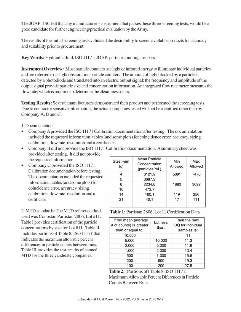
2. MTD standards: The MTD reference fluidused was Conostan Partistan 2806, Lot #11.Table I provides certification of the particleconcentrations by size for Lot #11. Table IIincludes portions of Table 8, ISO 11171 thatindicates the maximum allowable percentdifferences in particle counts between runs.Table III provides the test results of aeratedMTD for the three candidate companies.
If the mean (average # of counts) is greater
than or equal to:
but less than:
Then the max. DQ for individual
samples is:10,000 115,000 10,000 11.32,000 5,000 11.91,000 2,000 13.4500 1,000 15.6200 500 19.3100 200 27.5
Size >um (c)
Mean Particle Concentration (particles/mL)
Min Allowed
Max Allowed
4 6121.9 5091 74705 3687.3 6 2234.6 1880 309210 473.7 14 160.1 119 25621 40.1 17 111
Table 1: Partistan 2806, Lot 11 Certification Data
Table 2: (Portions of) Table 8, ISO 11171,Maximum Allowable Percent Diferences in ParticleCounts Between Runs.
Lubrication & Fluid Power , Nov 2002, Vol 3, Issue 2, Pg 9-12

Table III: Results from testing MTD Reference Fluid. The results in bold fail.*Minimum and Maximum values allowed for reference material
• Company A: The unit accurately evaluated the reference material with and without bubbles and passedD
Q for all test runs. Since the unit passed with bubbles, only one run was performed for the sonicated
(non-aerated) sample, which also passed.• Company B: The unit did not pass ISO standards (D
Q) for the aerated sample (6u and 14u failed) or the
sonicated (non-aerated) sample (14u failed).• Company C: The unit did not pass ISO standards (D
Q) for the aerated sample (4u, 6u and 14u failed)
or the sonicated (non-aerated) sample (4u, 6u and 14u failed).
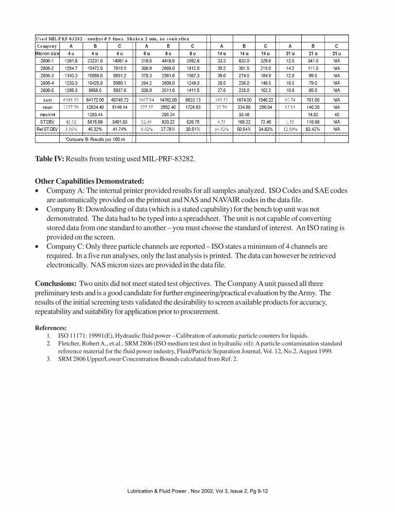
3. Used Fluid (Mil-PRF-83282): The hydraulic fluid used in the helicopters is Mil-PRF-83282. A 2-galloncontainer of used Mil-PRF-83282 was provided by AMCOM IPT from a helicopter under maintenance.Table IV provides the test results of used MIL-PRF-83282 for the three candidate companies.
• Company A: Since the particle counting unit from Company A passed the MTD (with and withoutbubbles); its results were taken as the benchmark for the used oil. The relative standard deviation wasless than 15% for all size ranges (3% for 4u, 10% for 6u, 15% for 14u and 13% for 21u). There wereless than 100 particles for the 14u and 21u size ranges.
• Company B: The values for the Company B unit were within 11% of the benchmark: 0% for 4u, 11%for 6u and 0% for 14u. The relative standard deviation however was 45% for 4u, 28% for 6u, 51% for14u and 83% for 21u. There were less than 100 particles for the 14u and 21u size ranges.
• Company C: The values for the Company C unit were significantly off from the benchmark; 538% for4u, 427% for 6u, and 530% for 14u. The relative standard deviation was 42% for 4u, 31% for 6u and35% for 14u.
Lubrication & Fluid Power , Nov 2002, Vol 3, Issue 2, Pg 9-12
Other Capabilities Demonstrated:• Company A: The internal printer provided results for all samples analyzed. ISO Codes and SAE codes
are automatically provided on the printout and NAS and NAVAIR codes in the data file.• Company B: Downloading of data (which is a stated capability) for the bench top unit was not
demonstrated. The data had to be typed into a spreadsheet. The unit is not capable of convertingstored data from one standard to another – you must choose the standard of interest. An ISO rating isprovided on the screen.
• Company C: Only three particle channels are reported – ISO states a minimum of 4 channels arerequired. In a five run analyses, only the last analysis is printed. The data can however be retrievedelectronically. NAS micron sizes are provided in the data file.
Conclusions: Two units did not meet stated test objectives. The Company A unit passed all threepreliminary tests and is a good candidate for further engineering/practical evaluation by the Army. Theresults of the initial screening tests validated the desirability to screen available products for accuracy,repeatability and suitability for application prior to procurement.
References:1. ISO 11171: 19991(E), Hydraulic fluid power – Calibration of automatic particle counters for liquids.2. Fletcher, Robert A., et.al., SRM 2806 (ISO medium test dust in hydraulic oil): A particle-contamination standard
reference material for the fluid power industry, Fluid/Particle Separation Journal, Vol. 12, No.2, August 1999.3. SRM 2806 Upper/Lower Concentration Bounds calculated from Ref. 2.
Table IV: Results from testing used MIL-PRF-83282.
Lubrication & Fluid Power , Nov 2002, Vol 3, Issue 2, Pg 9-12