portable filter carts -...
TRANSCRIPT
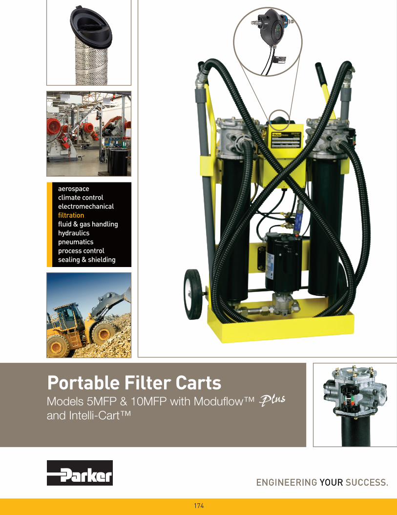
Portable Filter CartsModels 5MFP & 10MFP with Moduflow™and Intelli-Cart™
174
175
• Filteringnewfluidbeforeputtingintoservice
• Transferringfluidfromdrumsorstoragetankstosystemreservoirs
• Conditioningfluidthatisalreadyinuse
• Complimentingexistingsystemfiltration
• Removingfreeandemulsifiedwaterfromasystem
• Forusewithfluidssuchashydraulic,gearandlubeoils
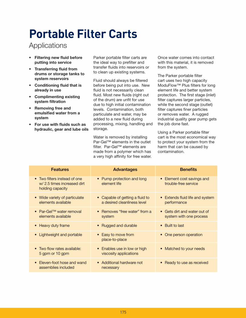
Parker portable filter carts are the ideal way to prefilter and transfer fluids into reservoirs or to clean up existing systems.
Fluid should always be filtered before being put into use. New fluid is not necessarily clean fluid. Most new fluids (right out of the drum) are unfit for use due to high initial contamination levels. Contamination, both particulate and water, may be added to a new fluid during processing, mixing, handling and storage.
Water is removed by installing Par-Gel™ elements in the outlet filter. Par-Gel™ elements are made from a polymer which has a very high affinity for free water.
Once water comes into contact with this material, it is removed from the system.
The Parker portable filter cart uses two high capacity ModuFlow™ Plus filters for long element life and better system protection. The first stage (inlet) filter captures larger particles, while the second stage (outlet) filter captures finer particles or removes water. A rugged industrial quality gear pump gets the job done fast.
Using a Parker portable filter cart is the most economical way to protect your system from the harm that can be caused by contamination.
Features
• Twofiltersinsteadofone w/ 2.5 times increased dirt holding capacity
• Widevarietyofparticulate elements available
• Par-Gel™waterremoval elements available
• Heavydutyframe
• Lightweightandportable
• Twoflowratesavailable: 5 gpm or 10 gpm
• Eleven-foothoseandwand assemblies included
Advantages
• Pumpprotectionandlong element life
• Capableofgettingafluidto a desired cleanliness level
• Removes“freewater”froma system
• Ruggedanddurable
• Easytomovefrom place-to-place
• Enablesuseinloworhigh viscosity applications
• Additionalhardwarenot necessary
Benefits
• Elementcostsavingsand trouble-free service
• Extendsfluidlifeandsystem performance
• Getsdirtandwateroutof system with one process
• Builttolast
• Onepersonoperation
• Matchedtoyourneeds
• Readytouseasreceived
Portable Filter CartsApplications
176
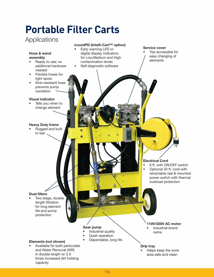
Elements(notshown)• Available for both particulate
andWaterRemoval(WR)in double length w/ 2.5 times increased dirt holding capacity
ElectricalCord• 6 ft. with ON/OFF switch• Optional 20 ft. cord with
retractable reel & mounted power switch with thermal overload protection
Servicecover• Top-accessible for
easy changing of elements
Dualfilters• Two stage, double
length filtration for long element life and pump protection
Hose&wandassembly• Readytouse;no
additional hardware needed
• Flexible hoses for tight spots
• Kink-resistant hose prevents pump cavitation
Gearpump• Industrial quality• Quiet operation• Dependable, long life
Driptray• Helpskeepthework
area safe and clean
Visualindicator• Tells you when to
change element
110V/220VACmotor• Industrial brand
name
HeavyDutyframe• Ruggedandbuilt
to last
icountPD(Intelli-Cart™option)• EarlywarningLEDor
digital display indicators forLow,MediumandHighcontamination levels
• Self diagnostic software
Portable Filter CartsApplications
177
MaximumRecommendedFluidViscosity: 5MFP – 3000 SUS (647cSt) 0.85 specific gravity
10MFP – 500 SUS (108 cSt) 0.85 specific gravity
VisualIndicator(outletfilter): Visual differential type 3-band (clean, change, bypass)
FilterBypassValveSettings(IntegraltoElement): Inlet – 3 psid (0.2 bar) Outlet – 35 psid (2.4 bar)
OperatingTemperature: Sealoption“B”(standard) -40°F to +150°F (-40°C to +66°C)
ElectricalServiceRequired: 5MFP – 110/220 volts, 60/50
Hz,singlephase,8/4amps 10MFP – 110/220 volts, 60/50
Hz,singlephase,10/5amps
ElectricalMotor: 5MFP – ½ hp @ 1725 rpm,
Open, Drip Proof 10MFP – ¾ hp @ 3450 rpm,
Open, Drip Proof Thermal overload protection
Construction: Cart frame – Steel Filter head – Aluminum Filter bowl – Steel Hoses–PVC(Std.) EPDM(hightempoption) Wands – PVC (Std.) Steel tube (high temp
option)
Weight: 110 lbs. (45.4kg)
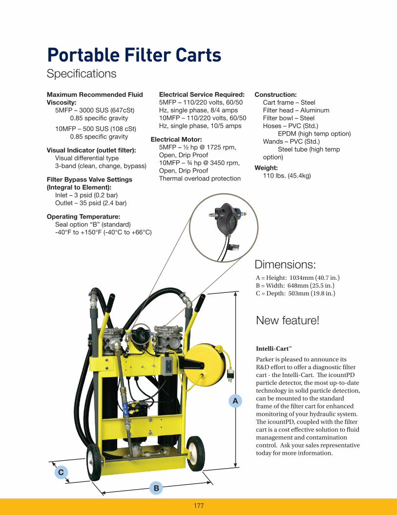
A
Dimensions:A = Height: 1034mm (40.7 in.)B = Width: 648mm (25.5 in.)C = Depth: 503mm (19.8 in.)
B
New feature!
C
Intelli-Cart™
Parker is pleased to announce its R&D effort to offer a diagnostic filter cart - the Intelli-Cart. The icountPD particle detector, the most up-to-date technology in solid particle detection, can be mounted to the standard frame of the filter cart for enhanced monitoring of your hydraulic system. The icountPD, coupled with the filter cart is a cost effective solution to fluid management and contamination control. Ask your sales representative today for more information.
Portable Filter CartsSpecifications
178
Notes:1. Par-Gel™ elements are designed to remove “free wa-
ter”, which is defined as water that is above a particular fluid’s saturation level.
2. Capacity is very dependent on flow rate and viscosity. Not recommended with fluids in excess of 500 SUS.
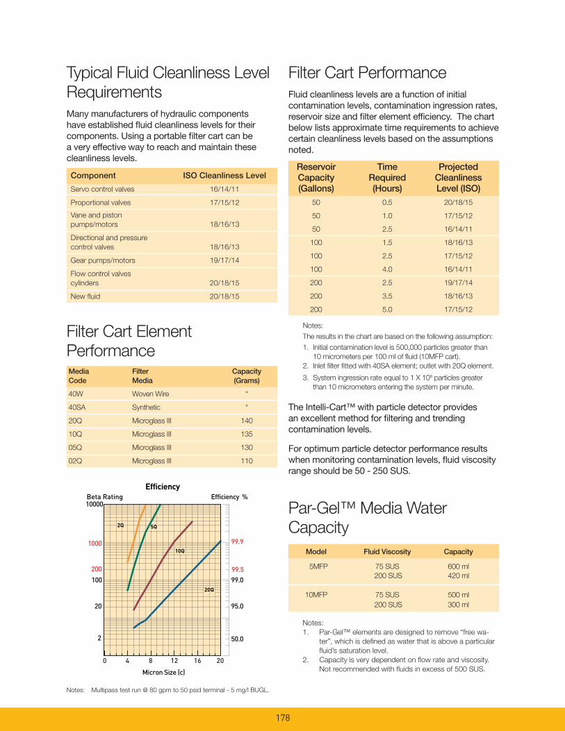
Typical Fluid Cleanliness Level RequirementsMany manufacturers of hydraulic components have established fluid cleanliness levels for their components. Using a portable filter cart can be a very effective way to reach and maintain these cleanliness levels.
Filter Cart PerformanceFluid cleanliness levels are a function of initial contamination levels, contamination ingression rates, reservoirsizeandfilterelementefficiency.Thechartbelow lists approximate time requirements to achieve certain cleanliness levels based on the assumptions noted.
Notes: The results in the chart are based on the following assumption:1. Initial contamination level is 500,000 particles greater than
10 micrometers per 100 ml of fluid (10MFP cart).2. Inlet filter fitted with 40SA element; outlet with 20Q element.
3. System ingression rate equal to 1 X 10⁶ particles greater than 10 micrometers entering the system per minute.
Reservoir Time Projected Capacity Required Cleanliness (Gallons) (Hours) Level (ISO) 50 0.5 20/18/15
50 1.0 17/15/12
50 2.5 16/14/11
100 1.5 18/16/13
100 2.5 17/15/12
100 4.0 16/14/11
200 2.5 19/17/14
200 3.5 18/16/13
200 5.0 17/15/12
Component ISO Cleanliness Level
Servo control valves 16/14/11
Proportional valves 17/15/12
Vane and piston pumps/motors 18/16/13
Directional and pressurecontrol valves 18/16/13
Gear pumps/motors 19/17/14
Flow control valvescylinders 20/18/15
New fluid 20/18/15
Filter Cart Element PerformanceMedia Filter CapacityCode Media (Grams)
40W Woven Wire *
40SA Synthetic *
20Q Microglass III 140
10Q Microglass III 135
05Q Microglass III 130
02Q Microglass III 110
Notes: Multipass test run @ 80 gpm to 50 psid terminal - 5 mg/l BUGL.
Model Fluid Viscosity Capacity 5MFP 75 SUS 600 ml 200 SUS 420 ml 10MFP 75 SUS 500 ml 200 SUS 300 ml
Par-Gel™ Media Water Capacity
Efficiency %Efficiency
Beta Rating
1000
10000
99.9
99.599.0100
200
20
2 50.0
95.0
Micron Size (c)
2Q
10Q
20Q
5Q
0 4 8 12 16 20
The Intelli-Cart™ with particle detector provides an excellent method for filtering and trending contamination levels.
For optimum particle detector performance results when monitoring contamination levels, fluid viscosity range should be 50 - 250 SUS.
179
2. Removetubewandsfromoiltoprevent siphoning.
3. Loosenhexheadscrewsonfiltercover. Turn cover to clear screws, remove cover.
4. Pull filter element from the filter head.
a)ReplacethesyntheticorMicroglass III elements. Verify correct element replacement.
b) Wire mesh elements can be cleaned. Ultrasonic cleaners provide best results.
5. Install element in filter housing. Make sure element o-rings seat properly into the head, making sure that the notch on the element lines up with the notch in the head.
6. Inspect the cover o-ring and replace if necessary.
7. Replacecoverandtightenhexhead screws until they are snug. Do not over-torque (16 - 19 Ft.Lbs.)thesescrews.Donotinterchange the inlet filter cover with the outlet filter cover. (The inletfilterhasa“RFP”prefix,theoutletfilterhasa“ILP”prefix).
8. ContacttheHFDservicedepartment at 419-644-0259 regarding iPD calibration.
9. iPDremoval:removeoillinesfromthe iPD at the two fittings closest to the iPD. Disconnect the two cablesfromtheiPD.RemoveiPDfrom cart via two screws. The cart can be used without the iPD as long as the sample hoses are removed from the System 20. Protect sampling connectors from contamination.
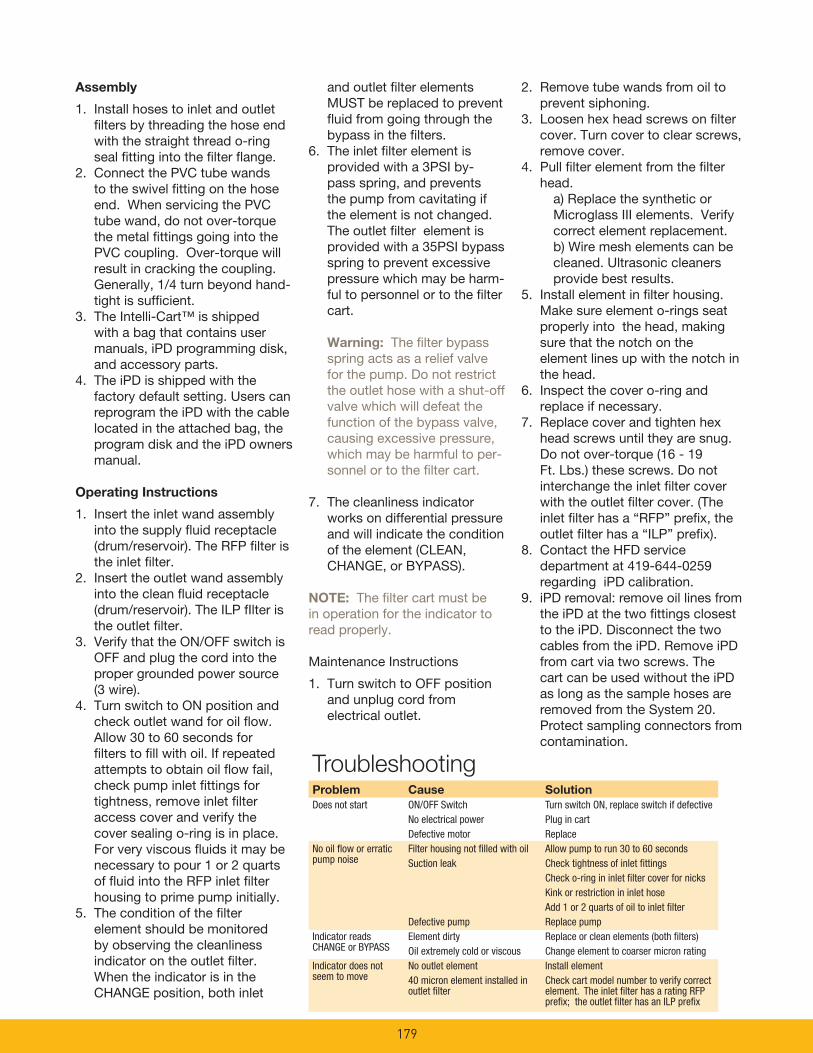
Assembly
1. Install hoses to inlet and outlet filters by threading the hose end with the straight thread o-ring seal fitting into the filter flange.
2. Connect the PVC tube wands to the swivel fitting on the hose end. When servicing the PVC tube wand, do not over-torque the metal fittings going into the PVC coupling. Over-torque will result in cracking the coupling. Generally, 1/4 turn beyond hand-tight is sufficient.
3. The Intelli-Cart™ is shipped with a bag that contains user manuals, iPD programming disk, and accessory parts.
4. The iPD is shipped with the factory default setting. Users can reprogram the iPD with the cable located in the attached bag, the program disk and the iPD owners manual.
OperatingInstructions
1. Insert the inlet wand assembly into the supply fluid receptacle (drum/reservoir).TheRFPfilteristhe inlet filter.
2. Insert the outlet wand assembly into the clean fluid receptacle (drum/reservoir).TheILPfIlteristhe outlet filter.
3. Verify that the ON/OFF switch is OFF and plug the cord into the proper grounded power source (3 wire).
4. Turn switch to ON position and check outlet wand for oil flow. Allow 30 to 60 seconds for filters to fill with oil. If repeated attempts to obtain oil flow fail, check pump inlet fittings for tightness, remove inlet filter access cover and verify the cover sealing o-ring is in place. For very viscous fluids it may be necessary to pour 1 or 2 quarts offluidintotheRFPinletfilterhousing to prime pump initially.
5. The condition of the filter element should be monitored by observing the cleanliness indicator on the outlet filter. When the indicator is in the CHANGEposition,bothinlet
and outlet filter elements MUST be replaced to prevent fluid from going through the bypass in the filters.
6. The inlet filter element is provided with a 3PSI by-pass spring, and prevents the pump from cavitating if the element is not changed. The outlet filter element is provided with a 35PSI bypass spring to prevent excessive pressure which may be harm-ful to personnel or to the filter cart. Warning: The filter bypass spring acts as a relief valve for the pump. Do not restrict the outlet hose with a shut-off valve which will defeat the function of the bypass valve, causing excessive pressure, which may be harmful to per-sonnel or to the filter cart.
7. The cleanliness indicator works on differential pressure and will indicate the condition oftheelement(CLEAN,CHANGE,orBYPASS).
NOTE: The filter cart must be in operation for the indicator to read properly.
Maintenance Instructions
1. Turn switch to OFF position and unplug cord from electrical outlet.
TroubleshootingProblem Cause SolutionDoes not start ON/OFF Switch Turn switch ON, replace switch if defective No electrical power Plug in cart Defective motor ReplaceNo oil flow or erratic Filter housing not filled with oil Allow pump to run 30 to 60 secondspump noise Suction leak Check tightness of inlet fittings Check o-ring in inlet filter cover for nicks Kink or restriction in inlet hose Add 1 or 2 quarts of oil to inlet filter Defective pump Replace pumpIndicator reads Element dirty Replace or clean elements (both filters)CHANGE or BYPASS Oil extremely cold or viscous Change element to coarser micron ratingIndicator does not No outlet element Install elementseem to move 40 micron element installed in Check cart model number to verify correct outlet filter element. The inlet filter has a rating RFP prefix; the outlet filter has an ILP prefix
180
Item No.
Part No. Description Qty
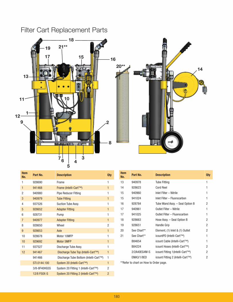
1 928690 Frame 1
1 941468 Frame (Intelli-Cart™) 1
2 940980 Pipe Reducer Fitting 1
3 940979 Tube Fitting 1
4 937526 Suction Tube Assy. 1
5 928652 Adapter Fitting 1
6 928731 Pump 1
7 940977 Adapter Fitting 1
8 928650 Wheel 2
9 928653 Axle 1
10 928678 Motor 10MFP 1
10 929692 Motor 5MFP 1
11 937527 Discharge Tube Assy. 1
12 941467 Discharge Tube Top (Intelli-Cart™) 1
941466 Discharge Tube Bottom (Intelli-Cart™) 1
STI.0144.100 System 20 (Intelli-Cart™) 1
3/8-8F40HG5S System 20 Fitting 1 (Intelli-Cart™) 2
12/8 F50X-S System 20 Fitting 2 (Intelli-Cart™) 2
Item No.
Part No. Description Qty
13 940978 Tube Fitting 1
14 928623 Cord Reel 1
15 940960 Inlet Filter – Nitrile 1
15 941024 Inlet Filter – Fluorocarbon 1
16 928784 Tube Wand Assy. – Seal Option B 2
17 940961 Outlet Filter – Nitrile 1
17 941025 Outlet Filter – Fluorocarbon 1
18 928663 Hose Assy. – Seal Option B 2
19 928651 Handle Grip 2
20 See Chart** Element, (1) Inlet & (1) Outlet 2
21 See Chart** icountPD (Intelli-Cart™) 1
B84654 icount Cable (Intelli-Cart™) 1
B84224 icount Hoses (Intelli-Cart™) 2
2/2A40EG4M-S icount Fitting 1(Intelli-Cart™) 2
EMA3/1/8ED icount Fitting 2 (Intelli-Cart™) 2
**Refer to chart on How to Order page.
5
1517
14
8
1
10
2
11
13
6
18
16
9
20**
34
7
19
Filter Cart Replacement Parts
21**
12
181
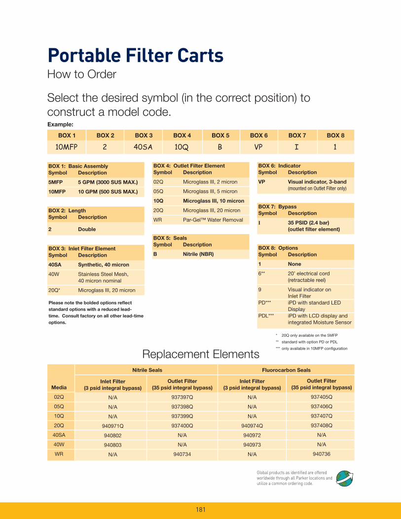
BOX2:LengthSymbol Description
2 Double
BOX6:IndicatorSymbol Description
VP Visualindicator,3-band (mounted on Outlet Filter only)
BOX7:BypassSymbol Description
I 35PSID(2.4bar) (outletfilterelement)
BOX1 BOX2 BOX3 BOX4 BOX5 BOX6 BOX7 BOX8
10MFP 2 40SA 10Q B VP I 1
BOX1:BasicAssemblySymbol Description
5MFP 5GPM(3000SUSMAX.)
10MFP 10GPM(500SUSMAX.)
BOX3:InletFilterElementSymbol Description
40SA Synthetic,40micron
40W Stainless Steel Mesh, 40 micron nominal
20Q* Microglass III, 20 micron
BOX4:OutletFilterElementSymbol Description
02Q Microglass III, 2 micron
05Q Microglass III, 5 micron
10Q MicroglassIII,10micron
20Q Microglass III, 20 micron
WR Par-Gel™WaterRemoval
BOX5:SealsSymbol Description
B Nitrile(NBR)BOX8:OptionsSymbol Description
1 None
6** 20’ electrical cord (retractable reel)
9 Visual indicator on Inlet FilterPD*** iPDwithstandardLED DisplayPDL*** iPDwithLCDdisplayand integrated Moisture Sensor
Media
02Q
05Q
10Q
20Q
40SA
40W
WR
InletFilter(3psidintegralbypass)
N/A
N/A
N/A
940971Q
940802
940803
N/A
OutletFilter(35psidintegralbypass)
937397Q
937398Q
937399Q
937400Q
N/A
N/A
940734
InletFilter(3psidintegralbypass)
N/A
N/A
N/A
940974Q
940972
940973
N/A
OutletFilter(35psidintegralbypass)
937405Q
937406Q
937407Q
937408Q
N/A
N/A
940736
NitrileSeals FluorocarbonSeals
Replacement Elements
Pleasenotetheboldedoptionsreflectstandardoptionswithareducedlead-time.Consultfactoryonallotherlead-timeoptions.
Example:
Select the desired symbol (in the correct position) to construct a model code.
* 20Q only available on the 5MFP
** standardwithoptionPDorPDL
*** only available in 10MFP configuration
Portable Filter CartsHow to Order
Global products as identified are offered worldwide through all Parker locations and utilize a common ordering code.