pore evolution during high pressure atomic vapor deposition
TRANSCRIPT

Pore evolution during high pressure atomic vapor deposition
D. D. HassÆ Y. Y. Yang Æ H. N. G. Wadley
Published online: 31 January 2009
� Springer Science+Business Media, LLC 2009
Abstract The development of physical vapor deposition
systems that employ inert gas jets to entrain and deposit
atomic and molecular fluxes have created an interest in the
atomic assembly of thin films under high pressure (10–
500 Pa) deposition conditions. Thin films grown under
elevated pressure and low surface mobility conditions can
contain a higher volume fraction of porosity and a different
pore morphology to coatings created by conventional, low
pressure (\10-4 Pa) deposition processes. A recent direct
simulation Monte Carlo simulation analysis of binary
vapor–gas jet atom interactions has shown that the incident
angle distribution (IAD) for vapor atom impacts with a
substrate is strongly effected by the background pressure.
Here, these results are combined with a kinetic Monte
Carlo technique to simulate the high pressure growth of
vapor deposited nickel films and identify the mechanisms
of pore formation. We find that when the surface atom
mobility is low, shadowing of oblique angle arrivals by
features on the substrate result in the incorporation of
porosity with a hierarchical size distribution that includes
elongated, inter-columnar pores and finer scale intra-
columnar pores. The nucleation of the inter-columnar pores
is related not only to the IAD, but also to the height and
spacing of the initial asperities on the substrate and to those
that subsequently evolve during deposition. The volume
fraction of the inter-columnar pores is found to increase as
both the fraction of oblique atom arrivals and the height of
the asperities increase. For each prescribed IAD and
asperity height, an asperity spacing is found that maximizes
the inter-columnar pore fraction. By varying the IAD for a
given substrate surface topology, in conjunction with
intermittent observations of the coating structure during the
growth process, the flux shadowing mechanisms that gov-
ern the inter-columnar pore nucleation have been
determined.
Keywords Physical vapor deposition (PVD) �Computer simulation � Coatings
1 Introduction
Physical vapor deposited coatings containing controlled
pore volume fractions and morphologies are utilized for
many applications including thermal barrier coatings [1, 2],
the anodes and cathodes of solid oxide fuels cells [3], in
batteries [4] and numerous other optical, medical, chemical
and biological applications [5–7]. Porosity is incorporated
in these coatings to manipulate their properties. For
instance, the yttria stabilized zirconia (YSZ) coatings used
for the thermal protection of gas turbine engine compo-
nents contain large (micron size) inter-columnar pores
aligned perpendicular to the substrate surface that are uti-
lized to increase the in-plane compliance of the coating.
Smaller, intra-columnar pores are also exploited to reduce
the thermal conductivity of the coating by interrupting the
conductive and radiative mechanisms of thermal transport
[8]. The performance of these porous coatings is governed
by the size, volume fraction and inclination of the pores [9–
11].
Porosity is entrained in vapor deposited coatings when
the surface atoms are unable able to diffuse from their
impact positions on a surface to vacant, low energy lattice
sites, Fig. 1. The adatom surface mobility is effected by
D. D. Hass � Y. Y. Yang � H. N. G. Wadley (&)
Department of Materials Science and Engineering, School of
Engineering and Applied Science, University of Virginia,
Charlottesville, VA 22903, USA
e-mail: [email protected]
123
J Porous Mater (2010) 17:27–38
DOI 10.1007/s10934-008-9261-4
several properties of the vapor flux; the vapor atom’s
translation energy [12], its latent heat of condensation [13]
or heat of reaction with the surface [14], and by the flux of
energetic, assisting ions that sometimes accompany the
condensing atoms [15]. It also depends upon properties of
the substrate such as its temperature [16], and surface
topology [17]. The coatings lattice cohesive energy estab-
lishes the magnitude of the energy barriers impeding
surface migration and thus the thermal or ion impact
energy required to overcome them [13].
Pores are entrained when the surface atom jump fre-
quency is too low to allow complete migration to unfilled
lattice sites before jumping atoms are covered by new
atoms. The jump frequency can be approximated by an
Arrhenius equation of the form, t = toexp(-Q/jT), where
t is the jump frequency, to is the jump attempt frequency,
Q is the activation energy, j is Boltzmann’s constant and T
is the absolute temperature of the solid.
Columnar porosity in a vapor deposited coating is cre-
ated when; (a) the adatom surface mobility is low and (b)
incident vapor atoms are shadowed by features on the
growth surface resulting in flux depleted regions on the
substrate. Columnar voids then become entrained between
local high spots on the surface [18]. The local high spots
themselves are often rough and so under some conditions
the process of void entrainment is simultaneously perpet-
uated at many length scales resulting in a hierarchical pore
topology and a coating surface that has fractal-like form
[19]. Pores ranging from elongated, micron-scaled inter-
columnar pores to nanometer-scaled intra-columnar
porosity then result.
Shadowing of the incident atoms is more likely when
atoms arrive at oblique angles to a surface. These oblique
atom arrivals are ‘‘shadowed’’ by surface asperities or
atomistic irregularities on the surface of the growing film.
These can form, even on initially smooth surfaces, by
variations in the growth rate of differently orientated grains
whose growth rate is crystal orientation dependent [20]. If
the reduced local vapor flux in the shadowed region cannot
be fully compensated by surface diffusion, these regions
eventually become pores. The interplay between the dis-
tribution of adatom’s deposited on the growth surface and
the distance of adatom diffusion determines both the vol-
ume fraction and morphology of pores in a coating.
The incident angle distribution (IAD) of an atomic flux
has a significant effect upon both the pore volume fraction
and morphology, and its manipulation has been used to
control pore morphology. Techniques have included the
use of substrate inclination variation such as tilting or
rotating [5, 11, 21, 22] and methods that exploit vapor
atom–background gas atom collisions. Gas jet enhanced
deposition in a high pressure environment is an example of
the latter approach [23]. In all cases, these techniques alter
the IAD at the substrate which in turn modifies flux
shadowing.
Inert gas jet assisted methods of vapor deposition [24]
enable control of the IAD provided the pressure is suffi-
ciently high (typically [ 5 Pa) that the mean free path
between vapor atom–inert gas atom collisions is significantly
less than the evaporation source-to-substrate distance. This
results in many binary collisions between the vapor atoms
and the atoms in the gas jet. Recent results for the deposition
of yttria stabilized zirconia onto nickel substrates using an
EB-DVD process operating at high pressures indicate that
the pore topology can be manipulated over wide ranges by
modifying the gas jet conditions [25]. Figure 2 shows an
Fig. 1 Pores can form because of flux shadowing by local asperities
on the growth surface. Surface diffusion can transport material into
shadowed regions. The diffusion rate on the surface is controlled by
the material type/local atom configuration dependent activation
barriers for hopping and by the substrate temperature
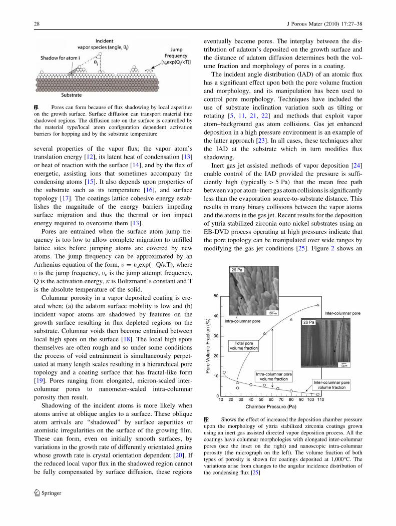
Fig. 2 Shows the effect of increased the deposition chamber pressure
upon the morphology of yttria stabilized zirconia coatings grown
using an inert gas assisted directed vapor deposition process. All the
coatings have columnar morphologies with elongated inter-columnar
pores (see the inset on the right) and nanoscopic intra-columnar
porosity (the micrograph on the left). The volume fraction of both
types of porosity is shown for coatings deposited at 1,000�C. The
variations arise from changes to the angular incidence distribution of
the condensing flux [25]
28 J Porous Mater (2010) 17:27–38
123

example where the total pore fraction and its components all
depend strongly on the background pressure.
The effects of background pressure upon the IAD during
deposition in gas jet assisted deposition processes have
recently been characterized using a Direct Simulation
Monte Carlo (DSMC) approach [25, 26]. It was shown that
high pressures increase the width of the incidence angle
distribution (Pw) while increases in gas jet velocities results
in a shift in the median impact angle (hm) away from the
substrate normal that alters the shadowing mechanisms that
control pore formation. In addition to the IAD changes, it
was also shown that, as the deposition pressure increases,
gas phase collisions multiply leading to the vapor phase
nucleation and growth of clusters of atoms. The ‘‘cluster’’
component of the flux is not as strongly scattered by
background atoms and arrives at near normal incidence
angles. The inter-columnar pore width has been found to
track the increase on IAD as pressure is increased, Fig. 3,
until the transition from an atomic to cluster mode of
deposition occurs [25].
Here, we explore the effects of pressure upon the pore
morphology in the cluster-free limit. The relationships
between changes in the IAD and porosity are studied using
a kinetic Monte Carlo (KMC) simulation technique. Using
2D estimates for the surface diffusion energy barriers of
nickel we use the KMC method to simulate the growth of
coatings for a range of incidence angle distributions. This
then enables a systematic investigation of the role of
process pressure (via the IAD reported in [25]) upon pore
evolution during vapor deposition under diffusion con-
strained conditions.
2 Kinetic Monte Carlo modeling
Simulating atomic assembly during the condensation of a
vapor is extremely complicated, even for the mono-
atomic deposition of a close packing metal species such
as nickel. This complexity arises from the many surface
and bulk diffusion pathways (each with a different energy
barrier) available for atomic reassembly during growth.
Further complexity is introduced by the surface topogra-
phy which dynamically evolves. This causes the
significance of flux shadowing to also evolve during
coating growth. Under high deposition rate conditions,
these changes in local flux also modify the local
‘‘equivalent’’ surface temperature (and hence surface atom
mobility) because of the associated latent heat of con-
densation release.
Many approaches are being explored for the atomic
scale simulation porous film growth [27]. Here, a relatively
simple kinetic Monte Carlo (KMC) simulation approach
has been employed to link the flux incident upon a surface
to the resulting film morphology [28]. In a kinetic Monte
Carlo simulation, particles (atoms) are added to an evolv-
ing topography surface and their subsequent assembly (by
atomic hopping) is simulated by assuming a thermally
activated jumping process. In principle, the approach is
simple; the probability of thermally activated hopping for
every atom in an ensemble is calculated and one is ran-
domly selected. The inverse of its probability yields a time
between two hops which is subtracted from the mean time
between atom arrivals on the surface. Hops are allowed to
continue (and the surface topography to change) until the
time between consecutive atom arrivals is consumed
whereupon the new atom is deposited and the process
repeats.
In practice the multiplicity of hopping paths (each with
its own activation barrier) creates a complex, computa-
tionally significant problem to solve. Great simplification
is achieved by resorting to a 2D approximation and is
used here. The activation barriers in a 2D approximation
lose much of their quantitative significance, but key dif-
ferences are maintained so that the competition between
the various assembly mechanisms remains (see reference
[27] for a detailed discussion). The kinetic Monte Carlo
method used here utilizes this multi-path diffusion anal-
ysis to determine the surface topography and the
evolution of the coatings interior atomic structure. It
effectively captures many of the key phenomena during
Fig. 3 Shows both the measured width of the inter-columnar pores
for YSZ coatings deposited at 1,000�C and the breadth (Pw) of the
simulated IAD distribution as a function of the chamber pressure.
Note that a good correlation exists between these parameters until
very high pressures are reached where cluster deposition then
becomes prevalent
J Porous Mater (2010) 17:27–38 29
123

thin film growth including the role of the Ehrlich-
Schwoebel barrier which is critical for a realistic treat-
ment of the competition between step-flow (terrace) [29]
and island modes of growth [30]. Individual atom jump
rates are taken to depend upon a local, configuration
dependent activation barrier which is pre-computed using
a molecular statics approach [31]. The calculated activa-
tion energies for several different configurational
transitions in nickel are given in Table 1. The approach
includes a treatment of the latent heat of condensation
release and its effect upon local mobility [13].
3 Implementation
The input parameters required for the simulations are
shown in Table 2. The code allowed the IAD to be pre-
scribed by a cosn(h) distribution where h is the angle
between the substrate normal and the incidence direction of
the atom. A typical IAD is shown in Fig. 4. Symmetrical
Table 1 Calculated activation energies for different configurational
transitions in nickel
Table 2 Simulation conditions used for KMC study
Atom type Nickel
Simulated atoms 250,000
T/Tm 0.22
Deposition rate (lm/min) 0.30
Activation barrier [surface jump](eV) 0.472
Activation barrier [Schwoebel jumps] s1 = 1.090, s2 = 0.706 eV
Fig. 4 A schematic illustration showing the simulation setup
employed. A 2.0 lm wide substrate was used. The substrate
temperature, substrate roughness (in the form of asperities described
by a height, h, and a spacing, s), and IAD were all systematically
varied
30 J Porous Mater (2010) 17:27–38
123

distributions defined by the peak width at half maximum,
Pw, and a peak maximum angle, hm, were used in all cases.
The peak width was controlled by the parameter, n, in the
cosine distribution and the position of a peak maximum
angle in the IAD could be altered by tilting the substrate,
Table 3.
In many applications, porous coatings are deposited onto
substrates that are not atomically smooth. Shadowing of the
flux by an initially rough surface was therefore included in
the analysis. This roughness was introduced in the form of
truncated triangular asperities. The effect of varying the
height, h, spacing, s, and degree of truncation of the
asperities was studied using substrates of a fixed width
(1.8 lm) and periodic lateral boundary conditions. The
deposition rate was 3.0 lm/min and the substrate temper-
ature was T/Tm = 0.22 (here T is the absolute substrate
temperature and Tm is the absolute melting point of nickel).
This temperature was chosen for the 2D simulation since it
resulted in a similar level of atomic assembly between
atom arrivals to that observed in the experiments.
4 Results
4.1 Coating morphology
The morphologies of the simulated nickel films using an
IAD described by Pw = 75� and hm = 0� and a substrate
temperature of T/Tm = 0.22 are shown in Fig. 5. When
deposited onto an atomistically smooth substrate a porous
morphology without columnar pores resulted, Fig. 5a.
Columnar pores occurred when surface asperities with
height, h, and spacing, s, equal to 125 nm were present on
the substrate, Fig. 5b. At least two scales of porosity could
be observed in these coatings, the elongated inter-columnar
pores (that nucleated in the trough regions created between
surface asperities) and finer scaled intra-columnar porosity
that was sometimes also elongated. In Fig. 5c, the width of
the IAD, Pw was increased to 150� and the asperities were
removed. This resulted in the formation of a columnar
morphology with distinct inter-columnar pores (similar to
the case shown in Fig. 5b). These simulations indicate that
columnar porosity develops on rough surfaces even for
relatively narrow vapor atom incidence angle distributions
and just above the surfaces of smooth substrates when the
distribution is broad. Surface roughness was also observed
to develop naturally during the growth process. For a fixed
initial surface roughness and incidence angle distribution
the pore fraction increased with the thickness of the coat-
ing. To untangle the interrelationships between the
properties of the surface and those of the incident flux we
conducted a series of simulations where each variable was
varied independently.
4.2 Adatom angle of incidence
4.2.1 Peak distribution width, Pw
KMC simulations were performed using IAD’s with peak
widths from 35� to 150�. For these simulations h and s were
125 nm and hm was 0�. The coating morphologies are
shown in Fig. 6. When Pw was low (35�) no inter-columnar
pores were observed to form, however, at higher Pw values
(75�–150�) distinct inter-columnar pores were seen. These
pores initiated in the troughs between surface asperities.
The pore fraction increased with Pw, Fig. 7. The inclination
angle of these pores remained constant as did the volume
fraction of the intra-columnar porosity.
4.2.2 Distribution angle at peak maximum, hm
Variations in the angle at peak maximum were studied by
altering hm from 0� to 45�, Fig. 8. For these simulations h
and s were 125 nm and Pw was 120o. In all the simulations
inter-columnar pores were initiated in the troughs of the
substrate. As hm increased (i.e. as the flux became less
normal to the substrate) the inclination of the pores
increased, Fig. 9a. The inclination angle of the pores
directly correlates with the peak maximum angle. In this
case, the pore inclination angle was proportional to the
incidence angle maximum and not its tangent. Thus, when
a broad angular flux distribution exists the tangent rule for
pore inclination [32] is not followed. The pore volume also
increased as hm was increased, Fig. 9b. However, this
Table 3 Experimental design (variation in model parameters for KMC simulations)
Parameter
altered
Peak distribution
width, Pw (�)
Peak maximum
angle hm (�)
Asperity height,
h (lm)
Asperity height,
s (lm)
Substrate temperature
(T/Tm)
Pw 35–150 0 0.125 0.125 0.22
hm 75 0–40 0.175 0.125 0.22
h 120 0 0.0–0.21 0.125 0.22
s 80 0 0.066 0.125–0.750 0.22
J Porous Mater (2010) 17:27–38 31
123

Fig. 5 KMC simulations of nickel growth onto a an atomically
smooth substrate and b a substrate having surface asperities. In these
cases the IAD was defined by Pw = 75� and hm = 0�. The substrate
temperature was T/Tm = 0.22. Note the formation of inter-columnar
pores in b that nucleated at the trough formed by two closely spaced
asperities. Also shown is the intra-porosity that exists in these
coatings. In c inter-columnar pores are shown to form on an
atomically smooth substrate as Pw is increased to 150�
Fig. 6 KMC simulations of nickel growth showing the effect of Pw
on the coating morphology. Note that as the Pw was increased from
35� to 150� the inter-columnar porosity became more prevalent
32 J Porous Mater (2010) 17:27–38
123

increase was entirely made up of inter-columnar pore
volume increases. The intra-columnar pore volume was
unaffected by hm.
4.2.3 Substrate geometry
Asperity height: The role of asperity height, h, was sys-
tematically investigated by increasing h from 25 to 150 nm
while holding the spacing, s, (125 nm) and incidence angle
distribution Pw = 120�, hm = 0�) constant, Fig. 10. The
shape of the asperities was maintained so that the width of
the asperities also increased with the height. Note that no
inter-columnar pores are formed for the smallest asperity
height (25 nm). However, as the asperity height was
increased, inter-columnar pores began to form and became
increasingly prevalent, Fig. 11. Since, the modeled sub-
strate had a fixed width, increasing the asperity width (with
a constant asperity spacing) resulted in a change in the
number of ‘‘peaks and valleys’’ in the modeled region.
Since the inter-columnar pores are observed to nucleate in
the valleys, the inter-columnar pore volume is related to the
number of pore nucleation sites on the substrate. To
account for this change, the average volumes of each
individual inter-columnar pore was calculated and this is
plotted against the asperity height in Fig. 11. The pore
volume fraction was found to be a very strong function of
the pre-existing asperity height.
Fig. 7 A plot showing the dependence of the inter-columnar and total
pore volume fractions upon Pw. The shaded area corresponds to a
region where no inter-columnar pores were observed. The intra-
columnar pore volume fraction increased with Pw beyond this region.
The intra-columnar pore volume fraction (which is the difference
between the total and inter-columnar pore volume) remained constant
with increase in Pw
Fig. 8 KMC simulations of nickel growth showing the effect of hm
on the coating morphology. As hm increased from 0� to 40� the inter-
columnar porosity became more prevalent and the inclination angle of
the pores increased away from the substrate normal
J Porous Mater (2010) 17:27–38 33
123

Asperity spacing: The effect of the spacing, s, between
surface asperities was systematically investigated by
increasing s from 125 to 750 nm while holding the asperity
height (67 nm) and the IAD distribution (Pw = 75�,
hm = 0�) constant. The simulations are shown in Fig. 12.
These simulations indicate that inter-columnar pore for-
mation was strongly affected by the asperity spacing. Since
the number of pore nucleation sites also varied in this case,
the average volume of each inter-columnar pore was cal-
culated and is plotted against the asperity spacing in
Fig. 9 Plots showing the change in a the inter-columnar pore
inclination angle and b the inter-columnar and total pore volume
fraction as hm was varied. Note the both parameters systematically
increased as hm was increased while the intra-columnar pore volume
fraction remained constant. The solid lines are best fits to the data
Fig. 10 Increasing the asperity height from 0.025 to 0.150 lm
resulted in an increased average pore width
34 J Porous Mater (2010) 17:27–38
123

Fig. 13. The results reveal a systematic increase in inter-
columnar pore volume as the spacing is initially increased.
This trend continues until a critical spacing is reached
whereupon the inter-columnar pore volume then decreased
rapidly. Clearly an optimal spacing for nucleating inter-
columnar porosity exists.
5 Pore evolution
The simulations conducted above have indicated that inter-
columnar pores initiate in the valleys between adjacent
surface asperities provided; (i) the substrate temperature is
sufficiently low to inhibit surface diffusion of the deposited
atoms and (ii) the incidence angle distribution is suffi-
ciently broad that a large fraction of oblique atom arrivals
are shadowed. When these criteria are achieved, inter-
columnar pores are formed and perpetuated through the
coating thickness.
To explore how the porosity evolves during the depo-
sition of a thin film, simulations were interrupted during
the film growth. For these analyses, the incidence angle
distribution was defined by Pw = 120� and hm = 0�. The
substrate had asperities 125 nm in height and 125 nm
apart. The substrate temperature T/Tm = 0.22. A typical
result is shown in Fig. 14. It can be seen that after depo-
sition of all atoms, Fig. 14a, the deposited film directly
over the asperities is significantly higher than that above
the initial valley regions. This occurs because the initial
asperity peaks ‘‘shadow’’ the oblique component of the flux
allowing a larger fraction of the atoms to be deposited on
Fig. 11 Plots showing the increase in the inter-columnar pore
volume fraction with asperity height
Fig. 12 KMC simulations showing the effect of increasing the
asperity spacing from 0.25 to 0.625 lm on the coating morphology.
Inter-columnar pores are not observed for asperity spacing’s greater
than 0.375 lm
J Porous Mater (2010) 17:27–38 35
123

hilltops. This is facilitated by a broad angular flux distri-
bution. As growth continues, the peaks of the faster
growing columns, Fig. 14b, further decrease the vapor flux
incident on the columns growing in the troughs. Eventually
a pore is formed above the trough as the vapor flux is
almost completely depleted in this region of the substrate,
Fig. 14c and d.
The ratio of atoms deposited on column peaks to trough
bottoms as a function of the number of atoms deposited for
three incidence angle distribution widths (Pw = 75, 90,
120�) shown in Fig. 15. It can be seen that the flux fraction
in the trough region decreases fastest for the Pw = 120�case where the fraction of oblique adatom arrivals is the
greatest. The pore volume is also the largest when Pw is the
broadest and systematically decreases to zero when the flux
is collimated, Fig. 7.
6 Discussion
The results above show that the morphology of vapor
deposited coatings created under low adatom mobility is
controlled by flux shadowing. This promotes the formation
of columnar morphologies with elongated, inter-columnar
pores. The volume and inclination of these pores are
determined by the angular distribution of the flux and the
surface topology. Valleys between asperities on the growth
surface are the nucleation sites for pores. In these regions
the flux of oblique adatom arrivals is depleted which
Fig. 13 The plot shows the effects of changing the asperity spacing
upon the inter-columnar pore volume fraction. Note that the pore
volume reached a maximum at an intermediate value as the spacing
was increased. Further increases past this intermediate value resulted
in a reduced the pore volume
Fig. 14 KMC simulations of nickel growth onto a substrate having
surface asperities. Results are shown after a 25,000 atoms, b 50,000
atoms, c 75,000 atoms and d 100,000 atoms have been deposited.
Note that the asperities result in variations in the vapor flux
distribution that result in inter-columnar pore formation
36 J Porous Mater (2010) 17:27–38
123

locally reduces the film growth rate. A faster than average
growth rate in the non-shadowed regions further enhances
shadowing. This eventually leads to the formation of an
inter-columnar pore. IAD’s that result in a high fraction of
oblique adatom arrivals (large Pw or hm value) promote
pore formation and also increase the volume of the inter-
columnar pores. As growth progresses, the column peaks
become higher and the area that is flux depleted increases
resulting in an increase in porosity with coating thickness.
The pore content of the coating was observed to exhibit
a maximum at a critical inter-asperity spacing, Sc. This can
be understood by considering Fig. 16 where the spacing of
a pair of asperities on a surface is varied as a flux, fo,
impinges at either ±60� to the surface normal. Flux
shadowing of one or the other sources occurs near the
asperities (the lightly shaded regions in Fig. 16a. When the
inter-asperity spacing is small, Fig. 16a, the shadowed
regions can overlap in the trough. In the shadow overlap
region the flux is zero. A pore with a small width will
initiate in this overlap region. As s increases, the overlap
region decreases but the width of the region where flux
depletion occurs increases and so does the width of the
resulting pores, Fig. 16b. The asperity tops continue to
receive the full flux and so the effective height of the
shadow causing asperity grows, perpetuating the nucleated
pore. When the asperity spacing is further increased,
Fig. 16c, no overlap of the shadowed regions occurs. Thin
pores would then be nucleated at the sides of the asperity
and would grow at an angle to the asperity to create a
triangular growth region defined by two intersecting inter-
columnar pores. The angular growth in this case results
because of outward growth from the sides of the asperity
leading to nodular features in the coatings. A smaller pore
width results as the flux depleted area is reduced. This
results in a reduced pore volume even though the number
of pores is increased (doubled). The maximum pore vol-
ume occurs when an intermediate spacing is used that
maximizes the continuous flux depleted area created by the
asperities.
The mechanisms above are consistent with the experi-
mental observations summarized in Figs. 2 and 3. During
high pressure deposition of YSZ [25], the inter-columnar
Fig. 15 Plot showing the change in the relative vapor flux in the
trough region of the substrate as the coating was deposited. Results
are shown for three asperity peak widths. Note that the vapor flux in
the trough region is eventually reduced to zero as the growth of the
coating progresses. The flux incident upon the peak of the surface
asperities is also shown and this does not change as the coating is
grown
Fig. 16 Schematic illustration showing the shadowed substrate area
for the case of a vapor flux, fo, impinging on a rough substrate from
either 60� and -60�. The effect of altering the asperity spacing is
shown in a, b and c
J Porous Mater (2010) 17:27–38 37
123

pore width is observed to be closely related to the flux
incidence angle peak width simulated using direct simu-
lation Monte Carlo (DSMC) methods, Fig. 7. Thus, broad
angular distributions are experimentally observed to
increase the pore volume as shown in this work. Process
conditions resulting in a highly off-normal peak maximum
angle in DSMC simulations also lead to coatings with
highly inclined inter-columnar pores, Fig. 9a [26].
7 Conclusions
The role of the incidence angle distribution and substrate
topology upon the initiation and volume fraction of inter-
columnar porosity in vapor deposited coatings has been
explored using a kinetic Monte Carlo modeling approach.
The results show that:
(1) The incidence angle distribution of an atomistic flux
together with the height and spacing of surface
asperities on a substrate combine to control the
volume and inclination of the inter-columnar pores
under constrained surface mobility conditions.
(2) The nucleation of the inter-columnar pores is deter-
mined by the incidence angle distribution and the
height and spacing of the initial asperities on the
substrate (or those that subsequently evolve during
deposition). An increase in the frequency of oblique
atom arrivals promotes inter-columnar pore
nucleation.
(3) The volume fraction of the inter-columnar pores
increases with the fraction of oblique adatom arrivals
and the height of surface asperities. For each
prescribed incidence angle distribution and asperity
height, an asperity spacing exists that maximizes the
inter-columnar pore fraction.
(4) The volume fraction of intra-columnar porosity
(finest-scale) is not strongly affected by changes in
the incidence angle distribution or changes in the
substrate roughness when constrained surface mobil-
ity conditions are used.
Acknowledgments This research was supported by the Office of
Naval Research (Grant number N00014-00-0147) under the program
direction of Drs. Steve Fishman and David Shifler.
References
1. N.P. Padture, M. Gell, E.H. Jordan, Science 296, 280–284 (2002).
doi:10.1126/science.1068609
2. S.M. Meier, D.K. Gupta, Trans. ASME J. Eng. Gas Turbines
Power 116, 250 (1994). doi:10.1115/1.2906801
3. O. Yamamoto, Electrochim. Acta 45, 2423 (2000). doi:
10.1016/S0013-4686(00)00330-3
4. J. Do, S. Yu, S. Cheng, J. Power Sources 117, 203 (2003). doi:
10.1016/S0378-7753(03)00014-4
5. K. Robbie et al., J. Vac. Sci. Technol. A 15(3), 1460 (1997). doi:
10.1116/1.580562
6. M.W. Seto, K. Robbie, D. Vick, M.J. Brett, L. Kuhn, J. Vac. Sci.
Technol. B 17(5), 2172 (1999). doi:10.1116/1.590887
7. M. Hamdi, A. Ide-Ektessabi, Surf. Coat. Technol. 163–164, 362
(2003). doi:10.1016/S0257-8972(02)00625-4
8. P.G. Klemens, High Temp. High Press. 17, 41 (1985)
9. S. Gu, T.J. Lu, D.D. Hass, H.N.G. Wadley, Acta Mater. 49,
2539–2547 (2001). doi:10.1016/S1359-6454(01)00141-0
10. T.J. Ju, C. Levi, H.N.G. Wadley, A.G. Evans, J. Am. Ceram. Soc.
84(12), 2937–2946 (2001)
11. D.D. Hass, A.J. Slifka, H.N.G. Wadley, Acta Mater. 49, 973
(2001). doi:10.1016/S1359-6454(00)00403-1
12. J.F. Groves, H.N.G. Wadley, Compos. B 28B, 57 (1997). doi:
10.1016/S1359-8368(96)00023-6
13. X.W. Zhou, H.N.G. Wadley, Surf. Sci. 431, 42 (1999). doi:
10.1016/S0039-6028(99)00335-0
14. X.W. Zhou, H.N.G. Wadley, J.S. Fihol, M.N. Neurock, Phys.
Rev. B 69, 1–035402 (2004). doi:10.1103/PhysRevB.69.035402
15. A. Straub, N. Harder, Y. Huang, A.G. Aberle, J. Cryst. Growth
268, 41 (2004). doi:10.1016/j.jcrysgro.2004.05.003
16. J.A. Thornton, J. Vac. Sci. Technol. 12(4), 830 (1975). doi:
10.1116/1.568682
17. D.V. Rigney, Thermal barrier coating workshop 1995. NASA
Conference Publication 3312, 135 (1995)
18. D.H. Boone, T.E. Strangman, L.W. Wilson, J. Vac. Sci. Technol.
11(4), 641 (1974). doi:10.1116/1.1312727
19. R. Messier, A.P. Giri, R.A. Roy, J. Vac. Sci. Technol. A 2(2), 500
(1984). doi:10.1116/1.572604
20. A.G. Dirks, H.J. Leamy, Thin Solid Films 47, 219 (1977). doi:
10.1016/0040-6090(77)90037-2
21. U. Schultz, M. Schmucker, Mater. Sci. Eng. A 276, 1 (2000). doi:
10.1016/S0921-5093(99)00576-6
22. U. Schultz, S.G. Terry, C.G. Levi, Mater. Sci. Eng. A 360, 319
(2003). doi:10.1016/S0921-5093(03)00470-2
23. D.D. Hass, P.A. Parrish, H.N.G. Wadley, J. Vac. Sci. Technol. A
16(6), 3396 (1998). doi:10.1116/1.581492
24. S.W. Jin, H.N.G. Wadley, J. Vac. Sci. Technol. 26(1), 114–122
(2008)
25. D.D. Hass, H.N.G. Wadley, J. Vacuum Sci. Technol. (2008,
submitted)
26. D.D. Hass, Ph.D. Dissertation, University of Virginia 77–97
(2001)
27. H.N.G. Wadley, X. Zhou, R.A. Johnson, M. Neurock, Prog.
Mater. Sci. 46, 329 (2001). doi:10.1016/S0079-6425(00)00009-8
28. Y.G. Yang, R.A. Johnson, H.N.G. Wadley, Acta Mater. 45(4),
1455 (1997). doi:10.1016/S1359-6454(96)00256-X
29. W.K. Burton, N. Cabrera, F.C. Franck, Philos. Trans. R. Soc.
Lond. Ser. A 243, 299 (1951)
30. R.L. Schwoebel, J. Appl. Phys. 40, 614 (1969). doi:
10.1063/1.1657442
31. Yang Y.G. Ph.D. Dissertation, University of Virginia (2000)
32. J.M. Nieuwenhuizen, H.B. Haanstra, Phillips Techn. Rev. 27, 87
(1966)
38 J Porous Mater (2010) 17:27–38
123