popular radio-electronics - sunrise evthis issue of popular radio-electronics, we are proud to...
TRANSCRIPT


Popular Radio-ElectronicsVolume 6, no.1 January 1976
Brother Industries LtdPublisher
Lee A. HartEditorial Director
Josh BensadonTechnical Editor
Herb JohnsonWalter MiragliaDave Dunfield
Rich CiniContributing Editors
Robert NoyceJohn TitusEd RobertsBill Gates
Gary KildallForrest MimsDon Lancaster
Ward ChristensenMartin EberhardDesign Consultants
Heath RobinsonEdsel Murphy
Product Reviewers
Dewey Cheatham & HoweLegal Services
The fine print: Popular Radio-Electronics is a fictional magazine, imitating the style of hobby electronics magazines of the time. Unpublished by Ersatz Pubfishing Co, 7400 Output Drive, Greenbar PI 31416. No rights preserved.
Opinions expressed by the authors are not unlikely to be those of Popular Radio-Electronics. Address all complaints, rants, tirades, screeds, hate mail, bomb threats, and similar correspondence to USPS, Dead Letter Dept, Washington DC.
Questions, comments, compliments, constructive criticism, and suggestions for improvement should be sent to:
TMSI c/o Lee Hart814 8th Ave N, Sartell MN 56377 (USA)
http://www.sunrise-ev.com/[email protected]
last revised: 19 Apr 2020
EditorialNew Year's Day is a time to reflect on what
we've accomplished over the past year, and what we plan to accomplish in the new year. But what a year it's been!
The AMSAT/OSCAR-7 amateur radio satellite just celebrated its first anniversary in orbit. Hams the world over are now communicating and sending messages with their own satellites.
For years, we've heard that computers will soon be a household item. But it was just a year ago that the Altair 8800 home computer was introduced to make this a reality. Its design and S-100 bus quickly set the standard for hobby computing. Today, there are over a hundred vendors selling S-100 boards and computers.
It is clear that semiconductor technology is driving this rapid pace of change. Intel CEO Gordon Noyce has observed that integrated circuit performance is doubling every two years. The EIA has reported that computers have an annual growth rate of 50% per year.
So what's next? Science fiction writers have speculated that we will soon be carrying computers in our pockets, ready to do our calculations, note taking, information retrieval, communications, and more.
That future has arrived! In this issue, we present the ALTAID 8800, the first pocket micro-computer with all the power of these earlier machines, at a fraction of the size and cost. It features a 2 MHz Intel 8080A CPU, 64K of memory, and up to 448K of solid-state disk storage, all in a package the size of an Altoids tin.
Let me offer some insight into our goals in presenting this momentous project. We were determined that it should not be another big box of blinking lights -- fun to build and watch, but of limited usefulness. We wanted a computer for learning vital new skills. One that is expandable, almost without limit. A project to unleash our reader's creativity and imagination, to invent new applications that will become a daily part of our lives in this new age of computers.
Welcome to the forefront of an exciting new future!
Editor

The era of the pocket computer -- a favorite fixture in science fiction -- has arrived! The Altaid 8800 microcomputer packs full-size performance in a pocket-sized package. Best of all, you can build it yourself for under $100! In this issue of Popular Radio-Electronics, we are proud to present the complete plans and construction details for this amazing computer kit.
The Altaid 8800 is not a toy or demonstrator. It is a serious personal computer, with all the capability and performance of the full-size MITS Altair 8800 in a package that fits in your pocket.
The small size and low price are the result of advances in semiconductor technology, clever packaging, minimizing parts count, and a highly innovative design.
Look inside most computers, and what do you see? Air, and lots of it! Parts are widely spaced because they need lots of air for cooling. The large spacings increase the need for bus driver ICs. The large case also provides room for the power supplies needed for so many parts.
POPULAR RADIO-ELECTRONICS
By Gil Bates and Chip Hacker
The Altaid 8800 takes a different approach. Instead of TTL, it uses CMOS logic to greatly reduce power requirements. Without the heat, parts can be packed much tighter. The power supply can be much smaller (even battery operation is feasible). The tight packing also reduces the size and cost of the PC boards.
CMOS logic also has very low input current. Together with the shorter trace lengths due to the small size. this eliminates the need for numerous bus driver ICs.
The result is a complete computer on just two 3.5" x 2" PC boards. The CPU board has the micro-processor, with its clock, power supply, and support ICs. It also has the Front Panel interface; switches and LEDs to load and examine memory and run programs.
The MIO (Memory/Input/Output) board has the memory, parallel, serial, and bus interface to connect the Altaid 8800 to other devices.
That's it! Just connect power (5v at about 0.5amp), and you have a working computer, with no extra boards or accessories needed.
33 JANUARY 1976

CPU: The heart of any computer is its CPU (Central Processor Unit). The Altaid 8800 uses the industry-standard Intel 8080A. It runs at 2 MHz, and can address up to 64K of memory and 256 I/O ports at a time. Its widespread use in many other computers means that it won't become obsolete any time soon.
The 8080A needs three supply voltages (+5v, +12v, and -5v). To simplify things, a tiny DC/DC converter is included on the CPU board to generate these voltages from a single +5v supply.
MEMORY: The MIO board has sockets for two "bytewide" memory chips. This new standard makes it possible to upgrade memory in the future just by changing chips -- no extra boards are needed. Memory beyond 64K is bank-selectable, to allow almost unlimited expansion.
The RAM socket supports everything from today's 2K byte 6116, to new chips up to 512K. That's as much storage as two 8" floppy disks! Battery backup holds RAM data without power.
The ROM socket supports EPROMs from a 2K byte 2716 to as much as 64K as they become available. The kit comes with programs in ROM for the Front Panel, a serial monitor, and a BASIC operating system.
I/O: The Altaid 8800 includes an RS-232/TTL serial port that runs at up to 38.4K baud. There is also a second audio input/output port to load and save programs and data on cassettes.
An 8-bit parallel input and output port is provided. It is normally used to control the Front Panel switches and LEDs; but is also available for other uses.
An expansion bus is provided, so additional boards can be added to the stack for your own projects or expansion.
SOFTWARE: A computer is useless without software. The popularity of the 8080A means that more software is available for it than any other microcomputer. Monitors, text editors, assemblers, debuggers, and languages like BASIC are already available; with more announced every day.
Microprocessors are designed as controllers, to replace boards full of hardware logic with a few chips and software. The Altaid 8800 follows this design philosophy, and uses software in ROM to drastically simplify the Front Panel and serial port hardware.
To tie it all together, the Altaid 8800 runs the CP/M-80 operating system. CP/M works like an electronic filing cabinet for all your programs and data. Instead of laboriously typing them in, or slowly loading them from cassette tapes, they can be accessed in the blink of an eye from the on-board memory.
POPULAR RADIO-ELECTRONICS 34 JANUARY 1976
PARTS LISTCPU BOARD
28 D0-11, A0-15 LED, T1 or 2x5mm, red/yel/grn 1 C1 33uF 10v electrolytic capacitor 2 C2, C4 4.7uF 25v ceramic capacitor 5 C3, C8-11 0.1uF X7R ceramic capacitor 1 C5 47pF NPO ceramic capacitor 1 C6 330pF X7R ceramic capacitor 1 C7 0.01uF X7R ceramic capacitor 1 D01 1N5818 Schottky diode 1 D02 1N5241B 11v zener diode 1 D03 1N4148 signal diode 1 L1 100uH inductor 2 P1. P2 30-pin male header 1 R1 100x4 8-pin isolated SIP resistor 1 R2 10Kx7 8-pin bussed SIP resistor 1 R3 10Kx8 9-pin bussed SIP resistor 1 R4 2.2Kx3 6-pin isolated SIP resistor 1 R5 200K 5% 1/4w resistor 1 R6 0.47ohm 5% 1/4w resistor 1 R7 220 ohm 5% 1/4w resistor 1 R8 20K 1% 1/4w resistor 1 R9 2K 5% 1/4w resistor12 S0-11 pushbutton switch, 5mm tactile 1 U1 8080A microprocessor & socket 1 U2 8224 clock generator-driver 1 U3 74HC174 hex latch 1 U4 74HC02 quad 2-input NOR 1 U5 74HC14 hex inverter, schmitt 1 U6 74LS145 decimal decoder 1 U7 MC34063 switching regulator 1 Y1 18.432MHz crystal
MIO BOARD
2 C1,C2 33uF 10v electrolytic capacitor 1 C3 4.7uF 25v ceramic capacitor 2 C4, C5 0.1uF X7R axial ceramic capacitor 3 C6-C8, C11 0.1uF X7R radial ceramic capacitor 1 C9 0.56uF 50v capacitor 1 C10 0.22uF 50v capacitor 2 D1, D6 1N4148 signal diode 4 D2-D5 1N5818 Schottky diode 6 JP1, JP2 10-pin female socket 1 J1 miniature stereo phone jack 1 P1 6-pin male header 1 Q1 FJN4303 PNP with 22K resistors 2 Q2,Q3 2N3904 NPN transistor 1 R1 2.7K 5% 1/4w resistor 1 R2 1K 5% 1/4w resistor 1 R3 2.2Kx4 8-pin isolated SIP resistor 1 R4 10Kx4 8-pin isolated SIP resistor 1 R5 3.3K 5% 1/4w resistor 1 U1 2716-27512 (2K-64K) EPROM,
programmed, with IC socket 1 U2 6116-628512 (2K-512K) RAM,
with IC socket 1 U3 74HC151 8-channel multiplexer 1 U4 74HC138 3-to-8 line decoder 1 U5 74HC259 addressable latch 1 U6 74HC273 octal latch 1 U7 74HC245 octal transceiver 1 U8 1489 RS-232 receiver
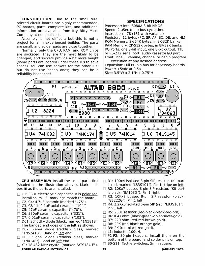
CONSTRUCTION: Due to the small size, printed circuit boards are highly recommended. PC boards, parts, complete kits, and additional information are available from Itty Bitty Micro Company at nominal cost.
Assembly is not difficult; but this is not a project for an inexperienced builder. The parts are small, and solder pads are close together.
Normally, only the CPU, RAM, and ROM chips are socketed. They are the most likely to be changed; and sockets provide a bit more height (some parts are located under these ICs to save space). You can use sockets for the other ICs, but do not use cheap ones; they can be a reliability headache!
CPU ASSEMBLY: Install the small parts first (shaded in the illustration above). Mark each box ▣ as the parts are installed.
□ C1: 33uF electrolytic capacitor. It is polarized; install so its +/‒ markings match the board.
□ C2, C4: 4.7uF ceramic (marked "475").□ C3, C8-11: 0.1uF axial ceramic ("104").□ C5: 47pF ceramic capacitor ("470").□ C6: 330pF ceramic capacitor ("331").□ C7: 0.01uF ceramic capacitor ("103").□ D01: Schottky diode (black, marked "1N5818")
The banded end goes on the left as shown.□ D02: Zener diode (reddish glass, marked
"1N5241B"). Band on left end.□ D03: Signal diode (reddish glass, marked
"1N4148"). Band on left end.□ Y1: 18.432 MHz crystal (marked "ATS184-E").
POPULAR RADIO-ELECTRONICS
□ R1: 100x4 isolated 8-pin SIP resistor. (Kit part is red, marked "L83S101"). Pin 1 stripe on left.
□ R2: 10Kx7 bussed 8-pin SIP resistor. (Kit part is black, "8A103G"). Pin 1 right.
□ R3: 10Kx8 bussed 9-pin SIP resistor. (black, "8B222G"). Pin 1 left.
□ R4: 2.2Kx3 isolated 6-pin SIP (red, "L83S101"). Pin 1 left.
□ R5: 200K resistor (red-black-black-org-brn).□ R6: 0.47 ohm (black-green-violet-silver-gold).□ R7: 220 ohm (red-red-brown-gold).□ R8: 20K (red-black-orange-gold).□ R9: 2K (red-black-red-gold).□ L1: Inductor 100uH.□ P1-P2: 30-pin headers. Install them on the
bottom of the board, and solder pins on top.□ S0-S11: Tactile switches, 5mm square.
35 JANUARY 1976
SPECIFICATIONSProcessor: Intel 8080A 8-bit NMOSSpeed: 2 uSec (min) bus cycle timeInstructions: 78 (181 with variants)Registers: 12 bytes (PC, SP, AF, BC, DE, and HL)ROM Memory: 2K-64K bytes, in 8K-32K banksRAM Memory: 2K-512K bytes, in 8K-32K banksI/O Ports: one 8-bit input, one 8-bit output, TTL or RS-232 serial port, audio cassette I/O portFront Panel: Examine, change, or begin program
execution at any desired addressExpansion: Full 60-pin bus for accessory boardsPower: +5vdc at 0.5aSize: 3.5"W x 2.1"H x 0.75"H

□ LEDs D0-11, A0-15: LEDs are polarized; the long wire is + (anode; right hole with arrow). Or, the short wire with the "cup" inside is ‒ (cathode; left hole on board). LED colors can be chosen for a pleasing display. For example, red and green LEDs can be used to indicate HEX or OCTAL address and data digits:
A15 ........ A8 A7 .......... A0 D7 .......... D0Hex RRRR GGGG RRRR GGGG RRRR GGGGOctal RR GGG RRR GG RRR GGG RR GGG RRR
LED brightness varies with color. Test your parts with the "diode" scale of your multimeter to find ones with similar brightness. SIP resistor R1 can also be changed to adjust brightness.
ICs and SOCKETS:
□ U1: Install a 40-pin IC socket with an open center for the parts under it. A machined-pin socket (Jameco 41136) or socket strips (Jameco 78642) are suggested.
U2-U7: Install the ICs directly, or in IC sockets. Pin 1 goes in the lower left! The text on all the ICs should be right-side-up.
□ U2: 8224 clock generator-driver.□ U3: 74HC174 hex latch.□ U4: 74HC02 quad 2-input NOR gate.□ U5: 74HC14 hex schmitt-trigger inverter.□ U6: 74LS145 decimal decoder/driver.□ U7: MC34063 switching regulator.
POPULAR RADIO-ELECTRONICS
TESTING: Don't insert your priceless 8080 yet! Let's see if everything works first. The Front Panel switches and LEDs are perfect for this. You'll need some clip leads and a multimeter. An oscilloscope is better, but not necessary.
Connect a regulated 5v power supply (+5v to P1 pin 10, GND to P1 pin 30). Current should not exceed 100mA. Check voltages on these IC pins:
U1 pin 20=+5v, pin 28=+12v, pin 11=─5vU2 pin 16=+5v, pin 9=+12vU3, U6 pin 16=+5vU4, U5 pin 14=+5vU7 pin 6=+5v, pin 5=+1.25v
The voltage on /RESET (P2 pin 21) should be high (+5v), and go low (GND) when you press and hold the RESET key for 2 seconds.
Ground OUT4 (P2 pin 5) to set the "6" output of decoder U6 low. Connect /RESET to OUT0 (P2 pin 1). The "RUN" LED should be on, and go out when you press the RESET key.
Test the other LEDs the same way. Connect /RESET to OUT0-OUT3, and GND to OUT4-OUT6 (U6 inputs) to select each of the 7 rows of 4 LEDs.
Test the other switches by selecting its row with OUT4-OUT6, and check the voltage on its IN0-IN3 line with your meter. IN0-IN3 will be high, and go low when you press the key.
Test for a 2 MHz signal at U2 pin 6 (Ø2TTL, 0-4v), pin 10 (Ø2, 0-12v), and pin 11 (Ø1, 0-12v).
If it all checks out, insert the 8080 into its socket. Continue to assemble the MIO board.
36 JANUARY 1976
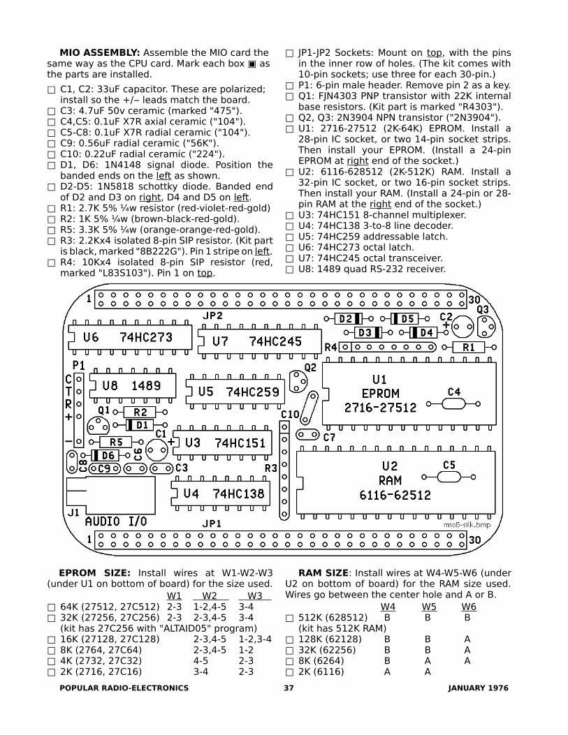
MIO ASSEMBLY: Assemble the MIO card the same way as the CPU card. Mark each box ▣ as the parts are installed.
□ C1, C2: 33uF capacitor. These are polarized;install so the +/‒ leads match the board.
□ C3: 4.7uF 50v ceramic (marked "475").□ C4,C5: 0.1uF X7R axial ceramic ("104").□ C5-C8: 0.1uF X7R radial ceramic ("104").□ C9: 0.56uF radial ceramic ("56K").□ C10: 0.22uF radial ceramic ("224").□ D1, D6: 1N4148 signal diode. Position the
banded ends on the left as shown.□ D2-D5: 1N5818 schottky diode. Banded end
of D2 and D3 on right, D4 and D5 on left.□ R1: 2.7K 5% ¼w resistor (red-violet-red-gold)□ R2: 1K 5% ¼w (brown-black-red-gold).□ R5: 3.3K 5% ¼w (orange-orange-red-gold).□ R3: 2.2Kx4 isolated 8-pin SIP resistor. (Kit part
is black, marked "8B222G"). Pin 1 stripe on left.□ R4: 10Kx4 isolated 8-pin SIP resistor (red,
marked "L83S103"). Pin 1 on top.
EPROM SIZE: Install wires at W1-W2-W3 (under U1 on bottom of board) for the size used.
W1 W2 W3 □ 64K (27512, 27C512) 2-3 1-2,4-5 3-4□ 32K (27256, 27C256) 2-3 2-3,4-5 3-4
(kit has 27C256 with "ALTAID05" program)□ 16K (27128, 27C128) 2-3,4-5 1-2,3-4□ 8K (2764, 27C64) 2-3,4-5 1-2□ 4K (2732, 27C32) 4-5 2-3□ 2K (2716, 27C16) 3-4 2-3
POPULAR RADIO-ELECTRONICS
□ JP1-JP2 Sockets: Mount on top, with the pins in the inner row of holes. (The kit comes with 10-pin sockets; use three for each 30-pin.)
□ P1: 6-pin male header. Remove pin 2 as a key.□ Q1: FJN4303 PNP transistor with 22K internal
base resistors. (Kit part is marked "R4303").□ Q2, Q3: 2N3904 NPN transistor ("2N3904").□ U1: 2716-27512 (2K-64K) EPROM. Install a
28-pin IC socket, or two 14-pin socket strips. Then install your EPROM. (Install a 24-pin EPROM at right end of the socket.)
□ U2: 6116-628512 (2K-512K) RAM. Install a 32-pin IC socket, or two 16-pin socket strips. Then install your RAM. (Install a 24-pin or 28-pin RAM at the right end of the socket.)
□ U3: 74HC151 8-channel multiplexer.□ U4: 74HC138 3-to-8 line decoder.□ U5: 74HC259 addressable latch.□ U6: 74HC273 octal latch.□ U7: 74HC245 octal transceiver.□ U8: 1489 quad RS-232 receiver.
RAM SIZE: Install wires at W4-W5-W6 (under U2 on bottom of board) for the RAM size used. Wires go between the center hole and A or B.
W4 W5 W6□ 512K (628512) B B B
(kit has 512K RAM)□ 128K (62128) B B A□ 32K (62256) B B A□ 8K (6264) B A A□ 2K (6116) A A
37 JANUARY 1976

SERIAL I/O: Install wires at W12-W13 (under U8 on bottom of board) to select TTL or RS-232. Etched jumpers are already in place for RS-232; cut them to use TTL levels for your serial I/O.
□ RS-232 □ TTL idle=‒5v to ‒15v idle=+3.3v to 5vactive=+5v to +15v active= 0 to +0.5v
R T R R T RW12 O O O O W12 O O O O
T TW13 R O O R W13 R O O R
O O O O


Digital Research CP/M 2.2
CP/M is in control when you see the A> prompt. "A" is the current disk drive. Type a Command, any optional filename(s) to use, and the RETURN or ENTER key. Use upper/lower case; CP/M converts to uppercase.
CP/M first checks for a builtin command (DIR, ERA, REN, SAVE, TYPE, or USER), then for a .COM file on the current disk (PIP, STAT etc.). If found, it runs it (you don't need to type the .COM part). If not found, it repeats the command with "?" after it. When the command finishes, it returns to the CP/M A> prompt, ready for the next command.
Each file has a unique FILENAME, with three parts:
d: disk drive (AP), followed by a colon (:)name 18 alphanumeric characters, including
! @ # $ % + ( ) but not < > . , : ; = ? * [ ].extent a period (.) and 03 more alphanumeric
characters for the file type. Examples:.ASM assembly language source file.BAS BASIC program file.COM executable program file.DAT data file.DOC formatted document file.HEX Intel HEX format file.SUB submit (batch) file.TXT simple text file
Filenames can be abbreviated, or use wild cards:
D: for any files on the D: disk driveFILE for FILE on the current disk driveD:FILE for FILE on the D: driveFILE.TXT for FILE.TXT on the current driveD:FILE.TXT for FILE.TXT on the D: driveFILE? any 5character name starting with FILEFILE.* any file named FILE. with any extentF*.TXT any .TXT file starting with F*.* matches everything
CONVENTIONS{...} Text in curly brackets are optional filenames.
(Don't type the curly brackets).[...] Text in square brackets are "switches" to enable
or disable various options. (Type the square brackets). Example: PIP uses [v] for for verify.
Quick Reference Card - 1
CONTROL CODES perform various "control" actions. "^" means hold down the CTRL key, then type the letter. Some control codes have their own key.
^C Warm boot; cancel command and restart CP/M^G Ring the console's bell^H (Backspace). Backup and delete last character^I (Tab). Move right to next tab stop^J (Line Feed). Move down a line^M (Return or Enter). Process current command, and
wait for the next command on a new line^P Toggle printer on/off (to duplicate console output).^Q Resume a long listing that was paused with ^S^S Stop (pause) a long listing^X Cancel; backup and delete all characters on line^Z Marks end of a file
BUILTIN commands are part of CP/M (called the CCP), and don't take any file space on disks. Filenames are optional, and can include wildcards.
B: change current disk to BDIR directory of all files on current disk DIR B: all files on B: disk DIR B:*.COM all .COM files on diskERA file(s) erase file (or files) on a disk ERA *.* erase all files on a disk (caution!)REN new=old rename old file to the new nameSAVE n file save "n" 256byte blocks of
memory starting at 0100h in fileTYPE file type (display on console) fileUSER n set user number (n=0 to 15)
TRANSIENT Commands are .COM program files on a disk. They can be anything; but CP/M comes with a simple but powerful set; able to write programs, or even build CP/M itself to run on other computers.
ASM Assemble 8080 source .ASM file into .HEX file. (Use DDT or LOAD to make it an executable .COM file.)
ASM FILE where FILE is named FILE.ASMASM FILE.SHL same, but use disks other than A:
S is source disk for FILE.ASMH is destination for hex FILE.HEX (or Z for none)L is destination for listing FILE.LST (or Z for none)
Digital Research CP/M 2.2
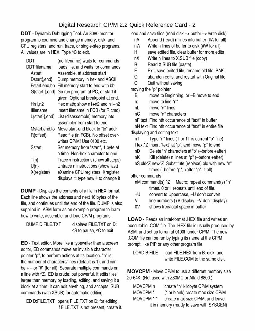
DDT Dynamic Debugging Tool. An 8080 monitor program to examine and change memory, disk, and CPU registers; and run, trace, or singlestep programs. All values are in HEX. Type ^C to exit.
DDT (no filename) waits for commandsDDT filename loads file, and waits for commands Astart Assemble, at address start Dstart{,end} Dump memory in hex and ASCII Fstart,end,bb Fill memory start to end with bb G{start}{,end} Go run program at PC, or start if
given. Optional breakpoint at end. Hn1,n2 Hex math; show n1+n2 and n1–n2 Ifilename Insert filename in FCB (for R cmd) L{start}{,end} List (disassemble) memory into
assembler from start to end Mstart,end,to Move startend block to "to" addr R{offset} Read file (in FCB). No offset over
writes CP/M! Use 0100 etc. Sstart Set memory from "start", 1 byte at
a time. Nonhex character to end. T{n} Trace n instructions (show all steps) U{n} Untrace n instructions (show last) X{register} eXamine CPU registers. Xregister
displays it; type new # to change it
DUMP Displays the contents of a file in HEX format.Each line shows the address and next 16 bytes of the file, and continues until the end of the file. DUMP is also supplied in .ASM form as an example program to learn how to write, assemble, and load CP/M programs.
DUMP D:FILE.TXT displays FILE.TXT on D:^S to pause, ^C to exit
ED Text editor. More like a typewriter than a screen editor, ED commands move an invisible characterpointer "p", to perform actions at its location. "n" isthe number of characters/lines (default is 1), and canbe + – or "#" (for all). Separate multiple commands on a line with ^Z. ED is crude; but powerful. It edits files larger than memory by loading, editing, and saving it a block at a time. It can edit anything, and accepts .SUB commands (with XSUB) for automatic editing.
ED D:FILE.TXT opens FILE.TXT on D: for editing.If FILE.TXT is not present, create it.
Quick Reference Card - 2
load and save files (read disk –> buffer –> write disk)nA Append (read) n lines into buffer (#A for all)nW Write n lines of buffer to disk (#W for all)H save edited file, clear buffer for more editsnX Write n lines to X.SUB file (copy)R Read X.SUB file (paste)E Exit; save edited file, rename old file .BAKO abandon edits, and restart with Original fileQ Quit without saving
moving the "p" pointerB move to Beginning, or –B move to endn: move to line "n"nL move "n" linesnC move "n" charactersnF text Find nth occurrence of "text" in buffernN text Find nth occurrence of "text" in entire file
displaying and editing textnT Type "n" lines (T or 1T is current "p" line)I text^Z Insert "text" at "p", and move "p" to endnD Delete "n" characters at "p" (–before +after)nK Kill (delete) n lines at "p" (–before +after)nS old^Z new^Z Substitute (replace) old with new "n"
times (–before "p", +after "p", # all)other commands
nM command(s) ^Z Macro; repeat command(s) "n" times. 0 or 1 repeats until end of file.
+U convert to Uppercase, –U don't convertV line numbers (+V display, –V don't display)0V shows free/total space in buffer
LOAD Reads an Intelformat .HEX file and writes an executable .COM file. The .HEX file is usually produced by ASM, and set up to run at 0100h under CP/M. The new .COM file can be run by typing its name at the CP/M prompt, like PIP or any other program file.
LOAD B:FILE load FILE.HEX from B: disk, andwrite FILE.COM to the same disk
MOVCPM Move CP/M to use a different memory size 2064K. (Not used with Z80MC or Altaid 8800.)
MOVCPM n create "n" kilobyte CP/M systemMOVCPM * (* or blank) create max size CP/MMOVCPM * * create max size CP/M, and leave
it in memory (ready to save with SYSGEN)
Digital Research CP/M 2.2
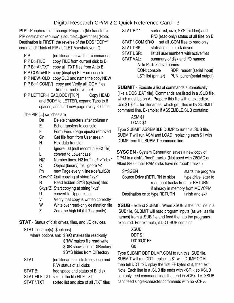
PIP Peripheral Interchange Program (file transfers). PIP destination=source1 {,source2...}[switches] (Note: Destination is FIRST; the reverse of the DOS "COPY" command! Think of PIP as "LET A:=whatever...").
PIP (no filenames) wait for commandsPIP B:=FILE copy FILE from current disk to B:PIP B:=A*.TXT copy all .TXT files from A: to B:PIP CON:=FILE copy (display) FILE on consolePIP NEW=OLD copy OLD and name the copy NEWPIP B:=*.COM[V] copy and Verify all .COM files
from current drive to B:PIP LETTER=HEAD,BODY[T8P] Copy HEAD
and BODY to LETTER, expand Tabs to 8 spaces, and start new page every 60 lines
The PIP [...] switches areDn Delete characters after column nE Echo transfers to consoleF Form Feed (page ejects) removedGn Get file from from User area nH Hex data transferI Ignore :00 (null record in HEX file)L convert to Lower caseN{2} Number lines. N2 for "line#:<Tab>"O Object (binary) file; ignore ^ZPn new Page every n lines(default60)Qxyz^Z Quit copying at string "xyz"R Read hidden .SYS (system) filesSxyz^Z Start copying at string "xyz"U convert to Upper caseV Verify that copy is written correctlyW Write over readonly destination fileZ Zero the high bit (bit 7 or parity)
STAT Status of disk drives, files, and I/O devices.
STAT filename(s) {$options}where options are: $R/O makes file readonly
$R/W makes file readwrite$DIR shows file in DIRectory$SYS hides from DIRectory
STAT (no filenames) lists free space andR/W status of all disks
STAT B: free space and status of B: diskSTAT FILE.TXT size of the file FILE.TXTSTAT *.TXT sorted list and size of all .TXT files
Quick Reference Card - 3
STAT B:*.* sorted list, size, SYS (hidden) and R/O (readonly) status of all files on B:
STAT *.COM $R/O set all .COM files to readonlySTAT DSK: statistics of all disk drivesSTAT USR: list all user numbers with active filesSTAT VAL: summary of disk and I/O names:
A: to P: disk drive namesCON: console RDR: reader (serial input)LST: list (printer) PUN: punch(serial output)
SUBMIT Execute a list of commands automatically (like a DOS .BAT file). Commands are listed in a .SUB file, which must be on A:. Prepare this file with a text editor. Use $1 $2 ... for filenames, which get filled in by SUBMIT command line. Example: If ASSEMBLE.SUB contains:
ASM $1LOAD $1
Type SUBMIT ASSEMBLE DUMP to run this .SUB file. SUBMIT will run ASM and LOAD, replacing each $1 with DUMP from the SUBMIT command line.
SYSGEN System Generation saves a new copy of CP/M in a disk's "boot" tracks. (Not used with Z80MC or Altaid 8800; their RAM disks have no "boot" tracks.)
SYSGEN starts the programSource Drive (RETURN to skip) type drive letter to
read boot tracks from, or RETURNif already in memory from MOVCPM
Destination on x: type RETURN finish and exit
XSUB extend SUBMIT. When XSUB is the first line in a .SUB file, SUBMIT will read program inputs (as well as file names) from a .SUB file and feed them to the programs executed. For example, if DDT.SUB contains:
XSUBDDT $1D0100,01FFG0
Type SUBMIT DDT DUMP.COM to run this .SUB file. SUBMIT will run DDT, replacing $1 with DUMP.COM, then tell DDT to Display the first FF bytes of it, then exit.Note: Each line in a .SUB file ends with <CR>, so XSUB can only feed command lines that end in <CR>. I.e. XSUB can't feed singlecharacter commands with no <CR>.