polymer spreading on substrates with nanoscale grooves using molecular...
TRANSCRIPT

Polymer spreading on substrates withnanoscale grooves using moleculardynamics
Brooklyn A Noble and Bart Raeymaekers
Department of Mechanical Engineering, University of Utah, Salt Lake City, UT 84112, United States ofAmerica
E-mail: [email protected]
Received 22 September 2018, revised 17 November 2018Accepted for publication 11 December 2018Published 4 January 2019
AbstractUnderstanding how liquid polymer interacts with and spreads on surfaces with nanoscale texturefeatures is crucial for designing complex nanoscale systems. We use molecular dynamics tosimulate different types of polymer as they spread on substrates with a single nanoscale groove.We study how groove design affects the potential energy of a substrate and how this governspolymer spreading and orientation. Based on our simulations, we show that groove shape, polymerchemistry, and polymer molecule entanglement are the three parameters that determine polymerspreading on a nanoscale groove. We provide a molecular-level explanation of the underlyingphysical mechanisms, and we illustrate this fundamental understanding by designing a network ofgrooves to engineer user-specified polymer spreading and coverage. This work has implicationsfor nanoscale systems and devices that involve the design of complex groove networks with anultrathin polymer coating, including micro and nanoelectromechanical devices, nanoimprintlithography, flexible electronics, antibiofouling coatings, and hard disk drives.
Supplementary material for this article is available online
Keywords: polymer spreading, nanoscale groove, perfluoropolyether, molecular dynamicssimulation
(Some figures may appear in colour only in the online journal)
1. Introduction
Ultrathin liquid polymer films are crucial to the functionalityof numerous applications and serve as protective lubricantcoatings on hard disk drives [1], antibiofouling coatings formedical devices [2, 3], and are an integral part of manynanoscale manufacturing processes [4], among many others.However, controlling spreading and coverage of an ultrathinliquid polymer film is challenging because surface forces, asopposed to body forces like gravity, dominate on the nanos-cale. Several research groups, including ours, have studiedpolymer spreading on a flat substrate [5–9], whereas only afew research groups have studied polymer spreading ona surface with nanoscale topographical features, despiteevidence that such features significantly affect polymerspreading.
Researchers have documented, both experimentally andnumerically, and for a variety of solid/liquid systems, thatsubstrates with a pattern of unidirectional grooves can causeanisotropic spreading [10–13], anisotropic wetting [11, 13],and enhanced polymer retention or reflow [14, 15]. Exper-imental works have documented such observations on sur-faces with unidirectional grooves of various shape and size.Zhang et al [10] showed that perfluoropolyether (PFPE)polymer spread predominantly along 30 or 50 nm deepunidirectional rectangular grooves on polycarbonate sub-strates and that spreading decreased with increasing polymermolecular weight. Khare et al [11] observed anisotropicwetting and fluidic transport of glycerin droplets on softpolydimethylsiloxane substrates with 500 nm deep uni-directional sinusoidal grooves. They observed that thecontact line between the liquid and solid advanced in a
Nanotechnology
Nanotechnology 30 (2019) 095701 (8pp) https://doi.org/10.1088/1361-6528/aaf7cc
0957-4484/19/095701+08$33.00 © 2019 IOP Publishing Ltd Printed in the UK1

pinning-depinning-repinning manner and suggested that theliquid experienced the presence of energy barriers imposedby the nanoscale features. Fukuzawa et al [16] explored thisconcept further by patterning a silicon substrate with 2.5 nmoxide ridges, which locally altered the wettability of 10 nmPFPE films. They found that in addition to the surfaceenergy of the liquid/air and liquid/solid interfaces, wett-ability was determined by the intermolecular interactionbetween the liquid and solid, which even dominated capil-lary pressure.
Numerical studies have supplemented experiments,which become increasingly difficult with decreasing scale.Zhang et al [12] used Monte Carlo simulations to show thatthe polymer spreading rate increases when approaching theedges of rectangular grooves, and they intuitively attributedthis to the increased surface force inside a groove, which issurrounded by as many as three surfaces. Hirvi et al [13]employed molecular dynamics (MD) to simulate the wettingof water droplets on polyvinyl chloride surfaces with0.369–3.070 nm deep rectangular grooves and observed ani-sotropic spreading with a corrugated contact line where watermolecules spread further along the grooves than perpend-icular to the grooves. They explained that the nanoscalefeatures confine the droplet radius in the direction perpend-icular to the grooves, acting as an energy barrier.
Comparing published works that study liquid spreadingon substrates with unidirectional nanoscale grooves, we findthat similar observations are documented for different sub-strates, groove shapes, and liquids, using both simulations andexperiments. However, some researchers explain that liquidspreading is accelerated along a groove [10, 12], whereasothers describe an energy barrier that seemingly confinesspreading perpendicular to the groove direction [11, 13, 16].
Although crucial to the design of ultrathin liquid polymerfilms for use in engineering applications, no comprehensiveunderstanding of the physical mechanisms that govern liquidpolymer spreading in the presence of nanoscale texture fea-tures, particularly grooves, seems to exist. This paper pro-vides a molecular-level explanation of liquid polymerspreading on a substrate with a nanoscale groove. We use MDsimulations to: (1) quantify how nanoscale groove shapeaffects polymer spreading, (2) describe the physicalmechanisms underlying ultrathin polymer film spreading in ananoscale groove, and (3) design a network of nanoscalegrooves to control spreading for user-specified polymercoverage. We specifically focus on substrates with a singlenanoscale groove. We show that anisotropic polymerspreading on a substrate with nanoscale grooves is not duesolely to energy barriers that confine the contact line in thedirection perpendicular to grooves, as others have previouslysuggested. Instead, we show that anisotropic spreading canexist within a single groove, and we demonstrate that grooveshape determines the degree of anisotropic spreading.Although it has been previously postulated, we quantify howthe edge of a groove causes anisotropic spreading and poly-mer alignment such that we can predict and control spreading.
2. Methods
We perform MD simulations of liquid polymer spreading on aflat substrate and substrates with a triangle, square, or wave-shaped groove using a coarse-grained bead-spring (CGBS)model and the large-scale atomic/molecular massively par-allel simulator [17, 18]. The CGBS model averages atomicinteractions for computational simplicity yet preserves theessence of the molecular structure. We consider two types ofPFPE polymer commonly used in micro- and nanoscaledevices, both of which have a backbone structure ofX–[(O–CF2–CF2)p–(O–CF2)q]–O–X (p/q≅2/3): a Zdolmolecule, which terminates with a functional hydroxyl group(X=CF2–CH2–OH), and a Z molecule, which terminateswith a nonfunctional trifluoromethyl group (X=CF3). Wevary the polymer molecule length 10�N�400 beadsfor both polymer types while maintaining a constant beadmass of 0.2 kg mol−1, thus varying the molecular weight2�M�80 kg mol−1. The substrate consists of three rigidlayers of nonfunctional beads and a fraction of functionalbeads 0%�Sf �100% on the top layer only, which stronglyattract the functional polymer end beads of Zdol. Thepotential function interactions are similar to validated poten-tials used in previous research [7–9, 19–21] and are discussedin detail in the supplementary information, which is availableonline at stacks.iop.org/NANO/30/095701/mmedia.
We use a quasi-random distribution [22] to define theinitial position of the first bead of every polymer moleculeand use a random walk approach to define the initial positionof the additional beads belonging to each molecule, startingfrom the first bead. The polymer is free to move according tothe microcanonical ensemble, and we hold the temperatureconstant at 300 K using a Langevin thermostat. The polymerequilibrates within a 23 nm diameter cylinder for at least 7 ns,which represents the pipet used in experiments to deposit apolymer droplet on a substrate. During equilibration, thepotential energy of the system initially increases beforeapproaching a constant value. We then remove the cylinderand the polymer spreads on the substrate for approximately200 ns. We use a timestep of 0.03 ps throughout all MDsimulations. The substrate is rigid, and we impose periodicboundary conditions around the simulation box, although thepolymer does not cross any boundary during any simulationin this work.
3. Results and discussion
3.1. Groove shape
Figure 1 illustrates spreading of short (N=10, M=2 kg mol–1), functional polymer (Zdol) on nonfunctionalsubstrates (Sf=0%) with different groove shapes. (a) a flatsubstrate, (b) a triangular groove with θ=60°, (c) a wavegroove (one period of a cosine wave), and (d) a squaregroove. All MD simulation parameters remain constantexcept the groove shape. For each groove shape, we show thespreading distance parallel to the groove d|| (blue square
2
Nanotechnology 30 (2019) 095701 B A Noble and B Raeymaekers

markers) and perpendicular to the groove d⊥ (black trianglemarkers) as a function of spreading time, where 7×10⁶
timesteps dτ corresponds to approximately 200 ns ofspreading. Note that the spreading distance perpendicular tothe groove is the maximum distance the polymer spreadsalong the length of the substrate in the x–y plane, which isdifferent from the apparent spreading distance obtained froma projection onto the x–z plane. We quantify spreading par-allel to the groove as the polymer spreading distance in the z-direction, i.e. along the groove. We simultaneously evaluatethe polymer thickness to determine whether a central dropletexists, which we define as a polymer thickness greater thanthe 3σ precursor film, where σ is the diameter of one bead.Solid markers indicate that a central droplet exists and hollow
markers indicate that the central droplet has depleted. Foreach groove shape, we show inset images that illustrate thesimulation in the x–y plane (side view) just before spreadingand in the x–z plane (top view) after 200 ns of spreading,including a magnified view of polymer molecules. The sub-strate is invisible in the top view for clarity.
From figure 1 we observe that each droplet spreads to athin film and that d⊥;400σ after 200 ns (black trianglemarkers), independent of the groove shape. Because d⊥ isapproximately the same for the flat substrate and substrateswith a nanoscale groove, we show that a single groove doesnot inhibit spreading perpendicular to the groove direction.For the flat, wave, and square grooves, d|| is similar to d⊥ andalso approaches 400σ after 200 ns, i.e. d||/d⊥;1, indicating
Figure 1. Spreading parallel to the groove d|| (blue square markers) and spreading perpendicular to the groove d⊥ (black triangle markers) asa function of spreading time for short, functional polymer on nonfunctional substrates with different shapes: (a) flat substrate, (b) triangulargroove (c) wave groove, and (d) square groove. Insets show the simulation in the x–y plane (side view) just before spreading and in the x–zplane (top view) after 200 ns, including a magnified view of polymer molecules.
3
Nanotechnology 30 (2019) 095701 B A Noble and B Raeymaekers
isotropic spreading. However, for the triangular groove,polymer spreads more than double in the direction parallel asopposed to perpendicular to the groove, i.e. d||/d⊥>2. Thus,anisotropic spreading may occur with only a single groovebecause spreading is accelerated parallel to the groovedirection, even though spreading is not inhibited perpend-icular to the groove direction. The magnified insets of poly-mer in the x–z plane after 200 ns show that spreading occursprimarily where the groove forms a sharp edge, e.g. the 90°and 60° edges of the square and triangular grooves, respec-tively. We also observe that the polymer molecules align withthe groove at these edges, whereas for the flat substrate andwave groove, polymer molecules do not orient in any part-icular direction. Thus, the polymer molecules at the edges ofthe triangular and square grooves are smectic in phase, as thepolymer molecules orient parallel and in a well-defined plane.This observation agrees with that of Zhang et al [10, 12] whoshowed that polymer spreading is affected by the edge ofgroove features. We explain these observations and the ani-sotropic polymer spreading in the triangular groove based onthe potential energy associated with each groove shape.
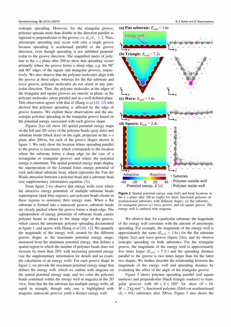
Figures 2(a)–(d) show 2D spatial potential energy mapson the left and 2D views of the polymer beads (gray dots) andsubstrate beads (black dots) on the right, projected on the x–yplane after 200 ns, for each of the groove shapes shown infigure 1. We only show the location where spreading parallelto the groove is maximum, which corresponds to the locationwhere the substrate forms a sharp edge (in the case of arectangular or triangular groove) and where the potentialenergy is minimum. The spatial potential energy maps displaythe superposition of the Lennard Jones energy potential ofeach individual substrate bead, which represents the Van derWaals attraction between a polymer bead and a substrate bead(see supplementary information equation (3)).
From figure 2 we observe that energy wells exist wherethe attractive energy potentials of multiple substrate beadssuperimpose (dark blue regions), and polymer beads cluster inthese regions to minimize their energy state. When a flatsubstrate is formed into a nanoscale groove, substrate beadsare closely packed where the groove forms a sharp edge. Thesuperposition of energy potentials of substrate beads causespolymer beads to attract to the sharp edge of the groove,which causes the anisotropic polymer spreading documentedin figure 1, and agrees with Zhang et al [10, 12]. We quantifythe magnitude of the energy well created by the differentgroove shapes as the maximum potential energy range,measured from the minimum potential energy, that defines aspatial region in which the number of polymer beads does notincrease by more than 20% with increasing potential energy(see the supplementary information for details and an exam-ple calculation of an energy well). For each groove shape infigure 2, we provide the maximum potential energy range thatdefines the energy well, which we outline with magenta onthe spatial potential energy map, and we color the polymerbeads contained within the energy well in magenta in the 2Dview. Note that the flat substrate has multiple energy wells, allequal in strength, though only one is highlighted withmagenta; nanoscale grooves yield a distinct energy well.
We observe that, for a particular substrate, the magnitudeof the energy well correlates with the amount of anisotropicspreading. For example, the magnitude of the energy well isapproximately the same (Ewell =1.6ε) for the flat substrate(figure 2(a)) and wave groove (figure 2(b)), and we observeisotropic spreading on both substrates. For the triangulargroove, the magnitude of the energy well is approximatelyfive times larger (Ewell =7.2ε) and the spreading distanceparallel to the groove is two times larger than for the lattertwo shapes. We further describe the relationship between themagnitude of the energy well and spreading distance byevaluating the effect of the angle of the triangular groove.
Figure 3 shows polymer spreading parallel (red squaremarkers) and perpendicular (black triangle markers) to trian-gular grooves with 60�θ�180° for short (N=10,M=2 kg mol–1), functional polymer (Zdol) on nonfunctional(Sf =0%) substrates after 200 ns. Figure 3 also shows the
Figure 2. Spatial potential energy map (left) and bead locations inthe x–y plane after 200 ns (right) for short, functional polymer onnonfunctional substrates with different shapes: (a) flat substrate,(b) triangular groove (c) wave groove, and (d) square groove. Theenergy well is outlined with magenta.
4
Nanotechnology 30 (2019) 095701 B A Noble and B Raeymaekers

magnitude of the energy well (blue circle markers). All MDsimulation parameters remain constant except the substrateangle. Each simulation was repeated three times, and wereport the average. A triangular groove of 60° is the smallestangle we consider because a smaller angle results in over-lapping substrate beads at the edge of the groove. Insets showspatial potential energy maps for select triangular grooveangles with the energy wells outlined in magenta.
From figure 3 we observe that d⊥ is independent ofthe triangular groove angle. In contrast, d|| is a nonlinearfunction of the triangular groove angle such that a global andlocal maximum exist at 60° and 120°, respectively. For90�θ�100° and 140�θ�180°, we observe that the d||and d⊥ are similar and, thus, result in nearly isotropicspreading. The magnitude of the energy well Ewell also variesnonlinearly with θ and shows a similar trend as the relation-ship between d|| and θ. The correlation coefficient between d||and Ewell is 0.93, indicating that polymer spreading parallel tothe groove is dependent on the angle of the triangular groove.Thus, for short Zdol polymer on nonfunctional substrates, themagnitude of the energy well controls the strength with whichpolymer beads attract to the groove, promoting polymerspreading in the groove but not affecting spreadingperpendicular to the groove.
Thus, we demonstrate that groove shape significantlyaffects the degree of anisotropic spreading. Potential energymaps reveal the underlying mechanism as potential energywells that promote spreading along a groove. Furthermore,these potential energy wells vary with groove shape such thata specific spreading behavior can be engineered. Many moregroove designs exist that are not included in this study.However, with a specific application in mind, a potential
energy map allows evaluating the strength of the potentialenergy well for any specific groove design.
3.2. Modes of polymer spreading
We compare the physical mechanisms that drive ultrathinpolymer film spreading in a nanoscale groove to those thatexist on a flat substrate, which we documented in previouswork [7]. Figure 4 shows the polymer spreading distanceparallel versus perpendicular to the groove after 200 ns fortwelve simulations that represent the extremes of parameterswe evaluate. Triangle markers indicate functional polymer(Zdol) on a functional substrate (Sf =100%), circle markersindicate functional polymer on a nonfunctional substrate(Sf =0%), and square markers indicate nonfunctional poly-mer (Z). Blue and red markers indicate a triangular groovewith θ=60° and a flat substrate, respectively. We selectthese substrates because a triangular groove with θ=60°yields the most anisotropic spreading for short, functionalpolymer on a nonfunctional substrate, whereas the flat sub-strate yields isotropic spreading. Hollow and solid markersindicate short (N=10, M=2 kg mol–1) and long (N=400,M=80 kgmol−1) polymer molecules, respectively. We repeateach simulation twice and report the average, where errorbars show the minimum and maximum. Two lines are plottedfor reference: the 1–1 line indicates isotropic polymerspreading and the 2–1 dashed line indicates twice as muchspreading in the direction parallel compared to perpendicularto the groove.
From figure 4 we observe that isotropic polymerspreading occurs on the flat substrate, as expected (red mar-kers are located near the 1–1 line). We also observe that short,
Figure 3. Polymer spreading distance parallel to the groove (redsquare markers) and perpendicular to the groove (black trianglemarkers) after 200 ns and the magnitude of the energy well of eachsubstrate (blue circle markers) as a function of triangular grooveangle for short, functional polymer molecules on nonfunctionalsubstrates. Insets show spatial potential energy maps for selectgroove angles with the energy wells outlined in magenta.
Figure 4. Polymer spreading distance parallel versus perpendicularto the groove after 200 ns for twelve simulations that represent theextremes of parameters studied. The 1–1 line indicates equalspreading in each direction and the 2–1 dashed line indicatesspreading twice as far in the direction parallel to the groovecompared to the direction perpendicular to the groove. Three distinctspreading regimes are identified.
5
Nanotechnology 30 (2019) 095701 B A Noble and B Raeymaekers
functional polymer on a functional substrate spreadsapproximately 100σ in each direction, whereas short, non-functional polymer spreads approximately 400σ in eachdirection. This is in agreement with our previous work on thespreading kinetics of liquid polymer on flat substrates wherewe identified three spreading regimes based on competingphysical mechanisms [7].
Similar to polymer spreading on a flat substrate, we findthat polymer spreading in a nanoscale groove can be cate-gorized into three regimes, marked with colored regions infigure 4. The green region represents pressure driven, che-mically inhibited flow and applies to short, functional poly-mer on a functional substrate. In this regime, spreading isinhibited by the chemical attraction of functional polymer endbeads to the functional substrate. Regardless of the presenceof a groove, we observe nearly isotropic spreading in thisregime.
The cyan region represents pressure driven, entanglementinhibited flow and applies to long, functional and nonfunc-tional polymer molecules. All solid markers fall within thisregion. In this regime, spreading is inhibited by entanglementof long polymer molecules. Each of these simulations yieldsan entanglement index EI>5, where the entanglement indexis defined as the average number of polymer beads thatremain within 2σ of each other for at least 100 000 timesteps[7, 23]. Note that EI≈4 indicates molecules are largelyuntangled because the presence of persistent contacts fromadjacent polymer beads of the same molecule cause anEI>0. Polymer spreading is still affected by the triangulargroove with θ=60°, resulting in some anisotropic spreading1<d||/d⊥<2. This result is in agreement with experimentsof Zhang et al [10] that show anisotropic spreading decreaseswith increasing molecular weight.
The yellow region represents pressure driven flow withno inhibiting mechanism and applies to short, functional ornonfunctional polymer on a nonfunctional substrate. Thepolymer molecules do not remain entangled because amolecule length of N=10 is below the critical entanglementlength, initially established for a primitive chain by Kremeret al [24] and previously identified for our model as N≈20[7–9]. In this regime, spreading is most affected by the tri-angular groove with θ=60°, resulting in d||/d⊥>2 suchthat polymer spreads more than twice as much parallel thanperpendicular to the groove.
We have previously demonstrated that polymer spread-ing on a flat substrate does not follow a simple diffusion law,but instead one or more spreading regimes may exist that areattributed to competing physical mechanisms: a pressuredifference in the polymer droplet, entanglement of polymermolecules, and attraction of functional chemical groups [7].The presence of these physical mechanisms depends onpolymer type, polymer length, and substrate composition. Wefind that polymer spreading in a groove and on a flat substrateare governed by the same physical mechanisms. Thus, evenfor groove geometries that yield a strong energy well, ani-sotropic spreading does not always occur because spreading isaffected by other parameters such as polymer length, polymertype, and functional substrate fraction such that, for some
cases, the intermolecular interactions within the polymerdominate the interactions between the polymer and the sub-strate. As such, we observe less spreading for long polymermolecules on all substrates due to entanglement, and weobserve significantly less spreading for short functionalpolymer on functional substrates due to the attraction ofchemical groups. For long polymer molecules, we alsoobserve the most variability in spreading distance becauseentanglement dominates spreading, and a random componentis inherently associated with this regime.
3.3. Groove network design
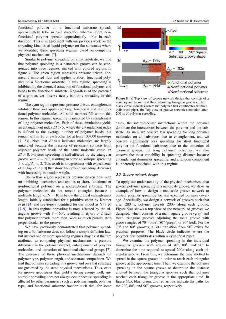
To apply our understanding of the physical mechanisms thatgovern polymer spreading in a nanoscale groove, we show anexample of how to design a nanoscale groove network tocontrol polymer spreading for user-specified polymer cover-age. Specifically, we design a network of grooves such thatafter 200 ns, polymer spreads 200σ along each groove.Figure 5(a) shows a top view of the network of grooves wedesigned, which consists of a main square groove (gray) andthree triangular grooves adjoining the main groove withgroove angles of 70° (blue), 80° (green), or 90° (red). For the70° and 80° grooves, a 30σ transition from 90° exists forpractical purposes. The black circle indicates where thepolymer first equilibrates within a cylindrical pipet.
We examine the polymer spreading in the individualtriangular grooves with angles of 70°, 80°, and 90° todetermine the time required to spread 200σ along each tri-angular groove. From this, we determine the time allotted tospread in the square groove in order to reach each triangulargroove at the appropriate time. Then, we examine the polymerspreading in the square groove to determine the distanceallotted between the triangular grooves such that polymerreached each triangular groove at the appropriate time. Infigure 5(a), blue, green, and red arrows indicate the paths forthe 70°, 80°, and 90° grooves, respectively.
Figure 5. (a) Top view of groove network design that consists of amain square groove and three adjoining triangular grooves. Theblack circle indicates where the polymer first equilibrates within acylindrical pipet. (b) Top view of groove network simulation after200 ns of polymer spreading.
6
Nanotechnology 30 (2019) 095701 B A Noble and B Raeymaekers

Figure 5(b) shows a top view of the simulation shown infigure 5(a) after 200 ns of spreading. The spreading distanceof the polymer along each groove is d90° =199σ, d80° =182σ, and d70° =195σ, thus achieving the objective ofspreading approximately 200σ along each groove. Repeatingthis simulation three times, we quantify the error of thepolymer spreading distance along each groove as 6%–10%.By understanding how polymer spreads in a single groove,we can design a network of grooves to engineer and controlpolymer spreading and coverage on a substrate by changingonly the substrate groove design. As such, nanoscale groovesenable engineering spreading such that the following can beobtained: anisotropic polymer spreading using only a nanos-cale groove, increased spreading along a groove for applica-tions where polymer film depletion is a problem, or a user-specified polymer spreading or coverage pattern using groovenetworks. This research is relevant to many engineeringapplications and research fields where control of ultrathinliquid polymer films on solid surfaces is desirable, includingtribology, manufacturing, and interface science, amongothers.
4. Conclusions
We show that anisotropic polymer spreading on a substratewith nanoscale grooves is not due solely to energy barriersthat confine the contact line in the direction perpendicular togrooves, as others have previously suggested. Instead, when agroove exhibits a sharp edge, the intermolecular forcesbetween the polymer and substrate dominate to yield aniso-tropic spreading that is preferential in the direction parallel tothe groove. Three factors determine if anisotropic polymerspreading occurs: (1) substrate geometry (groove shape), (2)chemical end groups of the polymer (Z or Zdol), and (3)polymer molecule length. The groove design affects spread-ing because the energy potentials of closely packed substratebeads at the edge of the groove superimpose to stronglyattract polymer beads. The energy well at the edge of thegroove promotes polymer to spread parallel to the groovewithout affecting spreading perpendicular to the groovebecause polymer molecules cluster where the energy isstrongly attractive to minimize their energy state. Quantifyingthe magnitude of energy wells enables predicting polymerspreading. Triangular substrates with angles 60�θ�80°and 110�θ�130° yield a strong energy well, which leadsto anisotropic spreading unless inhibited by the attraction ofchemical groups to the substrate or the entanglement of longpolymer molecules.
Acknowledgments
This work used the Extreme Science and Engineering Dis-covery Environment (XSEDE) Comet at the San DiegoSupercomputer Center through allocation MSS150011, whichis supported by the National Science Foundation grant num-ber ACI-1053575. The support and resources from the Center
for High Performance Computing at the University of Utahare gratefully acknowledged. Brooklyn Noble also gratefullyacknowledges the Department of Energy Stewardship ScienceGraduate Fellowship program support, provided under grantnumber DE-NA0003864.
ORCID iDs
Bart Raeymaekers https://orcid.org/0000-0001-5902-3782
References
[1] Marchon B 2009 Lubricant design attributes for subnanometerhead-disk clearance IEEE Trans. Magn. 45 872–6
[2] Maitz M F 2015 Applications of synthetic polymers in clinicalmedicine Biosurface Biotribology 1 161–76
[3] Epstein A K, Wong T-S, Belisle R A, Boggs E M andAizenberg J 2012 Liquid-infused structured surfaces withexceptional anti-biofouling performance Proc. Natl Acad.Sci. 109 13182–7
[4] Srinivasan A and Bandyopadhyay S 2016 Advances inPolymer Materials and Technology (Boca Raton, FL: CRCPress)
[5] Karis T E, Kim W T and Jhon M S 2005 Spreading anddewetting in nanoscale lubrication Tribol. Lett. 18 27–41
[6] Popescu M N, Oshanin G, Dietrich S and Cazabat A M 2012Precursor films in wetting phenomena J. Phys.: Condens.Matter 24 243102
[7] Noble B A, Mate C M and Raeymaekers B 2017 Spreadingkinetics of ultrathin liquid films using molecular dynamicsLangmuir 33 3476–83
[8] Noble B A, Ovcharenko A and Raeymaekers B 2016 Terracedspreading of nanometer-thin lubricant using moleculardynamics Polymer 84 286–92
[9] Noble B, Ovcharenko A and Raeymaekers B 2014 Quantifyinglubricant droplet spreading on a flat substrate usingmolecular dynamics Appl. Phys. Lett. 105 151601
[10] Zhang H, Mitsuya Y and Yamada M 2003 Spreadingcharacteristics of molecularly thin lubricant on surfaces withgroove-shaped textures: effects of molecular weight andend-group functionality J. Tribol. 125 350
[11] Khare K, Zhou J and Yang S 2009 Tunable open-channelmicrofluidics on soft poly(dimethylsiloxane) (PDMS)substrates with sinusoidal grooves Langmuir 25 12794–9
[12] Zhang H, Mitsuya Y and Yamada M 2002 Spreadingcharacteristics of molecularly thin lubricant on surfaces withgroove-shaped textures: Monte Carlo simulation andmeasurement using PFPE film J. Tribol. 124 575
[13] Hirvi J T and Pakkanen T A 2007 Wetting of nanogroovedpolymer surfaces Langmuir 23 7724–9
[14] Kim P, Kreder M J, Alvarenga J and Aizenberg J 2013Hierarchical or not?Effect of the length scale and hierarchyof the surface roughness on omniphobicity of lubricant-infused substrates Nano Lett. 13 1793–9
[15] Tan A H and Cheng S W 2006 A novel textured design forhard disk tribology improvement Tribol. Int. 39 506–11
[16] Fukuzawa K, Deguchi T, Yamawaki Y, Itoh S,Muramatsu T and Zhang H 2008 Control of wettability ofmolecularly thin liquid films by nanostructures Langmuir 242921–8
[17] Plimpton S 1995 Fast parallel algorithms for short-rangemolecular dynamics J. Comput. Phys. 117 1–19
[18] Towns J et al 2014 XSEDE: accelerating scientific discoveryComput. Sci. Eng. 16 62–74
7
Nanotechnology 30 (2019) 095701 B A Noble and B Raeymaekers
[19] Guo Q, Izumisawa S, Phillips D M and Jhon M S 2003 Surfacemorphology and molecular conformation for ultrathin lubricantfilms with functional end groups J. Appl. Phys. 93 8707–9
[20] Hsia Y T, Guo Q, Izumisawa S and Jhon M S 2005 Thedynamic behavior of ultrathin lubricant films Microsyst.Technol. 11 881–6
[21] Chen H, Guo Q and Jhon M S 2007 Effects of molecularstructure on the conformation and dynamics ofperfluoropolyether nanofilms IEEE Trans. Magn. 43 2247–9
[22] Kocis L and Whiten W J 1997 Computational investigations oflow- discrepancy sequences ACM Trans. Math. Softw. 23266–94
[23] Likhtman A E and Ponmurugan M 2014 Microscopicdefinition of polymer entanglements Macromolecules 471470–81
[24] Kremer K and Grest G S 1990 Dynamics of entangled linearpolymer melts: a molecular-dynamics simulation J. Chem.Phys. 92 5057–86
8
Nanotechnology 30 (2019) 095701 B A Noble and B Raeymaekers