polymel polyester monobloc enclosures - rapid … · polymel polyester monobloc enclosures 5...
TRANSCRIPT

1 2 3 4 65
1112 10 9 8 7
3/38
POLYMEL polyester monobloc enclosures
5 Enclosure with a tempered glass transparent door, maintaining the IP66 and IK08 (5J) degrees of protection.
1 The built-in canopy protects the door and the sealing gasket.
9 Depth adjustable mounting plate supports with positions every 12.5 mm.
03_038_039.indd 3803_038_039.indd 38 21/2/08 10:23:1021/2/08 10:23:10

3/39
2 Wall fixing from the outside with stainless steel or polyester wall brackets.
3 The fixing strips, notched every 25 mm, located at the back of the enclosure allow direct attachment of mounting rails or other devices, thus reducing assembly time.
6 The lock system is located outside the sealed area to maintain the IP66 degree of protection.
4 Four moulded bosses on the inside of the door help to assemble accessories. For maximum usable space, the door has a grid pattern for centring components. Door opening more than 180°.
12 Self-ventilation windows at the rear of the enclosure.
10 Direct wall fixing with a plug to maintain the double insulation and watertightness.4 inserts at the back for fixing the mounting plate.
11 Reversible polyester internal door with grid pattern for industrial control.
7 Interior hinges fixed into the door. The built-inpolyurethane sealing gasket guarantees IP66.
8 Ventilation louvers provide natural ventilation of the interior of enclosure, thus preventing condensation.
03_038_039.indd 3903_038_039.indd 39 21/2/08 10:23:1221/2/08 10:23:12

3/40
POLYMEL Polyester enclosuresIP66 (EN 60529)
PLM-75 PLM-75/CME
Hot-press moulded fibreglass-reinforced polyester enclosure, in grey RAL-7032.
Construction specifications
c Body of one single piece: monobloc.
c Fully reversible.
c Intended for use in both indoor and outdoor environments.
c A wide range of accessories enabling use in distribution, control and
measurement panels for industrial and infrastructure facilities.
c Standard double bar lock or three-point lock with handle (without insert).
Technical specifications
c Conforms to general rules for empty enclosures established in IEC and EN 62208.
c IP66 conforming to IEC 60529 (EN 60529).
c High resistance to mechanical impacts IK10 (20 J) conforming to IEC and EN 62262.
c Self-extinguishing, conforming to IEC 60695-2-1 (960°).
c Extreme operating temperatures from –50 to +150 ºC.
c Suitable for double insulation profiles conforming to IEC 60439-1 (EN 60439-1).
c Resistant to corrosion.
03_040_050_EN.indd 4003_040_050_EN.indd 40 2/4/08 12:50:102/4/08 12:50:10

3/41
POLYMEL Polyester enclosuresIP66 (EN 60529)
* PLM-32 model in polycarbonate.
(1) Four-point locking system.
TABLE OF MODELS, DIMENSIONS AND REFERENCES
External dimensions (mm)
Plain Transparent door door
Plain door Mounting plates
Adjustable plate
support
Modular chassis
Internal door
No. of locks
Plain Transparent door door
Height(A)
Width(B)
Depth(C) Standard double bar lock
Three-point lock with handle (without insert)
Withinsulating mounting
plate MetalInsu-lating
Microper-forated Universal
310 215 160 PLM-32* PLM-32/KT* 1 - - PLM-32MB ● ● ● ● - - -
308 255 160 PLM-3025 PLM-3025/KT 2 - - PLM-3025MB ● ● ● ● - ● ●
430 330 200 PLM-43 PLM-43/KT 2 PLM-43/CME PLM-43 KT/CME PLM-43MB ● ● ● ● ● ● ●
530 430 200 PLM-54 PLM-54/KT 2 PLM-54/CME PLM-54 KT/CME PLM-54MB ● ● ● ● ● ● ●
647 436 250 PLM-64 PLM-64/KT 2 PLM-64/CME PLM-64 KT/CME PLM-64MB ● ● ● ● ● ● ●
747 536 300 PLM-75 PLM-75/KT 2 PLM-75/CME PLM-75 KT/CME PLM-75MB ● ● ● ● ● ● ●
847 636 300 PLM-86 PLM-86/KT 2 PLM-86/CME PLM-86 KT/CME PLM-86MB ● ● ● ● ● ● ●
1056 852 350 PLM-108 (1) PLM-108KT (1) 1 - - PLM-108MB ● ● ● ● ● ● ●
03_040_050_EN.indd 4103_040_050_EN.indd 41 2/4/08 12:50:132/4/08 12:50:13
3/42
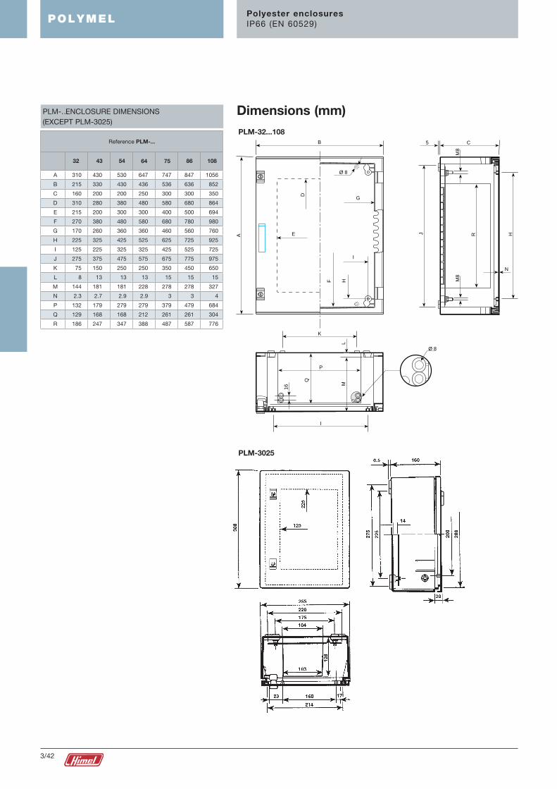
PLM-32...108
PLM-3025
POLYMEL Polyester enclosuresIP66 (EN 60529)
Dimensions (mm)
5 C
N
HRJ
M8
M8
B
Ø 8
D
A E
G
I
F H
16
Q
ML
I
K
P
Ø 8
PLM-… ENCLOSURE DIMENSIONS (EXCEPT PLM-3025)
Reference PLM-...
32 43 54 64 75 86 108
A 310 430 530 647 747 847 1056
B 215 330 430 436 536 636 852
C 160 200 200 250 300 300 350
D 310 280 380 480 580 680 864
E 215 200 300 300 400 500 694
F 270 380 480 580 680 780 980
G 170 260 360 360 460 560 760
H 225 325 425 525 625 725 925
I 125 225 325 325 425 525 725
J 275 375 475 575 675 775 975
K 75 150 250 250 350 450 650
L 8 13 13 13 15 15 15
M 144 181 181 228 278 278 327
N 2.3 2.7 2.9 2.9 3 3 4
P 132 179 279 279 379 479 684
Q 129 168 168 212 261 261 304
R 186 247 347 388 487 587 776
03_040_050_EN.indd 4203_040_050_EN.indd 42 2/4/08 12:50:142/4/08 12:50:14

355 165
200405
800
130
200
160�100
160�100165
251
398/635148
185
3/43
For the protection of cabling of outdoor installations, distribution panels for campgrounds, leisure harbours, etc. at which it is necessary to maintain a distance between the installation and the floor. Manufactured with fibreglass-reinforced polyester.
c Steel frame for fixing to the floor.
c Easy installation.
c High impact resistance.
Floor fixing using a frame (1)
Fixing to the enclosure
Floor-mounting pillar
PLM-54 SFS/PLM
PLM-64
ReferenceFor attachment to enclosures
(1) Frame supplied
For the lateral or vertical coupling of two enclosures.
c Made of fibreglass-reinforced self-extinguishing polyester.
c Sealing gasket built in, which guarantees the IP66 degree of protection.
c Mounting with screws (included in the standard supply).
Enclosure fastening ties
PLM-75 y 86 lateral BU/PLM
PLM-108 lateral BU-108/PLM
ReferenceType of couplingFor attachment to enclosures
POLYMEL Composition accessories
03_040_050_EN.indd 4303_040_050_EN.indd 43 2/4/08 12:50:142/4/08 12:50:14

15H1
V2H2
V1
8*
* For PLM-32 modeland PFI/PLM
3/44
Plain polyester cable entry plates, with sealing gasket and fastening hardware.
Cable entry plate
PLM-75/86/108 TLA-4420
PLM-108 TLA-6420
ReferenceFor attachment to enclosures
Composition accessories
Wall fixing can be done directly by drilling the back of the enclosure or with the PF/PLM polyester brackets or PFI/PLM stainless steel brackets. The brackets are mounted from the exterior to the back of the enclosure, using inserts and M8 screws (included in the standard supply).
Model PLM-32 is mounted using self-tapping screws.
The fixing pieces can be positioned vertically or horizontally.
The set is not included in the standard supply of the enclosure.
PFI/PLM
PF/PLM PFI/PLM
Wall fixing
Insulated
For attachment to enclosures
Stainless steel
Reference Horizontal position Vertical position
Fixing centres (mm)
Height (H1) Width (H2) Height (V1) Width (V2)
PLM-32 PF/PLM-32 - 247 239 334 152
PLM-3025 PF/PLM - 275 355 410 220
PLM-43 PF/PLM PFI/PLM 355 360 490 225
PLM-54 PF/PLM PFI/PLM 455 460 590 325
PLM-64 PF/PLM PFI/PLM 555 465 690 330
PLM-75 PF/PLM PFI/PLM 655 565 790 430
PLM-86 PF/PLM PFI/PLM 755 665 890 530
PLM-108 PF/PLM PFI/PLM 955 885 1090 750
POLYMEL
03_040_050_EN.indd 4403_040_050_EN.indd 44 2/4/08 12:50:162/4/08 12:50:16

B
A
3/45
Composition accessories
Allows the enclosure to be fixed to concrete, wood or aluminium posts up to diameters of 675 mm.
c For exterior installations, provisional works or fairs, public lighting panels, etc.
c Galvanised steel fixing loop and profiles.
c Profiles attach to the back of the enclosure using M8 screws in the inserts (included in the standard supply).
c Recommended maximum weight of the installation: 100 kg.
Post fixing set
PLM-43 SFP-300
PLM-54 and PLM-64 SFP-400
PLM-75 SFP-500
PLM-86 SFP-600
PLM-108 SFP-800
ReferenceFor attachment to enclosures
Internal door set in fibre-glass reinforced polyester, except model PI-3025/PLM, made of sheet steel finished with polyester-epoxy RAL-7032 paint.
Insulating door specifications:
c Self-extinguishing.
c Grid pattern on the inside of the door for alignment of equipment.
c Quick locking through 1/4 turn sealable screws.
c Door opens in both directions.
C
D
* Plain internal door, dimensions A and B corresponding to the usable surface of the door.
Internal doors
PI-3025/PLM* 248 165 62 76
PIP-43 315 205 152 26
PIP-54 415 305 152 26
PIP-64 515 305 194 32
PIP-75 615 405 244 32
PIP-86 715 505 244 32
PIP-108 850 650 269 37
Reference A B C D
POLYMEL
03_040_050_EN.indd 4503_040_050_EN.indd 45 2/4/08 12:50:172/4/08 12:50:17

3/46
Doors to be changed or repositioned on PLM enclosures.
c Made of fibreglass-reinforced self-extinguishing polyester in grey RAL-7032.
c For maximum usable surface, the plain door has a grid pattern for centring components.
c Door opening to > 180°.
Spare doors
PLM-3025 PUPLM-3025 KTPLM-3025
PLM-43 PUPLM-43 KTPLM-43
PLM-54 PUPLM-54 KTPLM-54
PLM-64 PUPLM-64 KTPLM-64
PLM-75 PUPLM-75 KTPLM-75
PLM-86 PUPLM-86 KTPLM-86
PLM-108 PUPLM-108 KTPLM-108
TransparentPlain
For attachment to enclosuresType of door
Composition accessories
Locks up to PLM-86
Standard double bar lock, with zinc-alloy inserts, operation with LDB 5 or DBP wing key (conforming to DIN 43668).
Reference: CDB/PLM.
TRANSFORMING INSERT OF STANDARD LOCK INTO STANDARDISED VERSIONS
Specifications ReferenceType of key operation ref.
v 6 mm square lock LC-7 TC6/CRN
v 7 mm square lock LC-7 TC7/CRN
v 8 mm square lock LC-8 TC8/CRN
Triangle lock with ∆ 6.5 mm side LT-8 TT7/CRN
Triangle lock with ∆ 8 mm side LT-8 TT8/CRN
Handle lock with 405 key
TL/PLM
Handle lock with key 220
TL220/PM
Stainless steel padlocking
device (up to PLM 86) KPLM
Fixed wing lock CDB/PLM
Double bar wing
DBP
Locks for polyester enclosures
POLYMEL
03_040_050_EN.indd 4603_040_050_EN.indd 46 2/4/08 12:50:182/4/08 12:50:18

3/47
Composition accessories
Four-point locks for PLM-108
Standard double-bar lock for model PLM-108 in its plain door and KT transparent door versions. Operation with LDB 5 key or DBP wing key (conforming to DIN 43668).
TRANSFORMATION FROM FOUR-POINT LOCK TO DIFFERENT TYPES OF LOCKS OR FOR ENCLOSURES
Specifications ReferenceType of key operation ref.
v 6 mm square lock LC-7 TC 6/PL
v 7 mm square lock LC-7 TC 7/PL
v 8 mm square lock LC-8 TC 8/PL
Triangle lock with ∆ 7 mm side LT-8 TT 7/PL
Triangle lock with ∆ 8 mm side LT-8 TT 8/PL
Padlocking device BC/PL
STANDARD TRANSFORMATION FOR PLM-108 ENCLOSURE RETRACTABLE HANDLE LOCK WITH DIFFERENT TYPES
Specifications ReferenceType of key operation ref.
Double bar lock LDB 5 TEDB/PL
v 6 mm square lock LC-7 TEC 6/PL
v 7 mm square lock LC-7 TEC 7/PL
v 8 mm square lock LC-8 TEC 8/PL
Triangle lock with ∆ 7 mm side LT-8 TET 7/PL
Triangle lock with ∆ 8 mm side LT-8 TET 8/PL
Lock with key type 405 TEL/PL
Key-operated Lock
Reinforced type TER/PL
Lock with JIS key
TEL-JIS/PL
Lock with FAC key
TEL-FAC/PL
Manual lock TEM/PL
Handle without lock TE/PL
Padlocking device
BCME/PL
Handle for PLM-108 TEM/PL
LOCKS (INSERTS) FOR PLM...CME ENCLOSURES
Specifications ReferenceType of key operation ref.
Double bar lock LDB 5 TDB/PLD
Triangle lock with ∆ 8 mm side LT-8 TT7/PLD
Lock with key type 405 TCL/PLD
Key-operated Lock TLR/PLD
Reinforced type
Key-operated Lock
TJIS/PLD
Padlock lock
BCME/PL
Manual lock TEM/PLD
PLM... CME locks
POLYMEL
Standard handle locks without insert in models PLM… CME.
03_040_050_EN.indd 4703_040_050_EN.indd 47 2/4/08 12:50:212/4/08 12:50:21

3/48
For attachment to enclosures
Metal
Insulated
Perforated Universal
Bakelite Polyester
Height(A)
Width(B)
P S ReferenceThickness
(mm)Weight
(kg)Reference
Thickness(mm)
Weight(kg)
ReferenceThickness
(mm)Weight
(kg)Reference
Thickness(mm)
Weight(kg)
Reference D E
310 215 265 150 MM-32 2 0.6 MB-32 4 0.2 MP-32 4 0.3 MF-32 2 0.3 MR-32 255 154
308 255 265 200 MM-3025 2 0.6 MB-3025 4 0.3 MP-3025 4 0.4 MF-3025 2 0.5 MR-3025 253 228
430 330 365 250 MM-43 2 1.6 MB-43 4 0.5 MP-43 4 0.7 MF-43 2 1.5 MR-43 348 251
530 430 465 350 MM-54 2 2.5 MB-54 4 0.9 MP-54 4 1.2 MF-54 2 2.4 MR-54 450 351
647 435 565 350 MM-64 2 3.1 MB-64 4 1.1 MP-64 4 1.4 MF-64 2 3 MR-64 555 351
747 536 665 450 MM-75 2 4.6 MB-75 4 1.7 MP-75 4 2.1 MF-75 2 4.3 MR-75 645 451
847 636 765 550 MM-86 2.5 9.9 MB-86 4 2.3 MP-86 5 3.8 MF-86 2.5 9 MR-86 750 551
1056 812 965 750 MM-108 2.5 16.9 MB-108 5 5.7 MP-108 5 6.5 MF-108 2.5 16 MR-108 945 751
Mounting accessoriesPOLYMEL
A complete range of mounting plates comprised of 4 versions able to provide all the mountings required for this installation system.
c Metal plates of galvanised sheet steel.
c Microperforated plates made of galvanised sheet steel with 3.6 mm ∅ holes, 12.5 mm apart.
c Universal perforated plates for fast fixing of equipment, made of zinc steel.
c Insulating bakelite or polyester plates.
E
D
15
12,5
P
S
10,5 10,5
12,5 25 25
2525
20
B-75
A-7
5
ø6,5
ø8,5
P
S
12,5
P
S
B-75
A-7
5
12,5
12,5
12,5
12,5
ø3,6
P
S
Metal BakelitePerforated UniversalMetal
Bakelite
Microperforated
Universal perforated
Mounting plates
Polyester
Polyester
03_040_050_EN.indd 4803_040_050_EN.indd 48 2/4/08 12:50:262/4/08 12:50:26

B
A
11�26 mm
30 30
1515
3/49
Mounting accessoriesPOLYMEL
Supports designed to fit 200, 250, 300 and 350 mm deep enclosures.
With positioning notches along its entire length for depth adjustment of the mounting plate every 12.5 mm.
c Made of galvanised sheet steel.
c Quick fixing to the enclosure.
Adjustable plate support
PLM-43 and 54 DPLM-200 156 94
PLM-64 DPLM-250 200 100
PLM-75 and 86 DPLM-300N 250 100
PLM-108 DPLM-350 306 106
For attachment to enclosures Reference A B
Fixing accessories for universal plates
Length(mm)
Fixing nut Fixing screw with washer
Thread typePackaging Packaging
M3 TFP 3 100 - - -
M4 TFP 4 100 TOR 10/4 A 10 100
TOR 16/4 A 16 100
M5 TFP 5 100
TOR 12/5 A 12 100
TOR 18/5 A 18 100
M6 TFP 6 100
TOR 12/6 A 12 100
TOR 18/6 A 18 100
03_040_050_EN.indd 4903_040_050_EN.indd 49 2/4/08 12:50:272/4/08 12:50:27

25
3/50
Mounting accessoriesPOLYMEL
c Insulating support and self-tapping screw for quick fixing of L brackets and 35 mm symmetrical rails (Ref. TCO/PLM).
c Insulating support and M6 inserted bolt for quick fixing of L brackets and 35 mm symmetrical rails (Ref. TCO-M6/PLM).
Rail fixing set
TCO/PLM Self-tapping
TCO-M6/PLM M6
Type of screwReference
35 mm symmetrical rails to support equipment, specially adapted to the width of the enclosures.
Fixing at the back of the enclosure using the TCO/PLM set.
35 mm symmetrical rail
PLM-32 CO-200/PLM 180
PLM-43 CO-300/PLM 280
PLM-54 and 64 CO-400/PLM 380
PLM-75 CO-500/PLM 480
PLM-86 CO-600/PLM 580
PLM-108 CO-800/PLM 795
For attachment to enclosures Reference Width
TCO/PLM
03_040_050_EN.indd 5003_040_050_EN.indd 50 2/4/08 12:50:292/4/08 12:50:29

3/51
Current distribution accessoriesPOLYMEL
Clip in fasteners to be installed directly on 19” racks and on slotted MR mounting plates.
Reference: GCR.
GCR ties
Made of 6.6 nylon in natural colour or black for outdoor conditions.
Adjustable ties
White BlackL ∅
minimum∅
maximum
M
Reference Use
LZ25100 LN25100 100 2.5 1.6 22
LZ25200 LN25200 200 2.5 1.6 49
LZ35150 LN35150 150 3.5 1.6 35
LZ35200 LN35200 200 3.5 1.6 49
LZ35300 LN35300 300 3.5 1.6 75
LZ46150 LN46150 150 4.6 1.6 36
LZ46200 LN46200 200 4.6 1.6 49
LZ48270 LN48270 270 4.8 1.6 73
LZ46390 LN46390 390 4.6 1.6 109
LZ76390 LN76390 390 7.6 4.7 108
To tighten and cut to size the adjustable ties. They facilitate wiring and save time, preventing the packets of cables from loosening.
Tool adjustable according to the thickness of the tie. Can be used with the following models: LZ25100 up to LZ46390. Ref.: MARK3.
A very light and ergonomic tool, the cut on the tie is done by twisting the tool. Can be used on the following models of ties: LZ25100 up to LZ46390. Ref.: MARK20, 21.
Tightening tools
Reference
MARK3 2.5 ÷ 4.8
Admissible width ties
Reference
MARK20 2.5 ÷ 4.8
MARK21 4.6 ÷ 7.6
Admissible width ties
03_051_062_EN.indd 5103_051_062_EN.indd 51 2/4/08 12:51:542/4/08 12:51:54
3/52
Current distribution accessoriesPOLYMEL
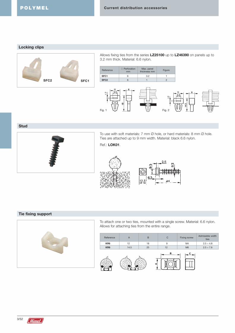
To use with soft materials: 7 mm Ø hole, or hard materials: 8 mm Ø hole. Ties are attached up to 9 mm width. Material: black 6.6 nylon.
Ref.: LOK01.
Stud
To attach one or two ties, mounted with a single screw. Material: 6.6 nylon. Allows for attaching ties from the entire range.
Tie fixing support
Reference A B Fixing screwAdmissible width
tiesC
KR6 12 18 9 M4 2.5 ÷ 4.8
KR8 14.5 25 12 M6 2.5 ÷ 7.6
Allows fixing ties from the series LZ25100 up to LZ46390 on panels up to 3.2 mm thick. Material: 6.6 nylon.
Locking clips
Reference
SFC1 6 3.2 1
SFC2 6 1 2
FigureMax. panel
thickness mm∅ Perforation
mm
SFC2 SFC1
Fig. 1 Fig. 2
03_051_062_EN.indd 5203_051_062_EN.indd 52 2/4/08 12:51:552/4/08 12:51:55

adhesive support
3/53
Current distribution accessoriesPOLYMEL
To transform normal ties into ties with fixing heads, introduce a tie into this head before closing it on the cable bundle. Material: 6.6 nylon.
Support heads
Reference A B Fixing screwAdmissible width
tiesC
FH18 7.1 13.3 4 M4 2.5
FH30 9.5 17.9 4.7 M5 3.5
FH50 11.3 22.2 6.2 M6 4.7
Permits insertion of 1 tie from 4 points at a 90º angle. Attaches ties from the series LZ25100 up to LZ46390. Material: 6.6 nylon.
Self-adhesive support base
Reference A B C EAdmissible width
tiesD
MB3A 19.1 19.1 4.8 3.2 13.2 2.5 ÷ 3.5
MB4A 28.5 28.5 5.5 4 20.2 2.5 ÷ 4.8
To attach ties from any series. Material: 6.6 nylon.
Tie fixing support
Reference
LKC 2.5 � 7.6 M5
Fixing screwAdmissible width
ties mm
03_051_062_EN.indd 5303_051_062_EN.indd 53 2/4/08 12:51:572/4/08 12:51:57

3/54
Current distribution accessoriesPOLYMEL
2 versions, fixed and graduated, ∅ from 5 to 25.4 mm. Material: black 6.6 nylon.
Fixing loop for tubes, hoses, etc.
Reference∅ A
min. - max.B D EC
NX1 5 3.5 1 6.2 13.7
NX3 8 3.9 1 9.4 20.5
NX5 12 3.9 1 9.4 24
NX8* 14.3 ÷ 15.8 4 1.3 12.6 32
NX11 17.4 ÷ 20 4 1.3 12.6 37
NX14 22.2 ÷ 25.4 4.3 1.5 16 45
*The NX8 model only has 3 adjustment holes.
NX 1-3-5 NX 8-11-14
Covers the head of the tie in its end, thus obtaining neater cabling. Material: 6.6 nylon.
Lateral tie fixing support
Reference
LKM/HE 2.5 � 7.6 M5
Fixing screwAdmissible width
ties mm
03_051_062_EN.indd 5403_051_062_EN.indd 54 2/4/08 12:51:582/4/08 12:51:58

Ø A
Ø B
3/55
Current distribution accessoriesPOLYMEL
Insulating membrane glands made of PVC with entry that can be adjusted for cables.
Adjustable membrane glands
Reference Fig. Ø A Ø B* Ø C Ø D E FØ cable Tube
Capacity
ECPC-3 1 25 21.5 18 5 3.2 13 5 to 18 Pg 9 to 11
ECPC-5 1 33 29.5 26 5 3.2 20 5 to 26 Pg 9 to 16
ECPC-6 1 43 38.5 36 5 3.2 22 5 to 36 Pg 9 to 21
ECPC-9 2 70 63 60 28 3 20 28 to 60 Pg 21 to 48
ECPC-15 2 98 90 87 28 3 23 28 to 87 Pg 21 to 48
* Mounting perforation.
Fig. 1 Fig. 2
Small protective sleeves for cables coming out of tubes, as indicated in the instructions for MI BT 019. Made of flexible and durable PVC, in light grey colour.
Protective sleeves
Reference A Ø B Tube
PC-1 15.2 12.7 Pg 9
PC-2 18.6 16 Pg 11
PC-3 20.4 17.8 Pg 13.5
PC-4 22.5 19.8 Pg 16
PC-5 28.3 25.3 Pg 21
PC-6 37 33.6 Pg 29
PC-7 47 43 Pg 36
03_051_062_EN.indd 5503_051_062_EN.indd 55 2/4/08 12:51:592/4/08 12:51:59

3/56
Current distribution accessoriesPOLYMEL
Øexterior
SteelFlexible
steelPVC Insert Thread
Protective sleeves
Adjustable membrane
glandsPlain plugs
Adjustable membrane glands
Flexible steel with
PVC
Cables inserted*Ø interior To the perforationsTo the tubes
4 EC-1 to EC-7
Pg 9 15.2 12.7 12.4 12 11.1 6 2.5 - - 16 14 ECPC-3 to ECPC-6 PC-1 - -
ECN-5 to ECN-10
10 4 2.5 EC-2 to EC-7 EC-1
Pg 11 18.6 16 15.5 14.5 14.2 16 6 4 2.5 19 17.5 ECPC-5; ECPC-6 PC-2 EC-2 TC-1
25 ECN-5 to ECN-10 ECN-1
EC-3 to EC-7 EC-3
Pg 13.5 20.4 17.8 17.5 16.3 16 35 10 6 4 21 19.5 ECPC-5; ECPC-6 PC-3 ECPC-3 TC-2
ECN-5 to ECN-10
EC-4 to EC-7
Pg 16 22.5 19.8 18.7 18.5 17.6 50 16 10 6 23 21.5 ECPC-5; ECPC-6 PC-4 EC-4 TC-3
ECN-5 to ECN-10
EC-5 to EC-7 EC-5
Pg 21 28.3 25.3 24.7 23 23 70 25 16 10 29 27 ECPC-6 to ECPC-15 PC-5 ECPC-5 TC-4
ECN-6 to ECN-10 ECN-5
95 35 25 16 EC-6; EC-7 EC-6 TC-5
Pg 29 37 33.6 33.5 31 31 120 50 35 25 38 35.5 ECPC-9; ECPC-15 PC-6 ECPC-6 TCP-5
150 ECN-7; ECN-10 ECN-6
185 35 EC-7 EC-7
Pg 36 47 43 41.5 41 40.3 240 70 50 50 48 45.5 ECPC-9; ECPC-15 PC-7 ECN-7 TC-6
300 ECN-10
95 70 ECPC-9; ECPC-15
Pg 42 54 50 48 48 47 - 120 95 70 55 52.5 ECN-10 - - -
120 95 ECPC-9; ECPC-15
Pg 48 60 56 54.2 52.5 51.4 - 150 150 120 61 58 ECN-10 - - -
* Number and section in mm2 of the conductors that may be housed inside each tube (orientative).
For more information, consult the electrotechnical rules for low voltage (MI BT 019).
1 2 3 4
MODELS, DIMENSIONS AND REFERENCES
No. of conductors
Tubes HIMEL accessories to be coupled
Useful information about Pg tubes and HIMEL accessories to be coupled
Ø perforations to
Desig-nation
03_051_062_EN.indd 5603_051_062_EN.indd 56 2/4/08 12:52:002/4/08 12:52:00

3/57
Current distribution accessoriesPOLYMEL
Base of safety terminals made of black matte self-extinguishing polyamide-6; terminal of brass MS-58.
(DIN17660); ring of tempered steel zinc dichromate; cap made of orange self-extinguishing polypropylene.
c Anti-cut. The connection is made using a tightening mechanism that spreads the pressure out throughout the entire contact surface, avoiding the occasional rubs and stresses that damage the conductors.
c Loosening proof. The ring that surrounds the brass body ensures that the pressure exerted by the conductors cannot open the terminal and loosen the connection.
c Total insulation. All the SIGMA terminals are supplied with a terminal cap, avoiding any accidental contact with live parts.
All the calibres may be coupled one to the other, allowing the formation of strips of any length. Service voltage: 500 V.
Sigma safety terminals
Reference
S.04 1 × 4 30 20 13 21 4
S.06 1 × 6 33 25 16 24 7
S.10 1 × 10 38 28 16 28 6
S.16 1 × 16 42 32 19 32 9
S.25/35 1 × 35 46 38 23 34 11
S.50 1 × 50 52 45 27 40 15
S.70 1 × 70 55 50 30 40 15
S.95/100 1 × 100 58 54 33 40 20
NOTE: each terminal accepts up to 2 conductors of the section indicated.
Section m/m2 A B C D E
* Included in standard supply.
Number of terminals � section in mm2
Earth and neutral bypass terminal blocks with insulated plinth.
Direct fixing by pressure on the profile supplied by the chassis itself.
Bypass terminal blocks
RBLZ/21656* 2�16 mm2 + 5�6 mm2
RBLZ/21686 2�16 mm2 + 8�6 mm2
RBLZ/216146 2�16 mm2 + 14�6 mm2
RBLZ/216296 2�16 mm2 + 29�6 mm2
Reference
03_051_062_EN.indd 5703_051_062_EN.indd 57 2/4/08 12:52:002/4/08 12:52:00

1 2
3/58
Current distribution accessoriesPOLYMEL
Terminals especially designed for branching cables on plates; their main application is busbar connection.
BBH terminals are made of a tinned, hot cast copper alloy and are suitable for connecting to a conductor of copper or aluminium indistinctly (bimetal).
Bimetal BBH terminals
Reference
BBH-29 6-50 -
BBH-29C* 6-50 -
BBH-30 10-95 -
BBH-31 16-150 -
BBH-32 50-240 -
BBH-29D 6-50 6-50
BBH-29DC* 6-50 6-50
BBH-30D 10-95 10-95
BBH-31D 25-150 16-150
BBH-32D 95-240 5-240
Main section mm2 Bypass section mm2
Reference
BBH-29P 6-50 -
BBH-29PC* 6-50 -
BBH-29DP 6-50 6-50
BBH-29DPC* 6-50 6-50
* Include terminal cover CBBH-29.
Main section mm2 Bypass section mm2
BBH-29 BBH-29D
BBH-29P BBH-29DP
Plate entry and bypass by cable.
Plate/cable terminals
ReferenceCable bypass section
(mm2)Plate thickness (mm) Figure
BPCH 516 1.5 to 16 5 2
BPCH 550 1.5 to 50 5 2
BPCH 5120 16 to 120 5 2
BPCH 1016 1.5 to 16 10 1
BPCH 1050 1.5 to 50 10 1
BPCH 10120 16 to 120 10 1
03_051_062_EN.indd 5803_051_062_EN.indd 58 2/4/08 12:52:042/4/08 12:52:04

35590
7066
3/59
Lighting accessoriesPOLYMEL
Compact lamp
Specifications TensionPlugReference
Lamp fixed with a magnet or
on 35 mm symmetric LAM-75 220 V/16 A 220 V/50 Hz
DIN rail.
Lamp fixed on a 35 mm
symmetric DIN rail. LAC-75 220 V/16 A 220 V/50 Hz
Lamp fixed with a magnet
or on 35 mm symmetric LAM-75/120 120 V/15 A 120 V/60 Hz
DIN rail.
Lamp fixed on a 35 mm
symmetric DIN rail. LAC-75/120 120 V/15 A 120 V/60 Hz
Compact fluorescent lamps, designed especially for use in electronic enclosures. May be fixed with a magnet.
c Connection voltage 220 V/50 Hz.
c Consumption 11 W.
c Connection/disconnection switch.
c 200 V/16 A socket with earthing.
c Maximum ambient temperature 60 °C.
c Lighting output = 75 W bulb.
Magnetic-fixing flat lamps equipped with energy efficient light bulbs, with or without a plug.
c Electronic ballast.
c Power: 11 W.
c Luminosity: 900 lm.
c Lifespan: 10000 h.
c Plastic casing UL94 V0.
c IP20.
c Class I.
Slimline lamp
Reference Plug Socket Approval
LAMS75 AC 230 V/16 A SCHUKO VDE
LAMX75 AC 230 V/- - VDE
LAMU75 AC 120 V/15 A USA UL
03_051_062_EN.indd 5903_051_062_EN.indd 59 2/4/08 12:52:062/4/08 12:52:06

396
67
100
500
3/60
Lighting accessoriesPOLYMEL
Dual lamp
1
2
3
4
Specifications Support fixing Figure Reference Tension
Motion-activated
Magnetic, using screws LAMDP 220 V/56 Hz
and/or (1) 35 DIN rail 1 LAMDP 120 120 V/60 Hz
On/off switch with the possibility Magnetic, using screws LAMIN 220 V/50 Hz
of connection of door switch and/or (1) 35 DIN rail 2 LAMIN 120 120 V/60 H
Mobile lamp, connection Adhesive or screws
LAMPO 220 V/50 Hz
via cable 3 LAMPO 120 120 V/60 Hz
Support for LAMDP, LAMIN, Adhesive or screws
LAMPO lamp 4 SOLAM
(1) DIN rail not provided.
Light fixtures designed especially for use in electronic enclosures with various possibilities for fixing and operating.
c Energy efficient electronic lamp E27, 20 W, 220-240 V/50-60 Hz or 120 V/60 Hz.
c Lighting output = 100 W bulb.
c Fixed models connection via 2.5 mm2 terminal strip and the mobile model via cable.
c Degree of protection IP20.
c Insulation class II.
c Conforming to EN 55014 and EN 50082-1.
Incandescent lamp designed especially for use in electronic enclosures.
c Connection voltage 220 V/50-60 Hz.
c Consumption 60 W.
c Connection/disconnection switch.
c Terminal connection entry.
Incandescent lamp
Reference
LAI/OL 68
03_051_062_EN.indd 6003_051_062_EN.indd 60 2/4/08 12:52:072/4/08 12:52:07

3/61
Natural ventilation accessoriesPOLYMEL
To connect the inside of the enclosure with the exterior atmosphere and prevent condensation. Can be fixed onto the outside, Ref.: VM-25 and VM-27 or onto the internal sides connected with the rear self-ventilating windows of the POLYMEL enclosures, Ref.: VM-35.
VM-25 VM-27
VM-35
Ventilation devices
VM-25 For coupling to the outside of all polyester enclosures
VM-27
VM-35 For coupling to the interior of POLYMEL enclosures
SpecificationsReference
To remove condensation water.
Mounted on the ∅ 9 mm housing on the inside of the bottom of the enclosure. Degree of protection IP55.
Purging device
VEA-9 For attachment to all enclosures
SpecificationsReference
Rear blanking plates in insulating material to protect against unwanted elements entering into the self-ventilating window of the enclosure.
Not included in standard supply with the enclosure except for model 108 which has it built in.
Rear blanking plates
PLM-32 CE-PLM/A
PLM-43 and 54 CE-PLM/B
PLM-64, 75 and 86 CE-PLM/C
ReferenceFor attachment to enclosures
03_051_062_EN.indd 6103_051_062_EN.indd 61 2/4/08 12:52:092/4/08 12:52:09

174
188 22 278 40
234
3/62
Complementary accessoriesPOLYMEL
Dodge-type brass nuts designed to be incorporated into the bosses of PLM enclosures.
Expandable nuts
M5 PLM-43 and 54 TEX 5
M6 PLM-64 and 108 TEX 6
M8 For the back of the enclosure TEX 8
ReferenceSpecifications For attachment to enclosures
PP-A models made of thermo-plastic in grey RAL-7035.
c Fixed with adhesive tape or screws.
For holding A4 or A5-sized plans.
Document pocket
Ref.: PP-A5 Ref.: PP-A4
Plan size
A4 PP-A4
A5 PP-A5
Reference
Insulated
TEX 8 TEX 6 TEX 5
03_051_062_EN.indd 6203_051_062_EN.indd 62 2/4/08 12:52:102/4/08 12:52:10

3/63
c Rigid structure made of galvanised steel.
c Insulating cover and frame in self-extinguishing material in RAL-7035.
Quick mounting, without the need for screws.
c System for identifying circuits included in the standard supply.
c Earth and neutral bypass terminal blocks. Ref.: RBLZ/21656 (included in
standard supply).
PLM-64/KT + DLA-48P
POLYMEL Applications
Distribution chassis set for modular equipment, Ref.: DLA-... with a distance between the 35 mm symmetric profile and the cover, which is adjustable as needed by the customer from 40 to 85 mm.
Dinimel DLA distribution chassis
03_063_067_EN.indd 6303_063_067_EN.indd 63 2/4/08 12:52:592/4/08 12:52:59

3/64
* Models DLA-48P, 66, 88, 84 and 112.
POLYMEL Applications
Dimensions (mm)
DLA-24 DLA-48 DLA-48P DLA-66 DLA-88
DLA-84 DLA-112 DLA-240
* For PLM.../CME enclosures with three-point locks, factory assembly
To be coupled to enclosures*
Reference
Plain door Transparent door No. of rowsQuantity
No. of 18 mm modules
Distribution of rows
Automatic rail
No. of plates A B
Dimensions
C D min. E min.
PLM-3025 PLM-3025/KT DL/PLM18 2 2 18 - - - - - -
PLM-43 PLM-43/KT DLA-24 2 2 24 - 216 115 137 38 88
PLM-54 PLM-54/KT DLA-48 3 3 48 - 288 90 112 38 88
PLM-64 PLM-64/KT DLA-48P 3 3 48 - 288 140 170 80 130
PLM-75 PLM-75/KT DLA-66 4 3 66 1 395 115 145 129 179
PLM-75 PLM-75/KT DLA-88 4 4 88 - 395 115 145 129 179
PLM-86 PLM-86/KT DLA-84 4 3 84 1 504 165 195 129 179
PLM-86 PLM-86/KT DLA-112 4 4 112 - 504 165 195 129 179
PLM-108 PLM-108/KT DLA-240 6 6 234 - 704 115 146 170 220
03_063_067_EN.indd 6403_063_067_EN.indd 64 2/4/08 12:53:002/4/08 12:53:00

3/65
Insulating cover in self-extinguishing material in RAL-7035 to protect non-modular equipment. Height: 150 mm (1 row).
Plain Dinimel DLA cover
DLA-24 CTL300/DLA 256
DLA-48 and 48P CTL400/DLA 356
DLA-66 and 88 CTL500/DLA 456
DLA-84 and 112 CTL600/DLA 555
DLA-240 CTL800/DLA 755
ReferenceReferenceTo be coupled to chassis
POLYMEL Applications
Mounting plate in galvanised steel for fixing non-modular equipment. Height: 150 mm (1 row).
Dinimel DLA mounting plate
DLA-24 PMP300/DLA 215
DLA-48 and 48P PMP400/DLA 315
DLA-66 and 88 PMP500/DLA 415
DLA-84 and 112 PMP600/DLA 514
DLA-240 PMP800/DLA 714
WidthReferenceTo be coupled to chassis
Blanking plate of self-extinguishing insulating material for total or partial coverage of the windows for automatic switches. Easily cut to the desired size.
Blanking plate
ATP6/DTM 108 6
ATP24/DTM 432 24
ATP/UND 1100 Cut to size
No. of modulesLength (mm)Reference
03_063_067_EN.indd 6503_063_067_EN.indd 65 2/4/08 12:53:012/4/08 12:53:01

3/66
* Included in standard supply.
Number of terminals 3 section in mm2
Earth and neutral bypass terminal blocks with insulating plinth.
Direct fixing by pressure on the profile supplied by the chassis itself.
Bypass terminal blocks
RBLZ/21656* 2�16 mm2 + 5�6 mm2
RBLZ/21686 2�16 mm2 + 8�6 mm2
RBLZ/216146 2�16 mm2 + 14�6 mm2
RBLZ/216296 2�16 mm2 + 29�6 mm2
Reference
POLYMEL Applications
For the distribution in a single row of automatic switches with a total of 12 modules.
1 2
3 4
Distribution bars
No. of bars No. of poles per bar Reference Figure No.
1 12 BDS 1/12 1
2 6 BDS 2/6 2
3 4 BDS 3/4 3
4 3 BDS 4/3 4
03_063_067_EN.indd 6603_063_067_EN.indd 66 2/4/08 12:53:012/4/08 12:53:01

3/67
POLYMEL Applications
Due to the quality of the plastic materials and their constructive characteristics, POLYMEL enclosures are suitable for panels in installations subjected to contact with chemical agents and harsh environments, usually, for example, in the petrochemical, cement making, etc. industries.
Their resistance to corrosion and UV rays permits POLYMEL enclosures to be adapted to panels in exterior installations subjected to long exposures to the sun: winter sport stations, installations close to the sea, etc.
POLYMEL enclosures in leisure facilities
Their high degree of protection (IP66) and their high resistance to impacts and temperature make POLYMEL enclosures particularly ideal for industrial installations subjected to processes with frequent water projection, such as the paper-making and agri-food industries or automobile washes.
POLYMEL enclosures in interior industrial installations
POLYMEL enclosures in exterior industrial installations
03_063_067_EN.indd 6703_063_067_EN.indd 67 2/4/08 12:53:052/4/08 12:53:05