polygonmap help contents
TRANSCRIPT
PolygonMap Help
Contents
Introduction 2One poly mapping 3Parameters Rollout 5Link Rollout 10Transform Rollout 13Slice Rollout 14Viewport Rollout 14Junction point 15Additional info 16Mapping creation procedure 17Examples of mapping 18
Author Gushchin Nikit (aka NiK)

Here will be described version 5.7 of PolygonMap plugin, but most of information will be actu-al for older and newer versions too.
You can buy it here.
For many of 3d-workers mapping is one of the most complicated stage of work. Generally, standart presets of mapping like Box of Cylindrical is enough for many of objects. For more complex objects user needs to use Unwrap UVW modifier, that can be a little difficult to set up. PolygonMap plugin can align texture on polygon to one of its edges, apply all transforma-tions to mapping, and most important thing is creating links between polygons so next poly can inherit mapping from previous. Thus, user can create seamless mapping for complex 3d objects when using of Unwrap UVW is unreasonably difficult. Below there are an examples of this kind of objects.
Introduction

You can make this mapping in less than a minute.
One poly mapping
Create a material for our object. In diffuse slot add this default PolygonMap texture.
You can copy it from this PDF file with right-click menu (you must select the image first).
So, lets start from simple example and make mapping for just one polygon. Create 1 meter Plane with 1 segment and add PolygonMap modifier. In Width field enter value of 1 meter, by the size of our poly.

Every texture has its coordinates, X and Y axis, but it calls U and V. Horizontal (U) and vertical (V). It calls different cause user can be confused by same axis names while mapping.
Our plane has its own mapping of 1 meter size. Thus we didn’t get something new, but now we will align mapping to one of edges.
This two buttons are responsible for aligning U and V axis to any polygons edge. Green is for horizontal U, blue is for vertical V.
However, every edge has 2 points (vertex). To pick point from which tex-ture must mapped you need to click near this point, but cursor also must be near needed edge. This picture approximately shows click zones for every edge and every point. For example, to select point 5 on lower edge you must click somewhere in red zone.
So, after clicking a button with green triangle and U letter we must pick an edge on poly. Hori-zontal axis U of texture will be aligned to this edge. Picked vertex will be a zero coordinate point of texture.Button with blue triangle and V letter works absolutely same way but it aligns V axis instead of U.This picked edges further we will call “align edges”.
If you are too lazy to read description of all features, you can go directly to Mapping creation procedure chapter. It describes how to create mapping with links and align edges.

Parameters Rollout
Min len – Automatically align U axis of a texture to edge with smallest lenght.Max len – Automatically align U axis of a texture to edge with biggest lenght.
Min lenMax len
Group – Applies one mapping to all polygons. Similar to planar mapping.
Group ON
Quadrifity – PM calculate average area of polygons to create square mapping for each of them. This option can deform textures, but unwrap will be seamless.
Quadrifity OFF Quadrifity ON
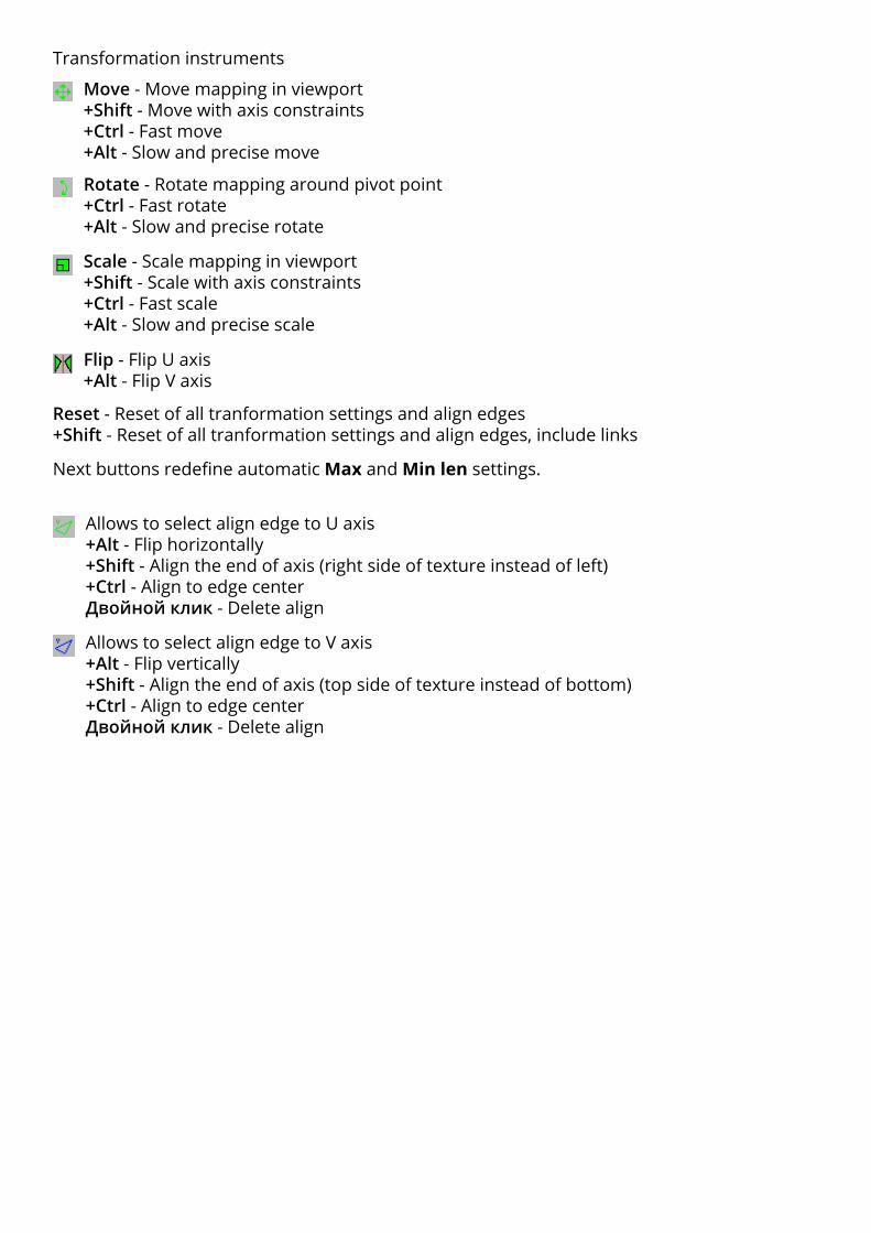
Move - Move mapping in viewport+Shift - Move with axis constraints+Ctrl - Fast move+Alt - Slow and precise move
Rotate - Rotate mapping around pivot point+Ctrl - Fast rotate+Alt - Slow and precise rotate
Scale - Scale mapping in viewport+Shift - Scale with axis constraints+Ctrl - Fast scale+Alt - Slow and precise scale
Flip - Flip U axis+Alt - Flip V axis
Reset - Reset of all tranformation settings and align edges+Shift - Reset of all tranformation settings and align edges, include links
Transformation instruments
Allows to select align edge to U axis+Alt - Flip horizontally+Shift - Align the end of axis (right side of texture instead of left)+Ctrl - Align to edge centerДвойной клик - Delete align
Allows to select align edge to V axis+Alt - Flip vertically+Shift - Align the end of axis (top side of texture instead of bottom)+Ctrl - Align to edge centerДвойной клик - Delete align
Next buttons redefine automatic Max and Min len settings.

Examples of align U axis to edges. Click zone is marked as red dot.
Texture is rotated because its beginning of coordinates aligned to bottom-right vertex (on bottom edge). Instead of flipping texture it rotates at 180 deg. Flipping of texture by simple click was removed cause of potential problems with thing like normal bump. Next tile of texture is shown under the picture.
Texture isn’t rotated because its beginning of coordinates aligned to top-left vertex (on top edge). Next tile of texture is shown above the picture.
Simple click
Alt + click - Flip axis (in this case U)
There is no need to examine all this almost similar pictures, it’s enough to understand first four of them. However, if you’ll not undestand algorithm of aligning to edges, you can find your case in this list.

Ctrl + click - Align beginning of coordinates to center of an edge
Shift + click - Align end of coordinates instead of beginning
Align of V axis done in the same manner.
Alt + Shift + click - Align end of coordinates instead of beginning with flipping
Ctrl + Shift и Ctrl + Alt also works

Pick mapping from other polygon (works with other objects too). It also copies transfor-mation settings (see chapter Transform Rollout)+Alt - Pick mapping with material
Map channel - Define map channel
Weld - On/Off weld vertexes mode. Counter define sensitivity, i.e. minimal distance between vertexes to be welded.
Weld OFF Weld ON
Get image aspect - Take aspect ratio for mapping from diffuse texture of object’s material.
Presets - List of saved presets Save - Save settings to preset Remove - Delete selected preset Apply - Apply selected preset
Pick pivot point and junction point.+Alt - Pick source point instead of junction point (see chapter Junction point).

Link RolloutHere comes most interest part.Links allows nex polygon inherit mapping of prevoius polygon. In other words - mapping on first polygon seamless continues on second and further along link.
Principle of link creation is very simple. Every two neighboring polygons has one common edge, through which link are passes. If you select polygon or link, then in UVW Space window this common edge will become yellow. Links are built like a tree.
On - Turn links on
Next - Turn on automatic alignment edges creation along link branch (see chapter Mapping creation procedure)
Counter - Control of automatic links tree0 - (Default) First branch will continue to biuld until it hit other link branch or object’s border1 - All branches will continue to build only to 1 next polygon2 - All branches will continue to build only to 2 next polygons etc.
0 - No build limit. Endless building. 1 - Biuld limit 1. Branches are built only to 1 next poly-gon.
In this example result will be similar, because links are cover whole object in right order any-way. However, in other cases this option might be useful.

Automatic - Automatic link creation mode.
First - If enabled, the first mapping is applied by automatic, and then by manual links (or base). Disabled by default.
by IDs - Generate automatic links based on Material IDs of the object. Link will break at the border of different IDs.
by smooth - Generate automatic links based on smoothing groups. Link will break at the bor-der of different smoothing groups.
by direction - Generate automatic links based on angle between: edge - edges normal - polygon normals
счетчик справа - angle on degrees
Also, the counter controls the number of link segments to ring, loop and remove commands.
Worth mentioning that a large number of parameters and options in the plugin is just due to the fact that the possible situations of mapping can be endless. For this reason, having to add many seemingly unnecessary features. You will not use them most of the time, but at some point they may prove useful.
Links selection mode. By clicking selects the entire link branch and a one polygon.+Shift - Add to selection+Ctrl - Remove from selectionДвойной клик - Select all the polygons belonging to a link branch.
To create a link you must click anywhere on the polygon and then click on next one. Con-tinue making links as needed by clicking on each next poly. Double click to finish the link and exit creation mode.+Shift (push and hold after the first mouse click) - double click will make link loop and finishes it.The following combinations make it possible to specify the alignment edges along with the links creation. This is a little more difficult, but maybe someone finds it more conven-ient and faster. Still, its more accurate to do links at first and then adjust alignment edges with tools in the Parameters rollout.
+Shift (push and hold before the first mouse click) - along with the link creation allows you to immediately make alignment edges for the U-axis along the link branch.+Shift+Alt - the same for the U-axis but in the opposite direction.+Ctrl - along with the link creation allows you to immediately make alignment edges for the V-axis along the link branch.+Ctrl+Alt - the same for the V-axis but in the opposite direction.

Selective conversion of an automatic link to the base/custom links
Partial remove mode. To remove a part of the link you need to click at first segment of this part and then continue clicking on each next segment till you reach the end.
Remove branch mode. Click anywhere at the branch to delete it.
Reset transformation - Resets the transformation and align settings like Reset button in the Parameters rollout, but applied only to polygons of the selected branches.
Get from automatic mapping - Convert all automatic links to the base links.
Loop - Loop link like edges in polygon modeling. The link is going on in it’s direction as possi-ble.
Ring - Ring link like edges in polygon modeling. The link will be copied in the perpendicular direction as long as possible.
Remove - Remove selected branch.
Select prev - Select previous branch (All branches are numbered. Branch number is shown to the right of the red delete button).
Select next - Select next branch.
Move back - Reducing the sequence number of the selected branch.Move front - Increase the sequence number of the selected branch.
Reverse - Changing the direction of the branch to the opposite.
Delete all links - Delete all base links.

Transform RolloutUse old mapping - Use existing polygon mapping.Blocks nearly all functions of PolygonMap, except for offset and angle.Break map faces - Break mapping vertices. Allowing you to do a random shift or rotate with the existing mapping. Rotate and shift can be made by Offset and Angle counters (+ Rnd).
Fit - Enable continuous automatic adjustment of the mapping size to the size of each polygon. Works only if the Links are off, because the size of polygons and mapping will be different.
Set size from fit - Adjust mapping size to polygon size. In fact this function is duplicate of the pipette (pick mapping) and F buttons near width and height parameters (see below).
Size:Aspt - Lock aspect ratio. The value determines the aspect of mapping (1.0 for a square tex-ture). In this mode, manual editing of the height mapping is not possible, it is calculated auto-matically from widht (width / aspect ratio).
A - Link width of mapping to the align edge length. Width becomes locked. Changing the height is possible.
Width - The width of mapping.F - Adjust mapping width to the width of the first polygon.Height - The height of mapping.F - Adjust mapping height to the height of the first polygon.The width and height of the polygon defined by align edges (align edge is wide, and a height perpendicular to it) or sequential numbers of the edges.Lenght - When you assign modifier it applies box mapping. In fact, you don’t need to touch this value, and it exists only for informative purposes.
Tile:U - U tiling value. Flip - opposite direction.V - The same for V axis.W - The same for W axis.
Offset:U - Offset for U axis. Rnd - Random value for each polygon limited by counter.V - The same for V axis.W - The same for W axis.
Angle - Mapping rotate angle.Rnd - Random value for each polygon limited by counter.Discr - Use only the specified value multiples. If it’s 90 specified, then the available values are 90,180,270,360. If it’s 45, then 45,90,135 etc.

Slice Rollout
On - Включить режим нарезанияPreview - Включить/выключить предпросмотр. При включённом предпросмотре нарезка не производится, только демонстрируется. Чтобы сделать нарезку нужно отключить эту галочку.Old map - Использовать для нарезки уже имеющийся на полигонах маппинг.Fissure - Размер шва между нарезанными полигонами.
Начиная с версии 5.7Для работы следующих опций необходимо снять галочку Preview.Nothing - (По умолчанию) оставить швы как есть.Split - Отделить швы от основого объекта на уровне элементов.Delete - Удалить швы.Set ID - Назначить Material ID для швов.
В этом свитке можно настроить нарезание полигонов по границам маппинга.
Режим нарезки всегда отключается при повторном обращении к PolygonMap в стэке модификаторов, а также при добавлении модификатора. Это не баг. Сделано во избежание зависания программы в случае создания очень большого количества швов при назначении модификатора.
Viewport RolloutShow centers and edges - Отображение во вьюпорте выравнивающих ребер и опорных точек.Arrow size - Определяет размер стрелочки относительно вьюпорта.
Show links - Отображение во вьюпорте связейBase - Отображение пользовательских связейAuto - Отображение автоматических связей
Show UVW space - Открывает окно развертки маппингаHide unselected - Скрывает невыделенные полигоны в разверткеShow grid - Показать сетку в развертке
Show map - Показать текстуру в развертке (отображение нужной текстуры должно быть включено в редакторе материалов). Default UVW map - Показать стандартную цветную текстуру с цифрами.Opacity - Прозрачность текстуры во вьюпорте. Scale - Масштаб текстуры.Zoom - Функция находится в разработке. Предполагается зуммирование по выделенному полигону в развертке.
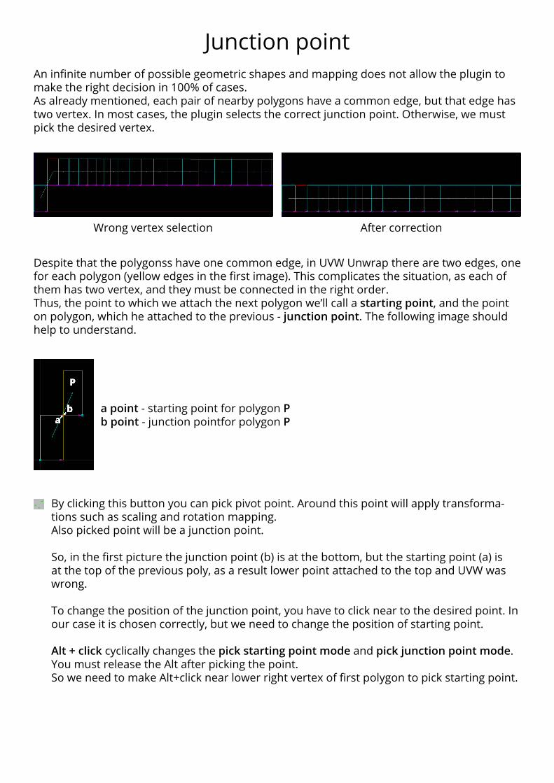
Junction pointAn infinite number of possible geometric shapes and mapping does not allow the plugin to make the right decision in 100% of cases.As already mentioned, each pair of nearby polygons have a common edge, but that edge has two vertex. In most cases, the plugin selects the correct junction point. Otherwise, we must pick the desired vertex.
Wrong vertex selection After correction
Despite that the polygonss have one common edge, in UVW Unwrap there are two edges, one for each polygon (yellow edges in the first image). This complicates the situation, as each of them has two vertex, and they must be connected in the right order.Thus, the point to which we attach the next polygon we’ll call a starting point, and the point on polygon, which he attached to the previous - junction point. The following image should help to understand.
By clicking this button you can pick pivot point. Around this point will apply transforma-tions such as scaling and rotation mapping.Also picked point will be a junction point.
So, in the first picture the junction point (b) is at the bottom, but the starting point (a) is at the top of the previous poly, as a result lower point attached to the top and UVW was wrong.
To change the position of the junction point, you have to click near to the desired point. In our case it is chosen correctly, but we need to change the position of starting point.
Alt + click cyclically changes the pick starting point mode and pick junction point mode. You must release the Alt after picking the point.So we need to make Alt+click near lower right vertex of first polygon to pick starting point.
a point - starting point for polygon Pb point - junction pointfor polygon P

1. PolygonMap working with selected polygons and edges.If there are selected polygons before in modifier stack, the mapping will be created just for them.If you select one of the edges, this edge will be alignment edge.
2. Pick Mapping tool (pipette) works with different vertex. By clicking on one area you get one result, and click on the other - the result will be different.
3. Pick Mapping tool works with a selected polygon. This means that if you have selected any polygon, then picked mapping size will be adjusted to the size of this polygon. To select the polygon you can use Select Link tool (green arrow in Links Rollout). To remove the selection you can click anywhere outside the polygons.
4. The fit mapping size buttons (F) next to the size values work only by the double click if Links are enabled. When Links are off, fitting works immediately.
5. All transformation tools used in the Parameters Rollout (move, rotate, scale, mirror and alignment edges) are applied to the whole links branch if the Next option is on. It is important to remember, when apply any transformation or alignment.
6. Any transformations resets by double click on the desired polygon. Reset transformations applies to whole link branch. Each transformation can be reset by the same tool. For exam-ple, the rotation can be reset by double click only when using the rotate tool, and move trans-formation will not be reset. To completely reset all transformations you can use Reset tool.
Additional info

Mapping creation procedureHere described the easiest and fastest way to build links and mapping.
For example, we’ll take this object and apply material with default PM texture.
Then apply PolygonMap modifier. Last or default settings will be used. If default, then automatiс links will be generated too.
Fit Arrow size in Viewport Rollout, so we can clearly see it.Most likely automatic links will be in wrong order, because they will not start from the first polygon. You must avoid this, because there will be a problems with alignment edges. That’s why we will disable autolinks and create them yourself.
Press
Click on the first polygon (building links is best done from left to right), then hold Shift and double-click on the second. That’s all, links are done!Next option must be enabled, which means that the transformations (and alignment) will be applied to whole link branch.
Then press
And select lower edge near first vertex. Click zone is marked by red dot.
It remains to adjust the size of our mapping, or simply press the F next to the Height. The height of the mapping will be the same as the height of the polygon.Optionally, you can click Quadrifity, but the texture may be slightly distorted in sharp bends. The same goes for Weld. These two options can lead to similar results, but their effect is dif-ferent, both are described in the Parameters Rollout chapter.

Cut all tiles on one walls object. For doors and windows you must set up cor-rect links between polygons. To pick starting point for tiles you can use align U axis tool.
Examples of mapping
Plane 50x50 segmentsMapping size as polygon sizeTransform Rollout: Angle 90 Rnd On Discr On
Can be used to random mapping of tiles.
Correct links and alignment edges on the example of brick walls.

Standart Box mapping.
PolygonMap mapping with random offset on both axes. Note the different mapping on each shelf.
The floor object contains many pol-ygons. Is mapped with only one big texture.Mapping size 3x4 meters, random off-set to both axes enabled.As a result, we get a non-repeating tex-tures of flooring on each board, using just one texture.