pole loading analysis guidelines for austin energy
TRANSCRIPT

Pole Loading Analysis Guidelines for
Austin Energy Infrastructure This document is intended to provide guidelines for third party vendors who perform pole loading analysis (PLA) on Austin Energy (AE) Infrastructure. Please direct all questions to [email protected].
All PLAs submitted to AE shall be prepared at the direction of a Texas licensed professional engineer(s), sealed by a Texas licensed professional engineer, and must conform to an AE approved process and methodology. If Licensee wishes to submit its proposed process and methodology to AE, AE agrees to review such process and methodology for prior acceptance. AE shall accept and rely on the documentation submitted by Licensee, but AE reserves the right to perform, or have a firm retained by AE perform, its own engineering and field evaluation. All costs for such engineering and field evaluations shall be paid by Licensee.
Austin Energy poles requiring a PLA:
• Poles that have 5 or more existing communication attachments • Junction poles- A pole that accommodates primary voltage service running in
more than two directions. These conductors can be a single primary tap off the main line or another primary circuit crossing the main line
• AE reserves the right to require a PLA on any pole

The pole attribute data described below shall be submitted with poles requiring a PLA. This data shall be used by Licensee to support the creation of a PLA in pole attachment identification software acceptable to Austin Energy. Licensee shall deliver a comprehensive Permitted Software PLA Report in PDF format which shall contain a summary of the detailed PLA results for each pole surveyed including safety factors for pole loading, guy wires, vertical loads, and all attachment heights. Prior to providing such a report, a sample report shall be provided to Austin Energy by Licensee along with Licensee’s request for Austin Energy’s acceptance of the report format. A single PLA Report in the approved format shall be generated for each pole by Licensee and submitted to Austin Energy. The PLA data shall include but not be limited to:
• Permitted Software: O-Calc Pro • Distribution poles shall follow these guidelines:
• Pole ID • A digital photo of each pole must be obtained. • Pole brand information (Length, Class & Species) • Span lengths and associated line angle for all attachments • Complete electrical and communication equipment data including type, size
and orientation. • Austin Energy’s current requirements for Loading District and Construction
Grades are as follows: o Electric distribution poles: NESC Grade C construction NESC Medium wind and ice requirement
o Electric distribution poles that are located at highway or railroad crossings: NESC Grade B construction NESC Medium wind and ice requirement
• Complete pole attachment attributes which include:

Type, Owner, height, clearance, and size of all electrical and communication attachments on the pole
Electrical wire tensions will be set per NESC Section 261.H.1.b at 35% of the rated breaking strength of the conductor (Maximum Design Tension)
• If Licensee would like to use a lower tension, a survey showing sag must be conducted and a determination of the maximum design tension using Southwire’s Sagten program must be made. Austin Energy may deny this method without cause.
• Total usage of the pole based on the available ground line moment capacity of the pole shall be less than 90%. Any pole exceeding 90% capacity shall be replaced with a calculated pole size which will pass the 90% usage capacity requirement
• Setting Depth o Wood Pole Depth shall be based on the tables shown in Attachment 2. o Steel pole depth is set according to tables in Attachment 1. o Soil conditions must be considered when determining setting depth,
especially East of IH-35 due to expansive clay issues. o Complete guying information including guy wire diameter, anchor
location and orientation. Austin Energy uses 7/16” EHS and 3/8” EHS guy wires. Please contact Austin Energy if a different size is found.
o • Height Measurements:
o Licensee shall submit collected digital images that are calibrated with a Permitted Software in order to extract attachment heights, or a survey showing the ground clearance at mid-span for all conductors, and pole height and attachment heights relative to the ground line. These attachment heights are applied in the pole model (described below) to their respective attachments. Overall pole height is also measured, and setting depth adjusted to exactly model field conditions.
• Steel poles are a special case, the contractor shall use the charts in Attachment 1 to determine the percentage of usage of the pole based on

the ground line moment. A usage value above 90% must be reviewed by Austin Energy to determine if a new class of pole is required.
• Distribution poles shall be run at either NESC Grade B for major road crossings or at NESC Grade C for all other poles.
• Code: NESC
NESC Rule 250B Grade B Ice thickness 0.25” Wind Speed (mph) 39.53 Wind Pressure (psf) 4 Transverse Wind LF 2.50 Wire Tension LF 1.65 Vertical LF 1.50
• Code: NESC
NESC Rule 250B Grade C Ice thickness 0.25” Wind Speed (mph) 39.53 Wind Pressure (psf) 4 Transverse Wind LF 1.75 Wire Tension LF 1.3 Vertical LF 1.90
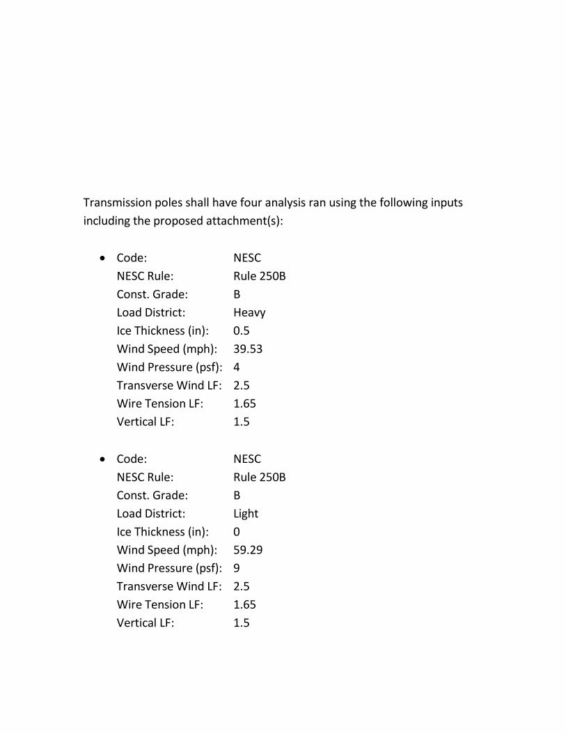
Transmission poles shall have four analysis ran using the following inputs including the proposed attachment(s):
• Code: NESC
NESC Rule: Rule 250B Const. Grade: B Load District: Heavy Ice Thickness (in): 0.5 Wind Speed (mph): 39.53 Wind Pressure (psf): 4 Transverse Wind LF: 2.5 Wire Tension LF: 1.65 Vertical LF: 1.5
• Code: NESC
NESC Rule: Rule 250B Const. Grade: B Load District: Light Ice Thickness (in): 0 Wind Speed (mph): 59.29 Wind Pressure (psf): 9 Transverse Wind LF: 2.5 Wire Tension LF: 1.65 Vertical LF: 1.5
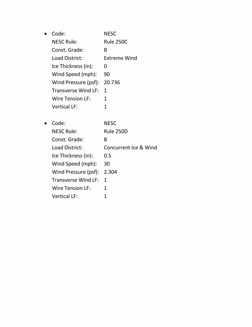
• Code: NESC NESC Rule: Rule 250C Const. Grade: B Load District: Extreme Wind Ice Thickness (in): 0 Wind Speed (mph): 90 Wind Pressure (psf): 20.736 Transverse Wind LF: 1 Wire Tension LF: 1 Vertical LF: 1
• Code: NESC
NESC Rule: Rule 250D Const. Grade: B Load District: Concurrent Ice & Wind Ice Thickness (in): 0.5 Wind Speed (mph): 30 Wind Pressure (psf): 2.304 Transverse Wind LF: 1 Wire Tension LF: 1 Vertical LF: 1

Attachment 1 – Steel Pole Information
Steel Pole Application Information
Epoxy Protective Coating Located
between (Ft)
Pole Length (Ft)
Setting Depth (Ft)
Pole Ground Line Moment Capacity (Ft-
Kips)
LD-2 or EQUIVALENT
4.00-9.00 40 7.00 120.00
4.50-9.50 45 7.50 135.00
5.00-10.00 50 8.00 145.00
5.75-10.75 55 8.75 155.00
6.25-11.25 60 9.25 170.00
7.00-12.00 65 10.00 180.00
7.50-12.50 70 10.50 195.00
8.00-13.00 75 11.00 218.00

8.50-13.50 80 11.50 233.00
9.50-14.50 85 12.50 248.00
10.00-15.00 90 13.00 264.00
10.50-15.50 95 13.50 280.00
11.00-16.00 100 14.00 296.00
11.50-16.50 105 14.50 313.00
12.00-17.00 110 15.00 331.00
13.50-18.50 120 16.50 367.00
LD-4 or EQUIVALENT
4.50-9.50 40 7.50 165.00
5.00-10.00 45 8.00 180.00
5.50-10.50 50 8.50 195.00
6.25-11.25 55 9.25 210.00
6.75-11.75 60 9.75 230.00
7.50-12.50 65 10.50 250.00
8.00-13.00 70 11.00 270.00
8.50-13.50 75 11.50 303.00
9.00-14.00 80 12.00 325.00
10.00-15.00 85 13.00 347.00
10.50-15.50 90 13.50 370.00
11.00-16.00 95 14.00 394.00
11.50-16.50 100 14.50 416.00
12.00-17.00 105 15.00 435.00
12.50-17.50 110 15.50 453.00

14.00-19.00 120 17.00 491.00
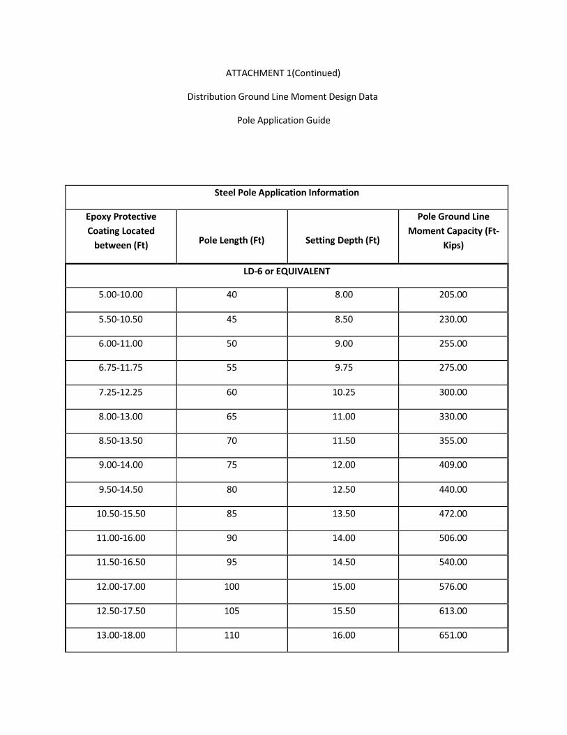
ATTACHMENT 1(Continued)
Distribution Ground Line Moment Design Data
Pole Application Guide
Steel Pole Application Information
Epoxy Protective Coating Located
between (Ft)
Pole Length (Ft)
Setting Depth (Ft)
Pole Ground Line Moment Capacity (Ft-
Kips)
LD-6 or EQUIVALENT
5.00-10.00 40 8.00 205.00
5.50-10.50 45 8.50 230.00
6.00-11.00 50 9.00 255.00
6.75-11.75 55 9.75 275.00
7.25-12.25 60 10.25 300.00
8.00-13.00 65 11.00 330.00
8.50-13.50 70 11.50 355.00
9.00-14.00 75 12.00 409.00
9.50-14.50 80 12.50 440.00
10.50-15.50 85 13.50 472.00
11.00-16.00 90 14.00 506.00
11.50-16.50 95 14.50 540.00
12.00-17.00 100 15.00 576.00
12.50-17.50 105 15.50 613.00
13.00-18.00 110 16.00 651.00
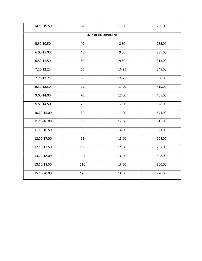
14.50-19.50 120 17.50 709.00
LD-8 or EQUIVALENT
5.50-10.50 40 8.50 255.00
6.00-11.00 45 9.00 285.00
6.50-11.50 50 9.50 315.00
7.25-12.25 55 10.25 345.00
7.75-12.75 60 10.75 380.00
8.50-13.50 65 11.50 415.00
9.00-14.00 70 12.00 455.00
9.50-14.50 75 12.50 528.00
10.00-15.00 80 13.00 571.00
11.00-16.00 85 14.00 615.00
11.50-16.50 90 14.50 661.00
12.00-17.00 95 15.00 708.00
12.50-17.50 100 15.50 757.00
13.00-18.00 105 16.00 808.00
13.50-18.50 110 16.50 860.00
15.00-20.00 120 18.00 970.00

ATTACHMENT 1 (Continued)
Distribution Ground Line Moment Design Data
Pole Application Guide
Steel Pole Application Information
Epoxy Protective Coating Located
between (Ft)
Pole Length (Ft)
Setting Depth (Ft)
Pole Ground Line Moment Capacity (Ft-
Kips)
LD-10 or EQUIVALENT
6.00-11.00 40 9.00 305.00
6.50-11.50 45 9.50 345.00
7.00-12.00 50 10.00 385.00
7.75-12.75 55 10.75 425.00
8.25-13.25 60 11.25 470.00
9.00-14.00 65 12.00 515.00
9.50-14.50 70 12.50 565.00
10.00-15.00 75 13.00 670.00
10.50-15.50 80 13.50 727.00
11.50-16.50 85 14.50 785.00
12.00-17.00 90 15.00 847.00
12.50-17.50 95 15.50 910.00
13.00-18.00 100 16.00 975.00
13.50-18.50 105 16.50 1025.00

14.00-19.00 110 17.00 1076.00
15.50-20.50 120 18.50 1176.00

Attachment 2
'
l
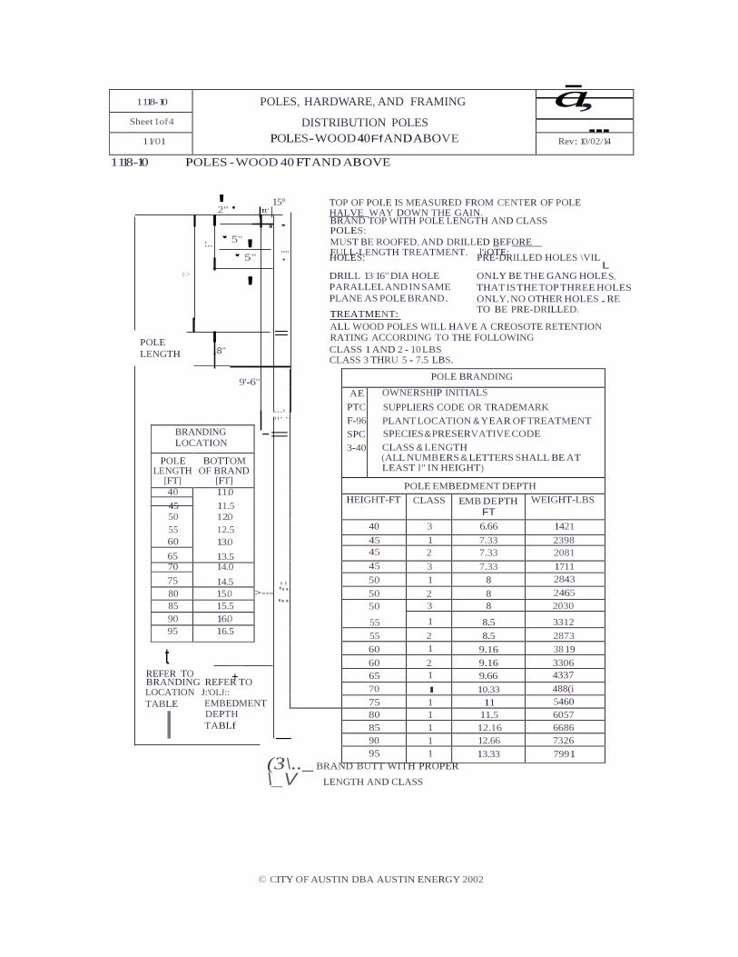
1118-10 POLES - WOOD 40 FT AND ABOVE
a-, ---
'2" ' tt'
15° TOP OF POLE IS MEASURED FROM CENTER OF POLE
HALVE WAY DOWN THE GAIN.
' :..
' 5"
.,
..... .
BRAND TOP WITH POLE LENGTH AND CLASS POLES: MUST BE ROOFED, AND DRILLED BEFORE FULL-LENGTH TREATMENT. l'iOTE: HOLES: PRE-DRILLED HOLES \VIL
POLE LENGTH
(-.>
L DRILL 13/16" DIA HOLE ONLY BE THE GANG HOLES. PARALLEL AND IN SAME THAT IS THE TOP THREE HOLES PLANE AS POLE BRAND . ONLY. NO OTHER HOLES . RE
TO BE PRE-DRILLED.
ALL WOOD POLES WILL HAVE A CREOSOTE RETENTION RATING ACCORDING TO THE FOLLOWING
8" CLASS 1 AND 2 - 10 LBS CLASS 3 THRU 5 - 7.5 LBS.
9'-6"
;;:'.: -=
45 11.5
,, >--- '"
'"
t REFER TO + BRANDING REFER TO LOCATION J:'OLJ:: TABLE EMBEDMENT
DEPTH TABLf
-
(3\.._ BRAND BUTT WITH PROPER \_V LENGTH AND CLASS
© CITY OF AUSTIN DBA AUSTIN ENERGY 2002
' 5"
' =
TREATMENT:
1118-10 POLES, HARDWARE, AND FRAMING
DISTRIBUTION POLES POLES - WOOD 40 Ff AND ABOVE
Sheet 1of 4 11/01 Rev: 10/02/14
POLE BRANDING
AE PTC F-96 SPC 3-40
OWNERSHIP INITIALS SUPPLIERS CODE OR TRADEMARK PLANT LOCATION & YEAR OF TREATMENT SPECIES & PRESERVATIVE CODE CLASS & LENGTH (ALL NUMB ERS & LETTERS SHALL BE AT LEAST l" IN HEIGHT)
POLE EMBEDMENT DEPTH HEIGHT-FT CLASS EMB DEPTH
FT WEIGHT-LBS
40 3 6.66 1421 45 1 7.33 2398 45 2 7.33 2081 45 3 7.33 1711 50 1 8 2843 50 2 8 2465 50 3 8 2030
55 1 8.5 3312 55 2 8.5 2873 60 1 9.16 38 19 60 2 9.16 3306 65 1 9.66 4337 70 I 10.33 488(i 75 1 11 5460
80 1 11.5 6057 85 1 12.16 6686 90 1 12.66 7326 95 1 13.33 7991
BRANDING LOCATION
POLE LENGTH
[FT]
BOTTOM OF BRAND
[FT] 40 11.0
50 12.0 55 12.5 60 13.0 65 13.5 70 14.0 75 14.5 80 15.0 85 15.5 90 16.0 95 16.5