pogo project alaska – tailings and water...
TRANSCRIPT

POGO PROJECT ALASKA – TAILINGS AND WATER MANAGEMENT FOR A COLD REGIONS MINE1
Michael P. Davies2 and Mathieu F. Veillette2
Abstract: The Pogo Project, a new gold mine in Alaska, was commissioned in January 2006 after approximately two years of construction. Construction followed an intensive permitting process. The project resides within the discontinuous permafrost belt of central Alaska. The region was unglaciated in the most recent glacial events in North America. Due to constraints including the location of the project directly adjacent to a productive salmon river, the regulatory scrutiny and the lack of fine-grained materials for conventional dam core design, the project’s design and construction required some innovative solutions for tailings, waste rock, and overall water management. The project includes a dry stack filtered tailings facility and a GCL/membrane-lined rockfill dam along with a series of surface water control and diversion structures developed in steep terrain with deep colluvium cover in many locations. The mine is a good example of how innovative geotechnical solutions can help meet mine waste and water management challenges in cold regions. Resume: Le projet pogo, une nouvelle mine d’or en alaska, fut demarre en janvier 2006 apres environ deux ans de construction et plusieurs annees de travail pour obtenir les permis requis. Le projet est situé au centre de l’alaska ou il se trouve un permafrost discontinu et l’endroit en question n’a pas été couvert de glacier durant la dernière période de glaciation en amérique du nord. Le projet à été soumis à un examen minutieux par plusieures agences gouvernementales parce que le projet est situé près d’une rivière à saumon productive. Le manque de matériaux de construction pour une digue conventionnel (avec un centre de matériel fins) à requis une conception innovatrice pour trouver des solutions pour les résidus de procédés, les roches stériles et la gestion des eaux. Le projet inclut un remblais a résidu filtré, un barrage de roche concassée avec une double membrane de gcl et lldpe, et une série de canaux de déviation afin de pouvoir contrôler l’eau de surface à travers un terrain très abrupte. Le projet est maintenant en opération et est un bon exemple de solutions innovatrices géotechnique pour la gestion des eaux et résidus de procédés pour les mines situées dans des régions climatiques froides.
Introduction
The Pogo project is a joint venture between Teck-Cominco Limited subsidiary Teck-Pogo inc. and subsidiaries of Sumitomo Metal Mining and Sumitomo Corp. The mine lies in the rolling hills of the Tanana uplands, 145 km southeast of Fairbanks as shown in Figure 1 below.
1 Paper was presented at Mining and the Environment IV Conference, Sudbury, Ontario, Canada, October 19-27, 2007 2 Dr. Michael P. Davies and Mr. Mathieu F. Veillette, AMEC Earth & Environmental Ltd, Vancouver, British Columbia, Canada
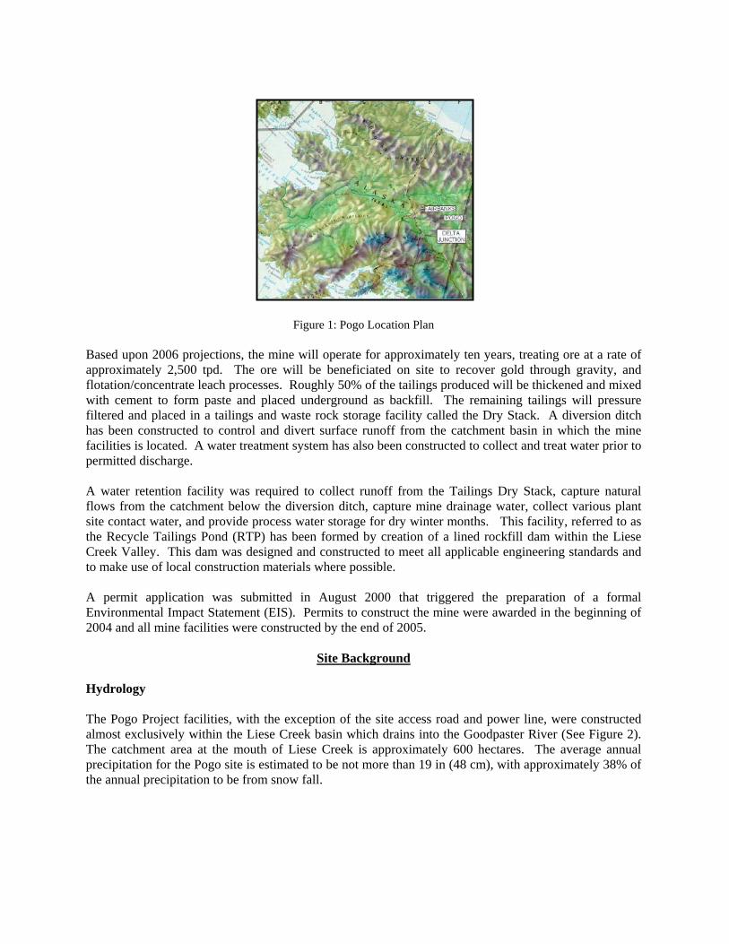
Figure 1: Pogo Location Plan Based upon 2006 projections, the mine will operate for approximately ten years, treating ore at a rate of approximately 2,500 tpd. The ore will be beneficiated on site to recover gold through gravity, and flotation/concentrate leach processes. Roughly 50% of the tailings produced will be thickened and mixed with cement to form paste and placed underground as backfill. The remaining tailings will pressure filtered and placed in a tailings and waste rock storage facility called the Dry Stack. A diversion ditch has been constructed to control and divert surface runoff from the catchment basin in which the mine facilities is located. A water treatment system has also been constructed to collect and treat water prior to permitted discharge. A water retention facility was required to collect runoff from the Tailings Dry Stack, capture natural flows from the catchment below the diversion ditch, capture mine drainage water, collect various plant site contact water, and provide process water storage for dry winter months. This facility, referred to as the Recycle Tailings Pond (RTP) has been formed by creation of a lined rockfill dam within the Liese Creek Valley. This dam was designed and constructed to meet all applicable engineering standards and to make use of local construction materials where possible. A permit application was submitted in August 2000 that triggered the preparation of a formal Environmental Impact Statement (EIS). Permits to construct the mine were awarded in the beginning of 2004 and all mine facilities were constructed by the end of 2005.
Site Background Hydrology The Pogo Project facilities, with the exception of the site access road and power line, were constructed almost exclusively within the Liese Creek basin which drains into the Goodpaster River (See Figure 2). The catchment area at the mouth of Liese Creek is approximately 600 hectares. The average annual precipitation for the Pogo site is estimated to be not more than 19 in (48 cm), with approximately 38% of the annual precipitation to be from snow fall.

Geology and Hydrogeology The upland or Pogo Ridge area is underlain by low-permeability bedrock consisting predominantly of igneous and metamorphosed sedimentary rocks. Permafrost has developed to a depth of up to 120 m below ground surface on the north-facing slope of this ridge, while on the south-facing slope it is virtually absent. The south-facing slopes are also more susceptible to freeze thaw effects and therefore tend to have a thicker overburden layer of finer grained material than the north-facing slopes. Bedrock is generally highly to moderately weathered on south-facing slopes which varied in depths from the ground surface from approximately 5 to 12 m. Bedrock on north-facing slope is generally 1.5 m deep from the ground surface and ranged from slightly weathered to fresh since the bedrock was preserved in permafrost. The water table beneath the ridge is deep and up to approximately 150 m below the ground surface. The Goodpaster River valley is underlain predominantly by highly permeable sands and gravels. These sediments are up to 30 m thick in the center of the valley, with their thickness decreasing towards the valley flanks. The water table is located at approximately 0.6 to 2.4 m below the ground surface in the Goodpaster floodplain. Seismicity Historic earthquake records indicate that the Aleutian Megathrust is home to two of the three largest earthquakes in recorded history. These earthquakes registered 9.1 and 9.2 on the Richter scale and occurred in 1957 and 1964, respectively. The historic records of Alaska also indicate there have been three earthquakes of magnitude 7.0 to 7.3 within 80 km of Fairbanks (USGS National Earthquake Information Centre Web Site). A M7.9 earthquake event took place 120 km from Fairbanks in November 2002. The peak ground acceleration (PGA) from the event was shown by the USGS to be about 0.1 g (10% chance of exceedance in 50 years) at the project site, and the return period was estimated to be at least 600 years. For project design work, PGA values of 0.2g related to the MCE were applied to critical structures.
Water Management Plan The Pogo project mining facilities have been designed to protect water quality in the Goodpaster River. The facilities have been designed to limit the project footprint and facilitate post-mining reclamation. Water management was a key driver for the entire Pogo project design. Two mine water treatment plants (MWTP) currently exist (one was constructed for the exploration period) at the Pogo project to treat all discharged effluent from the RTP dam or the underground workings. Treated water from the MWTP is piped to the off-river treatment works (ORTW) where the water is discharged into large mixing ponds before entering the Goodpaster River. The diversion ditch was designed to intercept all non-contact water from mining facilities up to a 1 in 200 year, 24-hour precipitation event; i.e. a 4.6 in (11.7 cm) rainfall. The typical cross section of the diversion ditch was a v-shaped channel cut into bedrock that was 3 ft (0.9 m) deep with 1H:1V side slopes. The diversion ditch was quite challenging to build along the north-facing slopes where the existing ground was quite steep with an average slope of 1.5H:1V with permafrost conditions. No aufeis allowance was provided in the ditch design as operation & maintenance from the mine are to remove all the accumulated ice from winter months before spring freshet occurs. Shotcrete was used to line sections of bedrock that had a higher permeability or sections where bedrock was not encountered (See Figure 3).

Dry Stack
Due to the lack of an assured geographic setting to provide a conventional tailings pond, an innovative solution was utilised to store surface tailings and waste rock. A tailings Dry Stack is an entity when dewatered (typically filtered) tailings are placed in an unsaturated state at/near their optimum compactive moisture (Davies and Rice, 2001). The Dry Stack is a facility where tailings that have been pressure filtered to a moisture content of about 15% are placed into one of two areas used for either winter or summer placement. In the summer period, assumed to be not more than four months, tailings are placed in lifts and compacted, and provide a structural shell for the dry stack. In addition to tailings storage, the dry stack provides encapsulation of mineralized waste rock to minimize the potential for oxidation processes to occur (Figure 3 shows the Dry Stack facility with relation to the RTP). The Dry Stack start-up facilities were constructed during the winter months from November 2004 to February 2005. Flow-Through Drains The flow-through drains, constructed in the existing stream valleys within the Dry Stack area, augment the existing drainage courses and allow them to pass runoff and/or diversion ditch bypass under the dry stack. Conservatively, for security following mine closure, the flow-through drains have been designed with significantly higher flow capacity than previously measured flows in Liese Creek, let alone the decreased flows present in light of the diversion ditch. The rockfill used in the flow-through drains was between 30 and 90 cm in size, and separated from the tailings by a series of granular filters. The rockfill was sloped at about 1.5H:1V, resulting in a flow-through drain with a base width of 24 ft (7.3 m), a crest width of 12 ft (3.7 m) and a height of 4 ft (1.2 m). Based on this drain size, the flow-through drains can pass approximately 120 times the pre-diverted average daily flow of 0.47 cfs (12.6 l/s) measured at a United States Geological Survey gauge on Liese Creek. Perimeter Ditches Perimeter ditches will be constructed around the tailings Dry Stack on an annual basis to route runoff around from the surface of the Dry Stack during operation. To provide sufficient storm water flow capacity, these ditches will be approximately 1 ft (0.3 m) deep with a base width of 3 ft (0.9 m). The perimeter ditches provide a redundant, surface water handling system to the flow-through drains. Starter Berm and Toe Berm The starter berm (provided from the RTP reservoir excavation) and toe berm (provided from quarried rockfill) were constructed to provide an initial start-up storage requirement of 2 years of production. The rockfill toe berm, downstream of the starter berm acts as a foundation for the shell area and allows the crest of the tailings shell to reach a sufficiently high elevation to contain the final general placement area. The remainder of the toe berm will be constructed during operations to stay ahead of shell tailings requirements.

General Placement Area The general placement area includes the upstream catchment of the starter berm and tailings shell. This area will be used for tailings storage year-round, but exclusively during winter months when snow and ice could potentially affect the placement and compaction of these materials. The general placement area will be constructed to promote lateral drainage of surface runoff into the flow-through drains. During operation of the mine, tailings and mineralized development rock will be co-disposed in the general placement area of the dry stack such that the rock is encapsulated by tailings. The purpose of encapsulating the rock is to prevent preferential seepage paths and to significantly reduce the potential oxidation of any remnant sulphide minerals in the rock. Shell Placement Area Above the toe berm, the shell of the Dry Stack will be raised annually using compacted tailings. Instead of one long flat slope, the shell will be divided into segments with a maximum height of 60 ft (18 m) and will be constructed such that they have a convex shape to divert the water to the perimeter ditches. At the base of each slope segment, benches sloping laterally downwards will be constructed to collect sediment runoff and divert it into the perimeter ditches as well. These benches will have minimum widths of 15 ft (4.6 m), and may be built in a zig-zag fashion to accommodate equipment during shell construction.
RTP Dam For the Pogo site, the construction of a conventional earthfill, concrete or earth-cored rockfill dam would have posed significant logistical problems. All would have constrained construction to the summer months and would require construction materials not locally available. No fine grained materials were found near the Pogo site suitable for an impervious earth core and in the case of a concrete dam, significant quantities of cement would have had to be transported from out of state. By comparison, rockfill can be placed year round under typical conditions encountered at the Pogo site and, there were significant sources of competent rockfill available, most notably non-mineralized development rock, locally quarried rock or select blocky colluvium. Furthermore, rockfill dams with an upstream impervious lining (such as concrete or geosynthetics) have historically proven to be stable, to incur little deformation in earthquakes, to withstand high seepage flows without suffering internal erosion and have been overtopped without catastrophic failure of the dam (e.g. Bureau of Reclamation (1987), Sherard and Cooke (1987), ICOLD (1993), Cooke (1993), Seed (1979)). Therefore a rockfill dam was the selected dam type for Pogo. The RTP Dam for the Pogo mine was required to provide a reservoir with 40 million gallons (Mgal) or 151,400 m3 of available storage capacity based upon water balance projections derived during the design and permitting phase of the project. Based upon as-constructed conditions, approximately 43.3 Mgal (163,900 m3) of storage capacity is available at the as-constructed, and designed, spillway invert elevation of 2084 ft (635.2 m AMSL). The slight increase in capacity was due to an increase in the reservoir through development of a rockfill quarry (MS-G) within the reservoir footprint. Figures 4 and 5 show the as-built plan and cross sections of the RTP dam. The RTP dam structure can be summarized by the following key characteristics:
• The RTP is a combined excavated and above-grade rockfill dual lined dam structure; • The RTP dam is classified as a Class II dam (moderate hazard);

• The dam has a geosynthetic seepage barrier system. This liner system consists of a textured 60 mil (1.5 mm) linear low-density polyethylene (LLDPE) geomembrane underlain by a geocomposite clay liner (GCL) that is tied at the upstream toe into a bedrock grout trench in conjunction with a grout curtain system to minimize weathered bedrock seepage under the dam foundation;
• Filters were constructed to prevent migration of bedding material into the rockfill dam shell and protect the liner system (bentonite in the GCL governed the finer end of filtration requirement);
• The RTP dam has a concrete spillway along the left abutment to route PMF events while still providing 3 ft (0.9 m) of freeboard;
• The reservoir has a drawdown capacity of 600 gpm (37.9 l/s) with 2 submersible turbine pumps and has a 50,000 gal (189 m3) head tank;
• Four seepage collection wells are constructed 150 ft (45.7 m) downstream of the dam toe to pump back seepage water;
• Three monitoring wells are located 400 ft (121.9 m) downstream of the downstream dam toe for water quality monitoring;
• The dam is 90 ft (27.4 m) high and has a 550 ft (167.6 m) long crest; • The lined crest is set at 2090 ft (637 m) elevation and the spillway weir at 2084 ft (635.2 m);
Table 1 – RTP As-Built Planned Storage Volume
Component Quantity (m3)x10
3Criteria
Dead Storage 3.5 Freeboard for Dry Stack Sediments
Mill Water Supply
41.6 Winter Makeup Needs
Flood Storage 52.2 1:10 year, 24 hr duration
Extra storage to prevent spillway use
66.6 Spillway use probability ~20 to 30 events in 1000 years (<<1/10 years)
Total Volume 163.9 Construction Sequencing The RTP dam was constructed in two campaigns. The footprint stripping, reservoir excavation (168,200 m3), base filter placement and rockfill shell placement (76,500 m3) occurred from November 2004 to February 2005. The second construction campaign occurred from May 2005 to November 2005 for the filter and cover layer processing and placement, liner system (11,100 m3), grout trench, grout curtain, spillway and piping works. RTP Dam Filters Although the dam has been provided with a dual liner system, internal erosion concerns were still addressed for design completeness. To mitigate against piping or migration of processed bedding fines into the rockfill dam, filter compatibility should exist between adjacent soil and rock materials. There are three distinct zones that required filter compatibility:

• Between the liner bedding layer and the rockfill; • Between the rockfill and the overburden foundation; • Between the cover material and the rip rap;
The base filter beneath the RTP dam rockfill shell was 2 ft (0.6 m) thick and the filters on the face of the RTP dam were 1 ft (0.3 m) thick to enable proper placement. The filters were nominally compacted by low ground pressure D4 and D5 sized dozers. The filter and cover materials were all placed from the bottom up as this method prevents segregation. Table 2 presents a summary of the RTP dam zones. In terms of requisite filters for the RTP Dam, the project’s available granular materials from the ORTW excavation (See Figure 2) proved an excellent and suitable source to meet the design requirements. The majority of the designed filter layers were processed in the field with relative ease. Grout Trench and Liner System The grout trench is one of the key features of this dam, as it represented the physical link between the differentially weathered bedrock and the liner system. This trench was also used to cap the various campaigns of grout-injected boreholes for the cut-off works and to allow mass pouring for concrete that created the liner system tie-in block. The liner system was installed as described below:
• The liner system was rolled down from top to bottom from the dam crest. GCL panels were only 150 ft (45.7 m) long and the RTP dam face has a max length of 260 ft (79.2 m). Panels were then placed “bottom-up” to have the horizontal seam as high as possible.
• GCL horizontal seams had 2 ft (0.6 m) of overlap with powdered bentonite between seams and vertical self-healing seams were overlapped 6 to 9 inches (15 to 23 cm) per manufacturer specifications.
• The LLDPE liner was placed in a similar fashion with the horizontal seams placed as high up on the face of the dam as possible.
• Both the GCL and LLDPE liners were laid on top of the initial grout cap (~0.3 m thick) leaving the back 1/3 of the grout cap not covered by the liners. Another 0.3 m of grout capping was then placed over the liners. This configuration allowed for a good bond between the backside of the bedrock grout trench and the liner system.
Grout Curtain Based upon the design criteria and modelled results, it was concluded that foundation improvement (e.g. grout curtain) was not entirely necessary to prevent appreciable seepage but it would be prudent in case undetermined structures existed at the dam axis. The goal of selected foundation treatment was to create a grout curtain to increase the length of any potential seepage paths and to generally lower the bulk hydraulic conductivity of the weathered bedrock and/or structures within the rock. From previous site investigations, the weathered bedrock permeability was estimated to be “10-6 m/s”. Seepage analysis was based on the grout curtain yielding an average permeability from 10-7 to 10-8 m/s. As shown in Figure 4, there are 3 different bedrock types within the RTP dam footprint. On the north abutment is highly weathered diorite, the toe area is slightly weathered paragneiss and the south abutment is comprised of fresh diorite. All faults within the reservoir are also near vertical. The grout curtain process included four sequential stages of grout holes which are defined below: • Primary Holes (41), spaced 20 ft (6.1 m) apart (60o to 0o)

• Secondary Holes (38), spaced 20 ft (6.1 m) apart in between P holes and crossed the P holes at 60o towards the hill side
• Tertiary Holes (25), spaced 10 to 15 ft (3 to 4.6 m) apart and 5 ft (1.5 m) from P and S holes were placed from the north abutment to the toe where higher grout takes had occurred
• Grout Trench (GT) Holes (53), drilled through the grout cap (15 to 46 cm thick) in bedrock trench to seal upper bedrock zone, spaced between 10 to 20 ft (3 to 6.1 m) depending on locations
Stage-up grouting was used as much as possible, but stage down grouting had to be used when boreholes kept caving in at the toe area (caused by high water table) and several attempts were made to drill the holes. Pressure grouting a typical 50 ft (15.2 m) deep hole was carried out in 3 stages upwards from 35 ft (10.7 m), 20 ft (6.1 m) and 5 ft (1.5 m). Typical grouting procedures, in terms of limit pressures and completion criteria, were as follows: • 1.0 psi/ft (23 kPa/m) was used in HW to MW bedrock (north abutment) • 1.5 psi/ft (34.3 kPa/m) was used in MW to SW bedrock (toe Area) • 2.0 psi/ft (46 kPa/m) was used in SW to F bedrock (south abutment) • Typically, grout refusal was found to be less than 1 gpm (3.8 l/min) grout take for 10 minutes • Grouting usually started with 3:1 grout mix ratio for a batch of 50 gal (189 liters). If a hole was a
grout taker, started with 3 batches at 3:1, then if flow was still >10 gpm (0.6 l/s), placed 2 batches of 2:1 and if hole still took 5 gpm (0.3 l/s), sealed it with 1:1 mix. All grout mixes included 1% of bentonite and 4 ounces (113 grams) of welan gum per cement weight for effective viscosity and better overall grout flow.
Approximately 1,400 bags of cement were used over 9,000 lineal ft (2.7 km) of grout holes for a total of 22,200 gal (84 m3) of grout slurry injected. Packer testing following the grout curtain campaign indicated an average permeability of 10-7 m/s, which met design criteria. A final indicator that the grout curtain was successful was that grouted GT holes in previous areas of high grout take took approximately 10 times less grout on average.
Summary and Conclusions The Pogo mine project posed some unique geotechnical and water management challenges within a sensitive environmental setting. Key issues were foundation assurance within discontinuous permafrost, seepage and water controls measures with respect to the water supply/collection dam, tailings dry stack and the diversion ditch. The mine is into its initial year of operation and the geotechnical and water management solutions appear to be compatible with successful mine operation.
Acknowledgements The writers would like to thank Teck-Cominco the permission to publish this project account. We also thank the various AMEC and Teck-Cominco engineers and construction personnel the authors worked with over the project’s tenure who assisted in taking good designs and making them even better constructed entities.
References AMEC Earth & Environmental a division of AMEC Americas Ltd. (2004) Pogo Gold Project RTP Dam
Design Report, Final Report, issued to Teck-Cominco. January 2004.
AMEC Earth & Environmental a division of AMEC Americas Ltd. (2006) Pogo Mine Dry Stack Tailings Facility, OMS manual and EPP, issued to Teck-Cominco. January 2006.
AMEC Earth & Environmental a division of AMEC Americas Ltd. (2006) Pogo Gold Project RTP Dam 2004-2005 As-Built Report, issued to Teck-Cominco. April 2006.
Bureau of Reclamation, (1987), Design of Small Dams, third edition, A Water Resources Technical Publication, US Department of the Interior, 1987.
Cooke, B.J., (1993), “Rockfill and the Rockfill Dam”, International Symposium on High Earth-Rockfill Dams, Beijing China, October 26-29, 1993.
Davies, M.P., and S. Rice (2001), “An alternative to conventional tailings management – “dry stack” filtered tailings”, Tailings and Mine Waste ‘01, January, 2001, pp. 411-420.
ICOLD (1993), Rock Materials for Rockfill Dams, Review and Recommendations, Bulletin 92. Seed, H.B. (1979) Considerations in the earthquake-resistant design of earth and rockfill dams.
Geotechnique 29, No. 3, pp. 215-263. Sherard, J.L. and J.B. Cooke, (1987), “Concrete Face Rockfill Dam: I. Assessment”, Journal of the
Geotechnical Engineering Division, American Society of Civil Engineers, Vol. 113, No. GT 10, pp 1096-1112.
Teck-Cominco (2002), Water Management Plan, February 2002.

Figure 2 – Pogo Project Overall Site Plan

Figure 3: Upper Liese Creek Site Plan of Diversion Ditch, Dry Stack and RTP Dam
Table 2: Summary of RTP Dam Material Zones
Zone Description Material Borrow Source and Processed Method Function FVII Base filter Pit run alluvium (well graded 20 cm
minus, 2% < #200) Pit run alluvium from the ORTW Primary pond
Prevent loss of fines from overburden foundation due to any potential Zone R1 seepage
R1 Rockfill Blasted rockfill (90 cm minus, 7.5 cm < 20%, #200 < 5%)
Blasted fresh diorite bedrock from MS-G and MS-E (rockfill sorted with an excavator)
Bulk mass of Dam. Structural support for filter zones and liner system
FI
Transition filter Pit run alluvium (well graded 20 cm minus, 2% < #200)
Pit run alluvium from the ORTW Primary pond
Prevent potential loss of fines from Zone FIV due to potential seepage forces, and provide structural support
FIV Filter layer Clean, well graded sand and gravel, (2.5 to 1 cm minus, max 5% < #40)
Screened pit run alluvium from the ORTW with 1 in (2.5 cm) size screen
Prevent potential loss of fines from Zone FVI due to potential seepage forces
FVI Bedding layer sand, (3 mm to #20 minus, max 20% < #100)
Pit run material from aeolian sand borrow at MS-15
Structural and bedding support for the liner system – required to be filter compatible
Liner LowPermeability Geocomposite Membrane
GCL overlain by a textured 60-mil (1.5 mm) LLDPE membrane, overlain by a 10-oz/yd (339 g/m2) non woven geotextile fabric
GCL provided from CETCO (Bentomat DN), textured 60-mil (1.5 mm) LLDPE provided by GSE
Minimize potential seepage losses through dam
FIII Cover layer Clean, well graded sand and gravel, (5 to 2.5 cm minus, max 20% < #100)
Screened pit run alluvium from the ORTW with 1.75 in (4.4 cm) size screen Protection layer for the Liner System
RR1 Rip rap layer blasted rockfill (30 to 20 cm minus, 2% < 1 cm)
Blasted fresh diorite bedrock from MS-E and then material processed into the 10" (25 cm) jaw of crusher for uniformity
Protection layer for FIII zone against potential wave/ice action in reservoir

Figure 4: As-Built RTP Dam Plan Layout

Figure 5: RTP Dam As-Built Cross Sections