pneumatics step-by-step - webs€¦ · pneumatics step-by-step (for the crio controller) 2011...
TRANSCRIPT

Pneumatics Step-by-Step(For the cRIO Controller)
2011 edition
FIRST Robotics Team 358, Hauppauge, NY
How to Assemble Your PneumaticsIt's a good idea to plan ahead and layout all your parts on a big table or the floor before you begin connectingthings, and of course a layout design is always helpful. For help with designing pneumatics circuits see:http://team358.org/files/pneumatic/PneumaticsForNewbies.pdf.This Step-by-Step goes through all the mechanical connections and pneumatic system testing, before adding inthe electronic side that powers it, and finally the computer controls, but we begin right away with running thecompressor with a battery to test for air leaks as each circuit stage is completed.
CompressorParts needed: compressor, emergency relief valve, (1) push-to-connect tube fitting, Teflontape
1. Attach the pressure safety valve to the compressor (must use Teflon tape as a seal)2. Add a tube fitting to the output port using Teflon tape3. Mount the compressor using the vibration dampers to avoid rattling everything else on
your robot loose.4. Test the compressor by connecting the wires directly to a 12v source briefly

High-Pressure CircuitParts needed: storage tank(s), pressure sensor, manual relief valve, gauge, push-to-connect tube fittings, brassfittings, tubing, Teflon tape.Most common mistake: not sealing everything with Teflon tape and not checking forleaks section by section as you go.
1. Add fittings to one or more storage tanks using Teflon tape2. Add pressure sensor using Teflon tape3. Add manual relief valve using Teflon tape4. Add pressure gauge using Teflon tape5. Leave tail to add 60psi regulator later, but plug it temporarily, e.g.,
or6. Connect all tubing7. Test again by connecting the compressor to a 12v source and watch the gauge climb. The sensor is not
yet hooked up, so it will not automatically stop yet.8. Check for leaks when you stop the compressor and correct any you find
Low-Pressure CircuitParts needed: all-black regulator, solenoid(s), cylinder(s), multiple push-to-connect tube fittings, brass fittings,tubing, Teflon tape.Most common mistakes: incorrect assembly of the regulator by not recognizing the low-pressure port. Not usingthe correct solenoid ports.
1. Assemble the all-black regulator using Teflon tapea. The low-pressure port indicated by an arrow gets a tube fitting using Teflon tapeb. The port opposite the low-pressure outlet is for the high-pressure input. Add a tube fitting for
high-pressure air using Teflon tapec. Add a pressure gauge to either of the remaining two ports using Teflon taped. Add the plug packed with the regulator to the final unused port using Teflon tape
2. Add the 60psi (all black) regulator to a tube from the tail-end of the High-Pressure Circuit.3. Assemble SMC solenoid if used or use the pre-assembled Festo or Bosch-Roxroth
a. Swap out any 24VDC ends for 12VDC replacements on the main body

b. Add the separate ports to the main body careful to use the rubber sealc. Add tube fittings to the input and output ports using Teflon tape
4. Connect regulator via tubing to one or more solenoids5. Add tube fittings to cylinders using Teflon tape6. Connect the solenoid(s) to cylinders with tubing7. If you will have an even lower-pressure circuit, then leave a tail plugged for testing8. Run the compressor as before to see if the circuit holds air. The solenoids cannot be tested yet. Adjust
the regulator to the low-pressure you want, e.g., 60-30psi.
For additional lower pressure circuits repeat as for the Low-Pressure Circuit above, but using the regulator withthe yellow ring.
Tubing Solenoid Valves
Festo (single solenoid)Fully assembled, simply push the tubing into the ports.
o Port 1 - pressure input – minimum of ~35psi for the valve to worko Port 2 – output to cylinder. relay1_fwd=0; means pressure is coming out (default position)o Port 3 - exhaust for excess air leaving cylindero Port 4 – output to other end of cylinder. relay1_fwd=1; means pressure is coming out
SMC (single & double solenoids)

This has to be assembled from several parts. 1) the main body, 2) the ports/gaskets, 3) screw SMCfittings. You'll need a miniature screwdriver, such as those used to fix eyeglasses. Then the tubing ispushed into the fittings.
o – minimum of ~20psi for the valve to worko "X" and "PE" are not used.o "EA" and "EB" are the exhaust for the "A" and "B" ports.o "A" & "B" go to the two ends of a cylinder
Bosch-Rexroth (single solenoid)Fully assembled, remove the grey nut and slide it onto the tubing, push the tubes onto the port, tightenthe grey nut to secure it.
o "P" – pressure inputo "B" - output to cylinder. relay1_fwd=0; means pressure is coming out (default position)
o "A" - output to other end of cylinder. relay1_fwd=1; means pressure is coming out
o "R" – exhaust port
cRIO WiringWe’ll assume the rest of your cRIO control system is already setup properly. Parts needed: black/red wire,female spade connectors, Power Distribution Panel, 20a snap-action breaker for each Spike used plus an extraone for the compressor's Spike, one Spike for each solenoid and one for the compressor.Most common mistakes: Not using color coded red/black wire making it easy to mis-wire, and not recognizingthe difference between: Digital Sidecar General Purpose Inputs/Outputs (GPIO) (used for Pressure Switch & other switches) Digital Sidecar Relay Outputs (used for spikes controlling solenoids and the compressor) Solenoid Bumper Outputs (used for controlling solenoids instead of Spikes/Relays) Digital Sidecar PWM outputs (not used in pneumatics) Analog Bumper Inputs (not used in pneumatics)
Compressor
Most common mistake: wiring the compressor backwards (no it will not suck air out, and it won’t breakanything).
1. Wire the compressor to a Spike using female spade connectors2. Replace the Spike fuse with a 20a snap-action breaker3. Wire the Spike to the Power Distribution Panel using more female spade connectors on the Spike4. Add the 20a snap-action breaker5. Connect the Spike to a Digital Sidecar Relay
Note: The compressor will run fine in reverse, just inefficiently, so make sure red goes to Spike M+.
Pressure Switch
1. Use only signal & ground – the outside pwm-cable wires, NOT power2. Connects to a Digital Sidecar GPIO Input.

cRIO Solenoid Module Breakout Board
Each breakout board on the solenoid module(s) must be wired back to the Power Distribution Panel using asmall white wago connector that plugs directly into the breakout board. The other end of this wire at thePower distribution Panel end has two wiring choices:
1. For 12v operation wire the other end to a pair of the mid-sized wago connectors on the PowerDistribution Panel with a 20a breaker.
2. For 24v operation wire the other end to the special cRIO connector on the Power Distribution Panel. ThecRIO connector is labeled V - C - NC - C, but it is actually wired V - C - V - C, meaning +24V -GROUND - +24V - GROUND. Use the spare connection points.
You can see a photo of the solenoid breakout board mounted atop a cRIO solenoid module in the picture onthe next page.
Solenoid Valves
1. The SMC solenoid valves do not come pre-assembled, so you have a little bit of work to do. Partsneeded: solenoid, base, gasket & screws, screw fittings. Screw the solenoid and base together with agasket between them. Be careful to get the gasket in straight or the valve will leak. Not all the base portsneed fittings, one is simply an exhaust port. Fittings go in the ports labeled “A”, “B”, and “P.”
“A” and “B” will be for the two ends of your piston or actuator “P” stands for “Pilot” and that’s the input pressure line. “R” is the exhaust port and doesn’t need a fitting at all.
2. Add wires to the solenoid(s) connectors if necessarya. Festo (pre-2010) - Slide the gray connector from the black housing (can be pushed out from top
with supplied screw), and wire 1 – Negative, 2 – Positive. Caution: some Festo valves useterminal 3 instead of 2, so if one way doesn’t work try switching them.
b. Festo (2010) – come wired. Caution: these are 24v!c. (old) Bosch-Roxroth - Two connectors are included, crimp and wire onto the connectors and
then just push one over each spade.d. SMC’s already have wires.
3. On the cRIO you have two wiring choices: Solenoid Bumper (simplest) or Spike/Relay (as was usedexclusively on the older IFI controllers. For detailed wiring consult the wiring diagrams:
Power (http://team358.org/files/programming/ControlSystem2009-/2010_Robot_Power_Distribution_RevA.pdf)
Control (http://team358.org/files/programming/ControlSystem2009-/2009%20Data%20diagram.pdf)
a. To wire the solenoid directly to the Solenoid Bumper:3. It’s the cRIO module with the 8 green status LEDs and the associated attachment that is shorter than the
look-alike Analog Bumper.

4. A single solenoid uses one Solenoid Bumper output, while a double solenoid must use two SolenoidBumper outputs. Red wire goes to “+” on the Bumper, and black wire goes to “-“ as marked on theBumper cover.
b. To wire the solenoid to a Spike use female spade connectors.i. Single-action solenoid (Festo, Bosch-Roxroth and some SMCs) just wire black to M- and
red to M+
ii. Double-action solenoid (some SMCs) has 4 wires. The two reds go to M+ and M-respectively, while the two blacks join and go to the breaker panel. See the diagram.
iii. Wire the Spike to the Power Distribution Panel just as for the Compressor earlier andconnect a PWM cable between the Spike and a Digital Sidecar Relay.
iv. Add a 20a snap-action breaker for each solenoid4. If your code is ready and you have a basic pneumatics system setup then flip the on switch and quickly,
as the compressor runs, manually test each solenoid. Indicator lights on the Spikes should all be on andsolenoid indicator lights will go on as they are operated. Your cylinders should be moving in and out asyou manually operate the solenoids.
a. Festo (pre-2010 version) - moving the blue switch (bottom left in image) in the direction of thearrow will shift the valve manually.
b. Festo (2010 version) – IMPORTANT: This requires 24v power!Pushing the blue buttons (on the right and left in image) will shift the valve manually.
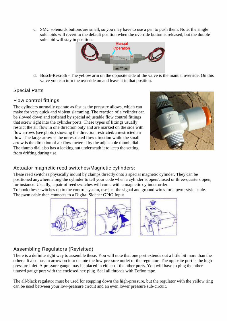
c. SMC solenoids buttons are small, so you may have to use a pen to push them. Note: the singlesolenoids will revert to the default position when the override button is released, but the doublesolenoid will stay in position.
d. Bosch-Rexroth - The yellow arm on the opposite side of the valve is the manual override. On thisvalve you can turn the override on and leave it in that position.
Special Parts
Flow control fittings
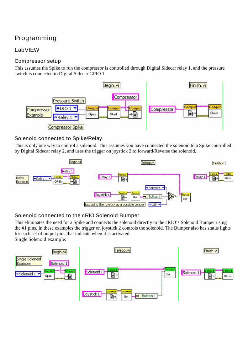
The cylinders normally operate as fast as the pressure allows, which canmake for very quick and violent slamming. The reaction of a cylinder canbe slowed down and softened by special adjustable flow control fittingsthat screw right into the cylinder ports. These types of fittings usuallyrestrict the air flow in one direction only and are marked on the side withflow arrows (see photo) showing the direction restricted/unrestricted airflow. The large arrow is the unrestricted flow direction while the smallarrow is the direction of air flow metered by the adjustable thumb dial.The thumb dial also has a locking nut underneath it to keep the settingfrom drifting during use.
Actuator magnetic reed switches/Magnetic cylinders:
These reed switches physically mount by clamps directly onto a special magnetic cylinder. They can bepositioned anywhere along the cylinder to tell your code when a cylinder is open/closed or three-quarters open,for instance. Usually, a pair of reed switches will come with a magnetic cylinder order.To hook these switches up to the control system, use just the signal and ground wires for a pwm-style cable.The pwm cable then connects to a Digital Sidecar GPIO Input.
Assembling Regulators (Revisited)
There is a definite right way to assemble these. You will note that one port extends out a little bit more than theothers. It also has an arrow on it to denote the low-pressure outlet of the regulator. The opposite port is the high-pressure inlet. A pressure gauge may be placed in either of the other ports. You will have to plug the otherunused gauge port with the enclosed hex plug. Seal all threads with Teflon tape.
The all-black regulator must be used for stepping down the high-pressure, but the regulator with the yellow ringcan be used between your low-pressure circuit and an even lower pressure sub-circuit.
Programming
LabVIEW
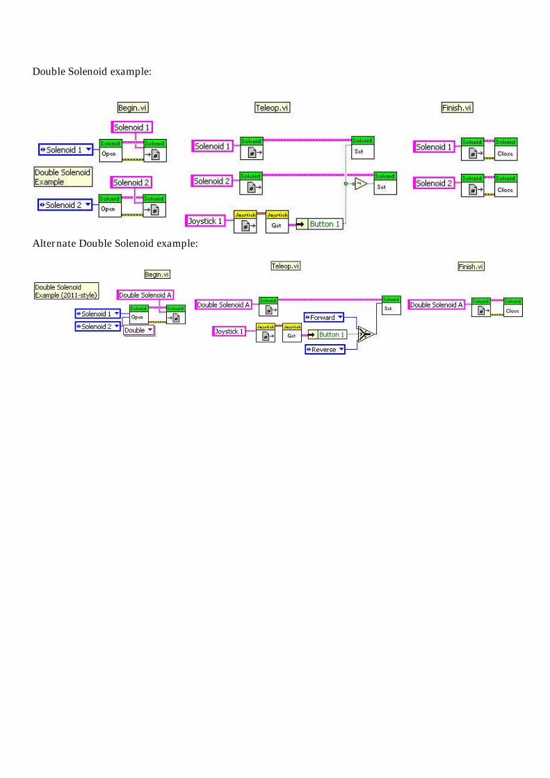
Compressor setup
This assumes the Spike to run the compressor is controlled through Digital Sidecar relay 1, and the pressureswitch is connected to Digital Sidecar GPIO 1.
Solenoid connected to Spike/Relay
This is only one way to control a solenoid. This assumes you have connected the solenoid to a Spike controlledby Digital Sidecar relay 2, and uses the trigger on joystick 2 to forward/Reverse the solenoid.
Solenoid connected to the cRIO Solenoid Bumper
This eliminates the need for a Spike and connects the solenoid directly to the cRIO’s Solenoid Bumper usingthe #1 pins. In these examples the trigger on joystick 2 controls the solenoid. The Bumper also has status lightsfor each set of output pins that indicate when it is activated.Single Solenoid example:
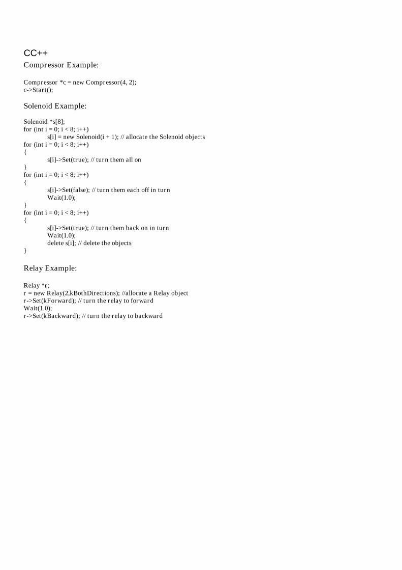
Double Solenoid example:
Alternate Double Solenoid example:
CC++Compressor Example:
Compressor *c = new Compressor(4, 2);c->Start();
Solenoid Example:
Solenoid *s[8];for (int i = 0; i < 8; i++)
s[i] = new Solenoid(i + 1); // allocate the Solenoid objectsfor (int i = 0; i < 8; i++){
s[i]->Set(true); // turn them all on}for (int i = 0; i < 8; i++){
s[i]->Set(false); // turn them each off in turnWait(1.0);
}for (int i = 0; i < 8; i++){
s[i]->Set(true); // turn them back on in turnWait(1.0);delete s[i]; // delete the objects
}
Relay Example:
Relay *r;r = new Relay(2,kBothDirections); //allocate a Relay objectr->Set(kForward); // turn the relay to forwardWait(1.0);r->Set(kBackward); // turn the relay to backward

Java
Compressor
Constructor Summary:
Compressor(int pressureSwitchSlot, int pressureSwitchChannel, int compresssorRelaySlot,int compressorRelayChannel)
Constructor Details:
public Compressor(int pressureSwitchSlot,int pressureSwitchChannel,int compresssorRelaySlot,int compressorRelayChannel)
Compressor constructor. Given a fully specified relay channel and pressure switch channel, initialize theCompressor object. You MUST start the compressor by calling the Start() method.Parameters:pressureSwitchSlot - The module that the pressure switch is attached to.pressureSwitchChannel - The GPIO channel that the pressure switch is attached to.compresssorRelaySlot - The module that the compressor relay is attached to.compressorRelayChannel - The relay channel that the compressor relay is attached to.
Solenoid
Constructor Summary:
Solenoid(int slot, int channel)
Constructor Details:
public Solenoid(int slot,int channel)
Constructor.Parameters:slot - The slot that the 9472 module is plugged into.channel - The channel on the module to control.
Method:
set(boolean on)
Set the value of a solenoid.
Method Details:
public void set(boolean on)
Set the value of a solenoid.Parameters:on - Turn the solenoid output off or on.
Relay
Constructor Summary:
Relay(int slot, int channel, int direction)
Relay constructor given the module and the channel.
Constructor Details:
public Relay(int slot,int channel,int direction)
Relay constructor given the module and the channel.Parameters:slot - The module slot number this relay is connected to.channel - The channel number within the module for this relay.direction - The direction that the Relay object will control.
Method:
set(int value)
Set the relay state.
Method details:
public void set(int value)
Set the relay state. Valid values depend on which directions of the relay are controlled by the object.When set to kBothDirections, the relay can only be one of the three reasonable values, 0v-0v, 0v-12v, or12v-0v. When set to kForwardOnly or kReverseOnly, you can specify the constant for the direction oryou can simply specify kOff and kOn. Using only kOff and kOn is recommended.Parameters:value - The state to set the relay.

TroubleshootingSort of a checklist to evaluate problems, the key is patient and methodical checkout of the entire system. General layout
o Parts in the wrong placeo Pistons too large and powerful or too small and under powered.o Pressure too high or too low (<30psi). solenoids require 20-30psi to operate.o Piston moves too fast. Use flow valves fittings to slow down overly speedy pistons.
Compressor won't shut offo Pressure sensor on the wrong side of the regulatoro Sensor or compressor controlling pwm-cables not hooked to the correct Digital Input or Relay
Output. If the sensor is not connected right, then typically Digital Inputs by default read like thecompressor should be running.
o Test the sensor output with a multi-meter (ohm setting) Compressor won't run
o Compressor not wired to the spike to the breaker panel correctlyo Missing spike breakero Pressure sensor mis-wired or not connected to the right Digital Inputo Fuse blown in the compressor spikeo Sensor or compressor controlling pwm-cables not hooked to the correct Digital Input or Relay
Output Pressure too high or too low (see testing for air leaks below)
o Kinked or pinched tubingo High-Pressure side
An uncommon reason can be the automatic release valve you added to the compressor. Itcomes pre-set for 125psi and shouldn't be tampered with, but it can be knocked out ofadjustment if the wrong piece was twisted by an inexperienced student. It does not let thehigh pressure get above 125psi no matter how much the compressor runs. It uses a double-nut to keep it secure, so with NO pressure in the system release the thin inner lock nut andtighten the larger, outer cap to increase the release pressure.
o Low-Pressure side Almost always due to the regulator,
Check that the low-pressure output port was used. The regulator may be set to a lower or higher pressure than you want. Adjust the
regulator by loosening the locking ring and twisting the base ring while watching theattached gauge change.
Pistons don't moveo Solenoid tubed incorrectlyo Solenoid/spike not wired correctlyo Spikes are controlled by RC Relay outputs. Make sure the spike pwm-style cable is hooked to a
Relay.o Software incorrecto Test solenoid manual override to see if it's a pressure or an electrical problem.
Festo - moving the blue switch in the direction of the arrow will shift the valve SMC solenoids buttons are small, so you may have to use a pen to push them. Note: the
single solenoids will revert to the default position when the override button is released, butthe double solenoid will stay in position.

Bosch-Rexroth - The yellow arm on the opposite side of the valve is the manual override. Onthis valve you can turn the override on and leave it in that position.
Pistons moving in the wrong directiono Reverse the tubing going into the cylinder ends
Regulatoro Confusing the one low-pressure output port with the three high-pressure ports. On each regulator
there is ONE port that is the low-pressure output, indicated by a directional arrow. The others are allhigh-pressure inputs/outputs.
o Not dialing in the desired low-pressure.o Not tightening the adjustment dial lock.
Air leakso Use a dead-end tube into a plugged brass fitting or a
loopback T-fitting to isolate sections that areleaking. Isolate leaking pressure sections one byone, disconnecting later sections so you canconcentrate on controlling leaks in one section at atime.
o Look for the big leaks first by feel. Don't be fooledby air flowing from the Victor or other fans in your robot. When you get it down to tiny leaks thenjudicious use of soap blowing bubbles, soapy water, Windex can help locate problem joints.
o Square cut tubing – tubing cut at any sort of angle rather than as square as possible will leak air fromthe system. The tube end needs to rest very flat inside the fittings to prevent air leaks.
o Rough/scratched tubing ends also will not seal correctlyo Failure to use Teflon tape to seal all screw thread fittingso Proper use of Teflon tape
Any Teflon that's been used once before should be replaced. Always use fresh Teflon andclean off all remnants. This means any on threads that have been screwed in once, then takeoff again need to have the Teflon replaced before screwing it on again.
Stop the Teflon several threads before the end to avoid scraps coming loose and clogging thesolenoid valves.
Wrap Teflon in the opposite the direction you'll be screwing the threads in (clockwise as youlook from the tip), so it pulls tighter rather than bunching up.
Make sure the wrap overlaps itself, but wrap it no more than twice around.o Cut or nicked tubingo Damaged fittings having either damaged threads through general abuse, cross threading, etc., or the
seal on the push tube connection can be damaged from rough tubes, debris, or yanking the tube outtoo many times instead of releasing it properly.
o Leaky regulator or other partso Leaky solenoids
Large leaks could be caused by debris in the valve such as odd bits of Teflon tape or dirt. Tryreplacing the solenoid.
Most solenoid valves seem to suffer from slight leaks that slowly let air out of any system.No real solution to this problem other than for the SMC you can disassemble and rearrangethe gaskets between parts. You can test if this is your problem by temporarily blocking orlooping-back the exhaust ports.

Rarely, a valve can be stuck in an in-between state and you'll feel excess air escaping fromone of the open exhaust ports. The valves only operate if they have some minimum airpressure to start with. To reset a stuck valve, force it up to minimum operating pressure byblocking the valve leaking exhaust vent with your finger, you can easily hold in the pressure,and the valve will self-reset at 20-30psi.
Air used too quicklyo Oversized actuators. Place your solenoid valves as close to the cylinders as possible to minimize that
little bit of volume needed to fill the tubing.o Add more storage tankso Too many actuatorso Actuators used too ofteno Low pressure, 60psi or less, is too high, so too much stored air gets used too quickly.o Solenoids will stop operating when the system pressure drops too low (20psi for SMC & Bosch-
Roxroth, 30psi for Festo). The running compressor provides .4 cubic foot of air per minute. Mis-wiring
o Sensor PWM-style cable uses only signal and ground, NOT power.o Solenoido Sometimes the SMC solenoids come with 24volt coils that must be replaced with 12v coils. Check to
see each coil is printed with "12vdc."

Parts is PartsParts photos to help you identify what's what are shown in the FIRST Pneumatics Manual. The pneumaticssystem is divided into a high pressure circuit where pressure is stored at 120psi, and one or more low-pressurecircuits at 60psi or less, known as working pressure.
High Pressure parts
Air compressorStorage tank(s) - 18.85 cu-in per tankPressure release – you must be able to manually dump the pressurized air in your systemPressure gauge – must read 120psi or less at all timesPressure sensor – must help the Robot Controller (RC) turn off the compressor at ~120psi (and on at ~95psi)Primary 60psi Regulator – takes tubing for high-side pressure, low-side exit, a pressure gauge, and a plug forthe extra port. Pay particular attention to the flow arrow so you use the special low-pressure outlet.
Low Pressure parts
Pressure gauge – must read 60psi or lessActuator(s) – pistons that push and pullActuator(s) with magnetic reed switches incorporatedSolenoid valve(s) –
Single action solenoid – has a home position it returns to when power is cut off. Double action solenoid – keeps an actuator in whatever position it was last in when power is cut off. Assembling SMC solenoid valves
Vacuum systemSecondary <60psi regulator(s) – optional to step pressure down to a second even lower operating pressure.Takes tubing for 60psi side, low-side exit, a pressure gauge, and a plug for the extra port. Pay particularattention to the flow arrow so you use the special low-pressure outlet.
General parts
All Brass fittings – plugs, 3-way,Brass/plastic hybrids – straight, right angleAll Plastic fittings – 3-way tube,Tubing